1
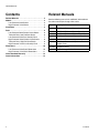
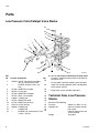
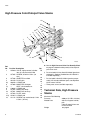
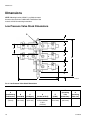
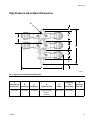
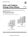
Instructions-Parts
Color and Catalyst
Change Valve Stacks
312783E
EN
For color/catalyst changing or distribution of industrial paints and coatings or fluids.
Important Safety Instructions
Read all warnings and instructions in this manual.
For complete warnings and instructions see your
proportioning system manual. Hazard symbols refer
to specific procedure risks. Save all instructions.
See pages 3 and 4 for model information, including maximum working pressure.
TI11665A
High Pressure Valve Stack 15V817
TI11668A
Low Pressure Valve Stack 15V813
Related Manuals
Contents
Related Manuals . . . . . . . . . . . . . . . . . . . . . . . . . . . 2
Models . . . . . . . . . . . . . . . . . . . . . . . . . . . . . . . . . . . 3
Low Pressure Valve Stacks . . . . . . . . . . . . . . . . 3
High Pressure Valve Stacks . . . . . . . . . . . . . . . . 4
Installation . . . . . . . . . . . . . . . . . . . . . . . . . . . . . . . . 5
Parts . . . . . . . . . . . . . . . . . . . . . . . . . . . . . . . . . . . . . 6
Low Pressure Color/Catalyst Valve Stacks . . . . . 6
Technical Data, Low Pressure Stacks . . . . . . . . 6
Low Pressure Valve Part Quantity Chart . . . . . . 7
High Pressure Color/Catalyst Valve Stacks . . . . 8
Technical Data, High Pressure Stacks . . . . . . . . 8
High Pressure Valve Part Quantity Chart . . . . . . 9
Dimensions . . . . . . . . . . . . . . . . . . . . . . . . . . . . . . 10
Low Pressure Valve Stack Dimensions . . . . . . 10
High Pressure Valve Stack Dimensions . . . . . . 11
Graco Standard Warranty . . . . . . . . . . . . . . . . . . . 12
Graco Information . . . . . . . . . . . . . . . . . . . . . . . . 12
2
Related Manuals
See the following manuals for additional information on
the color and catalyst change valve stacks.
Manual
Description
312775
ProMix 2KS Manual System Installation
312776
ProMix 2KS Manual System Operation
312777
ProMix 2KS Manual System Repair-Parts
312778
ProMix 2KS Automatic System Installation
312779
ProMix 2KS Automatic System Operation
312780
ProMix 2KS Automatic System
Repair-Parts
312782
Dispense Valve
312787
Color Change Module Kit
312783E
Models
Models
Low Pressure Valve Stacks
300 psi (2.1 MPa, 21 bar) Maximum Fluid Working Pressure
Valve Stack
Part No.
Series
Valve Stack Description
Valve Part No.
Valve
Quantity◆
256994
1 color
2
15V812
2 color/catalyst change
3
256290
3 color/catalyst change
4
15V813
4 color/catalyst change
5
256292
5 color/catalyst change
6
256293
6 color/catalyst change
7
15V814
7 color/catalyst change
8
256295
8 color/catalyst change
9
256296
9 color/catalyst change
10
256297
10 color/catalyst change
11
256298
11 color/catalyst change
12
15V815
12 color/catalyst change
13
256300
13 color/catalyst change
14
256301
14 color/catalyst change
15
256302
256303
A
15 color/catalyst change
16 color/catalyst change
15X304
16
17
256304
17 color/catalyst change
18
256305
18 color/catalyst change
19
256306
19 color/catalyst change
20
256307
20 color/catalyst change
21
256308
21 color/catalyst change
22
256309
22 color/catalyst change
23
256310
23 color/catalyst change
24
256311
24 color/catalyst change
25
256312
25 color/catalyst change
26
256313
26 color/catalyst change
27
256314
27 color/catalyst change
28
256315
28 color/catalyst change
29
256316
29 color/catalyst change
30
256372
30 color/catalyst change
31
◆ Each stack includes one additional valve for solvent.
312783E
3
Models
High Pressure Valve Stacks
3000 psi (21 MPa, 210 bar) Maximum Fluid Working Pressure
Valve Stack
Part No.
Series
Valve Stack Description
Valve Part No.
Valve
Quantity◆
256995
1 color
2
15V816
2 color/catalyst change
3
256339
3 color/catalyst change
4
15V817
4 color/catalyst change
5
256341
5 color/catalyst change
6
256342
6 color/catalyst change
7
256343
7 color/catalyst change
8
256344
8 color/catalyst change
9
256345
9 color/catalyst change
10
256346
10 color/catalyst change
11
256347
11 color/catalyst change
12
256348
12 color/catalyst change
13
256349
13 color/catalyst change
14
256350
14 color/catalyst change
15
256351
256352
A
15 color/catalyst change
16 color/catalyst change
15X303
16
17
256353
17 color/catalyst change
18
256354
18 color/catalyst change
19
256355
19 color/catalyst change
20
256356
20 color/catalyst change
21
256357
21 color/catalyst change
22
256358
22 color/catalyst change
23
256359
23 color/catalyst change
24
256360
24 color/catalyst change
25
256361
25 color/catalyst change
26
256362
26 color/catalyst change
27
256363
27 color/catalyst change
28
256364
28 color/catalyst change
29
256365
29 color/catalyst change
30
256371
30 color/catalyst change
31
◆ Each stack includes one additional valve for solvent.
4
312783E
Installation
Installation
A
1. Connect 5/32 in. (4 mm) OD air actuation tubes
from the valve solenoids to the air inlets (A) of each
valve. See FIG. 1.
S
NOTE: The high pressure color change valve uses a
spring-operated valve closure vent (20) which does not
require a second air actuation line. If you are installing a
bare valve, remove the elbow fitting from the top port
and install the breather vent. Replace the spring with the
one marked with black stain. Both the breather and the
marked spring are shipped loose.
20
B
C
High Pressure Valve Stack
2. Connect fluid supply lines to the 1/4 npt(f) inlet (B) of
each valve adapter. Supply solvent to one valve (S)
at the top of the stack.
NOTE: Excessive inlet fitting torque may cause the fitting to extend past its normal depth and contact the
valve needle, resulting in misalignment and leakage.
After installing the inlet fitting, verify that the needle travels freely by charging the valve with air or removing the
cap and manually actuating the needle.
NOTE: Paint Circulating System
The color change valves have two fluid ports for
each individual valve. If you are circulating
paint, plumb the valves in one port and out the
other. Another option is to use a tee fitting to circulate.
NOTE: Verify that all unused fluid ports on the color
change valve stack are plugged before operation. An
open port will leak fluid.
TI11665A
S
A
A
B
C
TI11668A
Low Pressure Valve Stack
FIG. 1. Valve Stack Connections
3. Connect the gun fluid supply line to the fluid outlet
port (C) of the color change manifold.
NOTE: A check valve is recommended at the inlet of all
valves to prevent backflow if a valve fails, and to prevent
color crossover if two dead head valves are open at the
same time.
NOTE: High pressure valves are factory-set at one turn
open from fully closed. This setting provides the
required spring force to prevent fluid back flow from the
outlet manifold to the valve at outlet manifold pressures
up to 3000 psi (21 MPa, 210 bar). If valves on the stack
are not being used, close the valve completely or plug
the valve inlet and circulation ports.
If a valve is adjusted more than 1-1/4 turn open, back
flow pressure will be reduced.
312783E
5
Parts
Parts
Low Pressure Color/Catalyst Valve Stacks
16
10
8
9
3
7
4
2
*15
11
8
1
12
2
Ref.
No.
1
2
3
4
6
7
8
9
10
11
12
15*
16
Part No. Description
15X304 VALVE, low pressure; includes
item 15; see manual 312782
--SCREW; 5/16-24 x 5/8 in. (16
mm)
15T436 ADAPTER, manifold
101970 PLUG, pipe
15T793 MANIFOLD, fluid port
15T574 SEAT, valve needle
110004 O-RING; ptfe
15T792 MANIFOLD, body
15T794 MANIFOLD, end cap
15X129 PLUG, housing
109450 O-RING; ptfe
--O-RING; ptfe
--SCREW, cap, socket-head; 1/4-20
x 5/8 in. (16 mm)
Qty
◆
◆
◆
1
◆
◆
◆
1
◆
◆
◆
◆
Part included in Seal Kit 15W621 (purchase separately). Kit includes additional parts; see Dispense
Valve manual 312782.
--- These parts are not available separately.
Technical Data, Low Pressure
Stacks
Maximum Fluid Working
Pressure
Wetted Parts
Weight
6
TI11669A
◆ See the Low Pressure Valve Part Quantity Chart
on page 7 to determine the quantity of each part in
your valve stack.
*
◆
6
300 psi (2.1 MPa, 21 bar)
303 sst, tungsten carbide,
ptfe, acetal
Color Change Valves: see
manual 312782
see page 7
312783E
Parts
Low Pressure Valve Part Quantity Chart
Find your Valve Stack Part No. in the left column and the desired reference number in the top row to find the part
quantity used in your valve stack.
Valve
Stack
Part No.
Reference Numbers
1
2
3
4
7
8
9
11
12
15
16
Weight
lb (kg)
256994
2
4
2
2
2
2
1
0
0
2
4
2.35 (1.07)
15V812
3
8
3
3
3
3
2
1
1
3
6
4.05 (1.84)
256290
4
8
4
4
4
3
2
0
0
4
6
4.70 (2.13)
15V813
5
12
5
5
5
4
3
1
1
5
8
6.40 (2.90)
256292
6
12
6
6
6
4
3
0
0
6
8
7.05 (3.20)
256293
7
16
7
7
7
5
4
1
1
7
10
8.75 (3.97)
15V814
8
16
8
8
8
5
4
0
0
8
10
9.40 (4.26)
256295
9
20
9
9
9
6
5
1
1
9
12
11.10 (5.03)
256296
10
20
10
10
10
6
5
0
0
10
12
11.75 (5.33)
256297
11
24
11
11
11
7
6
1
1
11
14
13.45 (6.10)
256298
12
24
12
12
12
7
6
0
0
12
14
14.10 (6.40)
15V815
13
28
13
13
13
8
7
1
1
13
16
15.80 (7.17)
256300
14
28
14
14
14
8
7
0
0
14
16
16.45 (7.46)
256301
15
32
15
15
15
9
8
1
1
15
18
18.15 (8.23)
256302
16
32
16
16
16
9
8
0
0
16
18
18.80 (8.53)
256303
17
36
17
17
17
10
9
1
1
17
20
20.50 (9.30)
256304
18
36
18
18
18
10
9
0
0
18
20
21.15 (9.59)
256305
19
40
19
19
19
11
10
1
1
19
22
22.85 (10.36)
256306
20
40
20
20
20
11
10
0
0
20
22
23.50 (10.66)
256307
21
44
21
21
21
12
11
1
1
21
24
25.20 (11.43)
256308
22
44
22
22
22
12
11
0
0
22
24
25.85 (11.73)
256309
23
48
23
23
23
13
12
1
1
23
26
27.55 (12.50)
256310
24
48
24
24
24
13
12
0
0
24
26
28.20 (12.80)
256311
25
52
25
25
25
14
13
1
1
25
28
29.90 (13.56)
256312
26
52
26
26
26
14
13
0
0
26
28
30.55 (13.86)
256313
27
56
27
27
27
15
14
1
1
27
30
32.25 (14.63)
256314
28
56
28
28
28
15
14
0
0
28
30
32.90 (14.92)
256315
29
60
29
29
29
16
15
1
1
29
32
34.60 (15.70)
256316
30
60
30
30
30
16
15
0
0
30
32
35.25 (15.99)
256372
31
64
31
31
31
17
16
1
1
31
34
36.95 (16.76)
312783E
7
Parts
High Pressure Color/Catalyst Valve Stacks
16
10
8
9
‡7
‡5
3
‡5
4
2
1
*‡15
8
11
8
6
ti11666c
2
Ref.
No.
1
Part No. Description
15X303 VALVE, high pressure; includes
item 15; see manual 312782
2
15T875 SCREW; 5/16-24 x 5/8 in. (16
mm)
3
15T436 ADAPTER, manifold
4
101970 PLUG, pipe
5‡
109450 O-RING; ptfe
6
15T869 MANIFOLD, fluid port
7‡
--SEAT, valve needle; sst
8
110004 O-RING; ptfe
9
15T872 MANIFOLD, body
10
15T871 MANIFOLD, end cap
11
15T873 PLATE, blank
15*‡ 15Y627 O-RING; ptfe
16
121112 SCREW, cap, socket-head; 1/4-20
x 5/8 in. (16 mm)
Qty
◆
◆
◆
◆
◆
1
◆
◆
◆
1
◆
◆
◆
◆ See the High Pressure Valve Part Quantity Chart
on page 9 to determine the quantity of each part in
your valve stack.
‡ Parts included in Valve Seat Kit 24A861 (purchase
separately). (Optional Carbide Seat Kit 15U932 is
available separately.)
*
Part included in Seal Kit 15U933 (purchase separately). Kit includes additional parts; see Dispense
Valve manual 312782.
--- These parts are not available separately.
Technical Data, High Pressure
Stacks
Maximum Fluid Working
Pressure
Wetted Parts
Weight
8
3000 psi (21 MPa, 210 bar)
303 sst, tungsten carbide,
ptfe
Color Change Valves: see
manual 312782
see page 9
312783E
Parts
High Pressure Valve Part Quantity Chart
Find your Valve Stack Part No. in the left column and the desired reference number in the top row to find the part
quantity used in your valve stack.
Valve
Stack
Part No.
Reference Numbers
1
2
3
4
5
7
8
9
11
15
16
20
Weight
lb (kg)
256995
2
4
2
2
4
2
2
1
0
2
4
2
2.60 (1.18)
15V816
3
8
3
3
6
3
4
2
1
3
6
3
5.05 (2.29)
256339
4
8
4
4
8
4
3
2
0
4
6
4
5.20 (2.36)
15V817
5
12
5
5
10
5
5
3
1
5
8
5
7.65 (3.47)
256341
6
12
6
6
12
6
4
3
0
6
8
6
7.80 (3.54)
256342
7
16
7
7
14
7
6
4
1
7
10
7
10.25 (4.65)
256343
8
16
8
8
16
8
5
4
0
8
10
8
10.40 (4.72)
256344
9
20
9
9
18
9
7
5
1
9
12
9
12.85 (5.83)
256345
10
20
10
10
20
10
6
5
0
10
12
10
13.00 (5.90)
256346
11
24
11
11
22
11
8
6
1
11
14
11
15.45 (7.01)
256347
12
24
12
12
24
12
7
6
0
12
14
12
15.60 (7.08)
256348
13
28
13
13
26
13
9
7
1
13
16
13
18.05 (8.19)
256349
14
28
14
14
28
14
8
7
0
14
16
14
18.20 (8.26)
256350
15
32
15
15
30
15
10
8
1
15
18
15
20.65 (9.37)
256351
16
32
16
16
32
16
9
8
0
16
18
16
20.80 (9.43)
256352
17
36
17
17
34
17
11
9
1
17
20
17
23.25 (10.55)
256353
18
36
18
18
36
18
10
9
0
18
20
18
23.40 (10.61)
256354
19
40
19
19
38
19
12
10
1
19
22
19
25.85 (11.73)
256355
20
40
20
20
40
20
11
10
0
20
22
20
26.00 (11.79)
256356
21
44
21
21
42
21
13
11
1
21
24
21
28.45 (12.90)
256357
22
44
22
22
44
22
12
11
0
22
24
22
28.60 (12.97)
256358
23
48
23
23
46
23
14
12
1
23
26
23
31.05 (14.08)
256359
24
48
24
24
48
24
13
12
0
24
26
24
31.20 (14.15)
256360
25
52
25
25
50
25
15
13
1
25
28
25
33.65 (15.26)
256361
26
52
26
26
52
26
14
13
0
26
28
26
33.80 (15.33)
256362
27
56
27
27
54
27
16
14
1
27
30
27
36.25 (16.44)
256363
28
56
28
28
56
28
15
14
0
28
30
28
36.40 (16.51)
256364
29
60
29
29
58
29
17
15
1
29
32
29
38.85 (17.62)
256365
30
60
30
30
60
30
16
15
0
30
32
30
39.00 (17.69)
256371
31
64
31
31
62
31
18
16
1
31
34
31
41.45 (18.80)
312783E
9
Dimensions
Dimensions
NOTE: Mounting bracket 15U927 is available to mount
the color valve stack to a ProMix 2KS Fluid Station. See
manual 312787 for mounting instructions.
Low Pressure Valve Stack Dimensions
G
A
B
F
B
D
B
C
E
TI13553a
FIG. 2. Low Pressure Valve Stack Dimensions
A
(manifold cap
and screws)
B
(manifold)
C
(fluid port)
D
(A+total of B+C)
E
(width)
F
(mounting
hole
dimension)
0.5 in.
(13 mm)
2.061 in.
(52.3 mm)
1.07 in.
(27.2 mm)
Example shown with
three manifolds:
7.75 in.
(197 mm)
8.43 in.
(214.1 mm)
2.061 in.
(52.3 mm)
10
G
(mounting
hole size)
1/4-20
312783E
Dimensions
High Pressure Valve Stack Dimensions
G
A
B
F
B
D
B
C
E
TI13554a
FIG. 3. High Pressure Valve Stack Dimensions
A
(manifold cap
and screws)
B
(manifold)
C
(fluid port)
D
(A+total of B+C)
E
(width)
F
(mounting
hole
dimension)
0.62 in.
(15.7 mm)
2.25 in.
(57.2 mm)
1.07 in.
(27.2 mm)
Example shown with
three manifolds:
8.44 in.
(214 mm)
10.16 in.
(258.1 mm)
2.25 in.
(57.2 mm)
312783E
G
(mounting
hole size)
1/4-20
11
Graco Standard Warranty
Graco warrants all equipment referenced in this document which is manufactured by Graco and bearing its name to be free from defects in
material and workmanship on the date of sale to the original purchaser for use. With the exception of any special, extended, or limited warranty
published by Graco, Graco will, for a period of twelve months from the date of sale, repair or replace any part of the equipment determined by
Graco to be defective. This warranty applies only when the equipment is installed, operated and maintained in accordance with Graco’s written
recommendations.
This warranty does not cover, and Graco shall not be liable for general wear and tear, or any malfunction, damage or wear caused by faulty
installation, misapplication, abrasion, corrosion, inadequate or improper maintenance, negligence, accident, tampering, or substitution of
non-Graco component parts. Nor shall Graco be liable for malfunction, damage or wear caused by the incompatibility of Graco equipment with
structures, accessories, equipment or materials not supplied by Graco, or the improper design, manufacture, installation, operation or
maintenance of structures, accessories, equipment or materials not supplied by Graco.
This warranty is conditioned upon the prepaid return of the equipment claimed to be defective to an authorized Graco distributor for verification of
the claimed defect. If the claimed defect is verified, Graco will repair or replace free of charge any defective parts. The equipment will be returned
to the original purchaser transportation prepaid. If inspection of the equipment does not disclose any defect in material or workmanship, repairs
will be made at a reasonable charge, which charges may include the costs of parts, labor, and transportation.
THIS WARRANTY IS EXCLUSIVE, AND IS IN LIEU OF ANY OTHER WARRANTIES, EXPRESS OR IMPLIED, INCLUDING BUT NOT
LIMITED TO WARRANTY OF MERCHANTABILITY OR WARRANTY OF FITNESS FOR A PARTICULAR PURPOSE.
Graco’s sole obligation and buyer’s sole remedy for any breach of warranty shall be as set forth above. The buyer agrees that no other remedy
(including, but not limited to, incidental or consequential damages for lost profits, lost sales, injury to person or property, or any other incidental or
consequential loss) shall be available. Any action for breach of warranty must be brought within two (2) years of the date of sale.
GRACO MAKES NO WARRANTY, AND DISCLAIMS ALL IMPLIED WARRANTIES OF MERCHANTABILITY AND FITNESS FOR A
PARTICULAR PURPOSE, IN CONNECTION WITH ACCESSORIES, EQUIPMENT, MATERIALS OR COMPONENTS SOLD BUT NOT
MANUFACTURED BY GRACO. These items sold, but not manufactured by Graco (such as electric motors, switches, hose, etc.), are subject to
the warranty, if any, of their manufacturer. Graco will provide purchaser with reasonable assistance in making any claim for breach of these
warranties.
In no event will Graco be liable for indirect, incidental, special or consequential damages resulting from Graco supplying equipment hereunder, or
the furnishing, performance, or use of any products or other goods sold hereto, whether due to a breach of contract, breach of warranty, the
negligence of Graco, or otherwise.
FOR GRACO CANADA CUSTOMERS
The Parties acknowledge that they have required that the present document, as well as all documents, notices and legal proceedings entered into,
given or instituted pursuant hereto or relating directly or indirectly hereto, be drawn up in English. Les parties reconnaissent avoir convenu que la
rédaction du présente document sera en Anglais, ainsi que tous documents, avis et procédures judiciaires exécutés, donnés ou intentés, à la suite
de ou en rapport, directement ou indirectement, avec les procédures concernées.
Graco Information
For the latest information about Graco products, visit www.graco.com.
For patent information, see www.graco.com/patents.
TO PLACE AN ORDER, contact your Graco distributor or call to identify the nearest distributor.
Phone: 612-623-6921 or Toll Free: 1-800-328-0211 Fax: 612-378-3505
All written and visual data contained in this document reflects the latest product information available at the time of publication.
Graco reserves the right to make changes at any time without notice.
Original instructions. This manual contains English. MM 312783
Graco Headquarters: Minneapolis
International Offices: Belgium, China, Japan, Korea
GRACO INC. AND SUBSIDIARIES • P.O. BOX 1441 • MINNEAPOLIS, MN 55440-1441 • USA
Copyright 2008, Graco Inc. All Graco manufacturing locations are registered to ISO 9001.
www.graco.com
Revision E, August 2014