1
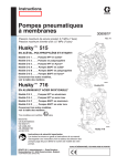
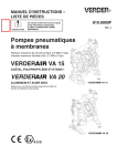
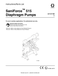
Instructions–Parts List
ALUMINUM
Huskyt 716 Air–operated
Diaphragm Pumps
308797P
Used to evacuate and transfer fluids.
100 psi (0.7 MPa, 7 bar) Maximum Fluid Working Pressure
100 psi (0.7 MPa, 7 bar) Maximum Air Input Pressure
Part No. 241407, Series D
with two–direction manifolds
Part No. 241408, Series D
with single–direction manifolds
Patents Pending
Important Safety Instructions
Read all warnings and instructions in this manual.
Save these instructions.
9246A
Model No. 241407
Table of Contents
Warnings . . . . . . . . . . . . . . . . . . . . . . . . . . . . . . . . . . . . . . 2
Installation . . . . . . . . . . . . . . . . . . . . . . . . . . . . . . . . . . . . . 4
Operation . . . . . . . . . . . . . . . . . . . . . . . . . . . . . . . . . . . . 10
Maintenance . . . . . . . . . . . . . . . . . . . . . . . . . . . . . . . . . . 11
Troubleshooting . . . . . . . . . . . . . . . . . . . . . . . . . . . . . . . 12
Service . . . . . . . . . . . . . . . . . . . . . . . . . . . . . . . . . . . . . . 13
Parts Drawing . . . . . . . . . . . . . . . . . . . . . . . . . . . . . . . . . 18
Parts List . . . . . . . . . . . . . . . . . . . . . . . . . . . . . . . . . . . . . 19
Torque Sequence . . . . . . . . . . . . . . . . . . . . . . . . . . . . . 20
Technical Data . . . . . . . . . . . . . . . . . . . . . . . . . . . . . . . . 21
241407 and 241408 Repair Kits . . . . . . . . . . . . . . . . . 21
Dimensions . . . . . . . . . . . . . . . . . . . . . . . . . . . . . . . . . . . 22
Performance Charts . . . . . . . . . . . . . . . . . . . . . . . . . . . 23
Graco Standard Warranty . . . . . . . . . . . . . . . . . . . . . . 26
Graco Information . . . . . . . . . . . . . . . . . . . . . . . . . . . . . 26
Symbols
Warning Symbol
WARNING
This symbol alerts you to the possibility of serious
injury or death if you do not follow the instructions.
Caution Symbol
CAUTION
This symbol alerts you to the possibility of damage to
or destruction of equipment if you do not follow the
instructions.
WARNING
EQUIPMENT MISUSE HAZARD
Equipment misuse can cause the equipment to rupture or malfunction and result in serious injury.
INSTRUCTIONS
This equipment is for professional use only.
Read all instruction manuals, tags, and labels before operating the equipment.
Use the equipment only for its intended purpose. If you are not sure, call your Graco distributor.
Do not alter or modify this equipment. Use only genuine Graco parts and accessories.
Check equipment daily. Repair or replace worn or damaged parts immediately.
Do not exceed the maximum working pressure of the lowest rated component in your system. This
equipment has a 100 psi (0.7 MPa, 7 bar) maximum working pressure at 100 psi (0.7 MPa,
7 bar) maximum incoming air pressure.
Use fluids and solvents that are compatible with the equipment wetted parts. Refer to the Technical Data section of all equipment manuals. Read the fluid and solvent manufacturer’s warnings.
Route hoses away from traffic areas, sharp edges, moving parts, and hot surfaces. Do not expose
Graco hoses to temperatures above 82C (180F) or below –40C (–40F).
Wear hearing protection when operating this equipment.
Do not lift pressurized equipment.
Comply with all applicable local, state, and national fire, electrical, and safety regulations.
Do not use 1.1.1–trichloroethane, methylene chloride, other halogenated hydrocarbon solvents or
fluids containing such solvents in pressurized aluminum equipment. Such use could result in a
chemical reaction, with the possibility of explosion.
2
308797
WARNING
TOXIC FLUID HAZARD
Hazardous fluid or toxic fumes can cause serious injury or death if splashed in the eyes or on the skin,
inhaled, or swallowed.
Know the specific hazards of the fluid you are using.
Do not lift a pump under pressure. If dropped, the fluid section may rupture. Always follow the
Pressure Relief Procedure on page 10 before lifting the pump.
Store hazardous fluid in an approved container. Dispose of hazardous fluid according to all local,
state and national guidelines.
Always wear protective eyewear, gloves, clothing and respirator as recommended by the fluid and
solvent manufacturer.
Pipe and dispose of the exhaust air safely, away from people, animals, and food handling areas. If
the diaphragm fails, the fluid is exhausted along with the air. Read Air Exhaust Ventilation on
page 6.
Never use an acetal pump to pump acids. Take precautions to avoid acid or acid fumes from
contacting the pump housing exterior. Stainless steel parts will be damaged by exposure to acid
spills and fumes.
FIRE AND EXPLOSION HAZARD
Improper grounding, poor ventilation, open flames or sparks can cause a hazardous condition and
result in a fire or explosion and serious injury.
Ground the equipment. Refer to Grounding on page 8.
If there is any static sparking or you feel an electric shock while using this equipment, stop pumping immediately. Do not use the equipment until you identify and correct the problem.
Provide fresh air ventilation to avoid the buildup of flammable fumes from solvents or the fluid
being pumped.
Pipe and dispose of the exhaust air safely, away from all sources of ignition. If the diaphragm fails,
the fluid is exhausted along with the air. Read Air Exhaust Ventilation on page 6.
Keep the work area free of debris, including solvent, rags, and gasoline.
Electrically disconnect all equipment in the work area.
Extinguish all open flames or pilot lights in the work area.
Do not smoke in the work area.
Do not turn on or off any light switch in the work area while operating or if fumes are present.
Do not operate a gasoline engine in the work area.
308797
3
Installation
General Information
The Typical Installations in Fig. 2 are only guides
for selecting and installing system components.
Contact your Graco distributor for assistance in
planning a system to suit your needs.
Always use Genuine Graco Parts and Accessories.
Use a compatible, liquid thread sealant on all male
threads. Tighten all connections firmly to avoid air
or fluid leaks.
Tightening Threaded Fasteners Before
First Use
Before using the pump for the first time, check and
retorque all external fasteners. See Torque Sequence, page 20. After the first day of operation,
retorque the fasteners. Although pump use varies, a
general guideline is to retorque fasteners every two
months.
Toxic Fluid Hazard
Read Toxic Fluid Hazard
on page 3.
Use fluids and solvents that are compatible with the
equipment wetted parts. Refer to the Technical Data
section of all equipment manuals. Read the fluid and
solvent manufacturer’s warnings.
4
308797
CAUTION
Safe Operating Temperatures
Minimum: 40 F (4 C)
Maximum: 225 F (107 C)
These temperatures are based upon mechanical stress
only and may be significantly altered by pumping certain
chemicals. Consult engineering guides for chemical compatibilities and temperature limits, or contact your Graco
distributor.
Mountings
These pumps can be used in a variety of installations. Be sure the mounting surface can support
the weight of the pump, hoses, and accessories, as
well as the stress caused during operation.
Fig. 2 shows some installation examples. On all
installations, mount the pump using screws and
nuts.
Pumping High-Density Fluids
High density fluids may prevent the lighter non-metallic
check valve balls from seating properly, which reduces
pump performance significantly. Stainless steel balls
should be used for such applications.
Installation
Air Line
WARNING
A bleed-type master air valve (B) is required in your
system to relieve air trapped between this valve
and the pump. See Fig. 2. Trapped air can cause
the pump to cycle unexpectedly, which could result
in serious injury, including splashing in the eyes or
on the skin, injury from moving parts, or contamination from hazardous fluids.
CAUTION
The pump exhaust air may contain contaminants.
Ventilate to a remote area if the contaminants could
affect your fluid supply. Read Air Exhaust Ventilation on page 6.
1. Install the air line accessories as shown in Fig. 2.
Mount these accessories on the wall or on a
bracket. Be sure the air line supplying the accessories is electrically conductive.
a. The fluid pressure can be controlled in either
of two ways. To control it on the air side, install
an air regulator (G). To control it on the fluid
side, install a fluid regulator (J) near the pump
fluid outlet (see Fig. 2).
b. Locate one bleed-type master air valve (B)
close to the pump and use it to relieve trapped
air. Read the WARNING above. Locate the
other master air valve (E) upstream from all air
line accessories and use it to isolate them
during cleaning and repair.
c.
The air line filter (F) removes harmful dirt and
moisture from the compressed air supply.
2. Install an electrically conductive, flexible air hose
(C) between the accessories and the 1/4 npt(f)
pump air inlet. Use a minimum 1/4 in. (6.3 mm) ID
air hose. Screw an air line quick disconnect coupler (D) onto the end of the air hose (C), and
screw the mating fitting into the pump air inlet
snugly. Do not connect the coupler (D) to the fitting
yet.
Fluid Suction Line
If using a conductive (acetal) pump, use conductive
hoses. If using a non-conductive pump, ground the
fluid system. Read Grounding on page 8. The
fluid inlet port is 3/4 in.
At inlet fluid pressures greater than 15 psi
(0.1 MPa, 1 bar), diaphragm life will be shortened.
Fluid Outlet Line
WARNING
A fluid drain valve (H) is required in your system to
relieve pressure in the hose if it is plugged. See
Fig. 2. The drain valve reduces the risk of serious
injury, including splashing in the eyes or on the
skin, or contamination from hazardous fluids when
relieving pressure. Install the valve close to the
pump fluid outlet.
1. Use electrically conductive fluid hoses (K). The
pump fluid outlet is 3/4 in. Screw the fluid fitting
into the pump outlet snugly. Do not overtighten.
2. Install a fluid regulator (J) at the pump fluid outlet
to control fluid pressure, if desired (see Fig. 2).
See Air Line, step 1a, for another method of
controlling pressure.
3. Install a fluid drain valve (H) near the fluid outlet.
Read the WARNING above.
308797
5
Installation
Fluid Pressure Relief Valve
Air Exhaust Ventilation
CAUTION
Some systems may require installation of a pressure
relief valve at the pump outlet to prevent overpressurization and rupture of the pump or hose.
See Fig. 1.
Thermal expansion of fluid in the outlet line can
cause overpressurization. This can occur when using
long fluid lines exposed to sunlight or ambient heat,
or when pumping from a cool to a warm area (for
example, from an underground tank).
Overpressurization can also occur if the Husky pump
is being used to feed fluid to a piston pump, and the
intake valve of the piston pump does not close,
causing fluid to back up in the outlet line.
1
Install valve between fluid inlet and outlet ports.
2
Connect fluid inlet line here.
3
Connect fluid outlet line here.
Read Toxic Fluid Hazard on
page 3.
Read Fire and Explosion
Hazard on page 3.
Be sure the system is properly ventilated for your
type of installation. You must vent the exhaust to a
safe place, away from people, animals, food handling areas, and all sources of ignition when pumping
flammable or hazardous fluids.
Diaphragm failure will cause the fluid being pumped
to exhaust with the air. Place an appropriate container at the end of the air exhaust line to catch the
fluid. See Fig. 2 .
The air exhaust port is 3/8 npt(f). Do not restrict the air
exhaust port. Excessive exhaust restriction can cause
erratic pump operation.
3
See Venting Exhaust Air in Fig. 2. Exhaust to a
remote location as follows:
1. Remove the muffler (W) from the pump air exhaust
port.
1
2. Install an electrically conductive air exhaust hose
(X) and connect the muffler to the other end of the
hose. The minimum size for the air exhaust hose
is 3/8 in. (10 mm) ID. If a hose longer than 15 ft
(4.57 m) is required, use a larger diameter hose.
Avoid sharp bends or kinks in the hose.
2
9073A
Fig. 1
6
308797
3. Place a container (Z) at the end of the air exhaust
line to catch fluid in case a diaphragm ruptures.
See Fig. 2.
Installation
ABOVE-GROUND TRANSFER INSTALLATION
KEY
J
C
A
B
Pump
Bleed-type master air valve
(required for pump)
C Electrically conductive
air supply line
D Air line quick disconnect
E Master air valve (for accessories)
F Air line filter
G Pump air regulator
H Fluid drain valve (required)
J Fluid regulator (optional)
K Electrically conductive
fluid supply hose
L Fluid suction line
M Underground storage tank
N Wall mounting bracket
Y Ground wire (required; see page 8
for installation instructions)
K
A
D
H
E
B
G
F
N
Y
L
9074A
M
K
55-GALLON BUNG PUMP INSTALLATION
A
KEY
A
C
D
H
K
L
Y
Pump
Electrically conductive air supply line
Air line quick disconnect
Fluid drain valve (required)
Electrically conductive fluid supply hose
Fluid suction line
Ground wire (required; see page 8
for installation instructions)
C
D
H
Y
L
9075A
VENTING EXHAUST AIR
KEY
W Muffler
X Electrically Conductive Air Exhaust Hose
Z Container for Remote Air Exhaust
Z
All wetted and non-wetted pump parts must be
compatible with the fluid being pumped.
W
X
04054
Fig. 2
308797
7
Installation
Grounding
WARNING
FIRE AND EXPLOSION HAZARD
This pump must be grounded. Before
operating the pump, ground the system
as explained below. Also read the section Fire and Explosion Hazard on
page 3.
The metal Husky 716 pumps have a grounding
strip connecting the vee clamps (109). Attach a
ground wire to the grounding strip with the screw,
lockwasher, and nut as shown in the Grounding
Detail on page 18.
When pumping conductive flammable fluids, always ground the entire fluid system by making
sure the fluid system has an electrical path to a
true earth ground (see Fig. 3).
Ground all of this equipment:
Pump: The metal pump has a grounding strip in
front of the center housing. Connect the non-clamp
end of the ground wire to the grounding strip and
connect the clamp end of the ground wire to a true
earth ground. To order a ground wire and clamp,
order Part No. 222011.
Air and fluid hoses: Use only electrically conductive
hoses.
Air compressor: Follow the manufacturer’s recommendations.
Solvent pails used when flushing: Follow the local
code. Use only grounded metal pails, which are
conductive. Do not place the pail on a non-conductive surface, such as paper or cardboard, which
interrupts the grounding continuity.
Fluid supply container: Follow the local code.
US Code (NFPA 77 Static Electricity) recommends
a conductivity greater than 50 x 10–12 Siemans/meter (mhos/meter) over your operating temperature
range to reduce the hazard of fire. Consult your
fluid supplier to determine the conductivity or
resistivity of your fluid. The resistivity must be less
than 2 x 10¹² ohm-centimeters.
To reduce the risk of static sparking, ground the pump
and all other equipment used or located in the pumping
area. Check your local electrical code for detailed
grounding instructions for your area and type of equipment.
KEY
A
H
S
T
Y
GROUNDING A PUMP
Pump
Fluid drain valve (required)
Dispense valve
Fluid drain line
Fluid section grounding via grounding strip or grounding
screw (required for metal and acetal pumps)
Container ground wire (required)
Z
1
Hose must be conductive.
2
Dispense valve nozzle must be in contact with container.
Y
A
H
NOTE: See the WARNING above. Fig. 3 shows a
recommended method of grounding flammable fluid
containers during filling.
Y
T
1
Z
S 2
Fig. 3
8
308797
9079A
Installation
Changing the Orientation of the Fluid Inlet
and Outlet Ports
1
Torque to 80 to 90 in-lb (9 to 10 Nm). See
Torque Sequence, page 20.
outlet
Fig. 4. You can change the orientation of the fluid inlet
and outlet ports by repositioning the manifolds.
1.
1
105
Relieve the pressure. See Pressure Relief Procedure on page 10.
2. Remove four manifold bolts (105).
3. Turn manifold to desired position, reinstall bolts,
and torque to 80 to 90 in-lb (9 to 10 Nm). See
Torque Sequence, page 20.
inlet
NOTE: Make sure all manifold o-rings are positioned correctly before you fasten the manifold.
Manifold o-rings (139) are shown in Fig. 6.
1
105
9071A
Fig. 4
308797
9
Operation
Pressure Relief Procedure
WARNING
PRESSURIZED EQUIPMENT HAZARD
The equipment stays pressurized until pressure is
manually relieved. To reduce the risk of serious
injury from pressurized fluid, accidental spray, or
splashing fluid, follow this procedure whenever you
Are instructed to relieve pressure
Stop pumping
Check, clean, or service any system equipment
Install or clean fluid nozzles
1. Shut off the air to the pump.
2. Open the dispensing valve, if used.
3. Open the fluid drain valve to relieve all fluid pressure, and have a container ready to catch the
drainage.
Flush Pump Before First Use
The pump was tested with lightweight oil which is left
in the fluid passages to protect parts. To avoid contaminating your fluid with oil, flush the pump with a compatible solvent before using the equipment. Follow the
steps under Starting and Adjusting Pump.
NOTE: If the inlet fluid pressure to the pump is more
than 25% of the outlet working pressure, the ball check
valves will not close fast enough, resulting in inefficient
pump operation.
6. Place the end of the fluid hose (K) into an appropriate container.
7. Close the fluid drain valve (H).
8. With the pump air regulator (G) closed, open all
bleed-type master air valves (B, E).
9. If the fluid hose has a dispensing device, hold it
open while continuing with the following step.
Slowly open the air regulator (G) until the pump
starts to cycle. Allow the pump to cycle slowly until
all air is pushed out of the lines and the pump is
primed.
If you are flushing, run the pump long enough to
thoroughly clean the pump and hoses. Close the
air regulator. Remove the suction tube from the
solvent and place it in the fluid to be pumped.
Operation of Remote Piloted Pumps
1. Fig. 2 and Parts Drawings. Follow preceding steps
1 through 8 of Starting and Adjusting Pump.
2. Open air regulator (G).
Starting and Adjusting Pump
WARNING
1.
2.
3.
Read Toxic Fluid Hazard
on page 3.
If lifting the pump, follow the Pressure Relief Procedure above.
Be sure the pump is
properly grounded.
Read Fire and
Explosion Hazard
on page 3.
4. Check all fittings to be sure they are tight. Use a
compatible liquid thread sealant on all male
threads. Tighten the fluid inlet and outlet fittings
snugly. Do not overtighten the fittings into the
pump.
5. Place the suction tube (if used) in the fluid to be
pumped.
10
308797
The pump may cycle once before the external signal is applied. Injury is possible. If pump cycles,
wait until end before proceeding.
3. Pump will operate when air pressure is alternately
applied to push type connectors (16).
NOTE: Leaving air pressure applied to the air motor for
extended periods when the pump is not running may
shorten the diaphragm life. Using a 3–way solenoid
valve to automatically relieve the pressure on the air
motor when the metering cycle is complete prevents
this from occurring.
Pump Shutdown
At the end of the work shift, relieve
the pressure as described in Pressure Relief Procedure at left.
Maintenance
Lubrication
Tightening Threaded Connections
The air valve is lubricated at the factory to operate
without additional lubrication. If you want to provide
additional lubrication, remove the hose from the pump
air inlet and add two drops of machine oil to the air
inlet every 500 hours of operation or every month.
Before each use, check all hoses for wear or damage
and replace as necessary. Check to be sure all
threaded connections are tight and leak-free.
CAUTION
Do not over-lubricate the pump. Oil is exhausted
through the muffler, which could contaminate your
fluid supply or other equipment. Excessive lubrication
can also cause the pump to malfunction.
Flushing and Storage
Flush the pump to prevent the fluid you are pumping
from drying or freezing in the pump and damaging it.
Use a compatible solvent.
Check fasteners. Tighten or retorque as necessary.
Although pump use varies, a general guideline is to
retorque fasteners every two months. See Torque
Sequence, page 20.
Preventive Maintenance Schedule
Establish a preventive maintenance schedule, based
on the pump’s service history. This is especially important for prevention of spills or leakage due to diaphragm failure.
Always flush the pump and relieve the pressure
before you store it for any length of time.
Read Pressure Relief Procedure
on page 10.
308797
11
Troubleshooting
Read Pressure Relief Procedure on page 10, and relieve the pressure before you check or service
the equipment. Check all possible problems and causes before disassembling the pump.
PROBLEM
CAUSE
SOLUTION
Pump will not cycle, or cycles once
and stops.
Air valve is stuck or dirty.
Use filtered air.
Pump cycles at stall or fails to hold
pressure at stall.
Leaky check valves or o-rings.
Replace.
Worn check balls or duckbill valves
or guides.
Replace.
Check ball wedged in guide.
Repair or replace.
Worn diaphragm shaft seals.
Replace.
Clogged suction line.
Inspect; clear.
Sticky or leaking check valve balls.
Clean or replace.
Diaphragm ruptured.
Replace.
Suction line is loose.
Tighten.
Diaphragm ruptured.
Replace.
Loose manifolds or damaged manifold o-rings.
Tighten manifold bolts or nuts; replace o-rings.
Loose fluid side diaphragm plates.
Tighten.
Diaphragm ruptured.
Replace.
Loose fluid side diaphragm plates.
Tighten.
Worn diaphragm shaft seals.
Replace.
Loose clamps.
Tighten clamp nuts.
Air valve o-ring is damaged.
Inspect; replace.
Pump operates erratically.
Air bubbles in fluid.
Fluid in exhaust air.
Pump exhausts air from clamps
(metal pumps).
Pump leaks fluid from check valves. Worn or damaged check valve
o-rings.
12
308797
Inspect; replace.
Service
Air Valve
NOTE: Air Valve Repair Kit 241657 is available. Parts included in the kit are marked with a dagger () in Fig. 5 and
in the Parts Drawings and Lists. A tube of general purpose grease 111920 is supplied in the kit. Service the air
valve as follows. See Fig. 5.
NOTES:
1. Relieve the pressure. See
Pressure Relief Procedure on
page 10.
When you install each u-cup packing (2) on each
carriage plunger (7), make sure the lips of the
u-cup packing face toward the clip end (the
smaller end) of the carriage plunger.
When you slide the carriage plungers (7) into the
bores, slide them in with the clip ends (the smaller
ends) facing toward the center of the center housing (11).
2. Remove the cover (10) and the o-ring (4).
3. Remove the carriage plungers (7), carriages (8),
carriage pins (9), and valve plate (14) from the
center housing (11).
4. Clean all the parts, and inspect them for wear or
damage.
7. Grease the carriage pins (9), and slide the carriage
pins into the carriage pin bores.
NOTE: If you are installing the new Air Valve
Repair Kit 241657, use all the parts in the kit.
8. Install the carriages (8). Make sure the carriages
engage the clip ends of the carriage plungers (7)
and carriage pins (9).
5. Grease the lapped surface of the valve plate (14),
and install the valve plate with the lapped surface
facing up.
9. Grease the o-ring (4), and seat it in the groove
around the cover opening of the center housing (11).
6. Grease the bores of the center housing (11), install
the u-cup packings (2) on the carriage plungers
(7), and slide the carriage plungers into the carriage plunger bores. See the following important
installation notes:
NOTE: Center housing (11) is
shown separated from the air
covers, but it is not necessary to
remove the air covers for this
service. Leave the center
housing and air covers
assembled for this service.
10. Screw the cover (10) into the center housing, and
torque the cover to 80 to 100 in-lb (9.0 to 13.6 N-m).
8
1
5
4
2
4
6
5 4
2
4
7
6
3
10
14
7
Included in Air Valve Repair Kit 241657
1
Torque to 80 to 100 in-lb (9.0 to 13.6 N-m).
2
Apply grease.
3
Apply grease to lapped face.
4
Apply grease to bores of center housing (11) before installing.
5
Seal lips face clip end (the smaller end) of carriage plunger (7).
6
Install with the clip ends (the smaller ends) facing toward center
of center housing (11).
4
2
11
8
9
9
2
2
9069A
Fig. 5
308797
13
Service
Ball Check Valves
NOTE: Fluid Section Repair Kit D05977 is available.
See page 21 to order the correct kit for your pump.
Parts included in the kit are marked with a double
dagger () in Fig. 6 and in the Parts Drawings and
Lists. General purpose grease 111920 and Adhesive
113500 are supplied in the kit.
3. Remove all parts shown with a dagger () Fig. 6.
4. Clean all parts, and replace worn or damaged
parts.
5. Reassemble the pump.
1. Relieve the pressure. See
Pressure Relief Procedure on
page 10.
2. Remove the top and bottom manifolds (102, 103).
14
308797
NOTE: Torque the manifold bolts (105) to 80 to 90
in-lb (9 to 10 Nm). See Torque Sequence, page
20.
Service
1
105
107
102
139
202
301
201
139
106
101
106
139
202
301
201
139
102
1
105
1
Fig. 6
Torque to 80 to 90 in-lb (9 to 10 Nm). See
Torque Sequence, page 20.
9081A
308797
15
Service
Diaphragms
NOTE: Fluid Section Repair Kit D05977 is available. Parts included in the kit are marked with a double dagger ()
in Fig. 7 and in the Parts Drawings and Lists. General purpose grease 111920 and Adhesive 113500 are supplied
in the kit. Service the diaphragms as follows. See Fig. 7.
Disassembly
1. Relieve the pressure. See
Pressure Relief Procedure on
page 10.
2. Remove the manifolds (102) and fluid covers (101).
NOTE: Make sure all the check valve parts stay in
place. See Fig. 6 on page 15.
3. Remove the grounding strip from the vee clamps
(109), and remove the vee clamps.
4. Remove one of the fluid-side diaphragm plates
(133) (whichever one comes loose first when you
use a wrench on the hex of each), and pull the
diaphragm shaft out of the center housing (11).
5. Use a wrench on the flats of the diaphragm shaft
(15) to remove the other fluid-side diaphragm plate
(133) from the diaphragm shaft.
6. Remove the screws (141) and air covers (136),
and remove all old gasket (12) material from the
ends of the center housing (11) and the surfaces of
the air covers.
7. Remove the diaphragm shaft u-cups (16) and pilot
pin o-rings (1).
8. Inspect all parts for wear or damage, and replace
as necessary.
Reassembly
1. Insert a diaphragm shaft u-cup (16) and a pilot pin
o-ring (1) into the end of the diaphragm shaft bore
of the center housing (11).
NOTE: Make sure the lips of the u-cup face out of
the center housing.
2. Line up the holes in the gasket (12) with the holes
in the end of the center housing (11), and use six
screws (141) to fasten an air cover (136) to the
end of the center housing (11). Torque the screws
to 35 to 45 in-lb (4.0 to 5.1 N-m).
16
308797
3. Position the exhaust cover (13) and o-ring (4) on
the center housing (11).
4. Repeat steps 1 and 2 for the other end of the
center housing and the remaining air cover.
5. Apply medium-strength (blue) Loctite or equivalent
to the threads of the screws (140). Install on one
end of the diaphragm shaft (15) the following parts
(see proper order in Fig. 7): air-side diaphragm
plate (6), diaphragm (401), fluid-side diaphragm
plate (133), o-ring (115), and screw (140).
NOTE: The words “AIR SIDE” on the diaphragm
(401) and the flat side of the air-side diaphragm
plate (6) must face toward the diaphragm
shaft (15).
6. Put grease on the diaphragm shaft (15), and
carefully (do not damage the shaft u-cups) run the
diaphragm shaft (15) through the center housing
(11) bore.
7. Repeat step 5 for the other end of the diaphragm
shaft (15), and torque the diaphragm shaft screws
(140) to 80 to 90 in-lb (9 to 10 N-m) at 100 rpm
maximum.
8. Install the muffler (3).
When you install the vee clamps in step 10, orient the
center housing (11) so the air inlet is approximately
45 above horizontal and the muffler (3) is approximately horizontal.
9. Apply thin, even film of grease to inside of vee
clamp (109).
10. Position the fluid covers (101), install the vee
clamps (109) around the fluid and air covers,
install the grounding strip on the vee clamps, and
torque the vee clamp nuts to 80 to 90 in-lb (9 to 10
Nm). See Torque Sequence, page 20.
11. Make sure all the check valve parts are in place.
See Fig. 6 on page 15.
12. Install the manifolds (102), and torque the manifold
bolts (105) to 80 to 90 in-lb (9 to 10 Nm). See
Torque Sequence, page 20.
Service
Diaphragms
11
16
105
1
7
4
13
102
2
141
3
12
136
3
101
109
4
4
402
5
6
401
15
102
115
6
133
3
16 1
140
105
7
Included in Fluid Section Repair Kit D05977
1
Install with lips facing out of center housing (11).
2
Torque to 35 to 45 in-lb (4.0 to 5.1 N-m).
3
Apply grease.
4
The words “AIR SIDE” on diaphragm and backup diaphragm must face
toward diaphragm shaft (15).
5
Flat side of the air-side diaphragm plate must face
toward diaphragm shaft (15).
6
Apply medium-strength (blue) Loctite or equivalent
to threads, and torque to 80 to 90 in-lb (9 to 10 N-m) at
100 rpm maximum.
7
Torque to 80 to 90 in-lb (9 to 10 Nm). See
Torque Sequence, page 20.
9072A
Fig. 7
308797
17
241407 and 241408 Parts Drawing
Included in Air Valve Repair Kit 241657
10
Included in Fluid Section Repair Kit D05977
8
7
2
4
105
102
14
103
9
107
11
112
16
1
12
134
139
202
4
301
13
201
3
139
106
141
402
15
6
16
401
101
117
109
106
133
115
139
140
202
Grounding Detail
301
201
139
123
102
122
112
121
110
105
108
9070A
18
308797
241407 and 241408 Parts List
Fluid Section Parts List
Ref.
No.
Part
No.
Description
Qty
101
185622
COVER, fluid; aluminum
2
102
185624
MANIFOLD; aluminum; NPT
2
103
189220
LABEL, warning
1
105
112912
SCREW; 3/8–16; 2.25 in. (57.2
mm)
8
6
195025
PLATE, diaphragm, air side
2
7
15Y825
PLUNGER, carriage
2
8
192595
CARRIAGE
2
9
192596
PIN, carriage
2
10
192597
COVER, valve chamber
1
11
192602
HOUSING, center
1
12
192765
GASKET
2
13
194247
COVER, exhaust
1
14
194269
PLATE, valve
1
15
192601
SHAFT, diaphragm
1
106
112913
NUT, hex; 3/8–16; sst
8
107
112914
WASHER, flat; 3/8 in.; sst
4
108
186207
BASE, feet
2
109
189540
CLAMP, vee
2
110
112499
NUT, clamp; 1/4–28
2
111
191079
STRIP, grounding
1
112*
102726
PLUG, steel; NPT
2
115
110004
O-RING; PTFE
2
117
186205
LABEL, warning
1
Ref.
No.
121
102790
SCREW; 10–24; 0.31 in. (8
mm)
1
201 186776
GUIDE, polypropylene
4
202 186777
STOP, polypropylene
4
122
100718
LOCKWASHER; #10
1
123
100179
NUT, hex; 10–24
1
125*
100896
BUSHING, 3/4 X 1/2 npt
4
133
191837
PLATE, diaphragm, fluid side;
sst
2
134
290045
PLATE, designation
1
136
194246
COVER air
2
139
110636
O-RING; PTFE
8
140
113747
SCREW, flange; hex head
2
141
114882
SCREW, machine, torx
12
142
111183
RIVET (for plate 134)
2
Guide Parts List
Part No.
Ref.
No.
Part No.
Description
1
114866
PACKING, o-ring
2
2
108808
PACKING, u-cup
2
3
112933
MUFFLER
1
4
162942
PACKING, o-ring
2
Qty
Qty
Ball Parts List
Ref.
No.
Part No.
301 108944
Description
Qty
BALL, buna-N
4
Diaphragm Parts List
Ref.
No.
Part No.
Description
16
108808
PACKING, u-cup
2
DIAPHRAGM, buna-N
2
401 190148
Air Motor Parts List
Description
Qty
* Item 112, 102726 used on 241408, item 125, 100896
used on 241407
Included in Air Valve Repair Kit 241657
Included in Fluid Section Repair Kit D05977
308797
19
Torque Sequence
Always follow torque sequence when instructed to torque fasteners.
1. Left/Right Fluid Covers
Torque bolts to 80–90 in–lb (9–10 Nm).
3. Outlet Manifold
Torque bolts to 80–90 in–lb (9–10 Nm).
9
7
1
2
8
10
FRONT VIEW
TOP VIEW
2. Inlet Manifold
Torque bolts to 80–90 in–lb (9–10 Nm).
5
3
4
6
BOTTOM VIEW
20
308797
Technical Data
Maximum fluid working pressure . . . . . . . . . . . . . . . . . . . . . . . . . . . . . . . . . . . . . . . . . . . 100 psi (0.7 MPa, 7 bar)
Air pressure operating range . . . . . . . . . . . . . . . . . . . . . . . . . . . . . . 30 to 100 psi (0.2 to 0.7 MPa, 2.1 to 7 bar )
Maximum air consumption . . . . . . . . . . . . . . . . . . . . . . . . . . . . . . . . . . . . . . . 28 scfm (0.672 cubic meters/min.)
Maximum free flow delivery . . . . . . . . . . . . . . . . . . . . . . . . . . . . . . . . . . . . . . . . . . . . . . . . . . . . . . 16 gpm (61 l/min)
Maximum pump speed . . . . . . . . . . . . . . . . . . . . . . . . . . . . . . . . . . . . . . . . . . . . . . . . . . . . . . . . . . . . . . . . . 400 cpm
Gallons (Liters) per cycle . . . . . . . . . . . . . . . . . . . . . . . . . . . . . . . . . . . . . . . . . . . . . . . . . . . . . . . . . . . . . . 0.04(0.15)
Maximum suction lift (water w/buna balls) . . . . . . . . . . . . . . . . . . . . . . . . . . . . . . . . . . . . . . . . . . 15 ft (4.5 m) dry,
25 ft (7.6 m) wet
Maximum size pumpable solids . . . . . . . . . . . . . . . . . . . . . . . . . . . . . . . . . . . . . . . . . . . . . . . . . . 3/32 in. (2.5 mm)
Sound power level (measured per ISO standard 9614–2)
At 70 psig (0.48 MPa, 4.8 bar) at 50 cycles per minute . . . . . . . . . . . . . . . . . . . . . . . . . . . . . . . . . . . . 77 dBa
At 100 psig (0.7 MPa, 7 bar) at maximum cycles per minute . . . . . . . . . . . . . . . . . . . . . . . . . . . . . . . 95 dBa
Sound pressure level (measured 1 meter from pump)
At 70 psig (0.48 MPa, 4.8 bar) at 50 cycles per minute . . . . . . . . . . . . . . . . . . . . . . . . . . . . . . . . . . . . . 67 dBa
At 100 psig (0.7 MPa, 7 bar) at maximum cycles per minute . . . . . . . . . . . . . . . . . . . . . . . . . . . . . . . 85 dBa
Air inlet size . . . . . . . . . . . . . . . . . . . . . . . . . . . . . . . . . . . . . . . . . . . . . . . . . . . . . . . . . . . . . . . . . . . . . . . . . . 1/4 npt(f)
Air exhaust port size . . . . . . . . . . . . . . . . . . . . . . . . . . . . . . . . . . . . . . . . . . . . . . . . . . . . . . . . . . . . . . . . . . . 3/8 npt(f)
Fluid inlet size. . . . . . . . . . . . . . . . . . . . . . . . . . . . . . . . . . . . . . . . . . . . . . . . . . . . . . . . . . . . . . . . . . . . . . . . . 3/4 npt(f)
Fluid outlet size. . . . . . . . . . . . . . . . . . . . . . . . . . . . . . . . . . . . . . . . . . . . . . . . . . . . . . . . . . . . . . . . . . . . . . . 3/4 npt(f)
Wetted parts (in addition to ball, seat, and diaphragm materials, which vary by pump)
Aluminum pumps . . . . . . . . . . . . . . . . . . . . . . . . . . . . . . . aluminum, stainless steel, PTFE, zinc-plated steel
Stainless steel pumps . . . . . . . . . . . . . . . . . . . . . . . . . . . . . . . . . . . . . . . . . . . . . . . . . 316 stainless steel, PTFE
Non-wetted external parts . . . . . . . . . . . . . . . . . . . . . . . . . . . . polypropylene, stainless steel, polyester (labels),
nickel-plated brass, epoxy-coated steel (feet)
Weight (approximate)
Aluminum pumps . . . . . . . . . . . . . . . . . . . . . . . . . . . . . . . . . . . . . . . . . . . . . . . . . . . . . . . . . . . . . . . 8.5 lb (3.9 kg)
Stainless steel pumps . . . . . . . . . . . . . . . . . . . . . . . . . . . . . . . . . . . . . . . . . . . . . . . . . . . . . . . . . . . . 18 lb (8.2 kg)
Santoprene is a registered trademark of the Monsanto Company.
Loctite is a registered trademark of the Loctite Corporation.
241407 and 241408 Repair Kits
NOTE: Order Repair Kits separately.
To order the Air Valve Repair Kit, order Part No. 241657.
To order the Fluid Section Repair Kit, order Part No. D05977.
308797
21
Husky 716 Dimensions
FRONT VIEW
4.25 in.
(108.0 mm)
4.44 in.
(112.8 mm)
3/4 npt(f)
Fluid Outlet *
1/4 npt(f)
Air Inlet
10.43 in.
(264.9
mm)
9.18 in.
(233.2
mm)
7.37 in.
(187.2 mm)
7.80 in.
(198.1
mm)
1.38 in.
(35.1 mm)
6.62 in.
(168.1 mm)
SIDE VIEW
3/4 npt(f)
Fluid Outlets *
2.76 in.
(62.5 mm)
3/4 npt(f)
Fluid Inlets *
3/4 npt(f)
Fluid Outlet *
PUMP MOUNTING HOLE PATTERN
Four 0.28 in.
(7.1 mm)
Diameter Slots
4.29 in.
(109.0 mm)
4.29 in.
(109.0 mm)
6.62 in.
(168.1 mm)
3/4 npt(f)
Fluid Inlets *
6.04 in.
(153.4 mm)
9078A
22
308797
Performance Charts
Fluid Outlet Pressure
Test Conditions: Pump tested in water with inlet submerged.
FLUID OUTLET PRESSURE––psi (MPa, bar)
100
(0.7, 7)
A
Fluid Pressure Curves
A at 100 psi (0.7 MPa, 7 bar) air pressure
80
(0.55, 5.5)
B at 70 psi (0.48 MPa, 4.8 bar) air pressure
C at 40 psi (0.28 MPa, 2.8 bar) air pressure
B
60
(0.41, 4.1)
40
(0.28, 2.8)
C
20
(0.14, 1.4)
0
0
2
(7.6)
4
(15.2)
6
(22.7)
8
(30.3)
10
(37.9)
12
(45.4)
14
(53.0)
16
(60.6)
FLUID FLOW––gpm (lpm)
To find Fluid Outlet Pressure (psi/MPa/bar) at a
specific fluid flow (gpm/lpm) and operating air
pressure (psi/MPa/bar):
1. Locate fluid flow rate along bottom of chart.
2. Follow vertical line up to intersection with selected
fluid outlet pressure curve.
3. Follow left to scale to read fluid outlet pressure.
308797
23
Performance Charts
Air Consumption
Test Conditions: Pump tested in water with inlet submerged.
AIR CONSUMPTION––scfm (cubic meters/min)
30
(0.84)
ÈÈÈÈÈ
ÈÈÈÈÈÈ
ÈÈÈÈÈ
ÈÈÈÈÈÈ
ÈÈÈÈÈÈ
ÈÈÈÈÈÈ
ÈÈÈÈÈÈ
ÈÈÈÈÈÈ
ÈÈÈÈÈÈ
ÈÈÈÈÈÈ
ÈÈÈ
ÈÈÈÈÈÈ
ÈÈÈÈÈÈ
ÈÈÈÈÈÈ
ÈÈÈÈÈÈ
ÈÈÈÈÈÈ
ÈÈÈÈÈÈ
ÈÈÈÈÈÈ
ÈÈÈÈÈÈ
ÈÈÈÈÈÈ
ÈÈÈÈÈÈ
ÈÈÈÈÈ
ÈÈÈÈÈÈ
ÈÈÈÈÈ
ÈÈÈÈ
ÈÈÈÈÈ
ÈÈÈÈÈÈ
ÈÈÈÈÈ
ÈÈÈÈ
ÈÈÈÈÈ
ÈÈÈÈÈÈ
ÈÈÈÈÈÈ
ÈÈÈÈÈ
ÈÈÈÈÈ
ÈÈÈÈÈÈ
ÈÈÈÈÈ
ÈÈÈÈÈ
ÈÈÈÈÈ
ÈÈÈÈÈ
Air Consumption Curves
A at 100 psi (0.7 MPa, 7 bar) air pressure
25
(0.70)
20
(0.56)
15
(0.42)
B at 70 psi (0.48 MPa, 4.8 bar) air pressure
C at 40 psi (0.28 MPa, 2.8 bar) air pressure
B
C
10
(0.28)
5
(0.14)
0
0
2
(7.6)
4
(15.2)
6
(22.7)
8
(30.3)
10
(37.9)
FLUID FLOW––gpm (lpm)
To find Pump Air Consumption (scfm or m/min) at a
specific fluid flow (gpm/lpm) and air pressure
(psi/MPa/bar):
1. Locate fluid flow rate along bottom of chart.
2. Read vertical line up to intersection with selected air
consumption curve.
3. Follow left to scale to read air consumption.
24
308797
A
12
(45.4)
14
(53.0)
16
(60.6)
Notes
308797
25
Graco Warranties
Graco Standard Husky Pump Warranty
Graco warrants all equipment manufactured by Graco and bearing its name to be free from defects in material and workmanship on the
date of sale to the original purchaser for use. With the exception of any special, extended, or limited warranty published by Graco,
Graco will, for a period of five years from the date of sale, repair or replace any part of the equipment determined by Graco to be
defective. This warranty applies only when the equipment is installed, operated and maintained in accordance with Graco’s written
recommendations.
This warranty does not cover, and Graco shall not be liable for general wear and tear, or any malfunction, damage or wear caused by
faulty installation, misapplication, abrasion, corrosion, inadequate or improper maintenance, negligence, accident, tampering, or substitution of non-Graco component parts. Nor shall Graco be liable for malfunction, damage or wear caused by the incompatibility of
Graco equipment with structures, accessories, equipment or materials not supplied by Graco, or the improper design, manufacture,
installation, operation or maintenance of structures, accessories, equipment or materials not supplied by Graco.
This warranty is conditioned upon the prepaid return of the equipment claimed to be defective to an authorized Graco distributor for
verification of the claimed defect. If the claimed defect is verified, Graco will repair or replace free of charge any defective parts. The
equipment will be returned to the original purchaser transportation prepaid. If inspection of the equipment does not disclose any defect
in material or workmanship, repairs will be made at a reasonable charge, which charges may include the costs of parts, labor, and
transportation.
THIS WARRANTY IS EXCLUSIVE, AND IS IN LIEU OF ANY OTHER WARRANTIES, EXPRESS OR IMPLIED, INCLUDING BUT
NOT LIMITED TO WARRANTY OF MERCHANTABILITY OR WARRANTY OF FITNESS FOR A PARTICULAR PURPOSE.
Graco’s sole obligation and buyer’s sole remedy for any breach of warranty shall be as set forth above. The buyer agrees that no other
remedy (including, but not limited to, incidental or consequential damages for lost profits, lost sales, injury to person or property, or any
other incidental or consequential loss) shall be available. Any action for breach of warranty must be brought within six years of the date
of sale.
Graco makes no warranty, and disclaims all implied warranties of merchantability and fitness for a particular purpose in connection
with accessories, equipment, materials or components sold but not manufactured by Graco. These items sold, but not manufactured
by Graco (such as electric motors, switches, hose, etc.), are subject to the warranty, if any, of their manufacturer. Graco will provide
purchaser with reasonable assistance in making any claim for breach of these warranties.
In no event will Graco be liable for indirect, incidental, special or consequential damages resulting from Graco supplying equipment
hereunder, or the furnishing, performance, or use of any products or other goods sold hereto, whether due to a breach of contract,
breach of warranty, the negligence of Graco, or otherwise.
FOR GRACO CANADA CUSTOMERS
The parties acknowledge that they have required that the present document, as well as all documents, notices and legal proceedings
entered into, given or instituted pursuant hereto or relating directly or indirectly hereto, be drawn up in English. Les parties reconnaissent avoir convenu que la rédaction du présente document sera en Anglais, ainsi que tous documents, avis et procédures judiciaires
exécutés, donnés ou intentés à la suite de ou en rapport, directement ou indirectement, avec les procedures concernées.
Extended Product Warranty
Graco warrants all Husky 205, 307, 515, 716, 1040, 1590, 2150, and 3275 air valve center sections to be free from defects in material
and workmanship for a period of fifteen years from date installed in service by the original purchaser. Normal wear of items such as
packings or seals are not considered to be defects in material and workmanship.
Five years
Six to Fifteen years
Graco will provide parts and labor.
Graco will replace defective parts only.
Graco Information
For the latest information about Graco products, visit www.graco.com.
TO PLACE AN ORDER, contact your Graco distributor, or call this number to identify the distributor closest to you:
1–800–328–0211 Toll Free
612–623–6921
612–378–3505 Fax
All written and visual data contained in this document reflect the latest product information available at the time of publication.
Graco reserves the right to make changes at any time without notice.
This manual contains English. MM 308797
Graco Headquarters: Minneapolis
International Offices: Belgium, China, Japan, Korea
GRACO INC.
P.O. BOX 1441 MINNEAPOLIS, MN 55440–1441
Copyright 2002, Graco Inc. is registered to ISO 9001
www.graco.com
Revised 04/2009
26
308797