1
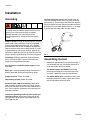
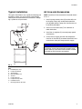
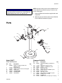
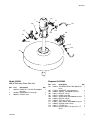
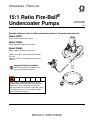
Instructions - Parts List
15:1 Ratio Fire-Ball®
Undercoater Pumps
307879R
Portable stationary units for filled undercoating materials. For professional use only.
Model 222077
35 lb. portable dispense kit and cover
Model 226342
120 lb. rollaround dispense kit and cover
Model 226269
400 lb. stationary dispense kit and cover
2250 psi (15.5 MPa, 155 bar) Maximum Working
Pressure
180 psi (1.2 MPa, 12 bar) Maximum Incoming Air
Pressure
Important Safety Instructions
Read all warnings and instructions in this
manual. Save these instructions.
These systems are designed to be used only in
pumping petroleum-based undercoating materials.
Any other use of the system can cause unsafe
operating conditions and result in component rupture,
fire, or explosion which can cause serious bodily
injury, including fluid injection.
EN
Warnings
Warnings
The following warnings are for the setup, use, grounding, maintenance, and repair of this equipment. The exclamation point symbol alerts you to a general warning and the hazard symbols refer to procedure-specific risks. When
these symbols appear in the body of this manual or on warning labels, refer back to these Warnings. Product-specific
hazard symbols and warnings not covered in this section may appear throughout the body of this manual where
applicable.
WARNING
FIRE AND EXPLOSION HAZARD
When flammable fluids are present in the work area, such as gasoline and windshield wiper fluid, be
aware that flammable fumes can ignite or explode. To help prevent fire and explosion:
• Use equipment only in well ventilated area.
• Eliminate all ignition sources, such as cigarettes and portable electric lamps.
• Keep work area free of debris, including rags and spilled or open containers of solvent and gasoline.
• Do not plug or unplug power cords or turn lights on or off when flammable fumes are present.
• Ground all equipment in the work area.
• Use only grounded hoses.
• Stop operation immediately if static sparking occurs or you feel a shock. Do not use equipment
until you identify and correct the problem.
• Keep a working fire extinguisher in the work area.
SKIN INJECTION HAZARD
High-pressure fluid from dispensing device, hose leaks, or ruptured components will pierce skin. This
may look like just a cut, but it is a serious injury that can result in amputation. Get immediate surgical
treatment.
• Do not point dispensing device at anyone or at any part of the body.
• Do not put your hand over the fluid outlet.
• Do not stop or deflect leaks with your hand, body, glove, or rag.
• Follow the Pressure Relief Procedure when you stop dispensing and before cleaning, checking, or
servicing equipment.
• Tighten all fluid connections before operating the equipment.
• Check hoses and couplings daily. Replace worn or damaged parts immediately.
2
307879R
Warnings
WARNING
EQUIPMENT MISUSE HAZARD
Misuse can cause death or serious injury.
• Do not operate the unit when fatigued or under the influence of drugs or alcohol.
• Do not exceed the maximum working pressure or temperature rating of the lowest rated system component. See Technical Data in all equipment manuals.
• Use fluids and solvents that are compatible with equipment wetted parts. See Technical Data in all
equipment manuals. Read fluid and solvent manufacturer’s warnings. For complete information
about your material, request MSDS from distributor or retailer.
• Turn off all equipment and follow the Pressure Relief Procedure when equipment is not in use.
• Check equipment daily. Repair or replace worn or damaged parts immediately with genuine manufacturer’s replacement parts only.
• Do not alter or modify equipment. Alterations or modifications may void agency approvals and create
safety hazards.
• Make sure all equipment is rated and approved for the environment in which you are using it.
• Use equipment only for its intended purpose. Call your distributor for information.
• Route hoses and cables away from traffic areas, sharp edges, moving parts, and hot surfaces.
• Do not kink or over bend hoses or use hoses to pull equipment.
• Keep children and animals away from work area.
• Comply with all applicable safety regulations.
TOXIC FLUID OR FUMES HAZARD
Toxic fluids or fumes can cause serious injury or death if splashed in the eyes or on skin, inhaled, or
swallowed.
• Read MSDSs to know the specific hazards of the fluids you are using.
• Store hazardous fluid in approved containers, and dispose of it according to applicable guidelines.
PERSONAL PROTECTIVE EQUIPMENT
Wear appropriate protective equipment when in the work area to help prevent serious injury, including
eye injury, hearing loss, inhalation of toxic fumes, and burns. This protective equipment includes but is
not limited to:
• Protective eyewear, and hearing protection.
• Respirators, protective clothing, and gloves as recommended by the fluid and solvent manufacturer
307879R
3
Installation
Installation
Grounding
The equipment must be grounded to reduce the risk
of static sparking and electric shock. Electric or static
sparking can cause fumes to ignite or explode.
Improper grounding can cause electric shock.
Grounding provides an escape wire for the electric
current.
To ground the pump: Remove the ground screw (Z)
and insert through the eye of the ring at the end of the
ground wire (Y). Fasten the ground screw back onto the
pump and tighten securely. Connect the other end of the
groundw ire to a true earth ground. See FIG. 1. To order
a ground wire and clamp, order Part No. 222011.
Z
Pump or sprayer: If using an electrical sprayer, plug the
power supply cord or extension cord, each equipped
with an undamaged three-prong plug, into a properly
grounded outlet. Do not use an adapter. All extensions
cords much have three wires and be rated for 15 amps.
If using another type of sprayer or pump, ground it by
connecting a grounding wire (12 ga minimum) from the
pump or sprayer’s grounding lug to a true earth ground.
Fluid hoses: SUe only electrically conductive hoses
with a maximum of 500 ft. (150 m) combined hose
length to ensure grounding continuity.
FIG. 1
Assembling the Unit
•
Refer to the appropriate parts drawings on pages 7 9 to assemble your unit. Use thread sealant on all
male connections, except at swivels.
•
For models 222077 and 226269: Remove the
cover from the supply drum and install the pump
and cover. Tighten the cover with thumbscrews
•
For model 226342 only: Assemble the dolly. Place
the opened drumo n the dolly. Tighten the nut onto
the carriage bolt to secure the drum.
Air compressor or hydraulic power supply: Follow
local code.
Spray gun : Obtain grounding through connection to a
properly grounded fluid hose and sprayer or pump.
Supply container: Follow local code.
Object being sprayed: Follow local code.
Y
All solvent pails used when flushing: Follow local
code. Use only conductive metal pails, which are conductive. DO not place the pail on a non-conductive surface, such as paper or cardboard, which interrupts the
grounding continuity.
To maintain grounding continuity when flushing or
relieving pressure: always hold a metal part of the
spray gun firmly to the side of a grounded metal pail,
then trigger the gun.
4
307879R
Installation
Typical Installation
Air Line and Accessories
This typical installation is only a guide for selecting and
installing a system. It is not an actual system design.
Contact your Graco distributor for assistance in designing a system to suit your needs.
NOTE: Install the air line accessories in the order shown
in FIG. 2.
D
1. Install a pump runaway valve (G) to shut off the air
to the pump if the pump accelerates beyond the
pre-adjusted setting. A pump that runs too fast can
be seriously damaged.
2. Install an air line lubricator (F) for automatic air
motor lubrication.
3. Install the air regulator (C) to control pump speed
and pressure.
J
G
E
F
C
4. On the main air supply line from the compressor,
install an air line filter (E) to remove harmful dirt and
contaminants from your compressed air supply.
B
NOTICE
H
A
Do not hand air accessories directly on the air inlet.
The fittings are not strong enough to support accessories and may cause one or more to break. Provide
a bracket on which to mount accessories.
FIG. 2
Key:
A
B
C
D
E
F
G
H
J
Fluid Dispense Line
Pump Ground Wire
Air Regulator
Main Air Supply Line
Air Filter
Pump Lubricator
Pump Runaway Vavle
Fluid Drain Valve
Bleed-type Master Air Valve
307879R
5
Operation
Operation
Pressure Relief Procedure
Follow the Pressure Relief Procedure whenever
you see this symbol.
This equipment stays pressurized until pressure is
manually relieved. To help prevent serious injury from
pressurized fluid, such as skin injection, splashing
fluid and moving parts, follow the Pressure Relief
Procedure when you stop spraying and before
cleaning, checking, or servicing the equipment.
2. Open the master air valve from the compressor.
3. For the pump that is connected, trigger the dispense
valve into a grounded metal waste container, making metal-to-metal contact between the container
and valve. Open the bleed-type master air valve and
open the pump air regulator slowly, just until the
pump is running. When the pump is primed and all
the air has been pushed out of the lines, release the
trigger.
4. If you have more than one pump, repear this procedure for each pump.
1. Engage the gun trigger.
NOTE: When the pump is primed, and with sufficient air
supplied, the pump starts when the dispenseing valve is
opened and shuts off when it is closed.
2. Shut off the power supply to the pump and open any
air bleed valves in the system.
5. Set air pressure to each pump at the lowest pressure needed to get the desired results.
3. Disengage the gun trigger stop.
6. Set the air pressure to each pump at the lowest
pressured needed to get desired results.
4. Hold a metal part of the gun girmly to the side of a
grounded metal pail, and trigger the gun to relieve
pressure.
5. Engage the gun trigger to stop.
6. Open the fluid drain valve, and have a container
ready to catch the drainage.
7. Leave the drain valve open until you are ready to
use the system again.
NOTE: If you suspect the gun, hose, or sprayy tip is
completely clogged, or that pressure has not been fully
relieved after following the steps above, very slowly
loosen the tip guard retaining nut, outlet accessory nut,
or hose end coupling, and relieve pressure gradually,
then loosen completely and clear the tip or hose.
Start-up: Single or Multiple
Pump Systems
The maximum workng pressure of each pump in the
system may not be the same size. To reduce the disk
of over-pressurizing any part of your syste, be sure
you know the maximum working pressure rating of
each pump and its connected components. Never
exceed the maximum working pressure of the lowest
rated component connected to a particular pump.
To determine the fluid output pressure using the air
regulator reading, multiply the ratio of the pump by
the air pressure shown on the regulator gauge. For
example:
10:(1) ratio x 100 psi air = 1000 psi fluid output
10:(1) ratio x 0.7 MPa air = 7MPa fluid output
10:(1) ratio x 7 bar air = 70 bar fluid output
Limit the air to the pump so that no air line or fluid line
component or accessory is over-pressurized.
1. Close the air regulators and bleed-type master air
valves to all by one pump.
6
307879R
Operation
NOTICE
Never allow a pump to run dry of fluid being pumped.
A dry pump quickly accelerates to a high speed, possibly damaging itsself, and it may get very hot.
NOTE: A pump runaway valve can be installed on the air
line to automaticaly shut off the pump if it starts to run
too fast. See page 5.
7. Read and follow the instructions supplied with each
component.
8. Whenever you shut off the system always follow the
Pressure Relief Procedure on page 6.
Parts
1
112
111
107
109
101
106
113
102
110
3d
3c
108
114
103
3a
3b
Model 222077
35 lb. Pail Size Unit
Ref.
1
Part
206405
2
3
3a
3b
3c
3d
222079
222058
206522
100220
100916
100922
307879R
Description
Qty.
PUMP, 15:1 Ratio Fire-Ball, See
1
306531 for parts
DISPENSE KIT
1
COVER, includes items 3a through 3d
1
COVER, pail
1
THUMBSCREW
3
LOCKWASHER
2
CAPSCREW
2
Dispense Kit 222079
Ref.
101
Part
109075
102
103
106
107
108
109
110
111
112
113
114
114558
239663
156971
10965
234237
156849
104984
210657
100940
169971
155570
Description
Qty.
AIR REGULATOR, see 308167 for
1
parts
COUPLER, quick disconnect
1
SWIVEL, see 306861 for parts
1
NIPPLE, 1/4 npt
1
HOSE, fluid, cpld
1
SPRAY GUN, see 309092 for parts
1
NIPPLE, 3/8 npt
1
TEE, pipe, 1/4 npt
1
BALL VALVE, see 306861 for parts
1
ELBOW, street, 1/4 npt
1
FITTING, pin
1
UNION, swivel, 1/4 npsm (f) x 1/4 npt (f)
1
7
Operation
Model 226342
120 lb. Drum Size Unit with Dolly
1
3
2
4e
4c
4b
4a
4d
Ref.
1
2
3
4
4a
4b
4c
4d
4e
8
Part
Description
Qty.
206669 PUMP, 15:1 Fire-Ball, See 306531
1
for parts
222079 DISPENSE KIT, see page 7
1
204574 COVER, see 306345 for parts
1
204144 BASE, dolly, includes 4a through 4e 1
100023 WASHER, flat 5/16”
1
100307 NUT, full hex, 3/8-16
1
101851 CASTER, wheel, 2 1/2” dia
4
102971 BOLT, carriage, 3/8-16 x 3”
1
205419 CLAMP, dolly
1
307879R
Operation
112
1
111
109
107
101
110
106
108
113
102
114
103
3
Model 226269
400 lb Stationary Drum Size Unit
Ref.
1
2
3
Part
Description
Qty.
206700 PUMP, 15:1 Fire-Ball, See 306531
1
for parts
222082 DISPENSE KIT, see page
1
200326 COVER, drum
1
307879R
Dispense Kit 222082
Ref.
101
102
103
106
107
108
109
110
111
112
113
114
Part
Description
Qty.
109075 AIR REGULATOR, See 308167 for
1
parts
114558 COUPLER, quick disconnect
1
239663 SWIVEL, see 306861 for parts
1
156971 NIPPLE, 1/4 npt
1
109167 HOSE, fluid, cpld
1
234237 SPRAY GUN, See 309092 for parts 1
156849 NIPPLE, 3/8 npt
1
104984 TEE, pipe, 1/4 npt
1
210657 BALL VALVE, See 306861 for parts 1
100840 ELBOW, street 1/4 npt
1
169971 FITTING, pin
1
155570 UNION, swivel, 1/4 npsm (f) x 1/4
1
npt (f)
9
Graco Standard Warranty
Graco warrants all equipment referenced in this document which is manufactured by Graco and bearing its name to be free from defects in
material and workmanship on the date of sale to the original purchaser for use. With the exception of any special, extended, or limited warranty
published by Graco, Graco will, for a period of twelve months from the date of sale, repair or replace any part of the equipment determined by
Graco to be defective. This warranty applies only when the equipment is installed, operated and maintained in accordance with Graco’s written
recommendations.
This warranty does not cover, and Graco shall not be liable for general wear and tear, or any malfunction, damage or wear caused by faulty
installation, misapplication, abrasion, corrosion, inadequate or improper maintenance, negligence, accident, tampering, or substitution of
non-Graco component parts. Nor shall Graco be liable for malfunction, damage or wear caused by the incompatibility of Graco equipment with
structures, accessories, equipment or materials not supplied by Graco, or the improper design, manufacture, installation, operation or
maintenance of structures, accessories, equipment or materials not supplied by Graco.
This warranty is conditioned upon the prepaid return of the equipment claimed to be defective to an authorized Graco distributor for verification of
the claimed defect. If the claimed defect is verified, Graco will repair or replace free of charge any defective parts. The equipment will be returned
to the original purchaser transportation prepaid. If inspection of the equipment does not disclose any defect in material or workmanship, repairs will
be made at a reasonable charge, which charges may include the costs of parts, labor, and transportation.
THIS WARRANTY IS EXCLUSIVE, AND IS IN LIEU OF ANY OTHER WARRANTIES, EXPRESS OR IMPLIED, INCLUDING BUT NOT LIMITED
TO WARRANTY OF MERCHANTABILITY OR WARRANTY OF FITNESS FOR A PARTICULAR PURPOSE.
Graco’s sole obligation and buyer’s sole remedy for any breach of warranty shall be as set forth above. The buyer agrees that no other remedy
(including, but not limited to, incidental or consequential damages for lost profits, lost sales, injury to person or property, or any other incidental or
consequential loss) shall be available. Any action for breach of warranty must be brought within two (2) years of the date of sale.
GRACO MAKES NO WARRANTY, AND DISCLAIMS ALL IMPLIED WARRANTIES OF MERCHANTABILITY AND FITNESS FOR A
PARTICULAR PURPOSE, IN CONNECTION WITH ACCESSORIES, EQUIPMENT, MATERIALS OR COMPONENTS SOLD BUT NOT
MANUFACTURED BY GRACO. These items sold, but not manufactured by Graco (such as electric motors, switches, hose, etc.), are subject to
the warranty, if any, of their manufacturer. Graco will provide purchaser with reasonable assistance in making any claim for breach of these
warranties.
In no event will Graco be liable for indirect, incidental, special or consequential damages resulting from Graco supplying equipment hereunder, or
the furnishing, performance, or use of any products or other goods sold hereto, whether due to a breach of contract, breach of warranty, the
negligence of Graco, or otherwise.
FOR GRACO CANADA CUSTOMERS
The Parties acknowledge that they have required that the present document, as well as all documents, notices and legal proceedings entered into,
given or instituted pursuant hereto or relating directly or indirectly hereto, be drawn up in English. Les parties reconnaissent avoir convenu que la
rédaction du présente document sera en Anglais, ainsi que tous documents, avis et procédures judiciaires exécutés, donnés ou intentés, à la suite
de ou en rapport, directement ou indirectement, avec les procédures concernées.
Graco Information
For the latest information about Graco products, visit www.graco.com.
TO PLACE AN ORDER, contact your Graco distributor or call to identify the nearest distributor.
Phone: 612-623-6928 or Toll Free: 1-800-533-9655, Fax: 612-378-3590.
All written and visual data contained in this document reflects the latest product information available at the time of publication.
Graco reserves the right to make changes at any time without notice.
For patent information, see www.graco.com/patents.
Original instructions. This manual contains English. MM 307879
Graco Headquarters: Minneapolis
International Offices: Belgium, China, Japan, Korea
GRACO INC. AND SUBSIDIARIES • P.O. BOX 1441 • MINNEAPOLIS MN 55440-1441 • USA
Copyright 1998, Graco Inc. All Graco manufacturing locations are registered to ISO 9001.
www.graco.com
Revised January 2013