1
AQUA SOLAR
TM
Electronic Solar Control Center
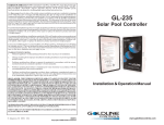
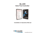
Operation and Installation Manual
for models
AQ-SOL-LV
AQ-SOL-LV-TC
AQ-SOL-LV-SP
G
LDLINE
C ON TROLS
www.goldlinecontrols.com
Table of Contents
SPECIFICATIONS
Specifications ......................................................................1
OPERATION
Controls ...............................................................................2
Temperature Display ........................................................3
INSTALLATION
Mounting ..............................................................................4
Wiring ..................................................................................4
Jumper Settings ..................................................................9
TROUBLESHOOTING
Troubleshooting ..............................................................10
WARRANTY
Five Year Limited Warranty
Warranty...........................................12
IMPORTANT SAFETY INSTRUCTIONS
When using this electrical equipment, basic safety precautions should always be
followed, including the following:
•
READ AND FOLLOW ALL INSTRUCTIONS
•
Disconnect all AC power during installation.
•
Warning – To reduce the risk of injury do not permit children to use this
product unless they are closely supervised at all times.
•
A green colored terminal marked “EARTH” is located inside the wiring
compartment. To reduce the risk of electrical shock, this terminal must
be connected to the grounding means provided in the electrical supply
service panel with a continuous copper wire equivalent in size to the
circuit conductors supplying the equipment.
•
All field installed metal components such as rails, ladders, drains, or
other similar hardware within 3 meters of the pool, spa or hot tub shall be
bonded to the equipment grounding bus with copper conductors not
smaller than 8 AWG US/ 6 AWG Canada.
SAVE THESE INSTRUCTIONS
Aqua Solar Digital Solar Control System
The Aqua Solar Digital Solar Control System is a differential temperature control for
solar heating of pools, spas, and hot tubs. The Aqua Solar is available in 3 models;
AQ-SOL-LV, AQ-SOL-LV-TC and AQ-SOL-LV-SP. These models provide differential temperature control with an adjustable calibrated water temperature high limit.
Both offer a built-in digital display for solar, water, and ambient temperature information as well as programmable set point temperature. Automatic nocturnal cooling
(for pools that overheat in hot climates) and recirculate freeze protection functions
can be enabled/disabled via internal jumpers. The AQ-SOL-LV-TC additionally provides a filter pump time clock, programmable in 15-minute intervals with multiple
ON/OFF times. The AQ-SOL-LV-SP model provides a solar priority function—one
of the optional high voltage relays can be used to remove power from the conventional heater whenever solar heating is available. This maximizes the heat contribution from solar. Front panel indicator LED’s also provide immediate feedback of
system state such as heating, cooling, and sensor fault.
Specifications
Power:
105-130VAC, .5A 50/60Hz. or
195-250VAC, .3A 50/60Hz
Valve Output: 24VAC, 20VA, .85A max.
Industry standard 3 pin connector
Relay Outputs: DPST isolated contacts; 3HP@240V, 1.5HP@120V, booster
pump, pool sweep interlock, or filter pump; 1 relay supplied with
AQ-SOL-LV-TC, maximum of 2; order relays separately (part no.
AQ-RELAY); relays are industry standard
Sensors:
2 required for "SOLAR" and "POOL" temperatures; 3rd sensor
("AUX") is optional—for display and/or recirculate freeze
protection; (all sensors are thermistor type, 10K@25ºC/77ºF,
additional freeze snap switches may be wired in series with the
"AUX" sensor when used for recirculate freeze protection)
Field Selectable options
C/F
Cooling
Recirc. Frz.
Solar Override
Temperature display in Celsius or Fahrenheit (factory default)
Enables or disables (factory default) operation to cool the pool
Enables or disables (factory default) recirculate freeze protection
Enables or disables (factory default) override of the filter pump
relay when solar heat is available.
Control Logic
Heat diff.:
4ºF on, 1.5ºF off
High Limit:
70-104ºF calibrated scale
Recirc. freeze: On when AUX sensor less than or equal to 34ºF
Off when AUX sensor greater than or equal to 36ºF
Cool diff.:
-8ºF on, -3ºF off
1
OPERATION
The Aqua Solar is a fully automatic solar heating control which requires minimal set
up or adjustment under normal operating conditions. Typically the following is
required:
1.
2.
3.
Set the main switch to AUTO
Set the “Desired Temperature” knob to the desired temperature for the pool
Set the time clock for the correct time, the desired hours of filtration, and
“auto” operation (model AQ-SOL-LV-TC only)
The “Heating” LED will show when the pool is being solar heated. If your pool has
a pool sweep, the Aqua Solar will turn it off for approximately 6 minutes when solar
heat is turned on. This will allow air to be purged from the system.
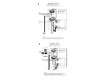
Controls and Displays
MAIN SWITCH
ON: The Aqua Solar directs water through the solar collectors regardless of
desired temperature setting. Both the “Heating” and “Cooling” LED’s will
be on. For model AQ-SOL-LV-TC, this also turns on the filter pump.
AUTO: For normal operation. In this position, the Aqua Solar will operate
automatically based on the solar and pool temperatures.
OFF: The Aqua Solar ceases solar heating or cooling (if enabled). Recirculate freeze protection (if enabled) will still operate normally. This switch
does NOT remove power from the unit--to service the equipment, disconnect
power at the main circuit breaker.
DESIRED TEMPERATURE
Set the desired pool temperature. The digital display will show the exact temperature while rotating the Desired Temperature knob. The display reverts back to the
default pool temperature display a few seconds later.
TIMECLOCK (model AQ-SOL-LV-TC only)
The time clock controls the hours of operation for the filter pump. The pump can
be programmed in 15-minute intervals with multiple on/off periods per day. Per
NSPI standards, the pump should run long enough each day to filter all of the
water in the pool each day.
Set the Aqua Solar timeclock to the correct time by rotating the clock dial in a
clockwise direction. The internal “hands” show time at a glance and the arrow
(approximately 2 o’clock on dial) point indicates AM/PM. Set the pump on/off
time using the series of small slide "trippers" located around the outside of the
timeclock. Each tripper controls a 15-minute interval.
OFF - Push trippers IN (toward center)
ON - Pull trippers OUT (away from center)
2
TIME CLOCK -- MANUAL CONTROL
The manual control can override the timer and is located at approximately the 4
o’clock position.
“1” (up)
- pump ON
“ ” (center) - timer controls pump
“0” (down) - pump OFF
NOTE: If the solar override function is enabled, then the Aqua Solar may keep the
filter pump running even though the time clock is “off”
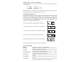
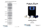
TEMPERATURE DISPLAY
The temperature display normally displays the pool temperature. Push the small
button next to the display to cycle through the various displays. If a temperature
sensor is not wired to the Aqua Solar, or the sensor is not functioning properly, the
error message "Err" will be displayed for that sensor. If the button is not pushed for
30 seconds, the display will automatically revert back to pool temperature. The
example below shows a typical display:
Normal, default display indicates Pool temperature:
1st button push will show Solar Collector temperature:
2nd button push will show Aux temperature (if used):
3rd button push will show "Desired Temperature":
4th button push will show software revision number:
5th button push will loop back to show Pool temperature.
LED INDICATORS
Power:
Input power is applied to the Aqua Solar.
Heating:
Solar heating is active. If both Heating and Cooling are on,
the switch is in the ON position.
Cooling:
Nocturnal Cooling is active. If both Heating and Cooling are
on, the switch is in the ON position.
Sweep Interlock:
The pool sweep is turned OFF for approximately 6 minutes
to allow air to purge from the system.
Pool Sensor:
A problem is detected with the pool sensor (open or short
circuit).
Solar Sensor:
A problem is detected with solar sensor (open or short circuit).
Aux Sensor:
A problem is detected with the AUX sensor (short circuit,
only when used for recirculate freeze protection).
3
INSTALLATION
Mounting
The Aqua Solar is designed for outdoor use. Mount the enclosure vertically with the
knockouts facing downward. For safety, the Aqua Solar must be a minimum of 5
feet (horizontally) from the pool or spa.
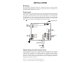
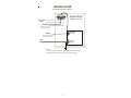
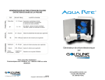
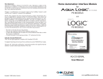
Power input
Turn off power at circuit breaker before wiring. Follow NEC and all local electrical
codes. Wire to either 120VAC or 240VAC per the diagram below. If the Aqua Solar
is being powered from the same circuit as one of the pumps, wire to the relay first
and then jumper over the Aqua Solar terminal block. Do NOT use the Aqua Solar
terminal block as a junction for pump power, the terminal block is not rated for high
amps. Be sure to connect the earth ground to the green terminal.
Fuse (2A, Slo-Blo)
Relay
Control
Outputs
Booster Pump
Pool Sweep (heater interlock for -SP model)
Filter Pump
Rev
Input
Power
Solar Pool Aux
Fwd
120VAC
240 VAC
Ground
}
Valve
Output
Temperature
Sensor
Inputs
Cooling
Recirculate/
Freeze Protection
Celsius/
Fahrenheit
Solar
Override
Output wiring to solar diverter valve
Most installations use a solar valve, which diverts
water
through the® collector panels
®
®
when solar heat is available. For Goldline , Jandy , and Compool valve actuators
(with wire end connectors), two 3-pin connectors are supplied. Plug the actuator
into one of the Aqua Solar's two 3-pin connectors (see diagram above for location of
connectors). If the valve operates opposite to the way it is supposed to, disconnect
and plug into the other connector.
®
Jandy is a registered trademark of Waterpik Technologies, Inc.
®
Compool is a registered trademark of Pentair Pool Products, Inc.
4
Sensor Mounting and Wiring
Most installations use a Goldline "PC" type sensor for both the "SOLAR" sensor
and "POOL" sensors. The "AUX" sensor is required for optional recirculate
freeze protection (see description of this function on page 9). Otherwise, the
"AUX" sensor can simply display the ambient air temperature.
Any 10K ohm Goldline sensors may be used. Wire should be twisted pair 20AWG.
Sensor wiring run outdoors must be rated for outdoor use and ensure that the wire
connectors are protected from the weather. For long runs or runs near other electrical wiring use shielded cable (Belden 8428 for outdoor use). Ground the shields to
the Aqua Solar's ground screw.
High Voltage Relay Output Wiring
A maximum of two high voltage relays (industry standard) may be added to the
AQ-SOL-LV. The AQ-SOL-LV-TC model comes with one relay for the filter pump
control already installed and one additional relay may be added. Order additional
relays separately (Goldline p/n "AQ-RELAY"). The relays are industry standard
and are double pole, single throw meaning that they can make/break both legs of a
240VAC circuit. Screw the relays into the mounting bracket and connect the coil
to the proper connector for these desired functions:
BOOST: This relay controls a booster pump for systems where the main filter
pump does not have enough power to pump water through the collector array. The
boost pump turns on 30 seconds after solar heating/cooling turns on.
AQ-SOL-LV: For most systems, simply connect the Aqua Solar power to the
LOAD side of the filter pump timer. If the Aqua Solar is connected to LINE power
(typically when "Recirculate Freeze" or "Solar Override" features are also being
used), then the input power to the boost pump relay should be connected to the
LOAD side of the filter pump timer. See wiring diagram on page 6 (bottom).
AQ-SOL-LV-TC: The Aqua Solar will automatically ensure that the filter pump is
running before turning on the boost pump. See wiring diagram on page 7.
SWEEP INTERLOCK: The relay is wired in series with the pool sweep and
turns the pool sweep off for approximately 6 minutes whenever the solar turns on.
This prevents the pool sweep pump from losing prime while air is being purged
from the solar collector array. For model, AQ-SOL-LV-TC the relay will also turn
the pool sweep off whenever the filter pump is turned off. See wiring diagrams on
page 6 (top) and on page 7 (bottom) for typical wiring.
FILTER PUMP: The function of this relay varies with the model of the Aqua
Solar. If the "Solar Override" is enabled (see "Jumper Settings"), the Aqua Solar
will override the time clock and turn the filter pump on when there is a call for
solar heating. If "Recirculate Freeze" protection is enabled, the Aqua Solar will
turn the pump and solar valve on during freezing conditions.
AQ-SOL-LV: This relay should be wired in parallel with the filter pump timeclock
contacts as shown on page 6. Be careful to make sure the phases do not get reversed.
AQ-SOL-LV-TC: This relay is the primary control for the filter pump—there is no
other timer. The Aqua Solar will operate the filter pump according to the "trippers"
set on the built-in timeclock in addition to the optional "Solar Override" and "Recirculate Freeze" options.
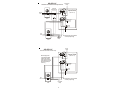
5
AQ-SOL-LV
with Solar Override & Pool Sweep Interlock
Pool Sweep
Pump
Contactor
(240 VAC Coil)
Aqua Solar
(AQ-SOL-LV)
120/240
VAC
Pool Sweep
Timer
Booster Pump
Pool Sweep
Filter Pump
240 VAC
Ground
240
VAC
Be careful not to cross phases
on filter pump wiring
Filter Pump
Timer
Pool Filter
Pump
Boost
Pump
AQ-SOL-LV
with Solar Override & Boost Pump
Aqua Solar
(AQ-SOL-LV)
Boost relay power
connected to LOAD
side of Filter Pump
Timer to ensure that
boost pump only runs
when filter pump is
runnning
Booster Pump
Pool Sweep
Filter Pump
240 VAC
Ground
240
VAC
Be careful not to cross phases
on filter pump wiring
Filter Pump
Timer
Pool Filter
Pump
6
AQ-SOL-LV-TC
with filter pump & booster pump relays
Aqua Solar
(AQ-SOL-LV-TC)
240
VAC
Booster Pump
Pool Sweep
Filter Pump
240
VAC
240 VAC
Ground
Filter
Pump
Solar
Booster
Pump
NOTES:
1) Do not use Aqua Solar terminal block as a junction for pump wiring.
2) Most codes require that each pump be on a separate circuit.
AQ-SOL-LV-TC
with filter pump & pool sweep relays
Aqua Solar
(AQ-SOL-LV-TC)
120/240
VAC
Pool Sweep
Timer
Booster Pump
Pool Sweep
Filter Pump
240
VAC
240 VAC
Ground
Sweep
Pump
Filter
Pump
NOTES:
1) Do not use Aqua Solar terminal block as a junction for pump wiring.
2) Most codes require that each pump be on a separate circuit.
3) Aqua Solar will ensure sweep pump runs only when filter pump is running.
4) Sweep pump will turn off for approximately 5 minutes when solar turns on.
7
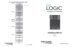
AQ-SOL-LV-SP
HEATER INTERLOCK FUNCTION
Aqua Solar
(AQ-SOL-LV-SP)
120 or 240
VAC
HEATER
when solar off
(On
Off when solar on )
Booster Pump
Pool Sweep
Filter Pump
NOTE:
Connect heater interlock
relay to“Pool Sweep”
240
VAC
240 VAC
Ground
NOTES:
1) Do not use Aqua Solar terminal block as a junction for pump wiring.
2) Most codes require that each pump be on a separate circuit.
8
Jumper Settings
The jumpers that enable/disable optional control features are located on the right
side of the main circuit board (see page 4). The factory default for all functions is
"disabled" (each jumper will be on a single pin). To "enable" a function, simply take
the designated jumper and place it over both pins.
COOLING: A high voltage relay for filter pump control is usually required to
implement this function. If Cooling is enabled, the Aqua Solar will cool the pool by
turning on the filter pump and diverting the flow through the collector array whenever the "POOL" temperature is WARMER than the “Desired Temperature” setting
AND the "SOLAR" sensor is COOLER than the pool water.
RECIRCULATE FREEZE PROTECTION: A high voltage relay connected to
the "FILTER PUMP" output and the AUX temperature sensor are required to implement this function. If enabled, the Aqua Solar will turn the filter pump on and operate the solar diverter valve whenever freezing conditions are detected (AUX sensor
below 35ºF). See diagram on page 6 for typical relay wiring. When recirculate
freeze protection is enabled and the Aqua Solar senses a freeze condition at the AUX
sensor, it will circulate the pool water continuously through the entire filtration plumbing loop including the solar collector panels. While this type of freeze protection is
usually adequate in relatively mild climates, it is extremely important that the AUX
sensor be properly placed and that the homeowner realize that the system is unprotected in the event of a power failure. Goldline Controls highly recommends that
one or more “freeze snap switches” (model GC-3) be placed in areas with susceptible plumbing (example: areas that may be shaded, or get more wind exposure) and
that these sensors be wired in series with the AUX sensor. Recirculate freeze protection is NOT recommended in climates where freezing temperatures are common or last for extended periods.
WARNING--If recirculate freeze protection is NOT selected, then you are relying on the collectors naturally draining to provide freeze protection. It is very
important that you use a non-positive seal valve or drill a hole in the diverter of
a positive seal valve to allow the collectors to drain. This will NOT work if the
collectors are located below the water level of the pool.
CELSIUS DISPLAY: This will change the temperature display to degrees--Celsius. The factory default is degrees--Fahrenheit.
SOLAR OVERRIDE: A high voltage relay connected to the "FILTER PUMP"
output is required to implement this function. When "Solar Override" is enabled,
the Aqua Solar will override the filter pump timeclock (external timeclock for AQSOL-LV or internal timeclock for AQ-SOL-LV-TC) and turn the filter pump on whenever there is a call for solar heating or cooling. During periods of on/off cloudy days
this may result in the pump turning on and off multiple times. It is also possible that
the pump could turn on during hot night conditions. To prevent rapid on/off cycling
of the filter pump during cloudy conditions, the pump will also remain on for a
minimum of 10 minutes, and will remain off for a minimum of 2 hours.
9
Troubleshooting
1. "Power" LED off:
Check main power circuit breakers. Check to see if the Aqua Solar power is connected to the LOAD side of the filter pump timer, in which case the Aqua Solar will
only be on when the filter pump is on. Lastly, check the internal fuse which is
located on the right upper side of the main circuit board. If necessary, replace the
fuse with a type 3AG, 2 amp, slo-blo fuse, which is available in most electrical or
electronics stores.
2. "Heating" LED is always on:
Check that the switch is in the “AUTO” position. Check the sensor temperatures:
The "Heating" LED should go off if the pool temperature is less than the "Desired
Temperature" OR if the solar temperature is less than the pool temperature. If the
sensors appear to giving incorrect readings, check the sensors using the temperature/
resistance/voltage chart on the back cover.
3. "Heating" LED never comes on:
Verify that the switch is in the “AUTO” position. Check the sensor temperatures:
The "Heating" LED should turn on when the pool temperature is less than the "Desired Temperature" AND the solar temperature is warmer than the pool temperature.
The exception is when solar override is being used (typically when the pool is filtered at night, but the solar override function is used to turn the filter pump on during
the day when solar heat is available): In this case, there is a 2 hour minimum off time
to prevent rapid on/off cycling of the filter pump. If the sensors appear to giving
incorrect readings, check the sensors using the temperature/resistance/voltage chart
on the back cover.
4. "Heating" and "Cooling" LEDs on simultaneously
This indicates that the main switch is in the "ON" position. The Aqua Solar will
operate the solar valve and the booster pump (if installed) regardless of the sensor
temperatures. Set the switch back to "AUTO" to resume normal operation.
5. "Heating" and "Cooling" LEDs flashing simultaneously
This indicates that recirculate freeze protection is active (solar valve on, boost pump
on (if used), and filter pump on) due to the "AUX" sensor being less than 35ºF OR
the "AUX" sensor being disconnected OR any freeze snap switches wired in series
with the "AUX" sensor being open. If the "AUX" sensor is not connected OR a
freeze snap switch is open, the "AUX" temperature display will be " LO ". The Aqua
Solar will continue this operating mode until the "AUX" sensor rises above 35ºF
AND all freeze snap switches wired in series with the "AUX" sensor are closed.
This function operates regardless of the position of the "ON / AUTO / OFF" switch.
6. "Pool Sensor" LED on or flashing
"Err" on the pool temperature display:
On continuously indicates a probable open circuit in the "POOL" sensor or wiring.
Flashing indicates a probable short circuit in the "POOL" sensor or wiring. In either
case digital pool temperature display will show as "PErr". The solar heating and
cooling functions will remain off until this problem is fixed, however, the recirculate
freeze protection (if enabled by the jumper) will still operate properly. Use the chart
on
10
the back cover to check the "POOL" sensor with a voltmeter (you don't need to
disconnect the sensor). Alternatively, you can disconnect the sensor and measure
the sensor resistance. Replace the sensor or fix the wiring as required. If the sensor
and wiring are both good, then the main circuit PCB may have a problem.
7. "Solar Sensor" LED on or flashing
"Err" on the solar temperature display:
On continuously indicates a probable open circuit in the "SOLAR" sensor or wiring.
Flashing indicates a probable short circuit in the "SOLAR" sensor or wiring. In
either case digital pool temperature display for the "SOLAR" sensor will show as
"CErr". The solar heating and cooling functions will remain off until this problem is
fixed, however, the recirculate freeze protection (if enabled by the jumper) will still
operate properly.
Use the chart on the back cover to check the "SOLAR" sensor with a voltmeter (you
don't need to disconnect the sensor). Alternatively, you can disconnect the sensor
and measure the sensor resistance. Replace the sensor or fix the wiring as required.
If the sensor and wiring are both good, then the main circuit PCB may have a problem.
8. "Aux Sensor" LED flashing
"Err" on the Aux temperature display:
Flashing indicates a probable short circuit in the "AUX" sensor or wiring. The digital pool temperature display for the "AUX" sensor will show as "AErr". This error
indication only occurs when the "AUX" sensor is being used for recirculate freeze
protection. When the Aux sensor is shorted, the Aqua Solar will use the "SOLAR"
sensor as a backup freeze sensor and turn the recirculate freeze protection on when
the temperature is less than 60ºF.
Use the chart on the back cover to check the "AUX" sensor with a voltmeter (you
don't need to disconnect the sensor). Alternatively, you can disconnect the sensor
and measure the sensor resistance. Replace the sensor or fix the wiring as required.
If the sensor and wiring are both good, then the main circuit PCB may have a problem.
11
LIMITED WARRANTY Goldline warrants its Aqua Rite, Aqua Rite Pro, Aqua Trol, Aqua Logic and
Pro Logic products (products with Goldline part numbers starting with AQ-RITE-, AQ-RT-PRO, AQTROL-, AQ-LOGIC-, AQL-P-, AQL-PS-, AQL-CL-, PL-P-, PL-PS-, and HPC-2) to be free from defects
in material or workmanship, under normal use and service:
For three years from the date of the initial system installation on private, residential swimming pools
within the USA or Canada and one year from the date of initial system installation on commercial
installations, installations outside of the USA or Canada and for any replacement parts or accessory
products, provided they are installed in accordance with the Goldline installation instructions and specifications provided with the product. If written proof of the date of the initial system installation is not
provided to Goldline, the manufacturing datecode on the Aqua Rite, Aqua Rite Pro, Aqua Trol, Aqua
Logic and Pro Logic electronics unit will be the sole determinant of the date of the initial system installation.
For residential installations in USA or Canada: If a product is defective in workmanship or materials and
is removed and returned freight prepaid within three (3) years after the date of the initial system installation, Goldline will, at its option, either repair or replace the defective product and return it freight prepaid.
For commercial installations, installations outside the USA and Canada, and accessory products and
replacement parts: If a product is defective in workmanship or materials and is removed and returned
freight prepaid within one (1) year after the date of the initial system installation, Goldline will, at its
option, either repair or replace the defective product and return it freight prepaid.
Contact any Goldline dealer or contact Goldline at 61 Whitecap Drive, North Kingstown, RI 02852 for
warranty service. The costs incurred in removal and/or reinstallation of the product are NOT covered
under this warranty. Some states do not allow limitations on how long an implied warranty lasts, so the
above limitation may not apply to you.
WARRANTY EXCLUSIONS:
1.
Material supplied or workmanship performed by others in process of installation.
2.
Damage resulting from improper installation including installation on pools larger than the product rating.
3.
Problems resulting from failure to operate the product(s) in accordance with the recommended
instructions contained in product’s owners manual(s).
4.
Problems resulting from failure to maintain pool water chemistry in accordance with the recommendations in the owners manual(s).
5.
Problems resulting from tampering, accident, abuse, negligence, unauthorized repairs or alternations, fire, flood, lightning, freezing, external water, degradation of natural stone used in or immediately adjacent to a pool or spa, war or acts of God.
DISCLAIMER. THE EXPRESS LIMITED WARRANTY ABOVE CONSTITUTES THE ENTIRE WARRANTY OF GOLDLINE WITH RESPECT TO ITS POOL AUTOMATION AND
CHLORINATION PRODUCTS AND IS IN LIEU OF ALL OTHER WARRANTIES, EXPRESSED
OR IMPLIED, INCLUDING WARRANTIES OF MERCHANTABILITY OR FITNESS FOR A
PARTICULAR PURPOSE. THIS WARRANTY GIVES YOU SPECIFIC LEGAL RIGHTS, AND
YOU MAY ALSO HAVE OTHER RIGHTS WHICH VARY FROM STATE TO STATE. IN NO
EVENT SHALL GOLDLINE BE RESPONSIBLE FOR ANY CONSEQUENTIAL, SPECIAL OR
INCIDENTAL DAMAGES OF ANY NATURE WHATSOEVER, INCLUDING, BUT NOT LIMITED TO, PERSONAL INJURY, PROPERTY DAMAGE, DAMAGE TO OR LOSS OF EQUIPMENT, LOST PROFITS OR REVENUE, COSTS OF RENTING REPLACEMENTS, AND
OTHER ADDITIONAL EXPENSES, EVEN IF THE SELLER HAD BEEN ADVISED OF THE
POSSIBILITY OF SUCH DAMAGES. SOME STATES DO NOT ALLOW THE EXCLUSION
OF LIMITATION OF INCIDENTAL OR CONSEQUENTIAL DAMAGES, SO THE ABOVE
LIMITATION OR EXCLUSION MAY NOT APPLY TO YOU.
NO WHOLESALER, AGENT, DEALER, CONTRACTOR OR OTHER PERSON IS AUTHORIZED TO GIVE ANY WARRANTY ON BEHALF OF GOLDLINE.
THIS WARRANTY IS VOID IF THE PRODUCT HAS BEEN ALTERED IN ANY WAY AFTER
LEAVING THE FACTORY.
12
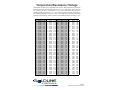
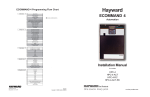
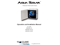
Temperature/Resistance /Voltage
All Goldline controls use a 10K thermistor sensors. When disconnected from the
control, the sensor will read 10K ohms at 25ºC/77ºF. Refer to the chart below for
the resistance at other temperatures. For a given temperature, the resistance
reading should be accurate to ±1%. For a given resistance reading, the temperature reading should be accurate to ±0.5ºF. All voltage measurements (DC) must
be made with the sensor connected to the control and should be accurate to ± 2%.
°F
1
2
3
4
5
6
7
8
9
10
11
12
13
14
15
16
17
18
19
20
21
22
23
24
25
26
27
28
29
30
31
32
33
34
35
36
37
38
39
40
G
Ohms
82,719
80,142
77,656
75,255
72,937
70,698
68,535
66,447
64,428
62,479
60,595
58,774
57,014
55,313
53,669
52,078
50,541
49,054
47,616
46,225
44,879
43,577
42,318
41,099
39,919
38,777
37,671
36,601
35,565
34,561
33,590
32,648
31,737
30,853
29,998
29,169
28,365
27,587
26,832
26,100
Volts
4.46
4.45
4.43
4.41
4.40
4.38
4.36
4.35
4.33
4.31
4.29
4.27
4.25
4.23
4.21
4.19
4.17
4.15
4.13
4.11
4.09
4.07
4.04
4.02
4.00
3.97
3.95
3.93
3.90
3.88
3.85
3.83
3.80
3.78
3.75
3.72
3.70
3.67
3.64
3.61
°F
41
42
43
44
45
46
47
48
49
50
51
52
53
54
55
56
57
58
59
60
61
62
63
64
65
66
67
68
69
70
71
72
73
74
75
76
77
78
79
80
Ohms
25,391
24,704
24,037
23,391
22,764
22,156
21,566
20,993
20,438
19,900
19,377
18,870
18,377
17,899
17,435
16,985
16,548
16,123
15,711
15,310
14,921
14,543
14,176
13,820
13,473
13,136
12,809
12,491
12,182
11,882
11,589
11,305
11,029
10,761
10,500
10,246
9,999
9,758
9,525
9,297
Volts
3.59
3.56
3.53
3.50
3.47
3.45
3.42
3.39
3.36
3.33
3.30
3.27
3.24
3.21
3.18
3.15
3.12
3.09
3.06
3.02
2.99
2.96
2.93
2.90
2.87
2.84
2.81
2.78
2.75
2.72
2.68
2.65
2.62
2.59
2.56
2.53
2.50
2.47
2.44
2.41
°F
81
82
83
84
85
86
87
88
89
90
91
92
93
94
95
96
97
98
99
100
101
102
103
104
105
106
107
108
109
110
111
112
113
114
115
116
117
118
119
120
Ohms
9,076
8,861
8,651
8,447
8,249
8,056
7,867
7,684
7,506
7,333
7,164
6,999
6,839
6,683
6,530
6,382
6,238
6,097
5,960
5,827
5,697
5,570
5,446
5,326
5,208
5,094
4,982
4,873
4,767
4,664
4,563
4,464
4,368
4,274
4,183
4,094
4,007
3,922
3,839
3,758
Volts
2.38
2.35
2.32
2.29
2.26
2.23
2.20
2.17
2.14
2.12
2.09
2.06
2.03
2.00
1.98
1.95
1.92
1.89
1.87
1.84
1.81
1.79
1.76
1.74
1.71
1.69
1.66
1.64
1.61
1.59
1.57
1.54
1.52
1.50
1.47
1.45
1.43
1.41
1.39
1.37
°F
121
122
123
124
125
126
127
128
129
130
131
132
133
134
135
136
137
138
139
140
141
142
143
144
145
146
147
148
149
150
151
152
153
154
155
156
157
158
159
160
Ohms
3,679
3,602
3,527
3,454
3,382
3,312
3,244
3,177
3,112
3,049
2,987
2,926
2,867
2,809
2,752
2,697
2,643
2,591
2,539
2,489
2,440
2,392
2,345
2,299
2,254
2,210
2,167
2,125
2,084
2,044
2,005
1,966
1,929
1,892
1,856
1,821
1,787
1,753
1,720
1,688
Volts
1.34
1.32
1.30
1.28
1.26
1.24
1.22
1.21
1.19
1.17
1.15
1.13
1.11
1.10
1.08
1.06
1.05
1.03
1.01
1.00
0.98
0.97
0.95
0.93
0.92
0.90
0.89
0.88
0.86
0.85
0.84
0.82
0.81
0.80
0.78
0.77
0.76
0.75
0.73
0.72
LDLINE
C ON TROLS
N. Kingstown, RI 02852 USA
092008E
Copyright © 2008 Goldine Controls