1
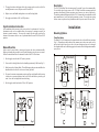
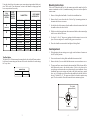
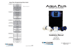
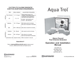
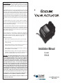
LIMITED WARRANTY Goldline warrants its Aqua Rite, Aqua Rite Pro, Aqua Trol, Aqua
Logic and Pro Logic products (products with Goldline part numbers starting with AQ-RITE, AQ-RT-PRO, AQ-TROL-, AQ-LOGIC-, AQL-P-, AQL-PS-, AQL-CL-, PL-P-, PL-PS-,
and HPC-2) to be free from defects in material or workmanship, under normal use and
service:
For three years from the date of the initial system installation on private, residential
swimming pools within the USA or Canada and one year from the date of initial system
installation on commercial installations, installations outside of the USA or Canada and for
any replacement parts or accessory products, provided they are installed in accordance with
the Goldline installation instructions and specifications provided with the product. If
written proof of the date of the initial system installation is not provided to Goldline, the
manufacturing datecode on the Aqua Rite, Aqua Rite Pro, Aqua Trol, Aqua Logic and Pro
Logic electronics unit will be the sole determinant of the date of the initial system installation.
For residential installations in USA or Canada: If a product is defective in workmanship or
materials and is removed and returned freight prepaid within three (3) years after the date
of the initial system installation, Goldline will, at its option, either repair or replace the
defective product and return it freight prepaid.
For commercial installations, installations outside the USA and Canada, and accessory
products and replacement parts: If a product is defective in workmanship or materials and
is removed and returned freight prepaid within one (1) year after the date of the initial
system installation, Goldline will, at its option, either repair or replace the defective
product and return it freight prepaid.
Contact any Goldline dealer or
RI 02852 for warranty service.
product are NOT covered under
long an implied warranty lasts,
contact Goldline at 61 Whitecap Drive, North Kingstown,
The costs incurred in removal and/or reinstallation of the
this warranty. Some states do not allow limitations on how
so the above limitation may not apply to you.
WARRANTY EXCLUSIONS:
1.
Material supplied or workmanship performed by others in process of installation.
2.
Damage resulting from improper installation including installation on pools larger
than the product rating.
3.
Problems resulting from failure to operate the product(s) in accordance with the
recommended instructions contained in product’s owners manual(s).
4.
Problems resulting from failure to maintain pool water chemistry in accordance with
the recommendations in the owners manual(s).
Installation Manual
5.
Problems resulting from tampering, accident, abuse, negligence, unauthorized repairs
or alternations, fire, flood, lightning, freezing, external water, degradation of natural
stone used in or immediately adjacent to a pool or spa, war or acts of God.
for model
GVA-24
DISCLAIMER. THE EXPRESS LIMITED WARRANTY ABOVE CONSTITUTES THE
ENTIRE WARRANTY OF GOLDLINE WITH RESPECT TO ITS POOL AUTOMATION AND CHLORINATION PRODUCTS AND IS IN LIEU OF ALL OTHER WARRANTIES, EXPRESSED OR IMPLIED, INCLUDING WARRANTIES OF MERCHANTABILITY OR FITNESS FOR A PARTICULAR PURPOSE. THIS WARRANTY GIVES
YOU SPECIFIC LEGAL RIGHTS, AND YOU MAY ALSO HAVE OTHER RIGHTS
WHICH VARY FROM STATE TO STATE. IN NO EVENT SHALL GOLDLINE BE
RESPONSIBLE FOR ANY CONSEQUENTIAL, SPECIAL OR INCIDENTAL DAMAGES OF ANY NATURE WHATSOEVER, INCLUDING, BUT NOT LIMITED TO,
PERSONAL INJURY, PROPERTY DAMAGE, DAMAGE TO OR LOSS OF EQUIPMENT, LOST PROFITS OR REVENUE, COSTS OF RENTING REPLACEMENTS,
AND OTHER ADDITIONAL EXPENSES, EVEN IF THE SELLER HAD BEEN ADVISED
OF THE POSSIBILITY OF SUCH DAMAGES. SOME STATES DO NOT ALLOW
THE EXCLUSION OF LIMITATION OF INCIDENTAL OR CONSEQUENTIAL DAMAGES, SO THE ABOVE LIMITATION OR EXCLUSION MAY NOT APPLY TO YOU.
NO WHOLESALER, AGENT, DEALER, CONTRACTOR OR OTHER PERSON IS
AUTHORIZED TO GIVE ANY WARRANTY ON BEHALF OF GOLDLINE.
THIS WARRANTY IS VOID IF THE PRODUCT HAS BEEN ALTERED IN ANY WAY
AFTER LEAVING THE FACTORY.
Copyright © 2008 Goldine Controls
092051B
G
LDLINE
C ON TROLS
www.goldlinecontrols.com
888-921-7665
The GVA-24 has two seals which should be lubricated every year. These O-ring seals
are located at the top and bottom of the actuator, where the shaft exits the actuator
housing. The top O-ring requires the removal of the handle, and the bottom requires
that the gear train is disengaged. Follow the procedure below for instructions on how
to lubricate the O-ring seals. Before performing this procedure, turn off pool filtration.
IMPORTANT SAFETY INSTRUCTIONS
When using this electrical equipment, basic safety precautions should always be followed, including
the following: Failure to follow instructions may result in injury.
READ AND FOLLOW ALL INSTRUCTIONS
1. Goldline Model GVA-24 must be installed by qualified personnel in compliance with all applicable electrical
codes.
2. Disconnect electrical power before servicing unit. Replace all screws and covers before reconnecting unit to
electric power.
3. WARNING: To reduce the risk of injury, do not permit children to use this product unless they are closely
supervised at all times.
4. CAUTION: Low voltages are present inside the actuator cover, unless the power supply to the actuator has
been shut off or disconnected. Use caution whenever working on the actuator when the cover is removed.
ATTENTION: We highly recommend having a qualified professional install this product. Failure to do so could
result in severe personal injury and/or void your warranty.
EFFECTS OF HYPERTHERMIA
Hyperthermia occurs when the internal temperature of the body reaches a level several degrees above the
normal body temperature of 98.6ºF. The symptoms of hyperthermia included an increase in the internal temperature
of the body, dizziness, lethargy, drowsiness and fainting. The effects of hyperthermia include failure to perceive
heat; failure to recognize the need to exit spa or hot tub; unawareness of impending hazard; fetal damage in
pregnant women; physical inability to exit the spa or hot tub; and unconsciousness resulting in the danger of
drowning. WARNING - The use of alcohol, drugs, or medication can greatly increase the risk of fatal hyperthermia.
SAVE THESE INSTRUCTIONS
1
Maintenance
1.
Put the toggle switch in the OFF (center) position.
2.
Remove the actuator from the valve. Remove the Locking Knob and handle.
3.
Spread a small amount of Jacks 327 or other silicone based lubricant around the
actuator shaft where it enters the cover.
4.
Reinstall handle and Locking Knob but only tighten one (1) turn.
5.
Push down on the Locking Knob to disengage the gear train. This will allow the
handle and the shaft to be moved in any position.
6.
Spread a small amount of lubricant around the actuator shaft where it protrudes
from the bottom of the actuator enclosure.
7.
Turn the handle once around to spread the lubricant.
8.
Pull up on the handle, let it click into place and tighten Locking Knob.
Troubleshooting
If you believe your actuator is not operating properly or have questions regarding the
operation, call the Goldline Technical Service Dept. from Monday through Friday,
8AM to 8PM EST at 888-921-7665.
1. Actuator handle oscillates.
This condition may happen when the GVA-24 O-ring seals are not lubricated sufficiently. See "Maintenance" section in this manual.
2. Actuator motor works but the valve diverter does not turn.
On a pool/spa combination, the symptom of this problem would be a draining or
overflowing spa. This condition will occur if the actuator is in the manual position. To
correct this, pull up on the handle while rotating the handle in any direction until it
clicks, then tighten the Locking Knob.
3. Actuator motor does not turn
The motor will not turn if the switch is in the OFF position or if there is no power to the
actuator. If the switch is in the OFF position, move to ON1 or ON2. To check power
to the actuator, measure AC volts between the black (common) and each switch leg
(red then white). If there is no AC volts on either leg, check the 24VAC power source.
6
5.
The toggle switch on the bottom of the valve actuator can be used to verify if the
new adjustment is correct (flip between ON1 and ON2).
6.
Replace cover and handle and tighten screws and Locking Knob.
7.
Put toggle switch back to ON1 or ON2 position.
Description
The GVA-24 Goldline Valve Actuator rotates 2-port and 3 port valves automatically.
Use it with the Aqua Logic system or GL-235 Solar Controller to automate pool/spa
operation, solar heating, cleaner operation, water features, or a variety of other uses.
The industry standard configuration of the GVA-24 means that it is compatible with all
major manufacturer's valves and pool automation systems. The unique cam setting
feature ensures a quick and easy installation with the precise control of water flow.
Installation
Synchronization Instruction
After installation of the actuator(s), they may need to be synchronized. Out of synchronization refers to the condition where one actuator is rotating incorrectly in
relation to another actuator. To correct this, simply flip the toggle switch at the
bottom of the actuator which is out of synchronization between the ON1 and ON2
position.
Manual Override
In the event of a power failure, you may need to move the valve position manually.
Before performing this procedure, turn off pool filtration just in case power resumes.
Follow the instructions below for manual override of the GVA-24 actuator.
1.
Put the toggle switch in the OFF (center) position.
2.
Unscrew the Locking Knob above the handle approximately 4 full turns (Fig. 3).
3.
Push down on the Locking Knob. This will disengage the gear train and allow the
handle and thus the diverter to be moved in any position.
4.
To return the actuator to automatic position, pull up on the handle while turning
it clockwise or counterclockwise until you feel the shaft slide up into the gear
train. Screw the Locking Knob down until snug.
5.
Put the toggle switch back in the ON1 or ON2 position.
Locking Knob
Mounting Options
Three Port Valve
The Model GVA-24 Actuator may be mounted to the valve in four different positions
(Fig. 1). Depending on the location of the common port (where water enters valve)
and exit port (where water leaves valve), the cam settings may have to be changed.
See diagrams/tables on the following pages to determine which configuration matches
your system.
A (Standard)
B
Port
3
Port
1
Port
3
Port
2
Port
2
Port
1
Port
1
4X
Port
3
Port
2
Port
2
Fig. 3
5
C
D
2
Fig. 1
Using the chart below to determine correct cam setting using standard clock positions. Refer to the "Cam Adjustment" section in this manual to change upper and
lower cam positions if necessary.
GVA
MOUNTING
OPTION
A
(Standard)
B
C
D
PORT
WHERE
WATER
ENTERS
CAM SETTING
LOWER CAM
1
6 o'clock
2 (std)
12 o'clock
3
3 o'clock
1
9 o'clock
2
3 o'clock
3
6 o'clock
1
3 o'clock
2
9 o'clock
3
12 o'clock
1
12 o'clock
2
6 o'clock
3
9 o'clock
UPPER CAM
9 o'clock
12 o'clock
6 o'clock
12 o'clock
3 o'clock
9 o'clock
6 o'clock
9 o'clock
3 o'clock
3 o'clock
6 o'clock
12 o'clock
PORT WHERE
WATER EXITS
PORT
2
1
1
2
1
1
2
1
1
2
1
1
PORT
3
3
2
3
3
2
3
3
2
3
3
2
Two Port Valve
The Model GVA-24 Actuator may be mounted to the valve in four different positions.
In all cases, the cam settings are the same. Refer to the chart below for cam settings
for 2 way valves.
CAM SETTING
LOWER CAM
UPPER CAM
3 o'clock
6 o'clock
Mounting Instructions
If the valve is plumbed with Port 2 as the common port and the main body of the
actuator is mounted over Port 2 (standard mounting), there is no need to adjust the
actuator cams.
1.
Remove Locking Knob and handle. Set aside for reinstallation later.
2.
Remove four (4) screws from the valve. Refer to Fig. 1 (mounting positions) to
determine which screws to remove.
3.
On the back side of the actuator, align the smallest slot on the actuator shaft with
the smallest slot on the valve diverter.
4.
With the two shafts engaged rotate the actuator until holes on the actuator align
with the screw holes on the cover.
5.
Use four (4) ¼-14x1½" long screws (packaged with the actuator) to secure it in
place. Do not overtighten - be careful if using a power screwdriver.
6.
Place valve handle on actuator shaft and tighten Locking Knob.
Cam Adjustment
1.
When changing the cam settings, move toggle switch at bottom of actuator to
the OFF (center) position.
2.
Unscrew and remove Locking Knob and handle from actuator shaft.
3.
Remove the four (4) screws which hold the actuator cover on and remove cover.
4.
The upper and lower cam are located on the actuator shaft. Slide the cams off the
shaft splines and rotate to the desired position. Refer to the charts on the
previous pages to determine the correct cam setting for your installation. Some
installations may require settings not found on the chart (partial open, partial
close, etc.) All settings are referenced from the small slot on the shaft, which is
always 12 o'clock (Fig. 2). The upper cam effects the clockwise position stop
point. The lower cam to effects the counterclockwise rotation stop point.
12 o’clock
(small slot)
9 o’clock
3 o’clock
6 o’clock
3
4
Fig. 2