1
GL-235
Solar Pool Controller
Installation & Operation Manual
G
LDLINE
C ON TROLS
www.goldlinecontrols.com
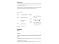
Description
The GL-235 is a differential temperature control for solar heating of pools, spas, and hot tubs. It provides
differential temperature control with an adjustable, calibrated water temperature high limit. Automatic
nocturnal cooling (for pools that overheat in hot climates) and recirculate freeze protection functions can
be enabled/disabled via internal jumpers.
Input power can be either 115 or 240 VAC. The output controls a 24VAC automatic valve actuator. For
older systems with 12VAC valves, an internal jumper can be moved to select 12VAC output operation. The
GL-235 also has a high voltage output for controlling a filter pump or booster pump.
Specifications
Power:
Output:
Desired
Pool
Temp.:
105-130VAC, .5A 50/60Hz.
or
195-250VAC, .3A 50/60Hz
Selectable low voltage 24VAC,
20VA, .85A or 12VAC, 20VA,
1.7A
Recirculate
freeze:
SPST-NO isolated contact
115VAC 1HP
240VAC 2HP
Sensors:
Differential:
Nocturnal
cooling:
2 required (thermistor,
10Kohm @ 25C/77ºF).
70-104ºF calibrated scale or Solar Off, 75 (24ºC) -104ºF (40ºC)
on some models
On at <40ºF (4.5ºC), off at > 42ºF
(5.5ºC), Enabled via jumper
On when collector 8ºF less than
pool and pool hotter than limit,
off when collector 3ºF less than
pool or pool cooler than high limit.
Enabled via jumper
on at 4ºF, off at 1.5ºF
Installation
Mounting
The GL-235 is designed for outdoor use. Mount the box vertically with the knockouts facing downward.
For safety, the GL-235 must be a minimum of 5 feet (horizontally) from the pool or spa.
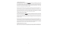
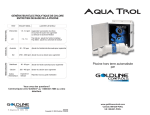
Power input
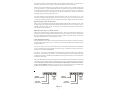
Turn off power at circuit breaker before wiring. Remove the internal panel to expose the wiring connections.
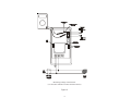
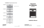
Either 115VAC or 240VAC can be used. Refer to the input wiring diagram (Figure 1) on next page.
WARNING: Applying 240VAC to the 120VAC input terminals will cause permanent damage to the
control.
Grounding
Refer to NEC and local codes for specific grounding requirements. In general, a separate ground conductor
must be run to the ground terminal on the pool service panel.
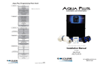
Low Voltage (LV) output: Solar Valve
The GL-235 controls a single valve. In most applications this is the solar valve, which diverts water through
the collector panels or through the normal pool loop depending on conditions.
2
All controls are shipped with the output voltage set to the industry standard 24VAC. To use the GL-235
with older 12VAC valves, move jumper J4, located on the right side of the circuit board.
The GL-235 provides two different types of connections to the pool/spa actuators. For older actuators with
no wire end connector, a 3 position terminal block is used. Connect the wires to the proper terminal block
according to the color code shown in Figure 4. If the valve operates opposite to the way it is supposed to,
reverse the red and white wires. Be careful not to short the valve output wiring. The GL-235 is fused and
shorting the output will require replacing the fuse.
For newer Goldline, Compool, Hayward, and Jandy actuators (with wire end connectors), two 3-pin
connectors are supplied. Plug the actuator into one of the two 3 pin connectors as shown in figures 2 or
3. If the valve operates opposite to the way it is supposed to, disconnect and plug into the other connector.
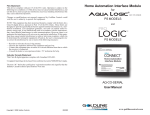
High Voltage (HV) output: Booster Pump
The GL-235 can control a high voltage booster pump in addition to the normal low voltage solar valve. Note
the high voltage relay contacts are isolated so that the booster pump can be run on a separate circuit, as
required by many local codes. The GL-235 turns on, the valve output will operate first, and then the HV
relay will operate 30 seconds later.
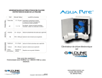
High Voltage (HV) output: Timeclock Override
The GL-235 can also be used to override the filter pump timer. This is very important if recirculate freeze
protection or nocturnal cooling functions are being used. Also, this function can be used on systems where
the system should operate whenever solar heat is available, regardless of the timer settings. The HV relay
will operate approximately 30 seconds after the LV relay.
Sensor Mounting and Wiring
Most installations use a PC sensor to measure the pool temperature and another PC sensor to measure the
solar temperature. Alternatively, an SC-¼ sensor can be screwed into the pump strainer basket to measure
the pool temperature.
Pool Sensor: Drill a 3/8” (or 5/16”) hole in the PVC pipe. Remove burrs around the hole. Check that the
O-ring is seated on the PC sensor and then insert sensor into pipe. Tighten hose clamp over the sensor to
make a seal—DO NOT OVERTIGHTEN.
Solar Sensor: Use a screw or silicon adhesive to attach the sensor near the solar collector array. The sensor
does not have to be attached to the collectors. It is only important that the sensor be exposed to the same
sunlight as the collectors. Additionally, the underside of the sensing element may be covered with silicon
to minimize wind cooling.
EARTH
GROUND
high
voltage
output
240 VAC
input power
115 VAC
input power
Figure 1
3
{
EARTH
GROUND
{
Other 10K ohm Goldline sensors may be substituted. Wire should be twisted pair 20AWG. Sensor wiring
run outdoors must be rated for outdoor use and ensure that the wire connections are protected from the
weather. Do NOT run sensor wires in the same conduit or multiconductor cable as the valve actuator wires or any 120/240V circuit. For long runs or runs near other electrical wiring use shielded cable
(Belden 8428 for outdoor use). Ground the shields to the GL-35/LV ground screw.
high
voltage
output
Freeze Protection
If you are relying on the collectors naturally draining to provide freeze protection, it is very important that
you use a non-positive seal valve or drill a hole (1/8"--1/4") in the diverter of a positive seal valve to
allow the collectors to drain. Alternatively, the GL-235 control can provide recirculate freeze protection.
If enabled, when the GL-235 senses a freeze condition at the collector sensor, it will allow circulation of
relatively warm water from the pool to the collector panels.
The GL-235 will allow recirculation when the collector temperature falls below 40ºF and will stop
circulation when the collector temperature rises above 42ºF. While this type of freeze protection has proven
to be adequate in relatively mild climates, it is extremely important that the sensors be properly placed and
that the homeowner realize that the system is unprotected in the event of a power failure. Recirculate freeze
protection is NOT recommended in climates where freezing temperatures are common or last for extended
periods.
Goldline strongly recommends the use of GC-3 freeze snap switches if freeze protection is being utilized.
Snap switches should be wired in series with the collector sensor. Placement of the snap switches at the
coldest point of the collector array and exposed plumbing will help assure that freeze protection starts early
enough to protect the system.
The GL-235 is shipped from the factory with recirculate freeze protection disabled (the jumper is present
but installed on one pin only). To activate recirculate freeze protection, install the jumper across both pins
marked “RECIRC”, located near the top right of the main circuit board.
If recirculate freeze protection is to be used on a GL-235, either:
•
The filter pump must be set for continuous operation
or
• The GL235 High Voltage Output must be wired for Timer Override function.
Nocturnal Cooling
The GL-235 has nocturnal cooling logic, which can be enabled/disabled via a jumper on the main circuit
board. During nighttime hours, when enabled, the GL-235 will circulate relatively warmer water from the
pool to the collector panels, thus cooling the pool over time. The GL-235 will circulate water when the
collector temperature AND the pool temperature is hotter than the high limit setting. Circulation will stop
when the collector temperature is 3ºF less than the pool temperature OR the pool temperature is cooler than
the high limit setting. The GL-235 is shipped from the factory with nocturnal cooling disabled (the jumper
is present but installed on one pin only). To activate nocturnal cooling, install the jumper provided onto the
two pins marked “COOLING” located near the top right of the main circuit board.
If nocturnal cooling is to be used, either:
• The filter pump must be set for continuous operation
• The GL-235 High Voltage Output must be wired for Timer Override function.
4
or
Operation
For normal operation place the switch in the “AUTO” position and adjust the desired pool/spa temperature
setting. The “Power” LED indicator should always be on. (NOTE: During initial power up, the “POWER
indicator will blink for approximately 10 seconds while it stabilizes temperature readings). The “Heating”
LED indicator will show when the system is collecting solar heat. If the nocturnal cooling function is
enabled inside the GL-235, the “Cooling” LED indicator will show when the system is dissipating excess
heat.
In the “AUTO” position, the GL-235 will heat the pool or spa (rotate valve to solar loop) when the collector
(solar) sensor temperature is higher than the pool/spa sensor temperature by 4ºF or more AND the pool/spa
temperature is less than the "Desired Temperature" setting. The GL-235 will stop heating (return valve to
pool loop) when the two sensor temperatures get to within 1.5ºF OR the pool/spa sensor is above the
"Desired Temperature" setting.
To test the system, move the switch to “MANUAL TEST” and verify that both the “Heating” and “Cooling”
indicators light and that the valve(s) are in the solar loop position. Move the switch to “MANUAL OFF”
and verify that all indicators except “Power” are off. The valve(s) should be in the normal recirculating loop
position. If the valve(s) positions are working in reverse, follow the instructions in section marked “Low
Voltage (LV) : Solar Valve” to correct. WARNING: If recirculate freeze protection is being used, do
NOT leave the switch in the “MANUAL OFF” position during cold weather. Also note that the switch
does NOT turn power off to the GL-235.
Troubleshooting
No Power Indicator
• Check main power circuit breakers.
• Check fuse
Fuse Replacement
The GL-235 is protected by a fuse located on the left side of the main circuit board. Replace the fuse with
a 2A, type ATO-2 fuse, readily available in most automotive or electronics stores.
If “Heating” is always on
Disable recirculate freeze protection if enabled. Check that the switch is in the “AUTO” position. Next
verify that the control circuitry is operating properly by disconnecting the solar sensor from the terminal
block. The “Heating” LED should go off and the “CHECK SENSOR” LED should begin to blink. If
“Heating” remains on, there is an internal circuit failure and the GL-235 will have to be returned for repair.
If “Heating” never comes on
Verify that the switch is in the “AUTO” position, the desired pool temperature dial is set higher (hotter) that
the actual pool temperature, and the solar sensor is warmer than the pool water. Also check that the switch
on the valve actuator is NOT in the "OFF" position. Disconnect the pool sensor from the terminal block and
verify that the “CHECK SENSOR” LED turns on. If the “CHECK SENSOR” LED does not turn on, there
is an internal failure and the GL-235 will have to be returned for repair. Reconnect the pool sensor and verify
that the “Check Sensor” LED turns off. Next, disconnect the “solar” sensor from the terminal block and
verify that the “CHECK SENSOR” LED begins to blink. If the “CHECK SENSOR” LED does not begin
to blink, there is an internal failure and the GL-235 will have to be returned for repair.
5
“CHECK SENSOR” indicator on
If the “CHECK SENSOR indicator is on and NOT blinking, there may be a possible open circuit or short
circuit with the pool sensor. Using a voltmeter, measure the DC voltage across the terminals of the pool
sensor as indicated in figure 5. If the voltage is close to zero volts, the sensor has a short to ground. Remove
the sensor from the terminal block and measure the voltage across the pool terminals again. If the voltage
is still close to zero volts, there is an internal short and the unit must be returned for repair. If the voltage
is close to five volts, the pool sensor itself may be at fault.
With the sensor disconnected from the unit, measure the resistance of the sensor using an ohmmeter. At
room temperature (25ºC/77ºF) the sensor should measure approximately 10K ohms (10,000 ohms ± 1%).
For other resistance measurements at different temperatures, consult the table at back of manual. If the
sensor is not returning the correct value, it is defective and will need to be replaced. If the sensor is returning
approximately the correct value, reconnect it to the terminals marked “POOL SENSOR”. If the “CHECK
SENSOR” indicator remains on, the unit is defective and needs to be replaced.
“CHECK SENSOR” indicator blinking
If the “CHECK SENSOR indicator is blinking, there may be a possible open circuit or short circuit with the
solar sensor. Using a voltmeter, measure the voltage across the terminals of the solar sensor. If the voltage
is close to zero volts, the sensor has a short to ground. Remove the sensor from the terminal block and
measure the voltage across the solar terminals again. If the voltage is still close to zero volts, there is an
internal short and the unit must be returned for repair. If the voltage is close to five volts, the solar sensor
itself may be at fault.
With the sensor disconnected from the unit, measure the resistance of the sensor using an ohmmeter. At
room temperature (25ºC/77ºF) the sensor should measure approximately 10K ohms (10,000 ohms ± 1%).
For other resistance measurements at different temperatures, consult the table at back of manual. If the
sensor is not returning the correct value, it is defective and will need to be replaced. If the sensor is returning
approximately the correct value, reconnect it to the terminals marked “SOLAR SENSOR”. If the “CHECK
SENSOR” indicator remains on, the unit is defective and needs to be replaced.
If FREEZE PROTECTION is enabled:
When a sensor is disconnected from the unit and freeze protection has been enabled, the SENSOR FAULT
light will NOT activate. The GL-235 will recognize this as a freeze condition and activate freeze protection.
6
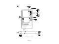
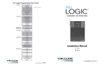
Basic Installation of GL-235
Figure 2
7
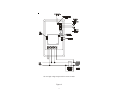
GL-235 high voltage output used for Timer Override
Figure 3
8
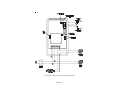
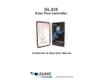
GL-235 high voltage output used for Booster Pump
Figure 4
9
Measuring Voltage of Pool Sensor
(Use the same method to measure the Solar Sensor)
Figure 5
10
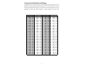
Temperature/Resistance/Voltage
All Goldline controls use 10K thermistor sensors. When disconnected from the control the sensor will read
10K ohms at 25ºC/77ºF. Refer to the chart below for the resistance at other temperatures. For a given
temperature, the resistance reading should be accurate to ±1%. For a given resistance reading, the
temperature reading should be accurate to ±0.5ºF. Voltage measurements should be accurate to ± 2%. Ohm
measurements made with sensor disconnected from unit. Voltage measurements made with sensor
connected to unit and power applied.
Sensor voltages are DC volts.
°F
1
2
3
4
5
6
7
8
9
10
11
12
13
14
15
16
17
18
19
20
21
22
23
24
25
26
27
28
29
30
31
32
33
34
35
36
37
38
39
40
Ohms
82,719
80,142
77,656
75,255
72,937
70,698
68,535
66,447
64,428
62,479
60,595
58,774
57,014
55,313
53,669
52,078
50,541
49,054
47,616
46,225
44,879
43,577
42,318
41,099
39,919
38,777
37,671
36,601
35,565
34,561
33,590
32,648
31,737
30,853
29,998
29,169
28,365
27,587
26,832
26,100
Volts
4.46
4.45
4.43
4.41
4.40
4.38
4.36
4.35
4.33
4.31
4.29
4.27
4.25
4.23
4.21
4.19
4.17
4.15
4.13
4.11
4.09
4.07
4.04
4.02
4.00
3.97
3.95
3.93
3.90
3.88
3.85
3.83
3.80
3.78
3.75
3.72
3.70
3.67
3.64
3.61
°F
41
42
43
44
45
46
47
48
49
50
51
52
53
54
55
56
57
58
59
60
61
62
63
64
65
66
67
68
69
70
71
72
73
74
75
76
77
78
79
80
Ohms
25,391
24,704
24,037
23,391
22,764
22,156
21,566
20,993
20,438
19,900
19,377
18,870
18,377
17,899
17,435
16,985
16,548
16,123
15,711
15,310
14,921
14,543
14,176
13,820
13,473
13,136
12,809
12,491
12,182
11,882
11,589
11,305
11,029
10,761
10,500
10,246
9,999
9,758
9,525
9,297
Volts
3.59
3.56
3.53
3.50
3.47
3.45
3.42
3.39
3.36
3.33
3.30
3.27
3.24
3.21
3.18
3.15
3.12
3.09
3.06
3.02
2.99
2.96
2.93
2.90
2.87
2.84
2.81
2.78
2.75
2.72
2.68
2.65
2.62
2.59
2.56
2.53
2.50
2.47
2.44
2.41
°F
81
82
83
84
85
86
87
88
89
90
91
92
93
94
95
96
97
98
99
100
101
102
103
104
105
106
107
108
109
110
111
112
113
114
115
116
117
118
119
120
11
Ohms
9,076
8,861
8,651
8,447
8,249
8,056
7,867
7,684
7,506
7,333
7,164
6,999
6,839
6,683
6,530
6,382
6,238
6,097
5,960
5,827
5,697
5,570
5,446
5,326
5,208
5,094
4,982
4,873
4,767
4,664
4,563
4,464
4,368
4,274
4,183
4,094
4,007
3,922
3,839
3,758
Volts
2.38
2.35
2.32
2.29
2.26
2.23
2.20
2.17
2.14
2.12
2.09
2.06
2.03
2.00
1.98
1.95
1.92
1.89
1.87
1.84
1.81
1.79
1.76
1.74
1.71
1.69
1.66
1.64
1.61
1.59
1.57
1.54
1.52
1.50
1.47
1.45
1.43
1.41
1.39
1.37
°F
121
122
123
124
125
126
127
128
129
130
131
132
133
134
135
136
137
138
139
140
141
142
143
144
145
146
147
148
149
150
151
152
153
154
155
156
157
158
159
160
Ohms
3,679
3,602
3,527
3,454
3,382
3,312
3,244
3,177
3,112
3,049
2,987
2,926
2,867
2,809
2,752
2,697
2,643
2,591
2,539
2,489
2,440
2,392
2,345
2,299
2,254
2,210
2,167
2,125
2,084
2,044
2,005
1,966
1,929
1,892
1,856
1,821
1,787
1,753
1,720
1,688
Volts
1.34
1.32
1.30
1.28
1.26
1.24
1.22
1.21
1.19
1.17
1.15
1.13
1.11
1.10
1.08
1.06
1.05
1.03
1.01
1.00
0.98
0.97
0.95
0.93
0.92
0.90
0.89
0.88
0.86
0.85
0.84
0.82
0.81
0.80
0.78
0.77
0.76
0.75
0.73
0.72
LIMITED WARRANTY Goldline warrants its Aqua Rite, Aqua Rite Pro, Aqua Trol, Aqua
Logic and Pro Logic products (products with Goldline part numbers starting with AQ-RITE-,
AQ-RT-PRO, AQ-TROL-, AQ-LOGIC-, AQL-P-, AQL-PS-, AQL-CL-, PL-P-, PL-PS-, and
HPC-2) to be free from defects in material or workmanship, under normal use and service:
For three years from the date of the initial system installation on private, residential swimming
pools within the USA or Canada and one year from the date of initial system installation on
commercial installations, installations outside of the USA or Canada and for any replacement
parts or accessory products, provided they are installed in accordance with the Goldline
installation instructions and specifications provided with the product. If written proof of the date
of the initial system installation is not provided to Goldline, the manufacturing datecode on the
Aqua Rite, Aqua Rite Pro, Aqua Trol, Aqua Logic and Pro Logic electronics unit will be the sole
determinant of the date of the initial system installation.
For residential installations in USA or Canada: If a product is defective in workmanship or
materials and is removed and returned freight prepaid within three (3) years after the date of the
initial system installation, Goldline will, at its option, either repair or replace the defective product
and return it freight prepaid.
For commercial installations, installations outside the USA and Canada, and accessory products
and replacement parts: If a product is defective in workmanship or materials and is removed and
returned freight prepaid within one (1) year after the date of the initial system installation,
Goldline will, at its option, either repair or replace the defective product and return it freight
prepaid.
Contact any Goldline dealer or contact Goldline at 61 Whitecap Drive, North Kingstown, RI
02852 for warranty service. The costs incurred in removal and/or reinstallation of the product are
NOT covered under this warranty. Some states do not allow limitations on how long an implied
warranty lasts, so the above limitation may not apply to you.
WARRANTY EXCLUSIONS:
1.
Material supplied or workmanship performed by others in process of installation.
2.
Damage resulting from improper installation including installation on pools larger than the
product rating.
3.
Problems resulting from failure to operate the product(s) in accordance with the recommended instructions contained in product’s owners manual(s).
4.
Problems resulting from failure to maintain pool water chemistry in accordance with the
recommendations in the owners manual(s).
5.
Problems resulting from tampering, accident, abuse, negligence, unauthorized repairs or
alternations, fire, flood, lightning, freezing, external water, degradation of natural stone
used in or immediately adjacent to a pool or spa, war or acts of God.
DISCLAIMER. THE EXPRESS LIMITED WARRANTY ABOVE CONSTITUTES THE
ENTIRE WARRANTY OF GOLDLINE WITH RESPECT TO ITS POOL AUTOMATION AND CHLORINATION PRODUCTS AND IS IN LIEU OF ALL OTHER WARRANTIES, EXPRESSED OR IMPLIED, INCLUDING WARRANTIES OF MERCHANTABILITY OR FITNESS FOR A PARTICULAR PURPOSE. THIS WARRANTY GIVES
YOU SPECIFIC LEGAL RIGHTS, AND YOU MAY ALSO HAVE OTHER RIGHTS
WHICH VARY FROM STATE TO STATE. IN NO EVENT SHALL GOLDLINE BE
RESPONSIBLE FOR ANY CONSEQUENTIAL, SPECIAL OR INCIDENTAL DAMAGES OF ANY NATURE WHATSOEVER, INCLUDING, BUT NOT LIMITED TO,
PERSONAL INJURY, PROPERTY DAMAGE, DAMAGE TO OR LOSS OF EQUIPMENT, LOST PROFITS OR REVENUE, COSTS OF RENTING REPLACEMENTS,
AND OTHER ADDITIONAL EXPENSES, EVEN IF THE SELLER HAD BEEN ADVISED OF THE POSSIBILITY OF SUCH DAMAGES. SOME STATES DO NOT
ALLOW THE EXCLUSION OF LIMITATION OF INCIDENTAL OR CONSEQUENTIAL DAMAGES, SO THE ABOVE LIMITATION OR EXCLUSION MAY NOT
APPLY TO YOU.
NO WHOLESALER, AGENT, DEALER, CONTRACTOR OR OTHER PERSON IS
AUTHORIZED TO GIVE ANY WARRANTY ON BEHALF OF GOLDLINE.
THIS WARRANTY IS VOID IF THE PRODUCT HAS BEEN ALTERED IN ANY WAY
AFTER LEAVING THE FACTORY.
N. Kingstown, RI 02852 USA
092007G
Copyright © 2008 Goldine Controls