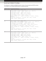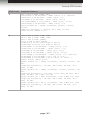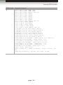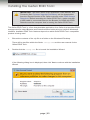
1
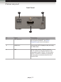
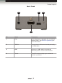
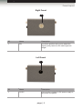
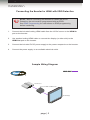
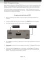
3GSDI
Audio
Embedder
Booster for HDMI
with EDID Detective
EXT-HDBOOST-141
User Manual
Release A4
Booster for HDMI with EDID Detective
Important Safety Instructions
GENERAL SAFETY INFORMATION
1.
Read these instructions.
2.
Keep these instructions.
3.
Heed all warnings.
4.
Follow all instructions.
5.
Do not use this product near water.
6.
Clean only with a dry cloth.
7.
Do not block any ventilation openings. Install in accordance with the manufacturer’s
instructions.
8.
Do not install or place this product near any heat sources such as radiators, heat
registers, stoves, or other apparatus (including amplifiers) that produce heat.
9.
Do not defeat the safety purpose of the polarized or grounding-type plug. A polarized
plug has two blades with one wider than the other. A grounding type plug has two
blades and a third grounding prong. The wide blade or the third prong are provided for
your safety. If the provided plug does not fit into your outlet, consult an electrician for
replacement of the obsolete outlet.
10. Protect the power cord from being walked on or pinched particularly at plugs,
convenience receptacles, and the point where they exit from the apparatus.
11. Only use attachments/accessories specified by the manufacturer.
12. To reduce the risk of electric shock and/or damage to this product, never handle or
touch this unit or power cord if your hands are wet or damp. Do not expose this
product to rain or moisture.
13. Unplug this apparatus during lightning storms or when unused for long periods of time.
14. Refer all servicing to qualified service personnel. Servicing is required when the
apparatus has been damaged in any way, such as power-supply cord or plug is
damaged, liquid has been spilled or objects have fallen into the apparatus,
the apparatus has been exposed to rain or moisture, does not operate normally,
or has been dropped.
15. Batteries that may be included with this product and/or accessories should never be
exposed to open flame or excessive heat. Always dispose of used batteries
according to the instructions.
ii
Booster for HDMI with EDID Detective
Warranty Information
Gefen warrants the equipment it manufactures to be free from defects in material and
workmanship.
If equipment fails because of such defects and Gefen is notified within two (2) years from
the date of shipment, Gefen will, at its option, repair or replace the equipment, provided
that the equipment has not been subjected to mechanical, electrical, or other abuse or
modifications. Equipment that fails under conditions other than those covered will be
repaired at the current price of parts and labor in effect at the time of repair. Such repairs
are warranted for ninety (90) days from the day of reshipment to the Buyer.
This warranty is in lieu of all other warranties expressed or implied, including without
limitation, any implied warranty or merchantability or fitness for any particular purpose, all of
which are expressly disclaimed.
1.
Proof of sale may be required in order to claim warranty.
2.
Customers outside the US are responsible for shipping charges to and from Gefen.
3.
Copper cables are limited to a 30 day warranty and cables must be in their original
condition.
The information in this manual has been carefully checked and is believed to be accurate.
However, Gefen assumes no responsibility for any inaccuracies that may be contained
in this manual. In no event will Gefen be liable for direct, indirect, special, incidental, or
consequential damages resulting from any defect or omission in this manual, even if
advised of the possibility of such damages. The technical information contained herein
regarding the features and specifications is subject to change without notice.
For the latest warranty coverage information, refer to the Warranty and Return Policy under
the Support section of the Gefen Web site at www.gefen.com.
PRODUCT REGISTRATION
Please register your product online by visiting the Register Product page under the
Support section of the Gefen Web site.
iii
Booster for HDMI with EDID Detective
Contacting Gefen Technical Support
Gefen, LLC
c/o Customer Service
20600 Nordhoff St.
Chatsworth, CA 91311
Telephone:
(818) 772-9100
(800) 545-6900
Fax:
(818) 772-9120
Email:
[email protected]
Visit us on the Web:
www.gefen.com
Technical Support Hours:
8:00 AM to 5:00 PM Monday - Friday, Pacific Time
Booster for HDMI with EDID Detective
is a trademark of Gefen, LLC.
Important Notice
Gefen, LLC reserves the right to make changes in the hardware, packaging, and any
accompanying documentation without prior written notice.
HDMI, the HDMI logo, and High-Definition Multimedia Interface are trademarks or
registered trademarks of HDMI Licensing in the United States and other countries.
© 2013 Gefen, LLC. All Rights Reserved.
All trademarks are the property of their respective owners.
iv
3GSDI Audio
Booster
for HDMI
Embedder
with EDID Detective
Operating Notes
•
The Gefen Booster for HDMI with EDID Detective extends HDMI up to 150 feet
(45 meters) at 1080p Full HD and up to 115 feet (35 meters) at 4K x 2K Ultra HD
resolution, using standard copper HDMI cables to keep sources and displays in sync.
•
The Gefen Booster for HDMI with EDID Detective comes pre-programmed with 6
default EDID profiles as well as 6 user-programmable EDID banks.
•
To access all features and select the Default EDID profiles, refer to Installing the
Gefen EDID Tool+.
v
Booster for HDMI with EDID Detective
Features and Packing List
Features
•
Extends copper HDMI cables up to 150 feet (45 meters) at 1080p Full HD, and up to
115 feet (35 meters) at 4K x 2K Ultra HD
•
Supports resolutions up to Ultra HD 4K x 2K (3840 x 2160 @ 30Hz), 1080p Full HD,
and 2048 x 1536 (QXGA)
•
HDMI Features Supported:
►► HDCP
►► 12-bit Deep Color
►► LPCM 7.1 audio, Dolby® TrueHD, and DTS-HD Master Audio™
►► 3DTV pass-through
►► Lip-Sync pass-through
►► CEC pass-through
•
USB port for advanced programming of features such as video equalization,
pre-emphasis, and EDID management
•
DDC Re-clocking
•
EQ adjustment for best results with varying cable types and lengths
•
Can record the EDID from a display
•
6 pre-programmed EDID profiles
•
6 user-programmable EDID banks for copying/uploading EDIDs
•
Selectable HDCP pass-through
•
Field-upgradable firmware via USB port
•
Compact and portable
®
1080P
Packing List
The Booster for HDMI with EDID Detective ships with the items listed below. If any of these
items are not present in your box when you first open it, immediately contact your dealer or
Gefen.
•
•
•
•
•
1 x Booster for HDMI with EDID Detective
1 x 1 ft. locking HDMI cable
1 x 6ft. USB Mini USB to USB
1 x 5V DC power supply
1 x Quick-Start Guide
vi
3GSDI Audio
Booster
for HDMI
Embedder
with EDID Detective
Table of Contents
01
Getting Started
Panel Layout.......................................................................................................... 2
Front Panel..................................................................................................... 2
Back Panel..................................................................................................... 3
Right Panel..................................................................................................... 4
Left Panel....................................................................................................... 4
Installation.............................................................................................................. 5
Connecting the Booster for HDMI with EDID Detective�������������������������������� 5
Sample Wiring Diagram................................................................................. 5
02
Operating the Booster for HDMI
with EDID Detective
EDID Programming................................................................................................ 8
Programming an External EDID..................................................................... 8
Loading an EDID from a Bank..................................................................... 10
Storing an EDID to a Bank........................................................................... 11
HDCP Control.............................................................................................. 12
Adjusting the Video Signal................................................................................... 13
Using the EQ Switch.................................................................................... 13
Using Commands......................................................................................... 13
03
Advanced Operation
Using the Virtual COM Port.................................................................................. 16
Installing the Driver...................................................................................... 16
Commands........................................................................................................... 20
04Appendix
Default EDID Profiles........................................................................................... 42
Installing the Gefen EDID Tool+........................................................................... 45
Installing the Gefen EDID Tool+.................................................................. 45
Firmware Upgrade Procedure.............................................................................. 48
Specifications....................................................................................................... 49
viii
Booster for HDMI
with EDID Detective
01 Getting Started
Panel Layout.......................................................................................................... 2
Front Panel..................................................................................................... 2
Back Panel..................................................................................................... 3
Right Panel..................................................................................................... 4
Left Panel....................................................................................................... 4
Installation.............................................................................................................. 5
Connecting the Booster for HDMI with EDID Detective�������������������������������� 5
Sample Wiring Diagram................................................................................. 5
Getting Started
Panel Layout
Front Panel
1
3
2
ID
Name
Description
1
DIP switches
Use this DIP switch bank to select a
pre-programmed EDID. See EDID
Programming for more information.
2
HDMI Out
Connect the HDTV display to this port using
an HDMI cable.
3
WR
Write-enable switch. Flip this switch to
the “E” position to allow the booster to be
programmed with an EDID. Set this switch
to the “D” position to disable programming
and prevent an accidental erasure of the
current EDID.
page | 2
Getting Started
Panel Layout
Back Panel
1
3
4
2
ID
Name
Description
1
Prog
Press this button to program the unit with the
desired EDID. See EDID Programming for
more information.
2
HDMI In
Connect the Hi-Def source to this port using
an HDMI cable.
3
USB
Connect a USB cable to provide an
alternate power source for the booster.
4
Power
This LED will glow bright green when the
booster is powered.
page | 3
Getting Started
Panel Layout
Right Panel
1
ID
Name
Description
1
EQ
Use this 8-position rotary pot to adjust the
signal quality, based on the cable type and
length.
Left Panel
1
ID
Name
Description
1
5V DC
Connect the included 5V DC power supply to
this power receptacle.
page | 4
Getting Started
Installation
Page Title
Connecting the Booster for HDMI with EDID Detective
STOP: Before connecting the Booster for HDMI with EDID
Detective, the unit must be programmed with an EDID.
See EDID Programming for instructions on EDID programming
before continuing.
1.
Connect the included locking HDMI cable from the Hi-Def source to the HDMI In
port on the booster.
2.
Use another locking HDMI cable to connect the display (or other sink) to the
HDMI Out port on the booster.
3.
Connect the included 5V DC power supply to the power receptacle on the booster.
4.
Connect the power supply to an available electrical outlet.
Sample Wiring Diagram
HDMI CABLE
Ultra HD Source
Booster for HDMI w/ EDID Detective
Ultra HD Display
EXT-HDBOOST-141
page | 5
Booster for HDMI
with EDID Detective
02 Operating the Booster for HDMI
with EDID Detective
EDID Programming................................................................................................ 8
Programming an External EDID..................................................................... 8
Loading an EDID from a Bank..................................................................... 10
Storing an EDID to a Bank........................................................................... 11
HDCP Control.............................................................................................. 12
Adjusting the Video Signal................................................................................... 13
Using the EQ Switch.................................................................................... 13
Using Commands......................................................................................... 13
Operating the Booster for HDMI with EDID Detective
EDID Programming
Before using the Booster for HDMI with EDID Detective, the unit must be programmed with
an EDID. Once programmed, the EDID data will be read by the source, providing all the
necessary details of the type of signal that the display (or other sink device) can process.
There are two ways in which to program the booster: 1) The EDID data can come from
an external source, such as a display or A/V receiver. 2) The booster can be programmed
using any of the 6 Default EDID profiles .
Programming an External EDID
1.
Begin by powering-on the display or other sink device containing the EDID to be
recorded.
2.
Connect an HDMI cable from the sink device to the HDMI Out port on the booster.
3.
Set all DIP switches to the OFF (up) position, as shown below.
DIP switches
in OFF position
Slide switch to
the E position
4.
Set the WR (write) switch to the E position in order to allow the EDID to be written to
the booster.
5.
Connect the included 5V DC power supply to the booster. The Power LED will glow
bright green.
6.
Press and hold the Program button on the booster, until the Power LED begins to
flash rapidly. The Power LED will continue to flash as the EDID is recorded by the
booster. This process only takes about 1 second.
page | 8
Operating the Booster for HDMI with EDID Detective
Page Title
EDID Programming
Press the
Prog button
If the EDID was recorded successfully, then the Power LED will glow solid green.
If an error was encountered during the recording process, then the Power LED will
flash bright red.
If an error is encountered, disconnect the 5V DC power supply from the booster,
power-cycle the display, then repeat steps 5 and 6. If an error is encountered after
several attempts, then this may indicate that the sink device has a bad EDID.
LED
Power
7.
Status
Condition(s)
Solid green
•
•
Booster is powered.
EDID recorded successfully.
Flashing
red
•
•
•
Bad / corrupt EDID at sink.
No sink device detected.
Write-protected booster (WR = D).
Flashing
green
•
EDID is being recorded.
Set the WR (write) switch to the D position in order to prevent the stored EDID from
being accidentally erased or overwritten.
If the WR (write) switch is in the D position while attempting to record an EDID, the
Power LED will flash red, once.
8.
The Booster for HDMI with EDID Detective can now be used to connect two cables,
between the source and the sink. See Connecting the Booster for HDMI with EDID
Detective for details.
page | 9
Operating the Booster for HDMI with EDID Detective
EDID Programming
Loading an EDID from a Bank
NOTE: The Booster for HDMI with EDID Detective ships with 6
Default EDID Profiles. See Default EDID Profiles for each internal
pre-programmed EDID profile.
1.
Connect the included 5V DC power supply to the booster.
2.
Set the WR (write) switch to the E position in order to allow the EDID to be written to
the booster.
3.
Select the desired EDID bank, using the piano DIP switches. Refer to the chart,
below. DIP switch 4 is not used when selecting an EDID bank.
Bank
DIP SW 1
DIP SW 2
DIP SW 3
DIP SW 4
1
ON
OFF
OFF
Not used
2
OFF
ON
OFF
3
ON
ON
OFF
4
OFF
OFF
ON
5
ON
OFF
ON
6
OFF
ON
ON
For example, if we wanted to recall the EDID that is stored in EDID bank 4, then we
would set the DIP switches to SW1 = OFF, SW2 = OFF, SW3 = ON.
4.
Press and hold the Program button on the booster. The Power LED will flash as the
EDID is recalled from the specified bank and loaded to the local input (HDMI In) on the
booster.
5.
Set the WR (write) switch to the D position in order to prevent the stored EDID from
being accidentally erased or overwritten.
Recalling an EDID from a bank (to the Local EDID) can also be accomplished by
using the #edidbatolo command.
page | 10
Operating the Booster for HDMI with EDID Detective
EDID Programming
Storing an EDID to a Bank
WARNING: When an EDID is stored in an EDID bank, the original
EDID data will be lost. The #saveloedid command can be used
as part of the process to save the EDID data to a file.
The Booster for HDMI with EDID Detective can store EDID data in 6 separate EDID
banks. Once an EDID is stored in a bank, it can be recalled for later use. Each EDID
bank can store up to 256 bytes of EDID data. In order to store an EDID to a bank, use the
#ediddstoba command. See Using the Virtual COM Port for more information on using
commands.
1.
Begin by powering-on the display or other sink device containing the EDID
to be recorded.
2.
Connect the included 5V DC power supply to the booster.
3.
Set all DIP swtiches to the OFF (up) position, as shown below.
DIP switches
in OFF position
4.
Connect an HDMI cable from the sink device to the HDMI Out port on the booster.
The Power LED will glow bright green if the sink device contains a valid EDID. If the
EDID is corrupt or invalid, then the Power LED will flash bright red.
5.
Use the #ediddstoba command to record the downstream EDID to the desired
bank. For example, to record the downstream EDID to bank 2, we would use the
following command syntax:
#ediddstoba 2
6.
To fill the remaining 5 EDID banks with EDID data, repeat steps 4 and 5, following the
#ediddstoba command with a different bank number. If an EDID is stored in a bank
with existing EDID data, then the existing EDID data will be overwritten.
page | 11
Operating the Booster for HDMI with EDID Detective
EDID Programming
HDCP Control
In order for the Booster for HDMI with EDID Detective to pass HDCP content (e.g. Blu-ray,
etc.), DIP switch 4 must be set to the OFF (up) position. This is the factory-default setting.
In some cases, computers will enable HDCP if an HDCP-compliant display is detected.
To force the computer to ignore detection of an HDCP-compliant display, set DIP switch 4
to the ON (down) position.
HDCP can also be controlled using the #ddcmode command.
page | 12
Operating the Booster for HDMI with EDID Detective
Adjusting the Video Signal
Using the EQ Switch
Due to the high data rates supported by the booster over long cables, video artifacts
and/or drop-outs may occur. The rotary EQ switch can boost signal gain from 0 dB to 27
dB. Use a small flathead screwdriver to rotate the EQ switch to one of the 8 positions.
Use a small flathead
screwdriver to adjust
the EQ switch
Switch Position
Signal gain
Switch Position
Signal gain
0
0 dB
4
23 dB
1
10 dB
5
25 dB
2
16 dB
6
26 dB
3
19 dB
7
27 dB
The following table provides general guidelines for cable length, gauge (AWG),
and timing information:
Length
Gauge (AWG)
Timing
115 feet (35 meters)
24
4K x 2K
148 feet (45 meters)
24
1080p / 60 Hz
180 feet (55 meters)
24
720p / 60 Hz
Since each situation is unique, different lengths and gauges may produce different
timings.
Using Commands
In addition to adjusting the EQ setting using the rotary switch, the #eq command can also
be used. The command set also provides control of additional features. See Commands
for information on each command.
page | 13
Booster for HDMI
with EDID Detective
03 Advanced Operation
Using the Virtual COM Port.................................................................................. 16
Installing the Driver...................................................................................... 16
Commands........................................................................................................... 20
Advanced Operation
Using the Virtual COM Port
Installing the Driver
When the Booster for HDMI with EDID Detective is connected to a computer running the
Windows® operating system, a virtual communications port is created. This feature allows
the internal command set to be used to control the booster. Macintosh computers are also
supported. The following set of instructions is for Windows® only.
1.
Download the driver for the Booster for HDMI with EDID Detective from the Gefen
Web site.
2.
Extract the contents of the .zip file to the Windows® Desktop.
3.
Connect the USB-to-Mini USB cable between the detective and the PC.
4.
After connecting the booster, Windows® will indicate that a driver for the device cannot be located.
5.
Go to Control Panel > Device Manager and click Ports. The Booster for HDMI
with EDID Detective device will appear under the Other devices section, as shown
below. An exclamation mark, within a yellow triangle, indicates that the device is not
recognized by Windows®.
6.
Right-click on the HDMI-EDID BOOSTER device and select Update Driver
Software... from the context menu.
(continued on next page)
page | 16
Advanced Operation
Using the Virtual COM Port
7.
Select Browse my computer for driver software on the Update Driver Software
dialog.
8.
On the following dialog, click the Browse... button and select the location of the .inf
file, which was extracted from the .zip file in step 2. Then, click the Next button.
page | 17
Advanced Operation
Using the Virtual COM Port
9.
While attempting to install the driver, the following dialog will be displayed:
10. Select Install this software anyway.
The driver installation may take a couple of minutes.
11. Once the driver has installed, a dialog with the following message will be displayed.
Click the Close button to complete the installation.
page | 18
Advanced Operation
Using the Virtual COM Port
9.
Verify the installation of the driver by going to Control Panel > Device Manager and
clicking Ports. The Booster for HDMI with EDID Detective will be listed, along with
the virtual COM port that should be used when issuing commands to the booster.
Set the terminal program to
use the specified COM port
page | 19
Advanced Operation
Commands
Command
Description
#cdr
De-emphasis control; enable/disable CDR bypass
#ddcmode
Sets the DDC mode
#de
Sets the de-emphasis on the output
#edidbatolo
Copies the specified EDID bank to the local input
#ediddetolo
Set to default EDID on local input
#ediddstoba
Read downstream EDID and stores in EDID Bank
#ediddstolo
Read the downstream EDID and stores in the local input
#eq
Adjusts the equalizer settings
#eqstat
Displays the current equalizer status
#eredidbank
Erases the specified EDID bank
#fadefault
Resets the booster to factory-default settings
#fw_upgrade
Updates the booster firmware
#help
Displays the list of available commands
#loedidtoba
Loads an EDID file to the specified EDID bank
#maskout
Enables / disabled video output
#prbaedid
Displays the EDID in the specified bank
#prdsedid
Displays the downstream EDID
#prloedid
Displays the EDID stored in the local input
#saveloedid
Saves the EDID on the local input to a file
#show_ver_data
Displays the current hardware and firmware version
#vstat
Displays the signal loss on the input
page | 20
Advanced Operation
Commands
#cdr
The #cdr command provides de-emphasis control and disables / enables CDR bypass.
This feature must be enabled before using the #de command.
Syntax
#cdr param1
Parameters
param1
Value[0 ... 1]
Value
Description
0
CDR disable
1
CDR enable
Example
#cdr 1
page | 21
Advanced Operation
Commands
#ddcmode
The #ddcmode command sets the DDC mode. Use this command to enable / disable
HDCP with the local EDID or use EDID pass-through (HDCP enabled).
Syntax
#ddcmode param1
Parameters
param1
Value[0 ... 2]
Value
Description
0
Local EDID with HDCP enable
1
Local EDID with HDCP disable
2
EDID pass-through with HDCP
enable
Example
#ddcmode 2
page | 22
Advanced Operation
Commands
#de
The #de command sets the de-emphasis on the output in order to improve performance
when long cables are used on the input. The default setting is param1 = 0. De-emphasis
control must be enabled before using this command. See the #cdr command for more
information.
Syntax
#de param1
Parameters
param1
Value[0 ... 3]
Value
Gain (dB)
0
0
1
-3
2
-6
3
-9
Example
#de 2
page | 23
Advanced Operation
Commands
#edidbatolo
The #edidbatolo command loads the EDID from the specified EDID bank and writes it to
the local input.
Syntax
#edidbatolo param1
Parameters
param1
EDID bank
[1 ... 6]
Example
#edidbatolo 2
EDID from bank 2 stored to local
#ediddetolo
The #ediddetolo command reads the specified default EDID and stores it in the local
input.
Syntax
#ediddetolo param1
Parameters
param1 EDID bank
Example
#ediddetolo 5
Default EDID 5 stored to local
page | 24
[1 ... 6]
Advanced Operation
Commands
#ediddstoba
The #ediddstoba command reads the downstream EDID and stores it to the specified
EDID bank.
Syntax
#ediddstoba param1
Parameters
param1
EDID bank
[1 ... 6]
Example
#ediddstoba 3
Downstream EDID stored in bank 3
#ediddstolo
The #ediddstolo command reads the downstream EDID and stores it to the local input.
Syntax
#ediddstolo
Parameters
None
Example
#ediddstolo
Downstream EDID stored to local
page | 25
Advanced Operation
Commands
#eq
The #eq command adjusts the equalizer setting in order to optimize performance based
on the length of cable being used. This command is identical to manual adjusting the EQ
rotary switch on the side of the booster. In general, use higher gain settings when using
long cables and low gain settings when using short cables. The default setting is
param1 = 0.
Use the #eqstat command to display the current equalizer setting.
Syntax
#eq param1
Parameters
param1
Value[0 ... 7]
Value
Description
0
0 dB
1
10 dB
2
16 dB
3
19 dB
4
23 dB
5
25 dB
6
26 dB
7
27 dB
Example
#eq 4
page | 26
Advanced Operation
Commands
#eqstat
The #eqstat command displays the current equalizer setting. Use the #eq command to
adjust the equalizer setting.
Syntax
#de param1
Parameters
None
Example
#eqstat
#eredidbank
The #eredidbank command erases the specified EDID bank.
Syntax
#eredidbank param1
Parameters
param1
Bank[1 ... 6]
Example
#eredidbank 2
page | 27
Advanced Operation
Commands
#fadefault
The #fadefault command resets the booster to factory-default settings:
Setting
Value (default)
Related command
EQ
0 dB
#eq
CDR bypass
Enable
#cdr
Clock channel
PLL
#clkmode
De-emphasis control
0
#de
Video out
Enable
#maskout
EDID lock
Disable
#lock_edid
Syntax
#fadefault
Parameters
None
Example
#fadefault
Settings were set to default
page | 28
Advanced Operation
Commands
#fw_upgrade
The #fw_upgrade command is used to update the Booster for HDMI with EDID Detective
firmware. See the Firmware Upgrade Procedure for details on using this command.
Syntax
#fw_upgrade
Parameters
None
Example
See the Firmware Upgrade Procedure.
page | 29
Advanced Operation
Commands
#help
The #help command displays the list of available commands. The #help command can
also be used to provide help on a specific command.
Syntax
#help [param1]
Parameters
param1
Command (optional)
Notes
When asking for help on a specific command, the “#” character must be included as part of
the command.
Examples
#help #ediddstolo
Cmd #ediddstolo: Reads EDID file from Down Stream and stores it in
Local EDID.
Example: #ediddstolo
#help
Available cmds:
#help
#show_ver_data
#loedidtoba
#ediddstolo
#ediddetolo
#edidbatolo
#ediddstoba
#prloedid
...
...
...
#fadefault
#lock_edid
#fw_upgrade
page | 30
Advanced Operation
Commands
#loedidtoba
The #loedidtoba command loads an EDID file and stores it in the specified EDID bank.
When uploading the EDID file, use the YModem protocol. This process can be selecting
Transfer > Send file... within Windows® Hyperterminal.
Syntax
#loedidtoba param1
Parameters
param1
EDID bank
[1 ... 6]
Notes
The “C” character will continue to be echoed to the terminal until the file transfer is initiated.
Example
#loedidtoba 4
Waiting for file to transfer to bank 4
CCCC
page | 31
Advanced Operation
Commands
#loedidtolo
The #loedidtolo command loads an EDID file and stores it in the local EDID (local
input). When uploading the EDID file, use the YModem protocol. This process can be
selecting Transfer > Send file... within Windows® Hyperterminal.
Syntax
#loedidtolo param1
Parameters
None
Notes
The “C” character will continue to be echoed to the terminal until the file transfer is initiated.
Example
#loedidtolo
Waiting for the file to be sent ... (press ‘a’ to abort).
CCCC
page | 32
Advanced Operation
Commands
#maskout
The #maskout command enables / disables the video output.
Syntax
#maskout param1
Parameters
param1
Value[0 ... 1]
Value
Description
0
Enable video (masking OFF)
1
Disable video (masking ON)
Example
#maskout 1
Video Disabled
page | 33
Advanced Operation
Commands
#prbaedid
The #prbaedid command displays the EDID stored in the specified EDID bank.
Syntax
#prbaedid param1
Parameters
param1
EDID bank
Example
#prbaedid
Block 0:
0x00 0xFF
0x10 0xAC
0x31 0x13
0xEA 0x8F
0x0F 0x50
0xA9 0x40
0x81 0x00
0x00 0xA0
0x36 0x00
0x00 0x00
0x31 0x48
0x4C 0x0A
0x23 0x40
0x21 0x00
0x00 0x31
0x20 0x20
5
0xFF
0x35
0x01
0x95
0x54
0xD1
0xB3
0xA0
0x81
0x00
0x39
0x28
0x30
0x00
0x56
0x20
0xFF
0x40
0x03
0xAD
0xA5
0x00
0x00
0x40
0x90
0xFF
0x43
0x3C
0x20
0x1C
0x1D
0x20
0xFF
0x4C
0x80
0x4F
0x4B
0xD1
0x01
0x2E
0x21
0x00
0x32
0x80
0x36
0x00
0x71
0x20
0xFF
0x32
0x41
0x32
0x00
0x40
0x01
0x60
0x00
0x47
0x32
0xA0
0x00
0x00
0x1C
0x20
0xFF
0x33
0x29
0xB2
0x81
0x71
0xB0
0x30
0x00
0x35
0x33
0x70
0x81
0x00
0x00
0x00
0x00
0x32
0x78
0x25
0x80
0x4F
0x68
0x20
0x1E
0x30
0x32
0xB0
0x91
0xFD
0x0A
0x41
page | 34
[1 ... 6]
Advanced Operation
Commands
#prdsedid
The #prdsedid command displays the downstream EDID.
Syntax
#prdsedid
Parameters
None
Example
#prdsedid 1
Block 0:
00 FF FF FF
10 AC 54 40
0F 14 01 03
EE EE 95 A3
0F 50 54 A5
81 80 A9 C0
01 01 01 01
40 C8 60 84
13 00 BB F9
00 00 00 FF
31 52 30 34
55 0A 00 00
45 4C 4C 20
30 48 0A 20
00 38 4C 1E
20 20 20 20
FF
55
80
54
4B
01
01
64
10
00
45
00
45
00
53
20
FF
34
2C
4C
00
01
01
30
00
43
42
FC
32
00
10
20
FF
31
19
99
71
01
30
18
00
32
31
00
30
00
00
00
00
42
78
26
4F
01
2A
50
1E
30
34
44
31
FD
0A
7C
page | 35
Advanced Operation
Commands
#prloedid
The #prloedid command displays the EDID stored in the local input.
Syntax
#prloedid
Parameters
None
Example
#prloedid 3
Block 0:
00 FF FF FF
3D CB 73 0A
00 14 01 03
0A DA FF A3
17 49 4B 00
01 01 01 01
01 01 01 01
80 18 71 38
45 00 BA 88
01 1D 80 18
58 2C 25 00
00 9E 00 00
54 52 2D 34
20 20 20 20
00 17 3D 0F
20 20 20 20
FF
00
80
58
00
01
01
2D
21
71
BA
00
30
00
44
20
FF
00
00
4A
00
01
01
40
00
1C
88
FC
2E
00
0F
20
FF
00
00
A2
01
01
02
58
00
16
21
00
32
00
00
01
00
00
78
29
01
01
3A
2C
1E
20
00
44
0A
FD
0A
8D
Block
02 03
04 03
0B 0A
0F 7F
C0 4D
7E 01
00 7F
2D E0
06 08
00 40
00 E3
72 51
00 BA
0A D0
3E 96
18 00
4F
06
38
07
57
00
00
00
28
00
01
20
00
E0
88
00
90
01
09
50
06
83
22
00
00
50
01
6E
00
2D
21
00
05
0F
7F
3F
00
4F
00
80
33
53
1D
28
1E
10
00
00
20
0E
07
06
5F
00
B8
11
38
58
00
55
8C
10
00
4F
1:
55
02
24
07
02
67
03
00
00
43
05
D0
88
8A
00
00
71
07
23
17
00
54
0C
00
10
48
1F
1E
21
20
BA
00
page | 36
Advanced Operation
Commands
#saveloedid
The #saveloedid command saves the local EDID as a .bin or .txt file.
When saving the EDID to a file, use the YModem protocol. This process can be selecting
Transfer > Receive file... within Windows® Hyperterminal. Once the file is saved, the
message “Saving EDID successfully” will be displayed.
Syntax
#saveloedid param1
Parameters
param1
Filename (.bin or .txt)
Example
#saveloedid myedid.bin
Waiting for the file to be received ... (press ‘a’ to abort)
Notes
The #saveloedid command is useful for saving data in EDID banks. Once the data in an
EDID bank has been overwritten, the original data cannnot be restored. To backup the data
in an EDID bank, do the following:
1.
Copy the EDID data from the desired EDID bank to the local input using the
#edidbatolo command.
2.
Use the #saveloedid command to save the EDID data to a file.
page | 37
Advanced Operation
Commands
#show_ver_data
The #show_ver_data command displays the current hardware and firmware version.
Syntax
#show_ver_data
Parameters
None
Example
#show_ver_data
EXT-HDBOOST-141
Release version: 2.24
Release date: Oct 23 2013
Release time: 11:54:21
page | 38
Advanced Operation
Commands
#vstat
The #vstat command displays the signal loss on the input.
Syntax
#vstat param1
Parameters
None
Example
#vstat
Signal_Detect: ON
PLL_LOCK: LOSS
Booster for HDMI
with EDID Detective
04Appendix
Default EDID Profiles........................................................................................... 42
Installing the Gefen EDID Tool+........................................................................... 45
Installing the Gefen EDID Tool+.................................................................. 45
Firmware Upgrade Procedure.............................................................................. 48
Specifications....................................................................................................... 49
Appendix
Default EDID Profiles
The Booster for HDMI with EDID Detective comes 6 pre-programmed EDID profiles.
The details of each default EDID profile is described below.
EDID Profile
Supported Features
1
640 x 480 @ 60Hz (IBM, VGA)
1920x1080i @ 50Hz - HDTV (16:9, 1:1) [Native]
1280x720p @ 50Hz - HDTV (16:9, 1:1)
720x576p @ 50Hz - EDTV (4:3, 16:15)
720x576p @ 50Hz - EDTV (16:9, 64:45)
1920x1080p @ 50Hz - HDTV (16:9, 1:1)
Audio Format #1 : LPCM, 8-Channel, 24-Bit, 20-Bit,
16-Bit
Sampling Frequency : 48 kHz, 44.1 kHz, 32 kHz
YCbCr 4:4:4, YCbCr 4:2:2
2
640 x 480 @ 60Hz (IBM, VGA)
1920x1080i @ 59.94/60Hz - HDTV (16:9, 1:1) [Native]
1280x720p @ 59.94/60Hz - HDTV (16:9, 1:1)
720x480p @ 59.94/60Hz - EDTV (16:9, 32:27)
720(1440)x480i @ 59.94/60Hz - SDTV (16:9, 32:27)
1920x1080p @ 59.94/60Hz - HDTV (16:9, 1:1)
Audio Format #1 : LPCM, 8-Channel, 24-Bit, 20-Bit,
16-Bit
Sampling Frequency : 48 kHz, 44.1 kHz, 32 kHz
YCbCr 4:4:4, YCbCr 4:2:2
3
640 x 480 @ 60Hz (IBM, VGA)
1920x1080i @ 50Hz - HDTV (16:9, 1:1) [Native]
1280x720p @ 50Hz - HDTV (16:9, 1:1)
720x576p @ 50Hz - EDTV (4:3, 16:15)
720x576p @ 50Hz - EDTV (16:9, 64:45)
1920x1080p @ 50Hz - HDTV (16:9, 1:1)
Audio Format #1 : LPCM, 2-Channel, 24-Bit, 20-Bit,
16-Bit
Sampling Frequency : 48 kHz, 44.1 kHz, 32 kHz
YCbCr 4:4:4, YCbCr 4:2:2
page | 42
Appendix
Default EDID Profiles
EDID Profile
Supported Features
4
640 x 480 @ 60Hz (IBM, VGA)
1920x1080i @ 59.94/60Hz - HDTV (16:9, 1:1) [Native]
1280x720p @ 59.94/60Hz - HDTV (16:9, 1:1)
720x480p @ 59.94/60Hz - EDTV (16:9, 32:27)
720(1440)x480i @ 59.94/60Hz - SDTV (16:9, 32:27)
1920x1080p @ 59.94/60Hz - HDTV (16:9, 1:1)
Audio Format #1 : LPCM, 2-Channel, 24-Bit, 20-Bit,
16-Bit
Sampling Frequency : 48 kHz, 44.1 kHz, 32 kHz
YCbCr 4:4:4, YCbCr 4:2:2
5
720 x 400 @ 70Hz (IBM, VGA)
640 x 480 @ 60Hz (IBM, VGA)
800 x 600 @ 60Hz (VESA)
1024 x 768 @ 60Hz (VESA)
1280x720 @ 60 Hz (16:9 Aspect Ratio)
1280x1024 @ 60 Hz (5:4 Aspect Ratio)
1920x1080i @ 59.94/60Hz - HDTV (16:9, 1:1)
1280x720p @ 59.94/60Hz - HDTV (16:9, 1:1)
720x480p @ 59.94/60Hz - EDTV (4:3, 8:9)
720x480p @ 59.94/60Hz - EDTV (16:9, 32:27)
1920x1080p @ 59.94/60Hz - HDTV (16:9, 1:1) [Native]
1440x480p @ 59.94/60Hz (4:3, 4:9 or 8:9³ )
1440x480p @ 59.94/60Hz (16:9, 16:27 or 32:27³ )
YCbCr 4:4:4, YCbCr 4:2:2
Audio Format #1 : LPCM, 8-Channel, 24-Bit, 20-Bit, 16Bit
Sampling Frequency : 96 kHz, 88.2 kHz, 48 kHz, 44.1
kHz, 32 kHz
Audio Format #2 : LPCM, 2-Channel, 24-Bit, 20-Bit, 16Bit
Sampling Frequency : 192 kHz, 176.4 kHz, 96 kHz, 88.2
kHz, 48 kHz, 44.1 kHz, 32 kHz
Audio Format #3 : DTS, 6-Channel, 1536 k Max bit rate
Sampling Frequency : 96 kHz, 88.2 kHz, 48 kHz, 44.1
kHz, 32 kHz
Audio Format #4 : AC-3, 6-Channel, 648 k Max bit rate
Sampling Frequency : 96 kHz, 88.2 kHz, 48 kHz, 44.1
kHz, 32 kHz
page | 43
Chapter
Default EDID Profiles
EDID Profile
Supported Features
6
720 x 400 @ 70Hz (IBM, VGA)
640 x 480 @ 60Hz (IBM, VGA)
640 x 480 @ 67Hz (Apple, Mac II)
640 x 480 @ 72Hz (VESA)
640 x 480 @ 75Hz (VESA)
800 x 600 @ 60Hz (VESA)
800 x 600 @ 72Hz (VESA)
800 x 600 @ 75Hz (VESA)
832 x 624 @ 75Hz (Apple, Mac II)
1024 x 768 @ 60Hz (VESA)
1024 x 768 @ 70Hz(VESA)
1024 x 768 @ 75Hz (VESA)
1280 x 1024 @ 75Hz (VESA)
1152 x 870 @ 75Hz (Apple, Mac II)
1152x864 @ 75 Hz (4:3 Aspect Ratio)
1280x800 @ 60 Hz (16:10 Aspect Ratio)
1280x960 @ 60 Hz (4:3 Aspect Ratio)
1280x1024 @ 60 Hz (5:4 Aspect Ratio)
1440x900 @ 75 Hz (16:10 Aspect Ratio)
1680x1050 @ 60 Hz (16:10 Aspect Ratio)
1600x1200 @ 60 Hz (4:3 Aspect Ratio)
1920x1080p @ 59.94/60Hz - HDTV (16:9, 1:1) [Native]
1280x720p @ 59.94/60Hz - HDTV (16:9, 1:1)
1920x1080i @ 59.94/60Hz - HDTV (16:9, 1:1)
720x480p @ 59.94/60Hz - EDTV (16:9, 32:27)
1920x1080p @ 23.97/24Hz - HDTV(16:9, 1:1)
1920x1080p @ 29.97/30Hz - HDTV(16:9, 1:1)
640x480p @ 59.94/60Hz - EDTV (4:3, 1:1)
YCbCr 4:4:4, YCbCr 4:2:2
Audio Format #1 : LPCM, 2-Channel, 24-Bit, 20-Bit, 16Bit
Sampling Frequency : 48 kHz, 44.1 kHz, 32 kHz
page | 44
Appendix
Installing the Gefen EDID Tool+
IMPORTANT: The Gefen EDID Tool+ application, User Manual, and
Firmware (See Firmware Upgrade Procedure) can be downloaded
from the Support Section of the Gefen web site under EDID Storage
Detectives. Before launching the Gefen EDID Tool+, make sure that
a USB cable is connected between the Booster for HDMI with EDID
Detective and the computer that is running the Gefen EDID Tool+.
The Gefen EDID Tool+ is a free downloadable application from Gefen that provides EDID
management for select Booster and Detective-based units using an intuitive Windows®
interface. Available EDID Tool+ features depend on which Gefen EDID Tool+ compatible
product is being used.
1.
Extract the contents of the .zip file to a folder on the Windows® Desktop.
There will be two files within the folder: setup.exe and the user manual for the
Gefen EDID Tool+.
2.
Double-click the setup.exe file to launch the installation Wizard.
If the following dialog box is displayed, then click Yes to continue with the installation
Wizard.
page | 45
Appendix
Installing the Gefen EDID Tool+
3.
The Welcome dialog box will be
displayed.
4.
Click the Next button.
5.
The Software License Agreement
dialog will be displayed.
Click the radio button next to
I accept the agreement, then click
the Next button.
6.
The Select Destination Location
dialog will be displayed.
The default installation path is: C:\Program Files (x86)\Gefen EDID Tool+.
7.
Click the Browse... button to change the installation path. Otherwise, click the Next
button to continue with the default installation path.
page | 46
Appendix
Installing the Gefen EDID Tool+
8.
Select the Start Menu Folder where
the application icon will be created.
The default folder name is Gefen
Edid Tool+.
9.
Click the Next button.
10. The Select Additional Tasks
dialog will be displayed.
By default, the Create a deskop
icon check box is selected. If a
desktop icon is not desired, check
this box to deselect this task.
Otherwise, click the Next button to
continue.
11. The Ready to Install dialog will be
displayed.
Click the Install button to begin the
installation process.
page | 47
Appendix
Firmware Upgrade Procedure
The following items are required to update firmware:
•
Booster for HDMI with EDID Detective
•
Computer running Windows XP
•
Terminal-emulation program (e.g. HyperTerminal)
•
USB to Mini-USB cable
•
Firmware file
1.
Download the firmware file from the Gefen Web site.
2.
Extract the contents of the .zip file to the Windows® Desktop. The .zip file will
contain the file: HdmiEdidP_[version].bin.
3.
Connect the USB cable between the computer and the Mini-USB port on the booster.
4.
Launch Hyperterminal and select the Virtual COM Port. For more information see
Using the Virtual COM Port.
5.
Type the command: #fw_upgrade.
6.
The following will be displayed on the terminal screen:
#fw_upgrade
CCC
The “C” character will continue to be echoed to the terminal until the file transfer
is initiated.
7.
In Hyperterminal, click Transfer > Send File...
8.
Select the HdmiEdidP_[version].bin file.
9.
Select YModem from the Protocol drop-down list and click the OK button.
The firmware update procedure will begin. This process should take about 15
seconds. After the firmware update is successful, the following will be displayed in
the terminal program:
HdmiEdidP_[version].bin
Download successfully
page | 48
Appendix
Specifications
Supported Formats
Resolutions (max.)
•
•
•
•
3840 x 2160 (Ultra HD 4K x 2K)
2048 x 1536 (QXGA)
1920 x 1200 (WUXGA)
1080p Full HD
Maximum Pixel Clock
•
300 MHz
EDID Bank Size (each bank)
•
256 bytes
EDID Write Protect Switch
•
1 x slide-type
EDID Program Button
•
1 x tact-type
EDID Programming Switches
•
3 x DIP-type
HDCP Pass-through / Block Switch
•
1 x DIP-type
EQ Level Switch
•
1 x 8-position, rotary-type
Video Input
•
1 x HDMI Type A 19-pin, female, locking
Video Output
•
1 x HDMI Type A 19-pin, female, locking
USB
•
Mini-B
Power Input
•
1 x 5V DC
Power Consumption
•
1.5W (max.)
Dimensions (W x H x D)
•
2.7” x 1.3” x 1.8”
(68mm x 33mm x 46mm)
Unit Weight
•
0.2 lbs (0.08 kg)
Electrical
Connectors
Operational
Physical
page | 49
Stretch it, Switch it, Split it, Control it.
Gefen’s got it. ®
20600 Nordhoff St., Chatsworth CA 91311
1-800-545-6900 818-772-9100 fax: 818-772-9120
www.gefen.com [email protected]
Pb
This product uses UL or CE listed power supplies.