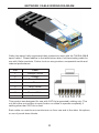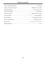
1
Extender for
1.3 over
one CAT-6
EXT-HDMI1.3-1CAT6
User Manual
www gefen com
www.gefen.com
ASKING FOR ASSISTANCE
Technical Support:
Telephone
(800)
Fax
(818)
(818) 772-9100
545-6900
772-9120
Technical Support Hours:
8:00 AM to 5:00 PM Monday thru Friday (PST).
Write To:
Gefen Inc.
c/o Customer Service
20600 Nordhoff St
Chatsworth, CA 91311
www.gefen.com
[email protected]
Notice
Gefen Inc. reserves the right to make changes in the hardware, packaging and
any accompanying documentation without prior written notice.
Extender for HDMI 1.3 over one CAT6 is a trademark of Gefen Inc.
© 2009 Gefen Inc., All Rights Reserved
All trademarks are the property of their respective companies
Rev B
CONTENTS
1
Introduction
2
Operation Notes
3
Features
4
Sender Panel Layout
5
Sender Panel Descriptions
6
Receiver Panel Layout
7
Receiver Panel Descriptions
8
Connecting And Operating The Extender
9
DIP Switch Configuration
11 Network Cable Wiring Diagram
12 Specifications
13 Warranty
INTRODUCTION
Congratulations on your purchase of the Extender for HDMI 1.3 over one CAT6.
Your complete satisfaction is very important to us.
Gefen
Gefen delivers innovative, progressive computer and electronics add-on solutions
that harness integration, extension, distribution and conversion technologies.
Gefen’s reliable, plug-and-play products supplement cross-platform computer
systems, professional audio/video environments and HDTV systems of all sizes
with hard-working solutions that are easy to implement and simple to operate.
The Gefen Extender for HDMI 1.3 over one CAT6
The Gefen Extender for HDMI 1.3 over one CAT6 will send a 1080p@60Hz
HDMI 1.3 signal with 12-bit Deep Color support over a single CAT-6a cable at
distances of up to 175 feet (50m).
HDMI 1.2 is still fully supported and can be extended up to 200 feet (60m)
at resolutions of 1080i/p@60Hz.
Extension of high def nition can now be simplif ed with the use of only a single
CAT-6a cable. Previous solutions used two cables to accomplish this.
The Gefen Extender for HDMI 1.3 over one CAT6 supports the HDMI 1.3
specif cation with features such as Deep Color, Full 1080p HD and compressed
lossless audio formats such as Dolby TrueHD and DTS-HD Master Audio.
The CAT6 extender’s pure digital transmission method insures 100% signal
integrity over this single cable extension solution.
How It Works
The Gefen Extender for HDMI 1.3 over one CAT6 system consists of send and
receive units. The HDMI source (set-top box, DVD player, or gaming console)
connects to the sender unit with the supplied 6-foot HDMI cable. The receiver
unit connects to an HDTV display. One CAT-6a cable links the sender and
receiver together at distances of up to 200 feet. Power is applied to both the
sender and receiver with the included 5V DC power supplies. A perfect image is
now displayed on the remote HDTV display.
Note: This product is an HDCP pass-through device.
1
OPERATION NOTES
READ THESE NOTES BEFORE INSTALLING OR
OPERATING THE EXTENDER FOR HDMI 1.3 OVER ONE CAT6
•
The Extender for HDMI 1.3 over one CAT6 was designed for use with high
quality CAT-6a (augmented) cabling. This unit will either not perform to
specif cation or refuse to operate completely if cabling other than CAT-6a is
used.
• When
f eld terminating CAT-6a cabling please adhere to the TIA/EIA-568-B
specif cation. Please see page 9 for more information.
•
The Extender for HDMI 1.3 over one CAT6 has a maximum distance
rating based on the bandwidth (i.e. resolution and color) of the video being
transmitted. The following specif cations are based on high quality CAT-6a
cabling.
•
200 feet (60 meters) at 1080p/60Hz with up to 10-bit color depth and
with all HDMI 1.2/1.3 audio formats.
•
150 feet (50 meters) at 1080p/60Hz with up to 10-bit color depth and
with all HDMI 1.3 audio formats.
•
66 feet (20 meters) at 1080p/60Hz with up to 12-bit color depth and all
HDMI 1.3 audio formats.
•
The Extender for HDMI 1.3 over one CAT6 is HDMI 1.3 and HDMI 1.2
compliant.
•
This product features HDCP pass-through.
•
By default, Deep Color support is disabled. To enable Deep Color support
please see the DIP switch conf guration guide on page 9. Please note that
once Deep Color is enabled, distance performance will be limited to 150 feet
(50 meters) with premium CAT-6a cabling.
2
FEATURES
Features
•
Flexible extension of high-bandwidth HDMI 1.3 thanks to inexpensive and
widely-available CAT6 cable
•
Audio and video are transmitted digitally over the CAT6 cable for zero signal
loss
•
Single Link Range (maximum resolution): 1080p/60, 12-bit color depth
•
Compliant with HDMI 1.3, HDMI 1.2, HDCP 1.1 and DVI 1.1 standards
•
Supports digital video formats in Deep Color Mode at up to 12bits/color
•
Supports lossless compressed digital audio (Dolby TrueHD, Dolby Digital
Plus and DTS-HD Master Audio)
•
Equalizes incoming HDMI signal and retransmits it with optimal quality
regardless of incoming signal quality
•
Eliminates equipment noise in the viewing environment
•
Improved compensation for cable skew
HDMI 1.3 Features Supported:
•
Dolby TrueHD & DTS Master Audio
•
Deep Color Supported (XV Color)
•
225 MHz (up to 12 bit YUV 444 @ 1080p)
•
CEC Protocol Pass Through
• Lip-Sync
Pass Through
Package Includes
(1) Extender for HDMI 1.3 over one CAT6 Sender
(1) Extender for HDMI 1.3 over one CAT6 Receiver
(1) 6 Foot HDMI to HDMI Cable (M-M)
(2) 5V DC Power Supply
(1) User’s Manual
3
SENDER PANEL LAYOUT
Front Panel
1
2
3
Back Panel
4
4
SENDER PANEL DESCRIPTIONS
1
5V DC Power Receptacle
Connect the included 5V DC power supply between this input and an open wall
power socket.
2
Power LED Indicator
This LED will become active once the included 5V DC power supply is properly
connected between the unit and an open wall power socket.
3
HDMI Input With Mono•LOK Secure Connector
This input will accept a single HDMI source for extension. This input features a
Mono•LOK connector (Gefen part# CAB-HDMI-LCK-XXMM) for a secure cable
connection. This input will accept a standard or Mono•LOK style HDMI cable.
4
Link RJ45 Port
This port is used to connect the sending and receiving units together using a
CAT-6a cable.
5
RECEIVER PANEL LAYOUT
Front Panel
1
2
3
4
Back Panel
5
6
RECEIVER PANEL DESCRIPTIONS
1
Equalization Adjustment
This trimpot is used to equalize the signal to compensate for the extension
distance and the quality/skew variances that are found in different CAT-6a
cabling brands.
2
HDMI Input With Mono•LOK Secure Connector
This input will accept a single HDMI source for extension. This input features a
Mono•LOK connector (Gefen part# CAB-HDMI-LCK-XXMM) for a secure cable
connection. This input will accept a standard or Mono•LOK style HDMI cable.
3
Power LED Indicator
This LED will become active once the included 5V DC power supply is properly
connected between the unit and an open wall power socket.
4
5V DC Power Receptacle
Connect the included 5V DC power supply between this input and an open wall
power socket.
5
Link RJ45 Port
This port is used to connect the sending and receiving units together using a
CAT-6a cable.
7
CONNECTING AND OPERATING THE EXTENDER
How to Connect the Extender for HDMI 1.3 over one CAT6
1.
Connect a HDMI cable (one is supplied) between the HDMI output on a
HDMI source device and the HDMI input on the Extender for HDMI 1.3 over
one CAT6 sending unit.
2.
Connect a single CAT-6a cable between the sending and receiving units.
NOTE: When f eld terminating CAT-6a cabling please adhere to the TIA/EIA568-B specif cation. Please see page 11 for more information.
3.
Connect a HDMI cable (user supplied) between the HDMI input on a HDMI
capable output device (i.e. HDMI display) and the HDMI output on the
Extender for HDMI 1.3 over one CAT6 receiving unit.
4.
Connect the included 5V DC power supplies (two are included) between the
sending and receiving units and open wall power sockets.
5.
Initialize the HDMI output device (i.e. HDMI display) f rst and the HDMI
source device last.
How to Equalize the Extender for HDMI 1.3 over one CAT6
The Extender for HDMI 1.3 over one CAT6 receiving unit has a equalization
Trim to compensate for the extension distance and the quality/skew variances that
are found in different CAT-6a cabling brands. If there is no output video or if output
video has video artifacting and/or video noise, please use the steps below to adjust
the equalization trimpot.
1.
Insert a small f at head tool into the trimpot on the front panel of the
receiver unit.
2.
The trimpot has 8 set positions. Turn the trimpot in a clockwise fashion until
it clicks into the next position. Continue adjusting the trimpot by trying all 8
positions until the issue is resolved.
3.
Carefully remove the adjustment tool.
8
DIP SWITCH CONFIGURATION
DIP SWITCH CONFIGURATION – DEEP COLOR
By default, Deep Color support is disabled (DIP #2 in the OFF position). If Deep
Color support is needed, you can change the position of one of the DIP switches
on the bottom of the receiver:
1.
If the Receiver unit is currently being powered, please disconnect the power
adapter from the unit.
2.
Turn the receiver unit upside down and locate the 4-DIP switch bank on
the bottom of the unit. NOTE: You may need to remove the piece of silver
colored metallic tape to expose the DIP switch bank.
3.
Refer to the image below and locate DIP #2 on the DIP switch bank.
4.
Move DIP 2 to the “ON” position. This will enable Deep Color support and
will be used only if the display supports this deep color. NOTE: DIP 1 must
be in the “OFF” position in order to enable deep color.
5.
Reconnect power to the receiver unit.
9
DIP SWITCH CONFIGURATION
DIP SWITCH CONFIGURATION – EDID
Under normal circumstances, a source device (digital and analog) will require
information about a connected device/display to assess what resolutions
and features are available. The source can then cater its output to send only
resolutions and features that are compatible with the attached device/display.
This information is called EDID (Extended Display Information Data) and a
source device can only accept and read one EDID from a connected device/
display. Likewise, the source can only output one resolution for use by a
connected device/display.
The Extender for HDMI1.3 over one CAT6 uses DIP #1 to control EDID modes.
There are 2 EDID modes; LOCAL and PASSTHROUGH. The LOCAL mode will
create a new EDID by copying all video and audio features of the connected
device but will allow the user to control Deep Color support by the procedure on
the previous page. By default, the unit is shipped in LOCAL mode where DIP
#1 is in the OFF position. The PASSTHROUGH mode will simply allow all video
and audio features of the connected device to pass through to the source device
without control over Deep Color support. DIP #1 can be switched to the ON
position to enable the PASSTHROUGH mode. However, if DIP #1 is switched
to the ON position, enabling Deep Color (DIP #2=ON) will not affect the video
features of the EDID.
When switching DIP #1 between the OFF and ON position, please follow the
procedure outlined below:
1.
Disconnect power from the receiver and locate the DIP switch bank on the
bottom of the unit. NOTE: You may need to remove the piece of silver
colored metallic tape to expose the DIP switch bank.
2.
Refer to the DIP switch image (below) and locate DIP #1 on the DIP switch
bank.
3.
Move DIP #1 to the “ON” or “OFF” position. The “OFF” position will use the
LOCAL EDID mode. The “ON” position sets the unit in PASSTHROUGH
mode, allowing the source to use the original EDID features of the display.
4.
Reconnect power to the receiver unit.
10
NETWORK CABLE WIRING DIAGRAM
Gefen has specif cally engineered their products to work with the TIA/EIA-568-B
specif cation. Please adhere to the table below when f eld terminating cable for
use with Gefen products. Failure to do so may produce unexpected results and
reduced performance.
Pin
Color
1
Orange / White
2
Orange
3
Green / White
4
Blue
5
Blue / White
6
Green
7
Brown / White
8
Brown
12345678
This product was designed for use with CAT-6a (augmented) cabling only. This
unit will either not perform to specif cation or refuse to operate completely if
cabling other than CAT-6a is used.
Each cable run must be one continuous run from one end to the other. No splices
or use of punch down blocks.
11
SPECIFICATIONS
Video Amplif er Bandwidth ....................................................................... 225 MHz
Single Link Max. Resolution ................................................ 1080p/60, 12 bit color
Input DDC Signal ......................................................................... 5 Volts p-p (TTL)
Input Video Signal .............................................................................. 1.2 Volts p-p
HDMI Connector ................................................................ Type A, 19 Pin Female
Link Connector .............................................................................. RJ-45 Shielded
Power Supply ......................................................................... 5V DC @ 0.6A each
Power Consumption ................................................................... 3 Watts (per unit)
Dimensions ...................................................................... 3.3” W x 1.3” H x 3.3” D
Shipping Weight ............................................................................................ 3 lbs.
12
WARRANTY
Gefen warrants the equipment it manufactures to be free from defects in material
and workmanship.
If equipment fails because of such defects and Gefen is notif ed within two (2)
years from the date of shipment, Gefen will, at its option, repair or replace the
equipment, provided that the equipment has not been subjected to mechanical,
electrical, or other abuse or modif cations. Equipment that fails under conditions
other than those covered will be repaired at the current price of parts and labor in
effect at the time of repair. Such repairs are warranted for ninety (90) days from
the day of reshipment to the Buyer.
This warranty is in lieu of all other warranties expressed or implied, including
without limitation, any implied warranty or merchantability or f tness for any
particular purpose, all of which are expressly disclaimed.
1.
Proof of sale may be required in order to claim warranty.
2.
Customers outside the US are responsible for shipping charges to and from
Gefen.
3.
Copper cables are limited to a 30 day warranty and cables must be in their
original condition.
The information in this manual has been carefully checked and is believed to
be accurate. However, Gefen assumes no responsibility for any inaccuracies
that may be contained in this manual. In no event will Gefen be liable for
direct, indirect, special, incidental, or consequential damages resulting from
any defect or omission in this manual, even if advised of the possibility of such
damages. The technical information contained herein regarding the features and
specif cations is subject to change without notice.
13