1
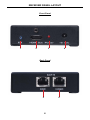
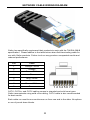
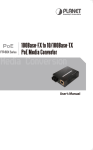
1:5 Splitter For
Over CAT-5
EXT-HDMI-CAT5-145
User Manual
www.gefen.com
f
ASKING FOR ASSISTANCE
Technical Support:
Telephone
Fax
(818) 772-9100
(800) 545-6900
(818) 772-9120
Technical Support Hours:
8:00 AM to 5:00 PM Monday thru Friday.
Write To:
Gefen Inc.
c/o Customer Service
20600 Nordhoff St
Chatsworth, CA 91311
www.gefen.com
[email protected]
Notice
Gefen Inc. reserves the right to make changes in the hardware, packaging and
any accompanying documentation without prior written notice.
1:5 Splitter For HDMI Over CAT-5 is a trademark of Gefen Inc.
© 2008 Gefen Inc., All Rights Reserved
All trademarks are the property of their respective companies
Rev X1
CONTENTS
1
Introduction
2
Operation Notes
3
Features
4
Sender Panel Layout
5
Sender Panel Descriptions
6
Receiver Panel Layout
7
Receiver Panel Descriptions
8
Connecting And Operating The 1:5 Splitter For HDMI Over CAT-5
9
EDID Modes
10 Equalization & Boost Settings
11 Network Cable Wiring Diagram
12 Specifications
13 Warranty
INTRODUCTION
Congratulations on your purchase of the 1:5 Splitter For HDMI Over CAT-5. Your
complete satisfaction is very important to us.
Gefen
Gefen delivers innovative, progressive computer and electronics add-on solutions
that harness integration, extension, distribution and conversion technologies.
Gefen’s reliable, plug-and-play products supplement cross-platform computer
systems, professional audio/video environments and HDTV systems of all sizes
with hard-working solutions that are easy to implement and simple to operate.
The Gefen 1:5 Splitter For HDMI Over CAT-5
The Gefen 1:5 HDMI Over CAT5 Distribution Amplifier allows you to distribute
HDMI video to 4 remote HDTV displays and to 1 local HDTV displays via
inexpensive and standard CAT5 cables.
How It Works
Simply plug your video source into the Gefen 1:5 HDMI Over CAT5 D.A. Sender
unit, then run an HDMI cable to your local HDTV displays. Then connect your
CAT5 cables to 1:5 HDMI Over CAT5 D.A. Sender unit, and finally connect a pair
of CAT5 cables to each of the 4 HDMI CAT5 D.A. Extreme Receivers at remote
HDTV display.
Note: CAT5 cable extensions may be up to 300 feet (1080i) or 150 ft (1080p).
1
OPERATION NOTES
READ THESE NOTES BEFORE INSTALLING OR
OPERATING THE 1:5 SPLITTER FOR HDMI OVER CAT-5
•
1:5 Splitter For HDMI Over CAT-5 will split the HDMI signal to 5 HDMI
outputs. 4 of these outputs can be sent over CAT-5, CAT-5e or CAT-6 cables
to remote locations while the last output can be used for local use.
•
An short HDMI jumper cable (4 are included) must be connected from each of
the lower board HDMI outputs to each of the upper board HDMI inputs to use
the extension capabilities of the 1:5 Splitter For HDMI Over CAT-5.
•
The maximum cable extension is 300 feet (91 meters) for video resolutions
of 1080i and below.
•
The maximum cable extension is 150 feet (45 meters) for video resolutions
of 1080p.
•
If EMI is present anywhere near the CAT-5, CAT-5e or CAT-6 video cable
runs, it may be necessary to use shielded cable. This is to prevent possible
interference from degrading the video signal. Using shielded cable, however,
will reduce the maximum distance that the cable can be run.
•
Extensions under 130 feet can use Auto EQ (which is on by default).
Extensions over 130 feet will require you to manually EQ your signal (see
page 10).
•
Each cable run must be one continuous run from one end to the other. No
splices or use of punch down blocks.
•
High quality CAT-6 cabling should be used for maximum performance.
•
Do not use stranded or low/no skew cabling. Solid core cabling should be
used for maximum performance.
•
HDMI 1.2 Compliant.
•
HDCP Compliant.
2
FEATURES
Features
•
HDMI Video Distribution to up to 5 local displays or 4 remote
•
300 ft. at 1080i; 150-ft range for 1080p
•
Maintains high resolution video - beautiful, sharp HDTV resolutions up to
1080p, 2k, and computer resolutions up to 1920 x 1200 are easily achieved
•
Enables greater versatility when installing multiple HDMI displays
•
HDCP Compliant
Package Includes
(1) 1:5 HDMI CAT5 Distribution Amplifier (Sender Unit)
(1) 24V DC Power Supply
(4) EXT-HDMI-CAT5-DAR (Receiver Unit)
(4) 5VDC Power Supply
(1) 6 Foot HDMI M-M Cable
(4) 1 Foot HDMI M-M Cable
(1) User’s Manual
3
SENDER PANEL LAYOUT
Front Panel
1 2 3
Back Panel
4
7
8
5
4
9
5
4
9
5
9
4
4
5
9
6
9
SENDER PANEL DESCRIPTIONS
1
Reset Button
Pressing this button will reset the unit and cause the source to re-detect the
EDID. This is useful for when the EDID mode on the rear panel is changed.
2
Active LED Indicator
This LED will become active when a valid link between the 1:5 Splitter For HDMI
Over CAT-5 sender and the source has been established.
3
Power LED indicator
This LED will become active once the included 24V DC power supply has been
properly connected to the sender unit.
4
RJ-45 Extension Ports
There are 2 RJ-45 ports for each of the 4 HDMI extensions to remote locations.
There is one port labeled DDC and once port labeled Video. Both ports must be
used for HDMI extension.
5
HDMI Jumper Input Port
A short jumper cable (included) from the lower HDMI output ports must be
connected to these input ports to use the extension feature. There are 4 input
ports that can be used by up to 4 of the 5 HDMI output ports.
6
24V DC Power Input
Connect the included 24V DC power adapter between this input port and an
available wall power socket.
7
EDID Mode Switch
This switch will determine which EDID mode is used. The two modes are
Internal EDID and External EDID. Please see page 9 for information on how this
feature is used.
8
HDMI Input Port
Connect the HDMI source device to this input port. The HDMI signal that is
connected to this input port will be mirrored to the 5 output ports on the rear
panel.
9
HDMI Output Ports
There are 5 HDMI output ports that are available for connection to either the
extension jumper inputs (up to 4 outputs) or to local HDMI capable displays.
5
RECEIVER PANEL LAYOUT
Front Panel
1
2
3
4
Back Panel
5
6
6
RECEIVER PANEL DESCRIPTIONS
1
Equalization Trim Pot
This Trim Pot is used to equalize the incoming HDMI signal to account for
variances in CAT cable skew. By default, the Auto EQ feature is enabled and
this Trim Pot does not need to be adjusted. In the event that manual EQ mode is
enabled, this Trim Pot will be used to equalize the signal.
2
HDMI Output Port
Connect an HDMI capable display to this output port.
3
Power LED Indicator
This LED will become active once the included 5V DC power supply has been
properly connected to the 1:5 Splitter For HDMI Over CAT-5 receiver unit.
4
Power LED Indicator
Connect the included 5V DC power adapter between this input port and an
available wall power socket.
5
RJ-45 DDC Port
A CAT-5, CAT-5e or CAT-6 cable must be connected between the receiver and
sender. This cable carries DDC and HDCP data. Most source devices will not
operates properly without this data.
6
RJ-45 Video Port
A CAT-5, CAT-5e or CAT-6 cable must be connected between the receiver and
sender. This cable carries Video and Audio data.
7
CONNECTING AND OPERATING THE
1:5 SPLITTER FOR HDMI OVER CAT-5
How to Connect the 1:5 Splitter For HDMI Over CAT-5
1.
Connect the HDMI source device to the 1:5 Splitter For HDMI Over CAT-5
sender unit using the supplied HDMI cable.
2.
Connect up to 4 of the HDMI outputs to the HDMI jumper inputs using the
supplied short HDMI jumper cables. The fifth port can be used for local
HDMI output to a display. Alternately, any or all output ports can be used to
route HDMI to local displays, bypassing the HDMI extension feature.
3.
For each HDMI extension, connect a pair of user supplied CAT-5, CAT-5e or
CAT6 cables between an open pair of RJ-45 extension ports on the sender
and the pair of RJ-45 ports on a receiver.
NOTE: When field terminating CAT cable, please adhere to the TIA/EIA568-B specification. Please see page 11 for details.
4.
Connect a HDMI capable display to the receiver using a user supplied HDMI
cable.
5.
Connect the included 24V DC power adapter to the sending unit and one of
the included 5V DC power adapters to each of the receivers.
6.
Power on the displays first and then the source device.
NOTE: Video may not immediately appear. If this is the case, please refer to
the next section for instructions on how to change EDID modes and adjust
equalization.
8
EDID MODES
EDID (Extended Display Identification Data) contains information on the
resolution and general capabilities of a display device. This information is used
by the source device to output a compatible signal that the display can accept.
This information can even be used by some source devices to limit the output
of resolutions and features that the display is not capable of accepting. In single
source and single device setup, EDID can effectively ensure compatibility with
display and source. The 1:5 Splitter For HDMI Over CAT-5 replicates a single
HDMI input from a source to up to 5 HDMI capable devices. However, since the
source device can only output one type of audio and video signal (resolution,
features, number of audio channels, audio format, etc.) based on the EDID
it receives, all connected HDMI devices must have common audio and video
capabilities for successful replication to occur.
The source of the EDID can be selected using the EDID mode feature. There are
two sources from which the EDID can be polled and then transferred back to the
source device. The External mode uses the EDID from the display connected to
the first HDMI output port. The Internal mode will use and built-in EDID that is
stored in the unit. The Internal EDID mode supports resolutions of up to 1080p
and includes common audio features.
How to Change EDID Modes
1.
Locate the EDID Mode Switch on the rear panel of the 1:5 Splitter For HDMI
Over CAT-5 sender unit.
2.
Note the switch’s current position and change the EDID mode to either INT
(Internal) or EXT (External) by toggling the switch.
3.
Press the reset button on the front panel to reset the connection to the
source device so that it can re-detect the new EDID change.
9
EQUALIZATION & BOOST SETTINGS
Each 1:5 Splitter For HDMI Over CAT-5 receiver contains a Dip Switch bank
located on the underside of the unit. This bank of 4 Dip Switches are covered
with a piece of silver metallic tape. These Dip Switches will modify boost settings
and change the equalization mode.
EQUALIZATION MODES
Dip Switch 1 is used to select the equalization mode. There are 2 EQ modes
to select from. Auto Equalization (Dip Switch 1 = Off, default) will automatically
attempt to equalization the incoming signal and eliminate and digital noise that
may occur due to variances in cable skew. Manual Equalization (Dip Switch 1 =
ON) will allow the user to manually EQ the signal using the Trim Pot located on
the front panel of the receiver. By default, Auto Equalization is set and is effective
for CAT cable runs of up to 130 feet. Distances greater than 130 feet should be
manually equalized. Use the table below for quick reference of the EQ Dip Switch
modes.
Receiver Auto EQ Dip Switch Settings
Setting
Switch 1
Switch 2
Manual EQ
ON
Not Used
Auto EQ (Default)
OFF
Not Used
BOOST MODES
Dip Switches 3 and 4 are used to specify the boost strength of the signal from the
1:5 Splitter For HDMI Over CAT-5 sender. This feature will boost the signal when
long distances of cable are used and will also help the signal reach the receiver
when low quality cable is used. There are not set distance rules in regards to this
setting (due to the variances in cable quality), so it is recommended that the user
try all settings, starting with no boost, when troubleshooting issues. Please refer
to the table below for the 4 different Dip Switch combinations.
Receiver Boost Dip Switch Settings
Setting
Switch 3
Switch 4
No Boost (Default)
OFF
OFF
Medium Boost
OFF
ON
High Boost
ON
OFF
Very Low Boost
ON
ON
10
NETWORK CABLE WIRING DIAGRAM
Gefen has specifically engineered their products to work with the TIA/EIA-568-B
specification. Please adhere to the table below when field terminating cable for
use with Gefen products. Failure to do so may produce unexpected results and
reduced performance.
Pin
Color
1
Orange / White
2
Orange
3
Green / White
4
Blue
5
Blue / White
6
Green
7
Brown / White
8
Brown
12345678
CAT-5, CAT-5e, and CAT-6 cabling comes in stranded and solid core types.
Gefen recommends using solid core cabling. CAT-6 cable is also recommended
for best results.
Each cable run must be one continuous run from one end to the other. No splices
or use of punch down blocks.
11
SPECIFICATIONS
Video Amplifier Bandwidth ....................................................................... 165 MHz
Input Video Signal .............................................................................. 1.2 Volts p-p
Input DDC Signal ......................................................................... 5 Volts p-p (TTL)
Single Link Range ................................................................... 1080p/1920 x 1200
HDMI Video Connector ...................................................... Type A, 19 Pin Female
Link Connector .............................................................................. RJ-45 Shielded
Power Supply ............................................................................................ 24V DC
Power Consumption ....................................................................... 50 Watts (max)
Dimensions Sender .............................................. 17.125” W x 3.50” H x 5.375” D
Dimensions Receiver ................................................... 3.25” W x 1.25” H x 3.4” D
Shipping Weight .......................................................................................... 12 lbs.
12
Rev X1
20600 Nordhoff St., Chatsworth CA 91311
1-800-545-6900
818-772-9100
www.gefen.com
fax: 818-772-9120
[email protected]