1
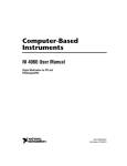
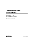
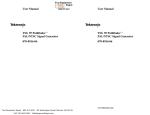
6060 Spine Road
Boulder, CO 80301 USA
T 303 444 2009
F 303 444 9543
Sievers 800 TOC Analyzer Flow Switch Upgrade
(Flow Switch Kit and Firmware 2.12 CBI)
1. Purpose: To describe the mechanical installation for the flow switch, firmware 2.12 CBI
upgrade installation and operation of the flow switch.
2. Scope:
This procedure describes the activities required to install the flow switch and
firmware 2.12 CBI in all Model 800 series TOC analyzers. For TURBO analyzers,
this procedure describes the installation and configuration of the flow switch.
Turbo Analyzers will omit the firmware installation section.
3. Materials and Tools:
7/16" open end or adjustable wrench
1/2" open end wrench
Flat head screwdriver
Phillips head screwdriver
Scriber
Teflon® tape
WARNINGS:
•
A 60-micron filter must be used to ensure proper operation of the flow switch.
•
Do not over tighten any fitting.
•
Switch orientation should be no more than 15° from vertical alignment.
•
Do not install units near ferrous metals, magnets or electromagnetic fields.
•
Please review the enclosed Operation and Maintenance Manual. There have
been features added to the analyzers. These additions are dependent upon
the firmware version and software version currently in use.
GE Analytical Instruments, Inc. ©2005H
Page 1 of 16
DIN 30001 Rev. E
TOC,FLOW SWITCH UPGRADE 2.12CBI
BINARY
INPUT
MODULE
FLOW
SWITCH
PFA
TUBING
STAINLESS
STEEL
TUBING
FIGURE ONE: Flow Switch Kit
4.
Mechanical installation
Refer to Figures One or Two for this procedure. Reference will depend on orientation
of tubing from regulator.)
4.1.
4.2.
4.3.
4.4.
4.5.
4.6.
4.7.
4.8.
4.9.
4.10.
Remove the outlet PFA tube connector from the pressure regulator of the analyzer.
Detach the regulator from the analyzer by removing the two screws on the bottom of
the mounting bracket making sure not to lose the fiber spacers.
Remove the elbow from the outlet side of the regulator and clean the port and
connector threads of any Teflon® tape remains. Reapply 4 wraps of Teflon tape to
the elbow and screw the fitting back into the regulator ending with the tube fitting
pointing down as shown.
Reinstall the regulator to the analyzer with the two screws making sure to use the
fiber spacers.
Remove the PFA tube from the inlet of the sampling block.
Position the flow switch and secure the end of the stainless steel U-tube to the
regulator outlet. Wires must point up to have a calibrated normally open switch.
Secure the PFA tube from the outlet of the switch to the inlet of the sampling block.
Connect the wires from the flow switch to the Binary Input Module, polarity not
important to the binary module.
Route the electrical cable as desired and plug the end into the AUX PORT on the
opposite side of the instrument.
If installing the switch on a TURBO analyzer, proceed to 6, if not proceed to 5.
GE Analytical Instruments, Inc. ©2005H
Page 2 of 16
DIN 30001 Rev. E
TOC,FLOW SWITCH UPGRADE 2.12CBI
FLOW SWITCH
FLOW
SWITCH
OUTLET
SAMPLING BLOCK
REGULATOR
P2
BINARY
INPUT
MODULE
FLOW
SWITCH
INLET
REGULATOR
OUTLET
REGULATOR
INLET
SAMPLE
BLOCK
INLET
60 MICRON FILTER
FIGURE TWO: Installed Flow Switch on the Model 800 TOC Analyzer
5.
Firmware installation
5.1.
Print the current constants.
Any IBM compatible dot matrix printer with a parallel printer cable equipped with
a 25pin connection may be used. It is very advantageous to have a printout of the
constant values.
If a printer is not available, go to Step 5.2.
5.1.1.
5.1.2.
5.1.3.
5.1.4.
5.2.
From the RUN-TIME Menu, press STOP TOC.
The MAIN Menu will be displayed select SETUP, press Enter.
Select PRINTER, press Enter.
Select PRINT CONSTANTS, press Enter.
If a printer is not available, access the FACTORY ACCESS Menu to scroll through and
record constant values on the Constants Record Form within this procedure.
Constant values for C1THERM A, C2THERM A, C1THERM B, AND C2THERM B will be
rounded values. The displayed constant value will differ from the printed constant
value. This should not impact the analyzer’s performance. Contact GE Analytical
Instruments for the last printed Constant Value list, if desired.
5.2.1. From the MAIN menu select CALIBRATE, press Enter.
5.2.2. Select TC ZERO OFFSET, press Enter.
GE Analytical Instruments, Inc. ©2005H
Page 3 of 16
DIN 30001 Rev. E
TOC,FLOW SWITCH UPGRADE 2.12CBI
TC ZERO CORRECTION
ENTER
-1.3250000
ENT = SAVE CHAR/NUM
CLR = RESTART/EXIT
ARROWS = CHANGE CHAR
CLEAR
FIGURE THREE: TOC ZERO OFFSET Screen
5.2.3. Enter 911 by using the arrows, and then press Enter.
ENTERING 911 WILL IN, NO WAY AFFECT THE VALUE OF THE
TC ZERO CORRECTION.
FACTORY ACCESS V. 0.00
ENTER
SET SYRNGE
ERASE ERRS SET SERVO
PRNT SETUP DUMP RAM
CLEAR
SET EEPROM SET 4-20MA
SYRNGE MOV SYRNG PULS
FIGURE FOUR: FACTORY ACCESS Menu
5.2.4. Using the arrows, select SETEEPROM, and press Enter.
5.2.5. Constants will be displayed in the sequence listed on the Constants Record
Form. Record each constant value on the form contained within this
document.
IMPORTANT:
It is critical that this Printout or Constants Record Form is retained for
comparison to the Constant Printout or Record Form at end of upgrade
procedure. These Constants will have to be checked and any variations
must be corrected after the upgrade is completed.
5.2.7. Record Dates and Percents for consumables on the Constants Record
Form. These will need to be reentered after upgrade.
5.2.8. From the MAIN MENU select CONSUMABLES, press Enter.
LAMP
OXIDIZER
ACID
PUMP TUBING
ENTER
CLEAR
REAGENT FLUSH
FIGURE FIVE: Consumables Menu
GE Analytical Instruments, Inc. ©2005H
Page 4 of 16
DIN 30001 Rev. E
TOC,FLOW SWITCH UPGRADE 2.12CBI
5.2.9. Select each consumable, press Enter. Write the information on
the Printout or the Constants Record Form. Record date and
percent left for the OXIDIZER. Record the percent left for the
LAMP, PUMP TUBING and ACID.
5.2.10. REAGENT FLUSH is not a consumable to record.
5.2.11. Print or record Errors and Warnings if desired.
5.2.12. Data on the Ram Card will not be erased or affected in any way
upon performing this procedure.
5.3.
Replace the EPROM chip (IC chip).
CAUTION:
Prior to performing the following instructions it is essential, to be grounded
according to established procedures. Failure to be properly grounded will
result in damage to the EPROM Chip and void the warranty.
5.3.1. Turn off the analyzer power and disconnect the power cord.
5.3.2. Lift the analyzer cover and locate the PC electronics board, refer to
Figure Six.
5.3.3. Depending on the type of chip holder in the analyzer, different
techniques are required to replace the existing EPROM with the EPROM
labeled 2.12CBI. Facing the analyzer’s front panel, locate the EPROM
socket on the left side of the PC electronics board near the rear of the
analyzer. If the chip socket has a metal lever at the top, it is a Zero
Insertion Force Socket (Step 5.3.4). If the chip socket does not have a
lever, it is a Low Profile Socket (step 5.3.5). Figure Six illustrates the low
profile socket. Use the appropriate instruction to replace the chip.
IC SOCKET
(POWER SUPPLY)
PC BOARD
FRONT OF TOC
PC BOARD
SOCKET
SCREW DRIVER HERE
UPPER TAB
RIGHT INDEX
FINGER HERE
CARRIER
EPROM
LOWER TAB
NOTCH
FIGURE SIX: Low Profile Socket Replacement
GE Analytical Instruments, Inc. ©2005H
Page 5 of 16
DIN 30001 Rev. E
TOC,FLOW SWITCH UPGRADE 2.12CBI
5.3.4. Replace the EPROM from a Zero Insertion Force Socket.
5.3.4.1. There is a small brass lever on the socket to secure the EPROM
chip. It should be in the locked position (end of the lever close to
the PC board).
5.3.4.2. Prior to removing the existing EPROM chip, open the protected
packaging and place the upgrade EPROM chip on the
packaging.
5.3.4.3. To remove the existing chip, hold the EPROM chip with one hand
and unlock the socket with the other by pushing the end of the
lever away from the PC board. Pull the existing EPROM chip
straight out of the socket, note NOTCH position, and place it on
the protected packaging that surrounded the upgrade EPROM
chip.
5.3.4.4. To install the upgrade 2.12CBI EPROM chip in the socket, locate
the NOTCH on the chip and ensure that the notch is facing
down. Align the pins to the socket openings and insert the
EPROM chip in the socket. While pressing on the EPROM chip
push the locking lever to the locked position (toward the PC
board) to secure the EPROM chip in place.
CAUTION:
Be sure the NOTCH of the EPROM chip is toward the bottom of the analyzer
and all the pins are engaged into the socket. Improper or forced installation
will cause irreversible damage to the chip.
5.3.5. Replace the EPROM Chip from a Low Profile type Socket.
5.3.5.1. The EPROM socket consists of two parts, the main socket that is
soldered to the PC board and the keyed carrier for holding the
EPROM chip refer to lower left corner of Figure Six. Note: The
keyed carrier will only go in the socket in one direction.
5.3.5.2. Prior to removing the existing EPROM chip, open the protected
packaging and place the new EPROM chip on the packaging.
5.3.5.3. To remove the existing chip, place the screwdriver at a right
angle on the upper tab of the socket. Once carrier is pried away
from the socket, slide screwdriver under the carrier and rock the
chip and carrier by applying force to the top with your finger
and then with the screwdriver along the length of the carrier.
Pull the chip and carrier from the socket, see lower right corner
of Figure Six. Be sure to pull the chip out straight so as not to
damage the EPROM chip pins.
5.3.5.4. Place the chip and the carrier on the protected packaging that
contained the upgrade chip.
5.3.5.5. To install the upgrade EPROM chip into the carrier, note the
location of the NOTCH of the existing chip and remove it from
the carrier. Replace it with the upgrade chip, ensuring that the
orientation of the NOTCH is the same. If the chip falls from the
GE Analytical Instruments, Inc. ©2005H
Page 6 of 16
DIN 30001 Rev. E
TOC,FLOW SWITCH UPGRADE 2.12CBI
carrier, gently press the pins of the chip to conform to the
carrier.
CAUTION:
Be sure the NOTCH of the EPROM chip is toward the bottom of the analyzer
and all the pins are engaged into the socket. Improper or forced
installation will cause irreversible damage to the chip.
5.3.5.6. Align the key of the assembly with the key position of the socket
and gently press the EPROM chip and carrier assembly evenly
into the PC board socket until fully inserted. A fully inserted
assembly will be flush with the socket housing on both sides. A
click will be heard when the chip and carrier are firmly in place.
CAUTION:
Do not force the carrier into the socket. If it does not go into the socket,
ensure that the key is in the proper location and the IC chip pins are not
bent.
If the chip and carrier are not properly installed, a blank blue screen will
appear on the front panel display.
5.4.
Once the EPROM chip is installed, close the analyzer.
5.4.1. Place the replaced chip in the protected packaging for proper disposal
according to local regulations.
5.4.2. Reconnect the power to the analyzer.
5.5.
Turn the analyzer on while depressing the UP arrow.
5.5.1. The analyzer will display message screens. The analyzer will set default
constants, dates, and times.
5.5.2. A screen stating SYSTEM INITIALIZATION IS COMPLETE will appear, press any
key to return to the MAIN Menu.
5.5.3. After all procedures are complete, pressing any key will return the analyzer to
the MAIN Menu.
NOTE:
Following the installation of the new EPROM, the instrument may be ready to
recalibrate the syringes, this process will take 3-4 minutes. Allow the process
to occur. Additionally, a non-fatal error #38 can be expected.
5.6.
Print or record the new memory constants by following Step 5.1.
5.6.1. Verify new constant values. There are new constant values to enter and some
variations must be reentered to return the constants to the prior values. Use
the Constants Record Form within this procedure as a guide. To enter constant
values there is limited access to the FACTORY ACCESS menu.
GE Analytical Instruments, Inc. ©2005H
Page 7 of 16
DIN 30001 Rev. E
TOC,FLOW SWITCH UPGRADE 2.12CBI
CAUTION:
IF THERE ARE ANY VARIATIONS, CONSTANTS MUST BE ENTERED THROUGH
THE FACTORY ACCESS MENU. ACCESS TO THIS MENU IS LIMITED AND WILL
REQUIRE A PASSWORD. ENSURE THAT ACCESS TO THIS MENU IS
RESTRICTED. ANY WRONGFUL DATA ENTRY WILL RESULT IN THE ANALYZER
PERFORMING OUT OF SPECIFICATION!!!
5.6.1.1. From the MAIN menu select SETUP, press Enter.
5.6.1.2. From the SETUP menu, select CALIBRATE, press Enter.
5.6.1.3. Select TC ZERO OFFSET, press Enter.
TC ZERO CORRECTION
ENTER
-1.3250000
ENT = SAVE CHAR/NUM
CLR = RESTART/EXIT
ARROWS = CHANGE CHAR
CLEAR
FIGURE SEVEN: TOC ZERO OFFSET Screen
5.6.1.4. Enter 911 by using the arrows, and then press Enter.
NOTE:
ENTERING 911 WILL IN NO WAY AFFECT THE VALUE OF THE TC ZERO
CORRECTION.
FACTORY ACCESS V. 0.00
ENTER
ERASE CARD
ERASEERRS ANALOG #
PRNT SETUP FACTMODES
CLEAR
SETEEPROM RAW DATA
SET 4-20MA
COND ZERO
FIGURE EIGHT: FACTORY ACCESS Menu
5.6.1.5. Using the arrows, select SETEEPROM, and press Enter.
5.6.1.6. Constants will be displayed in the same order as the printed or
recorded constants list.
5.6.1.7. Once scrolling through the list has begun, the entire list must be
seen. DO NOT PRESS THE CLEAR KEY. Pressing the Clear key will
result in the erasing of the Constant Value entered. To move up
or down the list use the arrow keys.
C1 CONST:
0.800600
ENT = CHANGE VALUE
CLR = SET TO DEFAULT
ARROWS = NEXT VALUE
GE Analytical Instruments, Inc. ©2005H
Page 8 of 16
ENTER
CLEAR
DIN 30001 Rev. E
TOC,FLOW SWITCH UPGRADE 2.12CBI
FIGURE NINE: First Constant Screen
5.6.1.8. Use the Constants Record Form as a guide. If a number is on
the Constants Record Form, the new constant value must be
that value. If the Constants Record Form states “same as prior
value”, change the value to match. If the constants Record
Form states “do not change”, do not change the value.
5.6.1.9. If the value displayed does not have to be changed, press the
UP arrow key to progress to the next constant value on the list.
5.6.1.10. If the value displayed must be changed, press Enter. Use the
arrows to scroll to the first digit/decimal/minus sign, press Enter
to save that character and go to the next.
5.6.1.11. When upgrading Model 810 and Model 820 from very early
Firmware revisions, it is critical to check that the constant
setting for AC FREQUENCY is set to 50. Model 800 must be set to
60. There are some 100 volt analyzers that are 60Hz, in this
case use the C1 XFER. C2 Xfer and TC/IC OFFSET of the
appropriate frequency. The 50 Hz calibration constants are
toward the bottom of the list.
5.6.1.12. Press Enter to save the constant value. Press the Up arrow key
to progress to the next constant value. Press the Down Arrow to
return to previous constant value. Press Clear to return the
constant to its default value.
5.6.1.13. There may be new constants when upgrading, make all
changes as instructed on the Constants Record Form to keep
the analyzer in specification.
5.6.1.14. When the last constant value (LINERARITY VAR.E) has been
verified, the following screen will appear:
END OF EEPROMLIST
EXIT? ENT = Y
CLR = N
ENTER
CLEAR
FIGURE TEN: Set EEPROM Exit screen
5.6.1.15. Pressing Enter will return to the MAIN Menu.
5.6.1.16. Pressing Clear will return to the last value of the constant list.
Scroll using the DOWN arrow to change any constant value.
Scroll back to the end of the list to exit. Press Enter to return to
the MAIN Menu.
5.7.
From the MAIN Menu, a final configuration must be performed. Before the analyzer
may be used, the flowrates and the sampling mode must be reset. Refer to the user
manual for more a detailed procedure.
5.7.1. Set Clock – From the MAIN Menu, select SETUP. Press Enter. Select CLOCK.
Press Enter. Use the arrow buttons to scroll to each digit option. Press Enter
GE Analytical Instruments, Inc. ©2005H
Page 9 of 16
DIN 30001 Rev. E
TOC,FLOW SWITCH UPGRADE 2.12CBI
to save digits. After resetting the clock, Warning 35 will occur until the power
has been cycled two times.
5.7.2. Set Flowrates – The Firmware allows selection of different flow rates for online sampling and grab (container) sampling. The grab flow rates can be
viewed and changed from the MAIN – SETUP/REAGENTS menu and from the
GRAB SAMPLING – SETUP/REAGENTS menu. Make sure to view and change
the desired flow rates for the sample mode being used.
5.7.3. From the SETUP menu, choose REAGENTS. From the REAGENTS menu, choose
ONLINE FLOW RATES. Set both reagent flowrates to the desired level. Select
the sampling mode.
5.7.3. From the SETUP menu, choose SAMPLE MODE.
5.7.3.1. Select ON LINE SAMPLING or GRAB SAMPLING. If GRAB SAMPLING is
selected, START TOC will access the GRAB SAMPLING menu, where
additional setup options may be implemented.
5.7.4. Select Frequency, only if AC FREQ. SETTING” is set to 50 for the 810 and 820
analyzers.
5.7.5.1. From SETUP, select 50/60HZ.
5.7.5.2. Select the appropriate Frequency for the analyzer.
5.7.6. Reset Acid/Oxidizer/UV Lamp/Pump Tubing dates and percentages.
5.7.6.1. Select CONSUMABLES from the MAIN Menu, press Enter.
5.7.6.2. Select ACID, OXIDIZER, UV LAMP, or PUMP TUBING, press Enter.
5.7.6.3. For the oxidizer, select SET % LEFT and enter the percent recorded on
the printout or the Constants Record Form. Use the arrow keys to
scroll through digits and press the Enter key to set the digits. Select
SET INSTALL DATE, press Enter. Use the arrow keys to scroll through
digits and press the Enter key to set the digits.
5.7.6.4. For the ACID, LAMP and PUMP TUBING, select SET % LEFT and enter the
percent recorded on the printout or the Constants Record Form. Use
the arrow keys to scroll through digits and press the Enter key to set
the digits.
GE Analytical Instruments, Inc. ©2005H
Page 10 of 16
DIN 30001 Rev. E
TOC,FLOW SWITCH UPGRADE 2.12CBI
Constants Record
CONSTANT VALUE
NAME
C1 CONST:
C2 CONST:
C1 THERM A:
C2 THERM.A:
C1 THERM B:
C2 THERM B:
C1 THERM C:
C2 THERM C:
C1 XFER (60Hz):
C2 XFER (60Hz):
C1 COND:
C2 COND:
C1 TEMP:
C2 TEMP:
STEPPER 1:
STEPPER 2:
SOAK 1:
SOAK 2:
FLUSH 1:
FLUSH 2:
SYRINGE 1:
SYRINGE 2:
BAUD:
STEPFILL 1:
STEPFILL 2:
STEPZERO:
DELAY:
CELL1 ZERO:
CELL2 ZERO:
COND SKIP:
A/D NOISE LEVEL:
TOC MODE:
PRINTER COLUMS:
PRINTER BREAK:
PRINTER TIME:
SERVO FILL PULSE:
SERVO DRAIN PULSE:
SLOPE WINDOW:
ANALOG MIN:
GE Analytical Instruments, Inc. ©2005H
CONSTANT VALUE AFTER
UPGRADE
CONSTANT VALUE PRIOR
TO UPGRADE
Same as prior value
Same as prior value
Same as prior value
Same as prior value
Same as prior value
Same as prior value
Same as prior value
Same as prior value
Same as prior value
Same as prior value
Same as prior value
Same as prior value
Same as prior value
Same as prior value
Analyzer will automatically enter
this value – do not change.
Analyzer will automatically enter
this value – do not change.
300
300
60
60
0.01445
0.01445
9600
20000
20000
24
24
10
10
8
60
Same as prior value
Same as prior value
0
0
Analyzer will automatically enter
this value – do not change
Analyzer will automatically enter
this value – do not change
60
Same as prior value
Page 11 of 16
DIN 30001 Rev. E
TOC,FLOW SWITCH UPGRADE 2.12CBI
CONSTANT VALUE
NAME
ANALOG MAX:
TOTAL ACID VOL:
TOTAL OXID VOL:
ALARM #1 TYPE:
ALARM #2 TYPE:
ALARM #1 LEVEL:
ALARM #2 LEVEL:
LAMP MAX DAYS:
HOSE MAX DAYS:
OXID MAX DAYS:
HYSTERESIS CNT:
TC/IC OFFSET (60Hz):
SLOPE PPM/HOUR:
S1 TOC ACID FLOW:
S1 TOC OXID FLOW:
S2 TOC ACID FLOW:
S2 TOC OXID FLOW:
S3 TOC ACID FLOW:
S3 TOC OXID FLOW:
S4 TOC ACID FLOW:
S4 TOC OXID FLOW:
REFILL DELAY:
SERIAL NUMBER:
TC TEMP CORR A:
TC TEMP CORR B:
TC TEMP CORR C:
TC TEMP CORR D:
IC TEMP CORR A:
IC TEMP CORR B:
IC TEMP CORR C:
IC TEMP CORR D:
DAC RANGE MIN:
DAC RANGE MAX:
PRINTOUT INTERVAL:
SAMPLE STEPZERO:
SAMPLE FLOWRATE:
SYRINGE MAX POINT:
SYRINGE MAX RANGE:
SYRINGE ZERO RANGE:
REAGENT FLUSH REPS:
NUMBER OF STREAMS:
AC FREQ. SETTING:
GE Analytical Instruments, Inc. ©2005H
CONSTANT VALUE AFTER
UPGRADE
CONSTANT VALUE PRIOR
TO UPGRADE
Same as prior value
150
150
Same as prior value
Same as prior value
Same as prior value
Same as prior value
182
365
90
40
Same as prior value
5000
0.2
0
0.4
0.2
0.75
0.5
0.75
2.5 or 2.0
same as prior value
15
Same as prior value
2.03149
-0.0593627
0.00101571
-5.7161E-06
2.57516
-0.0975902
0.00194737
-1.34084E-05
Same as prior value
Same as prior value
0
100
55 or 71
same as prior value
31000
3100
150
2
4
Same as prior value
Page 12 of 16
DIN 30001 Rev. E
TOC,FLOW SWITCH UPGRADE 2.12CBI
CONSTANT VALUE
NAME
C1 XFER (50Hz):
C2 XFER (50Hz):
TC/IC OFFSET (50Hz):
IC COND.OFFSET:
TC COND.OFFSET:
LINEARITY VAR.A:
LINEARITY VAR.B:
LINEARITY VAR.C:
LINEARITY VAR.D:
LINEARITY VAR.E:
CONSTANT VALUE AFTER
UPGRADE
CONSTANT VALUE PRIOR
TO UPGRADE
Same as prior value
Same as prior value
Same as prior value
0
0
1
0
0
0
0
Oxidizer Install Date
Oxidizer Percent Left
Acid Install Date
Acid Percent Left
Lamp Install Date
Lamp Percent Left
Pump Install Date
Pump Tubing Percent Left
GE Analytical Instruments, Inc. ©2005H
Page 13 of 16
DIN 30001 Rev. E
TOC,FLOW SWITCH UPGRADE 2.12CBI
6. Firmware Configuration
It is necessary to configure the binary inputs following the firmware upgrade. Follow these
instructions to configure inputs and select proper polarity.
If more information is required read the Operation and Maintenance Manual concerning
setting up Binary/Digital Inputs. Thoroughly read the chapters on Installation and Operation.
The purpose of the Binary/Digital Input Module is to send a binary/digital signal to the
analyzer that will change operating mode to a PAUSED state.
6.1.
Wire the analyzer for binary/digital inputs:
6.1.1. Connect the flow switch to the provided terminal block on the Binary Switch
Module located on the Auxiliary Port, which is on the left side of the analyzer.
6.1.2. Use a continuous closure contact system only. Applying voltage to the Binary
Switch Module may damage the analyzer.
6.1.3. Use either opening in the Binary Switch Module. There is no polarity on the
terminal block.
6.2.
Setup the analyzer for binary/digital input:
6.2.1. From the MAIN Menu select SETUP using the up/down arrows.
SETUP
START TOC
HISTORY
CALIBRATE
ERRORS
CONSUMABLES
ENTER
CLEAR
FIGURE ELEVEN: Analyzer’s MAIN Menu
6.2.2. Press Enter.
CLOCK
REAGENTS
PRESETS
SAMPLE MODE
PRINTER
INPUTS
OUTPUTS
PW
UV LAMP
ENTER
CLEAR
FIGURE TWELVE: Analyzer’s SETUP Menu
6.2.3. Select INPUTS by using the up/down arrows. Press Enter.
GE Analytical Instruments, Inc. ©2005H
Page 14 of 16
DIN 30001 Rev. E
TOC,FLOW SWITCH UPGRADE 2.12CBI
ENTER
ENABLE/DISABLE
SET POLARITY
CLEAR
FIGURE THIRTEEN: Analyzer’s INPUT Menu
6.2.4. Select ENABLE/DISABLE. Press Enter.
DIGITAL INPUT CONTROL
CONTROL IS: ON
CHANGE TO: OFF
ENTER
CLEAR
ARROWS TO CHANGE
CLR = EXIT
ENT = SET
FIGURE FOURTEEN: DIGITAL INPUT CONTROL screen
6.2.5. The digital input is either in a state of ON or OFF. To change this state, press
the up/down arrows to toggle between the two choices. When the state in the
change is correct, press Enter to set. To allow input, the state must be ON.
Press Clear to return to the INPUT Menu.
ENTER
ENABLE/DISABLE
SET POLARITY
CLEAR
FIGURE FIFTEEN: Analyzer’s INPUT Menu
6.2.6. Select SET POLARITY by using the up/down arrows, press Enter.
DIGITAL INP. POLARITY
RUN WHEN: OPEN
CHANGE TO: CLOSED
ENTER
CLEAR
ARROWS TO CHANGE
CLR = EXIT
ENT = SET
FIGURE SIXTEEN: DIGITAL INP. POLARITY Screen
6.2.7. The DIGITAL INP. POLARITY is either in a OPEN or CLOSED condition. To change
this condition, press the up/down arrows to toggle between the two
conditions. When the condition is correct, press Enter to set. It is critical to
have the polarity set to the same condition as the switch, whether it is
GE Analytical Instruments, Inc. ©2005H
Page 15 of 16
DIN 30001 Rev. E
TOC,FLOW SWITCH UPGRADE 2.12CBI
normally open or closed. Press Clear twice to return to the INPUT Menu.
6.2.8. Press Clear to return to the MAIN MENU.
The analyzer will function as described in the Operation and Service Manual. When the
switch is activated, and binary/digital signal is received, the analyzer will convert to a
PAUSED mode. This will be noted on the MEASUREMENT DISPLAY screen.
GE Analytical Instruments, Inc. ©2005H
Page 16 of 16
DIN 30001 Rev. E
TOC,FLOW SWITCH UPGRADE 2.12CBI