1
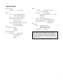
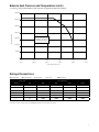
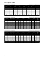
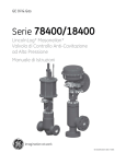
GE Oil & Gas
78400/18400 Series
Masoneilan* LincolnLog*
High Pressure Anti-Cavitation Control Valves
Contents
Features��������������������������������������������������������������������������������������������������3
Valve Sizing Guidelines��������������������������������������������������������������������9
General Data����������������������������������������������������������������������������������������4
Staging Ratios and Pressure Drop Guidelines����������������������9
Numbering System����������������������������������������������������������������������������5
Materials of Construction������������������������������������������������������������10
Temperature Range / Seat Leakage�����������������������������������������5
Soft Seat Design�������������������������������������������������������������������������������21
Balance Seal Pressure and Temperature Limits������������������6
Dimensions�����������������������������������������������������������������������������������������22
Ratings / Connections����������������������������������������������������������������������7
Weights������������������������������������������������������������������������������������������������28
Flow Capacity and FL�����������������������������������������������������������������������7
Accessories and Options�������������������������������������������������������������33
Flow Characteristics��������������������������������������������������������������������������8
Sales Offices�������������������������������������������������������������������� Back Cover
Trim Seat Protection�������������������������������������������������������������������������8
Features
The Masoneilan LincolnLog is the premier high-pressure
liquid letdown valve in the process control industry. It
is a field proven severe service solution for cavitating
and erosive applications in various industries. The
LincolnLog is uniquely designed to operate reliably
in harsh environments and dirty liquids. Key design
features of the LincolnLog include:
Cavitation Elimination
The multi-step flow path created by the LincolnLog trim
design, reduces the pressure drop in multiple stages
without allowing the local pressure to drop below the
fluid vapor pressure thus preventing cavitation. These
active stages throttle in unison to avoid taking the full
pressure drop across any individual stage.
Dirt Tolerant
Wide flow paths in the LincolnLog allow free passage of
large particles through the unique trim and body design
without causing any damage or loss of capacity. This
ensures continuous and efficient operation by
eliminating concerns of potential clogging due to
entrained particles.
The LincolnLog is a proven problem solver in dirty
service applications.
Heavy Plug Guiding
Guiding is provided along the full length of the plug by
a hardened liner, which minimizes any vibration effects
and results in excellent dynamic stability. This helps to
improve product yield through accurate and smooth
process control.
Versatile Trim Options
Standard LincolnLog trim is available in 3, 4 and 6
stages with different staging ratios to cover the vast
majority of high-pressure liquid letdown services.
2
Masoneilan can also provide engineered solutions
consisting of additional stages to satisfy specific application requirements. The LincolnLog is available with
both balanced and unbalanced plug designs for greater
application flexibility.
Protected Seat Design
Overlap is designed into the trim at low lift to keep high
velocity flow away from the valve seat. This helps to
avoid seat erosion and extends the operating life under
high pressure drop conditions.
Reliable Tight Shutoff
Standard seat leakage rating for the LincolnLog meets
IEC 534-4 and ANSI/FCI 70.2 Class V shutoff. An optional
soft seat design provides Class VI bubble tight shutoff.
It includes a patented sliding metal collar design, which
protects the soft seat from extruding and serves as a
back-up seating surface. The LincolnLog can also be
supplied with block valve tight shutoff per MSS-SP-61.
Ease of Maintenance
LincolnLog’s simple top-entry design includes quick
change trim for easy access and removal. The integral
liner and seat ring also reduces the number of components and simplifies assembly and disassembly.
NACE and PED Compliance
The LincolnLog is available for Sour Service Applications
using the design and construction methods defined in
NACE Standard MR0103. Product configurations for applications requiring compliance to MR0175 - 2003 or ISO
15156 are also available upon request. The LincolnLog is
also designed for compliance with Pressure Equipment
Directives (PED) requirements.
General Data
Flow Direction
Standard:Flow-to-open
■■ Body
Type: cast or forged globe style
cast or forged angle style
Sizes: 1” to 8” (DN 25 to DN 200)
Ratings:ANSI Class 600 to 2500 (ISO PN 100 to 420)
API 5000 to 10000
End connections:RFF, RTJ, socket weld,
butt weld, threaded
print flanges (forgings)
■■ Bonnet
Type:Bolted
Standard
Extension
■■ Body and Bonnet
Materials:
carbon steel
316 stainless steel
chrome-moly
others
■■
Trim
Plug type:
multi-step axial flow
(3, 4 and 6 stages)
Seat type:
quick change
integral with plug liner (1” & 1.5” sizes)
metal seat
soft seat
Guide: heavy top guided (liner)
CV ratio:see Flow Capacity tables (page 7)
Flow characteristics:Modified linear
(see page 8)
■■ Actuator
Type:Spring-diaphragm
Spring-return cylinder
Double-acting cylinder
Handwheel:Optional
■■
Optional designs are also available, such as larger sizes,
higher pressure ratings, special materials, or additional
trim stages as required. Consult factory for design details
and specifications.
3
Numbering System
1st
2nd
1st
Body
Series
Actuator Type
1Globe
20 Top Mounted
Manual Handwheel
7Angle
87 Spring-Diaphragm
2nd
3rd
8
4
Trim Type
4 Axial Flow High
Resistance
(Downseating)
4th
No. of
Stages*
3Three
4Four
6Six
Air to Close
5th
6th
Optional
Configuration
Trim Size
0 Optional Trim
FForged
1 Trim A, Balanced
Hard Seat
Body Design
EBExtension
2 Trim B, Balanced
Hard Seat
88Spring-Diaphragm
Air to Open
Bonnet
3 Trim C, Balanced
Hard Seat
84 Cylinder: Spring Return,
Direct, Air
to Close, Single
or Double Acting
(Fail Open Action
4 Trim A, Balanced Soft
Seat
5 Trim B, Balanced Soft
Seat
85 Cylinder: Spring Return,
Reverse
Air to Open, Single
or Double Acting
(Fail to Close)
6 Trim C, Balanced Soft
Seat
7 Trim A, Unbalanced
Hard Seat
86 Cylinder: Double
Acting, Without
Springs, Air to
Open or Air to
Close Action
8 Trim B, Unbalanced
Hard Seat
*Additional stages are available to meet specific operating conditions. Please consult Masoneilan.
9 Trim C, Unbalanced
Hard Seat
Temperature Range / Seat Leakage
Valve Sizes
Temperature Range (1)
inches
DN
1
25
1.5 to 8
40 to 200
2 to 8
50 to 200
Trim Type
Seat Type
Unbalanced
min.
max.(4)
Metal Seat
-20°F (-29°C)
600°F (316°C)
Balanced
Metal Seat
-20°F (-29°C)
600°F (316°C)
Unbalanced
Metal Seat
-20°F (-29°C)
600°F (316°C)
Balanced or
Unbalanced
Soft Seat
-20°F (-29°C)
450°F (232°C)
Seat
Leakage
Class (2)
V
(See Note 3)
VI
1. Designs for higher or lower temperatures are available. Please consult Masoneilan.
2. Seat leakage class ratings per IEC 534-4 and ANSI/FCI 70.2. Class V seat leakage is standard and Class VI is optional.
3. Optional block valve tight shutoff per MSS-SP-61 also available.
4. Max. temp. limit of 600°F (316°C) with unbalanced trim requires use of optional flexible graphite packing or an extension bonnet.
4
Balance Seal Pressure and Temperature Limits
LincolnLog 78400/18400 Balance Seal Pressure-Temperature Application Range
7000 (483)
6000 (414)
5000 (345)
Pressure in psi (bar)
4000 (276)
PTFE (Fluoroloy® A21)
with Elgiloy® Spring and
PTFE Back-up Rings
3000 (207)
2000 (138)
1000 (69)
0
200°F
(93°C)
300°F
(149°C)
400°F
(204°C)
500°F
(260°C)
600°F
(316°C)
700°F
(371°C)
Temperature Range in °F (°C)
Ratings/Connections
q RF Flanged l Socket Weld Valve Size
m Threaded Δ RT Joint n Butt Weld
Pressure Class (2)
(1)
inches
DN
600
900
1500
2500
1 & 1.5
25 & 40
qlmΔn
qlmΔn
qlmΔn
qlmΔn
2
50
qlmΔn
qlmΔn
qlmΔn
qlmΔn
3
80
qΔn
qΔn
qΔn
qΔn
4
100
qΔn
qΔn
qΔn
qΔn
6
150
qΔn
qΔn
qΔn
qΔn
8
200
qΔn
qΔn
qΔn
qΔn
1) Sizes, ratings and end connections are available in both globe and angle body styles.
2) Pressure classes shown represent ASME/ANSI ratings and equivalent PN ratings.
5
Flow Capacity and FL
Satandard Capacity — 3-Stage Design
Valve Size
Inches
Flow Characteristic: MODIFIED LINEAR
Orifice Diameter
DN
Inches
Travel
mm
Inches
mm
CV
Min, Cont. CV
FL
1
25
.70
17.8
.25
6.35
2.0
.98
.05
1.5
40
1.00
25.4
.25
6.35
3.8
.98
.10
2
50
1.50
38.1
.38
9.65
9.0
.98
.15
3
80
2.25
57.2
.62
15.7
20
.98
.25
4
100
2.88
73.2
.75
19.1
34
.98
.43
6
150
4.12
105
1.00
25.4
65
.98
.56
8
200
5.38
137
1.25
31.8
135
.98
1.0
Satandard Capacity — 4-Stage Design
Valve Size
Flow Characteristic: MODIFIED LINEAR
Orifice Diameter
Travel
Trim A
Trim B
Trim C
Min,
Cont.
CV
Inches
DN
Inches
mm
Inches
mm
CV
FL
CV
FL
CV
FL
1
25
.70
17.8
.25
6.35
1.0
.996
1.4
.994
1.7
.991
.04
1.5
40
1.00
25.4
.25
6.35
1.9
.996
2.5
.994
3.2
.991
.08
2
50
1.50
38.1
.38
9.65
4.5
.996
6.0
.994
7.5
.991
.12
3
80
2.25
57.2
.62
15.7
10
.996
13
.994
16.5
.991
.20
4
100
2.88
73.2
.75
19.1
16.5
.996
22
.994
28
.991
.35
6
150
4.12
105
1.00
25.4
34
.996
45
.449
56
.991
.46
8
200
5.38
137
1.25
31.8
70
.996
90
.994
115
.991
.80
Satandard Capacity — 6-Stage Design
Valve Size
6
Trim C
Flow Characteristic: MODIFIED LINEAR
Orifice Diameter
Travel
Trim A
Trim B
Trim C
Inches
DN
Inches
mm
Inches
mm
CV
FL
CV
FL
CV
FL
1
25
.70
17.8
.25
6.35
.80
.996
1.0
.994
1.4
.991
Min,
Cont.
CV
.03
1.5
40
1.00
25.4
.25
6.35
1.4
.996
1.8
.994
2.5
.991
.05
2
50
1.50
38.1
.38
9.65
3.5
.996
4.5
.994
6.0
.991
.08
3
80
2.25
57.2
.62
15.7
7.5
.996
9.5
.994
13
.991
.13
4
100
2.88
73.2
.75
19.1
12
.996
16
.994
22
.991
.22
6
150
4.12
105
1.00
25.4
25
.996
33
.449
45
.991
.30
8
200
5.38
137
1.25
31.8
50
.996
65
.994
91
.991
.65
Flow Characteristics
The LincolnLog trim provides a smooth modified
linear control characteristic with “clearance flow”
capacity over the initial 15% of valve travel as shown
in the generic chart and table at right.
LincolnLog CV vs. Travel
Incorporation of the multi-stage “clearance flow”
design concept prevents high pressure drops across
the LincolnLog seating area while throttling at low
lifts. This feature helps to extend trim life significantly, resulting in dependable and tight shutoff
whenever required. It also improves the throttling
control stability and performance at low lifts, while
providing smooth, accurate and continuous capacity
control from 15% to 100% plug travel. Controllability
extends from the Maximum Rated CV to the
Minimum Controllable CV for any valve size resulting
in typical turndown ratios of 50:1.
% Max. Opening
5
10
20
30
40
50
60
70
80
90
100
% Max. CV
*
*
3
15
27
39
52
64
76
88
100
* Clearance Flow Only
Trim Seat Protection
The “clearance flow” feature described in the previous section is achieved through the trim overlap design
illustrated below:
LincolnLog Trim Overlap Seat Protection Feature
Flow Direction
0 - 15% of Plug Travel
Trim overlap with the valve in the
closed or low lift positions.
Flow Direction
15 - 100% of Plug Travel
There is much greater flow area through
the valve seat versus the plug notches.
As a result, pressure drop and velocities
across the critical seating surfaces are
controlled eliminating seat damage.
7
Valve Sizing Guidelines
General
Trim Selection
LincolnLog multi-stage control valves can be sized
using either standard IEC/ISA equations or using
the latest Masoneilan sizing and selection software
program.
As indicated in the table below, the LincolnLog is
available in various standard trim types and number
of stages. Each trim style provides different staging
ratios and different pressure drop percentages per
stage. Recommended limits for ∆P per stage are 800
psi (60 bar) for continuous duty cycle applications and
up to 1000 psi (70 bar) ∆P per stage for intermittent
service. The recommended operating throttling ∆P
limits are also shown in the table below.
Noise Predictions
Valve noise calculations can be performed using the
Masoneilan sizing and selection program based on the
latest IEC equations. The serial stage construction of
the LincolnLog design helps to
significantly reduce trim noise. Calculating the
noise at the last stage of the LincolnLog trim
will closely approximate the overall valve noise
produced. Pressure drop across the last stage can be
derived from the table below and used in the noise
calculations.
Engineered Solutions
For flashing service, the expansion ratio of the fluid
will determine the appropriate staging ratio to apply.
Non-standard staging ratios can be supplied for
compressible two-phase flow or flashing conditions
not covered by the standard trim. Please consult
Masoneilan for proper sizing and design of engineered
solutions for these types of applications.
Staging Ratios & Pressure
Drop Guidelines
No. of
Stages
Staging
Ratios (1x2)
C
3
1-1-2
C
4
1-1-1-2
Trim Type
B
A
C
B
A
4
4
6
6
6
1-1-2-3
1-1-2-4
1-1-1-1-1-2
1-1-1-1-2-3
1-1-1-1-2-4
Pressure Drop per Stage(3)
Stages
Fraction of
Total ΔP
1 to 2
.44
3
.11
1 to 3
.31
4
.08
1 to 2
.42
3
.11
4
.05
1 to 2
.43
3
.11
4
.03
1 to 5
.19
6
.05
1 to 4
.23
5
.06
6
.025
1 to 4
.23
5
.06
6
.014
Maximum Recommended Throttling ΔP
Continuous Service
Intermittent Service
psi
bar
psi
bar
1595
110
2030
140
2248
155
2900
200
1885
130
2320
160
1885
130
2320
160
3698
255
4713
325
3480
240
4350
300
3408
235
4278
295
(1) Staging ratios provide approximations of the relative area ratios for each specific trim type. As an example, a staging ratio of 1-1-2
indicates that the final stage for that trim type has approximately twice the area of the first two stages.
(2) Staging ratios do not have any relative correlation between the different trim types.
(3) R
ecommended limits for ΔP per stage are 800 psi (60 bar) for continuous duty cycle applications and up to 1000 psi (70 bar) ΔP per
stage for intermittent service.
8
9
Table 4 - TRI-NADO TM Parts List
Item Number
10
Quantity Used
Identification
1
2
Headplate
2
1
Cylinder
3
1
Gearbox
5
1
End Cover
7
2
Impeller
8
4
Bearing Clamp Plate
9
2
Gear
12
1
Shaft - Gear End Driven
14
2
Shaft - Opposite Gear End
16
1
Key (coupling)
17
2
Shim Set
18
2
Gasket - Gearbox/End Cover
21
16
Lock Washer (clamp plates)
22
16
Cap Screw - Hex Head (clamp plates)
23
1
Seal - Drive Shaft
27
4
Seal - Inboard
29
2
Lifting Lug
30
76
Cap Screw - Hex Head (covers/plates)
30A
6
Cap Screw - Hex Head (lifting lugs)
31
4
Bearing - Spherical Roller
34
1
Name
35
18
Drive Screw - Round Head (nameplates/arrow)
36
4
Dowel Pin (gearbox alignment)
37
2
Vent Plug
42
54
Cap Screw - Socket Head (impeller)
43
6
Taper Pin (impeller)
44
1
Label - WHISPAIR™
69
6
Pipe Plug (headplate)
70
5
Pipe Plug gearbox/end cover/cylinder)
74
1
Rotation Arrow
87
2
Sight Plug - Oil Level
92
2
Label - Identification
100
4
Dowel Pin - Pull Out (headplate alignment)
101
2
Lock Nut (gears/bearings)
105
1
Shaft - Gear End Drive
Piston Ring Seal
109
4
141
1
Slinger - Opposite Gear End
181
1
Cover Plate - Cylinder
182
12
Cap Screw - Hex Head (cover plate)
184
1
Slinger - Gear End
185
3
Cap Screw - Button Head (slinger)
Washer (slinger)
186
6
188
2
Washer - Wavy Spring
194
4
Anti-rotation Pin
194A
4
Washer
196
4
Cap Screw - Hex Head (slinger)
197
2
Close Nipple (vent plug)
198
2
Pipe Coupling (vent plug)
203
4
Flat Washer (slinger)
Trouble Shooting Checklist
Trouble
No flow
Low Capacity
Excessive Power
Overheating of bearings
or gears
Vibration
Item
Excessive breather
blowby or
excessive oil leakage to
vent area
Remedy
Speed too low
Check by tachometer and compare with speed on Roots
Order Acknowledgement.
2
3
Wrong rotation
Obstruction in piping
Compare actual rotation, change driver rotation if wrong.
Check piping valve, silencer, to assure open flow path.
4
5
Speed too slow
Excessive pressure rise
6
7
Obstruction in piping
Excessive slip
See Item 1.
Check inlet vacuum and discharge pressure and compare these figures with specified operation conditions on
order.
8
9
10
Speed too high
Excessive pressure rise
Impeller rubbing
See Item 1.
See Item 5.
Inspect outside of cylinder for high temperature areas,
then check
for impeller contact at these points. Look for excessive
scale build-up. Correct blower mounting drive alignment.
11
12
Inadequate lubrication
Excessive lubrication
Check oil sump levels in end covers.
Check oil levels. If correct, drain and refill with clean oil or
recommended grade
13
14
Excessive pressure rise
Coupling misalignment
See Item 5.
Check carefully. Realign if questionable.
15
16
17
Misalignment
Impellers rubbing
Worn bearings/gears
See Item 14.
See Item 10.
Check gear backlash and condition of bearings and
replace as indicated.
18
Unbalanced or rubbing
impellers
Scale or process material may build up on casing and
impellers or inside impellers. Remove build-up to restore
original clearances and impeller balance.
19
20
Driver stops or will not
start
Possible Cause
1
Driver or blower loose
Piping resonance
See Item 3.
Check inside of casing for worn or eroded surfaces causing excessive clearances.
Tighten mounting bolts accurately.
Determine whether standing wave pressure pulsations
are present in the piping. Refer to Sales Office.
21
Impeller stuck
Check for excessive hot spot on headplate or cylinder.
See Item 10. Look for detective shaft, bearing and/or
gear teeth.
22
Broken seal
Replace seals
11
GE Oil & Gas
Roots Blowers, Compressors and Controls
Houston, Texas Headquarters | U.S. Toll Free T 1 877 363 7668 | T +1 832 590 2600
Connersville, Indiana Operations | U.S. Toll Free T 1 877 442 7910 | T +1 765 827 9285
Waukesha, Wisconsin Operations | T +1 262 650 5965 | Email: [email protected]
European Operations | T +44 (0) 1695 52600 | Email: [email protected]
USA/Canada Sales | T +1 773 444 3360
Houston, Texas Factory Service | T +1 713 896 4810
Mexico City Sales and Factory Service | T +52 55 5889 5811
Dubai Sales and Factory Service | T +971 4 8855481
Malaysia Sales | T +60 3 2267 2600
China Sales | T +86 10 8486 2440
Shanghai Factory Service | T +86 21 5858 7638
Visit us online at:
www.geoilandgas.com/valves
2013 General Electric Company
All Rights Reserved
*Denotes trademarks of General Electric Company
GEA19511 ILRB_3007
04/2013