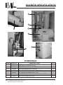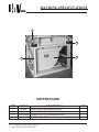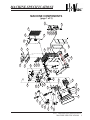
1
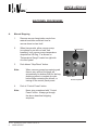
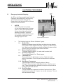
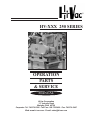
HV-XXX 250 SERIES
OPERATION
PARTS
& SERVICE
MANUAL
Hi-Vac Corporation
117 Industry Road
Marietta, Ohio 45750
Corporate: Tel: 740.374.2306 - Toll Free: 800.752.2400 - Fax: 740.374.5447
Web: www.hi-vac.com - E-mail: [email protected]
TABLE OF CONTENTS
INSPECTION OF YOUR NEW Hi-Vac® UNIT
WARRANTY INFORMATION FOR YOUR NEW Hi-Vac® UNIT
MESSAGE TO NEW OWNER
SECTION 1 : SAFETY PRECAUTIONS
GENERAL PRECAUTIONS AND WARNINGS
PLEASE READ!!
SAFETY FIRST!!
SECTION 2 : MACHINE SPECIFICATIONS
BASIC DESCRIPTION OF A Hi-Vac® UNIT
THEORY OF OPERATION
POWERHEAD
HOPPER/STAND/TRAILER
MACHINE COMPONENTS
SHAKER ASSEMBLY
SEAL ASSEMBLY
FILTER BAG ASSEMBLY
RECOMMENDED SPARE PARTS LIST
SECTION 3 : OPTIONS
AS LISTED
SECTION 4 : INSTALLATION
SET-UP PROCEDURES
SECTION 5 : OPERATIONS
PRESTART PROCEDURES
START-UP PROCEDURES
SHUTDOWN PROCEDURES
AUTOMATIC PROTECTION SYSTEMS
HEPA FILTER OPTION
CONVEYING TIPS AND NOZZLE USAGE
Hi-VAC® OPERATIONS, PARTS, & SERVICE MANUAL
2
SECTION 6 : MAINTENANCE
BAG CHANGE PROCEDURES
DUST PASSAGE FILTER CHANGING PROCEDURES
TENSIONING V-BELT DRIVES
ADJUSTING OIL LEVEL SWITCH
ADJUSTING THE SENSITIVITY OF THE LEVEL PROBE
MAINTENANCE INSTRUCTIONS
RECOMMENDED LUBRICANTS
LUBRICATION MAINTENANCE RECORD
BILL OF MATERIALS
SECTION 7 : PREVENTIVE MAINTENANCE
DAILY CHECKS
WEEKLY CHECKS
MONTHLY CHECKS
RECORDS
TROUBLESHOOTING
SECTION 8 : ELECTRICAL
CONTROL PANEL SCHEMATIC
SECTION 9 : ACCESSORIES
ACCESSORIES
SECTION 10 : MANUFACTURERS MANUALS
ROOTS BLOWER MANUAL
ENIDINE AIR BAGS
DREXELBROOK LEVEL PROBE
KUNKLE RELIEF VALVE
LEESON ELECTRIC MOTORS
FLANDERS HEPA FILTER
GROVE GEAR REDUCER
A/B MICRO 1000 (located on CD only)
BARKSDALE VALVE DWYER INSTRUMENTS GEMS LEVEL SWITCH UNITED ELECTRIC CONTROLS
Hi-VAC® OPERATIONS, PARTS, & SERVICE MANUAL
3
INSPECTION PROCEDURES
All pieces received should be inspected for damage immediately upon receipt.
1.
Damage can be most easily detected by looking for scrapes on the paint.
2.
3.
4.
Inspect all sheet metal and structural steel for damage such as bends, kinks or breaks.
5.
Check motor and vacuum pump for free rotation before starting under power for the first time after installation.
6.
Compare the packing list attached to each piece of each shipment.
7.
Verify the number of pieces and description of each piece shown on the packing slip.
Check all wiring for abrasions, cuts, cracks, etc. If any are found, repair or replace before connecting to power source.
Check all conduit runs and fittings for defects.
REPORT ANY DAMAGE, NO MATTER HOW SLIGHT, IMMEDIATELY TO:
Hi-Vac® Corporation
117 Industry Road
Marietta, OH 45750
Attention: Service Department
Phone: 740.374.2306
Toll Free: 800.752.2400
Fax: 740.374.5447
Storage of your Hi-Vac® unit
Allow machine to be crated if at all possible while storing for short or long term durations.
1. For short-term storage. (30 days or less)
A.
2.
For storage over 30 days
Rotate shafts every two to three weeks to avoid flat spotting of the ball bearings.
A.
To prevent damage due to corrosion, oxidation, etc., Refer to the maintenance manuals for each component.
B.
Make sure that the inlets to the piping manifold system are covered with the dust plugs to prevent foreign objects from entering the system.
Add packages of desiccant to all electrical enclosures on sides of Hi-Vac®.
C.
D.
Turn off the compressed air supply to the Hi-Vac® and relieve any pressure in the compressed air lines on the unit.
Hi-VAC® OPERATIONS, PARTS, & SERVICE MANUAL
4
WARRANTY
Hi-Vac® CORPORATION WARRANTS TO THE ORIGINAL PURCHASER OF THE Hi-Vac® UNIT
QUOTED HEREIN THAT THE Hi-Vac® UNIT SHALL BE FREE FROM DEFECTS IN MATERIAL AND
WORKMANSHIP UNDER NORMAL USE AND SERVICE. Hi-Vac® CORPORATION DOES NOT
WARRANT COMMERCIAL ITEMS MANUFACTURED BY OTHERS SUCH AS DIESEL ENGINES,
TRUCK CHASSIS, TIRES OR MOTORS. Hi-Vac® CORPORATION’S OBLIGATION UNDER THIS
WARRANTY SHALL BE LIMITED TO THE REPAIR OR EXCHANGE OF ANY PART OR PARTS
WHICH MAY PROVE DEFECTIVE UNDER NORMAL USE AND SERVICE WITHIN THE SHORTER
PERIOD OF TWO (2) YEARS OR FOUR THOUSAND (4,000) WORK HOURS FROM THE DATE
OF DELIVERY TO THE ORIGINAL PURCHASER AND WHICH Hi-Vac® CORPORATION’S EXAMINATION SHALL DISCLOSE TO ITS SATISFACTION TO BE DEFECTIVE. THIS WARRANTY
REQUIRES PURCHASER TO OPERATE THE Hi-Vac® UNIT IN STRICT COMPLIANCE WITH THE
PRINTED INSTRUCTIONS AND TO SERVICE THE Hi-Vac® UNIT ACCORDING TO THE METHODS
AND SCHEDULES CONTAINED IN THE Hi-Vac® UNIT’S MANUAL. EVIDENCE OF PURCHASER’S
SCHEDULED MAINTENANCE MUST BE REPORTED IN WRITING TO Hi-Vac® CORPORATION ON
THE FORMS SUPPLIED TO PURCHASER IN THE Hi-Vac® MAINTENANCE MANUAL. SHOULD
PURCHASER BELIEVE A DEFECT HAS BEEN DISCOVERED, THE PURCHASER SHALL RETURN
THE ALLEGED DEFECTIVE PART TO Hi-Vac® CORPORATION FOR EXAMINATION, F.O.B THE
Hi-Vac® PLANT, MARIETTA, OHIO. IN THE EVENT PURCHASER DOES NOT SERVICE AND
MAINTAIN THE Hi-Vac® UNIT ACCORDING TO THE Hi-Vac® MAINTENANCE MANUAL, THE WARRANTY IS TO BE CONSIDERED NULL AND VOID AND Hi-Vac® CORPORATION’S OBLIGATION HEREUNDER SHALL BE DEEMED FULFILLED.
THIS WARRANTY IS EXPRESSLY IN LIEU OF ALL OTHER WARRANTIES EXPRESSED OR
IMPLIED, INCLUDING THE WARRANTIES OF MERCHANTABILITY AND FITNESS FOR USE AND
OTHER OBLIGATIONS OR LIABILITIES ON THE PART OF Hi-Vac® CORPORATION.
LIMITS OF LIABILITY
Hi-Vac® CORPORATION SHALL NOT BE LIABLE FOR AND PURCHASER ASSUMES RESPONSIBILITY FOR ALL PERSONAL INJURY AND PROPERTY DAMAGE RESULTING FROM
THE HANDLING, POSSESSION OR USE OF YOUR Hi-Vac® INDUSTRIAL VACUUM CLEANER BY
THE PURCHASER. THE LIABILITY OF Hi-Vac® CORPORATION ARISING OUT OF THE SUPPLYING OF YOUR Hi-Vac® INDUSTRIAL VACUUM CLEANER, OR ITS USE WHETHER
ON WARRANTIES OR CLAIM OF NEGLIGENCE OR OTHERWISE, SHALL NOT IN ANY CASE
EXCEED THE COST OF CORRECTING DEFECTS IN YOUR Hi-Vac® INDUSTRIAL VACUUM
CLEANER AS HEREIN PROVIDED. Hi-Vac® CORPORATION SHALL NOT IN ANY EVENT BE
LIABLE FOR ANY LABOR EXPENDED BY THE PURCHASER ON ANY PART OR PARTS OR FOR
ANY SPECIAL DIRECT OR INDIRECT OR CONSEQUENTIAL DAMAGES. NO MATERIAL MAY
BE RETURNED WITHOUT FIRST GETTING APPROVAL FROM Hi-Vac® CORPORATION. ANY
GOODS RETURNED WITH SUCH APPROVAL MUST BE SENT BACK WITH ALL TRANSPORTATION CHARGES PREPAID WITHIN 30 DAYS AFTER ISSUANCE OF APPROVAL.
GOODS RETURNED AND ACCEPTED IN ACCORDANCE WITH THE ABOVE CONDITIONS WILL
BE CREDITED ON THE BASIS OF THE PRICES PAID AT TIME OF SHIPMENT.
Hi-VAC® OPERATIONS, PARTS, & SERVICE MANUAL
5
MESSAGE TO NEW OWNER
Congratulations on your purchase of a new Hi-Vac® INDUSTRIAL VACUUM
SYSTEM. Hi-Vac® Corporation is a leader in conveying and material pickup. The
use of a Hi-Vac® system will not only save you money in the short term, it will
also put you on the cutting edge of todays
technology in vacuum systems. With HiVac’s vast array of configurations, it is
possible to meet every consumers needs in material pickup for both wet and dry
applications.
To get the most out of your new Hi-Vac® INDUSTRIAL VACUUM
SYSTEM , please read and review the contents of this manual and become familiar with the procedures within.
Thank you for your purchase and we look forward to serving you again in
the future.
Hi-VAC® OPERATIONS, PARTS, & SERVICE MANUAL
6
SAFETY
PRECAUTIONS
SAFETY PRECAUTIONS
CAUTION!
SOME DO’S AND DON’TS BEFORE GETTING STARTED WITH YOUR
NEW Hi-Vac® SYSTEM.
The safety of the operator is of great importance to us at Hi-Vac® Corporation. The decals, shields,
guards and other protective features that are designed into the machine are there for your protection.
A high percentage of the accidents that occur are due to careless behavior or misuse of machinery.
We ask you to be a careful operator and to properly service your machine.
AIRLIFT SAFETY NOTE: Airlifts are standard on all units with an end dump hopper.
Before startup, remove the three (3) powerhead shipping spacers and discard. This is done by
unscrewing the pipe caps, slipping off the spacers, and reinstalling the three (3) caps on the pipe.
BE SURE TO REINSTALL THE CAPS BACK ONTO THE PIPE. FAILURE TO DO SO MAY CAUSE
SERIOUS INJURY TO PERSONNEL AND/OR DAMAGE TO MACHINE.
Hi-VAC® OPERATIONS, PARTS, & SERVICE MANUAL
SAFETY PRECAUTIONS
1
SAFETY PRECAUTIONS
PROCEED WITH CAUTION!
Before attempting to operate the machine, read carefully and understand all instructions contained in the
manual.
*
Do not put your hand in front of the intake nozzle while in operation.
*
Do not put your face or any portion of head in front of the nozzle.
*
Do not open control panel or remove any junction box cover while main power supply is live.
*
Do not vacuum any flammable liquid.
*
For mobile configurations, check that unit is properly stopped so unit will not tip or roll.
*
Do not lubricate, adjust or repair the Hi-Vac® unit unless power source to the electric motor has been disengaged, and locked out.
*
Keep all safety devices in place, while operating your Hi-Vac® unit.
*
Read all warning and instruction decals placed on the machine and its associated equipment.
*
Allow only responsible, properly instructed individuals to operate the machine.
*
Always keep the Hi-Vac® unit in good operating condition.
*
*
Clear the work area of objects that might interfere with proper operation of the Hi-Vac® unit.
*
Do not operate the Hi-Vac® unit while wearing loose clothing, watches or rings.
*
Periodically check for any loose bolts or set screws.
Be careful to avoid overhead electrical installations. Extreme caution should be
exercised whenever working near or around electrical installations.
NOTE:
AS WITH ANY TYPE OF HEAVY DUTY EQUIPMENT, CAUTION MUST BE EXERCISED IN ITS PROPER USE.
CAUTION:
KEEP HANDS CLEAR AND AWAY FROM BETWEEN POWERHEAD AND HOPPER WHEN POWERHEAD IS RAISED AND WHEN LOWERING POWERHEAD
WARNING:
FAILURE TO COMPLY WITH ANY OF THE ABOVE SAFETY INSTRUCTIONS OR THOSE THAT FOLLOW WITHIN THIS MANUAL MAY RESULT IN SEVERE INJURY OR DEATH!
PLEASE REMEMBER:
Safe operation begins with a safe operator. We ask you to be that type of operator.
Hi-VAC® OPERATIONS, PARTS, & SERVICE MANUAL
2
SAFETY PRECAUTIONS
MACHINE
SPECIFICATIONS
MACHINE SPECIFICATIONS
BASIC DESCRIPTION OF A 200 SERIES Hi-Vac® UNIT.
The MODEL NUMBER is broken down into three descriptive parts.
1.
The first part is the SHELL SERIES. This describes the series of the Hi-Vac® unit. Both the LC and HC have twelve (12) filter bags.
2.
The second part is the HORSEPOWER given to the POWERHEAD. There are six different ranges of motors on a 200 SERIES Hi-Vac®. 20HP, 25HP, 30HP, 40HP, 50HP, AND 75HP.
3.
The third part is the clearance factor of the SHELL. The 200 SERIES Hi-Vac® has two different clearances depending on the application for which it is use. That being (HC) High Clearance or (LC) Low
Clearance. The (LC) designation is always tagged onto the end of the model number. The (HC) designation is almost always assumed and usually left off.
Hi-VAC® OPERATIONS, PARTS, & SERVICE MANUAL
MACHINE SPECIFICATIONS
1
MACHINE SPECIFICATIONS
THEORY OF OPERATIONS
A SIMPLE NARRATIVE OF HOW A Hi-Vac® WORKS
The following pages will describe, in as much detail as practical, the Hi-Vac® vacuum system. The system
consists of four major components. The Hi-Vac® Powerhead, which is the actual vacuum producing part of the
system, is mounted on a hopper. The Powerhead and hopper are mounted in a support stand. Connected to
the Powerhead/hopper/support stand assembly is a pipe (hose), used to direct vacuum (air flow to material to
be conveyed).
The intent of the system is to pick up spills and dust accumulations through various parts of the Hi-Vac® and
return the materials to the to the plant. By carefully reading and following the instructions contained herein,
the equipment will operate reliably and the plant environment will be improved, thereby making it a safer and
cleaner place to work.
The Hi-Vac®, in it’s simplest form, is a large vacuum cleaner. A positive displacement pump is used to evacuate
the air from the storage bin below the Hi-Vac® Powerhead. Because there is a vacuum in the hopper, air enters
it through the pick-up hose and piping connected to the unit. It is this air movement that conveys the material
from the pick-up point to the Hi-Vac®.
The heart of the system is a positive displacement lobe vacuum pump (blower). It is driven by a coupler or a
set of v-belts and sheaves connected to a drive element, which could be an electric motor or a fuel fed engine.
The blower contains impeller lobes spinning in opposite directions and always in contact of each other and the
blower housing. While spinning, the lobes are capturing small volumes of air and pushing them out of the blower
discharge and through an exhaust silencer back into the atmosphere.
In order to prevent the material (and the dust generated by this conveying procedure) from being discharged into
the atmosphere as well, a set of filter cartridges are installed. Before the air and material go into the blower they
must first pass through these cartridges which remove nearly 100% of the dust from the air. As well as protecting
the atmosphere from dust, this also stops any dust from entering the blower and causing serious damage.
There is one stage of separation of the material and dust from the air before they get to the filter cartridges. As
the material enters the Hi-Vac® from the pickup hose and piping system it goes through a centrifugal separator
which spins the material out of the air stream and into the collection bin below the Powerhead. Any material left
in the air is then carried to the filter bags.
As the air passes through the filter cartridges, the dust is trapped on the outside of the cartridges. Every 10 to
15 seconds, compressed air is blasted into the inside of the cartridges. This pulse of air keeps the outside of
the cartridges clean.
There are several different types of material bins, all of which will eventually fill with material. When this
occurs, the unit will shut down and cannot be restarted until this condition is corrected. In some cases, as with
end dump and rear dump hoppers, the Powerhead will be lifted off of the hopper with an airlift. The hopper
will then be taken by a fork lift to a location to be emptied then replaced below the Powerhead. In this case
the Powerhead must be restarted manually. In other cases, as with bottom dump hoppers, it may have a self
dumping discharge gate. In this situation, the unit will shut down momentarily, discharge the material, the gate
will close, and the unit will restart automatically (there is a switch in the panel to override this auto-restart). This
self dumping gate may be replaced with any one of several optional discharges. Any thing from rotary feeders
and pinch valves (for continuous discharge) to knife gates and fluid powered swing gates (for regulated and/or
remote applications).
Hi-VAC® OPERATIONS, PARTS, & SERVICE MANUAL
2
MACHINE SPECIFICATIONS
MACHINE SPECIFICATIONS
3
4
6
1
5
2
7
POWERHEAD
ITEM
1
2
PART #
DESCRIPTION
09-0002-MFD SILENCER,5”,STANDARD HI-VAC
20-0216
HEPA FILTER,24x24x11-1/2,SS,HT,HI-CAP. (Inside Plenum)
1
1
3
4
16-0006
03-0392
VALVE,VACUUM RELIEF,3”,(18”HG)
BLOWER,ROOTS,412 RAMJ,WHISPAIR,RH,BD
1
1
5
04-0003
MOTOR,50HP,230/460/3/60,326T,TEFC
1
6
27-0181
DREXELBROOK POINT-LINE LEVEL PROBE SYSTEM
1
7
27-0012
SWITCH,OIL LEVEL,SPST N/O
2
Hi-VAC® OPERATIONS, PARTS, & SERVICE MANUAL
3
QTY
MACHINE SPECIFICATIONS
MACHINE SPECIFICATIONS
1
2
4
3
HOPPER/STAND
ITEM
PART #
1
2
3
15-0001
VALVE,4-WAY,1/4NPT,MANUAL,AIR LIFT
15-0066
BAG,AIR LIFT,DOUBLE CONVOLUTE
31-2022-MFD STAND,A/L,2CU.YD.,200/400/800 SERIES
4
30-1005-MFD HOPPER,END,1.5YD
Hi-VAC® OPERATIONS, PARTS, & SERVICE MANUAL
4
DESCRIPTION
MACHINE SPECIFICATIONS
QTY
1
4
1
1
510
512
506
523
519
502
517
513
521
516
518
508
515
514
505
520
522
303
305
304
509
301
501
527
526
521
701
507
525
504
503
302
103
105
601
602
103
102
704-10
704-11
101
103
104
201
204
703
702-2
702-3
702-4
702-1
206
207
202
703
704-1
MACHINE SPECIFICATIONS
MACHINE COMPONENTS
(page 1 of 3)
Hi-VAC® OPERATIONS, PARTS, & SERVICE MANUAL
MACHINE SPECIFICATIONS
5
MACHINE SPECIFICATIONS
MACHINE COMPONENTS
(page 2 of 3)
ITEM
PART #
DESCRIPTION
101
102
01-2203-MFD SHELL WELDMENT,200 SERIES HIGH CLEARANCE
01-2209-MFD DOOR,SIDE BAGHOUSE,200 SERIES
103
104
18-0188
GASKET,RUBBER UTILITY,1/4” X 3/4” X 50’
01-2208-MFD DOOR,TOP BAGHOUSE,200 SERIES
1
1
105
01-2212-MFD DOOR,LINEAR SEPARATOR,200/400 SERIES
1
1
1
201
20-0027
FILTER BAG,HC,POLYESTER FELT
12
202
19-0008
CAGE,FILTER BAG,HIGH CLEARANCE UNITS
12
204
206
207
01-1386-MFD BAR,RETAINER,END,HI-VAC BAGS,200 SERIES
08-0007
PIN,COTTER,1/8” X 1”,PLTD,HAMMERLOCK
01-1387-MFD BAR,RETAINER,MIDDLE,HI-VAC BAGS,200 SERIES
2
4
7
301
04-0003
MOTOR,50HP,230/460/3/60,326T,TEFC
1
302
04-0068
MOTOR SLIDE BASE,326T FRAME
1
303
01-2927-MFD ISOLATOR BASE,200/400 SERIES
1
304
18-0260
ISOLATOR,SMALL
8
305
18-0209
ISOLATOR,MEDIUM
8
501
03-0392
BLOWER,ROOTS,412 RAMJ,WHISPAIR,RH,BD
1
502
09-0002-MFD SILENCER,5”,STANDARD HI-VAC
1
503
11-0185-MFD NOZZLE,LINEAR SEPARATOR,50HP
1
504
11-0189-MFD ORIFICE PLATE,50HP
1
505
02-3497-MFD INLET PIPING,R412,200 SERIES
1
506
02-0147-MFD DISCHARGE PIPING,R412-J,200/400 SERIES
1
507
12-0030-MFD BROKEN BAG DET,240/250HC,608
1
508
509
09-0007
RAINCAP,5.25”,ALUM,#18
01-5173-MFD BLOWER BASE,R412,250 HIVAC
Hi-VAC® OPERATIONS, PARTS, & SERVICE MANUAL
6
QTY
MACHINE SPECIFICATIONS
1
1
MACHINE SPECIFICATIONS
MACHINE COMPONENTS
(page 3 of 3)
ITEM
PART #
DESCRIPTION
LUBE LEVEL SWITCH ASSY,R-409,412,418
VALVE,VACUUM RELIEF,3”,(18”HG)
MUFFLER ISOLATION BRACKET,200HC/400HC
QTY
510
512
513
27-0026-MFD
16-0006
09-0054-MFD
1
1
1
514
06-0153
SHEAVE,5V15.0 X 4-E
1
515
06-0132
BUSHING,E X 2.125
1
516
06-0137
SHEAVE,5V7.1 X 4-SF
1
517
U3403-0017
BUSHING,SF X 1.5 W/ 3/8 KW QD SERIES
1
518
07-0007
BELT,5VX1060
3
519
520
01-1888-MFD
01-5174-MFD
FLANGE,MUFFLER,5”,200/400 SERIES
BELT GUARD BACK,250HC,R412
1
1
521
01-5175-MFD
BELT GUARD COVER,250HC,R412
1
522
01-5176L-MFD BRACKET,LEFT,BELTGUARD,250HC,R412
1
523
18-0146
GASKET,FLANGE,5”,FOR USE W/5”DIA EXHAUST
2
525
18-0003
GASKET,1/4” X 2” X 50’ ROLL
526
18-0423
SLEEVE,FLEXIBLE,6”ID X 4-PLY X 6” LONG
2
527
10-0575
CLAMP,T-BOLT,6-1/4” - 6-9/16”,HEADR SLVE
2
601
18-0042
GASKET,INLET
1
602
01-0875-MFD
INLET ADAPTER,5”,200 SERIES
1
701
27-0181
DREXELBROOK POINT-LINE LEVEL PROBE SYSTM
1
702-1
16-0011
GAUGE,VACUUM,0-30”,5 1/4 DIA FACE
1
702-2
02-0256
ELBOW,PIPE,90D,1/4”FNPT,150#,MI
1
702-3
02-0048
ADAPTER,STR,1/4”MNPT X 1/4” HOSE BARB
2
702-4
10-0041
HOSE,FUEL LINE,PUSH-LOC,1/4”
8
704
12-0046
INSTALLATION,MAGNEHELIC(PRESS.DIFF)GAUGE
1
.0700
Hi-VAC® OPERATIONS, PARTS, & SERVICE MANUAL
MACHINE SPECIFICATIONS
7
MACHINE SPECIFICATIONS
SHAKER ASSEMBLY (page 1 of 2)
203-4
203-5
203-6
203-1
203-2
112
203-6
403
110
203-3
103
402
413
407
415
406
414
416
408
404
314
405
ITEM
103
110
112
203-1
PART #
DESCRIPTION
GASKET,RUBBER UTILITY,1/4” X 3/4” X 50’
01-2211-MFD DOOR,SHAKER COVER,200 SERIES
18-0188
01-2525-MFD RAINSHIELD,SHAKER MOTOR,200/300/400
01-1923-MFD BAR,TIE,200 SERIES
203-2
18-0292
203-3
A107216
203-4
A107062
203-5
21-0905
203-6
A107214
314
04-0102
BUMPER,RECESS
SCREW,CAP,5/16-18 X 1”,HH,PLT,GR8
NUT,HEX,5/16”-18,GR8,PLATED
LOCK WASHER,RCS BUMPER*NO LONGER USED
WASHER,FLAT,5/16” SAE,PLATED,GR8
MOTOR,3/4HP,230/460/3/60,56C,TEFC
Hi-VAC® OPERATIONS, PARTS, & SERVICE MANUAL
8
401
MACHINE SPECIFICATIONS
QTY
1
1
1
1
1
1
1
2
1
1
MACHINE SPECIFICATIONS
SHAKER ASSEMBLY (page 2 of 2)
ITEM
PART #
DESCRIPTION
QTY
401
01-1168-MFD MOUNT,SHAKER GEAR,200/300/400 SERIES
402
01-2514-MFD SHAKER SHAFT,200 SERIES
1
403
01-2515-MFD DRIVE BAR,SHAKER,200 SERIES
24-0059
BAG SHAKER,ECCENTRIC
1
404
405
25-0013
406
17-0010
407
08-0009
408
21-2405
413
08-0068
414
08-0136
415
18-0056
GEAR REDUCER,SHAKER
BEARING,3/8” ROD END
YOKE END,3/8”-24,W/CLEVIS PIN & COTTER
SCREW,SET,5/16”-18 X 3/4”,SOCKET
PIN,CLEVIS,1/2” DIA. X 2” LONG
PIN,COTTER,1/8” X 2”
GASKET,RUBBER DIAPHRAGM
1
1
1
1
1
2
1
1
1
Hi-VAC® OPERATIONS, PARTS, & SERVICE MANUAL
MACHINE SPECIFICATIONS
9
MACHINE SPECIFICATIONS
SEAL ASSEMBLY
606
605
607
101-31
101-31
109
108
107
106
ITEM
PART #
101-32
18-0026
106
18-0041
107
01-0873-MFD
108
18-0040
109
01-0869-MFD
605
01-2223-MFD
606
01-2224-MFD
607
01-2225-MFD
101-31
18-0027
DESCRIPTION
GASKET,SHORT,1”x6”x45 1/4”LG.NEOPRENE
GASKET,LONG,1”x6”x61 1/2”LG.NEOPRENE
SEAL,FLAP,BAGHOUSE
BAR,RETAINER,BAGHOUSE FLAPSEAL
SEAL,FLAP,LINEAR SEPARATOR
BAR,RETAINER,LINEAR SEPERATOR FLAPSEAL
CENTRIFUGAL RING,200 SERIES,STD
INLET PIPE,200 SERIES
STACK EXTENSION,200 SERIES
Hi-VAC® OPERATIONS, PARTS, & SERVICE MANUAL
10
MACHINE SPECIFICATIONS
QTY
2
2
1
1
1
1
1
1
1
MACHINE SPECIFICATIONS
FILTER BAG ASSEMBLY
207
204
204
210 211 212
213 214 208
213 214 208
201
202
203
209
209
205
ITEM
201
202
203
204
PART #
20-0027
19-0008
206
DESCRIPTION
FILTER BAG,HC,POLYESTER FELT
CAGE,FILTER BAG,HIGH CLEARANCE UNITS
20-0076-MFD KNOCKER BAR ASSY,200HC,12 BAG
01-1386-MFD BAR,RETAINER,END,HI-VAC BAGS,200 SERIES
QTY
12
12
1
2
205
21-1106
WASHER,FLAT,3/8” NOM,GR5,PLATED
4
206
08-0007
PIN,COTTER,1/8” X 1”,PLTD,HAMMERLOCK
4
207
01-1387-MFD BAR,RETAINER,MIDDLE,HI-VAC BAGS,200 SERIES
7
208
21-1406
BOLT,3/8”-16 HEX x 2-1/2”LG, GR 5, PLATE
38
209
18-0126
GROMMET,5/16”I.D.
36
210
21-1404
BOLT,1/4”-20 HEX
14
211
A107214
WASHER,FLAT,5/16” SAE,PLATED,GR8
14
212
21-0904
WASHER,LOCK,1/4”NOM,GR8,PLATED
14
213
21-1106
WASHER,FLAT,3/8” NOM,GR5,PLATED
38
214
A107294
WASHER,LOCK,3/8”,PLT,GR8
38
Hi-VAC® OPERATIONS, PARTS, & SERVICE MANUAL
MACHINE SPECIFICATIONS
11
MACHINE SPECIFICATIONS
RECOMMENDED SPARE PARTS LIST
ITEM
PART #
20-0027
19-0008
FILTER BAG,HC,POLYESTER FELT
CAGE,FILTER BAG,HIGH CLEARANCE UNITS
2
18-0040
SEAL,FLAP,LINEAR SEPARATOR
1
3
4
18-0041
16-0011
SEAL,FLAP,BAGHOUSE
GAUGE,VACUUM,0-30”,5 1/4 DIA FACE
1
1
5
16-0012
GAUGE,DIFF PRESSURE,0-20”,4 3/4 DIA FACE
1
6
13-0001
SWITCH,PRESS. DIFF,SPDT,3-22”WC
1
7
20-0069
FILTER TUBE,PRESSURE DIFFERENTIAL
4
8
18-0188
GASKET,RUBBER UTILITY,1/4” X 3/4” X 50’
1
9
20-0073
FILTER ELEMENT,FOR BROKEN BAG DETECTOR
3
10
17-0010
BEARING,3/8” ROD END
1
11
24-0059
BAG SHAKER,ECCENTRIC
1
12
08-0009
YOKE END,3/8”-24,W/CLEVIS PIN & COTTER
1
13
18-0056
GASKET,RUBBER DIAPHRAGM
2
14
20-0216
HEPA FILTER,24x24x11-1/2,SS,HT,HI-CAP.
1
1
2
DESCRIPTION
Hi-VAC® OPERATIONS, PARTS, & SERVICE MANUAL
12
MACHINE SPECIFICATIONS
QTY
12
12
OPTIONS
OPTION 110
END DUMP RESTART
OPTION 440
STARTER,1/4HP MOTOR
OPTION 621
HEPA FILTER DIFFERENTIAL SHUTDOWN
INSTALLATION
INSTALLATION
SET-UP PROCEDURES
After you have done all the inspection
procedures as recommended in the beginning
of this manual, you are now ready to install your
Hi-Vac® unit. Please follow the procedures
listed in this section. If you have any
questions, please feel free to call Hi-Vac® at
1.800.752.2400 or in OHIO call 1.740.374.2306.
Your Hi-Vac® unit is broken down into
4 sections. Hopper, Stand, Airlift, and
Powerhead. Once together, you can move the
unit throughout the plant using the optional 4
wheeled In-Plant trailer. Be sure that the Airlift
is bolted to the stand before operation begins.
A
C
B
Note: When moving the Powerhead and/or Hopper, always lift from the fork openings.
Note: Refer to your electrical schematic for proper voltage specification.
Note: Use National or Local electrical codes to install incoming power to your Hi-Vac® unit.
1.
Connect customer supplied power cord as shown in item A. This must be done by a certified electrician.
2.
Connect Airline to unit as shown in item B. The minimum required air pressure is 1 CFM at 90 PSI.
Caution: Maximum air pressure should not exceed 120psi.
3.
Remove the three (3) spacers on powerhead guides. Be sure to replace caps on guides and tighten down firmly. See item C.
4.
You are now ready for the Pre-start procedures for your new Hi-Vac® unit.
Hi-VAC® OPERATIONS, PARTS, & SERVICE MANUAL
INSTALLATION
1
OPERATIONS
OPERATIONS
PRESTART PROCEDURES
Note: As with any type of heavy duty equipment, caution must be exercised in
its proper use. A thorough understanding of the use and functions of this equipment should be attained before an attempt is made to use it.
1.
Connect or disconnect vacuum conveying hoses and fittings to the machine inlet pipe or manifold system only when the powerhead is off.
Note: FAILURE TO DO SO COULD RESULT IN INJURY TO OPERATING PERSONNEL.
2.
Before starting the machine, check all fluid levels. This includes the vacuum pump oil levels (Rear on all units and shaft end if so equipped). Level should be midway on site glass.
TYPES OF OIL SITE GLASSES
3.
Before starting the machine, check all wiring for abrasions, cuts, cracks, etc. If any, repair or replace.
Note: BE SURE TO DISCONNECT ALL POWER WHEN REPAIRING
ELECTRICAL LINES. FAILURE TO DO SO COULD RESULT IN INJURY.
4.
Before starting the machine, check all conduit runs and fittings for defects.
Hi-VAC® OPERATIONS, PARTS, & SERVICE MANUAL
OPERATIONS
1
OPERATIONS
PRESTART PROCEDURES
Control Power
5.
Check electric blower motor for proper rotation as follows:
1.
Pull the “Control Power” switch to the on position.
2.
Place hand under HEPA Filter plenum.
3.
“Bump” electric motor by pushing the “Blower Start” button and immediately push the “Blower Stop/Reset” button.
Blower Start
Blower Stop/Reset
I.
If air is exhausted from the plenum, the rotation is correct.
II.
If air is pulled into the plenum, the rotation is wrong.
a.
Correct this by first insuring that incoming power is disconnected, then rewire incoming service wire at the top of the circuit breaker.
Note: This will correct both the blower motor as well as the bag shaker motor. DO NOT REVERSE ANY WIRES BELOW THE CIRCUIT BREAKER.
6.
HEPA Filter Plenum
Check bag shaker timer setting as follows:
A.
Initiate a bag shaking cycle by “bumping” the blower motor as stated for the motor rotation.
B.
Note:
Verify that the shaker motor runs for at least 30
seconds. If not, adjust timer located inside main
electrical control panel under the programmable controller.
Additional shaking time is required to higher dust loads. Maximum shaking time is 60 seconds.
Bag Shaker Motor
Hi-VAC® OPERATIONS, PARTS, & SERVICE MANUAL
2
OPERATIONS
OPERATIONS
START-UP PROCEDURES
A.
Electric Motor Drive
1.
2.
Perform pre-start procedures
Confirm that vacuum conveying hoses and fittings are connected and pick up nozzle is out of material so that the vacuum pump may “breathe freely” during startup.
Note:
Always connect or disconnect vacuum conveying hoses and nozzles to your Hi-Vac® inlet or manifold before turning on the powerhead.
FAILURE TO DO SO COULD RESULT IN INJURY TO OPERATING PERSONNEL.
3.
Control panel door must be closed and locked.
4.
Circuit breaker turned on.
5.
“Control Power” turned on by pulling out on button.
6.
Push blower “Stop/Reset” button.
7.
Push blower “Start” button.
Note:
Note:
For units supplied with the new Drexelbrook “The Point Series” Level Probe:
During initial start-up and after a loss of power, the operator must wait approx. 20 seconds to allow the probe to finish its calibration cycle. The blower will not start and the “Hopper Full” light will remain on until the cycle is complete and the blower “Stop/Reset” button is pushed.
Control Power
Blower Start
Blower Stop/Reset
The blower is turning in the correct rotation if the silencer exhaust cover lifts open and air is discharging from the silencer.
8.
Your Hi-Vac® is now operating and ready to use.
Check your gauges to make sure tha the unit is
running correctly.
9.
Slowly introduce the pickup nozzle into the material to be conveyed.
Hi-VAC® OPERATIONS, PARTS, & SERVICE MANUAL
OPERATIONS
3
OPERATIONS
SHUTDOWN PROCEDURES
A. Manual Stopping
1.
Remove vacuum hose intake nozzle from material and allow sufficient time for vacuum hose to clear itself.
2.
3.
When time permits, allow vacuum pump to continue to run with no load “free breathing” until vacuum pump temperature drops below 240 Deg. F as shown on “Temperature Gauge” located on right side of control panel.
Push blower “Stop/Reset” button.
Note: When vacuum pump stops spinning and there is zero air flow, the bags will
automatically be shaken.Wait for the bag shaking system to complete its cycle
before either restarting the blower, or turning off the control panel power.
4.
Push in “Control Power” button.
Note: Never stop powerhead with “Control
Power” button. Always go through the above described stopping sequence.
Hi-VAC® OPERATIONS, PARTS, & SERVICE MANUAL
4
Control Power
OPERATIONS
Blower Start
Blower Stop/Reset
OPERATIONS
SHUTDOWN PROCEDURES
B.
Emergency Automatic Stopping
An LED on the Programmable Logic Controller (located in the control panel), will light if any
of the Safety Faults shut down the unit. Please refer to the following LED’s to find out why the unit has shut down.
1.
INPUTS
The control panel is now ready, for any control signals that it receives
Input “I/1” and “I/2 are prewired from
the two timers that are located just
beside the controller. These two
timers adjust the bag shake time and
the automatic restart time if a self dumping hopper is used.
Shaker
Timer
Restart
Timer
Programmable Logic Controller
a.
The following inputs are “Blower Shutdown” signals:
I / 4 Broken Filter
Material has passed through the filters and the broken bag detector has sensed it. Check filters immediately. Replace any filters that are torn. Make sure that all filters are being held tightly in place and that the dust cannot be allowed to pass around the filters.
I / 7 Blower Stop/Reset button
This button stops the blower. It is also used to reset a fault.
I / 8 End Dump Hopper Full
The end dump hopper is full. Empty hopper.
I / 9 Low Blower Oil
The level of the oil in the blower is too low. Check the level of
the oil in the blower. Fill with oil per the instructions in the blower manual.
I / 10 High Blower Temperature
The temperature of the air leaving the blower is above 350 deg. F. Press the blower “Stop/Reset” button. Allow the unit to cool. Check for plugged lines. Allow the unit to pull in only air until the temperature has been reduced.
I / 12 Dirty Filter Bags
The filter differential is measured in inches of water column. When the differential reaches 20” of water, the unit will shut down. The unit with then shake the bags.
Hi-VAC® OPERATIONS, PARTS, & SERVICE MANUAL
OPERATIONS
5
OPERATIONS
SHUTDOWN PROCEDURES
b.
The following inputs are:
I / 5
I / 11
I / 13
2.
OUTPUTS
O / 1
O / 3
0 / 4
O / 7
O / 8
O / 9
3.
4.
Broken Filter
Amber pilot light on door.
Blower Running
Energizes M1, Blower and green pilot light on door.
End Dump Hopper Full
Red pilot light on door.
Shaker Running
Energizes M2, Shaker motor
Dirty Bags Too Frequent
Indicates that the blower has automatically shutdown four (4) times within 10 minutes because of dirty bags. Shut the power off and check for mechanical problems.
Bottom Dump Restart Timer
There are two other LED’s on the PLC which are for information purposes only.
O / 5
O / 6
Start Button
This button starts the blower.
No Air Flow Shaker Start
Allowing shaker to start.
Self Dump Hopper Auto Restart
Permissive for bottom dump hopper.
Low Blower Oil
No light on the front of the panel.
High Blower Temperature
No light on the front of the panel.
Thermal Protector
On large Primary electric motor units there is a thermal protector. This will reset automatically as electric motor cools.
Hi-VAC® OPERATIONS, PARTS, & SERVICE MANUAL
6
OPERATIONS
OPERATIONS
AUTOMATIC PROTECTION SYSTEMS
LISTED HERE ARE EVENTS THAT CAN CAUSE SERIOUS DAMAGE TO THE Hi-Vac® UNIT. THE Hi-Vac®
IS DESIGNED TO PROTECT THE UNIT FROM EACH OF THESE LISTED POTENTIAL HAZARDS BY THE
FOLLOWING MEANS:
1.
VACUUM PUMP PROTECTION SYSTEMS
A.
B.
LOW OIL LEVEL IN THE GEAR CASE(S) OF THE VACUUM PUMP.
1.
In the event a loss of oil occurs during operation, low oil level float switch(s), installed near the
vacuum pump, will shut off the Hi-Vac® automatically. To restart the system, press the “Blower
Stop/Reset” button and then press the “ Blower Start” button.
2.
The level switch(s) must be in a vertical position with the glass (plastic) end up and copper
breather tube above the glass.
3.
Daily checks of the oil level, by visually inspecting the oil level sight glass(s) on the vacuum
pump, will prevent a low oil condition. Do not use level switches to check oil level.
EXCESSIVELY HIGH VACUUM.
1.
Maximum allowable vacuum is 18 inches of mercury (hg) at sea level.
a. When the vacuum reaches this level a spring loaded mechanical vacuum relief valve
located on the inlet pipe of the vacuum pump opens and allows air to enter the vacuum
pump directly, thus relieving the high vacuum condition.
C.
b. When the vacuum has gone down sufficiently, the valve automatically closes.
HIGH TEMPERATURE OF DISCHARGED AIR.
1.
High vacuum will cause the temperature of the air being discharged from the vacuum pump to
increase.
a. This is because the air moving through the blower is used to cool it as well as convey
material into the Hi-Vac®.
2.
Heat buildup in the vacuum will cause the lobes to expand and eventually cause them to rub
the vacuum pump case.
3.
The heat rise could attain temperatures which would damage the gear case oil and seals.
4.
To prevent this, the Hi-Vac® has been provided with a high temperature sensing
thermal switch and gauge located on the side of the control panel.
a. The thermal switch sensor is located in the discharge pipe of the vacuum pump.
1.
When the discharge air temperature reaches 350° F, the Hi-Vac® will shut down
automatically. To restart the system, press the “Blower Stop/Reset” button and then
press the “ Blower Start” button.
Hi-VAC® OPERATIONS, PARTS, & SERVICE MANUAL
OPERATIONS
7
OPERATIONS
AUTOMATIC PROTECTION SYSTEMS
2.
CLOTH DUST COLLECTOR PROTECTION SYSTEMS
A.
DIFFERENTIAL PRESSURE SWITCH AND GAUGE. DURING OPERATION, THE CLOTH
MATERIAL OF THE FILTER BAGS COLLECTS THE DUST GENERATED DURING THE
OPERATION OF THE Hi-Vac®.
1.
As the dust buildup increases on the dirty air side of the bags, so does resistance to air flow
through the bags.
2.
This resistance will cause a higher static vacuum on the clean side (the inner side) and a lower
static vacuum on the dirty side of the bag.
a. This difference is the “differential pressure”.
3.
To prevent overloading the filter bags with dust the Hi-Vac® is equipped with a differential
pressure switch and gauge to measure and limit the pressure drop across the bags.
a. Both the switch and gauge are located on the control panel.
b. Any dust buildup on the bags which causes 20 inches of water differential pressure is
excessive.
1.
B.
The pressure differential switch is set so that at 20 inches of water, the Hi-Vac® will
shut itself off, shake the filter bags, and automatically restart.
ZERO AIR FLOW SWITCH FOR DUST COLLECTOR. PRIOR TO THE START OF THE BAG
SHAKING OPERATION, THERE MUST NOT BE ANY AIR FLOW THROUGH THE BAGS.
1.
To prevent the shaking of the bags before there is a no air flow condition, the Hi-Vac® is
equipped with another pressure differential switch.
a. When the Hi-Vac® is running, this switch senses the pressure difference between the
clean air side of the filter bags and atmospheric pressure.
1.
In effect, it is sensing the air flow across the bags because if there is no
pressure difference, there is no air movement.
b. This switch is set at “0” inches of water pressure difference and is electrically interlocked
with the bag shaker system to prevent shaking until there is no air movement across the
filter bags.
Hi-VAC® OPERATIONS, PARTS, & SERVICE MANUAL
8
OPERATIONS
OPERATIONS
AUTOMATIC PROTECTION SYSTEMS
C.
BROKEN FILTER (IF ONE OR MORE OF THE CLOTH FILTER BAGS START TO LEAK DUST
TO THE VACUUM PUMP).
1.
A set of dust passage filters are installed between the clean side of the filter bags and the
vacuum pump inlet to collect the dust passing through the leaking bags.
2.
When a sufficient amount of dust is collected on the dust passage filters it will cause an
increased resistance to air flow.
3.
This resistance to air flow is detected by a pressure differential switch.
a. At 20 inches of water pressure difference across the dust passage filters the Hi-Vac® will
automatically shut off.
4.
When this condition occurs:
a. All filters should be checked for leaks and replaced if necessary.
b. The dust detection filters must be cleaned and re-oiled. Refer to the “servicing instruction
for Hi-Vac® type “c” cylindrical impingement filters” located in the maintenance section.
5.
To restart the system:
a. Pull out on the “Emergency Stop” button to turn unit control power on.
b. Press the “Blower Stop/Reset” button.
c. Press the “Blower Start” button.
Note: If the blower has automatically shutdown four (4) times within 10 minutes because of dirty bags, the unit will initiate a “Lock Out Mode” and the blower will be prevented from starting. Turn the Main Power Disconnect to the “Off” position and check for mechanical problems.
To restart the system:
a. Turn the Main Power Disconnect to the “On” position.
b. Proceed through the “Start-Up Procedures” located on page 3 in the “Operations” section
of this manual.
Hi-VAC® OPERATIONS, PARTS, & SERVICE MANUAL
OPERATIONS
9
HEPA FILTER OPTION
Description
The HEPA filter option is designed to eliminate virtually any particulate from being discharged from the
Hi-Vac® unit. The HEPA filter can be located in one of two possible positions relative to the vacuum pump
Some equipment is designed with the HEPA filter on the discharge side of the vacuum pump such that all
of the air leaving the vacuum pump must pass through the HEPA filter before being discharged into the
atmosphere. Other equipment is designed with the HEPA filter on the suction side of the vacuum pump
between the clean side of the standard filter system and the inlet side of the vacuum pump. In this design, all
of the air is filtered before it enters the vacuum pump assuring the air being discharged is clean. Typical filter
efficiency for a HEPA filter is 99.7% of all material down to 0.3 micron in size.
Maintenance
Each Hi-Vac® unit that is equipped with a HEPA filter also includes a filter differential gauge to show the
condition of the HEPA filter. With a new HEPA filter in place, start the Hi-Vac® unit with no hose connected
and note the differential reading for the HEPA filter. Typically, this will be between 1” H2O and 5” H2O. Monitor
the HEPA differential reading daily. When the differential reading increases by 5” H2O or more from the orginal
new filter reading, the filter should be replaced.
Protection
There is a differential pressure switch located inside the control panel. At 5” H2O above the orginal
new filter reading (set at the factory), the “Hepa Filter Dirty” light on the control panel will
illuminate, and the unit will shutdown. The filter must be replaced before restarting the unit.
Hi-VAC® OPERATIONS, PARTS, & SERVICE MANUAL
OPERATIONS
10
OPERATIONS
MATERIAL CONVEYING TIPS
1. The Hi-Vac® must always be operated with one of the nozzles furnished. For heavy bulk
material pickup. I.e.: air must always be bled in with material for conveyance through hose. Hose
“dead head” pick up of material piles without our nozzle should be avoided because hose overloading will occur causing the conveying hose and/or pipe to become plugged.
2.
For maximum bulk pick up rate bury the end of the bulk nozzle into the material pile. Material and
conveying air will automatically be drawn into the nozzle. For peak capacity the Hi-Vac® vacuum
pump should operate between 13" Hg. and 15" Hg. as shown on the vacuum gauge located on
the control panel. Any extra vacuum capability should be reserved to take care of sudden
material surges into the nozzle. The vacuum is adjustable by means of the air bleed-in the sleeve
on the nozzle. Keep in mind the following:
A.
Lots of air + little material = low vacuum
B.
Little air + lots of material = high vacuum
C.
No air + no material conveyed = plugged conveying line
3. Additional nozzle movement in material will be necessary for maximum capacity on materials
that are not free-flowing.
4. Eliminate as many air leaks as possible in conveying hoses. For instance, replace hoses that are
worn through, tighten compression type hose couplings for minimum air leakage.
5. Keep conveying hoses as straight as possible. Eliminate sudden kinks or sharp bends
whenever possible. The best way to avoid unnecessary bends in the hose is to carry the nozzle
end past the work area until the hose is straight, then go back to work area.
6. Do not convey hot and moist material. Steaming may cause moisture to condense on the filter
bags causing a non-releasing “cake” on the filter bags. This cake must the be manually removed
from the filter bags.
7. Use the correct nozzle for the work
A.
Bulk nozzle - To be used when vacuuming measurable depths of liquids and large
piles of material.
B.
Round lance nozzle - For general clean-up and reaching in corners.
C.
Flat lance nozzle - For vacuuming between and under equipment and into
tight places.
D.
Flared nozzle - For cleaning large areas where materials do not exceed 6" depth.
Serrated edge for caked materials.
E.
Hand brushes - For removal of accumulated dust on flat and/or irregular surfaces.
Hi-VAC® OPERATIONS, PARTS, & SERVICE MANUAL
11
OPERATIONS
MAINTENANCE
MAINTENANCE
BAG CHANGE PROCEDURES
1.
Bag Removal
A.
Top Access Door
Remove side access door and shaker door.
B.
Remove top access door. (This door may be
moved forward and left on top of unit.)
C.
Remove cotter pin and clevis pin holding shaker
shaft and drive bar together and separate them. (Located at the bottom of the filter bags, inside dirty air plenum, inside shaker access door.)
Clevis Pin
Shaker bar
Shaker
Door
Side Access Door
Knocker
Assembly
Shaker Shaft
D.
Remove the cotter pins located on the first and last bag cages under the shaker bar. Completely remove the shaker bar from the bottom of bags. This is done through the shaker access door.
E.
Remove the cotter pins located on the first and last bag cages under the rubber ended knocker bar assembly. Completely remove the rubber ended knocker bar
assembly from the bottom of the bags. This is done through the large side access door.
F. On the top of the machine, remove the end and middle bag retainer bars and
hardware on top of the filter bags.
End Retainer bars
Top Access to Filter Bags
Middle Retainer bars
Hi-VAC® OPERATIONS, PARTS, & SERVICE MANUAL
MAINTENANCE
1
MAINTENANCE
BAG CHANGE PROCEDURES
G.
Lift the first filter bag cloth flange up over the 3/8” studs and 1/4” pins.
NOTE:
H.
Lift the complete bag/cage up and out of the machine. Repeat this for all of the remaining bag/cages.
I. Remove the filter bags from the cages.
NOTE: The first filter bag to be removed is either the one nearest or farthest from the vacuum pump. It is the only one that has the cloth flange on top of the adjacent filter bag and over the outside row of 3/8” studs.
J. M.
Check the pins at the bottom of the cages. They should all have small holes through them. If only some have holes, mark or set aside two cages with holes drilled in the pins for installing as the first and last bag/cage to be installed below.
Check each bag cage for damage, broken bars, bent rods, etc. replace any cage found damaged.
Repair or replace any broken or missing 3/8” studs and 1/4” pins on the filter bag
mullion frame at this time.
L.
Remove and service the dust passage filters at this time. See “DUST PASSAGE FILTER CHANGING PROCEDURE” for details.
Completely and thoroughly clean the filter bag mullion frame and dust passage filter area on top of the machine. This will prevent dust from reaching the vacuum pump and causing serious damage.
Hi-VAC® OPERATIONS, PARTS, & SERVICE MANUAL
2
K.
MAINTENANCE
MAINTENANCE
BAG CHANGE PROCEDURES
2.
Filter Bag Installation
A.
Make sure that all of the cages are clean (to prevent damage to the vacuum pump)
B.
Install all of the filter bags onto the cages.
NOTE:
The pins on the bottom of the cages are offset as are the holes in the bottom of the filter bags. Match the holes in the bottom of the filter bags with the pins on the bottom of the cages.
IMPORTANT: If a filter bag is damaged do not attempt to use it. It will leak and allow material to go to the vacuum pump. Serious damage to the vacuum pump can result from dust leaking through the filter bags.
C.
Install the black rubber grommets (supplied with every set of filter bags) over all of the pins of the cages and push them firmly against the filter bag and the bottom of the cage.
NOTE:
Installing the rubber grommets is required to prevent small amounts of
dust from leaking between the filter bag and the cage. Serious damage to the vacuum pump can result from dust leaking through the filter bags.
D.
Replace the first bag/cage in the filter bag mounting frame by bringing the bag down
through the first slot (nearest the vacuum pump) and inserting the center pin on the bottom of the cage through the first hole (nearest the vacuum pump) in the angle iron pivot bar inside the machine.
NOTE:
The pins on the bottom of the cages are offset. Make sure that the bag/cage is inserted with the outside pin closest to the center on the same side as the bag shaker motor (inside the shaker access door.)
NOTE:
Make sure that the first bag/cage installed has holes in the pins for installing the cotter pins.
IMPORTANT: If a filter bag is damaged do not attempt to use it. It will leak and allow material to go to the vacuum pump. Serious damage to the vacuum pump can result from dust leaking through the filter bags.
Hi-VAC® OPERATIONS, PARTS, & SERVICE MANUAL
MAINTENANCE
3
MAINTENANCE
BAG CHANGE PROCEDURES
E.
Push the filter bag cloth flange down over the threaded 3/8” studs and 1/4” pins.
NOTE:
Each filter bag cloth flange should have 1/8” steel wires in the filter bag cloth flange. Make sure that the 1/8” steel wires in the filter
bag cloth flange are outside the threaded 3/8” studs and 1/4” pins before pushing the filter bag cloth flange over the threaded 3/8” studs and 1/4” pins. If this is not done correctly, dust will leak around the filter bags. Serious damage to the vacuum pump can result from dust leaking around the filter bags.
NOTE:
Make sure that the filter bag cloth flange is pushed down flat against the filter bag mounting frame. If this is not done correctly, dust will leak around the filter bags. Serious damage to the vacuum pump can result from dust leaking around the filter bags.
Repeat steps (D) and (E) with the remaining bag/cages.
F.
NOTE:
Install each bag/cage in the next adjacent slot in the filter bag
mounting frame. Make sure that the filter bag cloth flange of the bag/
cage being installed is on top of the filter bag cloth flange of the previously installed bag/cage.
NOTE:
Make sure that the first and last bag/cage has holes in the pins for installing the cotter pins.
G.
Replace the bag retainer bars on the threaded 3/8” studs and 1/4” pins. Use flat washers, lock washers, and nuts to secure the bag retainer bars.
NOTE:
Be careful not to drop any foreign objects such as nuts or washers into the bag/cage. If you do, they must be removed or they will cause
damage to the vacuum pump.
End Retainer bars
Top Access to Filter Bags
Middle Retainer bars
Hi-VAC® OPERATIONS, PARTS, & SERVICE MANUAL
4
MAINTENANCE
MAINTENANCE
BAG CHANGE PROCEDURES
H.
Install the dust passage filters at this time. See “Dust Passage Filter Changing Procedures” for details.
Replace the large top access door.
I.
NOTE:
J.
Replace the shaker bar on the bag/cage pins inside the shaker assembly access door.
NOTE:
K.
L.
Repair or replace any damaged gaskets before installing the top access door. Damaged gaskets can allow dust to leak into the clean side of the filter bags. This can cause serious damage to the vacuum pump.
Make sure that shaker bar mounting pipe lines up with the shaker shaft.
Secure the shaker bar to the cage pins by putting a flat washer over the cage pin and
inserting a cotter pin through the hole in the cage pin and below the flat washer. This should be done on the first and last bag cages.
Insert the shaker shaft into the shaker bar mounting pipe and insert the clevis pin through the holes in both.
Clevis Pin
Shaker bar
NOTE:
Washer &
cotter pin
To line up the clevis pin holes on the
shaker shaft and the shaker bar
mounting pipe, turn the eccentricbearing on the bag shaker gear box by hand
until the clevis pin drops through the holes.
Shaker Shaft
M.
Secure the clevis pin through the shaker shaft and the shaker bar mounting pipe with a cotter pin.
N.
Check all cotter pins, washers, and grommets and then install shaker assembly access door.
Hi-VAC® OPERATIONS, PARTS, & SERVICE MANUAL
MAINTENANCE
5
MAINTENANCE
BAG CHANGE PROCEDURES
Knocker
Assembly
Washer &
cotter pin
O.
P.
Replace the rubber ended knocker bar assembly on the bag cage pins inside the side access door.
Q.
Replace the side access door.
Secure the rubber ended knocker bar assembly to the cage pins by putting a flat washer over the cage pin and then inserting a cotter pin through the hole in the cage pin and below the flat washer. This should be done on the first and last bag cages.
NOTE:
Repair or replace any damaged gaskets before installing the top access door. Damaged gaskets can allow dust to leak into the clean side of the filter bags. This can cause serious damage to the vacuum pump.
R.
After installation is complete, it is now time to check for a proper seal. Please use the following procedures for testing your installation.
3.
Testing Procedures.
A.
Before putting the machine back into service very slowly convey 5 lbs. of 200 mesh hydrated lime into the machine.
NOTE:
Conveying the white lime serves two purposes. First, it helps to seal and form a “cake” or “coating” on the filter bags which can help extend filter bag life. Second, it makes it easy to check the new filter bags and installation for leaks which might damage the vacuum pump.
B.
After conveying the lime remove the top access door and inspect the tops of the filter bags for any sign of leaks. A flow pattern of white dust will show on the inside of the top access door if there are any leaks. In most cases a very small amount of material will pass through the bags before they are sealed.
C.
D.
If a leak is detected check the rubber grommets to be sure they are snug against the bottom of the filter bags and make sure all the nuts are tightened on the retaining bars.
E.
If a leak was detected then repeat steps (A) through (D) until the top access door shows no more signs of leaks.
If no leaks are detected, then the machine is now ready to be put back into service.
F.
Clean the inside of the top access door and replace it.
Hi-VAC® OPERATIONS, PARTS, & SERVICE MANUAL
6
MAINTENANCE
MAINTENANCE
DUST PASSAGE FILTER CHANGING PROCEDURES
1.
Removal
DUST PASSAGE FILTER BOLT
END PLATE
A.
Disconnect all power from unit.
B.
Remove the Top Access Cover.
C.
With a 9/16” wrench, remove the bolt that holds the end plate on the filter assembly.
NOTE:
Be careful not to drop any foreign objects such as nuts or washers into the bag/cage. If you do, they must be removed or they will cause damage to the vacuum pump.
D.
Carefully lay the end plate to the side and remove the three filters.
E.
Inspect filters for holes or damaged seals. If any, replace with new filters.
2.
Filter Preparation
A.
Wash with commercial detergent in warm water and rinse clean.
B.
Lay filter on it’s side, so water will drain from end caps.
Allow filter to dry completely
C.
D.
Spray filter on inside and outside with “FILM-COR” adhesive or other suitable oil, making sure all media has been coated or Submerge filter in
“FILM-COR” adhesive or other suitable oil.
E.
Remove immediately, lay filter on it’s side and Allow to drain thoroughly.
F.
G.
Wipe free any excess adhesive lodged in mesh or blow excess adhesive from filter.
Filter is then ready to reuse.
Hi-VAC® OPERATIONS, PARTS, & SERVICE MANUAL
MAINTENANCE
7
MAINTENANCE
DUST PASSAGE FILTER CHANGING PROCEDURES
3.
Installation
A.
Before installing filters, be sure that the area is wiped clean of all dirt and dust.
NOTE:
B.
Be sure to get all dirt and foreign particles wiped up and clean. Failure to do so may cause serious damage to the vacuum pump.
Place the three filters back on the filter guide, making sure they are all lined up correctly.
C.
Reinstall the endplate and bolt and secure tightly.
D.
Check all gaskets and replace if damaged.
NOTE:
Repair or replace any damaged gaskets before installing the top access door. Damaged gaskets can allow dust to leak into the clean side of the filter bags. This can cause serious damage to the vacuum pump.
DUST PASSAGE FILTER BOLT
E.
Install Top Access Cover and tighten down.
F.
Reconnect power supply.
G.
You are now ready to use your Hi-Vac®.
Hi-VAC® OPERATIONS, PARTS, & SERVICE MANUAL
8
MAINTENANCE
END PLATE
MAINTENANCE
TENSIONING V-BELT DRIVES
Without exception, the most important factor in the successful operation of a V-belt drive is proper
belt tensioning. To achieve the long, trouble-free service associated with V-belt drives, belt tension
must be sufficient to overcome slipping under maximum peak load. This could be either at start
or during the work cycle. The amount of peak load will vary depending upon the character of the
driven machine or drive system. To increase total tension, merely increase the center distance.
Before attempting to tension any drive, it is imperative that the sheaves be properly installed and
aligned. If a V-belt slips, it is too loose. Add to the tension by increasing the center distance. Never
apply belt dressing as this will damage the belt and cause early failure.
A.
Step 1
Reduce the center distance so that the belts may be placed over the sheaves and in the grooves without forcing them over the sides of the grooves. Arrange the belts so that the top and bottom spans have about the same sag. Apply tension to the belts by increasing the center distance until the belts are snug.
B.
Step 2
Operate the drive a few minutes to seat the belts in the sheave grooves. Observe the operation of the drive under its highest load condition (usually starting). A slight bow of the slack side of the drive indicates proper tension. If the slack side remains taunt during the peak load, the drive is too tight. Excessive bowing or slippage
indicates insufficient tension. If the belts squeal as the motor comes on or at
some subsequent peak load, they are not tight enough to deliver the torque
demanded by the drive machine. The drive should be stopped and the belts tightened.
C.
Step 3
Check the tension on a new drive frequently during the first day by observing the
slack side span. After a few days of operation, the belts will seat themselves in the sheave grooves and it may become necessary to readjust so that the drive again shows a light bow in the slack side.
Hi-VAC® OPERATIONS, PARTS, & SERVICE MANUAL
MAINTENANCE
9
MAINTENANCE
ADJUSTING OIL LEVEL SWITCH
Before adjusting oil level switch, be sure that the “blower” (vacuum pump)
has the correct amount of oil as per the blower manual located in the
manufactures bulletins section of this manual. You should see the oil level in
the middle of the site glass.
1.
Check the Oil Level Switch. The oil should be filled to 1/4” from the top.
2.
Loosen the Oil Level Switch bracket and Slide up or down to adjust to the level of the site glass on the vacuum pump (blower).
3.
The oil line in the Oil Level Switch should be on the same level as the site gauge for the switch to function properly.
LEVEL
Oil Level Switch
4.
Tighten down Oil Level Switch bracket when site gauge and Oil Level Switch is set.
Hi-VAC® OPERATIONS, PARTS, & SERVICE MANUAL
10
Oil Site Gauge
MAINTENANCE
MAINTENANCE
ADJUSTING THE SENSITIVITY OF THE LEVEL PROBE
Every standard Hi-Vac® comes with a Drexelbrook Level Probe. This probe is used for wet or dry
applications. The sensitivity of the probe may need to be adjusted according to the material that is
filling the hopper or if the probe is replaced.
The Drexelbrook Level Probe used on the Hi-Vac® units has a level detection range from
approximately 6 inches from the probe tip to a level that applies pressure on the probe tip.
The level probe sensitivity may need to be adjusted to get the desired level of your particular
material in the hopper .
To adjust the sensitivity, refer to the manufacturer’s manual.
Hi-VAC® OPERATIONS, PARTS, & SERVICE MANUAL
MAINTENANCE
11
MAINTENANCE
MAINTENANCE INSTRUCTIONS
1.
A.
Positive Displacement Vacuum Pumps (Blowers)
1.
Drain oil reservoir and replace with new oil every 500 hours of operation.
Depending on the model of blower, Oil plug may vary in location. Check your blower manual for exact location.
Oil Plug
2.
Oil Plug
B.
LUBRICATION INTERVALS
Grease lubricated bearing should have the
grease replenished every 500 hours of operation, but it should be noted that excessive grease will cause overheating. The escape
vent must not be allowed to become blocked by solidified grease.
Depending on the model of blower, Grease fittings my vary in location. Check blower manual for exact location.
Bag Shaker Gearbox
1.
Drain oil and replace every 1000 hours of operation.
C.
Bag Shaker Yoke and Rod End Bearing
1.
D.
Electric Motor
1.
Blower Grease Fittings
Grease every 500 hours of operation.
Follow the recommendations of the motor manufacturer’s manual located
in the component manual section.
NOTE:
Record the performed maintenance on “Lubrication Maintenance Record Form”.
Oil Fill Plug
Oil Level Plug
Yoke
Grease
Fitting
Hi-VAC® OPERATIONS, PARTS, & SERVICE MANUAL
MAINTENANCE
12
MAINTENANCE
RECOMMENDED LUBRICANTS
1.
Positive Displacement Vacuum Pump (Blowers)
A.
Follow the recommendations of the blower manufacturer’s manual located in the “Manufactures Manuals” section.
Bearings shall use a No. 2 bearing grease.
2.
B.
Bag Shaker Gearbox
A.
B.
3.
Follow the recommendations of the gearbox manufacturer’s manual located in the “Manufactures Manuals” section.
Shaker Rod End shall use a No. 2 bearing grease.
Electric Motor
Follow the recommendations of the motor manufacturers manual located in the “Manufactures Manuals” section.
Hi-VAC® OPERATIONS, PARTS, & SERVICE MANUAL
13
MAINTENANCE
MAINTENANCE
LUBRICATION MAINTENANCE RECORD
OWNER
PLANT LOCATION
Hi-Vac® SERIAL #
HV-
BUILDING
MODEL
MAINTENANCE PERFORMED BY
RECORD Hi-Vac® HOUR METER
LUBRICATION
PERFORMED
OIL DRAINED &
CHANGED
DATE:
HOURS
OIL ADDED
GREASED
VACUUM PUMP
BAG SHAKER
GEARBOX
N/A
BAG SHAKER DRIVE
YOKE
N/A
N/A
BAG SHAKER ROD
BEARING
N/A
N/A
ELECTRIC MOTOR
Hi-VAC® OPERATIONS, PARTS, & SERVICE MANUAL
MAINTENANCE
14
PREVENTIVE
MAINTENANCE
PREVENTIVE MAINTENANCE
DAILY CHECKS
Perform the daily maintenance checks listed below and record on Record Form 1.
NOTE: It is suggested the Hi-Vac unit be started once per every (7) days to prevent rust build-up on
the vacuum pump lobes and housing.
Oil Site Plugs
A.
Vacuum Pump Oil Level (with machine NOT running):
1.
Checking the vacuum pump oil level is critical and should be done frequently. Some vacuum pumps have oil level sight gauges, and others have oil level plugs. Refer to the vacuum pump’s maintenance manual located in the manufacturer’s bulletins section, to
determine proper oil level requirements. If oil is needed, see “Recommended Lubricants” in the “Maintenance” section.
NOTE: Powerhead must be on level surface to get an accurate oil level reading.
B.
Filter Bag and HEPA Fliter Pressure Differential (with machine running)
With the inlet to your machine open, record the reading on the pressure differential gauge in inches H2O (water).
Differential Gauge
Hi-VAC® OPERATIONS, PARTS, & SERVICE MANUAL
PREVENTIVE MAINTENANCE
1
PREVENTIVE MAINTENANCE
DAILY CHECKS
Perform the daily maintenance checks listed below and record on Record Form 1.
C.
No Load Vacuum (with machine running)
With the inlet completely open, check vacuum gauge reading. This “no load” reading is an important indicator of the condition of the
powerhead. The “no load” vacuum should be between 1 to 6 inches of mercury (Hg). Record vacuum reading in (Hg).
1.
If “no load” vacuum reading is zero (0),
a.
b.
2.
Inspect vacuum gauge plumbing for hose rupture, loose fittings, or plugged lines.
Check that the powerhead is properly seated on the
hopper and that there are no leaks.
If “no load” vacuum reading is higher,
a.
Check for obstruction in the machine inlet.
b.
Check differential gauge. Reading should be between
1” and 7” of water (H2O)
1.
If higher than 10 inches of water, a visual inspection should be made or excessive buildup of material on the filter cartridges.
D.
Dust Discharge (with machine running)
Inspect the silencer for visible dust in the air stream.
Note: Shut the unit off immediately if dust is present. Any dust discharge should be corrected immediately to protect the vacuum pump.
1.
Check filter bags for rupture or leaks by removing the top access door and looking for any signs of dust on top of the filter bags or under the inside of the top access door.
2.
Check broken bag detector filters in top access door for rupture or leaks.
Hi-VAC® OPERATIONS, PARTS, & SERVICE MANUAL
2
PREVENTIVE MAINTENANCE
Vacuum Gauge
PREVENTIVE MAINTENANCE
DAILY CHECKS
Perform the daily maintenance checks listed below and record on Record Form 1.
E.
Mechanical Vacuum Relief Valve (with machine running)
Check vacuum relief valve for proper operation. With the machine running
in a “no load” condition, slowly block off power head inlet until 17” of
mercury (at sea level) is indicated on the vacuum gauge. Relief valve
should remain closed. Continue to block off powerhead inlet while watching
vacuum gauge. Relief vale should open at 18” of mercury (at sea level)
+/- 1/2 inch. Record where valve opens in inches of Hg.
Note: Do not check relief valve with hand! You will hear the in rush of air when the valve opens.
Note: Under no circumstances should the powerhead be
used with a valve that opens higher then 18” of mercury.
F.
Bag Shaker Operation (with machine running)
Turn off machine by pressing the “Blower Stop” push button. The bag
shaker should shake the bags each time your Hi-Vac® is turned off.
Hi-VAC® OPERATIONS, PARTS, & SERVICE MANUAL
3
PREVENTIVE MAINTENANCE
RELIEF VALVE
PREVENTIVE MAINTENANCE
WEEKLY CHECKS
Perform the weekly maintenance checks listed below and record on Record Form 2.
A.
Belt Tension
Remove belt guard and check tension per “Tensioning V-belt Drives” in the maintenance section.
B.
Bag Shaker Gearbox Oil Level
Turn control power “off”. Remove oil level plug and inspect level. Add as required per the
instructions located in the gearbox manual in the manufacture’s bulletins section of this manual.
Diaphragm
Oil Fill Plug
Oil Level Plug
C.
Shaker Diaphragm Gasket
Where the shaker drive shaft goes through the powerhead shell there is a rubber diaphragm. Visually inspect this area for signs of aging or possible ruptures. Replace if worn or torn!
D.
Electric Cable
Visually inspect all electrical conduit, cables, and connections for signs of abrasions or breaks.
E.
Rubber Flap Seals
At the bottom of the linear separator and the bag house
are rubber flap seals. Visually inspect the rubber flap seals
by removing the appropriate access doors and/or removing the end dump hopper. Visually inspect to insure that they have not been pulled in or damaged.
F.
Level Probe
Check level probe for operation by touching the probe. Control panel must be on with the blower OFF. The “Hopper Full” light will turn “on” on the control panel.
G.
Vacuum Leaks
Inspect all openings for possible damage to gaskets. With machine running, listen for audible leaks around doors, hose connections, flanges, etc., and repair as required.
Flap Seals
Level
Probe
Hi-VAC® OPERATIONS, PARTS, & SERVICE MANUAL
PREVENTIVE MAINTENANCE
4
PREVENTIVE MAINTENANCE
MONTHLY CHECKS
Perform the monthly maintenance checks listed below and record on Record Form 3.
A.
Vacuum Pump Lobe Wear
Remove the vacuum pump inlet pipe and inspect blower lobes for wear.
B.
Linear Separator Nozzle
Remove Linear Separator Access Door and inspect the nozzle for
wear. Replace when worn through.
C.
Centrifugal Separator
Remove end dump hopper or remove side access door (fixed hopper) and inspect centrifugal separator ring on bottom of your Hi-Vac® powerhead for signs of wear. Replace Before it is worn through.
D.
Powerhead Gasket
Remove end dump hopper or remove hopper side
access door (fixed hopper). Inspect gasket at bottom of your Hi-Vac® powerhead for positive seal against the hopper and for possible wear due to air leakage.
Inlet pipe
Linear Separator Nozzle
Powerhead gasket
Centrifugal Separator
Hi-VAC® OPERATIONS, PARTS, & SERVICE MANUAL
5
PREVENTIVE MAINTENANCE
PREVENTIVE MAINTENANCE
LUBRICATION / MAINTENANCE RECORD
RECORD FORM 1 “DAILY”
OWNER
PLANT LOCATION
Hi-Vac® SERIAL #
HV-
BUILDING
MODEL
MAINTENANCE PERFORMED BY
RECORD HiVAC HOUR METER
CHECKS
PERFORMED
NEEDS NO
MAINTENANCE
DATE:
HOURS
MAINTENANCE
NEEDED
MAINTENANCE
PERFORMED
(A)
VACUUM PUMP OIL
(B)
PRESSURE
DIFFERENTIAL OF FILTER
BAGS “H2O”
(B)
PRESSURE
DIFFERENTIAL OF HEPA
FILTER “H2O”
(C)
NO LOAD VACUUM “Hg”
(D)
DUST DISCHARGE
(E)
MECHANICAL VACUUM
RELIEF VALVE(S) AT “Hg”
(F)
BAG SHAKER
OPERATION
Hi-VAC® OPERATIONS, PARTS, & SERVICE MANUAL
PREVENTIVE MAINTENANCE
6
PREVENTIVE MAINTENANCE
LUBRICATION / MAINTENANCE RECORD
RECORD FORM 2 “WEEKLY”
OWNER
PLANT LOCATION
Hi-Vac® SERIAL #
HV-
BUILDING
MODEL
MAINTENANCE PERFORMED BY
RECORD HiVAC HOUR METER
CHECKS
PERFORMED
NEEDS NO
MAINTENANCE
(A)
BELT TENSION
(B)
BAG SHAKER
GEARBOX OIL LEVEL
(C)
SHAKER DIAPHRAGM
GASKET
(D)
ELECTRIC CABLE
(E)
RUBBER FLAP SEALS
(F)
LEVEL PROBE
(G)
VACUUM LEAKS
Hi-VAC® OPERATIONS, PARTS, & SERVICE MANUAL
7
PREVENTIVE MAINTENANCE
DATE:
HOURS
MAINTENANCE
NEEDED
MAINTENANCE
PERFORMED
PREVENTIVE MAINTENANCE
LUBRICATION / MAINTENANCE RECORD
RECORD FORM 3 “MONTHLY”
OWNER
PLANT LOCATION
Hi-Vac® SERIAL #
HV-
BUILDING
MODEL
MAINTENANCE PERFORMED BY
RECORD HiVAC HOUR METER
CHECKS
PERFORMED
NEEDS NO
MAINTENANCE
DATE:
HOURS
MAINTENANCE
NEEDED
MAINTENANCE
PERFORMED
(A)
VACUUM PUMP LOBE
WEAR
(B)
LINEAR SEPERATOR
NOZZLE
(C)
CENTRIFUGAL
SEPARATOR
(D)
POWERHEAD
GASKET
Hi-VAC® OPERATIONS, PARTS, & SERVICE MANUAL
PREVENTIVE MAINTENANCE
8
PREVENTIVE MAINTENANCE
The following are some problems which may arise and ways to correct them.
1
=
Bag shaker, drive motor overloads tripped
2
=
Bag shaker, excessive dirty bag shut down cycles
3
=
Bag shaker, not cycling when differential above 20” H2O
4
=
Bag shaker, not starting
5
=
Blower, “Blower Oil Level Low” LED is lit **
6
=
Blower, drive motor overloads tripped
7
=
Blower, not starting
8
=
Blower, “Temperature High Limit” LED is lit **
9
=
Filter bags, dirty
10
=
Filter bags, “Bag House Fault” LED is blinking **
11
=
Filter bags, holes in
12
=
Filter bags, “Dust Passage” LED is lit **
13
=
Hopper, “Bottom Dump” LED is lit **
14
=
Hopper, “End Dump” LED is lit **
15
=
Rotary airlock, drive motor overloads tripped
16
=
Screw conveyor, drive motor overloads tripped
17
=
Vacuum, continuous high
18
=
Vacuum, sudden loss of
19
=
Hi-Vac® will not stop when hopper is full
20
=
**
Control panel circuit breaker blows immediately when blower start button is pressed.
“LED” refers to solid state module (SSM) or programmable logic controller (PLC), if your
equipment does not have a “SSM” or “PLC”, these LED’s are replaced with indicator lights and/or reset buttons.
NOTE: Some problems listed above may not apply to your equipment.
Hi-VAC® OPERATIONS, PARTS, & SERVICE MANUAL
9
PREVENTIVE MAINTENANCE
PREVENTIVE MAINTENANCE
PR OBLEM S
1,4,7
POSSIBLE CAUSES
CHECK FOR
Bag Shaker Motor O verloads tripped
A.
Excessive current draw in shaker motors due to
malfunction in system
B.
C.
Drive Mechanism - binding or misalignment.
Gearbox lubrication
Rod end bearing lubrication
N O TE: If tripped, they must be reset inside the control panel. Remember, the bags should shake each time the HiVAC is shut
down, either manually or automatically.
2,3,4
Broken Differential Pressure Line
(the black plastic tubing)
If the black plastic tubing is damaged in any way,
i.e. cracked, crimped, melted and colapsed or
torn out of a connector, false readings generally
are as follows:
5,7
A.
B.
Blower O il Level Low
A.
If the oil level in the blower drops to a critical
level.....
B.
C.
If the low pressure (clean side of the filter bags)
is broken, the pressure differential gauge will read
"0" and a bag shaking cycle will not be initiated
when the pressure difference across the bags
reaches 20" H2O
O il level is at proper level in sight glass of blower
O il level switch is at porper adjustment (the oil
level in the switch should be approximately 1/4"
below the top inside of the switch itself and even
with the sight glasses of the blower if filled to
proper level
Pool of oil below blower indicates external
leakage. Repair as required.
D.
N o sign of external leak. A certain amount of oil
will be lost naturally and if left unattended will
eventually cause the switch to trip. If the unit
shuts down frequently because of this, it is
possible that there is an internal leak in the
blower. Refer to the blower manual for proper
correctiive action.
7
A.
Check for "Blower O il Level" indication.
7
A.
Check for "Blower Temperature high" indication.
7
A.
Check for one of the high material level
indicators.
7
A.
Chck for "Dust Passage" indication.
A.
"Cake" on filter bags (caused by conveying hot
moist material). Do not convey Hot, Moist
material. Replacement of bags is necessary.
(see bag change procedures.)
B.
Impregnation of material is common after
prolonged use of the HiVAC. This is material
absorbed into the fabric which will not shake out.
Replacement of bags is necessary. (see bag
change procedures.)
C.
Hole or broken line in the differential tubing on
the dirty side.
7,8,10,17,18
Dirty Filter Bags
During operation, whenever pressure differential
across bags reaches 20" water column, the
HiVAC will shut down and shake bags, then
restart. This is a normal operation. If this
occurs too frequently.....
If the high pressure (dirty side of the filter bags)
is broken, you will have excessive shutdown bag
shake cycles. If these lines are crimped (no air
passage), you may never shut down on dirty
bags.
NOTE: Some problems listed above may not apply to your equipment.
Hi-VAC® OPERATIONS, PARTS, & SERVICE MANUAL
PREVENTIVE MAINTENANCE
10
PREVENTIVE MAINTENANCE
PROBLEM S
7,12
POSSIBLE CAUSES
Broken bag Detector (dust passage)
CHECK FOR
A.
Small amount of leakage. May be stopped by
retightening the hold down retainers on top of
bags. Broken bag detector filter must be
serviced. See "servicing instructions" for broken
bag detector filters.
B.
No amount of leakage observed There will
always be a certain amount of leakage regardless
of bag condition. After a time, this will collect on
broken bag detector filters requiring them be
servieced. See "servicing instructions" for broken
bag detector filters.
C.
Large amounts. Usually indicate worn or torn
filter bags. It is recommended, at this time, to
replace all filter bags reducing bag maintenance
time.
Indicating filter bag starting to leak
8,17,18
Vacuum Relief Valve Jammed In Closed Position
Inspect and correct malfunction. Possibly there is
something lodged in the valve.
8,17,18
O bstruction in the conveying hose
Inspect hose and free obstruction from hose by raising
and impacting heavy part of hose (where plugging is
probably located) on floor while unit is running. O n
more severe cases, turn plugged hose section end for
end for a reverse air purge through hose. Material
with clay or other bonding material which has
consistancy of mud may build up inside the conveying
hose adding more moisture for slurry handling. Impact
hose on floor as above.
8,17,18
O bstruction in linear separator
With HiVAC turned off, remove the linear separator
door located on top of the powerhead. Inspect for
and remove any obstruction.
8,18
Blower Temperature High
A.
Low blower speed which reduces the amount of
cooling air through blower. Usually caused by
loose belts. (Refer to "tensioning V- belts" section
in this manual.
B.
High vacuum caused by operating for long
periods of time at vacuums in excess of 16" Hg.
The air discharged by the blower gets above 350
degrees F.
8,18
Slipping of V- belts.
Check the belt tension and tighten if necessary. Should
the belt be worn, replace all belts with a matched set.
(Refer to "tensioning V- belts" section in this manual.
8,18
Worn Vacuum Pump Lobes or Housing
The greater the wear, the less vacuum achieved and
the hotter a vacuum pump will run.
NO TE: IMPO RTANT!!!! Vacuum Pump Wear. Continual visible dust passage through vacuum pump due to a filter bag
rupture or leak will cause premature vacuum pump failure. At the first sign of dust being discharged from the HiVAC, prompt
elimination of the dust passage is necessary.
EXAMPLE: If the HiVAC has been used extensively and a bag rupture is found, we recommend changing all filter bags to
reduce bag maintenance time.
9,11
Leakage past flap seal
At the bottom of the bag house compartment is a
rubber flap seal. Visually inspect the rubber flap seal
for signs of air leakage, wear, tears, or if it has been
pulled in.
13,14
Material collecting hopper is full
Empty hopper and reset controls by pressing
"Stop/Reset" push button.
NOTE: Some problems listed above may not apply to your equipment.
Hi-VAC® OPERATIONS, PARTS, & SERVICE MANUAL
11
PREVENTIVE MAINTENANCE
PREVENTIVE MAINTENANCE
PROBLEM S
13,14
Instrument indicates alarm at all times
13,14,15
13,14,19
13,14,19
POSSIBLE CAUSES
Instrument In Calibration Is Not Stable
Instrument Gives False Alarm
Instrument O perates Intermittently
CHECK FOR
A.
Coating build- up on sensing element (HLFS) needs longer coat shield. Consult factory.
B.
Sensing element not ""seeing"" material (LLFS)
C.
Short in coax cable (HLFS). See section
10- DP.2.5
D.
O pen in the coax cable (LLFS). See section
10- DP.2.5
E.
Defect in sensing element - See section
10- DP.2.5
F.
Loss of power (HLFS) See electrical schematic.
G.
Improper wiring - See electrical schematic.
H.
Improper Calibration - See section 10- DP.1.3
I.
Electronic Malfunction - See section 10- DP.2.2
J.
Moisture in Condulet - See section 10- DP.2.1
K.
Moisture in Cable Conduit - section 10- DP.2.4
A.
O pen in Coax Cable - See section 10- DP.2.5
B.
Improper Wiring - See Electrical Schematic
C.
Insufficient signal from sensing element - need
longer insertion.
D.
Set- point is beyond the tuning - Consult factory
E.
Electronic Malfunction - See section 10- DP.2.2
F.
Moisture in Condulet - See section 10- DP.2.4
G.
Moisture in Conduit Cable - section 10- DP.2.5
A.
Improper Calibration - See section 10- DP.1.3
B.
Loose wiring - See elecrical schematic
C.
Electronic Malfunction - See section 10- DP.2.2
D.
Static sparks causing electronic damage - Need
spark protection circuit - consult factory.
A.
Improper Calibration - See section 10- DP.1.3
B.
Loose wiring - See elecrical schematic
C.
Electronic Malfunction - See section 10- DP.2.2
D.
Static sparks causing electronic damage - Need
spark protection circuit - consult factory.
18
Conveying Hose Worn Through
Bleeding in excessive amounts of air somewhere
between pickup nozzle and vacuum pump.
18
Poor Sealing
Between powerhead, hopper, and doors due to
improper seating on damaged gasket.
NOTE: Some problems listed above may not apply to your equipment.
Hi-VAC® OPERATIONS, PARTS, & SERVICE MANUAL
PREVENTIVE MAINTENANCE
12
ELECTRICAL
ACCESSORIES
MANUFACTURER’S
MANUALS