1
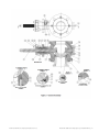
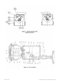
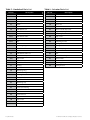
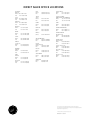
GE Oil & Gas
36005 Series V-Max*
Masoneilan* High Capacity Control Ball Valve
Instruction Manual
GE Data Classification : Public
b | GE Oil & Gas
© 2014 General Electric Company. All rights reserved.
THESE INSTRUCTIONS PROVIDE THE CUSTOMER/OPERATOR WITH IMPORTANT PROJECT-SPECIFIC REFERENCE INFORMATION
IN ADDITION TO THE CUSTOMER/OPERATOR’S NORMAL OPERATION AND MAINTENANCE PROCEDURES. SINCE OPERATION
AND MAINTENANCE PHILOSOPHIES VARY, GE (GENERAL ELECTRIC COMPANY AND ITS SUBSIDIARIES AND AFFILIATES) DOES
NOT ATTEMPT TO DICTATE SPECIFIC PROCEDURES, BUT TO PROVIDE BASIC LIMITATIONS AND REQUIREMENTS CREATED BY
THE TYPE OF EQUIPMENT PROVIDED.
THESE INSTRUCTIONS ASSUME THAT OPERATORS ALREADY HAVE A GENERAL UNDERSTANDING OF THE REQUIREMENTS
FOR SAFE OPERATION OF MECHANICAL AND ELECTRICAL EQUIPMENT IN POTENTIALLY HAZARDOUS ENVIRONMENTS.
THEREFORE, THESE INSTRUCTIONS SHOULD BE INTERPRETED AND APPLIED IN CONJUNCTION WITH THE SAFETY RULES
AND REGULATIONS APPLICABLE AT THE SITE AND THE PARTICULAR REQUIREMENTS FOR OPERATION OF OTHER EQUIPMENT
AT THE SITE.
THESE INSTRUCTIONS DO NOT PURPORT TO COVER ALL DETAILS OR VARIATIONS IN EQUIPMENT NOR TO PROVIDE FOR
EVERY POSSIBLE CONTINGENCY TO BE MET IN CONNECTION WITH INSTALLATION, OPERATION OR MAINTENANCE. SHOULD
FURTHER INFORMATION BE DESIRED OR SHOULD PARTICULAR PROBLEMS ARISE WHICH ARE NOT COVERED SUFFICIENTLY
FOR THE CUSTOMER/OPERATOR'S PURPOSES THE MATTER SHOULD BE REFERRED TO GE.
THE RIGHTS, OBLIGATIONS AND LIABILITIES OF GE AND THE CUSTOMER/OPERATOR ARE STRICTLY LIMITED TO THOSE
EXPRESSLY PROVIDED IN THE CONTRACT RELATING TO THE SUPPLY OF THE EQUIPMENT. NO ADDITIONAL REPRESENTATIONS
OR WARRANTIES BY GE REGARDING THE EQUIPMENT OR ITS USE ARE GIVEN OR IMPLIED BY THE ISSUE OF THESE
INSTRUCTIONS.
THESE INSTRUCTIONS CONTAIN PROPRIETARY INFORMATION OF GE, AND ARE FURNISHED TO THE CUSTOMER/OPERATOR
SOLELY TO ASSIST IN THE INSTALLATION, TESTING, OPERATION, AND/OR MAINTENANCE OF THE EQUIPMENT DESCRIBED.
THIS DOCUMENT SHALL NOT BE REPRODUCED IN WHOLE OR IN PART NOR SHALL ITS CONTENTS BE DISCLOSED TO ANY
THIRD PARTY WITHOUT THE WRITTEN APPROVAL OF GE.
© 2014 General Electric Company. All rights reserved.
Masoneilan 36005 Series High Capacity Control Ball Valves | c
Contents
Important : Safety Warning�������������������������������������������������������������������������������������������������������������������������������������������������������1
1.0 Introduction
Numbering System . . . . . . . . . . . . . . . . . . . . . . . . . . . . . . . . . . . . . . . . . . . . . . . . . . . . . . . . . . . . . . . . . . . . . . . . . . . . . . . . . . . . . . . . 2
2.0 Installation
2.1 General . . . . . . . . . . . . . . . . . . . . . . . . . . . . . . . . . . . . . . . . . . . . . . . . . . . . . . . . . . . . . . . . . . . . . . . . . . . . . . . . . . . . . . . . . . . . . . . . 4
2.2 Pipeline Mounting . . . . . . . . . . . . . . . . . . . . . . . . . . . . . . . . . . . . . . . . . . . . . . . . . . . . . . . . . . . . . . . . . . . . . . . . . . . . . . . . . . . . . . 4
2.3 Air Piping . . . . . . . . . . . . . . . . . . . . . . . . . . . . . . . . . . . . . . . . . . . . . . . . . . . . . . . . . . . . . . . . . . . . . . . . . . . . . . . . . . . . . . . . . . . . . . 4
2.4 Changing Actuator Position . . . . . . . . . . . . . . . . . . . . . . . . . . . . . . . . . . . . . . . . . . . . . . . . . . . . . . . . . . . . . . . . . . . . . . . . . . . . . 4
2.5 Changing valve ACTION . . . . . . . . . . . . . . . . . . . . . . . . . . . . . . . . . . . . . . . . . . . . . . . . . . . . . . . . . . . . . . . . . . . . . . . . . . . . . . . . 6
3.0 Maintenance
3.1 Bracket Subassembly . . . . . . . . . . . . . . . . . . . . . . . . . . . . . . . . . . . . . . . . . . . . . . . . . . . . . . . . . . . . . . . . . . . . . . . . . . . . . . . . . . . 8
3.3 Body Subassembly . . . . . . . . . . . . . . . . . . . . . . . . . . . . . . . . . . . . . . . . . . . . . . . . . . . . . . . . . . . . . . . . . . . . . . . . . . . . . . . . . . . . . 9
3.3.1 PackinG . . . . . . . . . . . . . . . . . . . . . . . . . . . . . . . . . . . . . . . . . . . . . . . . . . . . . . . . . . . . . . . . . . . . . . . . . . . . . . . . . . . . . . . . . . . . . 10
3.3.2 MN-7 Seal Ring . . . . . . . . . . . . . . . . . . . . . . . . . . . . . . . . . . . . . . . . . . . . . . . . . . . . . . . . . . . . . . . . . . . . . . . . . . . . . . . . . . . . . . 10
3.3.3 Standard Metal Seal Ring . . . . . . . . . . . . . . . . . . . . . . . . . . . . . . . . . . . . . . . . . . . . . . . . . . . . . . . . . . . . . . . . . . . . . . . . . . . . 10
3.3.4 Heavy Duty Metal Seal Ring . . . . . . . . . . . . . . . . . . . . . . . . . . . . . . . . . . . . . . . . . . . . . . . . . . . . . . . . . . . . . . . . . . . . . . . . . . 11
3.3.5 Ball Plug . . . . . . . . . . . . . . . . . . . . . . . . . . . . . . . . . . . . . . . . . . . . . . . . . . . . . . . . . . . . . . . . . . . . . . . . . . . . . . . . . . . . . . . . . . . . 11
3.4 Actuator Subassembly . . . . . . . . . . . . . . . . . . . . . . . . . . . . . . . . . . . . . . . . . . . . . . . . . . . . . . . . . . . . . . . . . . . . . . . . . . . . . . . .12
3.5 Handwheel Subassembly . . . . . . . . . . . . . . . . . . . . . . . . . . . . . . . . . . . . . . . . . . . . . . . . . . . . . . . . . . . . . . . . . . . . . . . . . . . . . . 14
3.6 Diaphragm Replacement . . . . . . . . . . . . . . . . . . . . . . . . . . . . . . . . . . . . . . . . . . . . . . . . . . . . . . . . . . . . . . . . . . . . . . . . . . . . . .15
Figure 1 — Numbering System and Standard
Mounting Positions . . . . . . . . . . . . . . . . . . . . . . . . . . . . . . . . . . . . . . . . . . . . . . . . . . . . . . . . . . . . . . . . . . . . . . . . . . . . . 2
Figure 2 — General Assembly . . . . . . . . . . . . . . . . . . . . . . . . . . . . . . . . . . . . . . . . . . . . . . . . . . . . . . . . . . . . . . . . . . . . . . . . . . . . . . 17
Figure 3 — Actuator Sizes B & C Bracket & Linkage . . . . . . . . . . . . . . . . . . . . . . . . . . . . . . . . . . . . . . . . . . . . . . . . . . . . . . . . . 18
Figure 4 — Handwheel Assembly, Actuator Sizes B & C . . . . . . . . . . . . . . . . . . . . . . . . . . . . . . . . . . . . . . . . . . . . . . . . . . . . . 18
Figure 5 — Handwheel Detail, Actuator Sizes B & C . . . . . . . . . . . . . . . . . . . . . . . . . . . . . . . . . . . . . . . . . . . . . . . . . . . . . . . . . 18
Figure 6 — Handwheel Bracket Detail, Sizes B & C . . . . . . . . . . . . . . . . . . . . . . . . . . . . . . . . . . . . . . . . . . . . . . . . . . . . . . . . . . 18
Figure 7 — Handwheel Lever Detail, Sizes B & C . . . . . . . . . . . . . . . . . . . . . . . . . . . . . . . . . . . . . . . . . . . . . . . . . . . . . . . . . . . . 18
Figure 8 — Handwheel Clevis Detail, Sizes B & C . . . . . . . . . . . . . . . . . . . . . . . . . . . . . . . . . . . . . . . . . . . . . . . . . . . . . . . . . . . . 18
Figure 9 — AcTuator General Assembly, Sizes B & C . . . . . . . . . . . . . . . . . . . . . . . . . . . . . . . . . . . . . . . . . . . . . . . . . . . . . . . . . 19
Figure 10 — Lever Position Air to Open, Sizes B & C . . . . . . . . . . . . . . . . . . . . . . . . . . . . . . . . . . . . . . . . . . . . . . . . . . . . . . . . . 19
Figure 11 — Lever Position Air to Close, Sizes B & C . . . . . . . . . . . . . . . . . . . . . . . . . . . . . . . . . . . . . . . . . . . . . . . . . . . . . . . . . 19
Figure 12 — Position Indicator Detail, Sizes B & C . . . . . . . . . . . . . . . . . . . . . . . . . . . . . . . . . . . . . . . . . . . . . . . . . . . . . . . . . . . 20
Figure 13 — Size AC Actuator Assembly . . . . . . . . . . . . . . . . . . . . . . . . . . . . . . . . . . . . . . . . . . . . . . . . . . . . . . . . . . . . . . . . . . . . 20
Figure 14 — Size AC Actuator Bottom View . . . . . . . . . . . . . . . . . . . . . . . . . . . . . . . . . . . . . . . . . . . . . . . . . . . . . . . . . . . . . . . . . 21
Figure 15 — Size AC Actuator Linkage Detail . . . . . . . . . . . . . . . . . . . . . . . . . . . . . . . . . . . . . . . . . . . . . . . . . . . . . . . . . . . . . . . 21
Figure 16 — Size AC Handwheel Detail . . . . . . . . . . . . . . . . . . . . . . . . . . . . . . . . . . . . . . . . . . . . . . . . . . . . . . . . . . . . . . . . . . . . . 22
Figure 17 — insulation Detail . . . . . . . . . . . . . . . . . . . . . . . . . . . . . . . . . . . . . . . . . . . . . . . . . . . . . . . . . . . . . . . . . . . . . . . . . . . . . . 22
Table 1 — Body Parts List . . . . . . . . . . . . . . . . . . . . . . . . . . . . . . . . . . . . . . . . . . . . . . . . . . . . . . . . . . . . . . . . . . . . . . . . . . . . . . . . . . 23
Table 2 — Bracket and Linkage Parts List . . . . . . . . . . . . . . . . . . . . . . . . . . . . . . . . . . . . . . . . . . . . . . . . . . . . . . . . . . . . . . . . . . 23
Table 3 — Handwheel Parts List . . . . . . . . . . . . . . . . . . . . . . . . . . . . . . . . . . . . . . . . . . . . . . . . . . . . . . . . . . . . . . . . . . . . . . . . . . . 24
Table 4 — Actuator Parts List . . . . . . . . . . . . . . . . . . . . . . . . . . . . . . . . . . . . . . . . . . . . . . . . . . . . . . . . . . . . . . . . . . . . . . . . . . . . . . 24
Table 5 — Line Bolting . . . . . . . . . . . . . . . . . . . . . . . . . . . . . . . . . . . . . . . . . . . . . . . . . . . . . . . . . . . . . . . . . . . . . . . . . . . . . . . . . . . . . 25
d | GE Oil & Gas
© 2014 General Electric Company. All rights reserved.
WARNING
Safety Information
CAUTION
Important - Please Read Before Installation
Masoneilan 36005 Series instructions contain DANGER,
WARNING, and CAUTION labels, where necessary, to alert
you to safety related or other important information. Read the
instructions carefully before installing and maintaining your
control valve. DANGER and WARNING hazards are related to
personal injury. CAUTION hazards involve equipment or property
damage. Operation of damaged equipment can, under certain
operational conditions, result in degraded process system
performance that can lead to injury or death. Total compliance
with all DANGER, WARNING, and CAUTION notices is required
for safe operation.
CAUTION
WARNING
This is the safety alert symbol. It alerts you to potential
personal injury hazards. Obey all safety messages that
follow this symbol to avoid possible injury or death.
WARNING
DANGER
CAUTION
Indicates a potentially hazardous situation which, if not avoided,
could result in death or serious injury.
CAUTION
WARNING
Indicates a potentially hazardous situation which, if not avoided,
could result in serious injury.
CAUTION
WARNING
CAUTION
CAUTION
Indicates a potentially hazardous situation which, if not avoided,
could result in minor or moderate injury.
About this Manual
• The information in this manual is subject to change without
prior notice.
• The information contained in this manual, in whole or part,
shall not be transcribed or copied without GE’s written
permission.
• Please report any errors or questions about the information in
this manual to your local supplier.
• These instructions are written specifically for the 36005 Series
control valves, and do not apply for other valves outside of
this product line.
Warranty
Items sold by General Electric are warranted to be free from
defects in materials and workmanship for a period of one
year from the date of shipment provided said items are used
according to GE recommended usages. GE reserves the right
to discontinue manufacture of any product or change product
materials, design or specifications without notice.
This instruction manual applies to the Masoneilan 36005 Series
control valves.
The Control Valve MUST BE:
• Installed, put into service and maintained by qualified
and competent professionals who have undergone
suitable training.
• Under certain operating conditions, the use of damaged
equipment could cause a degradation of the performance
of the system which may lead to personal injury or death.
• Changes to specifications, structure, and components used
may not lead to the revision of this manual unless such
changes affect the function and performance of the product.
• All surrounding pipe lines must be thoroughly flushed to
ensure all entrained debris has been removed from the
system.
CAUTION
CAUTION
When used without the safety alert symbol indicates a
potentially hazardous situation which, if not avoided, could
result in property damage.
CAUTION
DANGER
Note: Indicates important facts and conditions.
DANGER
DANGER
DANGER
© 2014 General Electric Company. All rights reserved.
Masoneilan 36005 Series High Capacity Control Ball Valves | 1
1.0 Introduction
The following instructions are designed to assist
maintenance personnel in performing most of the
maintenance required on the 36005 V-Max* valve and if
followed carefully will reduce maintenance time.
GE Masoneilan has highly skilled Service Engineers
available for start-up, maintenance and repair of our
valves and component parts. In addition, regularly
scheduled training programs are conducted to train
customer service and instrumentation personnel in
the operation, maintenance and application of our
control valves and instruments. Arrangements for these
services can be made through your GE Masoneilan
Representative or District Office. When performing
maintenance use only Masoneilan replacement parts.
Parts are obtainable through your local GE Masoneilan
Representative or District Office. When ordering parts
always include MODEL and SERIAL NUMBER of the unit
being repaired.
Numbering System
1st
2nd
Actuator Type
33 Spring Diaphragm. Air to
extend action only.
2 | GE Oil & Gas
1st
3
Body Series
36
2nd
6
3rd
4th
Actuator Mounting
(See guide on page 4)
0 Undefined
1 Valve closes on stem
extension (Air to Close,
Fail Open)
2 Valve opens on stem
extension (Air to Open,
Fail Closed
3 Valve closes on stem
extension (Air-to-Close,
Fail Open)
4 Valve opens on stem
extension (Air-to-Open,
Fail Closed)
7 Valve closes on stem
extension (Air-to-Close,
Fail Open)
8 Valve opens on stem
extension (Air-to-Open,
Fail Closed)
5th
5
Seal Type
Design Series
1 MN-7 Seal Ring
2 316 SS Seal
Ring
3 Heavy Duty
Metal Seal Ring
5
© 2014 General Electric Company. All rights reserved.
V-Max Valves
Actuator Model 33, Size AC
3
X
3
6
X
0
5
Actuator Position in Relation to Valve Body
Numbering System: 1 to 8
Actuator Model 33, Sizes B and C
© 2014 General Electric Company. All rights reserved.
Masoneilan 36005 Series High Capacity Control Ball Valves | 3
CAUTION
2.0 Installation
WARNING
2.1 General
2.1.1 Unpack valve carefully to avoid damage to valve,
accessories, or tubing.
2.1.2 Record all valve and accessory serial plate data
for future reference. Always provide serial and model
numbers when ordering spare parts.
CAUTION
2.2 Pipeline Mounting
CAUTION
Do not remove button head screw (9) and
washer (10) during installation. The function
of these parts is to hold the retainer (3) and
seal ring (8) in place and should be removed
only when the valve is to be disassembled for
maintenance (Figure 2).
A. B
efore installing the valve in the line, clean pipe and
valve of all foreign materials such as welding chips,
scale, oil, grease or dirt. Gasket surfaces must be
thoroughly cleaned to ensure leak free joints.
DANGER
B. Install valve in a horizontal or vertical line with the flow
tending to push the seal ring (8) against the ball (2) as
indicated by the flow arrow cast into the body. It is
recommended that if adjacent walls and piping permit,
the valve be oriented such that the ball opens upward.
This is especially important when handling slurries. See
Figure 1 for actuator mounting positions and for flow
direction and Table 5 for line flange bolting lengths.
Note: Flange bolt lengths are non-standard on inlet and
standard on outlet side.
C. T ighten bolting evenly and in crisscross fashion so that
the retainer (3) held in place by the line flange will bear
evenly against the seal ring (8).
D. The linkage of the 36005 V-Max valve has been
properly adjusted at the factory and requires no further
adjustment.
E. Where insulation of the valve body is required, do not
insulate the valve bonnet. See Figure 17.
2.3 Air Piping
2.3.1 Air piping must be adequately sized to provide the
regulated supply pressure specified on the nameplate. As
a general guideline, use 1/4" O.D. tubing or equivalent for
all air lines. If supply air line exceeds 25 feet in length, use
3/8" O.D. tubing.
2.3.2 The actuator is furnished with a 1/4" NPT instrument
air port on the upper case.
4 | GE Oil & Gas
CAUTION
Before proceeding with changing actuator
position, air action or valve maintenance,
isolate valve, vent process pressure and shut
off air supply and signal air lines or electrical
lines to unit. It is recommended that the
valve be removed from the pipeline prior to
maintenance work. Keep hands and tools away
from the segmental ball, particularly when
disconnecting the actuator stem from shaft
arm as ball may rotate freely to its lowest
position
DANGER
For each valve action (air to open/air to close) the
actuator may be positioned to either side of the pipe.
Actuator position is usually determined by adjacent
piping, obstacles of various types or air piping
arrangements. To reposition the actuator and/or bracket
follow the disassembly and reassembly instructions
below.
Note: Actuator positioning should be performed
prior to installing the valve in the pipeline. To change
actuator position and/or valve action refer to Figure 1
for desired position.
A. Remove valve from process line after closing isolating
valves and disconnecting all pneumatic tubing and
electrical wiring.
B. If valve is equipped with a handwheel (Figure 4)
disengage handwheel and remove retaining clips (63),
clevis pin (66) and pivot pins (72); remove entire handwheel assembly from bracket (62).
C. Remove pivot pin retaining clips (40), pivot pin (39) and
spacer rings (69). Remove actuator hex nuts (75) and
washers (76). Remove actuator.
Note: Spacer rings apply only on handwheel option.
D. Remove shaft cover (42) and screw (43). Loosen lever
cap screw (33). Remove packing flange stud nuts (24),
bracket mounting stud nuts (24) and washers (18).
Loosen ball plug indicator arm (35).
E. If necessary, scribe a witness line on the lever (32)
in relation to the slot on the end of the shaft (5).
Note: Standard lever has arrows stamped into it for
alignment. For handwheel lever use slot for alignment.
F. Slide bracket (31) away from body until it clears bracket
and packing flange studs (26 and 25), allowing lever
(32) lever arm (64) and indicator arm (35) to be removed
from shaft. Total removal of the bracket is not required.
© 2014 General Electric Company. All rights reserved.
CAUTION
CAUTION
Before proceeding determine valve action (air
to open/air to close), refer to the appropriate
figure (Figure 10 to open, Figure 11 to close).
To obtain proper alignment, the lever must be
oriented on the shaft so that the slot in the end
of the shaft and arrows or indicator lines are
aligned as shown; with the ball in the closed
position, the distance between the top of the
bracket and the top of the pivot pin must be as
shown.
DANGER
G. Slide lever (32) and lever arm (64) back onto shaft in
desired position. Slide indicator arm (35) back onto
shaft. Align bracket and slide back onto bracket
mounting studs (26) and packing flange studs (25).
Replace bracket mounting stud nuts (24) and washers
(18). Slide packing flange (23) back onto packing flange
studs (25) and replace packing flange stud nuts (24).
WARNING
H. Remount actuator onto bracket and replace actuator
mounting hex nuts (75) and washers (76). Position lever
(32) and lever arm (64) so that rod end bearing (94) lines
up in lever (32). Tighten lever cap screws (34).
I. R
otate ball plug (2) to closed position. If actuator action
is air to open loosen rod end bearing locknut (93) and
adjust position of rod end bearing (94) so that holes in
lever (32) and rod end bearing (94) line up. Insert pivot
pin (39) and replace spacer rings (69) and retaining rings
(40).
CAUTION
WARNING
CAUTION
When stroking valve keep hands and
equipment clear of ball plug and seal ring
to avoid injury or damage to personnel and
equipment.
CAUTION
J. If action is air to close place ball plug (2) in closed
position and pneumatically stroke actuator fully.
CAUTION
Do not exceed maximum air supply pressure.
Keep hands clear of actuator stem and linkage.
DANGER
Loosen rod end bearing locknut (93) and adjust rod end
bearing (94) so that holes in lever (32) and rod end bearing
(94) line up. Insert pivot pin (39) and spacers (69) and
replace retaining rings (40).
K. For both air to open and air to close action, stroke valve
fully to ensure proper closure of ball plug and operation
of valve. It may be necessary to readjust rod end
DANGER
© 2014 General Electric Company. All rights reserved.
WARNING
bearing slightly by loosening locknut and rotating stem.
L. Replace handwheel assembly in bracket (62), pivot pins
(72) and retaining clips (63).
CAUTION
M. Replace shaft cover (42) and screw (43).
N. S
et and lock indicator arm (35) to indicate plug position.
2.4.2 Changing Actuator Position Model 33, size AC only.
CAUTION
Before proceeding with changing actuator
position, air action or valve maintenance,
isolate valve, vent process pressure and shut
off air supply and signal air lines or electrical
lines to unit. It is recommended that the
valve be removed from the pipeline prior to
maintenance work. Keep hands and tools away
from the segmental ball, particularly when
disconnecting the actuator stem from shaft
arm as ball may rotate freely to its lowest
position.
DANGER
For each valve action (air to open/air to close) the
actuator may be positioned to either side of the pipe.
Actuator position is usually determined by adjacent
piping, obstacles of various types or air piping
arrangements. To reposition the actuator and/or bracket
follow the disassembly and reassembly instructions
below.
Note: Actuator positioning should be performed
prior to installing the valve in the pipeline. To change
actuator position and/or valve action refer to Figure 1
for desired position.
A. Remove valve from process line after closing isolating
valves and disconnecting all pneumatic tubing and
electrical wiring.
B. If valve is equipped with a handwheel (Figures 13 & 16)
disengage handwheel and remove retaining clip (54-7)
and washer (54-4). Remove entire handwheel assembly
from actuator housing (31).
C. Remove pivot pin retaining clips (40), pivot pin (39).
Remove actuator hex nuts (75) and washers (76).
Remove actuator.
D. Remove shaft cover (42) and screw (43). Loosen lever
cap screw (33). Remove packing flange stud nuts (24),
bracket mounting stud nuts (24) and washers (18).
Loosen ball plug indicator arm (35).
E. If necessary, scribe a witness line on the lever (32) in
relation to the slot on the end of the shaft (5).
F. Slide housing (31) away from body until it clears bracket
and packing flange studs (26 and 25), allowing lever (32)
and indicator arm (35) to be removed from shaft. Total
Masoneilan 36005 Series High Capacity Control Ball Valves | 5
CAUTION
removal of the bracket is not required.
CAUTION
Before proceeding determine valve action (air
to open/air to close).
G. Slide lever (32) back onto shaft in desired position.
Slide indicator arm (35) back onto shaft. Align bracket
and slide back onto mounting studs (26) and packing
flange studs (25). Replace mounting stud nuts (24)
and washers (18). Slide packing flange (23) back onto
packing flange studs (25) and replace packing flange
stud nuts (24).
H. R
emount actuator onto housing and replace actuator
mounting hex nuts (75) and washers (76). Position lever
(32) so that rod end bearing (94) lines up in lever (32)
and that the pads on the lever will contact the stop
bolts (102). Tighten lever cap screw (33).
DANGER
WARNING
I. R
otate ball plug (2) to closed position. Adjust closed
position travel stop (102) until it contacts the pad on
lever (32). Tighten locknut (101).
CAUTION
J. R
otate ball plug (2) to open position. Adjust open
position travel stop until it contacts pad on lever (32).
Tighten locknut (101).
CAUTION
EnsureWARNING
rotation of AC actuator does not
exceed 90deg. Damage to actuator rod may
result.
K. If actuator action is air to open, rotate ball plug (2) to
open position. Pneumatically stroke actuator to open
position. Loosen rod end bearing locknut (93) and
adjust position of rod end bearing (94) so that holes in
lever (32) and rod end bearing (94) line up. Insert pivot
pin (39) and retaining rings (40).
CAUTION
CAUTION
DANGER
When stroking valve keep hands and
equipment clear of ball plug and seal ring
to avoid injury or damage to personnel and
equipment.
L. If action is air to close place ball plug (2) in closed
position. The pad on lever should contact the closed
position travel stop (102). If it does not, repeat
adjustment as noted in step I above. Return ball plug (2)
to open position. Pneumatically stroke actuator to open
position.
DANGER
6 | GE Oil & Gas
CAUTION
CAUTION
Do not exceed maximum air supply pressure.
Keep hands clear of actuator stem and linkage.
Loosen rod end bearing locknut (93) and adjust rod end
bearing (94) so that holes in lever (32) and rod end bearing
(94) line up. Insert pivot pin (39) and replace retaining rings
(40).
M. For both air to open and air to close action, stroke
valve fully to ensure proper closure of ball plug and
operation of valve. It may be necessary to readjust rod
end bearing slightly by loosening locknut and rotating
stem.
DANGER
N. R
eplace handwheel assembly in housing (31), washer
(54-7) and retaining clip (54-4).
O. Replace shaft cover (42) and screw (43).
P. Set and lock indicator arm (35) to indicate plug position.
2.5 Changing Valve Action
Note: If the valve action is to be changed it should be
done before the valve is installed in the line. This allows
a positive visual check to ensure that the ball plug is
fully closed when the actuator is in the proper position.
2.5.1 Model 33, sizes B & C only. For size AC refer
to section 2.5.2
A. If the valve is equipped with a handwheel disengage
the handwheel and remove retaining clips (63), clevis
pin (66), and pivot pins (39). Remove cap screws (70),
washers (71) and handwheel bracket (62).
B. If necessary, scribe a witness mark on the lever
(32) in relation to the slot on the end of the shaft (5).
Note: Standard lever has arrows stamped into it for
alignment. For handwheel lever use slot for alignment.
C. Remove pivot pin retaining clips (40), pivot pin (39) and
spacer rings (69). Remove shaft cover (42) and screw
(43). Remove actuator hex nuts (75) and washers (76).
Remove actuator.
WARNING
Note: Spacer rings apply only on handwheel option.
D. Loosen lever cap screw (33). Remove packing flange
stud nuts (24), bracket mounting stud nuts (24) and
washers (18). Loosen ball plug indicator arm (35).
CAUTION
E. Slide bracket (31) away from body until it clears bracket
and packing flange mounting studs. Remove lever (32),
lever arm (64) and indicator arm (35) from shaft.
CAUTION
Before proceeding determine valve action (air
to open/air to close), refer to the appropriate
© 2014 General Electric Company. All rights reserved.
figure (Figure 10 to open, Figure 11 to close).
To obtain proper alignment, the lever must be
oriented on the shaft so that the slot in the end
of the shaft and arrows or indicator lines are
aligned as shown; with the ball in the closed
position, the distance between the top of the
bracket and the top of the pivot pin must be as
shown.
F. Flip lever (32) and lever arm (64) and replace on shaft
90 away from original position. Replace indicator arm
(35). Slide bracket back onto bracket mounting studs
(26), replace washers (18) and nuts (24) and tighten. Slide
packing flange (23) back over packing flange studs (25)
and replace packing flange stud nuts (24) and tighten.
G. Replace actuator on bracket in correct mounting
position for air action. Replace actuator stud nuts (75)
and washers (76). Position lever (32) and lever arm
(64) so that rod end bearing (94) lines up in lever (32).
Tighten lever cap screw (33).
WARNING
H. Place ball plug (2) in closed position. If actuator action
is air to open, loosen rod end bearing nut (93) and
adjust position of rod end bearing (94) so that holes in
lever (32) and rod end bearing (94) line up. Insert pivot
pin (39) and replace retaining rings (40).
CAUTION
WARNING
I. If action is air to close, place ball plug (2) in closed
position and pneumatically stroke actuator fully.
CAUTION
Do not exceed maximum air supply pressure.
CAUTION
J. F or both air to open and air to close action, stroke valve
fully to ensure proper closure of ball plug and operation
of valve. Tighten rod end bearing locknut (93).
CAUTION
When stroking valve keep hands and
equipment clear of ball plug and seal ring
to avoid injury or damage to personnel or
equipment.
DANGER
K. R
eplace handwheel bracket (62), cap screws (70)
and lockwashers (71) on opposite side of actuator
bracket from where originally found. Insert handwheel
assembly in bracket and replace clevis pin (66),
retaining rings (63), lever arm bearing (65) and pivot
pins (72). Replace shaft cover (42) and screw (43).
DANGER
L. Set and lock indicator (35) to indicate plug position.
2.5.2 Model 33, size AC only. For sizes B & C refer
to section 2.5.1 above.
A. If the valve is equipped with a handwheel disengage
© 2014 General Electric Company. All rights reserved.
the handwheel and remove retaining clip (54-7) and
washer (54-4). Remove handwheel assembly (54) from
housing (31) by rotating counter-clockwise.
B. Remove pivot pin retaining clips (40), pivot pin (39).
Remove actuator hex nuts (75) and washers (76).
Remove actuator.
C. R
emove cover (48) from opposite side of bracket (31)
and install on side actuator was just removed from.
WARNING
Note: Cover (48) is attached to yoke with contact
adhesive that is pre-applied. If a new cover is not
available, it can be re-installed by applying contact
adhesive to the cover and bracket following the
instructions for the specific adhesive used.
CAUTION
D. Install actuator on opposite side of yoke than it was
removed from. Attach using washers (76) and hex nuts
(75).
WARNING
CAUTION
Before proceeding determine valve action (air
to open/air to close).
CAUTION
E. Rotate ball plug (2) to closed position. Verify closed
position travel stop (102) contacts the pad on lever (32).
Adjust as necessary. Tighten locknut (101).
CAUTION
Ensure rotation of AC actuator does not
exceed 90deg. Damage to actuator rod may
result.
DANGER
WARNING
F. Rotate ball plug (2) to open position. Verify open
position travel stop contacts pad on lever (32). Adjust as
necessary. Tighten locknut (101).
G. If actuator action is air to open, rotate ball plug (2) to
open position. Pneumatically stroke actuator to open
position. Loosen rod end bearing locknut (93) and
adjust position of rod end bearing (94) so that holes in
lever (32) and rod end bearing (94) line up. Insert pivot
pin (39) and retaining rings (40).
CAUTION
DANGER
CAUTION
When stroking valve keep hands and
equipment clear of ball plug and seal ring
to avoid injury or damage to personnel and
equipment.
H. If action is air to close place ball plug (2) in closed
position. The pad on lever should contact the closed
position travel stop (102). If it does not, repeat
Masoneilan 36005 Series High Capacity Control Ball Valves | 7
CAUTION
adjustment as noted in step I above. Return ball plug (2)
to open position.
CAUTION
Do not exceed maximum air supply pressure.
Keep hands clear of actuator stem and linkage.
Loosen rod end bearing locknut (93) and adjust rod end
bearing (94) so that holes in lever (32) and rod end bearing
(94) line up. Insert pivot pin (39) and replace retaining rings
(40).
I. F or both air to open and air to close action, stroke valve
fully to ensure proper closure of ball plug and operation
of valve. It may be necessary to readjust rod end
bearing slightly by loosening locknut and rotating stem.
DANGER
WARNING
J. R
eplace handwheel assembly (54) in bracket (31),
washer (54-7) and retaining clip (54-4).
K. Set and lock indicator arm (35) to indicate plug position.
3.0 Maintenance
CAUTION
3.1 Bracket Subassembly – Model 33, sizes B &
C only. Refer to section 3.2 for size AC
3.1.1 Disassembly
CAUTION
When disconnecting actuator rod end bearing
from shaft arm, the ball is likely to rotate
toward the bottom of the valve body. Keep
hands and tools away from the ball.
A. R
emove screw (43) and shaft cover (42) or positioner if
so equipped.
B. Remove retaining clips (40), pivot pin (39) and spacer
rings (69).
Note: Spacer rings apply only on handwheel option.
DANGER
C. R
emove actuator mounting nuts (75) and washers (76)
and remove actuator from bracket (31).
D. If valve has handwheel, remove retainer clips (63), clevis
pin (66), pivot pins (72). Remove handwheel assembly
from bracket.
E. Loosen cap screw (33) and indicator arm (35). Remove
packing flange stud nuts (24) and bracket mounting
stud nuts (26) and washers (18).
F. Scribe a witness mark on the lever (32) indicating
relative position to the slot in the end of the shaft (5).
G. Slide bracket (31) off studs and shaft, removing
indicator arm (35), lever (32), lever arm (64) and packing
flange (23).
8 | GE Oil & Gas
emove bearing (47) from bracket. Examine all parts for
H. R
wear and/or damage. Replace if necessary.
3.1.2 Reassembly
Note: If the valve is equipped with a handwheel the
lever consists of two separate arms which are a
MATCHED PAIR and are not interchangeable with any
other pair. The sequence of assembly is to place one
lever over the shaft then the lever arm (64) insert pin
(68), and then the second lever arm onto the shaft then
slide the shaft into the bracket and bearing.
A. Replace ball bearing (47) in the bracket (31).
B. Place ball plug (2) in closed position. Slide bracket (31)
partially over shaft. Ensure all packing box parts are
in place and then slide packing flange (23) onto shaft.
Slide lever (32) onto shaft on its former position. Slide
handwheel lever arm (64) and second lever (32) onto
shaft if valve has handwheel. Replace indicator arm
(35). Slide bracket fully onto mounting studs (26); ensure
shaft (5) is properly located in bearing (47). Replace lockwasher (18) and bracket mounting stud nuts (24) and
tighten. Replace packing flange stud nuts (24).
C. Pull shaft out to bottom against bearing. Replace
actuator and install washers (76) and nuts (75). Slide
lever (32) on shaft so that it is lined up with rod end
bearing (94). Tighten lever locking screw (33).
WARNING
D. If valve action is air to open place ball plug (2) in
closed position. Loosen rod end bearing locknut (93)
and adjust rod end bearing until holes in lever (32)
and rod end bearing (94) line up. Install pivot pin (39),
spacers (69) (handwheel only) and retainer rings (40). If
valve action is air to close, place ball plug (2) in closed
position and pneumatically stroke actuator fully.
CAUTION
WARNING
CAUTION
Do not exceed maximum air supply pressure
specified on the valve nameplate.
CAUTION
E. For both air to open and air to close action, stroke valve
fully to ensure proper closure of ball plug and operation
of valve. Tighten rod end bearing locknut (93).
CAUTION
When stroking valve keep hands and
equipment clear of ball plug and seal ring
to avoid injury or damage to personnel or
equipment. Do not exceed pressure specified
on the valve nameplate.
DANGER
F. Replace shaft cover (42) and screw (43) (or positioner if
so equipped).
G. Replace handwheel assembly in bracket (62) and
© 2014 General Electric Company. All rights reserved.
replace clevis pin (66), retaining clips (63), and pivot pins
(72).
H. Set and lock indicator arm (35) to indicate plug position.
WARNING
I. Check that handwheel operates valve through full range
of travel. There is a 1/2" adjustment available at the end
of the handwheel extension. Retract handwheel, remove
end cap (51) and cap screw (55B). Rearrange stop (55A)
and/or spacer (55C) to obtain desired extension.
CAUTION
3.2 Bracket Subassembly – Model 33, size AC
only. Refer to section 3.1 for sizes B & C
3.2.1 Disassembly
CAUTION
When disconnecting actuator rod end bearing
from shaft arm, the ball is likely to rotate
toward the bottom of the valve body. Keep
hands and tools away from the ball.
A. R
emove screw (43) and shaft cover (42) or positioner if
so equipped.
B. Remove retaining clips (40), pivot pin (39).
C. Remove actuator mounting nuts (75) and washers (76)
and remove actuator from bracket (31).
DANGER
D. If valve has handwheel, remove retainer clip (54-7) and
washer (54-4). Remove handwheel assembly (54) from
bracket.
E. Loosen cap screw (36) and indicator arm (35). Remove
packing flange stud nuts (24) and bracket mounting
stud nuts (26) and washers (18).
F. Scribe a witness mark on the lever (32) indicating
relative position to the slot in the end of the shaft (5).
Loosen cap screw (11).
G. Slide bracket (31) off studs and shaft, removing
indicator arm (35), lever (32) and packing flange (23).
H. Remove bearing (47) and grommet (106) from bracket.
Examine all parts for wear and/or damage. Replace if
necessary.
3.2.2 Reassembly
A. Replace ball bearing (47) and grommet (106) in the
housing (31). Note, the grommet has a recessed area on
one side. It should be installed with that side should be
toward the inside of the bracket.
B. Place ball plug (2) in closed position. Slide bracket (31)
partially over shaft. Ensure all packing box parts are
in place and then slide packing flange (23) onto shaft.
Slide lever (32) onto shaft on its former position. Replace
indicator arm (35). Slide bracket fully onto mounting
© 2014 General Electric Company. All rights reserved.
studs (26); ensure shaft (5) is properly located in bearing
(47). Replace lockwasher (18) and bracket mounting
stud nuts (24) and tighten. Replace packing flange stud
nuts (24).
WARNING
C. Pull shaft out to bottom against bearing. Replace
actuator and install washers (76) and nuts (75). Slide
lever (32) on shaft so that it is lined up with rod end
bearing (94). Tighten lever locking screw (33).
D. Place ball plug (2) in closed position. If valve action is
air to close, pneumatically stroke actuator fully. Loosen
rod end bearing locknut (93) and adjust rod end bearing
until holes in lever (32) and rod end bearing (94) line up.
Install pivot pin (39) and clips (40).
CAUTION
WARNING
CAUTION
Do not exceed maximum air supply pressure
specified on the valve nameplate.
CAUTION
E. For both air to open and air to close action, stroke valve
fully to ensure proper closure of ball plug and operation
of valve. Tighten rod end bearing locknut (93).
CAUTION
When stroking valve keep hands and
equipment clear of ball plug and seal ring
to avoid injury or damage to personnel or
equipment. Do not exceed pressure specified
on the valve nameplate.
DANGER
F. Replace shaft cover (42) and screw (43) (or positioner if
so equipped).
G. Replace handwheel assembly (54) in housing (31) and
replace washer (54-4) and retaining clip (54-7).
DANGER
H. S
et and lock indicator arm (35) to indicate plug position.
I. Check that handwheel operates valve through full range
of travel.
3.3 Body Subassembly
3.3.1 Packing
Note: The packing follower should be held firmly, but
not too tightly against the packing.
Overtightening of the packing causes excessive friction
and may affect valve operation. The packing in a new
V-Max valve has not been tightened prior to shipment. It
is recommended that further adjustments be made when
the valve is put into service. If necessary to add packing,
proceed as follows:
Masoneilan 36005 Series High Capacity Control Ball Valves | 9
CAUTION
CAUTION
CAUTION
CAUTION
When stroking valve keep hands and
equipment clear of ball plug and seal ring
to avoid injury or damage to personnel or
equipment. Do not exceed pressure specified
on the valve nameplate.
DO NOT overtighten packing nuts.
F. Replace shaft cover (42) and screw (43) (or positioner if
so equipped).
3.3.2.1 Disassembly
Note: Seal ring removal, inspection and reinstallation
must be done with the valve removed from the
pipeline.
G. Replace handwheel assembly (54) in housing (31) and
replace washer (54-4) and retaining clip (54-7).
DANGER
H. S
et and lock indicator arm (35) to indicate plug position.
I. C
heck that handwheel operates valve through full range
of travel.
D. P
lace valve into service and tighten packing nuts (24)
only as much as necessary to stop any leakage.
3.3.2 Seal Ring – MN-7 Seal
DANGER
A. Remove screws (9) and washers (10), retainer (3), MN-7
seal ring (8) and downstream back-up ring (32).
B. Remove gasket (4) residue from body and retainer
taking care not to damage seal surfaces.
3.3 Body Subassembly
3.3.2.2 Reassembly
3.3.1 Packing
Note: The packing follower should be held firmly, but
not too tightly against the packing.
A. Move ball to the closed position.
Overtightening of the packing causes excessive friction
and may affect valve operation. The packing in a new
V-Max valve has not been tightened prior to shipment. It
is recommended that further adjustments be made when
the valve is put into service. If necessary to add packing,
proceed as follows:
B. Replace backup ring (32), seal assembly, gasket (4) and
retainer (3). Take care that beveled edges of seal (8) and
backup ring (32) are facing the ball.
WARNING
CAUTION
CAUTION
Valve must be isolated and process pressure
vented before performing packing box
maintenance.
3.3.1.1 Disassembly
A. Loosen and remove packing flange nuts (24) and
slide packing flange (23) and packing follower (20)
toward shaft lever (32). Note: The lever (32) may be
disconnected from the actuator stem and pushed up
against the shaft bearing (47) (refer to section 3.1), if
necessary for clearance.
DANGER
B. Using a packing hook, remove the top pieces of packing
rings.
3.3.1.2 Reassembly
A. Install new packing ring(s), making sure the skive cut in
adjacent packing rings is offset 120° apart.
B. Replace packing follower (20) packing box flange (23)
and packing nuts (24).
C. Evenly tighten packing nuts (24).
10 | GE Oil & Gas
Note: Use a light coating of Dow-Corning 111® or
equal on the ball plug to break in seat.
C. Replace set screws (9) and washers (10) and tighten.
3.3.3 Seal Ring – Standard Metal Seal
3.3.3.1 Disassembly
Note: Seal ring removal, inspection and reinstallation
must be done with the valve removed from the
pipeline.
A. Remove screws (9) and washers (10).
Note: The flexible metal seal assembly consists of a
seal ring (8), gasket (7), and backup ring (6).
B. Mark flexible metal seal ring (8) so that, if reinstalled,
the same side will be in contact with the ball. Remove
retainer, seal assembly and downstream back-up
ring (32). If difficulty is encountered in removing seal
assembly, rotate the ball to open position and pull out
the seal ring.
C. Remove gasket (4) residue from body and retainer
taking care not to damage seal surfaces.
D. If replacing MN-7 or flat metal seal with HD metal
version, upper and lower guide bushings (16, 17) should
be replaced with satellite material.
3.3.3.2 Reassembly
Note: If retrofitting a valve originally equipped with an
MN-7 seal ring follow steps A through D. If valve was
originally supplied with a metal seal, please proceed to
step C.
© 2014 General Electric Company. All rights reserved.
A. C
lean the contact surfaces of the ball plug (2) with
alcohol or other suitable degreaser to facilitate
application of the dry graphite spray lubricant. If
necessary, very mild abrasive pads such as ScotchBrite™ may be used to remove any oxide layers on the
ball plug (2).
B. Apply the dry graphite lubricant spray (Dow- Corning
321®) in several light coats on the plated seal contact
surfaces of the ball plug (2). Allow the graphite spray to
dry fully – which will produce a dull gray finish on the
coated parts.
Silicon grease (or equivalent) and install it over the end
of the Heavy Duty Seal Ring (8).
Note: The open lips of the radial seal (30) must face
AWAY from the seat bevel and ball.
E. Install the Wave Spring (31) over the end of the Heavy
Duty Seal Ring (8).
F. Insert the Seat Retainer (3) over the end of the Seat (8)
and apply even pressure to overcome the resistance
of the radial seal (30) until the wave spring (31) is
compressed.
C. Move ball to the closed position.
G. Install the retainer/body gasket (4).
D. Replace downstream back-up ring (32), seal assembly,
gasket (4) and retainer (3). Take care that beveled edge
flexible metal seal (8) and backup rings (6 & 32) are
facing the ball.
H. Install the seat (8), retainer (3), radial seal (101) and
wave spring (102) assembly into the body counterbore
until contact is made with the ball plug (2).
E. Replace set screws (9) and washers (10) and tighten.
I. Install retainer screws (9) and washers (1) and tighten to
secure the retainer and seal assembly in the body.
3.3.4 Seal Ring – Heavy Duty Metal Seal
3.3.5 Ball Plug
3.3.4.1 Disassembly
Note: Seal ring removal, inspection and reinstallation
must be done with the valve removed from the
pipeline.
A. Remove screws (9) and washers (10).
Note: The Heavy Duty Metal Seal assembly consists of
a seal ring (8), radial seal (30) and wave spring (31).
B. Note the orientation of the radial seal (30) and wave
washer (31) for reassembly.
C. Clean parts of any residue that remains from the
process. Take care not to damage or mark the sealing
surfaces of seal ring (8) or radial seal (30).
3.3.4.2 Reassembly
Note: If retrofitting a valve originally equipped with an
MN-7 seal ring follow steps A through D. If valve was
originally supplied with a metal seal, please proceed to
step C.
A. C
lean the contact surfaces of the ball plug (2) with
alcohol or other suitable degreaser to facilitate
application of the dry graphite spray lubricant. If
necessary, very mild abrasive pads such as ScotchBrite™ may be used to remove any oxide layers on the
ball plug (2).
B. Apply the dry graphite lubricant spray (Dow- Corning
321®) in several light coats on the plated seal contact
surfaces of the ball plug (2). Allow the graphite spray to
dry fully – which will produce a dull gray finish on the
coated parts.
C. Move ball to the closed position
D. Lubricate the Radial Seal (30) with Dow-Corning 111®
© 2014 General Electric Company. All rights reserved.
3.3.5.1 Ball Plug Disassembly
A. Remove bracket (see section 3.3.2).
B. R
emove screws (9) and washers (10). Slide the retainer
(3) out of the valve body. Remove seal assembly (refer to
Para. 3.2.2.1 Seal Ring - Disassembly).
emove safety pin (27). Remove the shaft (5) from the
C. R
valve body. The packing (19), packing adaptor (28) and
packing follower (20) will slide out with the shaft. If the
shaft will not move, thread nuts (24) on the packing
studs, then place the packing flange (23) on top of the
nuts. Slide the lever (32) onto the shaft (5) up against
the packing flange (23) and tighten screw (34). By
unscrewing the packing nuts (24) evenly, ample force
is developed to move the shaft (5). Once shaft has
been started, it should be possible to remove the shaft
completely. If not, a suitable size bolt screwed into the
tapped hole on the shaft end can be used as a shaft
“puller”.
D. Remove nuts (13), end flange (14), pin shaft (11) and
gasket (15). If the pin shaft will not move, push it out
with a rod inserted through the bonnet end of the
valve.
E. R
emove the ball (2) and separate the lower bushing
(16) from it. Remove the upper bushing (17). If it sticks,
the upper bushing (17) can be pushed out with a rod of
suitable size inserted into the pin shaft end of the body.
F. Examine all parts for damage due to erosion, corrosion,
or wear. Replace the seal ring if damaged, worn or
distorted. Replace all defective parts and all packing
and gaskets. Clean the valve parts thoroughly before
reassembly. Remove gasket (4) and (15) residue from
Masoneilan 36005 Series High Capacity Control Ball Valves | 11
body and retainer taking care not to score sealing
areas.
3.3.5.2 BaIl Plug Reassembly
Note: If installing a new ball plug into a valve equipped
with either the standard metal or Heavy Duty metal
seal rings, the ball plug must be first coated with dry
graphite lubricant as described in steps A and B. If
equipped with an MN-7 seal ring, proceed to step C.
A. C
lean the contact surfaces of the ball plug (2) with
alcohol or other suitable degreaser to facilitate
application of the dry graphite spray lubricant. If
necessary, very mild abrasive pads such as ScotchBrite™ may be used to remove any oxide layers on the
ball plug (2).
B. A
pply the dry graphite lubricant spray (Dow- Corning
321®) in several light coats on the plated seal contact
surfaces of the ball plug (2). Allow the graphite spray to
dry fully – which will produce a dull gray finish on the
coated parts.
C. R
eplace lower bushing (16) in the ball and position ball
in the body. Replace gasket (15).
D. L ubricate pin shaft (11) and insert through body and
into the ball. Secure with end flange (14) and end flange
nuts (13). Tighten nuts alternately to assure tight seal
against the gasket. (Recommended lubricant SAF-T-EZE
Anti-Seize or equal.)
E. R
eplace ring (29), and upper bushing (17)on the shaft (5).
Install shaft in the body andengage the ball such that
when the ball is in the closed position, the machined
slot in the shaft end is vertical (perpendicular to the
body axis). Coat shaft below ring groove and bushing
with lubricant (SAF-T-EZE Anti-Seize or equal).
WARNING
WARNING
nuts (24).
J. Install seal ring and retainer assembly as described in
section 3.3.2, 3.3.3 or 3.3.4 depending on seal type.
CAUTION
K. Install mounting bracket (31) and lever (32). Follow
instruction 3.1.2 Bracket Reassembly. L. Evenly tighten
packing flange nuts (24) against packing flange (23)
before placing valve into service.
CAUTION
DO NOT over tighten packing flange nuts. After
WARNING
valve has been in service, retighten packing
flange nuts evenly until any leaks are stopped.
3.4 Actuator Subassembly.
CAUTION
3.4.1 Model 33, sizes B & C. Refer to section 3.7 for size
AC actuators.
3.4.1.1 Disassembly
DANGER
CAUTION
The upper diaphragm case (84) is under spring
tension. A warning tag (97) is attached to
each of the three (3) long cap screws (95). The
tension nuts (96) attached to cap screws (95)
must be evenly removed last. The following
procedure must be followed to avoid injury.
A. Isolate the valve, vent process pressure and shut off all
electrical, signal air and supply air lines to the valve.
F. Install packing adaptor (28), bevel side out over the
shaft (5) and into the valve bonnet so that the hole
through the side of the adaptor is aligned with the
tapped hole through the bonnet for the safety pin (27).
B. If equipped with a handwheel, it must be rotated to the
disengaged position.
G. A
pply pipe sealant to the safety pin, install into bonnet
and tighten.
E. R
emove retaining clips (40) and remove pivot pin (39)
and spacers (69) (handwheel only) to free rod end
bearing (94).
CAUTION
CAUTION
Safety pin must engage hole in packing
adaptor. Test by manually pulling on shaft to
verify pin engagement.
H. Install packing (19) so that skive cut of each piece
of packing is offset approximately 120° from that of
adjacent piece.
DANGER
C. Remove air supply piping to upper diaphragm case (84).
D. Remove side covers (46).
F. Loosen and remove all short cap screws (86) and hex
nuts (87). Mark upper case (84) and lower case (20) so
that they can be reassembled with the same orientation
of air inlet and mounting bolts.
G. Loosen each tension nut (96) approximately three full
turns.
I. Install packing follower (22) over shaft and into bonnet
with bevel side out. Install packing box flange (23) and
12 | GE Oil & Gas
DANGER
© 2014 General Electric Company. All rights reserved.
CAUTION
CAUTION
The upper diaphragm case (84) should
separate from the lower case (91) as the
tension nuts are loosened the three turns.
If it does not, before proceeding, separate
the upper diaphragm case (84) by tapping
it around the circumference or inserting a
screwdriver between the upper (84) and lower
case (91). If the cases still do not separate,
check that the actuator stem is not hung
up inside the bracket. DO NOT PROCEED
WITH DISASSEMBLY UNLESS THE CASES CAN
SEPARATE FREELY.
DANGER
H. Continue loosening the tension nuts (96) evenly
approximately three turns each time ensuring that
the upper diaphragm case (84) and diaphragm (85)
continue to separate.
Note: Continue Step H until the tension nuts (96)
can be easily removed by hand indicating the upper
diaphragm case (84) is not under spring tension.
I. R
emove tension bolts (95) and upper diaphragm case
(84).
D. Take up tension nuts (96) evenly and sufficiently to
allow installation of short cap screws (83) and hex nuts
(87).
E. Tighten tension nuts (96) and then tighten all hex nuts
(87) using a criss-cross tightening pattern.
Note: Nuts should be tightened only enough to seal
the diaphragm between the upper and lower case. Do
not overtighten.
F. Connect rod end bearing (94) to lever (32) by installing
pivot pin (39), spacers (69) (handwheel only), and
retaining clips (40).
WARNING
G. Replace side covers (46) and reconnect signal and
supply lines.
H. P
lace back in service and, if so equipped, rotate
handwheel to desired position.
CAUTION
3.4.2 Actuator Subassembly – Model 33, size AC. Refer
to section 3.4.1 for sizes B & C. Figures 13, 14, 15 & 16.
3.4.2.1 Disassembly
CAUTION
K. Remove retaining clip (78). Remove clevis pivot pin (79).
Inspect for damage and/or wear in clevis (80), lever (32),
clevis pins (79, 39) and rod end bearings (94). Replace if
necessary.
The upper diaphragm case (84) is under spring
tension. A warning tag (97) is attached to
each of the three (3) long cap screws (95). The
tension nuts (96) attached to cap screws (95)
must be evenly removed last. The following
procedure must be followed to avoid injury.
L. Clean all mating/sealing surfaces which will come in
contact with the diaphragm (85).
A. Isolate the valve, vent process pressure and shut off all
electrical, signal air and supply air lines to the valve.
3.4.1.2 Reassembly
B. If equipped with a handwheel, it must be rotated to the
disengaged position.
J. Remove diaphragm (85) and diaphragm plate
subassembly from the actuator.
A. Connect rod end bearing (94) to diaphragm plate
clevis (80) by installing clevis pin (79) and retaining
clips (78). Ensure that the stem (77) is installed such
that the wrench flats are at the end furthest from the
diaphragm plate (88).
B. Ensure spring (90) and spring guide (89) are properly
aligned in lower case (91) and install the diaphragm
plate and stem subassembly. Replace diaphragm (85).
C. Align marks for correct orientation of upper case (84)
and lower case (91). Replace upper diaphragm case (84)
and install long cap screws (95), warning plate (97) and
tension nuts (96).
DANGER
C. Remove air supply piping to upper diaphragm case (84).
D. Remove covers (44 & 46).
E. R
emove retaining clips (40) and remove pivot pin (39) to
free rod end bearing (94).
F. Loosen and remove all short cap screws (86) and hex
nuts (87). Mark upper case (84) and lower case (91) so
that they can be reassembled with the same orientation
of air inlet and mounting bolts.
G. Loosen each tension nut (95) approximately three full
turns.
Note: These bolts must be equally spaced at 120°
intervals.
© 2014 General Electric Company. All rights reserved.
Masoneilan 36005 Series High Capacity Control Ball Valves | 13
CAUTION
CAUTION
allow installation of short cap screws (86) and hex nuts
(87).
The upper diaphragm case (84) should
separate from the lower case (91) as the
tension nuts are loosened the three turns.
If it does not, before proceeding, separate
the upper diaphragm case (84) by tapping
it around the circumference or inserting a
screwdriver between the upper (84) and lower
case (91). If the cases still do not separate,
check that the actuator stem is not hung
up inside the bracket. DO NOT PROCEED
WITH DISASSEMBLY UNLESS THE CASES CAN
SEPARATE FREELY.
E. Tighten tension nuts (96) and then tighten all hex nuts
(87) using a criss-cross tightening pattern.
H. Continue loosening the tension nuts (95) evenly
approximately three turns each time ensuring that
the upper diaphragm case (84) and diaphragm (85)
continue to separate.
3.5.1 Model 33 sizes B & C only. Refer to section 3.5.2 for
size AC actuators.
DANGER
Note: Continue Step H until the tension nuts (95)
can be easily removed by hand indicating the upper
diaphragm case (84) is not under spring tension.
I. R
emove tension bolts (95) and upper diaphragm case
(84).
J. Remove diaphragm (85) and diaphragm plate
subassembly from the actuator.
K. Remove retaining clip (78). Remove clevis pivot pin (79).
Inspect for damage and/or wear in clevis (80), lever (32),
clevis pins (79, 39) and rod end bearings (94). Replace if
necessary.
L. Clean all mating/sealing surfaces which will come in
contact with the diaphragm (85).
3.4.2.2 Reassembly
Note: Nuts should be tightened only enough to seal
the diaphragm between the upper and lower case. Do
not overtighten.
F. Connect rod end bearing (94) to lever (32) by installing
pivot pin (39), and retaining clips (40).
G. Replace covers (44 & 46) and reconnect signal and
supply lines.
WARNING
H. Place back in service and, if so equipped, rotate
handwheel to desired position.
3.5 Handwheel Subassembly
CAUTION
3.5.1.1 Disassembly
CAUTION
Turn handwheel to disengage position before
proceeding with handwheel maintenance.
Refer to Figures 13 through 16.
A. R
emove retaining clips (63) and push out pin (66). Make
sure bushing (65) remains in the arm (64).
B. Remove the pivot pins (72) and remove handwheel
subassembly.
C. Remove handwheel shaft subassembly (55) retaining
ring (59) and unscrew nut (58). Remove needle bearing
and race (60). Clean and check needle bearing and race
for signs of wear. Replace if necessary.
DANGER
A. C
onnect rod end bearing (94) to diaphragm plate clevis
(80) by installing clevis pin (79) and retaining clips (78).
Ensure that the stem is installed such that the wrench
flats are at the end furthest from the diaphragm plate
(88).
D. Remove handwheel pivot (56) and thrust washer (61).
Check washer and replace if necessary. Check 0-ring
(57) and replace if necessary.
B. Ensure spring (90) and spring guide (98) are properly
aligned in lower case (91) and install the diaphragm
plate and stem subassembly. Replace diaphragm (85).
3.5.1.2 Reassembly (Figure 5)
C. A
lign marks for correct orientation of upper case (84)
and lower case (91). Replace upper diaphragm case (84)
and install long cap screws (95), warning plate (97) and
tension nuts (96).
Note: These bolts must be spaced as equally as
possible.
D. Take up tension nuts (96) evenly and sufficiently to
14 | GE Oil & Gas
E. Clean ACME threads on handwheel (54) and shaft S/A
(55) and grease with Molykote G.
A. Install thrust washer (61) and 0-ring (57). Apply silicone
lubricant sparingly to 0-ring.
B. Slide handwheel pivot (56) onto the handwheel
subassembly. Lubricate and install bearing race, needle
bearing and outer race.
C. Install nut (58) bevel side toward bearing race and
screw down tight. DO NOT OVERTIGHTEN. Replace
retaining ring (59). Correct assembly should have the
nut (58) touching the retaining ring (47).
© 2014 General Electric Company. All rights reserved.
CAUTION
CAUTION
Do not rotate handwheel prior to replacing
pivot pins (72) into the handwheel mounting
bracket (62).
WARNING
D. Install assembly into handwheel mounting bracket (62)
and replace pivot pins (72).
E. Connect handwheel shaft S/A (55) to handwheel (54)
and to the lever arm with pin (66) and replace clip (63).
CAUTION
DANGER
3.5.2 Handwheel Subassembly – Model 33, Size AC.
Refer to section 3.5.1 for sizes B & C. Refer to Figures
13, 14 & 16.
3.5.2.1 Disassembly
CAUTION
Turn handwheel to disengage position before
proceeding with handwheel maintenance.
A. Remove retaining ring (54-7) and shaft washer (54-4).
B. Rotate Handwheel (54) counterclockwise until it is
removed from housing (31).
C. Clean ACME threads on handwheel shaft (54-3) and
grease with Molykote G.
3.5.2.2 Reassembly. Refer to Figures 13, 14 & 16.
A. T hread handwheel assembly (54) into housing (31) until
it extends through the housing and the groove in the
stem (54-3) is visible.
DANGER
B. Place shaft washer (54-4) over stem (54-3).
C. Install retaining ring (54-7) into groove on stem (54-3).
3.6 Diaphragm Replacement
WARNING
Spring diaphragm actuators contain large
forces due to their preloaded powerful springs.
Failure to carefully follow this procedure can
result in personal injury!.
CAUTION
3.6.1 Model 33 sizes B & C only. Refer to section
3.6.1.1 Disassembly
A. Relieve actuator pressure and disconnect air supply. Do
not remove pivot pin (39).
CAUTION
B. Verify that all three tension bolts (95) and nuts (96) are
in place and secure.
C. Remove nuts (87) and cap screws (86) following a criss© 2014 General Electric Company. All rights reserved.
cross pattern.
D. Verify actuator stem (77) and rod end (94) are securely
connected to lever (32) through pivot pin (39) and that
retaining clips (40) are in place.
E. Loosen tension nuts (96) evenly in sequence. Do
not exceed three turns of any one nut (96) before
proceeding to the next one. Do not vary the sequence.
WARNING
Failure to evenly unload tension nuts may
result in personal injury!
WARNING
CAUTION
F. Continue loosening tension nuts (96) until further
loosening of the tension nuts (96) is no longer
accompanied by an increase in separation of the upper
diaphragm case (84) from the lower case (91). At this
point the tension nuts (96), bolts (95) and warning plates
(97) can be removed.
CAUTION
CAUTION
G. Remove the upper diaphragm case (84) and diaphragm
(85).
CAUTION
The diaphragm plate (88) remains under spring
load.
3.6.1.2 Reassembly
A. Ensure that sealing surfaces of diaphragm cases (84)
and (91) are clean and free of any dirt or debris. Check
that there are no foreign objects that may interfere
with travel or damage diaphragm.
DANGER
B. Install diaphragm (85) on diaphragm plate (88). Align
bolt holes with holes in lower case (91).
DANGER
C. Install three tension bolts (95) with warning plates (97)
into upper case (84). Ensure bolts are equally spaced at
120° to each other.
D. Mount upper case (84) onto diaphragm plate (88) such
that the tension bolts pass through holes in diaphragm
(85) and lower case (91).
E. Install tension nuts (96) finger tight onto tension bolts
(95).
F. Tighten each tension nut (96) three turns before
proceeding to the next to ensure actuator spring (90)
is evenly loaded. Continue until the diaphragm is firmly
sandwiched between the flanges of the upper and
lower diaphragm cases. Torque tighten tension bolts to
50 in. lbs.
Masoneilan 36005 Series High Capacity Control Ball Valves | 15
G. Install cap screws (86) and nuts (87). Torque tighten to
50 in. lbs. in a criss-cross pattern. As this will tend to
unload the tension bolts (96) repeat torque tightening
of tension bolts and cap screws (86) to 50 in. lbs. in
a criss-cross pattern until joint is evenly loaded to
specified torque values.
H. Reconnect air supply.
I. S
troke actuator to confirm operation. 3.6.2 Model 33 size
AC actuators only. Refer to section 3.6.1 for sizes B & C.
3.6.2 for size AC actuators.
3.6.2.1 Disassembly
A. R
elieve actuator pressure and disconnect air supply. Do
not remove pivot pin (39).
B. Verify that all three tension bolts (95) and nuts (96) are
in place and secure.
C. R
emove nuts (87) and cap screws (86) following a crisscross pattern.
D. Verify actuator stem (15) and rod end (94) are securely
connected to lever (32) through pivot pin (39) and that
retaining clips (40) are in place.
E. Loosen tension nuts (96) evenly in sequence. Do
not exceed three turns of any one nut (96) before
proceeding to the next one. Do not vary the sequence.
WARNING
Failure to evenly unload tension nuts may
result in personal injury!
F. Continue loosening tension nuts (96) until further
loosening of the tension nuts (96) is no longer
accompanied by an increase in separation of the upper
diaphragm case (84) from the lower case (91). At this
point the tension nuts (96), bolts (95) and warning plates
(97) can be removed.
CAUTION
G. Remove the upper diaphragm case (84) and diaphragm
(85).
The diaphragm plate (88) remains under spring load.
3.6.2.2 Reassembly
A. Ensure that sealing surfaces of diaphragm cases (84)
and (91) are clean and free of any dirt or debris. Check
that there are no foreign objects that may interfere
with travel or damage diaphragm.
B. Install diaphragm (85) on diaphragm plate (88). Align
bolt holes with holes in lower case (91).
C. Install three tension bolts (95) with warning plates (97)
into upper case (84). Ensure bolts are equally spaced
around the circumference of the case.
D. Mount upper case (84) onto diaphragm plate (88) such
that the tension bolts pass through holes in diaphragm
(85) and lower case (91).
E. Install tension nuts (96) finger tight onto tension bolts
(95).
F. Tighten each tension nut (86) three turns before
proceeding to the next to ensure actuator spring (90)
is evenly loaded. Continue until the diaphragm is firmly
sandwiched between the flanges of the upper and
lower diaphragm cases. Torque tighten tension bolts to
50 in. lbs.
G. Install cap screws (86) and nuts (87). Torque tighten to
50 in. lbs. in a criss-cross pattern. As this will tend to
unload the tension bolts (95) repeat torque tightening
of tension bolts and cap screws (86) to 50 in. lbs. in
a criss-cross pattern until joint is evenly loaded to
specified torque values.
H. Reconnect air supply.
I. Stroke actuator to confirm operation.
CAUTION
DANGER
16 | GE Oil & Gas
© 2014 General Electric Company. All rights reserved.
© 2014 General Electric Company. All rights reserved.
Masoneilan 36005 Series High Capacity Control Ball Valves | 17
18 | GE Oil & Gas
© 2014 General Electric Company. All rights reserved.
© 2014 General Electric Company. All rights reserved.
Masoneilan 36005 Series High Capacity Control Ball Valves | 19
20 | GE Oil & Gas
© 2014 General Electric Company. All rights reserved.
© 2014 General Electric Company. All rights reserved.
Masoneilan 36005 Series High Capacity Control Ball Valves | 21
22 | GE Oil & Gas
© 2014 General Electric Company. All rights reserved.
Table 1 - Body Parts List
Ref. No.
Description
Table 2 - Bracket and Linkage Parts List
Ref. No.
Description
1
Body
33
Cap Screw
2
Ball Plug
34
Lockwasher
3
Retainer (ISA S75.04)
35
Indicator Arm
Retainer (ANSI B16.10)
36
Machine Screw
4
Gasket (Retainer/Body)
37
Hex Nut
5
Shaft
38
Indicator Dot
6
Backup Ring (Std. Metal Seal)
39
Pivot Pin
7
Gasket (Std. Metal Seal)
40
Retaining Clip
8
Seal Ring
41
Front Cover S/A
9
Slot Button Head Screw
42
Shaft Cover
10
Flat Washer
43
Machine Screw
11
Pin Shaft
44
Bottom Cover
12
Stud, End Flange
45
Boss Cover
13
Nut, End Flange
46
Side Cover
14
End Flange
47
Bearing
15
Gasket, Pin Shaft
48
Hole Cover
16
Lower Bushing
49
Yoke
17
Upper Bushing
50
Lever
18
Lockwasher
99
Lockwasher
19
Packing
100
Screw
20
Packing Follower
101
Hex Nut
21
O-Ring
102
Adjusting Screw
22
O-Ring
103
Pin
23
Packing Box Flange
104
Roller
24
Nut, End Flange
105
Thread Plug
25
Stud, Packing Flange
26
Stud, Bonnet
27
Safety Pin
28
Packing Adapter
29
Shaft Ring
30
Radial Seal
31
Wave Spring
32
Backup Ring
© 2014 General Electric Company. All rights reserved.
Masoneilan 36005 Series High Capacity Control Ball Valves | 23
Table 3 - Handwheel Parts List
Ref. No.
Description
Table 4 - Actuator Parts List
Ref. No.
Description
32
Lever Set
75
Hex Nut
33
Lockwasher
76
Lockwasher
34
Cap Screw
77
Stem
51
End Cap
78
Clip
52
Plate
79
Clevis Pin
53
Screw
80
Clevis
54
Handwheel S/A
83
Button Head Cap Screw
51-1*
Handwheel
84
Upper Diaphragm Case
54-2*
Lock, Handwheel
85
Diaphragm
54-3*
Handwheel Shaft
86
Cap Screw
54-4*
Washer
87
Nut
54-5*
Key
88
Diaphragm Plate
54-6*
Screw
89
Spring Guide
54-7*
Retaining Ring
90
Spring
54-8*
Handwheel Plate
91
Lower Diaphragm Case
54-9*
Screw
92
Stop
Handwheel Shaft S/A
92
Nut
55A
Handwheel Stop
94
Rod End Bearing
55B
Cap Screw
95
Tension Bolt
55C
Spacer
95
Tension Nut
56
Handwheel Pivot
97
Warning Plate
57
O-Ring
98
Spring Button
58
Locknut
59
Retianing Ring
60
Needle Bearing
55
60A
Bearing Race
61
Thrust Washer
62
Handwheel Bracket
63
Retaining Clip
64
Lever Arm
65
Lever Arm Bearing
66
Clevis Pin
67
Guide
68
Lever Arm PIn
69
Spacer
70
Cap Screw
71
Lockwasher
72
Pivot PIn
*Size AC Actuator Only
24 | GE Oil & Gas
© 2014 General Electric Company. All rights reserved.
Table 5 - Line Bolting (Inlet Side)
Size
ANSI
in
DN
1
25
1-1/2
40
2
50
3
80
4
100
6
150
8
200
10
250
12
300
ISA S75.04 Face
to Face
ANSI B6.10
Short Pattern
Face to Face
in
mm
in
mm
150
2 1/2"
64
3 1/2"
89
300
3"
76
-
-
150
3"
76
5"
140
300
3 1/2"
89
-
-
150
3 3/4"
95
5 1/2"
140
300
4"
100
-
-
150
4"
100
5 1/4"
134
300
4 3/4"
121
-
-
150
4"
100
5 1/4"
134
300
5"
130
-
-
150
4 1/2"
114
6"
153
300
6"
153
-
-
150
4 3/4"
121
6 3/4"
172
300
6"
153
-
-
150
5 1/4"
134
6 1/2"
165
300
7"
178
-
-
150
5 1/2"
140
6"
153
300
7 1/2"
191
-
-
© 2014 General Electric Company. All rights reserved.
Masoneilan 36005 Series High Capacity Control Ball Valves | 25
NOTES
26 | GE Oil & Gas
© 2014 General Electric Company. All rights reserved.
NOTES
© 2014 General Electric Company. All rights reserved.
Masoneilan 36005 Series High Capacity Control Ball Valves | 27
DIRECT SALES OFFICE LOCATIONS
AUSTRALIA
Brisbane:
Phone: +61-7-3001-4319
Fax:
+61-7-3001-4399
Perth:
Phone: +61-8-6595-7018
Fax:
+61 8 6595-7299
Melbourne:
Phone: +61-3-8807-6002
Fax :
+61-3-8807-6577
BELGIUM
Phone:+32-2-344-0970
Fax:+32-2-344-1123
BRAZIL
Phone:+55-11-2146-3600
Fax:+55-11-2146-3610
CHINA
Phone:+86-10-5689-3600
Fax:+86-10-5689-3800
FRANCE
Courbevoie
Phone:+33-1-4904-9000
Fax:+33-1-4904-9010
GERMANY
Ratingen
Phone:+49-2102-108-0
Fax:+49-2102-108-111
INDIA
Mumbai
Phone:+91-22-8354790
Fax:+91-22-8354791
New Delhi
Phone:+91-11-2-6164175
Fax:+91-11-5-1659635
ITALY
Phone:+39-081-7892-111
Fax:+39-081-7892-208
SOUTH AFRICA
Phone:+27-11-452-1550
Fax:+27-11-452-6542
JAPAN
Chiba
Phone:+81-43-297-9222
Fax:+81-43-299-1115
SOUTH & CENTRAL
AMERICA AND THE CARIBBEAN
Phone:
+55-12-2134-1201
Fax: +55-12-2134-1238
KOREA
Phone:+82-2-2274-0748
Fax:+82-2-2274-0794
SPAIN
Phone:+34-93-652-6430
Fax:+34-93-652-6444
MALAYSIA
Phone:+60-3-2161-0322
Fax:+60-3-2163-6312
UNITED ARAB EMIRATES
Phone:+971-4-8991-777
Fax:+971-4-8991-778
MEXICO
Phone: .
UNITED KINGDOM
Wooburn Green
Phone:+44-1628-536300
Fax:+44-1628-536319
+52-55-3640-5060
THE NETHERLANDS
Phone:+0031-15-3808666
Fax:+0031-18-1641438
RUSSIA
Veliky Novgorod
Phone:+7-8162-55-7898
Fax:+7-8162-55-7921
Moscow
Phone:
Fax:
UNITED STATES
Massachusetts
Phone:+1-508-586-4600
Fax: +1-508-427-8971
Corpus Christi, Texas
Phone:+1-361-881-8182
Fax:+1-361-881-8246
+7 495-585-1276
+7 495-585-1279
Deer Park, Texas
Phone:+1-281-884-1000
Fax:+1-281-884-1010
SAUDI ARABIA
Phone:+966-3-341-0278
Fax:+966-3-341-7624
Houston, Texas
Phone:+1-281-671-1640
Fax:+1-281-671-1735
SINGAPORE
Phone:+65-6861-6100
Fax:+65-6861-7172
* Masoneilan and V-Max are registered trademarks of the General Electric Company.
Other company names and product names used in this document are the registered trademarks
or trademarks of their respective owners.
© 2014 General Electric Company. All rights reserved.
GEA30562A05/2014