1
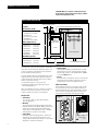
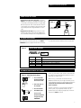
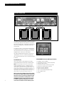
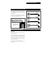
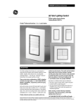
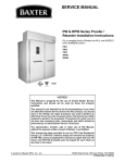
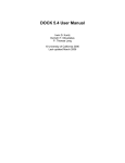
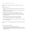
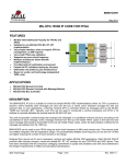
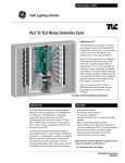
DEH40212 Installation Instructions
GE Total Lighting Control
ProSys Lighting Control System
Catalog Number RINTERxxxPS(P)
ProSys™ Lighting Control System Relay Panels
RINTER2424PSP 24-Relay Interior shown with RTUB24
DESCRIPTION
The ProSys Lighting Control System is a small network of
relay panels and occupant control switches linked by a 4-wire
dataline. Together, these devices form a reconfigurable
switching platform — one that uses “softwiring” instead of
hardwiring to link occupant switches to relays. Scheduling
capability can be readily added by simply mounting an
RCLK8PS Softwired Clock to the DIN rail in any relay panel.
The RINTERxxxxPS(P) 1 is the interior for a ProSys
Lighting Control System Relay Panel. The complete relay
panel assembly will include the following:
1.
2.
3.
4.
Tub (RTUBxx)
Interior (RINTERxxxxPS or RINTERxxxxPSP)
Power Supply (RPWRxxx)
Cover (RCOVxxxx)
This instruction sheet will show you how to:
1. Install the Relay Panel(s)
2. Install and Test the Dataline
3. Document the Relay Panels
Full descriptions of the installation and operation of Softwired
Switches and the Softwired Clock and other optional
automation devices are located in other sections of this
manual and are provided with each hardware unit.
Before starting, read the following installation
instructions. If you have questions, call GE Total
Lighting Control Service at:
1-877-584-2685 (LTG-CNTL) in the USA and Canada.
These instructions do not cover all details or variations in equipment nor do they provide for every possible contingency that may be met in connection with
installation, operation or maintenance. Should further information be desired or should particular problems arise that are not covered for the purchaser's purposes,
the matter should be referred to the GE Company.
1
DEH40212 Installation Instructions
CAUTION: Make sure all power is OFF before wiring.
Do not energize wiring until the unit is fully assembled.
Conform to all applicable codes.
RELAY PANEL INSTALLATION
SWITCHED LIGHTING CIRCUITS
Figure 1
1.5" x 1.5" CROSSOVER WIRING CHANNEL (TOP AND BOTTOM)
2" TYP.
Dimensions (A x B)
RINTER1212PS(P)
16.0" (406mm) x 16.5" (419mm)
RINTER2424PS(P)
22.5" (572mm) x 24.0" (610mm)
RINTER4848PS(P)
36.0" (914mm) x 24.0" (610mm)
RELAYS
Relay Capacities (C)
RINTER1212PS
RINTER1212PSP
12 RR7 relays
12 RR9 relays
RINTER2424PS
RINTER2424PSP
24 RR7 relays
24 RR9 relays
RINTER4848PS
RINTER4848PSP
48 RR7 relays
48 RR9 relays
CLASS 2
LOW-VOLTAGE
WIRING SECTION
RELAYS
A
C
C
DIN RAIL
CIRCUIT BREAKER PANEL
DIN Rail Capacities
RINTER1212PS(P)
One module
RINTER2424PS(P)
Two modules
RINTER4848PS(P)
Two modules
4.5" D
LINE-VOLTAGE WIRING SECTIONS
5" WIDE
If you have purchased the ProSys II Lighting Control System
(the stand-alone system), the devices (panels, switches and
clock) will be in self-install mode, which means that as soon
as they are connected to the network, they are operational
and can communicate with each other.
If you have purchased the ProSys LM Lighting Control System
along with the ProSys LM software, the devices will be in
software-install mode. This means that in order for them to
function on the network you must:
• assign network addresses to the devices and
• bind network variables and message tags using your
network management tool.
Addresses and binding are necessary for the devices to function on
the network. ProSys LM users please refer to the ProSys LM
Software User Guide for instructions on installing devices.
Rough-In Tub
• Environment
32 to 131oF (0 to 50 oC), 0 to 95% relative humidity,
stationary applications
• Mounting
The tub should be level, plumb and rigidly installed with
hardware sufficient to hold 100 lbs. (48kg). For flush-mount
panels, the front flange should be flush with the final
finished surface. For multiple panels, allow 1⁄4” minimum
between panels for showbox cover clearance.
• Pulling Wires
Route line-voltage wiring through the 2 1⁄2” knockouts in
either the top or bottom of the tub. Route Class 2 lowvoltage dataline from the remote switches or other controls
through the 3⁄4” knockouts in either end.
2
B
ILLUSTRATION NOT TO SCALE
Install Interior
• Power Supply
Attach the power supply to the frame (bottom of 12-relay
interior and left side of 24- or 48-relay interiors) and plug
the low-voltage connector to the terminal marked “POWER”
as shown in Figure 1 above.
• Interior
Mount the interior in the tub and secure it to the studs with
the hardware provided. Make sure that all line- and lowvoltage wiring is confined to the appropriate areas.
Wire Line Voltage
Before making any connections to the relays, make sure that
none of the load circuits are shorted. Wire from the circuit
breaker through each relay’s SPST output terminals, and from
there to the loads. Confirm that each circuit is wired to the
relay specified in the drawings. Wire the power supply.
Figure 2
115 NEU GRD
VAC
J2
GE Lighting Controls
RINTER2424PS
shown
DEH40212 Installation Instructions
POWER UP AND TEST RELAYS
1. Apply power to the power supply only. As shown in
Figure 3, to the right, press the Relay Control Button next
to each relay’s yellow plug-in termination to toggle it ON/
OFF. The relay should “click” and the LED status indicator
should change state. Confirm the operation by measuring
the continuity at the line-voltage terminations of each
relay.
2. Apply power to the relays. Being careful not to touch
any line-voltage wiring, toggle each relay ON/OFF again
and confirm that each relay controls the appropriate load.
Figure 3
TO RELAY
RR7P RELAY SHOWN
LED INDICATOR
RELAY
CONTROL
BUTTON
DOCUMENT RELAY WIRING
Record the circuit controlled by each relay on the RELAY
SCHEDULE which was shipped with the interior. The relays
Figure 4
associated with automation channels A-H are recorded later.
PROSYS RELAY SCHEDULE
PANEL # 01
RELAY #
-01
-02
-03
-04
-05
SUPPLY
LP1-1
LP1-2
LP1-3
LP1-4
LP1-5
LOAD DESCRIPTION
OPEN OFFICE - FIRST FLOOR NW
"
OPEN OFFICE - FIRST FLOOR NE
"
OPEN OFFICE - FIRST FLOOR SW
SOFTWIRING A RELAY GROUP TO A CHANNEL
Figure 5 – Softwiring a Relay Group
H
H
FLASHING
RED LED
PRESS
AND
HOLD
CHANNEL
PUSH
BUTTON
2
3
2 Select the relays to
be controlled.
FLASHING
LED
H
H
1 Press and hold the
Channel Push Button
for several seconds.
3 Press the Channel
Push Button again.
Each ProSys panel includes eight “channels” (A-H) which may
be softwired to relays within the panel. Channels are used to
group relays for common control.
When a ProSys system includes an automation module
(RCLK8PS Softwired Clock), we strongly recommend you turn
to the installation instructions for that automation module and
complete the documentation before softwiring any
relays to channels.
However, if automation is to be provided by an interface to
another system, or by using manual switches only, the
channels may be used simply for grouping relays. Follow the
instructions in Figure 5 to the left.
Test. Press the
Channel Push Button
to toggle the group
ON/OFF/ON.
3
DEH40212 Installation Instructions
DATALINE INSTALLATION
GLOBAL (PANEL-TO-PANEL) DATALINE
PANEL 01
PANEL 02
PANEL XX
The dataline connects the relay panels, switches and optional
control modules. Within the 4-wire dataline are two twisted
pairs: the red and black wires, carrying data; and the blue and
white wires, providing power to the dataline switches and
control modules.
For simplicity, we refer to a 4-wire dataline running between
a relay panel and the dataline switches as a “Local Dataline”.
The relay panel provides the low-voltage power to all of the
intelligent devices on that section of the dataline.
The dataline running between relay panels is known as the
“Global Dataline,” and it uses only the red and black data
wires. The blue and white wires are not connected and should
be trimmed.
Panel Addressing
GE RLONWIREP-S4 Dataline Wire Specifications
The two rotary switches on each relay panel set its address,
allowing the differentiation between relays in different panels.
•
•
•
•
•
•
•
•
•
•
NOTE: The first panel address must be set at 01 and the others
numbered sequentially 02, 03, and so on, between 02 and 30 as
shown to the right. If the panel address is set higher than 30, the
channel LEDs in the panel will flash. Setting the panel address to 30
or below will return the panel to normal operation. If a panel is set to
the same address as another panel, then the two panels will not
operate properly. The ProSys LM panels can be setup in groups of 30
where the panels in a group can be numbered from 00 to 30.
4
Note: To ensure good communications between panels,
the installer must comply with the dataline specification.
GE will not warrant a system using a dataline that does
not meet our specification. To avoid questions, use GE
RLONWIRE-4P (plenum rated). Do not run the dataline
in conduit or wiring trays with power wires. Do not
connect the local datalines from two different panels.
#18 AWG (7 strands x 26 AWG)
2 independent twisted pairs – black/red, blue/white
Unshielded copper conductors
2 inch twist lay on pairs, 6 inch twist lay on cable
Plenum-rated copolymer jacket, 0.230" O.D.
FEP 0.010" insulation, 0.060" O.D.
30 pF/foot maximum capacitance
-20°C to 150°C operating temperature range
17 lbs. per 500 foot reel
UL rated
DEH40212 Installation Instructions
HARDWIRE LOW-VOLTAGE SWITCHES (OPTIONAL)
Each of the ProSys panel’s eight channels has a single switch
input which will accept any of the dry-contact configurations
shown in Figures 6 and 7, and also provides status feedback
for that channel.
ProSys panels whose catalog numbers end in “P” also include
inputs for each relay. Like the channel inputs, these support
all of the dry-contact configurations shown.
Figure 6 – Hardwired Switch Inputs
Figure 7 – Hardwired Switch Configurations
RED/BLACK JUMPER
MAINTAINED
ISOLATED CONTACT
R B Y W
BLACK/WHITE JUMPER
2-WIRE MOMENTARY
PUSH BUTTON
R B Y W
STANDARD 3-WIRE
MOMENTARY
R B Y W
STANDARD 3-WIRE
MAINTAINED
R B Y W
HARDWIRED CHANNEL SWITCHES
HARDWIRED RELAY SWITCHES*
* The ability to hardwire a 2- or 3-wire
switch directly to a relay is an option in
ProSys system panels. For panels with relay
inputs, order interiors with catalog
numbers ending in P.
PANEL TESTING AND TROUBLESHOOTING
Panel Testing
The panel-to-panel dataline should be tested for continuity
and isolation from ground.
To test for continuity, remove the red and black dataline wires
at panel 01 and wire nut together (short the wires together).
Go to the last panel in the series and measure the resistance
between the red and black terminals. It should be less than 3
ohms. Return to panel 01 and restore the red and black wires
to their associated terminals.
For shorts, test from red to white and black to white
anywhere in the low-voltage section of the panel. You should
see an open circuit.
5
DEH40212 Installation Instructions
GE Total Lighting Control
DEH40212 BL 0700 R02
6
GE Total Lighting Control
41 Woodford Avenue, Plainville, CT 06062
©2000 General Electric Company