1
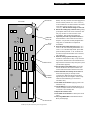
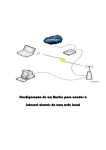
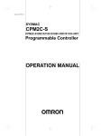
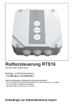
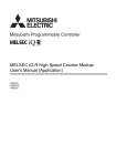
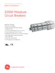
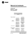
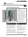
Catalog Number: RTR32
Total Lighting Controls
PLC To TLC Relay Controller Card
Upgrading to TLC
The RTR32 Relay Controller Card is an intelligent upgrade module for a GE Programmable
Lighting Control (PLC) panel. It provides a path
from PLC to the more fully-featured Total
Lighting Control (TLC) system architecture.
RELAY
NUMBER
1
RELAY
NUMBER
17
18
19
20
21
1
19
2
2
10
3
11
3
4
12
5
13
5
6
14
7
15
7
8
16
1
4
6
23
24
25
26
4
8
5
2
1
17
2
18
3
0
3
19
4
20
22
2
3
0
4
0
7
7
23
8
24
8
9
25
10
26
10
11
27
12
28
12
13
29
14
30
14
15
31
16
32
16
9
11
7
8
9
13
10
15
11
27
12
28
13
29
14
30
15
31
32
HIGH
ADDRESS #
Most older GE systems fall into two categories:
ETA panels with an ECON Controller, or SRC
panels with no central controller. (Refer to
“Upgrading PLC To TLC” on the next page for a
summary of system components.) To upgrade
these panels to TLC, simply replace the existing
Relay Controller and Switch Interface Cards with
the new RTR32 and RTS16 modules. Upgraded
panels can coexist with older panels until the
whole system is converted to TLC.
5
6
5
21
6
22
6
16
230
270
347
VAC
115
VAC
HIGH
ADDRESS #
Note: The original type of PLC system, a
BCON Controller with BTA panels, can also
be upgraded using an additional kit, the
RTLCCAN.
GRD
HOT
NUET
GE SELECTOR
NOTE: SET VOLTA
GE INPUT
TO PROPER VOLTA
ETA PANEL WITH RTR32 UPGRADE CARD INSTALLED
DESCRIPTION
The RTR32 Relay Controller Card replaces the ER16 or
ER32 card in an existing ETA panel, or the SRCM-R card
in an SRC panel. The motherboard in these panels
requires one relay controller card to provide full
monitoring and control for up to 32 relays. If an ES8,
ES16 or SRS16 switch interface card is also present in
the PLC panel, it must be upgraded to an RTS16 at the
same time as the RTR32.
The RTR32 gives ETA panels distributed intelligence,
eliminating the need for a central controller and allowing
the panels to run independently. In addition, all upgraded
panels will gain built-in lighting control scenarios and
advanced communications capabilities. The RTS16
provides programmable switch interfaces and works with
the RTR32 to provide full panel control and monitoring.
FEATURES
•
•
•
•
•
•
•
•
Simple plug-in modules.
No rewiring of relays necessary.
32-relay control capability.
Used with the RTS16, up to 16 global switch inputs
available.
Built-in programmable lighting scenarios.
Indirect relay switching. Each relay in the panel can
only be controlled by the RTR32. There are no landing
points for local switches or occupancy sensors.
Runtime and status information for all relays.
Memory backup during power outages.
Before starting, read the installation instructions inside.
If you have questions call GE Service at:
1-877-584-2685 (USA) and (Canada)
Installation Instructions
IMRTR32
Catalog Number: RTR32
CAUTION: The power supply must be OFF when
inserting or removing cards. These instructions
assume the panel has a standard cover which exposes
both line voltage and low voltage sections. The line
voltage sections must be covered to avoid exposure to
live high voltage wiring.
If an SRC system is being upgraded, DO NOT CONNECT
THE DATALINE UNTIL AFTER ALL THE PANELS HAVE
BEEN UPGRADED. SRC modules will fail if connected
to the dataline.
MOTHERBOARD
DATA LINE
WHT
RED
BLK
WHT
RED
BLK
WHT
RED
BLK
WHT
RED
BLK
BLU
RED
BLK
BLU
RED
BLK
BLU
RED
BLK
BLU
RED
BLK
BLU
RED
BLK
BLU
RED
BLK
BLU
RED
BLK
BLU
RED
BLK
BLU
RED
BLK
BLU
RED
BLK
BLU
RED
BLK
BLU
RED
BLK
BLU
RED
BLK
BLU
RED
BLK
BLU
RED
BLK
BLU
J2
1
2
2
1
J3
LOWER ADDRESS SWITCH INPUT
WHT
BLK
ASSY 483C184G
BLK
RED
+
COM
G.E. OPTIONS ONLY
RED
RELAY MODULE CONNECTOR
WHT
+
WHT
BLK
AUX.
CONNECTIONS
GREY/WHITE
LABEL STRIP
(see Step #9)
BLK
RED
GENERAL ELECTRIC MOTHERBOARD
437D393
HIGH ADDRESS RELAYS (32 RELAY ASSY. ONLY)
25
RED
-RESET
LOWER ADDRESS RELAY OUTPUT
16
WHT
HIGH ADDRESS SWITCH INPUT
(16 SW. ONLY)
19
10
2
11
3
12
4
13
5
14
6
15
7
8
1
17
18
2
19
3
20
4
21
5
22
6
23
7
24
8
9
26
10
27
11
28
12
29
13
30
14
31
15
32
16
BLK
SWITCH MODULE CONNECTOR
+RESET
RED
–
–
+
+
SHLD
RED
BLK
WHT
RED
BLK
WHT
RED
BLK
WHT
RED
BLK
WHT
RED
BLK
WHT
RED
BLK
WHT
RED
BLK
WHT
RED
BLK
WHT 8
RED
BLK
BLU
RED
BLK
BLU
RED
BLK
BLU
RED
BLK
BLU
RED
BLK
BLU
RED
BLK
BLU
RED
BLK
BLU
RED
BLK
BLU
RED
BLK
BLU 9
RED
BLK
BLU
RED
BLK
BLU
RED
BLK
BLU
RED
BLK
BLU
RED
BLK
BLU
RED
BLK
BLU
RED
BLK
BLU
J3
GENERAL ELECTRIC CO. COPYRIGHT 1983
REV A
Steps for Upgrading to TLC
1. If you have a BTA/BCON system, install the RTLCCAN
kit.
2. For all systems, next install the RTR32 Relay
Controller Card.
3. If switch interfaces are required, next install the
RTS16 Switch Interface Card.
Installing the RTR32
SHLD
POWER SUPPLY
INSTALLATION
1
2
3
4
5
6
7
8
1
2
3
4
5
6
7
8
9
10
11
12
13
14
15
16
These instructions repeat several of the steps involved
in the RTLCCAN installation. If you have just installed
the RTLCCAN and have not yet reapplied power, skip to
Step #7. Power must be OFF.
1. Program the system. Before replacing any cards, you
should set up the new system program using TLC
system software RSOFT-CM1. Upgraded panels must
receive an initial program from RSOFT in order to
work. To minimize downtime for your lighting control
system, please document your site wiring and
prepare the RSOFT program for your site before
physically changing any hardware. Refer to the
RSOFT User’s Manual supplied with the software.
2. Turn OFF the circuit breakers supplying line voltage
to all relays and the transformer in the panel.
3. Remove the panel cover.
4. Test the transformer terminals with a voltmeter to
ensure power is OFF. ( A red LED should be ON when
power is ON, and OFF when power is OFF. However,
for complete safety, check with a voltmeter).
5. Examine the panel interior to identify the motherboard (shown left), relay controller card (ER16, ER32
or SRCM-R) and switch interface card (ES8, ES16 or
UPGRADING PLC TO TLC
The following chart is designed to help you identify the components of your existing GE Programmable Lighting Control
system, and the new components required to upgrade to Total Lighting Control.
Controller
Panels
Relay Controller Card
Switch Interface Card
Dataline
To Upgrade to TLC
B-GENERATION
BCON
BTA
Built-in
Built-in
Yes
Replace panel interior
with TLCCAN.
Install RTR32 and
RTS16 cards.
E-GENERATION
ECON
ETA
ER16 or ER32
ES8 or ES16
Yes
Replace relay card
with RTR32.
Replace switch card
with RTS16.
SRC
SRRP-xx in each panel
SRSP
SRCM-R
SRS16
No
Replace relay card
with RTR32.
Replace switch card
with RTS16.
Install a dataline if
multiple panels are to be
networked.
Catalog Number: RTR32
EJECTOR TAB
TOP OF CARD
RTR32
HARDWARE
STATUS LED
RELAY
STATUS LED*
CARD CONNECTOR
RESET SWITCH
ADDRESS
SET KNOBS
EJECTOR TAB
BOTTOM OF CARD
*All OFF/any relay ON. When flashing, card is unprogrammed.
SRS16). The relay controller card will be plugged into
the left connector (marked “RELAY MODULE CONNECTOR”)
on the motherboard. The switch interface card will be
in the right connector (marked “SWITCH MODULE
CONNECTOR”). Note the address settings on each card.
6. Remove the existing relay controller card by pulling
up the Ejector Tabs on the corners of the board. This
will “pop” the card out of the connector on the
motherboard. Then pull the card straight out.
7. Inspect the pins in the relay module connector on
the motherboard to ensure there are no broken or
bent pins. If any are bent, carefully straighten them
using pliers, or call GE Service to replace the
motherboard.
8. Place the supplied white label strip marked “RELAY
NUMBER 17-32” over the existing label marked “RELAY
NUMBER 1-16” on the LEFT relay barrier. (Some SRC
panels are already marked “17-32” on the left side
and will not require the new label. If this is the case,
skip to Step #10.)
9. Snake the small grey/white label strip (gray for
switches 9-16 and white for relays 17-32) under the
relay wires on the LEFT side of the motherboard so it
aligns with the switches and relays and press in place
(see illustration opposite).
10. Set the address of the RTR32 card by turning the
Address Set Knobs to the required numbers. You
should set the same address that the old card had.
11. Slide the RTR32 card vertically into its slots until
the module rests gently on the relay module
connector pins. Make sure the pins are properly
aligned and push the card straight in until it is fully
seated on the motherboard (you should feel a
noticeable “click”).
12. Turn ON the circuit breaker supplying power to the
transformer only.
13. Test the RTR32 by pressing the Reset Switch for 10
seconds. All relays should come ON. Press again for
10 seconds to turn all relays OFF.
14. Replace the enclosure cover.
15. Turn ON the circuit breakers to restore power to the
relays.
16. Test, using RSOFT-CM1 in Panel Monitor/Control
Mode (see back page).
Catalog Number: RTR32
EMERGENCY SERVICE OR SUPPORT:
1-877-584-2685 (USA) and (Canada)
TESTING THE UPGRADED LIGHTING CONTROL SYSTEM WITH RSOFT-CM1
Refer to the TLC RSOFT-CM1 Operating Software User’s
Manual, Part 5, Monitor/Control. To confirm that the
RTR32 card is properly controlling relays in a Lighting
Automation Panel (LAP), use RSOFT-CM1 in the Monitor/
Control LAP Mode.
1. If your computer is not currently connected, select
the “Connect” option to connect to the LAP or LINK
device.
2. From the Main Menu, select “Monitor and Control”.
3. From the Monitor and Control Menu, select “Monitor/
Control LAP”.
4. Enter the Panel Number you wish to monitor.
5. Pressing the Space Bar will toggle the display format
to one that provides more detail about each relay.
6. Use Page Down to check the state of all the relays in
the panel (ON or OFF).
If the panel is not responding, a message will appear on
screen. Call GE Service at one of the numbers above.
DOCUMENTING THE SITE WIRING
In a networked lighting control system, each relay panel
must have a unique address number. For TLC upgrades,
this is set by the Address Set Knobs on the RTR32 Relay
Controller Card and the RTS16 Switch Interface Card.
Why do relay and switch input numbers change when
PLC is upgraded to TLC?
In PLC panels, relays were set up in groups of 16 (and
switch inputs in groups of 8) as shown in Figure 1. The
first 16 relays (and 8 switch inputs) were installed on the
RIGHT side of the panel and numbered 1-16 (1-8). Panel
addresses were usually assigned as EVEN numbers
(Panel #002, #004, etc.). If a panel included another 16
relays (for a total of 32), and another 8 switch inputs (for
a total of 16), they were installed on the LEFT side of the
panel, but still numbered 1-16 (1-8). This second group
of relays and switch inputs was considered another
panel, and was assigned the next higher ODD number
panel address. So a single tub could include two panel
addresses — Panel #002 for the RIGHT side and Panel
#003 for the LEFT side.
When PLC panels are upgraded to TLC, they can still
have up to 32 relays and 16 switch inputs, but only one
panel address (which can be either odd or even) as
shown in Figure 2. Relays are numbered 1-16 on the
RIGHT side and 17-32 on the LEFT side. Switch inputs
are numbered 1-8 on the RIGHT side and 9-16 on the
LEFT side. Label strips are supplied with the RTR32
upgrade kit to identify the new numbering scheme (see
Steps #8 and #9 on the previous page).
When documenting your site wiring and entering this
information in RSOFT, review the panel addresses to
ensure there are no duplicates. Remember that panels
now have one address for both right and left sides, and
relays are now numbered 1-32 and switch inputs 1-16.
Figure 1: PLC Panel
1 PANEL #003
SWITCH
8 INPUTS
PANEL #002 1
SWITCH
INPUTS 8
PANEL #003 PANEL #002
1
PANEL #003
RELAYS
1
PANEL #002
RELAYS
16
16
Figure 2: PLC Panel Upgraded To TLC
9
1
PANEL SWITCH INPUTS
16
8
PANEL #002 (or #003)
17
1
PANEL RELAYS
32
16
TROUBLESHOOTING
If no relays respond to the reset test in Step #13 on the
previous page, check the RTR32 Hardware Status LED
with the low voltage power supply ON.
If the LED is OFF, power is not flowing to the card. Turn
OFF the low-voltage power supply and reseat the card.
If the LED is flashing, the card is defective. Call the
emergency number shown on the back page.
GE Lighting Controls, 41 Woodford Ave., Plainville, CT 06062
Made in U.S.A.