1
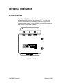
GE Energy Management TM Maintenance Action Planner LTC-MAP 2130 Monitor Product Manual Part No. 70055MP Rev. D, February 3, 2000 GE Energy Management LTC-MAP 2130 Monitor Maintenance Action Planner Monitoring System Product Manual 70055MP Revision D February 3, 2000 Copyright Information Copyright 2000 Reuter-Stokes, Inc. All rights reserved. This manual may not, in whole or part, be copied, photocopied, reproduced, translated or reduced to any electronic medium or machine readable form without prior consent, in writing, from Reuter-Stokes, Inc. The illustrations shown in this manual are intended solely to illustrate the text of this manual. Because of the many variables and requirements associated with any particular installation, Reuter-Stokes, Inc. cannot assume responsibility or liability for actual use based upon the illustrative uses and applications. Trademarks LTC-MAP™, SAGE™, are trademarks of Reuter-Stokes, Inc. Warranty Reuter-Stokes, Inc. warrants each of our products to be free from defects in material or workmanship. Our obligation under this warranty is to repair or replace, at our discretion, any product or part of a product that proves to be defective upon examination within 18 months of the date of shipment, or 12 months from the date of startup, whichever occurs first. No other warranty is expressed or implied. Reuter-Stokes, Inc. does not warrant that your monitoring system will operate as described in this manual in every environment. Reuter-Stokes, Inc. has thoroughly tested the equipment and reviewed the documentation. However, Reuter-Stokes, Inc. does not warrant the performance of the products for for any particular purpose. In no event is Reuter-Stokes, Inc. liable for any damage resulting, directly or indirectly, from the use of this product. THE EXPRESS WARRANTY SET FORTH ABOVE IS EXCLUSIVE, AND NO OTHER WARRANTY OF ANY KIND, WHETHER STATUTORY, WRITTEN, ORAL, EXPRESS, OR IMPLIED (INCLUDING WARRANTIES OF FITNESS FOR PARTICULAR PURPOSE OR MERCHANTABILITY), SHALL APPLY. Revision History Revision 1.0 1.1 B C D February 3, 2000 Release Date November 14, 1997 January 26, 1998 July 6, 1998, July 19,1999 October 14, 1999 February 3, 2000 ii 70055MP Revision D Table of Contents Section 1: Introduction Product Overview...................................................................................................................................................... 1-1 Specifications ........................................................................................................................................................... 1-3 Input................................................................................................................................................................... 1-3 General............................................................................................................................................................... 1-4 Electrical ........................................................................................................................................................... 1-5 Environmental................................................................................................................................................... 1-5 Physical Enclosure.......................................................................................................................................... 1-5 Available Options...................................................................................................................................................... 1-6 Typical Application .................................................................................................................................................. 1-7 Manual Conventions ................................................................................................................................................ 1-9 Product Labels .......................................................................................................................................................... 1-9 Section 2: Getting Started Receiving Inspection................................................................................................................................................ 2-1 Customer Support/Service....................................................................................................................................... 2-1 Front Cover Layout.................................................................................................................................................... 2-2 Face Panel Layout .................................................................................................................................................... 2-3 Operating Conditions Button ............................................................................................................................. 2-4 Alarm Status & Settings Button......................................................................................................................... 2-4 Acknowledge Alarm Button................................................................................................................................ 2-4 LCD Display ........................................................................................................................................................... 2-5 Serial Port .............................................................................................................................................................. 2-5 Circuit Board Location............................................................................................................................................. 2-6 I/O Board ............................................................................................................................................................... 2-7 Power Supply Board ............................................................................................................................................ 2-8 CPU Board ............................................................................................................................................................. 2-9 Communications ..................................................................................................................................................... 2-10 Section 3: Installation Selecting a Location ................................................................................................................................................ 3-1 Mounting the Monitor.............................................................................................................................................. 3-2 Cable Installation...................................................................................................................................................... 3-3 I/O Board Configuration Jumpers .......................................................................................................................... 3-4 Channel Configuration ........................................................................................................................................ 3-4 Modem Power Supply Configuration Jumper.................................................................................................. 3-5 Alarm Configuration Jumpers ............................................................................................................................ 3-6 Ground Jumpers ................................................................................................................................................... 3-6 Wiring ......................................................................................................................................................................... 3-7 Overview................................................................................................................................................................. 3-7 Wiring the Sensors............................................................................................................................................. 3-10 Wiring a Tap Position Indicator...................................................................................................................... 3-11 OEM Potentiometers ...................................................................................................................................... 3-11 After-Market.................................................................................................................................................... 3-16 Wiring the AC Voltage Inputs........................................................................................................................... 3-17 Wiring the AC Current Inputs ........................................................................................................................... 3-17 Wiring the Digital Inputs................................................................................................................................... 3-17 Wiring the Annunciator Outputs ..................................................................................................................... 3-18 Wiring the Internal Heater ................................................................................................................................ 3-19 Wiring Power....................................................................................................................................................... 3-19 70055MP Revision D iii February 3, 2000 Establishing Communications.............................................................................................................................. 3-20 Serial Port Communications ............................................................................................................................. 3-21 Modem Communications .................................................................................................................................. 3-22 Initial Start Up ......................................................................................................................................................... 3-23 Calibrate Tap Position............................................................................................................................................ 3-24 Section 4: Operation Overview ..................................................................................................................................................................... 4-1 Operating Conditions Button.................................................................................................................................. 4-1 Analog Channel Readings Screens................................................................................................................... 4-2 Digital Channel Readings Screens .................................................................................................................... 4-2 Tap Change Summary Screen ............................................................................................................................ 4-3 Alarm Status & Settings Button ............................................................................................................................. 4-5 LTC-MAP Status Screen ...................................................................................................................................... 4-5 Current Time and Date Screen............................................................................................................................ 4-6 Acknowledging Alarms ............................................................................................................................................ 4-6 Section 5: Troubleshooting Procedures Appendix A: User-Specific Information Forms Appendix B: Firmware Upgrades Appendix C: Glossary of Terms Index February 3, 2000 iv 70055MP Revision D Section 1: Introduction Product Overview The LTC-MAP 2130 Monitor (Figure 1-1) is an on-line maintenance action planner (MAP) for load tap changers (LTC). It continuously monitors performance data from various types of sensors, such as temperature and current. It stores this data in non-volatile memory for downloading to a personal computer. Figure 1-1: LTC-MAP 2130 Monitor 70055MP Revision D February 3, 2000 1-2 Section 1: Introduction LTC-MAP 2130 Monitor is a multi-input data storage and analysis system. Each system features: • • • • Seventeen (17) analog input channels. Sixteen (16) digital input channels (via optional Control Isolator). One (1) serial port/modem line. Two annunciator relay outputs (form C contacts). LTC-MAP 2130 uses state of the art technology to process, analyze, and store data into a configurable profile. A built-in microprocessor compares, computes, and relates stored data to set parameters. Alarms are generated when data levels exceed the set parameters. NOTE: Parameters are set via the SAGE host software package. Refer to the SAGE Product Manual, Part No. 70057MP, for details on parameter configuration and data retrieval and analysis. Data profiles and alarm events are stored in non-volatile randomaccess memory. The stored information is then downloaded to a personal computer, either directly through the serial port or via an optional modem. The SAGE host software package allows data retrieval and analysis. February 3, 2000 70055MP Revision D Section 1: Introduction 1-3 Specifications Input Analog Seventeen (17) channels. Channels 1 - 7 Input: 4 to 20 mA. Sample rate: 150 Hz. Channel 8 Input: ±10 VDC. Sample rate: 150 Hz. Channels 9-11 Configurable input: • 4 to 20 mA with a sample rate of 150 Hz, or • 5A AC (as monitored by a CT) with a sample rate of 1920 Hz. Channel 12 Configurable input: • 4 to 20 mA with a sample rate of 150 Hz, or • 50A AC (as monitored by a CT) with a sample rate of 1920 Hz. Channels 13-16 Configurable input: • 4 to 20 mA with a sample rate of 150 Hz, or • 120/240 VAC with a sample rate of 1920 Hz. Channel 17 Configurable input: • 4 to 20 mA with a sample rate of 150 Hz, or • Signal conditioned with a sample rate of 1920 Hz. Digital 70055MP Revision D Sixteen channels via two optional control isolators (eight channels each). Input: ±120/240 VAC. Sample rate: 960z. February 3, 2000 1-4 Section 1: Introduction General Relay Outputs Front Panel Indicators Display Two dry-contact relay outputs for alarm indication. Three LEDs: POWER: When lit, indicates that the monitor is receiving power. ALARM1: When lit, indicates that a software configurable alarm has been activated; contact relay driven. ALARM2: When lit, indicates that a software configurable alarm has been activated; contact relay driven. Front panel four line liquid crystal (LCD). Resolution: 1 V, 1 A, 1 °C. Communications Standard: RS-232-C serial port; DB-9 connector. Optional: 14.4k bps modem, installed on the back left side of the monitor base. Data Storage Type: Non-volatile, solid state RAM. Capacity: Up to 128 K, based on configuration. Mode: Revolving loop. Averaging Interval: Configurable from 1 to 60 minutes. Controls Three front panel push buttons: Operating Conditions: Used to display present operating conditions. Alarm Status & Settings: Used to display present alarm status. Acknowledge Alarm: Used to deactivate alarm relays. One CPU Board mounted push button: SETUP: Used to initiate setup procedure for tap position calibrations. Installation Category Maintenance Cleaning Intermittent Operation February 3, 2000 III. No regular maintenance is required. No regular cleaning is required. No specific limit; however, intermittent operation is undesirable and should be corrected as soon as possible. 70055MP Revision D Section 1: Introduction 1-5 Electrical Sensor Power Supply Power Input Protection Power Input (Electrical Rating) 24 VDC @ 0.65A. Fused (F1) Type: AGC3 instant blow. Rating: 3A @ 250 V. AC: Standard: 120 VAC +10/-15%AC, 50 - 60 Hz. Optional (factory set): 240 VAC +10/-15%AC, 50 - 60 Hz. DC: 125 VDC +15%DC. NOTE: Monitors supplied with internal heater option must have AC power input. Power Consumption Supply Voltage Fluctuation Less than 16VA. Mains supply voltage must not exceed +10% of nominal supply voltage. Environmental Operating Temperature Range Pollution Degree Standard: 0°C to +60 °C (+32°F to +140 °F). With Heater Option: -40°C to +60 °C (-40°F to +140 °F). 4. Maximum Relative Humidity 80%. Maximum Altitude 2000m. Physical Enclosure Material Stainless steel, weather-proof. Standard NEMA Type 4. Dimensions Weight 12” (305 mm) x 12” (305 mm) x 6” (152 mm). 18 lbs. (8.16 kg); additional weight for accessories. NOTE: Specifications subject to change without notice. 70055MP Revision D February 3, 2000 1-6 Section 1: Introduction Available Options Available options for the LTC-MAP 2130 are listed in Table 1-1. Refer to the applicable documentation for detailed information on the available options. Table 1-1: LTC-MAP 2130 Options Option Magnetic Mount RTD Temperature Sensor Part No. 30000MP RTD Transmitter T821028 Clamp-On AC Current (CT) Sensor T821026 Control Isolator 40041MP Combustible Gas Sensor 10384MP Moisture Sensor T801074 Eight Line Phone Multiplexer 40047MPA Fifteen Line Phone Multiplexer 40047MPB 14.4k bps Modem 20046MP SAGE Host Software Package SAGE February 3, 2000 Description/Function Attaches magnetically to the transformer; has a built-in 4-20 ma transmitter. Refer to Document No. 70063MP for more information. Connects to an insertion-type temperature sensor and transmits a 4-20 mA signal back to the monitor. Refer to Document No. 70064MP for more information. Clips onto a transformer lead and detects load current. Refer to Document No. 70059MP for more information. Optically isolates the monitoring system from the transformer controls. Refer to Document No. 70062MP for more information. Measures hydrogen and hydrocarbon levels in the insulating oil. Measures moisture levels in the insulating oil. Refer to Document No. 70065MP for more information. Allows up to eight monitors (with installed modems) to be connected to a single phone line for data transmission. Refer to Document No. 70061MP for more information. Allows up to fifteen monitors (with installed modems) to be connected to a single phone line for data transmission. Refer to Document No. 70061MP for more information. Installed in the monitor; allows transfer of data and configuration parameters over a telephone line to an off-site PC. Refer to Document No. 70058MP for more information. Provides tools for parameter configuration, parameter calibration, data retrieval, and data analysis. Refer to Document No. 70057MP for more information. 70055MP Revision D Section 1: Introduction 1-7 Typical Application A transformer utilizing an LTC-MAP 2130 monitor is illustrated in Figure 1-2. The monitor is mounted on the transformer. Analog sensors mounted on the transformer are connected to the monitor. Refer to the example typical wiring diagram in Section 3 to determine specific sensor input connections. Figure 1-2: Typical LTC-MAP 2130 Application 70055MP Revision D February 3, 2000 1-8 Section 1: Introduction A typical system may include several monitors, one for each transformer at the site, multiplexed together. The multiplexer is typically located at the on-site substation. (See Figure 1-3). Data from all monitors on site may then be downloaded to a remote personal computer (PC). SAGE host software installed on the PC allows for data retrieval and analysis. Figure 1-3: Typical System February 3, 2000 70055MP Revision D Section 1: Introduction 1-9 Manual Conventions This manual provides the information you will need to install, operate, and maintain the LTC-MAP 2130 Monitor. Throughout this manual CAUTIONS, WARNINGS, and NOTES are provided. CAUTION: Indicates a potentially hazardous situation which, if not avoided, may result in minor or moderate injury. WARNING: Indicates a potentially hazardous situation which, if not avoided, may result in death or serious injury. NOTE: Contains supplemental information. 70055MP Revision D February 3, 2000 Section 2: Getting Started Receiving Inspection On receipt of the LTC-MAP 2130 Monitor: 1. Carefully inspect the packing containers and contents for physical damage. 2. Carefully unpack the monitor, checking that all items listed on the packing slip are present and in good condition. NOTE: If damage is evident, or any items are missing, contact Support Services at (330-425-3755) for further instructions. Customer Support/Service For service or support for your LTC-MAP 2130 Monitor, contact: Field Service/Customer Support Department Reuter-Stokes, Inc. GE Syprotec Edison Park 179 Boulevard Brunswick 8499 Darrow Rd. Pointe-Claire, Quebec H9R 5N2 Twinsburg, OH 44087 Canada PH: 330-425-3755 PH: 514-694-3637 FAX: 330-425-1812 FAX: 514-694-9245 www.gepower.com 70055MP Revision D February 3, 2000 2-2 Section 2: Getting Started Front Cover Layout There are three indicator lights on the front cover of the LTC-MAP 2130 Monitor (see Figure 2-1): • The yellow POWER indicator illuminates whenever the monitor is receiving power. • The red ALARM1 indicator illuminates whenever a configured contact relay alarm is activated. • The red ALARM2 indicator illuminates whenever a configured contact relay alarm is activated. The fasteners on the right side of the front cover allow access to the inside face panel of the monitor. Figure 2-1: LTC-MAP 2130 Monitor (Front Cover) February 3, 2000 70055MP Revision D Section 2: Getting Started 2-3 Face Panel Layout The face panel is accessed by releasing the fasteners on the right side of the front cover. The front panel features (see Figure 2-2): • A four-line LCD display. • Operating Conditions button. • Alarm Status & Settings button. • Acknowledge Alarm button. • A serial port. Present operating conditions, alarm settings, and alarm status may be viewed on the display by pressing the appropriate buttons. The serial port allows direct connection, utilizing a null modem cable, between the LTC-MAP 2130 and a portable computer for data transfer. NOTE: A null modem cable is available from Reuter-Stokes (Part No. 10101MP). The two thumb screws on the right side of the face panel provide access to the CPU and I/O circuit boards. Figure 2-2: LTC-MAP 2130 Monitor (Face Panel) 70055MP Revision D February 3, 2000 2-4 Section 2: Getting Started Operating Conditions Button The Operating Conditions button is located directly below and left aligned with the display. Pressing the Operating Conditions button displays the sensor value readings. Four channels are displayed simultaneously. The display includes: • Channel number. • Channel name. • Present reading. • Units. After all sensor screens are displayed, pressing the Operating Conditions button again displays the tap change summary screen. During tap position calibration, the Operating Conditions button is used to adjust settings. Alarm Status & Settings Button The Alarm Status & Settings button is located directly below and right aligned with the display. Pressing Alarm Status & Settings displays the monitor status and the date and time. If there are alarm conditions, pressing Alarm Status & Settings scrolls through descriptions of alarm conditions. During tap position calibration, the Alarm Status & Settings button is used to adjust settings. Acknowledge Alarm Button The Acknowledge Alarm button is located in the lower left corner of the face panel. Pressing Acknowledge Alarm resets the alarm relay; however, the indicator remains lit for the duration of the alarm condition. February 3, 2000 70055MP Revision D Section 2: Getting Started 2-5 LCD Display The LCD is a 20 character by 4 line display (Figure 2-3). It displays operating and status conditions. Screens are scrolled through using the Operating Conditions and Alarm Status & Settings buttons. L T C - MA P 2 1 3 0 r e v 2 1 3 0 . x x . y y c o p y r I g h t < Operating Conditions ( C ) 1 9 9 7 < Alarm Status & Settings Figure 2-3: Display with Control Buttons Serial Port CAUTION: The serial port and the modem cannot function simultaneously. When using the serial port for communications, the internal modem (if installed) must be disconnected at JP8; otherwise the serial port will not function. The serial port is a 9-pin male DB-9 connector. This port allows direct connection, utilizing a null modem cable, between the LTC-MAP 2130 and a portable computer for data transfer. Data transfer rate is 19.2 kbps. The serial port does not support dumb terminal operation. In order for communications to take place: • A null modem cable must be installed between the monitor serial port and personal computer serial port. • SAGE host software must be installed on the personal computer. NOTE: A null modem cable is available (Part No. 10101MP ). 70055MP Revision D February 3, 2000 2-6 Section 2: Getting Started Circuit Board Location The CPU and I/O circuit boards are accessed by loosening the two thumb screws on the right side of the face panel (see Figure 2-4). The CPU circuit board is mounted to the back side of the face panel. The I/O Circuit board is mounted to the inside rear panel of the Monitor cabinet. The Power Supply board is mounted on the I/O Circuit board. A ribbon cable connects the CPU and I/O circuit boards. Figure 2-4: LTC-MAP 2130 (Top View with Face Panel Open) February 3, 2000 70055MP Revision D Section 2: Getting Started 2-7 I/O Board The I/O Circuit board (Figure 2-5) contains sensor signal conditioning circuitry and hardware to interface to the sensors mounted on the transformer. Alarm #2 Jumper Alarm #1 Jumper C11 D10 R18 C10 TP1 U6 J1 RN6 J7 C4 J3 TP2 TP3 TP5 JP13 U2 RN1 R17 R15 C8 J2 U5 Power Jumper J17 J8 C16 RN2 U9 RN4 TP4 Q6 C34 U 1 R101 J6 D9 D28 R6 R64 C31 17 D31 R100 U13 D8 K3 C3 R68 C2 R67 U7 R70 1 15 CHANNEL 14 13 12 11 10 16 C12 9 A A R69 TP9 R3 C13 C32 TP7 TP6 U12 U11 TP8 C14 R102 Q4 Q2 D30 R24 B JP6 JP5 JP4 JP3 JP2 JP1 B JP9 JP7 JP8 C7 D11 C23 C24 R48 U10 C22 C17 C9 K2 Q1 R49 C18 R16 C15 U4 Sensor Ground Q5 C19 C33 C21 R20 D32 D29 Q3 U3 U14 J4 GT17 GT2 GT4 GT6 GT14 GT16 GT12 GT10 MODEM VOLTS 9V 6V GT8 R108 R109 OPEN=12V 16 6 15 5 14 4 13 3 12 2 11 A3 A2 Y EN +12 DIGITAL Sensor Inputs 9 ANALOG 1 ANALOG 2 Current Inputs C MOV6 C26 R99 D25 R98 T3 D24 MOV7 R97 B C28 D12 R92 A D16 T4 CURRENT J20 Outside Phone Line Connection VOLTAGE J19 INV K4 ANN2 NORM K1 Annunciator Inputs J12 U8 C6 J5 F1 Voltage Inputs C5 HEATER A 10 COM D1 D2 R7 R50 R53 R8 R12 T2 Q10 R112 NORM R113 LINE NEUT Z14 1 SENSOR POWER (24 VDC) R42 B MOV5 C25 J13 COM CURRENT C R39 R40 Z11 SENSOR COMMON 17 7 REL D18 D13 D14 T1 RJ1 VOLTAGE VOLTAGE VOLTAGE NC COM NO ANNUNCIATOR INPUT INPUT INPUT #2 #2 #3 #4 Z12 8 +12 GND J18 ANN1 VOLTAGE INPUT #1 Z10 R41 J16 RED GRN MOTOR PHONE R37 A J14 SENSOR INPUTS R43 Z8 B SENSOR INPUTS Z13 Control Isolator Inputs Y C C1 D4 D17 GT9 J15 COM 2ND CONTROL ISOLATOR Z9 GT11 R110 R111 NC COM NO ANNUNCIATOR #1 R38 GT13 J10 EN R44 GT15 SENSOR POWER (24 VDC) R71 GT7 COM 1ST CONTROL ISOLATOR C20 C27 GT5 SENSOR COMMON Ribbon Cable Connector (To CPU Board) GT3 Q9 Q7 INV MOV1 D3 C30 GT1 Q8 J9 Internal Modem Connection Figure 2-5: I/O Circuit Board 70055MP Revision D February 3, 2000 2-8 Section 2: Getting Started Power Supply Board The Power Supply circuit board (Figure 2-6) contains the low voltage supplies, incoming power terminals, and the power fuse (F1) for the monitor. F1 is a type AGC3 fuse, rated for 3 Amp at 250 V. Figure 2-6: Power Supply Circuit Board February 3, 2000 70055MP Revision D Section 2: Getting Started 2-9 CPU Board The CPU circuit board (Figure 2-7) contains the microprocessor (CPU), LCD Display, front panel buttons, and serial port. Figure 2-7: CPU Circuit Board 70055MP Revision D February 3, 2000 2-10 Section 2: Getting Started Communications The SAGE host software installed on a personal computer allows for data retrieval and analysis. Communications with the LTC-MAP 2130 must be established in order to download data to the PC or upload configuration information to the terminal. Communication between the PC and the monitor can be established: • Directly via the front panel serial port and a null modem cable to a personal computer running the SAGE host software. NOTE: SAGE host software must be installed on the PC for proper communication to take place. The front panel serial port does not support dumb terminal operation. • Over phone lines using an optional modem installed inside the monitor. • Over phone lines via a phone multiplexer installed in the control house and connected to several LTC-MAP 2130 monitors. Refer to Document No. 70061MP for detailed information on the phone multiplexers available from ReuterStokes, Inc. CAUTION: The serial port and the modem cannot function simultaneously. When using the serial port for communications, the internal modem (if installed) must be disconnected at J8; otherwise the serial port will not function. February 3, 2000 70055MP Revision D Section 3: Installation This Section includes procedures for installation, configuration, wiring, setting up communications, and initial start-up of the LTC-MAP 2130 Monitor. Selecting a Location The LTC-MAP 2130 is enclosed in a weatherproof stainless steel box that can be mounted indoors or outdoors. When selecting a mounting location for the monitor, verify that: • The mounting surface is able to support a minimum of 25 pounds (11.3 kg). • The mounting surface allows ample space for mounting the stainless steel box and allows for a 12-inch (305 mm) door clearance (see Figure 3-1). • Sensors are located nearby to minimize cable length. • Wiring and cables can access the monitor gland plate. • The face panel display is at a readable level. • An operating temperature of 0 ºC to +60 ºC (+32 ºF to +140 ºF) can be maintained at the monitor location. NOTE: With the heater option installed, an operating temperature of -40 ºC to +º60 C (-40 ºF to +140 ºF) must be maintained at the monitor location. CAUTION: Select a mounting location that assures an operating temperature of 0 ºC to +60 ºC (+32 ºF to +140 ºF), otherwise system operation could be interrupted. 70055MP Revision D February 3, 2000 3-2 Section 3: Installation Mounting the Monitor Secure the monitor to the selected location using four ¼-20# stainless steels bolts through the mounting holes (see Figure 3-1). ½" (12.7 mm) 8" (203 mm) 1/4-20 UNF (4PL.) 12" (305 mm) 14" (356 mm) 1 ½" (38.1 mm) ½" (12.7 mm) Front Door Clearance -- 12" (305 mm) Mounting Holes 8" (203 mm) Figure 3-1: LTC-MAP 2130 Monitor Mounting Dimensions February 3, 2000 70055MP Revision D Section 3: Installation 3-3 Cable Installation After securely mounting the LTC-MAP 2130 monitor, route the input and output cables back to the gland plate. CAUTION: Do not apply power to the LTC-MAP 2130 until all input and output cables are connected. The removable gland plate on the bottom of the LTC-MAP 2130 Monitor has pre-punched conduit holes (see Figure 3-2) and strain relief cable connectors. Weep holes are provided to allow drainage of excess moisture. Additional holes can be drilled into the gland plate if required. Remove the plate by removing the two nuts and washers securing it to the monitor. The nuts are accessed from inside the monitor. CAUTION: Do not drill additional holes into the gland plate while it is installed on the monitor. Metal chips can damage the circuit boards. 4.194" (106 mm) 1.25" (31.8 mm) .875" 22.2 mm 1" (25.4 mm) 10.25" (260 mm) Strain Relief Connector Weep Holes Figure 3-2: Gland Plate 70055MP Revision D February 3, 2000 3-4 Section 3: Installation I/O Board Configuration Jumpers The I/O board configuration jumpers allow you to customize the LTC-MAP 2130 monitor to your application’s specific sensor (channel type input), alarm, and modem requirements. Channel Configuration Channels 9 through 12 are configurable for a 4-20 mA sensor input or a 5A/50A current input (as monitored through a CT). Channels 13 through 16 are configurable for a 4-20 mA sensor input or a voltage input. Refer to Table 3-1 for specific jumper numbers and positions for each channel. Refer to Figure 3-3 for A and B jumper positions. Channel Configuration Jumpers JP13 J1 RN6 J7 J3 C4 TP2 TP3 C3 + JP13 RN1 J2 J8 U7 1 15 16 J17 U9 C2 + J6 U1 17 A B C1 + CHANNEL 14 13 12 11 10 JP9 JP7 JP8 JP6 JP5 JP4 JP3 JP2 Z1 C12 9 A JP1 C4 TP9 TP6 B J2 MOV1 J1 U2 C17 LINE NEUT POWER J.W.HARLEY INC. 20065MPA 20065MPB ASSY NO. U3 U14 GT4 GT6 GT14 GT16 GT12 GT10 GT8 MODEM VOLTS 9V 6V Q8 R108 R109 R110 OPEN = 12V C30 JP10 Q9 Q7 J18 R111 ANN1 INV R112 NORM R113 K4 D3 Q10 J19 INV K1 ANN2 NORM JP14 Modem Power Supply Configuration Jumper (JP12) Annunciator (Alarm) Configuration Jumpers (JP18 and JP19) Figure 3-3: I/O Board Configuration Jumper Locations February 3, 2000 70055MP Revision D Section 3: Installation 3-5 Table 3-1: Channel Configuration Jumpers and Positions Jumper JP1 JP2 JP3 JP4 JP5 JP6 JP7 JP8 JP9 Position A B A B A B A B A B A B A B A B A B Selected Input 5A (CT) Current Input A. 4-20 mA Sensor Input #9. 5A (CT) Current Input B. 4-20 mA Sensor Input #10. 5A (CT) Current Input C. 4-20 mA Sensor Input #11. 50 A (CT) Motor Current. 4-20 mA Sensor Input #12. Voltage Input 1. 4-20 mA Sensor Input #13. Voltage Input 2. 4-20 mA Sensor Input #14. Voltage Input 3. 4-20 mA Sensor Input #15. Voltage Input 4. 4-20 mA Sensor Input #16. Temperature Inside the monitor. 4-20 mA Sensor Input #1. Modem Power Supply Configuration Jumper Jumper JP12 sets the modem power supply. Refer to Table 3-2 for jumper positions. NOTE: Refer to the modem specifications to determine the modem power supply requirements. Refer to Figure 3-3 for jumper location. Table 3-2: Modem Power Supply Configuration (JP12) JP12 Position 1-2 2-3 No Jumper 70055MP Revision D Selected Modem Power Supply 6 VDC 9 VDC 12 VDC February 3, 2000 3-6 Section 3: Installation Alarm Configuration Jumpers Jumpers JP18 and JP19 set the annunciator relay outputs to normal or inverted. Jumper JP13 configures the Acknowledge Alarm button. Refer to Table 3-3 for jumper positions. Refer to Figure 3-3 for jumper locations. NOTE: JP13 must always be installed. Table 3-3: Alarm Configuration Jumper JP18 JP19 JP13 Position INV NORM INV NORM Installed Removed Description Annunciator 1 Output Inverted. Annunciator 1 Output Normal. Annunciator 2 Output Inverted. Annunciator 2 Output Normal. Configures the Alarm Acknowledge button for use. Not applicable. Ground Jumpers Jumpers JP10 and JP14, when installed, are set to earth ground. These jumpers must always be installed for accurate and safe operation. WARNING: Jumpers JP10 and JP14 must always be installed for accurate and safe monitor operation. February 3, 2000 70055MP Revision D Section 3: Installation 3-7 Wiring Overview Prior to starting any wiring procedures: Pull the power fuse (F1) on the Power Supply board. • Securely ground the LTC-MAP 2130 at the ground lug. CAUTION: Pull the power board fuses or remove F1 on the I/O board before making connections. WARNING: The LTC-MAP 2130 Monitor must be properly grounded before placing the unit in service. An improper or missing ground can create a safety hazard. Refer to Figure 3-4 for fuse and ground lug locations. LTC-MAP 2130 wiring consists of: • Wiring the sensors. • Wiring a tap position indicator (if used). • Wiring the AC current inputs. • Wiring the AC voltage inputs. • Wiring the digital inputs. • Wiring the annunciator outputs. • Wiring the internal heater. • Wiring power. Refer to Figure 3-4 for I/O Board Terminal Locations. Refer to Figure 3-5 for an example of a typical wiring diagram. 70055MP Revision D February 3, 2000 3-8 Section 3: Installation C11 D10 R18 J1 RN6 TP1 J3 C4 J17 U5 TP3 C3 + C1 + R68 R67 U7 R70 CHANNEL 14 13 12 11 10 1 15 16 A B R69 JP9 JP7 C7 JP8 JP6 JP5 JP4 JP3 JP2 Power Fuse Type ADC2 Rated for 3A @ 250 V C2 + U1 17 J8 C16 U9 J6 C8 U6 TP2 RN1 J2 R15 C10 J7 JP13 U2 R17 Z1 C12 C4 9 A JP1 TP9 TP6 B J2 MOV1 J1 Power Input U2 C17 C9 U4 Sensor Ground 1/4-20 Stud LINE NEUT POWER J.W.HARLEY INC. 20065MPA 20065MPB ASSY NO. U3 MODEM VOLTS 9V 6V U14 J4 GT17 GT2 GT4 GT6 GT14 GT16 GT12 GT10 GT8 R108 R109 OPEN = 12V GT3 GT5 GT7 GT15 GT13 GT11 C1 D4 GT9 D17 Z9 A Z13 +12 Z8 REL A3 A2 Z12 Y C Z14 COM R42 +12 DIGITAL 12 2 11 1 10 COM 9 D1 D2 R7 R50 R53 C26 R99 D25 R98 C MOV6 R8 R12 T3 D24 MOV7 R97 B C28 D12 R92 A D16 T4 ANALOG 1 ANALOG 2 CURRENT J20 J19 R113 INV ANN2 NORM K1 Annunciator Outputs J12 U8 C6 J5 F1 Voltage Inputs C5 NEUT Z11 A 13 3 COM T2 NORM K4 HEATER R40 B 4 MOV5 Q10 R112 LINE R39 14 SENSOR POWER (24 VDC) Second Control Isolator Input 15 5 T1 C25 J13 CURRENT EN 16 6 INPUTS R41 7 RJ1 MOTOR Z10 2ND CONTROL ISOLATOR R37 17 SENSOR R43 8 GND VOLTAGE INPUT #1 B D14 SENSOR COMMON R38 D13 INPUTS C COM R44 D18 J16 SENSOR EN J14 RED GRN PHONE First Control Isolator Input Y SENSOR COMMON C27 J10 J15 SENSOR POWER (24 VDC) R71 1ST CONTROL ISOLATOR C20 R111 ANN1 NC COM NO ANNUNCIATOR #1 VOLTAGE VOLTAGE VOLTAGE NC COM NO INPUT INPUT INPUT ANNUNCIATOR #2 #2 #3 #4 GT1 Q9 Q7 J18 INV MOV1 D3 C30 Q8 R110 VOLTAGE J9 Heater Power Input Sensor Inputs 1-8 Configurable Sensor Inputs 9-16 Current Inputs External Phone Line Connection Ground Lug Internal Modem Connection Figure 3-4: Fuse, Input Terminals, and Ground Locations February 3, 2000 70055MP Revision D Section 3: Installation 3-9 Figure 3-5: Example of a Typical Wiring Diagram for the LTC-MAP 2130 70055MP Revision D February 3, 2000 3-10 Section 3: Installation Wiring the Sensors Refer to Table 1-1 for a list of sensors available for use with the LTC-MAP 2130 Monitor. Detailed installation information for each sensor is provided in the referenced documentation. Some general notes to consider during sensor selection and installation: February 3, 2000 • Thermowell RTD sensors require a signal conditioning transmitter to provide a 4-20 mA output to the monitor. • Figure 3-4 provides Sensor and Input Connection locations on the I/O board. • We recommend using #18 AWG shielded, twisted pair wire for sensor input connections to the I/O board, unless stated otherwise in the documentation provided with the sensor. Use of shielded twisted pair improves noise immunity; the shield should be grounded at one end only. 70055MP Revision D Section 3: Installation 3-11 Wiring a Tap Position Indicator OEM Potentiometers The OEM potentiometer is a voltage divider containing a resistor string. Each position on the string represents a tap position. In the examples in this Section, the potentiometers have thirty three positions containing thirty two 40-ohm resistors. The actual number of positions and number and values of resistors may be different on your potentiometer. The power supplied to the OEM potentiometer depends on the utility. The variations include: • -5 to +5 VDC or -10 to +10 VDC. • 0 to +5 VDC or 0 to +10 VDC. • No voltage (connect with LTC-MAP power). Determine the voltage across your potentiometer and follow the appropriate wiring instructions. In general, two signals are utilized between the OEM potentiometer and the LTC-MAP. The signal is a linearly varying DC voltage (+10 V maximum). For proper tap position recording by the LTC-MAP, the linearly varying DC voltage from the OEM potentiometer must have a uniform increment for each tap position. For example, a potentiometer used for a 33 tap device (16 lower, 16 raise, and neutral) with a 10 Volt drop across the entire bridge must show a 10V/32 = 0.3125 V change per tap step on the potentiometer wiper. 70055MP Revision D February 3, 2000 3-12 Section 3: Installation 0 to +5 VDC or 0 to +10 VDC Power Connect the OEM potentiometer to the LTC-MAP Circuit Board, as follows (refer to Figure 3-6): 1. Connect the OEM Potentiometer Wiper to Sensor Input #8. 2. Connect the OEM Potentiometer 0 VDC Common Point to Sensor Common. Figure 3-6: Typical OEM Potentiometer with 0 to +5 VDC Power February 3, 2000 70055MP Revision D Section 3: Installation 3-13 -5 to +5 VDC or -10 to +10 VDC Power Connect the OEM potentiometer to the LTC-MAP Circuit Board, as follows (refer to Figure 3-7): 1. Connect the OEM Potentiometer Wiper to Sensor Input #8. 2. Connect the OEM Potentiometer Center Point to the Sensor Common. Figure 3-7: Typical OEM Potentiometer with -5 to +5 VDC Power 70055MP Revision D February 3, 2000 3-14 Section 3: Installation LTC-MAP Power OEM potentiometers that are not powered require power from the LTCMAP’s 24 VDC Sensor Power Supply. To use the LTC-MAP supply, you must: • Select a Voltage Drop Resistor (Rd). • Connect the Power Supply wires to the OEM Potentiometer. • Connect the wires at the Monitor Circuit board. In order to use this power, you must first calculate the value of the required voltage drop resistor (Rd). The voltage drop resistor limits the current and voltage across the potentiometer (see Figure 3-8). Figure 3-8: Typical OEM Potentiometer Powered by LTC-MAP To calculate Rd: 1. Determine the value and number of resistors in the potentiometer. NOTE: LTC-MAP can accommodate any value or number of tap position resistors. 2. Calculate the String Resistance (Rs) where: Rs = (Resistor Value) x (Number of Resistors). February 3, 2000 70055MP Revision D Section 3: Installation 3-15 3. Calculate the Voltage Drop Resistor value (Rd): Rd = Rs x 1.4. 4. Select a voltage drop resistor as follows: Resistance: first standard value greater than the Rd. Power rating: 2 watts. Tolerance: 5% or less As an example, consider a potentiometer with thirty-two 40 ohm resistors. The calculated string resistance would be: Rs = (40 ohms) x (32 Resistors) - 1280 ohms. And Rd = Rs x 1.4 = 1280 x 1.4 = 1792 ohms. The next standard resistor value greater than 1792 is 1800 ohms. Therefore, the selected voltage drop resistor should be an 1800 ohm, 5%, 2 watt resistor. Connect the wires to the OEM Potentiometer as follows: 1. Connect the designated positive point lead to the OEM Potentiometer Positive Point. 2. Connect the designated common point lead to the OEM Potentiometer Common Point. 3. Connect the designated wiper lead to the OEM Potentiometer Wiper. Connect the wires to the circuit board as follows: 1. Connect one end of the Voltage Drop Resistor (Vd) to a sensor power supply terminal. 2. Connect the positive point lead to the other end of the Voltage Drop Resistor (Vd). 3. Connect the common point lead to the designated Sensor Common terminal. 4. Connect the wiper lead to Sensor Input #8. NOTE: Tap Position must be calibrated to operate correctly (see Calibrate Tap Position). CAUTION: The positive lead must be connected to Sensor Input #5 and the negative lead to Sensor Common. Failure to comply can damage the LTCMAP. 70055MP Revision D February 3, 2000 3-16 Section 3: Installation After-Market Use the following procedure to wire an After-Market Tap Position Indicator. 1. Verify that the signal output is one of the following: • - 5V to + +5 VDC • -10 to + 10 VDC, • 0 to +5 VDC, or • 0 to +10 VDC. 2. Connect the signal output to Sensor Input #8. 3. Connect the signal reference to a Sensor Common Terminal. NOTE: Tap Position must be calibrated to operate correctly (see Calibrate Tap Position). February 3, 2000 70055MP Revision D Section 3: Installation 3-17 Wiring the AC Voltage Inputs Connect voltage signals to the designated terminals (Voltage Input #1, #2, #3, #4) on the wiring and installation diagrams. Refer to Figure 3-5 for terminal location. NOTE: The signal specification range for Voltage Inputs #1, #2, #3, and #4 are 0 to 300 Vrms. If your signal input is different, contact Support Services as noted on back cover. Wiring the AC Current Inputs There are two types of current inputs - powered CT and unpowered CT (e.g., Clamp On AC Current Transducer). Connections for unpowered CT’s are not polarity sensitive. Connect the CT between the A, B, or C Current terminals (refer to Figures 3-4 and 3-5). Connections for powered (active) CT’s are polarity sensitive. Refer to information on the active CT’s connection points for proper polarity. Wiring the Digital Inputs The LTC-MAP 2130 monitor collects output data from the Control Isolator at the digital inputs. (See Figure 3-4 for Control Isolator Input terminal locations.) NOTE: Refer to Document No. 70062MP for specific information on the Control Isolator, Part No. 40041MP. 1. Mount the Control Isolator(s) per the guidelines provided in the documentation provided with the Control Isolator. NOTE: The control Isolators are provided with a 10 foot cable; therefore, when selecting a mounting location, be sure it is within 10 feet of the monitor. 2. Connect the output cable of the Control Isolator to the First Control Isolator Input (digital channels 1-8) as designated on the wiring and installation diagrams. 3. If there is a second Control isolator installed, connect the output cable of the Control Isolator to the Second Control Isolator Input (digital channels 9-16) as designated on the wiring and installation diagrams. NOTE: If only one Control Isolator is installed, it must be connected to the First Control Isolator input terminals on the I/O board. 70055MP Revision D February 3, 2000 3-18 Section 3: Installation Wiring the Annunciator Outputs Wire the alarms by connecting the alarm activation signal to the Alarm normally opened or Alarm normally closed contacts. Refer to Figure 3-5 for Alarm Contact (Annunciator Output) locations. NOTE: The signal specification range for the Alarm Inputs are 120 VAC @ ¼ HP, 240 VAC @ 10 A, or 150 VDC @ 10 A. If your signal is different, contact Support Services as noted on back cover. Be sure to configure the alarm jumpers (JP18 and JP19) for either normal or inverted output as required by your application. Figure 3-9: I/O Board Terminal Locations February 3, 2000 70055MP Revision D Section 3: Installation 3-19 Wiring the Internal Heater The monitor’s internal heater requires 110 VAC power input. Refer to Figure 3-9 for Heater Terminal locations. WARNING: Do not bridge the heater power terminals to the monitor power supply terminals if DC is used to supply the monitor. The heater is AC only. Wiring Power The LTC-MAP 2130 is factory configured for either 120 VAC or 240 VAC operation per the customer order. Refer to Figure 3-9 for the location of the Power Input Terminals. 1. Connect the “hot” phase of the 120 or 210 power line to the LINE Power Input Terminal. 2. Connect the neutral line to the NEUT Power Input Terminal. 70055MP Revision D February 3, 2000 3-20 Section 3: Installation Establishing Communications The SAGE host software installed on a personal computer allows for data retrieval and analysis. Communications with the LTC-MAP 2130 must be established in order to download data to the PC or upload configuration information to the LTC-MAP. Communication between the PC and the monitor can be established: • Directly via the front panel serial port and a null modem cable to a personal computer running SAGE . NOTE: The SAGE host software must be installed on the PC for proper communication to take place. The front panel serial port does not support dumb terminal operation. • Over phone lines using an optional modem installed inside the monitor. • Over phone lines via a phone multiplexer installed in the control house and connected to several LTC-MAP 2130 monitors. Refer to Document No. 70061MP for detailed information on the phone multiplexers available from Reuter-Stokes. CAUTION: The serial port and the modem cannot function simultaneously. When using the serial port for communications, the internal modem (if installed) must be disconnected at J8; otherwise the serial port will not function. February 3, 2000 70055MP Revision D Section 3: Installation 3-21 Serial Port Communications To establish communications via the front panel serial port: 1. Be sure the modem, if installed, is disconnected at J8. 2. Be sure the SAGE host software is installed on the personal computer. 3. Connect a null modem cable between the front panel serial port and the serial port on the personal computer. See Figure 3-10 for serial port location. 4. From within the SAGE host software, set the serial port rate to 19200 bps. Figure 3-10: Serial Port Location 70055MP Revision D February 3, 2000 3-22 Section 3: Installation Modem Communications To establish communications via a modem: 1. If not already installed, mount the modem inside the monitor using the supplied Velcroattachments. 2. Connect the modem per the instructions supplied with it. See Figure 3-11 for modem mounting location and typical connections. 3. Set JP12 on the I/O board to select the modem power supply. Refer to Modem Power Supply Configuration earlier in this section. 4. Be sure the serial port speed rate is set to 19200 bps (positions 3 and 4 on SW4 on the CPU board should be open). Figure 3-11: Modem Location and Connections February 3, 2000 70055MP Revision D Section 3: Installation 3-23 Initial Start Up 1. Before applying power to the system, verify that: • All sensors are mounted and connected properly. • None of the wiring or cables are shorted. • All connections follow the wiring and installation diagrams. • All monitored input signals are within specified input ranges. • Phone lines are properly connected to a phone multiplexer (if used). WARNING: Check all wiring before applying power to the unit. Wiring errors can damage the device and create a safety hazard. 2. Connect the power input wires to the 120 V AC/DC Power terminal. 3. Apply power to the monitor. NOTE: Copyright information will be displayed for approximately ten seconds. After that, the display will go blank. L T C - MA P 2 1 3 0 r e v 2 1 3 0 . x x . y y c o p y r I g h t ( C ) 1 9 9 7 4. Configure and set system parameters using the SAGE host software package. (Refer to the SAGE documentation for specific procedures.) 5. Upload the SAGE configuration files to the LTC-MAP, either through the RS232 Serial port or via a modem. (Refer to the SAGE documentation for specific procedures.) 6. Verify the current date and time. • Press the Alarm Status & Settings button two times or until the Current Time and Current Date screen is displayed: C u r r e n t T i m e : 1 2 : 3 0 : 2 2 C u r r e n t D a t e : W e d 0 9 / 1 7 / 1 9 9 7 • If the time and date are incorrect, reset them using the procedures outlined in the SAGE documentation. NOTE: The date and time must be set accurately to insure that LTCMAP 2130 properly acquires data. 70055MP Revision D February 3, 2000 3-24 Section 3: Installation Once power is applied, and configuration parameters have been uploaded to the monitor, the monitor enters normal operation and begins monitoring sensor and voltage inputs. Refer to Section 4 - Operation for further operation procedures. Calibrate Tap Position 1. Press the Setup button to display the Tap Position Input Calibration Low Point screen. T A P â P O S I T I O N I N P U T C A L I B R A T I O N L OW P O I N T : 5 á The Setup button is located on the upper left corner of back side the CPU board. 2. Observe and record the actual tap position of the LTC at the TAP Position Indicator. 3. Adjust the value of the low tap position calibration point to the value observed in Step 2 by pressing â or á until the correct value is displayed 4. Press Setup to display the Tap Position High Point Calibration screen. T A P â P O S I T I O N I N P U T C A L I B R A T I O N H I G H P O I N T : 6 á 5. Manually move the tap up one position. 6. Adjust the value of the high tap position calibration point up one position from the low calibration point by pressing â or á until the correct value is displayed. 7. Press Setup to exit the Calibration and return to normal operation. February 3, 2000 70055MP Revision D Section 4: Operation Overview Once power is applied, the LTC-MAP starts monitoring sensor, voltage, current, and relay timing inputs. Monitoring functions continue uninterrupted while operating conditions and alarm status & settings are viewed and during system setup procedures. Channel readings, alarm status, and current time and date as set from the SAGE host software package, can be viewed on the LTC-MAP Monitor display. Refer to the SAGE documentation for detailed channel configuration, parameter setting procedures, and monitoring capabilities. CAUTION: To keep the enclosure weatherproof, close and latch the door when not using the LTC-MAP. Failure to comply can result in equipment damage. Operating Conditions Button Operating conditions, including current analog and digital channel readings and a tap change summary, are displayed by pressing the Operating Conditions button. • Pressing Operating Conditions during normal operation displays the first Analog Channels Screen. • Pressing Operating Conditions repeatedly during normal operation continuously scrolls through the following screens: • Analog Channels 1 through 4 Readings. • Analog Channels 5 through 8 Readings. • Analog Channels 9 through 12 Readings. • Analog Channels 13 through 16 Readings. • Analog Channel 17 Reading. • Digital Channels 1 through 4 Readings. • Digital Channels 5 through 9 Readings. • Digital Channels 10 through 12 Readings. • Digital Channels 13 through 16 Readings. • Tap Change Summary. • If Alarm Status & Settings is pressed while any one of the operating condition screens is displayed, the Status screen is displayed. 70055MP Revision D February 3, 2000 4-2 Section 4: Operation Analog Channel Readings Screens The Analog Channel Readings screens display up to four channels each (see Figure 4-1). There is one line of display (20 columns) available for each channel: • Columns 1 through 10 display the channel’s description as uploaded from the SAGE configuration file. • Columns 11through 16 display a numeric representation of the current value being read at the channels input. • Columns 17 through 20 display the units of the reading. • If a channel is not connected, no information is displayed for the channel; down arrows indicate that pressing Operating Conditions will display more information (e.g., other configured analog channel readings, or digital channel readings). RM T E MP T o p O i l â L o a d 3 7 . 5 d e g C 4 5 . 3 d e g C ââ C u r r e 6 8 9 â A m p Figure 4-1: Sample Analog Channel Display Digital Channel Readings Screens The Digital Channel Readings screens display up to four channels each (see Figure 4-2). There is one line of display (20 columns) available for each channel: • Columns 1 through 17 display the channel’s description as uploaded from the SAGE configuration file. • Columns 18 through 20 display the channels status as ON or OFF. C C C C N N N N T T T T R R R R L L L L I I I I S S S S O O O O 1 1 1 1 C C C C H H H H 1 2 3 4 O O O O F N N N F Figure 4-2: Sample Digital Channel Display February 3, 2000 70055MP Revision D Section 4: Operation 4-3 Tap Change Summary Screen The Tap Change Summary screen (Figure 4-3) displays: • Tap Changes in the last hour. • Tap Changes so far this hour. • Total number of tap changes since power up. T a L T T p C h a n g e a s t H o u r h i s H o u r o t a l = 2 3 S u mm a r y = 3 = 3 6 á Figure 4-3. Tap Change Summary Screen 70055MP Revision D February 3, 2000 4-4 Section 4: Operation Alarm Status & Settings Button Alarm Status & Settings screens are accessed by pressing the Alarm Status & Settings button: • Pressing Alarm Status & Settings during normal operation displays the LTC-MAP Status screen. • Pressing Alarm Status & Settings repeatedly during normal operation continuously scrolls through the Alarm and Status screens, in the following order: • LTC-MAP Status Screens • Current Date and Time Screen • Pressing Operating Conditions, while an Alarm Status & Setting screen is displayed, will display the first Analog Channels readings screen. LTC-MAP Status Screen The LTC-MAP status screen displays current alarm status. If there are no alarm conditions, the Normal Status screen (Figure 4-4) is displayed. If one or more alarms are present, each alarm will be displayed sequentially and on a separate screen (see Figure 4-5). There are two lines of text available to display the alarm description; also displayed is the present value of the parameter triggering the alarm. A l a r m S t a t u s : N o r m a l Figure 4-4: LTC-MAP Status Screen (No Alarms) * * * A L T a n k 2 D I f a b o v e s e V a l u e N OW A RM * f T e m t l i m : 2 4 . * * p i t 5 d e g C Figure 4-5: LTC-MAP Alarms Screen February 3, 2000 70055MP Revision D Section 4: Operation 4-5 Current Time and Date Screen The Current Time and Current Date screen (Figure 4-6) displays: • The current time as read from the system clock and displayed in 24 hour format (HH/MM/SS). • The current date as read from the system clock and displayed as: Day MM/DD/YYYY. NOTE: The system clock must be set to the correct date and time to ensure that the LTC-MAP properly acquires data. If the date or time are incorrect, refer to the SAGE documentation for procedures for setting the date and time. C u r r e n t T i m e : 1 2 : 3 0 : 2 2 C u r r e n t D a t e : W e d 0 9 / 1 7 / 1 9 9 7 Figure 4-6: Current Time and Date Screen Acknowledging Alarms Alarms are acknowledged by pressing the Acknowledge Alarm button, located in the lower left corner of the face panel. Pressing Acknowledge Alarm d eactivates the alarm relay on the LTC-MAP so subsequent alarms can trip the annunciator outputs. NOTE: The LTC-MAP remains in alarm mode, and the corresponding ALARM indicators remain lit, until the alarm condition goes away. 70055MP Revision D February 3, 2000 Section 5: Troubleshooting Procedures Refer to Table 5-1 for common troubleshooting procedures. Table 5-1: Common Troubleshooting Procedures Condition Possible Cause(s) Corrective Action Incorrect Temperature Reading on a 4-20 mA Channel. Defective sensor. Swap suspect sensor with a known good sensor. Loose wiring connection from sensor to circuit board Check wiring connection from the sensor to the circuit board; ensure that the wire is correctly inserted into the screw down connector block. Defective circuit board. Ribbon cable between CPU and I/O circuit boards loose. Ground loop exists with another connection. Unrecorded tap change events. Swap suspect circuit board with a known good board. Temporarily move the suspect RTD sensor wire to an unused 4-20 mA channel to determine whether fault follows sensor or circuit board. Inspect ribbon cable connection at CPU board and at I/O board. Systematically remove other connections to the circuit board until the cause of the loop is found. For example, problems may be caused having the individual wire (color) order incorrect for the cable between the control isolator and the I/O board. Incorrect wiring. Check wiring diagram and installation. Incorrect parameter settings. Check event start and stop parameters. Check for a minimum motor current parameter. Incorrect Current Readings. Incorrect installation. Check wiring diagram and installation. No current present. Verify current with a handheld meter. Incorrect parameter settings. Check CT Ratio. Check Calibration Parameters. Incorrect Voltage Readings. 70055MP Revision D Incorrect wiring. Check wiring diagram and installation. Incorrect parameter settings. Check Calibration Parameters. Power glitch. Cycle Power. February 3, 2000 5-2 Section 5: Troubleshooting Procedures Table 5-1: Common Troubleshooting Procedures (Cont’d) Condition Possible Cause(s) Corrective Action Incorrect Tap Position Displayed/Recorded. Sensor Input and Sensor Common connections reversed. Disconnect inputs and test voltage on the wires with a volt meter referenced to earth ground. Battery supply for OEM resistor string not stable or floating to ground causing a ground loop. Disconnect inputs and test voltage on the wires with a volt meter referenced to earth ground. Cut or remove the strap for Sensor Common input to chassis ground connection on the circuit board. Use a DC voltage from the monitor, rather than a battery, to supply the OEM resistor string. Heater ON at ambient over 60 ºF (15.5 ºC). Faulty heater. Disconnect heater from I/O board; contact ReuterStokes, Inc.. Heater not ON at ambient under 50 ºF (10 ºC). Faulty connections. Check heater connections. February 3, 2000 70055MP Revision D Appendix A: User-Specific Information Forms Use the Analog Channel Configuration form to document LTC-MAP 2130 channel settings. Use the Tap Position Calibration form to document tap position calibration settings. Use the wiring diagram forms to document specific system connections. Analog Channel Configuration Jumper Position A or B Selected Input N/A N/A 4-20 mA Sensor Input #1. N/A N/A 4-20 mA Sensor Input #2. N/A N/A 4-20 mA Sensor Input #3. N/A N/A 4-20 mA Sensor Input #4. N/A N/A 4-20 mA Sensor Input #5. N/A N/A 4-20 mA Sensor Input #6. N/A N/A 4-20 mA Sensor Input #7. N/A N/A +10 VDC Input Channel #8. Input Description JP1 (5A Input per CT or 4-20 mA Input #9) JP2 (5A Input per CT or 4-20 mA Input #10) JP3 (5A Input per CT or 4-20 mA Input #11) JP4 (50 A Current per CT or 4-20 mA Input #12) JP5 (Voltage Input 1 or 4-20 mA Input #13) JP6 (Voltage Input 2 or 4-20 mA Input #14) JP7 (Voltage Input 3 or 4-20 mA Input #15) JP8 (Voltage Input 4 or 4-20 mA Input #16) 70055MP Revision D February 3, 2000 A-2 Appendix A: User-Specific Information Forms Tap Position Calibration Low Point February 3, 2000 High Point 70055MP Revision D Appendix A: User-Specific Information Forms A-3 LTC-MAP 2130 Customer Installation Information (Part 1) 70055MP Revision D February 3, 2000 A-4 Appendix A: User-Specific Information Forms LTC-MAP 2130 Customer Installation Information (Part 2) February 3, 2000 70055MP Revision D Appendix A: User-Specific Information Forms A-5 LTC-MAP 2130 Customer Installation Information (Part 3) 70055MP Revision D February 3, 2000 Appendix B: Firmware Upgrades Use the following procedure to replace the EPROM for firmware upgrades: NOTE: Be sure to download to the PC the LTC-MAP 2130 monitor configuration, calibration, and parameter settings via SAGE host software package before replacing the EPROM. 1. Open the front cover by releasing the fasteners on the right side of the LTC-MAP 2130. 2. Loosen the thumbscrews on the face panel. 3. Swing out the panel to access the I/O and CPU circuit boards. 4. Slip the supplied static control wrist strap over your hand and connect the other end to any convenient electrical ground. 5. Remove the F1 power fuse from the power board. CAUTION: To avoid equipment damage, you must remove F1 on the I/O board when installing the EPROM. 6. Unplug the ribbon cable and modem serial port connector from the CPU circuit board. CAUTION: To avoid damage to the ribbon cable, pull the ribbon cable by the hard plastic connector. 7. Using a No.1 Phillips head screwdriver, remove the five screws securing the CPU circuit board to the face panel. 8. Carefully remove the CPU circuit board and turn it component side up. 70055MP Revision D February 3, 2000 B-2 Appendix B: Firmware Upgrades 9. Using a 3/16” slotted screwdriver, carefully remove the existing EPROM. Note the orientation of the EPROM notch and the location within the socket. See Figure B-1 for EPROM location. NOTE: Pin number 1 of the EPROM is placed into contact number 3 of the socket. Figure B-1: EPROM Replacement 10. Remove the new EPROM from the protective packaging. CAUTION: To avoid damage to the component, do not remove the EPROM from the protective packaging until you are ready to install it. 11. Determine the proper notch orientation and location within the socket. 12. Carefully bend the pins on the EPROM until they align with the socket contacts. CAUTION: To avoid damage to the component, do not push the EPROM into the socket until all pins are perfectly aligned with the contacts. 13. Once all pins are aligned with the socket contacts, push down on the EPROM until it is fully seated. 14. Verify that all pins are inserted in the socket contacts. NOTE: Carefully inspect each pin and contact to verify that none of the pins are bent under the EPROM. 15. Carefully re-install the CPU circuit board into the face panel. NOTE: The Operating Conditions and Alarm Status & Settings buttons must be aligned and inserted into the face panel. February 3, 2000 70055MP Revision D Appendix B: Firmware Upgrades B-3 16. Re-install the hardware that secures the CPU board to the face panel. 17. Re-install the ribbon cable and modem serial port connector. 18. Remove the static control wrist strap. 19. Re-install F1 in the power circuit board. 20. Depress the Operating Conditions and Alarm Status & Settings buttons while applying power to the system. 21. Verify that the LTC-MAP displays copyright information for ten seconds before going blank. NOTE: If the copyright information does not appear, and you have checked the EPROM installation, contact Reuter-Stokes, Inc.. 22. Place the old EPROM in the protective packaging and return it to Reuter-Stokes, Inc. 70055MP Revision D February 3, 2000 Appendix C: Glossary of Terms A Alarm Operating condition occurring when data point value exceeds the alarm parameter set point. Averaging Interval Configurable time period, up to 60 minutes, when the monitor automatically takes incoming data levels and transfers them into memory. Calibration Parameters Clear Memory COM Combustible Gas CPU CT Download Gland Plate Event I/O Calibration setpoints for voltage, current, temperature, combustible gas, and tap position. Action removes the monitored input data from the monitor nonvolatile memory. Serial communication port on a personal computer. Fault gas in the dielectric oil. Central Processing Unit. Current transducer. Command that transfers data stored in memory from the monitor to a personal computer. Assembly with pre-punched holes, used for routing cables and conduits into the monitor. Tap change time period. Input/Output. LTC Load Tap Changer installed on the transformer. mA Milliamperes. Profile Data Recording Mode Relay Parameters Remote Site Method in which data is stored and updated in the monitor memory. Parameters for transformer control relay and cam signals. Transformer location – substation. Rms Root mean square of a number. RTD Resistance temperature detector. Settable Parameters Tap Position Upload 70055MP Revision D Amperes. Alarm level parameters for sensor inputs. LTC tap location. Command that transfers alarm parameters and site description information to the monitor. VAC Volts alternating current. VDC Volts direct current. February 3, 2000 Index A Acknowledge Alarm button, 1-4, 2-3, 3-4, 3-6, 4-6 alarm activation signal, 3-18 alarm configuration, 3-6 alarm indication, 1-4 ALARM indicators, 4-6 alarm inputs, 3-18 alarm jumpers, 3-18 alarm mode, 4-6 alarm relay, 4-6 alarm settings, 2-3 alarm status, 2-3, 4-1, 4-5 Alarm Status & Settings button, 1-4, 2-3, 2-4, 2-5, 3-23, 4-1, 4-5 alarm terminals, 3-18 ALARM1 indicator, 1-4, 2-2 ALARM2 indicator, 1-4, 2-2 alarms, 1-2, 3-18 alarms screen, 4-5 analog channel display, 4-2 analog input channels, 1-2 annunciator outputs, 1-2, 1-4, 4-6 B bps, 3-21 cleaning, 1-4 combustible gas sensor, 1-6 common point lead, 3-15 communications, 1-4, 2-13, 3-1, 3-20, 3-21, 3-22 configurable input, 1-3 configuration jumpers, 3-4 configuration parameters, 3-24 control isolator, 1-2, 1-3, 1-6 control isolator input, 3-17 CPU board, 2-9, 2-12 CT ratio, 5-1 current date and time screen, 4-5 current readings, 5-1 current time and date screen, 4-6 customer support, 2-1 D data analysis, 1-2 data retrieval, 1-2 data storage, 1-4 digital channel display, 4-2 digital input channels, 1-2 digital inputs, 3-17 dimensions, 1-5 display, 1-4, 3-1, 4-1, 4-2, 4-5, 4-6 C cable installation, 3-3 calibration parameters, 5-1 center point, 3-13 channel configuration, 4-1 channel name, 2-4 channel number, 2-4 circuit board location, 2-9 circuit boards, 2-3 clamp-on AC current (CT) sensor, 1-6 70055MP Revision D E electrical rating, 1-5 environmental specifications, 1-5 February 3, 2000 I-2 Index F face panel, 2-2, 2-3, 2-4, 2-9, 4-6 front cover, 2-2, 2-3 front panel controls, 1-4 front panel display, 1-4 front panel indicators, 1-4 G gland plate, 3-1, 3-3 ground jumpers, 3-6 ground lug, 3-7 H heater, 3-19, 5-2, 5-4 N null modem cable, 2-3, 2-8, 2-13 O OEM potentiometer, 3-11, 3-12, 3-13, 3-14, 3-15 operating conditions, 2-3, 4-1 Operating Conditions button, 1-4, 2-3, 2-4, 41, 4-2, 4-5 operating temperature, 1-5, 3-1 operation, 4-1 options, 1-6 P LCD display, 2-5 LCD Display, 2-3, 2-12 parameter settings, 4-1, 5-1 phone multiplexer, 2-13 pollution degree, 1-5 positive point lead, 3-15 power, 3-19, 5-1 power consumption, 1-5 power fuse, 2-11 POWER indicator, 1-4, 2-2 power input, 1-5 power input protection, 1-5 Power Supply Board, 2-11, 3-7 product overview, 1-1 profile, 1-2 M R magnetic mount RTD temperature sensor, 1-6 maintenance, 1-4 modem, 1-2, 1-4, 1-6, 2-3, 2-8, 2-13, 3-4, 3-5, 3-20, 3-21, 3-22, 3-23 modem power supply, 3-5 moisture sensor, 1-6 monitoring functions, 4-1 mounting dimensions, 3-2 mounting location, 3-1 multiplexers, 1-6, 1-8 receiving inspection, 2-1 relay outputs, 1-4 ribbon cable, 2-9 RTD transmitter, 1-6 I I/O board, 3-7, 3-10, 3-17, 3-22 I/O Board, 2-9, 2-10 incoming power terminals, 2-11 indicator lights, 2-2 installation category, 1-4 intermittent operation, 1-4 internal heater, 3-7, 3-19 L February 3, 2000 70055MP Revision D Index I-3 S T SAGE, 1-6, 3-20, 4-2 sensor input connections, 3-10 sensor inputs, 3-4, 3-5 sensors, 3-7, 3-10, 3-23 serial port, 1-2, 1-4, 2-3, 2-6, 2-8, 2-12, 2-13, 3-20, 3-21 signal conditioning circuitry, 2-10 specifications, 1-3 status screen, 4-1, 4-5 status Screen, 4-5 string resistance, 3-15 supply voltage fluctuation, 1-5 system parameters, 3-23 tap change summary screen, 2-4 tap position, 3-7, 3-11, 3-14, 3-15, 3-16 tap position calibration, 2-4 tap position indicator, 3-11, 3-16 thumb screws, 2-3 troubleshooting, 5-1 typical application, 1-7 V voltage drop resistor, 3-14, 3-15 voltage inputs, 3-4, 3-5, 3-17 voltage readings, 5-1 voltage supplies, 2-11 W wiper lead, 3-15 wiring, 3-1, 3-7, 3-17, 3-23, 5-1 70055MP Revision D February 3, 2000 GE Energy Management FOR SALES, SERVICE, AND TECHNICAL SUPPORT CONTACT: REUTER-STOKES, INC. OR GE SYPROTEC INC. MONIT ORING PROD UCT S 8499 DA RROW ROA D TWINSBURG, OH 44087 USA 179 BOULE V A RD BRUNSWICK POINT -CLA IRE , QUE BE C H9R 5N2 CANADA PH: FAX: PH: FAX: 3 3 0 -4 2 5 -3 7 5 5 3 3 0 -4 2 5 -1 8 1 2 WWW. G EPO WER. CO M 5 1 4 -6 9 4 -3 6 3 7 5 1 4 -6 9 4 -9 2 4 5