1
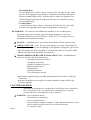
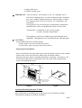
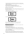
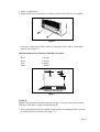
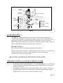
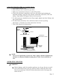
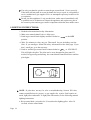
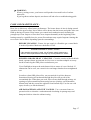
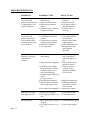
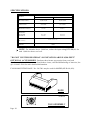
Kozy-World VENT-FREE
GAS-FIRED ROOM HEATER
USER'S OPERATION AND INSTALLATION MANUAL
MODELS:KLH601,602-30,000BTU/HR THERMOSTAT
DESIGN
C ER
T I FIED
WARNING:If the information in this manual is not followed exactly, a fire or
explosion may result causing property damage, personal injury, or loss of life.
- Do not store or use gasoline or other flammable vapors and liquids in the
vicinity of this or any other appliance.
- WHAT TO DO IF YOU SMELL GAS
● Do not try to light any appliance.
● Do not touch any electrical switch; do not use any phone in your building.
● Immediately call your gas supplier from a neighbor's phone. Follow the gas
supplier's instructions.
● If you cannot reach your gas supplier, call the fire department.
- Installation and service must be performed by a qualified installer, service agency
or the gas supplier.
- INSTALLER : LEAVE THIS MANUAL WITH THE CONSUMER
- CONSUMER : RETAIN THIS MANUAL FOR FUTURE REFERENCE
WORLD MARKETING OF AMERICA, INC.
PO Box 192, Route 22 West, Mill Creek, PA 17060-0192
www.worldmkting.com
¿
ƒn
CONTENTS
SECTION I-
General Safety Instructions
3
SECTION II-
Product Identification
4
SECTION III-
Local Codes/National Fuel Code
4
SECTION IV-
Unpacking the Heater Package
5
SECTION V-
Product Features
5
SECTION VI-
Fresh Air for Combustion and Ventilation
5
Installation
6
SECTION VII-
Gas Requirements
10
SECTION VIII-
Leak Checking / Log Placement / Test Fire
12
SECTION IX-
Operating the Heater
13
SECTION X-
Inspecting Burner & Pilot Burner Flames
16
SECTION XI-
Care And Maintenance
17
SECTION XII-
Troubleshooting
18
SECTION XIII
Specifications
20
SECTION XIV-
Accessories
20
SECTION XV-
Parts List
21
SECTION XVI-
Warranty Information
Page 2
GENERAL SAFETY INSTRUCTIONS:
SAFETY : Accidents are always tragic especially because so many of them could
have been prevented with a little care and judgment. There are some basic good
practices we hope you will follow for safe use of your gas-fired room heater.
IMPORTANT : Read this user's manual carefully and completely before
trying to assemble, operate, or service this heater. Improper use of this heater
can cause serious injury or death from burns, fire, explosion, electrical shock,
and carbon monoxide poisoning.
Early signs of carbon monoxide poisoning resemble the flu, with headaches,
dizziness, or nausea. If you have these signs, the heater may not be working
properly. Get fresh air at once! Have heater serviced. Some people are more
affected by carbon monoxide than others. These include pregnant women, people
with heart or lung disease or anemia, those under the influence of alcohol, and those
at high altitudes.
Begin by insuring proper installation and servicing. Follow the installation
instructions provided with this product. Have your heater installed by a qualified
technician. Have the installer show you where the gas supply shut off valve is
located so that you know where to shut off the gas to the heater. If you smell gas,
your installer has not done a proper job of checking leaks. If the connections are not
perfectly seated or tightened, you may have a leak and therefore a faint gas smell.
Finding a leak is not a DO-IT-YOURSELF procedure. Some leaks can only be
found with the main burner gas on and this must be done by a qualified technician.
PRECAUTIONS:
✑ Never use natural gas in a unit designed for liquefied petroleum gases.
✑ Never use liquefied petroleum gases in a unit designed for natural gas.
✑ Check all joints and connections. To avoid the danger of fire, accident or
explosion, never check a potential gas leak with an open flame.
✑ This heater shall not be installed in a bedroom or bathroom.
✑ Never install the heater in any of the following locations:
Recreational vehicle
Where curtains, furniture, clothing, or other flammable objects are less than
36 inches from the front, top, or sides of the heater
Fireplace
High traffic area
Drafty areas
✑ This heater needs fresh, outside air for ventilation to run properly. This heater
has an oxygen depletion sensor(ODS)pilot light safety system. The ODS shuts
down the heater if not enough fresh air/oxygen content(18%)is available.
✑ Never run heater in confined space. Open a door to an adjoining room to help
ventilate(For air openings, see National Fuel Code).
Page 3
✑ If heater shuts off, do not relight until you provide fresh, outside air. If heater
keeps shutting off, have it serviced.
✑ Do not run heater where :
Flammable liquids or vapors are used or stored.
Dusty condition exists.
✑ Never place any objects on the heater.
✑ Supervise children when they are in the same room with heater, never
allow them to sit, stand or play on or around the heater.
✑ Make sure grille guard is in place before running heater.
✑ Do not use heater if any part has been under water. Immediately call a qualified
service technician to inspect the room heater and to replace any part of the
control system and any gas control which has been under water.
✑ Keep appliance area clear and free from combustible materials, gasoline and
other flammable vapors and liquids.
✑ Turn off heater and let cool before servicing. Only a qualified technician should
service and repair heater.
PRODUCT IDENTIFICATION:
Combination Gas Control
Unit Casing Assembly
Screen Guard
Log
Lower Panel
LOCAL CODES
Install and use heater with care. Follow all local codes. In the absence of
local codes, use the latest edition of the National Fuel Gas Code
ANSI Z223 1, also known as NFPA54*
*
Available from:
American National Standards Institute, Inc.
1430 Broadway
New York, NY 10018
National Fire Protection Association, Inc.
Batterymarch Park
Quincy, MA 02269
Page 4
UNPACKING:
1. Remove heater from carton.
2. Remove all protective packaging applied to heater for shipment.
3. Check heater for any shipping damage. If heater is damaged,
promptly inform dealer/distributor where you bought heater.
PRODUCT FEATURES:
Safety Device
This heater has a pilot with an Oxygen Depletion Sensor Shutoff System
(ODS).
The ODS pilot is a required feature for vent-free room heaters. The
ODS pilot shuts off the heater if the normal air oxygen content is reduced
to 18%.
Piezo Ignition System
This heater has a piezo ignitor. This system requires no matches,
batteries, or other sources to light heater.
Thermostatic Heat Control
Thermostat has a sensing bulb, and a control valve. This results in the
greatest heater comfort. This can also result in lower gas bills.
FRESH AIR FOR COMBUSTION AND VENTILATION:
WARNING : This heater must have fresh air for proper operation. If not, poor
fuel combustion could result. Read the following instructions to insure proper fresh
air for this and other fuel-burning appliances in your home.
ADEQUATE COMBUSTION/VENTILATION AIR
All spaces in homes fall into one of the three following ventilation classifications:
Unusually Tight Construction : The air that leaks around doors and windows
may provide enough fresh air for combustion and ventilation. However, in
buildings of unusually tight construction, you must provide additional fresh air.
Unusually Tight Construction is defined as construction where:
-Walls and ceilings exposed to the outside atmosphere have a continuous
water vapor retarder with a rating or one perm or less with openings gasketed or
sealed and
-Weather stripping has been added on openable windows and doors
-Caulking or sealants are applied to areas such as joints around window and
door frames, between sole plates and floors, between wall-ceiling joints,
between wall panels, at penetrations for plumbing, electrical and gas lines, and
at other openings.
Page 5
Unconfined Space
An unconfined space whose volume is not less than 50 cubic feet per 1,000
BTU/HR of the aggregate input rating of all appliances installed in that space.
Rooms communicating directly with the space in which the appliances are
installed, though openings not furnished with doors are considered a part of
the unconfined space.
Confined Space
A confined space whose volume is less than 50 cubic feet for each 1,000
BTU/HR of the aggregate input rating of all appliances in that space.
WARNING : You must provide additional ventilation air in a confined space.
For proper operation of the unit, provide fresh air opening(s) to the room.
Follow the National Fuel Code NFPA 54 / ANSI Z223.1, for required size of
combustion and ventilation openings.
NOTICE : A qualified service person must install heater. Follow all local codes.
CHECK GAS TYPE : Verify the type of gas supply to be used, either natural or
LP(Propane), and make sure the marking on the appliance rating plate agrees with
that of the supply gas. The rating plate is located on the side of the heater, which
indicates the type of gas that heater is orificed for.
ITEMS NEEDED FOR HEATER INSTALLATION: Before installing heater,
make sure you have the items listed below:
Gas piping (check local codes.).
Test gauge connection
Sealant (resistant to LP gases)
Manual shutoff valve*
Sediment trap
Ground joint union
Tee joint and pipe wrench
An installer supplied, design-certified manual shutoff valve with 1/8" NPT tap
connection.
LP gases installation, also requires an installer supplied, design certified gas
pressure regulator.
LOCATING HEATER:
This heater is designed to be mounted on a wall. Heater can be located on
floor, away from a wall. An optional floor mounting base is needed,
purchase the floor mounting base from your dealer.
WARNING : Never install the heater
in a bedroom or a bathroom
in a recreational vehicle
where curtains, furniture, clothing, or other flammable objects are less
than 36 inches from the front, top, or sides of the heater
as a fireplace insert
Page 6
in high traffic areas
in windy or drafty areas
IMPORTANT : Vent-free heaters add moisture to the air. Although this is
beneficial, installing heater in rooms without enough ventilation
may cause mildew formation from too much moisture content.
See National Fuel Code for Fresh Air for Combustion and
Ventilation.
This appliance may be installed in an aftermarket* manufacture
(Mobile) home, where not prohibited by state or local codes.
*Aftermarket : Completion of sale, not for purpose
of resale, from the manufacturer.
This appliance is only for use with the type of gas indicated on the
rating plate. This appliance is not convertible for use with other gases.
CAUTION :
If you install the heater in a home garage:
Heater must be at least 18 inches above floor.
Locate heater where moving vehicle will not hit it.
Preparing For Installation
Select a location for the heater that will provide maximum exposure of the radiant
surface to the room, but will not be subjected to accidental contact.
Adequate clearance must be available around the air opening. See Figures 1 & 2
for clearances that must be maintained to the side walls, floor and horizontal
surface surrounding the heater.
CEILING
13"
Minimum
from
sides of
heater
36"
Minimum
Left
side
Right
side
FL
OO
R
Minimum to top surface
7" of carpeting. Tile or other
combustible material
Figure 1
Figure 2
Attaching Mounting Brackets To Wall
Note: Wall anchors, mounting screws, and spacers are in hardware package.
The hardware package is provided with heater
Page 7
1. Install mounting brackets on wall as shown in Figure 2. Use enclosed “paper
template” for proper location of holes. It may be necessary to use plastic or lead
anchors for plaster walls.
2. Drill holes at marked locations using 9/64"drill bit.
3. Insert mounting screws through bracket and into wall studs.
4. Tighten screws until mounting bracket is firmly fastened to wall studs.
Attaching to wall anchor method
For attaching mounting bracket to hollow walls(wall areas between studs) or solid
walls (concrete or masonry):
1. Drill holes at marked locations using 5/16" drill bit. For solid walls (concrete or
masonry), drill at least 1 inch deep.
2. Insert the plastic anchor as shown in Figure 3 below:
Figure 3
3. Tap anchor flush to wall as shown in Fig.4
Figure 4
4. Insert mounting screws through each bracket and into wall anchors.
5. Tighten screws until mounting bracket is firmly fastened to wall.
Installing Bottom Mounting Screws
1. Locate two bottom mounting holes. These holes are near bottom on back
panel of heater (See Figure 5.).
2. Mark screw locations on wall.
3. Remove heater from mounting bracket.
4. If installing bottom mounting screws into hollow or solid wall, install wall
anchors. Follow steps 1 through 4 under, "Attaching To Wall Anchor Method",
page 8. If installing bottom mounting screw into wall stud, drill holes at marked
locations using 9/64 drill bit.
5. Replace heater onto mounting bracket.
6. Place spacers between bottom mounting holes and wall anchor or drilled hole.
7. Hold spacer in place with one hand. With other hand, insert mounting screw
through bottom mounting hole and spacer. Place tip of screw in opening of wall
Page 8
anchor or drilled hole.
8. Tighten both screws until heater is firmly secured to wall. Do not over tighten.
Figure 5
1. Clearance requirements from surface of carpeting, tile or other combustible
material (See Figure 1.).
Wall Mounted & Floor Mounted With Base Provided
Rear
Sides
Top
Floor
0 Inches
13 Inches
36 Inches
7 Inches
18"
Min.
16"
Adjoining Wall
1.18"
24"
Min.
Floor
30,000 BTU/Hr Model
Figure 6
NOTICE:
Maintain the minimum clearances shown in Figure 1, but you can provide greater
clearances from floor, ceiling and adjoining wall.
2. After mounting brackets are installed, hang heater on mounting brackets in holes
provided at the rear of heater (See Figure 7.).
Page 9
Horizontal
Slots
Mounting
Bracket
(attached to wall)
Stand - Out Tab
Figure 7
3. Installation and repair should be done by a qualified service person. The room
heater should be inspected before use and at least annually by a professional
service person. More frequent cleaning may be required due to excessive lint from
carpeting and other materials. It is imperative that the control compartments,
burners and circulating air passageways of the heater be kept clean.
CONNECTING TO GAS SUPPLY :
WARNING : Never connect an unregulated gas line to the heater.
An installer supplied, design certified gas pressure regulator must be installed to
bring the gas supply pressure down to 14 inches of water column.
IMPORTANT : Check gas line pressure before connecting heater to gas line.
Gas line pressure must not be higher than 14 inches of water. If gas line pressure is
higher, heater gas pressure regulator damage could occur.
CAUTION : Use only new, black iron or steel pipe and internally-tinned copper
tubing may be used in certain areas. Check your local codes. Use pipe of large
enough diameter to allow proper gas volume to heater. If pipe is too small, undue
pressure loss will occur.
Typical Gas Supply Pipe Diameters
30,000 BTU/HR Model 3/8" or greater
CAUTION:
Use pipe joint sealant that is resistant to liquefied petroleum gases.
Install sediment trap in supply line as shown in Figure 8 Gas Connection. Locate
sediment trap where it is within reach for cleaning. Locate sediment trap where
trapped matter is not likely to freeze. A sediment trap traps moisture and
contaminants. This keeps them from going into heater controls. If sediment trap
is not installed or is installed wrong, heater may not run properly.
Page 10
Pressure
Regulator
3/8" NPT
Pipe Nipple
Heater Cabinet
Tee Joint
Test
Gauge
Connection
Ground Joint Union
Reducer
Bushing to
1/8" NPT
Manual
Shutoff
Valve
1/8" NPT
Plug Tab
From
Gas Meter
Tee Joint
Sediment
Trap
Natural Gas
(4" W.C. to
10.5" W.C. Pressure)
L.P Gases
(11.0" W.C. to
14.0" W.C. Pressure)
Pipe
Nipple
Cap
Figure 8
LEAK CHECKING:
GENERAL : Although all gas connections on the heater are leak tested at the
factory prior to shipment, a complete gas tightness check must be performed at the
installation site due to possible mishandling in shipment, or excessive pressure
unknowingly being applied to the appliance. Periodically check the whole system for
leaks, or immediately check if the smell of gas is detected.
BEFORE TESTING
Do not smoke while leak testing. Extinguish all open flames.
Make a soap solution of one part liquid detergent and one part water. You will need
a spray bottle, brush or a piece of rag to apply the solution to the fittings.
For LP units, check with a full cylinder.
CAUTION : NEVER LEAK TEST WITH AN OPEN FLAME
PRESSURE TESTING-GAS SUPPLY PIPING SYSTEM
The appliance and its individual shutoff valve must be disconnected from the gas
supply piping system during any pressure testing of that system at test pressures
in excess of 1/2 psig.
The appliance must be isolated from the gas supply piping system by closing its
individual manual shutoff valve during any pressure testing of the gas supply
piping system at test pressures equal to less than 1/2 psig.
Page 11
LOG PLACEMENT:
This heater is equipped with a decorative ceramic fiber log. This log is designed to utilize two
mounting brackets to ensure proper alignment for consistent good performance without flame
impingement on the log. Follow the following steps for proper log placement:
1. Remove lower panel, screen guard and the packaged ceramic log as shown below.
2. Remove all protective packaging applied to log for shipment.
3. Position and secure the gas log by utilizing both mounting brackets.
4. Install screen guard and lower panel.
Page 12
LEAK TESTING HEATER GAS CONNECTIONS:
1. Open manual shutoff valve.
2. Open main gas valve located near gas meter.
3. Make sure control knob of heater is in the OFF position.
4. Check all joints from manual gas valve up to gas control and including the
manifold assembly. Apply the soap solution around the connections, valve and
tubing. Soap bubbles will appear where a leak is present.
5. If a leak is present, immediately turn off gas supply, tighten any leaky fittings, turn
gas on and recheck.
6. To check burner and safety valve, the burner must be lit (See operating
Instructions.). Check the rest of the connections for leaks.
7. Turn off the heater (See Instructions.).
Open
Manual
Shutoff
Valve
Closed
Manual Shutoff Valve
Combination
Gas Control Location
Manual
Shutoff
Valve
Checking Gas Joints
NOTE:
Never use an open flame to check for a leak. Apply a mixture of liquid soap
and water to all joints. Bubbles forming show a leak. Correct all leaks at
once.
OPERATING HEATER:
WARNING:
Before lighting, smell all around the appliance area for gas. Be sure to smell
next to the floor because some gas is heavier than air and will settle on the
floor. If you smell gas, follow the Safety Instructions on the front page and
under Section I.
Page 13
Use only your hand to push in or turn the gas control knob. Never use tools.
If the knob will not push in or turn by hand, don’t try to repair it, call qualified
service technician or gas supplier. Force or attempted repair may result in a fire
or explosion.
Do not use this appliance if any part has been under water. Immediately call
a qualified service technician to inspect the appliance and replace any part of
the control system and any gas control component which has been under water.
LIGHTING INSTRUCTIONS:
1. Read the aforementioned safety information.
2. Make sure manual shutoff valve is fully open.
3. Push in gas control knob slightly and turn clockwise
to the OFF
position.
4. Wait five minutes to clear any gas. Then smell for gas, including near the
floor. If you smell gas, follow the safety information on the front page. If you
don’t smell gas, go to the next step.
5. Push in and turn gas control knob counterclockwise
to IGN PILOT.
This will light the pilot. The pilot can be seen through the glass panel. If
needed, keep pressing and turning the control knob counterclockwise until the
pilot lights.
PILOT
5
OFF
1
2
4
N
7
NO
IG
6
3
NOTE : If pilot does not stay lit, refer to troubleshooting Section XII. Also,
contact a qualified service person, or gas supplier for repairs. Until repairs are
made, light pilot with match. To light pilot with match, see the following manual
lighting instructions.
6. Keep control knob pressed in for 30 seconds after lighting pilot. After 30
seconds, release control knob.
Page 14
Ignitor Electrode
Thermocouple
Pilot Burner
7. If pilot goes out, repeat steps 3 through 6. This heater has a safety interlock
system. Wait one(1) minute before relighting pilot.
8. When the pilot is lit, turn gas control knob to ON. Turn thermostat control
knob counterclockwise
to desired heating level. The main burner
should light. Set control knob to heat level between 7 and 1.
PILOT
5
OFF
1
2
4
N
7
NO
IG
6
3
CAUTION : Do not try to adjust heating levels by using the manual shutoff valve.
TURNING OFF GAS TO HEATER
Shutting Off Heater
Turn control knob clockwise
to the OFF position.
Shutting Off Burner Only (Pilot stays lit)
Turn control knob clockwise
to the PILOT position.
THERMOSTAT CONTROL OPERATION
The thermostat used on these models differs from standard thermostats. Standard
thermostats simply turn the burner on and off. The thermostat used on this heater
senses the room temperature. The thermostat adjusts the amount of gas flow to the
burner. This increases or decreases the burner flame height/input rating. At times the
room may exceed the set temperature.
If so, the burner will shut off. The burner will cycle back on when room temperature
drops below the set temperature.
Page 15
Note : The thermostat sensing bulb measures the temperature of air near the
heater cabinet. This may not always agree with room temperature (depending
on housing construction, installation location, room size etc.). Frequent use of
your heater will let you determine your own comfort levels.
MANUAL LIGHTING INSTRUCTIONS
1. Remove lower front panel.
2. Follow steps 1 through 4 as stated under Lighting Instructions.
3. Press and turn control knob counterclockwise
to the PILOT position.
4. With control knob pressed in, strike match, hold match to pilot until pilot lights.
5. Keep control knob pressed in for 30 seconds after lighting pilot. After 30
seconds, release control knob.
6. Replace lower front panel.
INSPECTING MAIN BURNER AND PILOT BURNER
Pilot Flame Pattern
The following figures show a correct and incorrect flame patterns. The incorrect
flame is not touching the thermocouple. This will cause a nuisance shut down.
Thermocouple
CORRECT
Pilot Burner
Thermocouple
Pilot Burner
INCORRECT
If pilot flame pattern is incorrect as shown above, turn heater off and refer to
troubleshooting guide.
Burner Flame Pattern
This heater allows the view of flames and provides the simulation of a solid fuel
fireplace. The incorrect log position can cause flame impingement, which can
cause soot formation. Propane installations seem to have more of a sooting
problem due to the richness of LP gas.
Page 16
WARNING :
If heavy sooting occurs, your heater could produce increased levels of carbon
monoxide.
If gas log shows carbon deposit, turn heater off and refer to troubleshooting guide.
CARE AND MAINTENANCE :
Dust, list or debris may affect heater performance. The heater draws air into it during normal
operation. In the process dust, lint or debris will be drawn into the heater and spider webs can
build up during off season. Keep burner, gas control and combustion and circulating air
passageways clean. Inspect or have these areas inspected annually at the beginning of the
heating season by a qualified service person. Room heater may require frequent cleaning due
to excessive lint or debris depending upon the surroundings.
BEFORE CLEANING - Ensure the gas supply is off and the gas control knob
is in the off position. Make sure the heater is cool.
WARNING:DANGER OF BODILY INJURY
If fan assembly accessory is used, turn off power supply at disconnect
switch or service panel before removing any access panels from heater.
BURNER AND ODS PILOT CLEANING - Clean the exterior with soft bristle
brush, vacuum cleaner pressurized air. Never use a wooden toothpick as it may
break off and clog the ODS pilot or main burner port.
Use a flashlight to inspect the main burner inlet to ensure it is not blocked. If
obstruction can be seen, use a metal wire coat hanger that has been straightened
out.
In order to clean ODS pilot orifice, use pressurized air to blow dust out.
Sometimes blowing air backwards through the pilot will get rid of the
accumulated dirt. If that does not work, blow out any dust through primary air
openings of pilot assemblies(Daemyeong has two openings; one beneath the
bimetal strip and the second one opposite from bimetal strip. Use the one wide
open, do not try to lift the bimetal.).
AIR PASSAGEWAYS AND UNIT CASINGS - Use a vacuum cleaner or
pressurized air to clean the combustion and circulating air passageways and
dampened cloth to clean the cabinet/casing.
Page 17
TROUBLESHOOTING:
PROBLEM
Page 18
POSSIBLE CAUSE
WHAT TO DO
When control knob
1. Ignitor electrode posiis pressed in and
tioned wrong.
turned counterclockwise 2. Ignitor electrode broken.
to ignition, there is no
3. Ignitor cable pinched or
spark at ODS pilot.
broken.
4. Ignitor cable not connected
to ignitor electrode.
1. Replace Ignitor
electrode.
2. Replace electrode.
3. Free ignitor cable, if
damaged replace it.
4. Connect cable to
electrode.
When control knob
is pressed in and
turned counterclockwise to ignition/pilot
position, there is spark
but no ignition.
1. Gas supply turned off.
2. Control knob not in pilot
position.
3. Control knob not pressed
in while in pilot position.
4. ODS pilot is clogged.
5. Air in gas Lines.
1. Turn on gas supply.
2. Turn control knob to
pilot position.
3. Press in control while
in pilot position.
4. Call a qualified person
5. Purge gas lines and
repeat ignition
operation.
ODS pilot lights but
flame goes out when
control knob is
released.
1. Control knob not pressed
long enough.
Burner does not light
after ODS pilot is lit
1. Burner orifice clogged.
2. Gas supply pressure is very
low.
Delayed ignition
1. Main burner carry over ports 1. Clean main burner ports.
clogged.
2. Gas supply pressure is very 2. Call your gas supplier.
low.
1. After ODS pilot lights,
keep control knob
pressed in approx. 30
sec.
2. Safety interlock is triggered. 2. Wait a minute, repeat
ignition operation.
3. Pilot flame not touching
3. Contact your gas
the thermocouple. Problem
company or gas
could be result of one or
supplier or qualified
both of the following:
service person.
Partially clogged ODS pilot
orifice.
Low gas pressure.
4. Thermocouple damaged.
4. Replace thermocouple.
5. Thermocouple connection
5. Hand tight until snug
loose at gas control valve.
then tighten 1/4 turn
with a wrench.
6. Gas control valve damaged. 6. Replace gas control.
1. Clean burner orifice.
2. Contact the Gas Co.
PROBLEM
POSSIBLE CAUSE
WHAT TO DO
Burner backfiring
during operation
1. Burner orifice is clogged.
2. Burner ports damaged.
1. Clean burner orifice.
2. Replace burner.
Extremely sooty flame.
1. Lack of primary air.
Slight smoke and odor
during initial operation
1. Residues from
manufacturing processes.
1. Will stop after a few
hours of operation.
Heater produces a
whistling noise when
burner is lit.
1. Air passageways blocked.
1. Check minimum
installation clearances
and air passageways for
debris.
2. Operate burner until the
air is completely purged.
1. Check primary air
opening for blockage.
2. Flame impingement on log. 2. Check & correct log
position.
3. Install correct orifice
3. Incorrect orifice size.
size for right type of gas
& elevation.
2. Air in gas line
Heater produces a
clicking noise just
after burner is lit or
turned off.
1. Metal expanding and
contracting, respectively.
1. This is common with
heaters. If noise is
excessive, contact a
qualified person.
Gas odor even when
control knob is in OFF
position.
1. Gas leaks. See front page
Warnings.
2. Gas control defective
1. Locate and correct leaks
immediately.
2. Replace gas control
Gas odor during
combustion
1. Foreign matter in gas or on 1. Check gas passage way
and burner.
burner ports.
2. Heater burning vapors from 2. Ventilate room, stop
storing and using odor
paint, impurities in air.
causing products near
the heater.
3. Locate and correct
3. Gas leaks. See front page
leaks immediately.
Warnings.
Heater shuts off
on ODS
1. Not enough fresh air is
available.
2. Low gas pressure
1. Open window.
2. Contact your gas
company.
3. ODS pilot partially clogged. 3. Clean the pilot.
Page 19
SPECIFICATIONS:
KLH(601,602)
MODELS
INPUT RATING
(BTU/HR,Variable)
TYPE OF GAS
REGULATOR
PRESSURE SETTING
INLET GAS SUPPLY
PRESSURE:
MAXIMUM
MINIMUM
601
602
30,000/15,000
30,000/15,000
NATURAL
LP GASES
3.0″W.C.
8.0″W.C.
10.5″W.C.
4.0″W.C.
14.0″W.C.
11.0″W.C.
SIZE OF HEATER
(H×W×D)
WEIGHT
23.8″×25.7″×8″
30LBS
NOTE : For altitudes above 2,000 feet, reduce the input rating(BTU/HR)4% for
each 1,000 feet above sea level.
"DO NOT USE THIS HEATER AT AN ELEVATION ABOVE 4,500 FEET"
OPTIONAL ACCESSORIES : Purchase these heater accessories from your local
distributors/dealers. If they can not furnish these items, call World Marketing of America, Inc.
@1-814-643-2299 for more detailed information.
FLOOR MOUNTING BASE : No. 20-5241 may be used for MODEL(KLH 601,602).
BASE
20-6024
FAN ASSEMBLY
Page 20
PARTS LIST
Page 21
PARTS LIST
ITEM
NO.
DESCRIPTION
1.
2.
3.
4.
5.
6.
7.
8.
9.
10.
11.
12.
13.
14.
15.
16.
17.
18.
19.
19-1.
19-2.
20.
21.
22.
23.
24.
25.
26.
27.
Unit Casing Assembly
Main Burner Assembly
Firebox Assembly
Log
Screen Guard
Cover Heat
Lower Panel
Burner Support-L/R
Valve Bracket
Combination Gas Control
Pressure Regulator(3/8") [NG:3", LP:8"]
Mounting Bracket-Log
Inlet Tubing Assembly
Outlet Tubing Assembly
Nozzle Holder
Nozzle Holder Nut
Main Nozzle
O.D.S Pilot Tubing(3/16") Assembly
O.D.S Pilot Assembly (Daemyeong Korea )
Electrode
Thermocouple
Connector-A
Connector-B
Connector-C
Wall Mounting Bracket-L/R
Wall Mounting Screw
Regulator Fix Screw
O.D.S Mounting Screw
Screw
Page 22
PART NO. FOR
KLH(601,602)
REF-2A0052
20-0131
20-0149(1A0076)
20-3046(1A0078)
20-5450(1A0077)
REF-1A0026
REF-1A1013
REF-2A0094L/R
REF-3A0048
20-1037/20-1038(GV30 30N3/L8)
20-9957/20-9958(DR40T3KN/L)
REF
REF
REF
REF-4A1027
REF-4A1028
20-4023/20-4022
REF-2A1034
20-3097/20-3098(DS98JN/L02)
REF-4A0020
REF-4A0021
REF-4A0022
20-9801(3A1010)
20-9607#32
20-9604#31
20-9605#30
20-9606#29
LIMITED WARRANTY:
This limited warranty is extended to the original retail purchaser of this Kozy-World Heater and
warrants against any defect in materials in workmanship for a period of one (1) year from the date
of retail sale. World Marketing of America, Inc., at it's option, will either provide replacement parts
or replace or repair the unit, when properly returned to the retailer, within one (1) year of retail
purchase. (Shipping costs, installation or removal of the unit and any other associated field labor
costs are the responsibility of the purchaser.)
DUTIES OF THE OWNER:
This heating appliance must be installed and tested by a qualified individual and operated in
accordance with the written instructions fumished with this heater. This warranty shall not
excuse the owner from properly maintaining this heater in accordance with the written
instructions furnished with this heater. A bill of sale, canceled check or payment record must be
kept to verify purchase date and establish warranty period. Original carton should be kept in case
of warranty return of unit.
WHAT IS NOT COVERED:
Travel, diagnostic cost, service labor, labor to repair the defective appliance and freight charges on
warranty parts or heaters to and from the factory shall be the responsibility of the owner.
This warranty does not imply or assume any responsibility for consequential damages that may
result from the use, misuse, improper installation or the lack of routine maintenance of this
heating appliance. A cleaning fee and the cost of parts may be charged for appliance failures
resulting from the lack of maintenance. This warranty does not cover claims which do not
involve defective workmanship or matenals. FAILURE TO PERFORM GENERAL MAINTENANCE
(INCLUDING CLEANING) WILL VOID THIS WARRANTY.
THIS LIMITED WARRANTY IS GIVEN TO THE PURCHASER IN LIEU OF ALL OTHER
WARRANTIES, EXPRESSED OR IMPLIED, INCLUDING BUT NOT LIMITED TO THE
WARRANTIES OF MERCHANT ABILITY OF FITNESS FOR A PARTICULAR PURPOSE. THE
REMEDY PROVIDED IN THIS WARRANTY IS EXCLUSIVE AND IS GRANTED IN LIEU OF ALL
OTHER REMEDIES. IN NO EVENT WILL WORLD MARKETING OF AMERICA BE LIABLE
FOR INCIDENTAL OR CONSEQUENTIAL DAMAGES.
Some states do not allow limitations on how long an implied warranty lasts, so the above
limitation may not apply to you. Some states do not allow the exclusion or limitation of
incidental or consequential damages so the above limitation or exclusion may not apply to you.
CLAIMS HANDLED AS FOLLOWS:
1. Contact your retailer and explain your problem.
2. If the retailer cannot resolve the problem, write out. Consumer Warranty Dept. detailing the
heater model, the problem, copy of the sales receipt or date of purchase. Send letter to the
attention of "Warranty Claims Administrator."
3. A representative of Kozy-World will contact you. DO NOT RETURN THE HEATER TO
WORLD MARKETING OF AMERICA, INC.
This warranty gives you specific legal rights and you may also have other rights which vary from
state to state.
DO NOT RETURN THE HEATER TO WORLD MARKETING OF AMERICA, INC. YOU WILL
BE CONTACTED BY OUR REPRESENTATIVE.
TO REGISTER THE WARRANTY ON YOUR HEATER, PLEASE FILL OUT THIS CARD
COMPLETELY AND MAIL WITHIN 14 DAYS FROM DATE OF PURCHASE.
NAME:
ADDRESS:
CITY:
MODEL:
SERIAL #.
DEALER PURCHASED FORM:
CITY & STATE WHERE PURCHASED:
PHONE:(
)
STATE:
ZIP:
DATE PURCHASED:
TYPE OF STORE:
PRICE PAID:
Please Take a Minute To Give Us Your Answers To The Following Questions.
All Responses Are Used Solely For Market Research And Are Held In Strict Confidence.
Do you own any other portable heaters?
Yes
No
If you do: How many?
What Brands?
Satisfied?
Please indicate your age group: Under 25, 32-34, 35-44, 45-54, 55-64, 65 or older
How do you intend to use your new heater? Emergency Heat, Extra Heat, Primary Heat
Were did you hear about this heater?
What made you select this heater? Price, Store Display, Salesperson, Recommendation,
Radio ad, Newspaper ad, Other (Please Specify)
What is your occupation?
What is your income bracket?
A. Under $15,000 B. $15-30,000 C. $30-45,000
D. $45-60,000
E. Over $60,000
Do you own or rent your home?
Would you recommend this heater to a friend?
THANK YOU FOR COMPLETING THIS FORM!
SOLVING COMMON PROBLEMS
The 3 most common problems associated with any gas heater are gas leaks, wrong gas
pressure and dirt.
Do Not Use Your Heater Without Checking For Leaks! Leaks can occur during shipment and
installation. A simple solution of soap and water dabbed on the fittings will bubble if a gas leak is
present. Do not take short cuts!
Wrong Gas Pressure! Too much gas pressure may severely damage your heater. Too little gas
pressure and your heater will not burn correctly. If your installer can not check gas pressure, find
one who can or call your gas supplier. Do not take shortcuts!
Dust & Dirt! This heater does require some cleaning. If the pilot light will not stay lit or if one brick is
not as bright as another, your heater is probably due for a good cleaning.
Replacement of the thermocouple or pilot assembly is generally not needed. Review Heater
Maintenance on page 15 of the owners manual.
While we want every one to be completely satisfied with their purchase it is impossible to cover
problems occurring form improper installation or a lack of maintenance.
Kozy-World Warranty Registration
IMPORTANT: We urge you to fill out your warranty registration card within ten(10) days of date of
installation, complete with the entire serial number which can be found on the rating plate. Retain
this portion of the card for your records.
World Marketing of America, Inc.
PO Box 192, Route 22 West
Mill Creek, PA 17060-0192
Tel) 1-814-643-2299
SAVE THIS CARD!
Place
Postage
Stamp
Here
World Marketing of America, Inc.
PO Box 192, Route 22 West
Mill Creek, PA 17060-0192


![Quest Elite 2000-Hydro Carbon Service Manual [ 033857 ]](http://vs1.manualzilla.com/store/data/006004650_1-f9b7a3a43e3300051ad30d285820ff91-150x150.png)