1
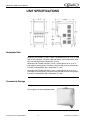
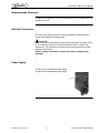
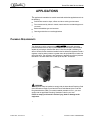
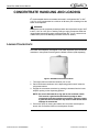
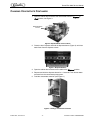
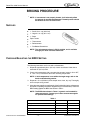
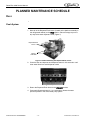
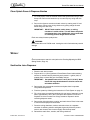
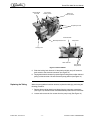
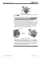
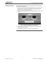
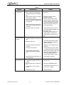
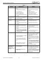
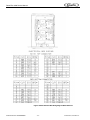
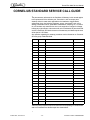
QUEST ELITE 4000 Service Manual Release Date: December 18, 2010 Publication Number: 620048956SER Revision Date: January 6, 2015 Revision: G Visit the Cornelius web site at www.cornelius.com for all your Literature needs. The products, technical information, and instructions contained in this manual are subject to change without notice. These instructions are not intended to cover all details or variations of the equipment, nor to provide for every possible contingency in the installation, operation or maintenance of this equipment. This manual assumes that the person(s) working on the equipment have been trained and are skilled in working with electrical, plumbing, pneumatic, and mechanical equipment. It is assumed that appropriate safety precautions are taken and that all local safety and construction requirements are being met, in addition to the information contained in this manual. This Product is warranted only as provided in Cornelius’ Commercial Warranty applicable to this Product and is subject to all of the restrictions and limitations contained in the Commercial Warranty. Cornelius will not be responsible for any repair, replacement or other service required by or loss or damage resulting from any of the following occurrences, including but not limited to, (1) other than normal and proper use and normal service conditions with respect to the Product, (2) improper voltage, (3) inadequate wiring, (4) abuse, (5) accident, (6) alteration, (7) misuse, (8) neglect, (9) unauthorized repair or the failure to utilize suitably qualified and trained persons to perform service and/or repair of the Product, (10) improper cleaning, (11) failure to follow installation, operating, cleaning or maintenance instructions, (12) use of “non-authorized” parts (i.e., parts that are not 100% compatible with the Product) which use voids the entire warranty, (13) Product parts in contact with water or the product dispensed which are adversely impacted by changes in liquid scale or chemical composition. Contact Information: To inquire about current revisions of this and other documentation or for assistance with any Cornelius product contact: www.cornelius.com 800-238-3600 Trademarks and Copyrights: This document contains proprietary information and it may not be reproduced in any way without permission from Cornelius. This document contains the original instructions for the unit described. CORNELIUS INC 101 Regency Drive Glendale Heights, IL Tel: + 1 800-238-3600 Printed in U.S.A. TABLE OF CONTENTS Safety Instructions. . . . . . . . . . . . . . . . . . . . . . . . . . . . . . . . . . . . . . . . . . . . . . . . . . . . . . . . . . . . . . . . . 1 Read and Follow ALL Safety Instructions . . . . . . . . . . . . . . . . . . . . . . . . . . . . . . . . . . . . . . . . . . . . . 1 Safety Overview . . . . . . . . . . . . . . . . . . . . . . . . . . . . . . . . . . . . . . . . . . . . . . . . . . . . . . . . . . . 1 Recognition . . . . . . . . . . . . . . . . . . . . . . . . . . . . . . . . . . . . . . . . . . . . . . . . . . . . . . . . . . . . . . 1 Different Types of Alerts. . . . . . . . . . . . . . . . . . . . . . . . . . . . . . . . . . . . . . . . . . . . . . . . . . . . . . . . 1 Safety Tips . . . . . . . . . . . . . . . . . . . . . . . . . . . . . . . . . . . . . . . . . . . . . . . . . . . . . . . . . . . . . . . . . . . . . 1 Qualified Service Personnel. . . . . . . . . . . . . . . . . . . . . . . . . . . . . . . . . . . . . . . . . . . . . . . . . . . . . . . . 2 Safety Precautions. . . . . . . . . . . . . . . . . . . . . . . . . . . . . . . . . . . . . . . . . . . . . . . . . . . . . . . . . . . . . . . 2 Shipping And Storage . . . . . . . . . . . . . . . . . . . . . . . . . . . . . . . . . . . . . . . . . . . . . . . . . . . . . . . . . . . . 2 Mounting in or on a Counter . . . . . . . . . . . . . . . . . . . . . . . . . . . . . . . . . . . . . . . . . . . . . . . . . . . . . . . 3 Unit Specifications. . . . . . . . . . . . . . . . . . . . . . . . . . . . . . . . . . . . . . . . . . . . . . . . . . . . . . . . . . . . . . . . . 4 Nameplate Data . . . . . . . . . . . . . . . . . . . . . . . . . . . . . . . . . . . . . . . . . . . . . . . . . . . . . . . . . . . . . . 4 Concentrate Storage . . . . . . . . . . . . . . . . . . . . . . . . . . . . . . . . . . . . . . . . . . . . . . . . . . . . . . . . . . 4 Recommended Clearance . . . . . . . . . . . . . . . . . . . . . . . . . . . . . . . . . . . . . . . . . . . . . . . . . . . . . . 5 Electrical Connection . . . . . . . . . . . . . . . . . . . . . . . . . . . . . . . . . . . . . . . . . . . . . . . . . . . . . . . . . . 5 Power Supply . . . . . . . . . . . . . . . . . . . . . . . . . . . . . . . . . . . . . . . . . . . . . . . . . . . . . . . . . . . . . . . . 5 Water Connection . . . . . . . . . . . . . . . . . . . . . . . . . . . . . . . . . . . . . . . . . . . . . . . . . . . . . . . . . . . . 6 Water Supply Requirements . . . . . . . . . . . . . . . . . . . . . . . . . . . . . . . . . . . . . . . . . . . . . . . . . . . . 6 Ice Bank/Pull Down . . . . . . . . . . . . . . . . . . . . . . . . . . . . . . . . . . . . . . . . . . . . . . . . . . . . . . . . . . . 6 Applications . . . . . . . . . . . . . . . . . . . . . . . . . . . . . . . . . . . . . . . . . . . . . . . . . . . . . . . . . . . . . . . . . . . . . . 7 Plumbing Requirements. . . . . . . . . . . . . . . . . . . . . . . . . . . . . . . . . . . . . . . . . . . . . . . . . . . . . . . . . . . 7 Concentrate Handling and Loading . . . . . . . . . . . . . . . . . . . . . . . . . . . . . . . . . . . . . . . . . . . . . . . . . . . 8 Loading Concentrate . . . . . . . . . . . . . . . . . . . . . . . . . . . . . . . . . . . . . . . . . . . . . . . . . . . . . . . . . . . . . 8 Changing Concentrate Containers. . . . . . . . . . . . . . . . . . . . . . . . . . . . . . . . . . . . . . . . . . . . . . . . . . . 9 BRIXING Procedure . . . . . . . . . . . . . . . . . . . . . . . . . . . . . . . . . . . . . . . . . . . . . . . . . . . . . . . . . . . . . . . 10 Supplies . . . . . . . . . . . . . . . . . . . . . . . . . . . . . . . . . . . . . . . . . . . . . . . . . . . . . . . . . . . . . . . . . . . . . . 10 Checking/Adjusting the BRIX Setting. . . . . . . . . . . . . . . . . . . . . . . . . . . . . . . . . . . . . . . . . . . . . . . . 10 Planned Maintenance Schedule . . . . . . . . . . . . . . . . . . . . . . . . . . . . . . . . . . . . . . . . . . . . . . . . . . . . . 12 Daily . . . . . . . . . . . . . . . . . . . . . . . . . . . . . . . . . . . . . . . . . . . . . . . . . . . . . . . . . . . . . . . . . . . . . . . . . 12 Flush System . . . . . . . . . . . . . . . . . . . . . . . . . . . . . . . . . . . . . . . . . . . . . . . . . . . . . . . . . . . . . . . 12 Clean Splash Zones & Dispense Nozzles . . . . . . . . . . . . . . . . . . . . . . . . . . . . . . . . . . . . . . . . . 13 Weekly . . . . . . . . . . . . . . . . . . . . . . . . . . . . . . . . . . . . . . . . . . . . . . . . . . . . . . . . . . . . . . . . . . . . . . . 13 Sanitize the Juice Dispenser . . . . . . . . . . . . . . . . . . . . . . . . . . . . . . . . . . . . . . . . . . . . . . . . . . . 13 Sanitize Pump System . . . . . . . . . . . . . . . . . . . . . . . . . . . . . . . . . . . . . . . . . . . . . . . . . . . . . . . . 14 Prepare Dispenser for Use. . . . . . . . . . . . . . . . . . . . . . . . . . . . . . . . . . . . . . . . . . . . . . . . . . . . . 14 Semi Annually . . . . . . . . . . . . . . . . . . . . . . . . . . . . . . . . . . . . . . . . . . . . . . . . . . . . . . . . . . . . . . . . . 15 Clean Water Inlet Strainer . . . . . . . . . . . . . . . . . . . . . . . . . . . . . . . . . . . . . . . . . . . . . . . . . . . . . 15 Clean Chassis Interior . . . . . . . . . . . . . . . . . . . . . . . . . . . . . . . . . . . . . . . . . . . . . . . . . . . . . . . . 15 Check and Top-Off Water Ice Bath . . . . . . . . . . . . . . . . . . . . . . . . . . . . . . . . . . . . . . . . . . . . . . 16 Annually . . . . . . . . . . . . . . . . . . . . . . . . . . . . . . . . . . . . . . . . . . . . . . . . . . . . . . . . . . . . . . . . . . . . . . 16 Replace Pump Tubing and Clean Cabinet. . . . . . . . . . . . . . . . . . . . . . . . . . . . . . . . . . . . . . . . . 16 Removing Pump Platform(s) . . . . . . . . . . . . . . . . . . . . . . . . . . . . . . . . . . . . . . . . . . . . . . . . 16 Replacing the Tubing . . . . . . . . . . . . . . . . . . . . . . . . . . . . . . . . . . . . . . . . . . . . . . . . . . . . . . 17 Cleaning the Cabinet . . . . . . . . . . . . . . . . . . . . . . . . . . . . . . . . . . . . . . . . . . . . . . . . . . . . . . 19 Troubleshooting Guide . . . . . . . . . . . . . . . . . . . . . . . . . . . . . . . . . . . . . . . . . . . . . . . . . . . . . . . . . . . . 20 Assembly Drawings. . . . . . . . . . . . . . . . . . . . . . . . . . . . . . . . . . . . . . . . . . . . . . . . . . . . . . . . . . . . . . . 23 Cornelius Standard Service Call Guide . . . . . . . . . . . . . . . . . . . . . . . . . . . . . . . . . . . . . . . . . . . . . . . 25 Quest Elite 4000 Service Manual SAFETY INSTRUCTIONS READ AND FOLLOW ALL SAFETY INSTRUCTIONS Safety Overview • Read and follow ALL SAFETY INSTRUCTIONS in this manual and any warning/caution labels on the unit (decals, labels or laminated cards). • Read and understand ALL applicable OSHA (Occupational Safety and Health Administration) safety regulations before operating this unit. Recognition Recognize Safety Alerts ! This is the safety alert symbol. When you see it in this manual or on the unit, be alert to the potential of personal injury or damage to the unit. Different Types of Alerts ! DANGER: Indicates an immediate hazardous situation which if not avoided WILL result in serious injury, death or equipment damage. ! WARNING: Indicates a potentially hazardous situation which, if not avoided, COULD result in serious injury, death, or equipment damage. ! CAUTION: Indicates a potentially hazardous situation which, if not avoided, MAY result in minor or moderate injury or equipment damage. SAFETY TIPS © 2010-2015, Cornelius Inc. • Carefully read and follow all safety messages in this manual and safety signs on the unit. • Keep safety signs in good condition and replace missing or damaged items. • Learn how to operate the unit and how to use the controls properly. • Do not let anyone operate the unit without proper training. This appliance is not intended for use by very young children or infirm persons without supervision. Young children should be supervised to ensure that they do not play with the appliance. -1- Publication Number: 620048956SER Quest Elite 4000 Service Manual • Keep your unit in proper working condition and do not allow unauthorized modifications to the unit. QUALIFIED SERVICE PERSONNEL ! WARNING: Only trained and certified electrical, plumbing and refrigeration technicians should service this unit. ALL WIRING AND PLUMBING MUST CONFORM TO NATIONAL AND LOCAL CODES. FAILURE TO COMPLY COULD RESULT IN SERIOUS INJURY, DEATH OR EQUIPMENT DAMAGE. SAFETY PRECAUTIONS This unit has been specifically designed to provide protection against personal injury. To ensure continued protection observe the following: ! WARNING: Disconnect power to the unit before servicing following all lock out/tag out procedures established by the user. Verify all of the power is off to the unit before any work is performed. Failure to disconnect the power could result in serious injury, death or equipment damage. ! CAUTION: Always be sure to keep area around the unit clean and free of clutter. Failure to keep this area clean may result in injury or equipment damage. SHIPPING AND STORAGE ! CAUTION: Before shipping, storing, or relocating the unit, the unit must be sanitized and all sanitizing solution must be drained from the system. A freezing ambient environment will cause residual sanitizing solution or water remaining inside the unit to freeze resulting in damage to internal components. Publication Number: 620048956SER -2- © 2010-2014, Cornelius Inc. Quest Elite 4000 Service Manual MOUNTING IN OR ON A COUNTER ! WARNING: When installing the unit in or on a counter top, the counter must be able to support a weight in excess of 189 lbs. (85.7 kg.) to insure adequate support for the unit. FAILURE TO COMPLY COULD RESULT IN SERIOUS INJURY, DEATH OR EQUIPMENT DAMAGE. © 2010-2015, Cornelius Inc. -3- Publication Number: 620048956SER Quest Elite 4000 Service Manual UNIT SPECIFICATIONS Figure 1. Unit Dimensions Nameplate Data Model QST ELITE 4000, 115 VAC, 5 amps, 1 phase 60 hertz, 6.34 – 6.41 oz. (180182) R-134a refrigerant. Test press: High side 400 psi (2757.9 kilopascals), (27.6 bar). Low side 88 psi (606.7 kilopascals), (6.1 bar). Model Quest ELITE 4000, 230 VAC, 2 amps, 1 phase 50 hertz, 6.34 - 6.41 oz. (180-182g) R-134a refrigerant. Test press: High side 400 psi (2757.9 kilopascals) (27.6 bar). Low side 88 psi (606.7 kilopascals), (6.1 bar). Model Quest ELITE 4000, 220 VAC, 2 amps, 1 phase 60 hertz, 6.34 - 6.41 oz. (180-182g) R-134a refrigerant. Test press: High side 400 psi (2757.9 kilopascals) (27.6 bar). Low side 88 psi (606.7 kilopascals), (6.1 bar). Concentrate Storage Four 0.8 gallon (3.0 liter) disposable bottles. Publication Number: 620048956SER -4- © 2010-2014, Cornelius Inc. Quest Elite 4000 Service Manual Recommended Clearance 12” (30.48 cm) on top and 4” (10.16 cm) required in back for air circulation and 4” at the sides of the unit. Electrical Connection 6 ft. long (1.83 m) power cord with 3-prong plug attached to dispenser. Export models are shipped with a European plug. ! CAUTION: ONLY trained and certified electrical technicians should replace the power cord or the unit should be returned to an Authorized Service Center for power cord replacement.” The replacement cord must meet all requirements of the original equipment manufacturer. Failure to comply could result in serious injury, death or damage to the equipment. Power Supply 15 amps at 120 volts dedicated power supply. 10 amps at 230 volts dedicated power supply. © 2010-2015, Cornelius Inc. -5- Publication Number: 620048956SER Quest Elite 4000 Service Manual Water Connection 3/8 in. (0.95 cm) SAE male flare fitting on dispenser. Water Supply Requirements 60 psi (413.7 kilopascals) (4.1 bar) maximum static pressure. 30 psi (206.8 kilopascals) (2.1 bar) minimum dynamic pressure; i.e., flowing pressure measured at dispenser water inlet with 3 OZ (88.7 ml) per second water flow. Optimum recommended pressure 50 psi (344.7 kilopascals) (3.5 bar) dynamic pressure. Ice Bank/Pull Down Weight 14-16 lbs. (6.35-7.25 kg.). Pull Down: 3.5-5.5 hours at 75°F (24°C) Publication Number: 620048956SER -6- © 2010-2014, Cornelius Inc. Quest Elite 4000 Service Manual APPLICATIONS This appliance is intended to be used in household and similar applications such as the following: • Staff kitchen areas in shops, offices and other working environments. • Farm houses and by clients in hotels, motels and other residential type environments • Bed and breakfast type environments • Catering and similar non-retail applications PLUMBING REQUIREMENTS This dispenser must be connected to a COLD WATER system with operating pressure between 20 and 100 psi (138 and 690 kPa). This water source must be capable of producing a minimum flow rate of 3 fluid ounces (88.7 milliliters) per second. A shut off valve should be installed in the line before the dispenser. Install a regulator in the line when pressure is greater than 100 psi (690 kPa) to reduce it to 50 psi (345 kPa). The regulator is also necessary if the water source has pressure flucuations. The main water inlet is a 3/8” (9.52 mm) MFL connection. Water Connection ! WARNING: This equipment must be installed to comply with the International Plumbing Code of the International Code Council and the Food Code Manual of the Food and Drug Administration (FDA). For models installed outside the U.S.A., you must comply with the applicable Plumbing, Sanitation Code for your area. Failure to comply could result in serious injury, death or damage to the equipment. © 2010-2015, Cornelius Inc. -7- Publication Number: 620048956SER Quest Elite 4000 Service Manual CONCENTRATE HANDLING AND LOADING It is recommended that the concentrate be thawed in a refrigerated 35°F to 40°F (1.6°C to 4.4°C) compartment for a minimum of 48 hours prior to loading it into the Quest Juice Dispenser. ! WARNING: Concentrate must be completely thawed and within the temperature range of 35°F to 40°F (1.6°C to 4.4°C) prior to loading. Failing to supply concentrate inside the recommended temperature range, especially below 35°F (1.6°C), causes an out of BRIX drink (refer to the BRIXing Procedure section for details). LOADING CONCENTRATE The Quest Juice Dispenser is designed to use either disposable juice concentrate containers or the optional Cornelius generic refillable container (sold separately). Figure 2. Refillable Concentrate Container 1. Thoroughly shake concentrate container prior to use. 2. Place concentrate containers on the dispensing platform shelf inside the refrigerated cabinet. 3. Engage the concentrate container by pressing it downward into the bottle adapter opening on the dispensing platform. NOTE: Be sure to lubricate the o-ring seal on the container nozzle. This ensures a good seal and allows the pumps to draw concentrate from the containers more easily. Failure to create a good seal at this connection may result in weak drinks and/or seepage of concentrate. 4. Prime each pump by closing the cabinet door and press each dispense button until concentrate flows from the dispense nozzles. Publication Number: 620048956SER -8- © 2010-2014, Cornelius Inc. Quest Elite 4000 Service Manual CHANGING CONCENTRATE CONTAINERS 1. Open the cabinet door and move the valve handle from the Dispense to Flush position, see Figure 3. Dispense/Flush Levers Figure 3. Dispense/Flush Lever Location 2. Close the door. Depress and hold the dispense button (Figure 4) until clear water flows from the dispense nozzle. Figure 4. Dispense Buttons 3. Open the cabinet door and return the handle to the Dispense position. 4. Depress and hold the dispense button for 1-2 seconds. This relieves water pressure from the concentrate pump system. 5. Load the concentrate container (see Figure 5 ) Figure 5. Loading a Concentrate Container © 2010-2015, Cornelius Inc. -9- Publication Number: 620048956SER Quest Elite 4000 Service Manual BRIXING PROCEDURE NOTE: If concentrate is not properly thawed, it will adversely affect the amount of concentrate dispensed. Thawed product should be between 35°F/1.6°C to 40°F/4.4°C. SUPPLIES • 1 - Small 12 oz. cup (354.8 ml) • 1 - Large 21 oz. cup (621.1 ml) • 1 - Straw • Paper Towels • 1 - Thermometer • 1 - Refractometer • 1 - Flat Bladed Screwdriver NOTE: The refractometer shown is P/N 511004000, and is available through your local Cornelius Distributor. CHECKING/ADJUSTING THE BRIX SETTING The following instructions are for use with a refractometer. 1. Dispense approximately 8 oz. (237 ml) of drink and discard. Now draw a second 8 oz. (237 ml) drink. 2. Check drink temperature with a accurate thermometer (target is 35 to 45°F, or 1.6 to 7.2°C). Discard this drink after checking temperature. NOTE: If drink temperature is not within the target range, refer to the basic troubleshooting section. 3. Dispense a 12 oz (354.8 ml) drink sample into a clean, dry cup. Thoroughly stir the sample using a straw. 4. Using the straw, transfer a small sample of the finished drink to the refractometer lens (refer to operating instructions supplied with your refractometer). Check the BRIX reading against the BRIX chart shown in Table 1. NOTE: The BRIX chart shown in Table 1 is generic and intended for reference use only. Contact your frozen concentrate supplier for specific BRX readings. Table 1. Flavor Publication Number: 620048956SER Ratio BRIX Orange Juice 4+1 11.8 Grapefruit Juice 5+1 10.6 Cranberry Cocktail 4+1 13.5 Apple Juice 5+1 12.0 Grape 5+1 13.0 - 10 - © 2010-2014, Cornelius Inc. Quest Elite 4000 Service Manual Table 1. Flavor Ratio BRIX Lemonade 5+1 10.5 Tropical Punch 5+1 11.8 Sweetened Ice Tea 7+1 6.0 Pineapple Juice 4+1 12.8 Prune Juice 2+1 16.0 5. To change the BRIX setting, simply readjust the water flow rate. Located on each of the valve assemblies inside the refrigerated compartment are the adjusting screws for the water flow rate (one per valve). If the BRIX reading is too high or low, rotate the appropriate water flow control according to Figure 6. Repeat steps 1-5 until the proper BRIX setting is achieved. Water Flow Controls Dispense/Flush Lever Figure 6. BRIX Adjustment IMPORTANT: When making changes to the water flow control, do not rotate more than 1/4 turn per adjustment. Additionally, prior to taking your next BRIX reading, momentarily press the corresponding dispense button several times prior to drawing a sample. This clears any remnants from the dispense nozzle AND helps move the flow control to its new setting. © 2010-2015, Cornelius Inc. - 11 - Publication Number: 620048956SER Quest Elite 4000 Service Manual PLANNED MAINTENANCE SCHEDULE DAILY Flush System 1. Move all of the Dispense/Flush levers (located on the platform assembly in the refrigerated cabinet) to the Flush position. Place an empty cup on the drip tray below each dispense nozzle (Figure 7). Dispense/Flush Levers Mixing Chambers Figure 7. Platform Assembly with Dispense/Flush Levers 2. Close the door and depress each dispense button for 2-3 seconds or until clear water flows from each dispense nozzle. Figure 8. Dispense Buttons 3. Return the Dispense/Flush levers to the Dispense position. 4. Press each Dispense button for 1 to 2 seconds to release the water pressure present in the concentrate pump system. Publication Number: 620048956SER - 12 - © 2010-2014, Cornelius Inc. Quest Elite 4000 Service Manual Clean Splash Zones & Dispense Nozzles 1. On a daily basis, clean the external cabinet and splash areas using a clean damp cloth. Remove and wash the cup rest and drip tray using mild dish soap. 2. Remove the dispense nozzles and static mixers by rotating each 90° and pulling down. Remove the mixing chambers by pulling straight forward. Wash using mild dish soap. IMPORTANT: DO NOT wash nozzles, static mixers, or mixing chambers in a dish washer. This will distort the plastic and damage the o-rings. Additionally, do not soak them in sanitizing solution longer than 2 minutes. Flush once a day for better quality drinks. ! WARNING: Do not leave the unit in FLUSH mode. Leaving the unit in flush mode may result in damage. WEEKLY Check concentrate to water brix ratio (refer to the Checking/Adjusting the BRIX Setting Section, Page 10). Sanitize the Juice Dispenser 1. Rinse the unit with hot water. 2. Prepare two 2 oz. (59 ml) packets of Stera-Sheen Green Label sanitizing solution (or similar brand) by dissolving each packet in 1 gallon (3.8L) of potable water to insure 200 ppm of available chlorine. IMPORTANT: Use potable water at 80°F-100°F (26.7°C-37.8°C). Water above this range breaks down the chlorine count and minimizes sanitation. 3. Remove the juice concentrate containers and place them in separate refrigerated compartment. 4. Flush the system by following the instructions in Flush System on page 12. 5. Fill a clean empty concentrate container with one quart of extremely hot tap water, approximately 140°F (60°C) and place the container into the unit. Dispense all of the hot water into a large container. Repeat for all the remaining dispense valves. 6. Remove the mixing chambers, nozzles, and static mixers. Rinse in hot water to remove excess pulp and concentrate. 7. Place the mixing chambers, nozzles, and static mixers in a separate container of sanitizing solution and agitate vigorously. Allow the parts to soak for two minutes, then rinse thoroughly with fresh tap water. 8. Reinstall the static mixer, nozzles, and mixing chambers © 2010-2015, Cornelius Inc. - 13 - Publication Number: 620048956SER Quest Elite 4000 Service Manual Sanitize Pump System 1. Fill a clean concentrate container with 2 quarts (1.9L) of fresh sanitizing solution. 2. Place Dispense/Flush levers (located on the platform assembly in the refrigerated cabinet) to the Dispense position.and close the door. Dispense/Flush Levers Mixing Chambers Figure 9. Dispense/Flush Levers 3. Press and hold the dispense button for 90 seconds then release. Allow sanitizing solution to remain in the lines for 5 minutes. Figure 10. Dispense Buttons 4. After 5 minutes, dispense the remaining sanitizing solution. Prepare Dispenser for Use 1. Replace sanitizing solution container with a concentrate container and close the door. 2. Press and hold the dispense button until juice appears from the nozzle. Next dispense and discard at least two 8 oz. (236.6ML) cups of juice in order to prime the system and prepare it for operation. Publication Number: 620048956SER - 14 - © 2010-2014, Cornelius Inc. Quest Elite 4000 Service Manual SEMI ANNUALLY ! CAUTION: The following procedures require removal of the dispenser side panel(s). Disconnect the power cord (See Figure 11.) from the receptacle prior to proceeding. Figure 11. Pull AC Plug from Wall Outlet Clean Water Inlet Strainer 1. Remove the right side panel from the dispenser. 2. Turn off the water supply to the dispenser. 3. Remove the access port from the “Y” shaped water inlet solenoid located on the right side of the dispenser. (See Figure 12) 4. Clean and reinstall the stainless steel water strainer. Figure 12. Right Side of Dispenser Clean Chassis Interior 1. Clean the condenser cooling fins. 2. Clean the air inlet grilles located on the rear and top panels of the dispenser. 3. Clean the interior base. 4. Wipe the fan blades clean. 5. Reinstall the right side panel, turn on the water supply, and plug the dispenser into the power receptacle. © 2010-2015, Cornelius Inc. - 15 - Publication Number: 620048956SER Quest Elite 4000 Service Manual Check and Top-Off Water Ice Bath 1. Remove the drip tray and lower splash panel. Lower Splash Panel Cup Rest Drip Tray Figure 13. Drip Tray and Cup Rest If the Ice bath level is below the Full indicator, top it off with water. Refer to the Filling the Ice Bath procedure in the Installation manual (P/N 620048956INS). ANNUALLY Replace Pump Tubing and Clean Cabinet A replacement pump tubing kit, part # 45098, is available. The kit consists of one pre-cut length of pump tubing, two white plastic hose clamps, and instructions. Removing Pump Platform(s) 1. Remove the concentrate containers from the dispenser and place them in a refrigerator. 2. Remove the cabinet shelf that the concentrate containers sit on. 3. Flush the system prior to removing the pump platform (refer to the Daily Section, Page 12). Remove the dispense nozzles and static mixers. 4. Unplug the water line quick disconnect by pressing the gray button (See Figure 14). Publication Number: 620048956SER - 16 - © 2010-2014, Cornelius Inc. Quest Elite 4000 Service Manual Bottle Adapter Juice Inlet Concentrate Delivery Tubes Water Inlet Quick Connector Pump Body Screws Water Manifold BRIX Adjustment Screw Pump Motor Locking Latch Water Solenoid Front & Rear Pump Halves Figure 14. Interior Details 5. Slide the locking latch forward. Lift the platform slightly and pull forward to gain access to the electrical connector (see Figure 14). 6. Unplug the electrical connector by squeezing the locking tabs on either side and pulling out the connector. Lift and remove the pump platform (see Figure 14). Replacing the Tubing When the pump platform has been removed, replace the tubing by performing the following procedure. 1. Remove the two white plastic hose clamps from the pump tube connections (See Figure 14) and remove the concentrate delivery tubes from the hose ends. 2. Loosen and remove the four screws from the pump body (See Figure 15). © 2010-2015, Cornelius Inc. - 17 - Publication Number: 620048956SER Quest Elite 4000 Service Manual 1 4 2 3 Figure 15. Pump Body Screws 3. Remove ONLY the rear pump body half to reveal the pump tubing and rollers (See Figure 16). 4. Remove the old pump tubing from the pump body. If the roller assembly comes out with the tubing, place it back into the pump housing. Make sure to align the roller assembly shaft keyway to the motor shaft so that the two interlock. 5. Firmly press the new tubing into the pump body around the roller assembly, making sure to keep the protruding ends even with each other. 6. Once the tubing is in place, hold the tubing with one hand, capture the lower part of the tubing with the outer housing, then proceed to capture the shaft of the roller assembly and push the rear pump housing into place. Make sure to capture the tubing within the body and not pinch it between the halves. Do not use any tool other than your finger tips to manipulate the tubing into the housing or you may damage the tubing. Pump Tubing Roller Assembly Figure 16. Pump Assembly 7. While holding the pump halves together with your hand, reinsert the four thumb screws (See Figure 15) and tighten using a cr i ss-cross pattern as shown. The thumb screws should be tightened about 1/4 turn beyond snug. 8. Insert the two concentrate delivery tubes into the pump tubing ends and secure them using the new hose clamps supplied in the kit. Be sure to use pliers to squeeze and tighten the hose clamps. Publication Number: 620048956SER - 18 - © 2010-2014, Cornelius Inc. Quest Elite 4000 Service Manual Cleaning the Cabinet The cabinet bottom surface and walls should be inspected and cleaned annually according to the following steps: 1. Remove natural rubber nozzle bushing gasket (see Figure 17) and inspect it and silicone RTV. If cracked, clean off RTV, and re-apply using kit P/N 729011013 per instructions provided with kit. 2. Re-apply nozzle bushing gasket so that the edges lie flat on the floor of the cabinet. Figure 17. Nozzle bushing gaskets - proper installation 3. Clean cabinet floor and walls of any spilled juice and let dry. Use a mild soap/detergent and plain water. 4. © 2010-2015, Cornelius Inc. Reinstall the pump platform in the reverse order given above. - 19 - Publication Number: 620048956SER Quest Elite 4000 Service Manual TROUBLESHOOTING GUIDE The following tables contain trouble-shooting information intended to aid an experienced service person in diagnosing operational problems that may occur. For further assistance, contact the Cornelius Customer Services department at 800283-3600 between the hours of 7:30A.M. and 5:00P.M. Central Standard Time. You must have the model and serial number (Located on the right side of the dispenser) when calling. Table 2 Symptom Unit totally inoperative Probable Cause Remedy A. No power to dispenser due to tripped circuit breaker. A. Reset circuit breaker. Confirm that breaker is correct size & no other equipment is operating on the same circuit. Also confirm that supply voltage is +/-10% of nameplate specification. B. Loose or broken power supply connec- B. Repair connection. tion inside dispenser. No Cooling A. Line voltage not within nameplate specification causing compressor overload to trip. A. Contact an electrician. B. No water in water ice bath or water level extremely low, exposing ice bank sensing probe. B. Fill ice bath to proper water level. C. Defective Ice Bank Control or sensing probe. C. Replace. D. Cabinet fan inoperative resulting in warm concentrate (water continues to cool). D. Replace. E. Compressor short cycles on overload. F. Compressor starts but hums & trips overload. E. Excessively high discharge pressure due to restricted condenser or inoperative condenser fan motor. F. Seized or shorted compressor, replace. G. Defective compressor overload or start G. Test & replace. capacitor. H. Compressor starts but does not switch H. Relay or compressor is defective. Test off of start winding. & replace faulty item. I. Publication Number: 620048956SER Refrigerant leak. - 20 - I. Repair leak, evacuate & recharge system. © 2010-2014, Cornelius Inc. Quest Elite 4000 Service Manual Table 2 Symptom No water dispensed, concentrate only Probable Cause Remedy A. No water in dispenser. A. Restore water. B. Water supply line inside refrigerated cabinet disconnected from pump platform. B. Reconnect C. Water solenoid located on pump platform clogged or defective. C. Disassemble & clean solenoid. Replace if necessary. D. Main water solenoid/strainer located at D. Remove & clean strainer. Confirm 24VDC is present at solenoid during the rear of dispenser is clogged, binddispense. Confirm solenoid coil is not ing or defective. open. Disassemble & clean solenoid. E. Water supply pressure is greater than 80 psi (5.5 bar) forcing BRIX flow control closed. E. Add external regulator & lower pressure to 50 psi (3.5 bar). F. Freeze-up of water coil in ice bath. F. Unplug dispenser & allow 2-4 hrs. to thaw. Check operation of agitator motor & ice bank control. Refrigeration system may be low on charge resulting in a deformed ice bank & freeze-up of water coil in ice bath. No water & no conA. Black service switch located on the centrate, refrigeration rear of the cabinet door in OFF posiis working. tion. A. Turn on switch. B. White door switch open B. Door switch must be closed in order to dispense. Check switch operation & replace if necessary. C. 6.25 amp fuse inside front electrical box blown. C. Replace with 6.25, 250VAC slow blow fuse & test. D. No output from transformer. D. Confirm transformer output of 24VAC +/-2. Replace transformer if necessary. E. Defective voltage regulator board (VRB) located inside front electrical box. E. Measure across the VDC output of the board. There should be 28VDC present when the dispense button is pressed. Replace VRB if necessary. F. Defective dispense push button or por- F. Test & replace if necessary. tion control board. No concentrate dispensed, water only. © 2010-2015, Cornelius Inc. A. Concentrate container not fully engaged into receptacle on pump platform. A. Refer to Concentrate Loading section of this manual. B. Dispense/Flush lever in FLUSH position B. Move lever to DISPENSE position C. Concentrate too cold, not properly thawed. C. Concentrate should be 35 to 40°F (1.7 to 4.5°C) prior to loading. D. Defective pump motor. D. Replace pump motor. - 21 - Publication Number: 620048956SER Quest Elite 4000 Service Manual Table 2 Symptom Probable Cause Remedy A. Ambient air around dispenser is too warm. A. Relocate dispenser. B. Excessive demand on dispenser. B. Add water pre-cooler or second dispenser C. Dirty condenser coil. C. Clean condenser coil. D. Inoperative condenser fan. D. Replace condenser fan motor. E. Defective Ice Bank Control. E. Test & replace if necessary. F. Loss of refrigerant charge due to leak in system. F. Repair leak and recharge system. Water continuously drips from nozzle in OFF mode. A. Main water solenoid at base of unit or water solenoid on pump platform not shutting off completely. A. Clean solenoid(s), replace parts as necessary (refer to Planned Maintenance section). Concentrate warm, water cold. A. Cabinet fan inoperable. A. Check/replace fan. B. Agitator motor/pump inoperable or restricted. B. Check/replace agitator motor. C. Loss of refrigerant charge due to leak in system. C. Repair leak & recharge system. A. Water supply pressure too low, less than 20 psi (1.4 bar) flowing water pressure. A. Correct water supply problem to ensure a constant 50 psi (3.5 bar) flowing to dispenser. B. Water flow control binding or spring is defective. B. Clean and/or replace parts as necessary. Warm drinks BRIX problem C. Improperly thawed concentrate. BRIX changes as concentrate temperature C. Concentrate should be 35 to 40°F (1.7 changes (concentrate becomes thinner to 4.5°C) prior to loading. as temperature rises) Pump inoperative A. Pump motor defective. B. No power to transformer or no 24VAC output from transformer. C. Defective voltage regulator board (VRB) located inside front electrical box. D. Defective dispense control board (Push button or portion control). A. 28VDC should be present at pump motor during dispense. If voltage is present & motor does not start, replace motor. B. Confirm transformer has line voltage present on primary side. If no 24VAC output from secondary, replace transformer. C. Confirm board produces 28VDC present when dispense button is pressed (refer to Electrical Box Wiring Diagram for VDC output location). Replace VRB if necessary. D. Test & replace if necessary. Machine continues to A. Push button or portion control pad dispense after disstuck in ON position. pense button is released or dispenses without operator input. B. Relay on voltage regulator board (VRB) stuck on. Publication Number: 620048956SER - 22 - A. Disconnect wire harness from rear of portion control and close the door. If unit does not dispense on its own, dispense control board is bad (stuck on). B. Disconnect 4-wire harness from lower right comer of VRB. If unit continues to dispense on its own VRB is defective (relay stuck on). © 2010-2014, Cornelius Inc. Quest Elite 4000 Service Manual ASSEMBLY DRAWINGS Figure 18. System Wiring Diagram Quest Elite 4 FL © 2010-2015, Cornelius Inc. - 23 - Publication Number: 620048956SER Quest Elite 4000 Service Manual Figure 19. Main Electrical Box Wiring Diagram Quest Elite 4 FL Publication Number: 620048956SER - 24 - © 2010-2014, Cornelius Inc. Quest Elite 4000 Service Manual CORNELIUS STANDARD SERVICE CALL GUIDE The parts warranty referenced in the Certificate of Warranty in this manual applies to the replacement of the defective part. Cornelius Inc. will not accept parts warranty claims for water leaks applicable to the installation, clogged drains, adjustments of any kind including regulators, pumps, thermostats, ratio, or brix settings, stratification issues, preventative maintenance, sanitizing, etc. Cornelius Inc. will consider only actual service time on the equipment. Charges for mileage, holiday pay, night charges, and overtime will not be considered. All parts claim that are fare, reasonable, and within the terms of the warranty and allotted repair times will be paid in U.S. Dollars. Any questions regarding the warranty procedures can be directed to our Customer Services group at 800-238-3600. ITEM # PAGE # DESCRIPTION MAX HOURS *Recovery and pump down require at least two hours depending on contamination and is not included in the allotted repair time shown above. © 2010-2015, Cornelius Inc. - 25 - Publication Number: 620048956SER Quest Elite 4000 Service Manual Publication Number: 620048956SER - 26 - © 2010-2014, Cornelius Inc. Cornelius Inc. www.cornelius.com


![Quest Elite 2000-Hydro Carbon Service Manual [ 033857 ]](http://vs1.manualzilla.com/store/data/006004650_1-f9b7a3a43e3300051ad30d285820ff91-150x150.png)