1
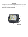
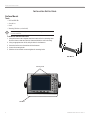
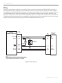
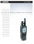
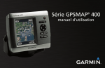
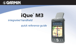
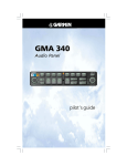
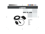
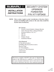
GPSMAP
2006/2010
& GPS 17
®
installation instructions
INSTALLATION INSTRUCTIONS
© Copyright 2005 Garmin Ltd. or its subsidiaries
Garmin International, Inc.
1200 East 151st Street,
Olathe, Kansas 66062, U.S.A.
Tel. 913/397.8200 or 800/800.1020
Fax 913/397.8282
Garmin (Europe) Ltd.
Unit 5, The Quadrangle,
Abbey Park Industrial Estate,
Romsey, SO51 9DL, U.K.
Tel. 44/0870.8501241
Fax 44/0870.8501251
Garmin Corporation
No. 68, Jangshu 2nd Road,
Shijr, Taipei County, Taiwan
Tel. 886/2.2642.9199
Fax 886/2.2642.9099
All rights reserved. Except as expressly provided herein, no part of this manual may be reproduced, copied, transmitted, disseminated, downloaded, or stored in any
storage medium, for any purpose without the express prior written consent of Garmin. Garmin hereby grants permission to download a single copy of this manual onto
a hard drive or other electronic storage medium to be viewed and to print one copy of this manual or of any revision hereto, provided that such electronic or printed
copy of this manual must contain the complete text of this copyright notice and provided further that any unauthorized commercial distribution of this manual or any
revision hereto is strictly prohibited.
Information in this document is subject to change without notice. Garmin reserves the right to change or improve its products and to make changes in the content
without obligation to notify any person or organization of such changes or improvements. Visit the Garmin Web site (www.garmin.com) for current updates and
supplemental information concerning the use and operation of this and other Garmin products.
Garmin® is a registered trademark of Garmin Ltd. or its subsidiaries and may not be used without the express permission of Garmin.
Safety Information
WARNING: This product, its packaging, and its components contain chemicals known to the State of California to cause cancer, birth defects, or reproductive harm.
This Notice is being provided in accordance with California’s Proposition 65. If you have any questions or would like additional information, please refer to our Web
site at http://www.garmin.com/prop65.
Limited Warranty
This Garmin product is warranted to be free from defects in materials or workmanship for one year from the date of purchase. Within this period, Garmin will at its
sole option repair or replace any components that fail in normal use. Such repairs or replacement will be made at no charge to the customer for parts or labor,
provided that the customer shall be responsible for any transportation cost. This warranty does not cover failures due to installation errors, abuse, misuse, accident, or
unauthorized alteration or repairs.
THE WARRANTIES AND REMEDIES CONTAINED HEREIN ARE EXCLUSIVE AND IN LIEU OF ALL OTHER WARRANTIES EXPRESS OR IMPLIED OR
STATUTORY, INCLUDING ANY LIABILITY ARISING UNDER ANY WARRANTY OF MERCHANTABILITY OR FITNESS FOR A PARTICULAR PURPOSE,
STATUTORY OR OTHERWISE. THIS WARRANTY GIVES YOU SPECIFIC LEGAL RIGHTS, WHICH MAY VARY FROM STATE TO STATE.
IN NO EVENT SHALL GARMIN BE LIABLE FOR ANY INCIDENTAL, SPECIAL, INDIRECT OR CONSEQUENTIAL DAMAGES, WHETHER RESULTING
FROM THE USE, MISUSE, OR INABILITY TO USE THIS PRODUCT OR FROM DEFECTS IN THE PRODUCT. Some states do not allow the exclusion of
incidental or consequential damages, so the above limitations may not apply to you.
Garmin retains the exclusive right to repair or replace the product or offer a full refund of the purchase price at its sole discretion. SUCH REMEDY SHALL BE
YOUR SOLE AND EXCLUSIVE REMEDY FOR ANY BREACH OF WARRANTY.
Online Auction Purchases: Products sold through online auctions are not eligible for rebates or other special offers from Garmin. Online auction confirmations are
not accepted for warranty verification. To obtain warranty service, an original or copy of the sales receipt from the original retailer is required. Garmin will not replace
missing components from any package purchased through an online auction.
International Purchases: A separate warranty is provided by international distributors for units purchased outside the United States. This warranty is provided by
the local in-country distributor and this distributor provides local service for your unit. Distributor warranties are only valid in the area of intended distribution. Units
purchased in the United States or Canada must be returned to the Garmin service center in the United Kingdom, the United States, Canada, or Taiwan for service.
To obtain warranty service, contact your local Garmin authorized dealer or call Garmin Product Support for shipping instructions and an RMA tracking number. The
product should be securely packed with the tracking number clearly written on the outside of the package. The product should then be sent, freight charges prepaid, to
any Garmin warranty service station. A copy of the original sales receipt is required as the proof of purchase for warranty repairs.
July 2005
2
Part Number 190-00228-01 Rev.F
Printed in Taiwan
GPSMAP 2006C/2010C & GPS 17
INSTALLATION INSTRUCTIONS
INTRODUCTION
The GPSMAP 2006C/2010C Multi-Function Display (MFD) and GPS 17 must be properly installed according to the following instructions for
the best possible performance. To complete the installation, you need the appropriate fasteners, tools, and mounts listed in each section. These
items are available at most marine dealers. Always wear safety goggles, ear protection, and a dust mask when drilling, cutting, or sanding.
When drilling or cutting, always check first to see what is on the opposite side of the surface. Mount the GPSMAP 2006C/2010C in a location
that provides a clear, glare-free view of the display and easy operation of the controls. If you experience difficulty installing the unit, contact
Garmin Product Support or seek the assistance of a professional installer.
Mounting Knob
Bail Mount
Mounting Holes
GPSMAP 2010C Shown
GPSMAP 2006C/2010C & GPS 17
3
INSTALLATION INSTRUCTIONS
INSTALLATION INSTRUCTIONS
Surface Mount
Tools
•
•
•
•
Drill and Drill Bit
Screwdriver
Pencil
Mounting Hardware (not included)
NOTE: Mounting hardware (fasteners) not included. Mounting holes are 5/16"
(7.9 mm) in diameter.
To install the Bail Mount and unit:
1. Using the bail mount as a template, mark the location of the four mounting holes.
Be sure to leave at least two inches of clearance behind the unit for the wiring.
2. Using an appropriate size drill bit, drill pilot holes for the fasteners.
3. Secure the bail mount to the surface with the fasteners.
4. Loosen the mounting knobs.
5. Slide the unit into the bail mount and tighten the mounting knobs.
Bail Mount
Mounting knobs
Bail mount
4
GPSMAP 2006C/2010C & GPS 17
INSTALLATION INSTRUCTIONS
Flush Mount
Tools
•
•
•
•
•
•
•
•
•
•
Flush Mount Template
Jig saw
Masking tape
Scissors
Drill
Drill bits—1/8" (3 mm) and 3/8" (6 mm)
1/16" (2 mm) Allen (Hex) wrench
Sockets or wrenches
Hammer
Center punch
Flush Mount
To flush mount the GPSMAP 2006C/2010C:
1.
2.
3.
4.
5.
Trim the Flush Mount Template and tape it in the location you want.
Using the center punch, indent the center of each mounting hole location.
Using an 1/8” (3 mm) drill bit, drill the four mounting holes.
Using a 3/8” (6 mm) drill bit, drill a hole for a location to begin cutting the mounting surface.
Using the Jig Saw, cut the mounting surface along the inside of the dashed line indicated on the template. Use a file and sandpaper to
refine the size of the hole. Be very careful when cutting this hole. There is only a small amount of clearance between the case
molding and the mounting holes.
6. Install the four mounting studs into unit by screwing the shorter, threaded section into the back of the unit. Use a 1/16” (2 mm) Allen
wrench to tighten the mounting studs until the stop contacts the case. Be careful not to overtighten as this may damage the
mounting stud! The studs have a reusable thread-locking patch
pre-applied from the factory.
7. Place the unit in position in the cut-out of the mounting surface.
8. Place washers over the mounting studs, then thread on one
hex nut per mounting stud. Tighten all four until the unit is snug
against the mounting surface. Install and tighten the second hex
nut set on all four mounting studs to lock the first set in place.
TRIM TEMPLATE ALONG THIS LINE TO AID FITTING
230mm
GPSMAP 2010/2010C/3010C
CUT MOUNTING SURFACE
ALONG INSIDE OF THIS LINE
Be very careful when cutting this hole,
there is only a small amount of clearance�
between the unit and the Mounting Hole.
UNIT OUTLINE
Flush Mounting the GPS
1. Trim the Flush Mount Template and tape in the desired location.
2. Using the Center Punch, indent the center of each Mounting Hole location.
3. Using an 1/8” (3mm) drill bit, drill the four Mounting Holes. (Drilling the mounting
holes before cutting the hole for the unit will allow for an easier installation.)
4. Using a 3/8” (6mm) drill bit, drill a hole for a location to begin cutting the mounting
surface.
5. Using the Jig Saw, cut the mounting surface along the inside of the dashed line
indicated on the template. Be very careful when cutting this hole, there is only a small
amount of clearance between the case molding and the Mounting Holes.
6. Install the four Mounting Studs into unit by screwing the shorter, threaded section
into the back of the unit. Use a 1/16” (2mm) Allen Wrench to tighten the Mounting Studs
until the stop contacts the case. Be careful not to overtighten as this may damage the
Mounting Stud! The studs have a reusable thread-locking patch pre-applied from the factory.
7. Place the unit in position in the cut out of the mounting surface.
8. Place washers over the Mounting Studs, then thread on one Hex Nut per Mounting Stud.
Tighten all four until the unit is snug against the mounting surface.
Install and tighten the second Hex Nut on all four Mounting Studs to lock the first one
in place.
208mm
DRILL A 3/8" HOLE.
BEGIN CUTTING HERE
Stud
Washer Hex nuts
Mounting surface
Flush Mount Template
GPSMAP 2006C/2010C & GPS 17
5
INSTALLATION INSTRUCTIONS
Installing the GPS 17
The GPS 17 can be flush mounted or installed on any standard 1" O.D. (Outer
Dimension), 14 threads-per-inch marine mount. When mounting the GPS 17, the
cable can be run externally or through the mounting panel or through the center of
the marine mount.
The GPS 17 connects to the 18-pin Power/Data Cable on the GPSMAP
2006C/2010C and provides the GPS/WAAS signal for the unit. If two or more
GPSMAP 2006C/2010C units are installed, only one GPS 17 needs to be installed.
ABOVE - BEST
Radar
3'
BELOW - OK
To ensure the best reception, mount the GPS 17 in a location that has a clear,
unobstructed view of the sky in all directions. Avoid mounting the GPS 17 where
it is shaded by the boat’s superstructure, a radome antenna, or mast. Sailboat
users should avoid mounting the unit high on the mast to prevent inaccurate
speed readings caused by excessive heeling. The unit provides more stable
readings if it is located nearer to water level. Mount the GPS 17 at least 3 ft
away from (preferably above) the path of any radar beam or a VHF radio
antenna. Temporarily secure the unit in the desired mounting location and test for
correct operation. With correct operation verified, permanently mount the unit. If
interference with other electronics is experienced, try a different location.
VHF Radio Antenna
Radar
NOTE: Mount the antenna at least 3 ft away from
(preferably above) the path of any radar beam or a
VHF radio antenna.
BETTER
GOOD
BEST
SS JAYHAWK
EMI
EMI (Electromagnetic Interference)
from engine components
NOTE: Never paint the GPS 17 or clean it with harsh solvents.
Signal Interference
To flush mount the GPS 17:
1. Cut out the Mounting Template provided on page 11, and tape it on the selected mounting location.
2. Mark the center of each mounting hole by tapping the end of a center punch or pointed object with a hammer. If the cable is going to be
installed through the mounting panel, mark the center of the additional hole.
3. Drill the holes using the appropriate drill bit(s).
4. Align the GPS 17 over the mounting holes and fasten using M4 screws. The mounting threads in the GPS 17 are 8.10 mm deep. Do not
use screws that thread into the GPS 17 deeper than 8 mm, or the case may be damaged.
Bottom of GPS 17
The GPS 17 can be installed with the coax through the panel
or on the outside of the unit. If the coax is run through the
panel, seal the outside exit area with marine sealant.
Mounting holes
6
GPSMAP 2006C/2010C & GPS 17
INSTALLATION INSTRUCTIONS
To attach the enclosed pole mount to the GPS 17:
1. Thread the cable though the pole mount.
2. Align the tab on the mount to the notch on the GPS 17.
3. Use the enclosed screws to secure the mount to the base.
Attaching the Pole Mount to the GPS 17
To mount the GPS 17 with cable outside mount:
1. Place the cable in the vertical slot along the side of the base of
the unit.
2. Screw the GPS 17 onto the mount. DO NOT overtighten the
head. It is possible to over tighten the unit and cut the cable.
3. With the GPS 17 and mount installed, fill the remaining gap in
the cable exit with a marine sealant.
4. Route the cable away from sources of electronic interference.
To mount the GPS 17 with cable through mount:
1. Position the mount in the desired location and mark the
approximate center of the mount.
2. Drill a hole large enough for the cable to pass through.
3. Slide the cable through the mount and screw the GPS 17 onto
the mount.
4. Fasten the mount to the boat.
5. Route the cable away from sources of electronic interference.
Attaching the GPS 17 to a Pole Mount
Align notch
Cable run externally
Cable run internally
GPSMAP 2006C/2010C & GPS 17
7
INSTALLATION INSTRUCTIONS
Wiring
There are two wiring diagrams provided for you convenience. The first is a simple hook-up showing the GPSMAP 2006/2010 (using the 18pin wiring harness), the GPS 17 and the alarm circuit. The Alarm does not have to be wired for the unit to function. The second is a complete
wiring diagram showing the GPSMAP 2006/2010 (using the 18-pin wiring harness) interfacing with a variety of different equipment. The extra
5-pin wiring harness that came with the unit is intended for future interfacing features and does not require connection. Refer to the wiring
diagram that will best suite your needs. Make sure that all connections are good. For extra lengths of wire, 24 AWG (unless otherwise noted on
wiring diagram), shielded, twisted-pair wiring is recommended. We advise soldering all connections and sealing the connection with heat shrink
tubing. If you experience difficulty wiring the unit, please contact an installation professional in your area.
GARMIN
GPSMAP 2006/2010
ACCESSORY ON
DC INPUT
WIRE
COLOR
WIRE
COLOR
ORANGE
RED
5A
+
ALARM
YELLOW
BLACK
PORT 4 OUT
PORT 4 IN
GREEN
WHITE
YELLOW
RED
ON
POWER
SHIP'S BATTERY
10-32 VOLTS
ALARM
SEE NOTE
GROUND
1A
18 AWG
GARMIN GPS 17
GPS SENSOR
18 AWG
-
BLACK
GROUND
BLUE
WHITE
COM 1 IN
COM 1 OUT
NOTE:
THE ALARM OUTPUT CAN BE USED TO DRIVE A LAMP, HORN, OR BOTH.
MAXIMUM CURRENT IS 100 MILLIAMPS. A SWITCH OR RELAY CAN BE USED
TO SELECT BETWEEN VISUAL AND AUDIBLE ALERTS, IF REQUIRED
Diagram 1 - Basic Hook-up
8
GPSMAP 2006C/2010C & GPS 17
INSTALLATION INSTRUCTIONS
+
SHIP'S BATTERY
10-32 VOLTS
-
GARMIN GSD 20
SOUNDER MODULE
(SEE GSD 20
INSTALL INSTRUCTIONS)
(-)
(-)
(-)
4. A GARMIN SOUNDER UNIT (OTHER THAN GSD 20) CAN PROVIDE WATER DEPTH, WATER TEMPATURE,
AND SPEED VIA NMEA DATA FOR DISPLAY ON THE GPSMAP 2006/2010.
Diagram 2 - Complete Interface
GPSMAP 2006C/2010C & GPS 17
9
INSTALLATION INSTRUCTIONS
Final Wiring Connection
Once all the wiring is complete, plug the 18-pin harness into the center connector on the backside of the GPSMAP 2006/2010. The 5-pin port
on the right side is intended for future interfacing features and does not require connection at this time.
With power applied to the circuit, you may test the installation by pressing the POWER
Manual for steps on initializing the receiver.
18-Pin Connector
10
key on the front of the unit. See the Owner’s
5-Pin Connector
(for future use)
GPSMAP 2006C/2010C & GPS 17
INSTALLATION INSTRUCTIONS
FLUSH MOUNT DRILLING TEMPLATE
Drill using a
11/64” or 4.5 mm
drill bit
Dill this 3/4” or 19 mm
hole if the coax is
going to be installed
through the mounting
panel
GPSMAP 2006C/2010C & GPS 17
11
© Copyright 2005 Garmin Ltd. or its subsidiaries
Garmin International, Inc.
1200 East 151st Street, Olathe, Kansas 66062, U.S.A.
Garmin (Europe) Ltd.
Unit 5, The Quadrangle, Abbey Park Industrial Estate, Romsey, SO51 9DL, U.K.
Garmin Corporation
No. 68, Jangshu 2nd Road, Shijr, Taipei County, Taiwan
www.garmin.com
Part Number 190-00228-01 Rev. F