1
Apollo
Model SL30 NAV/COMM
Installation Manual
August 2003
560-0404-03a
2003 Garmin AT, Inc. All rights reserved.
Printed in the USA
No part of this document may be transmitted, reproduced, or copied in any form or by any means
without the prior written consent of Garmin AT, Inc. Due to Garmin AT’s commitment to
constantly improve the quality and performance of our products, information contained in this
document is subject to change without notice.
Garmin AT, Inc. and Apollo are registered trademarks of Garmin AT, Inc.
Garmin AT, Inc.
PO Box 13549
Salem, OR 97309
Phone 503.581.8101
800.525.6726
In Canada 800.654.3415
Fax: 503.364.2138
2345 Turner Rd. SE
Salem, OR 97302
USA
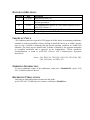
HISTORY OF REVISIONS
Revision
-01
Date
11/16/99
2/10/00
02
8/2/01
03
03a
2/21/02
8/26/03
Description
Initial release (EN6278).
Added interface wiring diagrams, refined post installation
checkout procedures.
New mounting tubes, dual SL30’s, DST info to Apollo GX (EN
6949). SW Version 1.2
Added helicopter environmental qualification information.
Changed logo and added JTSO information.
IMPORTANT NOTE
“The conditions and tests required for TSO approval of this article are minimum performance
standards. It is the responsibility of those desiring to install this article on or within a specific
type or class of aircraft to determine that the aircraft operating conditions are within TSO
standards. The article may be installed only if further evaluation by the applicant documents
an acceptable installation and is approved by the Administrator.” Follow installation
recommendations as noted in AC20-67B, Airborne VHF Communications Equipment
Installations.
Source: FAA TSO-C34e, TSO-C36e, TSO-C37d, TSO-C38d, TSOC40c, TSO-C66c, and TSO-C128.
ORDERING INFORMATION
To receive additional copies of this publication, order part # 560-0404-03a, Apollo SL30
NAV/ COMM Installation Manual.
REFERENCE PUBLICATIONS
Following are other publications referenced in this guide.
Apollo SL30 NAV/ COMM Operation Manual, order part # 560-0403-xx.
NOTES
Table of Contents
TABLE OF CONTENTS
SECTION 1 - INTRODUCTION ................................................................................................ 1
ABOUT THIS MANUAL ..................................................................................................................... 1
APOLLO SL30 DESCRIPTION ............................................................................................................ 1
FEATURES ........................................................................................................................................ 2
GENERAL FEATURES ..................................................................................................................................................2
NAVIGATION RADIO FEATURES .................................................................................................................................2
COMM RADIO FEATURES ...........................................................................................................................................3
PHYSICAL SPECIFICATIONS ........................................................................................................................................3
NAV RADIO PERFORMANCE SPECIFICATIONS ...........................................................................................................3
COMM RADIO PERFORMANCE SPECIFICATIONS..........................................................................................................3
SYSTEM INTERFACES........................................................................................................................ 4
NAVIGATION RECEIVER .............................................................................................................................................4
COMM TRANSCEIVER .................................................................................................................................................4
SERIAL INTERFACE ....................................................................................................................................................4
REGULATORY COMPLIANCE ............................................................................................................. 4
UNPACKING THE EQUIPMENT ........................................................................................................... 5
PACKAGE CONTENTS ....................................................................................................................... 5
OTHER REQUIRED MATERIALS......................................................................................................... 6
SPECIAL TOOLS REQUIRED............................................................................................................... 6
LICENSE REQUIREMENTS ................................................................................................................. 7
SECTION 2 - INSTALLATION.................................................................................................. 9
PRE-INSTALLATION INFORMATION................................................................................................... 9
INSTALLATION OVERVIEW ............................................................................................................... 9
INSTALLATION CONSIDERATIONS ..................................................................................................... 9
MOUNTING CONSIDERATIONS ....................................................................................................................................9
MINIMUM SYSTEM CONFIGURATION..........................................................................................................................9
EQUIPMENT MOUNTING ................................................................................................................. 10
MOUNTING TUBE INSTALLATION .............................................................................................................................10
UNIT INSERTION.......................................................................................................................................................12
UNIT REMOVAL .......................................................................................................................................................12
ELECTRICAL CONNECTIONS ........................................................................................................... 14
POWER .....................................................................................................................................................................14
AVIONICS OUTPUTS .................................................................................................................................................14
SERIAL INTERFACE ..................................................................................................................................................14
SPEAKER AND HEADPHONE OUTPUTS ......................................................................................................................14
MICROPHONE INPUTS ...............................................................................................................................................15
TRANSMIT KEY INPUT..............................................................................................................................................15
INTERCOM SELECTOR SWITCH .................................................................................................................................15
REMOTE FLIP/FLOP INPUT........................................................................................................................................15
ANTENNA INSTALLATION AND CONNECTIONS ............................................................................... 15
COMM AND NAV ANTENNAS....................................................................................................................................15
USE OF SPLITTER AND COMBINER ............................................................................................................................16
EQUIPMENT INTERFACE ................................................................................................................. 17
LIMITATIONS ON USING A COMPOSITE SIGNAL .............................................................................. 33
LIMITATIONS ON DISTANCE, SPEED, AND TIME INFORMATION....................................................... 33
POST INSTALLATION CHECKOUT .................................................................................................... 33
MOUNTING / WIRING CHECK ...................................................................................................................................33
Apollo SL30 Installation Manual
i
Table of Contents
SETUP AND CHECKOUT............................................................................................................................................ 33
FINAL SYSTEM CHECK ............................................................................................................................................ 37
INSTRUCTIONS FOR CONTINUED AIRWORTHINESS ..........................................................................40
SECTION 3 - SPECIFICATIONS .............................................................................................41
ELECTRICAL ...................................................................................................................................41
PHYSICAL .......................................................................................................................................41
ENVIRONMENTAL ...........................................................................................................................41
AVIONICS OUTPUTS ........................................................................................................................42
NAV RECEIVER PERFORMANCE .....................................................................................................43
VOR ....................................................................................................................................................................... 43
LOCALIZER .............................................................................................................................................................. 43
GLIDESLOPE ............................................................................................................................................................ 44
OBS RESOLVER ...................................................................................................................................................... 44
COMPOSITE OUTPUT................................................................................................................................................ 44
COMM RECEIVER PERFORMANCE ...................................................................................................45
COMM TRANSMITTER PERFORMANCE .............................................................................................45
INTERCOM PERFORMANCE ..............................................................................................................46
CONTROL INPUTS ............................................................................................................................46
ANTENNA REQUIREMENTS ..............................................................................................................46
COMM ANTENNA ..................................................................................................................................................... 46
NAV ANTENNA....................................................................................................................................................... 46
SERIAL INTERFACE .........................................................................................................................47
REAR CONNECTOR PINOUT .............................................................................................................47
SECTION 4 - LIMITATIONS ...................................................................................................49
INSTALLATION ................................................................................................................................49
COMPUTATION RATES ....................................................................................................................49
OPERATIONAL.................................................................................................................................49
APPENDIX A - TROUBLESHOOTING ..................................................................................51
CONTACTING THE FACTORY FOR ASSISTANCE ................................................................................52
APPENDIX B - PERIODIC MAINTENANCE ........................................................................53
VOR CHECKS .................................................................................................................................53
EQUIPMENT CALIBRATION ..............................................................................................................53
REFERENCE OSCILLATOR (COMM ONLY) ................................................................................................................ 53
CLEANING THE FRONT PANEL.........................................................................................................53
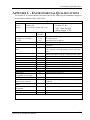
APPENDIX C - ENVIRONMENTAL QUALIFICATIONS...................................................55
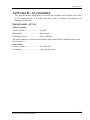
APPENDIX D - ACCESSORIES ...............................................................................................57
FROM GARMIN AT, INC. .................................................................................................................57
APPENDIX E - SERIAL INTERFACE SPECIFICATIONS .................................................59
INPUT COMMANDS ..........................................................................................................................59
OUTPUT MESSAGES ........................................................................................................................59
DATA FORMAT................................................................................................................................60
DEFAULT MESSAGE OUTPUT ..........................................................................................................60
MESSAGE FORMATS........................................................................................................................60
ii
Apollo SL30 Installation Manual
Table of Contents
MESSAGE DEFINITIONS .................................................................................................................. 61
INPUT MESSAGES .....................................................................................................................................................61
REMOTE VOR LIST ..................................................................................................................................................62
REMOTE LOCALIZER LIST ........................................................................................................................................64
REQUEST DATA OUTPUT ..........................................................................................................................................66
SET ACTIVE VOR/LOC FREQUENCY AND RECEIVER FUNCTION .............................................................................67
SET STANDBY VOR/LOC FREQUENCY AND RECEIVER FUNCTION ..........................................................................67
SET STANDBY COMM FREQUENCY AND TRANSCEIVER FUNCTION .........................................................................68
SET ACTIVE COMM FREQUENCY AND TRANSCEIVER FUNCTION ............................................................................68
SET NAV AUDIO MODE...........................................................................................................................................69
SET OMNI-BEARING SELECT (OBS) VALUE.............................................................................................................69
DME SENSOR INPUT ................................................................................................................................................70
OUTPUT MESSAGES........................................................................................................................ 70
RESET STATUS .........................................................................................................................................................70
CDI, GSI, AND RELATED FLAGS ..............................................................................................................................71
DECODED OBS SETTING ..........................................................................................................................................72
RADIAL FROM ACTIVE VOR....................................................................................................................................72
RADIAL FROM STANDBY VOR ................................................................................................................................72
DECODED STATION IDENTIFIER................................................................................................................................73
COMMUNICATIONS ERROR .......................................................................................................................................73
NAV RECEIVER STATUS ..........................................................................................................................................74
NAV AUDIO MODE .................................................................................................................................................74
NAV MICROCONTROLLER SOFTWARE VERSION......................................................................................................75
NAV DSP SOFTWARE VERSION ..............................................................................................................................75
ADC DATA OUTPUT ................................................................................................................................................75
COMM TRANSCEIVER STATUS ..................................................................................................................................76
COMM SOFTWARE VERSION.....................................................................................................................................76
Apollo SL30 Installation Manual
iii
Table of Contents
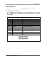
LIST OF TABLES
TABLE 1 - PACKAGE CONTENTS........................................................................................................5
TABLE 2 - COMM INTERFACE CONNECTOR PINOUT ........................................................................47
TABLE 3 - REAR PANEL CONNECTOR PINOUT .................................................................................48
TABLE 4 - TROUBLESHOOTING GUIDE ............................................................................................51
TABLE 5 - DATA OUTPUT REQUESTS ..............................................................................................66
LIST OF ILLUSTRATIONS
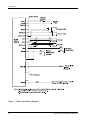
FIGURE 1 - SL30 FRONT PANEL ........................................................................................................2
FIGURE 2 - FULL STACK MOUNTING TUBE SPACING.......................................................................11
FIGURE 3 - CAM LOCK POSITIONING ...............................................................................................12
FIGURE 4 - MOUNTING FRAME ASSEMBLY .....................................................................................13
FIGURE 5 - CABLE ROUTING ...........................................................................................................13
FIGURE 6 - REAR COAX CONNECTOR ASSEMBLY ...........................................................................16
FIGURE 7 - SL30 COMM WIRING DIAGRAM ....................................................................................18
FIGURE 8 - SL30 COMM TYPICAL AUDIO PANEL CONNECTIONS ....................................................19
FIGURE 9 - SL30 NAV POWER AND AUDIO CONNECTIONS ............................................................20
FIGURE 10 – SL30 TO APOLLO GX50/60 CONNECTIONS ................................................................20
FIGURE 11 - SL30 - GX50/60 - MX20 CONNECTIONS ....................................................................21
FIGURE 12 - SL30 NAV TO MID-CONT MD200-306/307...............................................................22
FIGURE 13 - SL30 NAV TO MID-CONT MD200-302/303 CONNECTIONS .......................................23
FIGURE 14 - SL30 NAV AND ACU TO MID-CONT MD200-306/307..............................................24
FIGURE 15 - SL30 NAV TO STEC IND-351A CONNECTIONS ........................................................25
FIGURE 16 - SL30 NAV TO BENDIX/KING KN72/203/204/208/208A/209/209A WIRING .............26
FIGURE 17 - SL30 NAV TO BENDIX/KING KI202/206/525A/KPI552 WIRING...............................27
FIGURE 18 - SL30 NAV TO SANDEL DISCRETE CONNECTIONS .......................................................28
FIGURE 19 - SL30 NAV TO SANDEL SN3308 CONVERTER CONNECTIONS .....................................29
FIGURE 20 - SL30 TO SPERRY RD 550A AND RD650 WIRING .......................................................30
FIGURE 21 - SL30 TO COLLINS 331A-6P, 331A-9G, AND PN-101 WIRING ....................................31
FIGURE 22 - SL30 TO CENTURY NSD 360A AND NSD 1000 WIRING .............................................32
FIGURE 23 - UNIT DIMENSIONS .......................................................................................................42
iv
Apollo SL30 Installation Manual
Introduction
SECTION 1 - INTRODUCTION
ABOUT THIS MANUAL
This manual describes the installation of the Apollo SL30 Nav/Comm units. It is intended for
use by persons certified by the Federal Aviation Administration (FAA) to install aircraft
navigation devices. It includes installation and checkout procedures for the SL30 unit to
standards described in FAA advisory circulars AC 20-67B (for Comm).
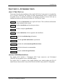
Section 1
Provides an introduction to the Apollo SL30 unit. TSO certification information
is also included in this section.
Section 2
Includes installation and checkout procedures.
Section 3
Includes complete specifications.
Section 4
Includes limitations for the equipment and installation.
Appendix A
Includes troubleshooting information.
Appendix B
Includes periodic maintenance requirements.
Appendix C
Includes the environmental qualification form.
Appendix D
Includes information on accessories.
Appendix E
Includes serial data specifications.
APOLLO SL30 DESCRIPTION
The Apollo SL30 includes a 760-channel VHF Comm transceiver and 200-channel
VOR/LOC/GS navigation receiver with DME display.
The Apollo SL30 is a member of the Apollo slimline series which includes the SL10/15
Audio Selector Panels, SL40 Comm, SL50 GPS, SL60 GPS/Comm, and SL70 Transponder.
Apollo SL30 Installation Manual
1
Introduction
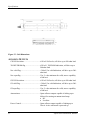
Figure 1 - SL30 Front Panel
FEATURES
GENERAL FEATURES
•
•
•
•
•
•
32 character high-intensity alphanumeric LED display
Sunlight readable full alphanumeric display
Automatic display intensity
Back-lit buttons
200 channel memory (stored alphabetically)
Remote frequency flip-flop input pin
NAVIGATION RADIO FEATURES
•
•
•
•
•
•
•
•
•
•
•
•
2
200 channel Nav with solid state DSP technology
VOR/Localizer and Glideslope receivers
Built-in VOR/Localizer converter
Frequency range:
VOR
108.00 – 117.95 MHz
Localizer 108.00 – 111.95 MHz
Glideslope 328.60 – 335.40 MHz
Digitally decoded OBS setting
Manual selection of back course approach
Automatic display of station ID by decoding Morse code
Interfaces to most CDI (w/resolver), HSI, and autopilot systems
VOR receiver displays To or From radial of the active channel
VOR monitor displays From radial of the standby channel
Back course annunciator output
LOC enable annunciator output
Apollo SL30 Installation Manual
Introduction
•
•
•
Internal RF diplexor
Active and standby flip/flop frequencies
DME tuning and data display
COMM RADIO FEATURES
•
•
•
•
•
•
•
•
•
•
•
•
760 communications channels
Frequency range 118 to 136.975 MHz
Active and standby flip/flop frequencies
Volume control
Tunes to National Weather Service broadcasts
Transmit status indicator
Frequency monitor function (listens to standby while monitoring active)
Emergency channel menu
Squelch test function
Stuck Mic time-out
12 watt audio amplifier
Includes two-place VOX intercom
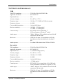
PHYSICAL SPECIFICATIONS
•
•
•
1.3"(H) x 6.25" (W) x 10.5" (D)
Weight 2.25 lbs. (unit only)
Depth 11.452 inches (29.09cm) behind panel, including mounting frame and connectors
NAV RADIO PERFORMANCE SPECIFICATIONS
•
•
•
•
•
•
Input voltage range 10 to 40 VDC
Operating temperature range –20ºC to +55ºC
Certified TSO C34e/JTSO C34e (Glideslope receive)
Certified TSO C36e/JTSO C36e (ILS Localizer receive)
Certified TSO C40c/JTSO 2C40c (VOR receive)
Certified TSO C66c/JTSO 2C66b (DME display)
COMM RADIO PERFORMANCE SPECIFICATIONS
•
•
•
•
•
•
Input voltage range 10 to 40 VDC
Operating temperature range –20ºC to +55ºC
Transmit power 8 watts (Carrier Power)
Certified TSO C37d/JTSO 2C37e (Comm transmitting)
Certified TSO C38d/JTSO 2C38e (Comm receiving)
Certified TSO C128/JTSO 2C128 (stuck mic)
Apollo SL30 Installation Manual
3
Introduction
SYSTEM INTERFACES
NAVIGATION RECEIVER
The SL30 can be installed in several configurations based upon individual requirements. This
includes with or without an external course deviation indicator. The CDI may be discrete,
serial, or composite.
COMM TRANSCEIVER
For standalone installations, the Comm requires connections to:
• a standard Comm antenna
• a microphone (or microphones)
• a speaker or headphone
• power input
These items may be installed dedicated to the SL30 Comm, or by connection to an audio
panel. The system can be configured to mix the NAV audio with the Comm audio if no
external audio panel is used.
SERIAL INTERFACE
•
•
•
DME – Distance Measure Equipment
SL/GX – GPS products
MX – Multi-Function Display
REGULATORY COMPLIANCE
The Apollo SL30 is designed and tested to meet the following TSOs/JTSOs:
FAA TSO-C37d/JTSO 2C37e for Comm transmit
FAA TSO-C38d/JTSO 2C38e for Comm receive
FAA TSO-C128/JTSO 2C128 for unintentional transmission (stuck mic)
FAA TSO-C34e/JTSO C34e for ILS Glideslope receive
FAA TSO-C36e/JTSO C36e for ILS Localizer receive
FAA TSO-C40c/JTSO 2C40c for VOR receive
FAA TSO-C66c/JTSO 2C66b for DME display
The Apollo SL30 complies with the FCC requirements specified in:
CFR 47, Part 87, Aviation Services, Subpart D, Technical Requirements
The Apollo SL30 complies with the FCC requirements specified in:
CFR 47, Part 15, Radio Frequency Devices, Subpart B, Unintentional Radiators
The Apollo SL30 software is designed and tested to RTCA/DO-178B, level C and ED-12B,
level C.
Note: Unauthorized changes or modifications to the SL30 may void the
compliance to required regulatory agencies and authorization for continued
equipment usage.
4
Apollo SL30 Installation Manual
Introduction
UNPACKING THE EQUIPMENT
Carefully unpack the equipment. Visually inspect the package contents for any evidence of
shipping damage. Retain all shipping containers and packaging material in case reshipment is
necessary.
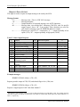
PACKAGE CONTENTS
As shipped from the Garmin AT factory, the Apollo SL30 package includes most items
necessary for installation other than supplies normally available at the installation shop, such
as wire and cable ties, and required input and output equipment. The standard items included
in the package are listed in Table 1.
Table 1 - Package Contents
Part #
430-6040-3xx
Install kits
162-1575
162-1577
162-1008
202-0001
204-0037
204-2100
221-0400
224-0404
245-0027
310-5181-xx or
310-5197-xx
310-5192-xx
998-0048
Manual kits
560-0403-xx
560-0404-xx
561-0262-xx
Accessories
115-0007
S712-0007-012
Description
SL30 NAV/COMM
Part number: 424-2006-300
15-pin d-sub connector shell
37-pin d-sub connector shell
Right angle coax plug
Cable tie
Edge grommet
Shoulder bushing
4-40 x 1/4 SS pan head Phillips machine screw with lock
washer
4-40 x 1/4 SS flat head Phillips machine screw
Crimp contact for d-sub, 20 to 24 awg wire
Mounting frame
NOTE: Only 310-5197-xx is qualified for helicopter use.
Connector mounting plate
3/32 hex driver
Part number: 564-0064-300
SL30 User’s Manual
SL30 Installation Manual
SL30 Quick Reference Guide
NAV signal splitter/combiner
Internal 3 amp slow blow fuse
Qty
1
1
1
2
2
6"
4
8
4
50
1
1
1
-4xx
1
1
1
Optional
Optional
Note: Package contents may vary depending on how the unit is ordered.
Apollo SL30 Installation Manual
5
Introduction
OTHER REQUIRED MATERIALS
The SL30 is intended for use with standard aviation accessories. External devices required for
various installations are listed below. Depending upon the installation, this will include items
such as:
• back course annunciator
• a CDI or HSI
• a Comm antenna
• NAV antenna
• NAV antenna splitter (if dual SL30)
• a microphone(s)
• a speaker or headphone
• audio panel
SPECIAL TOOLS REQUIRED
Crimp Tool
A crimp tool meeting MIL specification M22520/1-01 and a positioner/locater are required to
ensure consistent, reliable crimp contact connections for the rear 15-pin and 37-pin
connectors. These tools are available from:
For pin P/N 245-0022
Astro Tool Corp.
21615 SW TV Highway
Beaverton, OR 97006
Crimp tool:
Positioner:
For pin P/N 245-0027
ITT Cannon
1851 E. Deere Ave.
Santa Ana, CA 92705-6500
Insertion tool:
Regular duty Crimp tool:
Regular duty Locator tool:
Heavy duty Crimp tool:
Heavy duty Locator tool:
6
Phone (503) 642-9853
Fax (503) 591-7766
Astro Tool part #615708
Astro Tool part #616356
Phone (714) 261-5300
Fax
(714) 575-8324
ITT part # 274-7006-000 (Desc. CIET-20HD)
ITT part #995-0001-585 (Desc. M22520/1-01)
ITT part #995-0001-244 (Desc. TH25)
ITT part #995-0001-584 (Desc. M22520/2-01)
ITT part #995-0001-604 (Desc. M22520/2-08)
Apollo SL30 Installation Manual
Introduction
LICENSE REQUIREMENTS
An aircraft radio station license may be required for operation of the SL30 Comm transmitter
once installed in the aircraft. An application must be submitted on FCC Form 404, Form 605
or later revised application, which may be obtained from the FCC in Washington, DC, or any
of its field offices. Procedures for applications are in CFR 47, Part 87, Aviation Services,
Subpart B, Applications and Licenses.
Apollo SL30 Installation Manual
7
Introduction
NOTES
8
Apollo SL30 Installation Manual
Installation
SECTION 2 - INSTALLATION
This section describes the installation of the SL30 including mounting, wiring, and
connections. A post installation check-out procedure is included at the end of this section.
PRE-INSTALLATION INFORMATION
Always follow good avionics installation practices per FAA Advisory Circulars (AC) 43.131B, 43.13-2A, and AC 20-67B, or later FAA approved revisions of these documents.
Follow the installation procedure in this section as it is presented for a successful installation.
Read the entire section before beginning the procedure. Perform the post installation checkout before closing the work area in case problems occur.
INSTALLATION OVERVIEW
A successful installation should start with careful planning including determination of
mounting location for the SL30, antenna mounting, connections to microphones, speakers,
and headphones, cable routing, and other required modifications. Once the mounting location
has been determined, prepare the mounting frame for installation. It may be easier to complete
the wiring harness and attach the connectors to the mounting frame before installing the
mounting frame.
INSTALLATION CONSIDERATIONS
MOUNTING CONSIDERATIONS
The SL30 is designed to mount in the avionics stack in the aircraft instrument panel within
easy view and reach of the pilot. The standard package includes a mounting frame for ease of
mounting, connections, and service of the unit. Allow an additional one-inch clearance to the
rear of the mounting frame for connectors and cables.
For typical installations, the SL30 does not require external cooling. When mounting the unit,
leave a clearance of 1/8 to 1/4 inch between avionics to allow for air circulation.
MINIMUM SYSTEM CONFIGURATION
VFR Installation
VFR installation need only include an SL30 with power, audio, and antenna connections.
Without an external CDI, no glideslope information is obtainable. However, the unit will
maintain full VOR and Localizer functionality including an internal CDI display.
IFR VOR/LOC Installation
IFR installation requires:
• SL30
• External CDI/HSI indicator that meets the following criteria:
1. The course deviation indicator shall have an input impedance of 1 k ohm ± 10% and a
deflection sensitivity of 150 mV ± 10% for full scale deflection.
2. The valid flag shall have an input impedance of 1 k ohms ± 10%.
Apollo SL30 Installation Manual
9
Installation
3. The valid flag sensitivity shall be 125 mV ± 10% for the flag to leave the stop and
260 mV ± 10% maximum for flag to be fully concealed.
4. The To/From flag shall have an input impedance of 200 ohms ± 10% and a sensitivity
of ± 40 mV ± 15% at 25oC with flag fully in view.
5. The OBS resolver should be compatible with a standard 6-wire OBS interface:
H ...........Reference output high
C............Reference output low
D ...........S1 COS input high
E............S3 COS input low
F ............S4 SIN input high
G ...........S2 SIN input low
Any electrical zero crossing will work because the SL30 will calibrate out any errors.
Glideslope Installation
Glideslope installation requires:
• SL30
• External non-numeric glideslope indicator that meets the following criteria:
1. The glideslope deviation shall have an input impedance of 1 k ohm ± 10% with a
deflection sensitivity of 150 mV ± 10% for full scale deflection.
2. The glideslope valid flag shall have an input impedance of 1 k ohm ± 10%.
3. The glideslope valid flag sensitivity shall be 125 mV ± 10% for the flag to leave the
stop, and 260 mV ± 10% maximum for flag to be fully concealed.
Helicopter Requirements
The SL30 is qualified for helicopter installation with certain mount tube and SL
configurations (see Section 4 – Limitations).
EQUIPMENT MOUNTING
Once the cable assemblies have been made, attach the 15- and 37-pin d-sub and coaxial cable
connectors to the rear connector mounting plate and the mounting frame as illustrated in
Figure 4 and Figure 5. Route the wiring bundle as appropriate. The rear connector plate
should be attached to the mounting frame before installing the frame in the instrument panel.
The rear connector plate can be used to tie down the cable assemblies. Use the supplied edge
guard to protect the cable from sharp edges. Connect the shield grounds directly to the
connector mounting plate.
Once the cable assemblies are complete and the connectors are attached to the mounting
frame, install the mounting frame assembly in the instrument panel as illustrated in Figure 2.
Be sure to use low-profile head screws in the side of the mounting frame so the unit will slide
in and out freely. Attach the front of the mounting frame to the instrument panel. Use support
brackets to attach the rear of the frame to the aircraft.
MOUNTING TUBE INSTALLATION
Care must be taken when installing the mounting tube to ensure you can properly insert and
secure the unit. There must be a minimum vertical spacing of 0.040 inches between units to
prevent interference with the cam locking mechanisms. Mounting tubes with clearance
10
Apollo SL30 Installation Manual
Installation
dimples help maintain the proper clearance. The mounting tube must be installed with the
clearance dimples pointing up.
The mounting tube should be flush to the instrument panel and allow sufficient clearance for the
back of the bezel of the unit to mount flush to the mounting tube. Sufficient clearance must exist
in the instrument panel opening to allow ease of insertion and removal of the unit. If the back
of the unit bezel does not mount flush to the mounting tube, the connector may not
engage fully.
Figure 2 - Full Stack Mounting Tube Spacing
Secure the mounting tube to the instrument panel structure. Mounting screw heads must not
protrude into the mounting tube. Be sure to use the appropriate screws so the unit will slide in
and out freely. The screws attaching the mounting tube to the instrument panel structure must
not interfere with the insertion of the unit. Failure to prevent interference will result in
damage to the unit or prevent its insertion. Take care that the mounting tube is not distorted
when it is attached to the instrument panel and structural supports. Shims may be necessary to
properly install the mounting tube. If the mounting tube is distorted out of square, the unit may
either bind when being inserted or the cam lock may not engage.
Apollo SL30 Installation Manual
11
Installation
UNIT INSERTION
Position the cam lock as shown below. The front lobe of the cam should be vertical. The cam
lock mechanism should be fully unscrewed (turned counter-clockwise). Slide the unit into the
frame. Turn (clockwise) and carefully hand-tighten (4 in-lb max.) the cam lock mechanism
using only the 3/32" hex driver provided in the installation package. Using a larger tool than
the one provided makes it easy to exceed the allowable torque on the cam lock resulting in
damage to the unit. The unit will be pulled into the frame securing the unit and the connectors
when fully engaged. Do NOT overtighten. The back of the bezel must be flush to the
mounting tube. If the cam lock is hard to turn or the unit does not seat fully, the unit is
probably binding and the mounting tube should be checked.
Figure 3 - Cam Lock Positioning
UNIT REMOVAL
To remove the unit from the mounting frame, turn the screw counter-clockwise with the hex
driver to unscrew the cam lock mechanism. The unit will begin to pull away from the
mounting tube. Turn the screw until slight resistance is felt and then pull the unit from the
frame. Do not exert excessive turning force at the end of the cam lock travel or the unit
may be damaged. With the cam lock fully disengaged, pull the unit straight out holding onto
the sides of the bezel. It is not recommended that you pull the unit out by the rotary knobs. No
special extraction tools are required, if the mounting tube is properly installed.
12
Apollo SL30 Installation Manual
Installation
Figure 4 - Mounting Frame Assembly
Figure 5 - Cable Routing
Apollo SL30 Installation Manual
13
Installation
ELECTRICAL CONNECTIONS
The SL30 installation kit includes 15- and 37-pin d-sub shells and crimp contacts. The crimp
contacts are specified for 20 to 24 awg wire. Make the crimp connections with a crimp tool as
specified on page 6. All wires should be 20 to 24 AWG unless otherwise specified. Wiring
diagrams are included in this section.
POWER
The SL30 requires two power connections, one for the Nav side of the unit, the other for the
Comm. Make the power connections to the unit using 20 awg wire.
The Comm power input is internally fused at 7 amps. A separate 5 amp circuit breaker or
fuse should be installed for downline overload or short circuit protection.
The NAV internal fuse is 3 amps. A separate 2 amp circuit breaker or fuse should be installed
for downline overload or short circuit protection.
Note: Circuits should be protected in accordance with guidelines in AC 43.13-1B,
chapter 11, section 4.
Warning
When connecting power to the unit, reversing the polarity of the connection will
blow the internal fuse. The internal fuse requires replacement at the factory or
factory authorized repair center.
AVIONICS OUTPUTS
The SL30 includes a complete avionics interface for resolvers, CDI/HSI indicators, autopilot,
and back course annunciator. These outputs are to be connected as appropriate for the
particular installation. The CDI/HSI outputs may be connected to a dedicated CDI or HSI or
to a shared indicator using an appropriate switching relay, such as an Apollo ACU. The
avionics outputs available are listed in the Avionics Outputs specification on page 42.
Connect the annunciator outputs as necessary.
SERIAL INTERFACE
The SL30 includes an RS-232 serial port for making optional connections. The serial port can
be used for connecting to:
• Resolvers, indicators, or electronic flight instruments that accept serial data
• GX series units for Comm/NAV frequency transfers from the database
• MX20 to display VOR data on a map and database interface
• RMI/DME control box allows DME tuning, DME display, and OBI output
When making connections to the SL30, use a three conductor shielded cable. Make RxD,
TxD, and signal ground connections to the 37-pin connector. Connect the shield(s) to the rear
of the mounting frame on the connector plate. The shield leads must be < 1.25 inches.
Complete serial interface specifications are included in Appendix E – Serial Interface
Specifications.
SPEAKER AND HEADPHONE OUTPUTS
Connect the speaker and headphones to the output pins on the rear connector.
14
Apollo SL30 Installation Manual
Installation
MICROPHONE INPUTS
Microphone input connections should be made using a twisted pair shielded cable. Attach the
signal ground to the mic ground pin on the rear connector and connect the shield to the rear
connector plate.
TRANSMIT KEY INPUT
The TxKey input on the rear connector must be pulled low to ground to enable the
transmitter. This input should be connected to a microphone or yoke mounted momentary
push button switch.
INTERCOM SELECTOR SWITCH
The SL30 includes a voice activated intercom function that can be enabled by an external
control switch. This is an optional connection.
When making connection for the intercom selection, connect the intercom selection input to a
remote mounted normally open switch (an alternate action switch can be used). Connect the
other terminal of the switch to ground. The intercom function is enabled when the input is
pulled low to ground.
REMOTE FLIP/FLOP INPUT
The SL30 includes a remote flip/flop input. This is an optional input that can be connected to
a remote mounted (such as on the yoke) momentary push button switch which pulls the input
low to ground. The remote flip/flop input will only toggle the Comm frequencies when Comm
frequencies are displayed and will only toggle NAV frequencies when NAV frequencies are
displayed.
ANTENNA INSTALLATION AND CONNECTIONS
COMM AND NAV ANTENNAS
The SL30 requires a standard 50Ω vertically polarized Comm antenna and a horizontally
polarized NAV/VOR/Localizer/Glideslope antenna. Follow the antenna manufacturer’s
installation instructions for mounting the antennas. The Comm antenna should be a standard
Comm antenna that operates on Comm frequencies between 118.00 and 137.000 MHz. The
NAV antenna should be a VOR/Localizer/Glideslope NAV antenna that receives VOR
frequencies between 108 and 117.95 MHz, and localizer frequencies between 108 and 112
MHz and glideslope information between 328.6 and 335.4 MHz.
The NAV and Comm antennas should also be mounted as far apart as practical from the ELT
antenna, preferably one on top and the other on the bottom of the aircraft fuselage. Some
ELTs have exhibited re-radiation problems generating harmonics that may interfere with GPS
signals. This can happen when the Comm (SL40 or any other Comm) is transmitting on
certain frequencies such as 121.15 or 121.175 MHz, which may cause the ELT output circuit
to oscillate from the signal coming in on the ELT antenna coax.
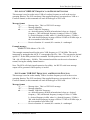
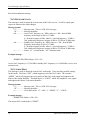
The antenna coax cable should be made of RG-142B or a comparable quality 50Ω coax.
Assembly instructions for the rear coax connector are included in Figure 6.
Apollo SL30 Installation Manual
15
Installation
Clamp Nut
Slit 1/4" (2X)
Step 1.
0.031
- Slide clamp nut over coax.
- Strip coax as illustrated.
- Cut two 1/4" slits in jacket 180
degrees apart.
0.125
0.375
Step 2.
Braid Clamp
- Slide braid clamp over end of coax and
under the braid.
Cap
Step 3.
- Insert coax with braid clamp into
connector and tighten clamp nut securely.
- Solder the center conductor of the coax
to the contact as illustrated.
- Attach the cap and secure tightly.
Solder Center
Conductor
Assembly instructions for right angle connector part #162-1008
Figure 6 - Rear Coax Connector Assembly
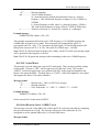
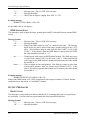
USE OF SPLITTER AND COMBINER
The SL30 is the smallest, most advanced NAV/Comm unit on the market. Its size dictates
room for only one Comm antenna input and one NAV antenna input. It incorporates an
internal diplexor circuit. This means that the input VHF signal must not strip the glideslope
(330 MHz) signal from the NAV (108 MHz) signal. Do not install an external diplexor.
It is recommended that a single VOR/Localizer/Glideslope antenna be used for the
installation. Most VOR/LOC-only antennas will still provide an adequate glideslope signal
for the Apollo SL30 to operate normally. In rare cases, it may be necessary to combine
antenna signals. When the signals are combined, the systems overall performance may be
slightly degraded, but the glideslope signal may increase to an acceptable level.
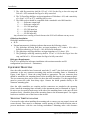
Dual Antennas
If separate VOR and glideslope antennas are used on the aircraft, a splitter/combiner must be
used.
16
VOR/LOC Antenna
1
GS Antenna
2
Splitter/
S
Combiner
SL30 NAV Input
Apollo SL30 Installation Manual
Installation
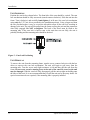
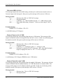
Dual SL30s
If dual SL30s are installed in the aircraft, a splitter must be used.
VOR/LOC/GS Antenna
S
1
Splitter/
Combiner 2
SL30 #1
SL30 #2
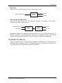
Dual Antennas and Dual SL30s
If dual SL30s and separate VOR and glideslope antennas are installed in the aircraft, a
combiner and a splitter must be used.
VOR/LOC Antenna
GS Antenna
1
Splitter/
S
Combiner
2
S
Splitter/ 1
Combiner
2
SL30 #1
SL30 #2
Installations should use an appropriate splitter/combiner, such as the Mini-Circuits ZFSC-21B BNC, available as an option under the Garmin AT part number 115-0007. This unit has
been fully environmentally qualified for use with single and dual SL30 installations.
EQUIPMENT INTERFACE
Figure 12 through Figure 22 illustrate typical equipment configurations. SL30 installation is
not limited only to equipment shown. The installer must ensure each article interfaced to the
SL30 meets the interface specification listed in this manual.
Apollo SL30 Installation Manual
17
Installation
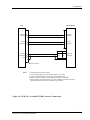
Figure 7 - SL30 Comm Wiring Diagram
18
Apollo SL30 Installation Manual
Installation
Figure 8 - SL30 Comm Typical Audio Panel Connections
Apollo SL30 Installation Manual
19
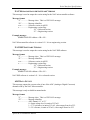
Installation
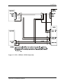
SL30
37-Pin Connector
2 amp fuse
or breaker
Power +
1
+
Ground
2
-
NAV Audio
23
Audio Gnd
20
NAV
Antenna
NOTES: 1.
2.
3.
4.
SL10/15
Audio Panel
Avionics
Power
NAV 1 NAV 2
12
13
1
1
NAV Audio
Audio Gnd
Coax cable to Nav anntena
capable of receiving both
VOR/LOC & GS
Nav Audio may be left floating at the SL30.
Connect shields to designated ground block at the SL10/15.
Avionics power leads should use 20 awg wire. All others are specified at 22-24 awg.
For NAV antenna location, refer to Figure 3, Cable Routing.
Figure 9 - SL30 NAV Power and Audio Connections
Figure 10 – SL30 to Apollo GX50/60 Connections
20
Apollo SL30 Installation Manual
Installation
Figure 11 - SL30 - GX50/60 - MX20 Connections
Apollo SL30 Installation Manual
21
Installation
SL30
Rslvr{H}
Mid Cont MD200-306/307
Rslvr{C}
Rslvr{D}
Rslvr{E}
Rslvr{F}
Rslvr{G}
24
25
7
26
16
34
1
2
3
5
4
6
Rslvr{H}
Rslvr{C}
Rslvr{D}
Rslvr{E}
Rslvr{F}
Rslvr{G}
+NAV Flag
-NAV Flag
+GS Flag
-GS Flag
+TO Flag
+FR Flag
10
29
28
32
12
11
7
8
15
16
9
10
+NAV Flag
-NAV Flag
+Vert (GS) Flag
-Vert (GS) Flag
+TO Flag
+FR Flag
GSI Up
GSI Down
30
31
13 +Up
14 +Down
CDI Left
CDI Right
14
13
11
12
+CDI Left
+CDI Right
17
GPS Ann.
N/C
Back Crse
ILS Enbl
15
33
24
Nav Ann.
18
BC Ann.
19
20
23
22
21
Ann. Pwr - 14V
Ann. Pwr - 28V
14V Dimmer
28V Dimmer *
Ground
To Auto-Pilot
High Sense
37-Pin Connector
* Ground for 14V lighting
+13.8 VDC ** Annunciator
+28 VDC **
Annunciator Power
Backlight Dimmer 14 V Systems
Backlight Dimmer 28 V Systems
**Appropriate Aircraft Bus
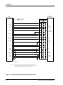
NOTES:
1. Use shieled cable for resolver signals
2. Connect cable shields to the mounting frame: pigtails < 1.25 inches
3. Connect shields chassis ground at both ends of each shielded cable
4. Reference the ACU installation manual if installing NAV/GPS source selector
Figure 12 - SL30 NAV to Mid-Cont MD200-306/307
22
Apollo SL30 Installation Manual
Installation
Mid Cont MD200-302/303
SL30
Rslvr{H}
24
1
Rslvr{H}
Rslvr{C}
Rslvr{D}
Rslvr{E}
Rslvr{F}
25
7
26
16
2
3
5
4
Rslvr{C}
Rslvr{D}
Rslvr{E}
Rslvr{F}
Rslvr{G}
34
6
Rslvr{G}
+NAV Flag
10
7
+NAV Flag
-NAV Flag
29
8
-NAV Flag
+TO Flag
12
9
+TO Flag
+FR Flag
11
10
+FR Flag
CDI Left
CDI Right
14
13
11
12
CDI Left
CDI Right
24
Nav Ann.
Back Crse
ILS Enbl
15
33
18
To Auto-Pilot
High Sense
N/C
+13.8 VDC ** Annunciator
+28 VDC **
Annunciator Power
Backlight Dimmer 14 V Systems
Backlight Dimmer 28 V Systems
37-Pin Connector
BC Ann.
17
GPS
19
20
23
22
21
Ann. Pwr - 14V
Ann. Pwr - 28V
14V Dimmer
28V Dimmer *
Ground
* Ground for 14V lighting
**Appropriate Aircraft Bus
NOTES:
1. Use shieled cable for resolver signals
2. Connect cable shields to the mounting frame: pigtails < 1.25 inches
3. Connect shields chassis ground at both ends of each shielded cable
4. Reference the ACU installation manual if installing NAV/GPS source selector
Figure 13 - SL30 NAV to Mid-Cont MD200-302/303 Connections
Apollo SL30 Installation Manual
23
24
GPS
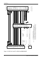
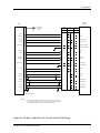
NOTES:
ACU
57 HI Sense
Spare
(Common)
ILS
Energize
Spare
(GPS)
60
62
61
Spare
(Nav)
26
27
CDI Left
33
CDI Right
1. Use shielded cable for Resolver signals
2. Connect cable shields to the mounting frame: pigtails < 1.25 inches
3. Connect shields chassis ground at both ends of each shielded cable
4. Reference the ACU installation manual if installing NAV/GPS source selector
5. ILS and spare annunciator relays are only available in the Mod A ACU.
6. Refer to Limitations on Using a Composite Signal paragraph in this chapter
Required Interconnections
To Auto-Pilot
High Sense
37
Comp Gnd
37-Pin Connector
19
Composite
58
33
ILS Enbl
+13.8 VDC ** Annunciator
+28 VDC **
Annunciator Power
Backlight Dimmer 14 V Systems
Backlight Dimmer 28 V Systems
(GND if 14V)
29
13
To External
Converter
(if used)
28
14
CDI Left
CDI Right
To OBS With
External
Converter
(if used)
Note 6
GSI Down
32
35
14
GSI Up
34
GSI Up 30
GSI Down 31
+FR Flag
16
11
+FR Flag
39
15
41
17
32
12
+TO Flag
-GS Flag
+TO Flag
40
28
+GS Flag
-GS Flag
38
23
29
-NAV Flag
+GS Flag
22
10
+NAV Flag
28V Dimmer *
Ground
Ann. Pwr - 14V
Ann. Pwr - 28V
14V Dimmer
GPS Ann.
NAV Ann.
CDI Right
CDI Left
+DOWN
+FR Flag
+UP
-Vert (GS) Flag
+TO Flag
+Vert (GS) Flag
-NAV Flag
+NAV Flag
BC Ann.
Rslvr{G}
Rslvr{F}
Rslvr{D}
Rslvr{E}
Rslvr{C}
Rslvr{H}
**Appropriate Aircraft Bus
* Ground for 14V lighting
19
20
23
22
21
17
24
12
11
13
14
10
16
9
15
8
7
18
15
Back Crse
21
6
34
20
4
16
Rslvr{F}
Rslvr{G}
-NAV Flag
3
5
7
26
Rslvr{D}
Rslvr{E}
+NAV Flag
2
25
1
24
Rslvr{C}
Mid Cont MD200-306/307
Rslvr{H}
SL30
Installation
Figure 14 - SL30 NAV and ACU to Mid-Cont MD200-306/307
Apollo SL30 Installation Manual
Installation
SL30
STEC IND-351A
Rslvr{H}
24
1
Rslvr{H}
Rslvr{C}
Rslvr{D}
25
7
2
3
Rslvr{C}
Rslvr{D}
Rslvr{E}
26
5
Rslvr{E}
Rslvr{F}
Rslvr{G}
16
34
4
6
Rslvr{F}
Rslvr{G}
+NAV Flag
10
7
+NAV Flag
-NAV Flag
29
8
-NAV Flag
+GS Flag
-GS Flag
28
32
15
16
+GS Flag
-GS Flag
+TO Flag
12
9
+TO Flag
+FR Flag
11
10
+FR Flag
CDI Left
CDI Right
14
13
11
12
CDI Left
CDI Right
GSI Up
30
13
GSI Up
GSI Down
31
14
GSI Down
Back Crse
15
24
BC Ann.
ILS Enbl
33
25
Ann. Dim
23
22
13.8 Dim
27.5 Dim
21
Ground
To Auto-Pilot
High Sense
37-Pin Connector
Backlight Dimmer
28 V Systems
(GND if 14V)
Backlight Dimmer
14 V Systems
BC Annunciator
Dimmer 12V max
NOTES:
1. Use shieled cable for Resolver signals
2. Connect cable shields to the mounting frame: pigtails < 1.25 inches
3. Connect shields chassis ground at both ends of each shielded cable
4. Reference the ACU installation manual if installing NAV/GPS source selector.
5. Installer should verify that the STEC IND-351A contains the proper
annunciator, i.e., BC backcourse.
Figure 15 - SL30 NAV to STEC IND-351A Connections
Apollo SL30 Installation Manual
25
Installation
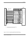
Bendix King
Nav Converter
SL30
Bendix/King
KN 72
Bendix/King Bendix/King
KN 203
KN 204
Bendix/King Bendix/King
KN 208
KN 208A
Bendix/King Bendix/King
KN 209
KN 209A
GSI Up
30
k
3
29
Glideslope Deviation +Up
GSI Down
31
m
6
28
Glideslope Deviation +Down
+GS Flag
28
H
9
25
Glideslope Deviation +Flag
-GS Flag
32
J
12
24
Glideslope Deviation -Flag
ILS Enbl
33
S
8
K
4
10
4
10
ILS Energize
Composite
19
6
Y
Y
2
6
2
6
VOR/LOC Composite In
37-Pin Connector
NOTES: 1. Connect shield grounds to aircraft chassis with as short a conductor as practical.
2. Refer to Limitations on Using Composite Signal paragraph in this chapter.
3. Not all indicator connections are shown, only those interfacing to the SL30. Consult the
appropriate installation manuals for complete wiring instructions.
Figure 16 - SL30 NAV to Bendix/King KN72/203/204/208/208A/209/209A Wiring
26
Apollo SL30 Installation Manual
Installation
Bendix King
Indicators
SL30
Back Course 15
GSI Up
30
GSI Down
31
+GS Flag
28
Amber
BC
Light
Lamp Voltage
From Dimmer
Circuit
Bendix/King
KI 202
Bendix/King
KI 206
Bendix/King
KI 207
P2021
P2061
P2071
k
Bendix/King Bendix/King
KI 525A
KPI 552
P1
P2
P101
k
E
JJ
Glideslope Deviation +Up
m
m
B
H
H
Glideslope Deviation +Down
H
H
J
FF
Glideslope Deviation +Flag
W
G
G
Glideslope Deviation -Flag
-GS Flag
32
CDI Right
13
j
j
j
b
h
Course Deviation + Right
CDI Left
14
n
n
n
V
i
Course Deviation + Left
NAV Flag + 10
N
N
N
K
f
NAV Flag +
NAV Flag -
29
F
F
F
F
g
NAV Flag -
+ From
11
S
S
S
T
k
+ From
+ To
12
e
e
e
Z
j
+ To
Rslvr{H}
24
c
c
X
W
OBS Resolver H
Rslvr{C}
25
Z
Z
a
V
OBS Resolver C
OBS Resolver D
J
J
Rslvr{D}
7
L
L
V
Z
Rslvr{E}
26
P
P
Y
a
Rslvr{F}
16
T
T
b
Y
Rslvr{G}
34
W
W
e
X
OBS Resolver E
OBS Resolver F
OBS Resolver G
37-Pin Connector
NOTES:
1. Connect shield grounds to aircraft chassis with as short a conductor as practical.
2. Not all indicator connections are shown, only those interfacing to the SL30. Consult
the appropriate installation manuals for complete wiring instructions.
Figure 17 - SL30 NAV to Bendix/King KI202/206/525A/KPI552 Wiring
Apollo SL30 Installation Manual
27
Installation
Sandel SN3308
SL30
Rslvr{H}
Rslvr{C}
Rslvr{D}
24
25
7
Rslvr{E}
Rslvr{F}
Rslvr{G}
26
16
34
+NAV Flag
-NAV Flag
+GS Flag
10
29
28
18
36
15
+NAV Flag
-NAV Flag
+GS Flag
-GS Flag
+TO Flag
+FR Flag
32
12
11
33
17
35
-GS Flag
+TO Flag
+FR Flag
GSI Up
30
31
16
34
GSI Up
GSI Down
CDI Left
14
37
CDI Left
CDI Right
13
19
CDI Right
Back Crse
ILS Enbl
15
33
Amber
BC
Light
13
OBS In
32
COS
28
14
VREF
SIN
GSI Down
Lamp Voltage
From Dimmer
Circuit.
Note 5
37-Pin Connector
NOTES:
1. Use shieled cable for resolver signals.
2. Connect cable shields to the mounting frame: pigtails < 1.25 inches.
3. Connect shields chassis ground at both ends of each shielded cable.
4. Reference Sandel installation manual for switching NAV signals with GPS.
5. BC annunciator may be implemented in future software revisions of the SN3308.
Refer to Sandel installation manual.
6. Not all indicator connections are shown, only those interfacing to the SL30. Consult the
appropriate installation manuals for complete wiring instructions.
Figure 18 - SL30 NAV to Sandel Discrete Connections
28
Apollo SL30 Installation Manual
Installation
SL30
Sandel SN3308
+GS Flag
28
15
+GS Flag
-GS Flag
32
33
-GS Flag
GSI Up
30
31
16
34
GSI Up
GSI Down
ILS Enbl
33
NAV 1
27
Composite 19
29
GSI Down
NAV 2
8
ILS Enrgze
10
Composite
Gnd 37
37-Pin Connector
NOTES:
1. Use shieled cable for resolver signals.
2. Connect cable shields to the mounting frame: pigtails < 1.25 inches.
3. Connect shields chassis ground at both ends of each shielded cable.
4. Refer to Limitations on Using a Composite Signal paragraph in this chapter.
5. Not all indicator connections are shown, only those interfacing to the SL30. Consult the
appropriate installation manuals for complete wiring instructions.
Figure 19 - SL30 NAV to Sandel SN3308 Converter Connections
Apollo SL30 Installation Manual
29
Installation
Sperry
Unisys/Honeywell
SL30
Back Course 15
Amber
BC
Light
Lamp Voltage
From Dimmer
Circuit
Sperry
RD 550A
P1
P2
Sperry
RD 650
P1
P2
GSI Up
30
C
5
+Up
GSI Down
31
D
6
+Down
+GS Flag
28
Glideslope +Flag
-GS Flag
32
Glideslope -Flag
GS Superflag
9
U
Glideslope Superflag
38
W
8
Glideslope Superflag Lo
CDI Right
13
E
3
+ Right
CDI Left
14
F
4
+ Left
NAV Flag +
10
NAV Flag +
NAV Flag -
29
NAV Flag -
NAV Superflag
27
P
39
NAV Superflag
S
36
NAV Superflag Lo
+ From
11
A
1
+ From
+ To
12
B
2
+ To
Rslvr{H}
24
DD
6
OBS A/H
Rslvr{C}
25
FF
8
OBS C
Rslvr{D}
7
z
9
OBS D (COS Hi)
Rslvr{E}
26
AA
10
OBS E (COS Lo)
Rslvr{F}
16
BB
11
OBS F (SIN Lo)
Rslvr{G}
34
CC
12
OBS G (SIN Lo)
37-Pin Connector
NOTES:
1. Connect shield grounds to aircraft chassis with as short a conductor as practical.
2. Not all indicator connections are shown, only those interfacing to the SL30. Consult
the appropriate installation manuals for complete wiring instructions.
Figure 20 - SL30 to Sperry RD 550A and RD650 Wiring
30
Apollo SL30 Installation Manual
Installation
Collins
Rockwell
SL30
Back Course 15
Amber
BC
Light
Lamp Voltage
From Dimmer
Circuit
Collins
331A-6P
P1
Collins
331A-9G
P1
P2
Collins
PN-101
P1
GSI Up
30
33
5
r
+Up
GSI Down
31
34
6
q
+Down
+GS Flag
28
35
s
Glideslope +Flag
-GS Flag
32
36
t
Glideslope -Flag
GS Superflag
9
Glideslope Superflag
7
Glideslope Superflag Lo
CDI Right
13
28
3
i
+ Right
CDI Left
14
29
4
j
+ Left
NAV Flag +
10
31
k
NAV Flag +
NAV Flag -
29
32
m
NAV Flag -
NAV Superflag
27
+ From
11
26
37
NAV Superflag
38
NAV Superflag Lo
1
p
+ From
2
n
+ To
+ To
12
27
Rslvr{H}
24
1
1
h
OBS A/H
Rslvr{C}
25
3
3
c
OBS C
Rslvr{D}
7
4
4
d
OBS D (COS Hi)
Rslvr{E}
26
5
5
e
OBS E (COS Lo)
Rslvr{F}
16
6
6
f
OBS F (SIN Lo)
Rslvr{G}
34
7
7
g
OBS G (SIN Lo)
37-Pin Connector
NOTES:
1. Connect shield grounds to aircraft chassis with as short a conductor as practical.
2. Not all indicator connections are shown, only those interfacing to the SL30. Consult
the appropriate installation manuals for complete wiring instructions.
Figure 21 - SL30 to Collins 331A-6P, 331A-9G, and PN-101 Wiring
Apollo SL30 Installation Manual
31
Installation
Century Flight
Systems
SL30
Back Course 15
Amber
BC
Light
Lamp Voltage
From Dimmer
Circuit
Century
NSD 360A
Century
NSD 1000
CD 132
CD 132
GSI Up
30
27
27
Glideslope +Up
GSI Down
31
28
28
Glideslope +Down
+GS Flag
28
30
30
Glideslope Flag +
-GS Flag
32
29
29
Glideslope Flag -
CDI Right
13
18
18
Right Dev +
CDI Left
14
17
17
Left Dev +
NAV Flag + 10
31
31
NAV Flag +
NAV Flag -
29
32
32
NAV Flag -
+ From
11
34
34
From +
+ To
12
33
33
To +
Rslvr{H}
24
15
15
OBS Rotor H
Rslvr{C}
25
16
16
OBS Rotor C
Rslvr{D}
7
24
24
OBS Stator D
Rslvr{E}
26
23
23
Rslvr{F}
16
26
26
Rslvr{G}
34
25
25
OBS Stator E
OBS Stator F
OBS Stator G
37-Pin Connector
NOTES:
1. Connect shield grounds to aircraft chassis with as short a conductor as practical.
2. Not all indicator connections are shown, only those interfacing to the SL30. Consult
the appropriate installation manuals for complete wiring instructions.
Figure 22 - SL30 to Century NSD 360A and NSD 1000 Wiring
32
Apollo SL30 Installation Manual
Installation
LIMITATIONS ON USING A COMPOSITE SIGNAL
If an external converter is driven from the composite output in conjunction with a full
function CDI/HSI with resolver, the indicator head type, when selected from the Setup Mode
during the post installation checkout, should be RESOLVER. In this installation, the composite
output will be disabled whenever the VOR monitor mode is active or back course localizer
mode is enabled. This will cause the external converter to flag. If the CONVERTER option is
selected from the Setup Mode as the indicator head type, neither of these two options is
available to the pilot and the composite output should always be valid. The CONVERTER setup
option should be used if an external converter is the only indicator interfaced to the SL30.
LIMITATIONS ON DISTANCE, SPEED, AND TIME INFORMATION
When Nav tuning is provided to the Apollo GX, the GX will output Distance, Speed, and
Time (DST) information on the MapCom output. It is the installer’s responsibility to ensure
that this information is displayed in an acceptable fashion. For instance, in an installation
where two Apollo SL30’s are integrated in the system, it is not appropriate to display DST
information on the SL30 that is not providing the tuning information. Apollo SL30 SW
version 1.2, or later, provides the means for disabling the display of DST information.
POST INSTALLATION CHECKOUT
Once the unit is installed, complete the checkout procedure to verify proper operation. Refer
to the User’s Guide for operating instructions.
The steps that are not applicable to a particular installation may be skipped. A checkout log
sheet is included on page 39 to fill out during the checkout procedure. Make a photocopy of
the log sheet for ease of use if desired.
MOUNTING / WIRING CHECK
Verify that all cables are properly secured and shields are connected to the rear of the
mounting frame. Check the movement of the aircraft controls to verify that there is no
interference.
SETUP AND CHECKOUT
The SL30 has a built-in I/O test mode to simplify system setup and checkout. To operate the
SL30 in the Setup Mode, hold down the Ù and SYS buttons while switching on the power.
You must continue to hold the buttons in until a complete power up is done and SELECT CDI
is displayed. To return to normal operation, switch the power off, and then back on.
In the Setup Mode, turn the large knob to view each function. In general, press the SEL
button to activate selection, turn the small knob to view each option, and then press ENT to
save the displayed value. Pressing SEL again will exit the option without saving any changes.
NAV Setup and Checkout
Apollo SL30 Installation Manual
33
Installation
Indicator Head Type
Set up the SL30 for the indicator head type that it is connected to by using the Setup Mode as
follows.
1. Rotate the large knob to the SELECT INDICATOR HEAD TYPE display.
2. Press SEL. The type will flash.
3. Turn the small knob to select desired option: NONE, RESOLVER, CONVERTER, or SERIAL.
Selecting the RESOLVER option requires calibration, which is available by turning the
large knob CW to the next display. The options are defined as follows:
• NONE: No external resolver is supported. OBS mode allows the user to edit the OBS
with concentric knobs. Serial OBS update messages are supported in this mode, but
the unit will not flag if updates are discontinued or are not periodic.
• RESOLVER: Auto-decodes resolver setting via six-wire resolver interface. Uses
internal DSP to compute course information.
• CONVERTER: Disables all internal OBS functions. Disables VOR monitor and BC
selection. It allows use of conventional external converter via the composite output
pin.
• SERIAL: For use with serial Electronic Flight Instruments (EFIS) conforming to
Garmin AT SL30 serial data specification. See Appendix E – Serial Interface
Specifications. If serial OBS data is not received at a minimum 1 Hz rate, the NAV
unit will flag.
Note: No serial test messages are sent in the Setup Mode while testing CDI and GSI
flags.
4. Press ENT to accept and save the selected option.
Calibrating the Resolver Indicator Head Type
After selecting RESOLVER as the indicator head, it is necessary to calibrate the interface
between the SL30 and the resolver. The SL30 cannot drive multiple resolvers at the same
time. It is not recommended that external resolvers be switched through a relay or other
means because the resolver must be calibrated to the radio as described in this procedure. If
multiple resolvers are desired in the installation, the primary unit must be installed and
calibrated as described here. The secondary unit should use the composite output.
1. After selecting RESOLVER as the indicator head type, turn the large knob to the PRESS
SEL TO CALIBRATE RESOLVER display.
2. Press SEL.
3. Follow the directions on the SL30 display.
Note: The accuracy of the system is dependent on this calibration. Do not rush this step.
4. At the end of the setup, press ENT to store the results.
5. Cycle the power switch (enter the normal mode).
6. Tune a VOR station (any VOR frequency).
7. Press OBS button.
8. Verify that the OBS decodes properly from 0 to 360 degrees.
If the SL0 will not accept the calibration or advances to the next prompt when the ENT key is
pressed, there may be a problem with the resolver interface.
34
Apollo SL30 Installation Manual
Installation
Control Test
In the Setup Mode, turn the large knob to reach the CONTROL TEST page. This function tests
the operation of the front panel controls on the SL30.
1. Press each button. The function name for each control will appear on the display after the
button is pressed.
2. Turn the small knob. The numeric values on the right side of the display will change.
Display Test
In the Setup Mode, turn the large knob to reach the PRESS SEL TO TEST DISPLAY page.
1. Press SEL.
2. A series of display tests will be performed to test each LED. Observe the display for any
missing LEDs.
3. When the test is completed, the display will return to normal mode.
Flags Test
The Flags test in Setup Mode sends an active signal for each selected flag so you can test the
interface to the connected devices directly from the front panel while you are on the ground.
The Flag tests include LOC (Localizer), BC (Back Course), FR (From), TO (TO), NAV
(NAV), and GS (Glideslope). When a selection is in large text, an active signal is sent from
the SL30.
1. In the Setup Mode, turn the large knob to the FLAGS TEST page.
2. Press SEL. The Localizer (LOC) selection will flash.
3. Turn the small knob to change the selection to large text. Check the attached indicator for
the appropriate flag. Turn the small knob one click in either direction to change the
selection back to small text.
4. Turn the large knob to the next flag type and turn the small knob to change it to large
text. You can only select FR or TO as active, not both at the same time.
5. Ensure the flags are reset to all small text when you are finished testing.
CDI Test
This function tests for CDI function and allows for calibration between the SL30 and the
attached CDI.
1. In the Setup Mode, turn the large knob to reach the CDI TEST page.
2. Press SEL to activate selection. The value will flash.
3. Rotate the small knob to change the value. The values "0-6" may be used to center the
CDI needle.
4. Turn the small knob left or right to center the needle.
5. Press ENT when the needle is centered.
6. Turning the small knob left or right past a value of "6" will test the deflection of the CDI
needle.
GSI Test
This function tests for GSI function and allows for calibration between the SL30 and the
attached GSI.
1. In the Setup Mode, turn the large knob to reach the GSI TEST page.
2. Press SEL to activate selection. The value will flash.
Apollo SL30 Installation Manual
35
Installation
3. Rotate the small knob to change the value. The values "0-6" may be used to center the
GSI needle.
4. Turn the small knob left or right to center the needle.
5. Press ENT when the needle is centered.
6. Turning the small knob left or right past a value of "6" will test the deflection of the GSI
needle.
DST Disable
The installer may need to disable the DST function when the unit is the second unit of a dual
installation.
1. In the Setup Mode, turn the large knob to the ENABLE DST DATA DISPLAY page.
2. Press SEL. The selection will flash.
3. Turn the small knob to choose Yes or No.
4. Press ENT after making your selection.
VHF NAV Checkout
On the Ground
Check the VOR reception with ground equipment, operating VOT or VOR, and verify audio
and Morse code ID functions (if possible). Tune a Localizer frequency and verify the CDI
needle and NAV flag, and GSI needle GS flag.
Some VOR test equipment may not be compatible with the digital signal processing of the
Apollo SL30 and will give erroneous results. Examples of equipment known to function
properly are: IFR Nav 750 and Collins 479S-6.
Comm Setup and Checkout
Com RF Squelch
This valued is used by the Comm function to control its squelch level. It is usually not
necessary to adjust this value from its factory setting.
1. In the Setup Mode, turn the large knob to reach the COM RF SQUELCH page.
2. Press SEL to activate selection. The value will flash.
3. Rotate the small knob to change the level number. The range of the number is 25 to 100.
Note: The larger the number the stronger the signal must be in order for the radio to
break squelch. The factory default value is 56.
4. Press ENT to save the value and exit the Setup Mode.
Microphone 1 and 2 Gain
Set the microphone gain for microphones 1 and 2 for values from 0 to 255.
1. In the Setup Mode, rotate the large knob to select MICROPHONE 1 (or 2) GAIN.
2. Press SEL to activate selection. The Mic 1 value will flash.
3. Turn the small knob to change the value.
4. Turn the large knob to the Mic 2 value. Turn the small knob to change the value.
5. Press ENT to accept and save the settings.
Note: A value of 128 will work well for most headset units.
36
Apollo SL30 Installation Manual
Installation
Enable weather frequencies
This function determines whether the weather frequencies in common use in North America
are displayed, or not.
1. In the Setup Mode, rotate the large knob to select ENABLE WEATHER FREQUENCIES.
2. Press SEL to activate selection. The Yes or No value will flash.
3. Turn the small knob to change the value.
4. Press ENT to accept and save the settings.
VHF Comm Checkout
Receiver / Transmitter Operation
Tune the unit to a local frequency and verify the receiver output produces a clear and
understandable audio output. Verify the transmitter functions properly by contacting another
station and getting a report of reliable communications. Check the remote flip/flop.
Antenna Check
The antenna Vswr can be checked using an inline wattmeter in the antenna coax using
frequencies near both ends of the band. The Vswr should be < 2:1, and is not to exceed 3:1. A
Vswr of 2:1 will cause a drop in output power of approximately 12%, and 3:1 causes
approximately a 26% drop.
Sidetone Level Adjustment
The sidetone volume was preset at the factory to a typical audio level. The level can be
adjusted using one of the built-in system functions. To adjust the sidetone level:
1. Press SYS, rotate the large knob to the COM RADIO INFO: page, and press ENT.
2. Rotate the large knob to the SIDETONE LEVEL: page.
3. Rotate the small knob to adjust the sidetone level. The sidetone level is displayed in a
range of 1 to 100, and variable. The sidetone level can be adjusted during transmit.
Transmit Mic Selection
The Transmit Microphone page controls which microphone is permitted to transmit. Choose
Mic 1, 2, or both. To select the Transmit Mic control:
1. Press the SYS button and rotate the large knob to TRANSMIT MIC page.
2. Rotate the small knob to select MIC1, MIC2, or MIC1+MIC2.
3. Select an appropriate frequency, key the transmitter, and talk into the microphones to
check for the intended operation.
FINAL SYSTEM CHECK
The SL30 functions should be complete at this time. The final check includes verifying VOR
and ILS operation. Start with the unit turned on and operating in the normal mode. Refer to
the user’s manual for operating instructions.
RS-232 Serial Interface Checks
The interfaces to other equipment, such as the GX series GPS, should be checked as follows:
1. Operate the SL30 and GX unit in normal mode.
2. Press the Direct To button on the GPS unit and select an airport. Press ENT.
3. Operate the SL30 in Comm mode. Press SEL.
Apollo SL30 Installation Manual
37
Installation
4. Verify that the remote frequencies of the airport selected via the GPS unit are displayed
on the SL30.
The interface to a DST data source (such as an Apollo GX or DB30) should be checked as
follows:
1. Operate the SL30 in NAV mode and ensure the DME is operating with a valid signal.
2. Press the SEL button to bring up the NAV frequency recall lists.
3. Turn the large knob one click to the left (counterclockwise) to show the DST display
prompt. If you do not see the Show DST Display, either the feature is disabled, or you are
not receiving the data through the serial port.
4. Press ENT to replace the current NAV display with DST data. Verify that DST data is
passed to the SL30.
To check the serial data output connections, verify the data from the SL30 can be displayed
on the other units, such as the MX series multi-function display or the Apollo GX Nav
Frequency display. For serial interface checks to a serial CDI consult the CDI installation
checkout procedures.
Comm Flight Test Check
A flight test is recommended as a final installation verification. The performance may be
verified by contacting a ground station at a range of at least 50nm while maintaining an
appropriate altitude and over all normal flight attitudes. Performance should be checked using
low, high, and mid band frequencies.
Check the VOR
1. Tune a local VOR station within 50 miles.
2. Verify the audio ident/voice quality.
3. Verify the Morse code decoder IDs the station (95% probability).
4. Fly to and from the station.
5. Verify NAV flag, TO/FR flag, and CDI are operational.
6. Record accuracy in System Log (see manual).
Check the ILS
1. Tune an ILS at the local airport.
2. Verify the audio ident/voice quality.
3. Verify the Morse code decoder IDs the station (95% probability).
4. Fly the approach.
5. Verify NAV flag, GS flag, and CDI and GSI are operational.
6. Verify BC annunciator.
38
Apollo SL30 Installation Manual
Installation
APOLLO SL30 POST-INSTALLATION CHECKOUT LOG
Date: ___/___/___
By: _____________
CONFIGURATION INFORMATION:
SL30 NAV/COMM 430-6040-3_____ Mod ____ Serial # ___________
TEST MODE CHECKOUT AND SETUP:
Avionics Outputs:
[ ] Resolver
[ ] Converter
[ ] Serial
[ ] Calibration (if Resolver)
[ ] Control Test
[ ] Display Test
[ ] NAV Valid flag
[ ] GS Valid flag
[ ] TO/FROM flag (OFF, TO, FROM)
[ ] External annunciator (BC)
[ ] CDI (left, mid, right)
[ ] GS (up, mid, down)
[ ] Enable Weather Freq Yes ___ No___
[
VHF NAV CHECKOUT:
VOR reception with ground equipment
[ ] Audio and Morse code ID functions
[ ] Verify CDI NAV and GSI GS flags
VHF COMM CHECKOUT:
[ ] Receiver / Transmitter operation
[
[ ] Antenna check
[
[ ] Remote flip/flop input
FINAL SYSTEM CHECK:
[ ] RS-232 inputs/outputs checked (Optional)
[ ] Comm Operation
[ ] VOR Check
[ ] Station ID
[ ] TO/FR
[
[ ] Left/Right (CDI)
[ ] Valid Flag (NAV)
[ ] Radial (To/From)
______Bearing Error
[ ] Remote Flip/Flop input
COMMENTS:
Apollo SL30 Installation Manual
[ ] None
] Enable DST Display Yes ___ No___
] Sidetone level set / checked
] Transmit Mic selection
] ILS Check
[ ] Station ID
[ ] Valid Flags (NAV/GS)
[ ] Left/Right (CDI)
[ ] Up/Down (GSI)
[ ] BC Function (Annunciator)
39
Installation
INSTRUCTIONS FOR CONTINUED AIRWORTHINESS
Modification of an aircraft for the installation of the SL30 obligates the aircraft operator to
include the maintenance information provided by this section in the operator’s Aircraft
Maintenance Manual and the operator’s Aircraft Scheduled Maintenance Program.
1. Maintenance manual information (system description, operation, location, removal,
testing, etc.) is contained within this document and any information should be copied to,
and/or included with, the operator’s airplane Maintenance Manual.
2. Line Replaceable Unit (LRU) part numbers and other necessary part numbers contained
in the installation data package should be placed into the aircraft operator’s airplane
Illustrated Parts Catalog (IPC).
3. The specific wiring diagram information, along with the supplemental information
described in the Installation Manual, pertaining to the installation of this unit, should be
placed into the aircraft operator’s airplane Wiring Diagram Manuals.
4. Scheduled Maintenance Program tasks to be added to the operator’s maintenance
program are found in Appendix B – Periodic Maintenance, of this installation manual.
40
Apollo SL30 Installation Manual
Specifications
SECTION 3 - SPECIFICATIONS
This section includes detailed electrical, physical, environmental and performance
specifications for the Apollo SL30.
Note: Performance specifications are measured at ambient temperatures unless otherwise
noted.
ELECTRICAL
Input voltage............................................. 10 VDC to 36 VDC, reverse polarity protected
Input current (VHF navigation input) ...... 325 mA typical, 500 mA max at 13.75 VDC
170 mA typical, 350 mA max at 27.5 VDC
Input current (Comm input) ..................... 270 mA typical, 2 A max at 13.75 VDC, receive
130 mA typical, 900 mA max at 27.5 VDC, receive
2.1 A typical, 3.2 A max at 13.75 VDC, transmit
1.0 A typical, 1.4 A max at 27.5 VDC, transmit
Note: receive max at full receive audio, transmit
max at 90% modulation at 1000 Hz.
Input power (Comm input)....................... 3.7 watts typical, receive
28 watts typical, transmit
Internal fuses ............................................ Nav input: 3 amp fast blow, socketed on board
Comm input : 7 amp fast blow, soldered in board
Memory backup........................................ Internal flash memory
PHYSICAL
Height ....................................................... 1.30 inches (3.30 cm)
Width ........................................................ 6.25 inches (15.88 cm)
Depth ........................................................ 11.452 inches (29.09 cm) behind panel, including
mounting frame and connectors
Weight (without mounting frame)............ 2.25 lb. (1.02 kg)
ENVIRONMENTAL
The Apollo SL30 is designed and tested to meet appropriate categories of RTCA/DO-160C
and RTCA/DO-160D. The Environmental Qualification Form is included in Appendix C.
Operating temperature.............................. -20°C to +55°C
Storage temperature.................................. -55°C to +85°C
Temperature variation .............................. 2°C per minute
Humidity................................................... 95% at 65°C for 48 hours
Maximum altitude .................................... 25,000 feet
Cooling ..................................................... Not required
Apollo SL30 Installation Manual
41
Specifications
Figure 23 - Unit Dimensions
AVIONICS OUTPUTS
CDI L/R deviation ....................................±150 mV full scale, will drive up to 200-ohm load
TO/OFF/FROM flag .................................±250 mV, TO/FROM indication, will drive up to
200-ohm load
Nav valid flag............................................+300 mV for valid indication, will drive up to 200ohm load
Nav superflag ............................................Vin - 2 volts minimum for valid, source capability
of 400 mA
GSI U/D deviation ....................................±150 mV full scale, will drive up to 200-ohm load
GS valid flag .............................................+300 mV for valid indication, will drive up to 200ohm load
GS superflag..............................................Vin - 2 volts minimum for valid, source capability
of 400 mA
Annunciators .............................................Open collector outputs capable of sinking up to
400 mA for turning on annunciator lamps
• BC
• Localizer
Power Control ...........................................Open collector output capable of sinking up to
50 mA. Active when unit is powered up.
42
Apollo SL30 Installation Manual
Specifications
NAV RECEIVER PERFORMANCE
VOR
TSO/JTSO compliance............................. TSO-C40c (DO-196)/JTSO 2C40c
Applicable documents .............................. RTCA DO-196
Operational class ...................................... N/A
Accuracy category.................................... B {-46oC to + 55o C }
Frequency range ....................................... 108.00 to 117.95 MHz in 50 kHz increments
Frequency tolerance ................................. 0.0008%
Cross modulation products....................... At least 60 dB down
Receiver sensitivity .................................. 108 MHz –115 dBm typical
117 MHz –117 dBm typical
Course accuracy ....................................... RTCA DO-196 two sigma limit: 3o
SL30 performance: less than 0.5o typical
Audio output............................................. With a 1 kHz tone 30% modulation at least 100 mW
output into 500 ohm loads
Ident/voice................................................ With 100 mV input, 30% modulation at 1020 Hz,
the ident/voice tone ratio shall not be less than15
dB
Audio response......................................... Less than 6 dB variation from 350 Hz to 2500 Hz
LOCALIZER
TSO compliance ....................................... TSO-C36e (DO-195)/JTSO C36e
Applicable documents .............................. RTCA DO-195
Operational class ...................................... A {manual landing systems}
Accuracy category.................................... B {-46oC to + 55oC }
Frequency range ....................................... 108.00 to 111.95 MHz
Frequency tolerance ................................. 0.0008%
Cross modulation products....................... At least 60 dB down
Receiver sensitivity .................................. -115 dBm typical
Centering error ......................................... RTCA DO-195 two sigma limit: 6.6% of full scale
SL30 performance: less than 1.0% typical (1.5 mV)
Audio output............................................. With a 1 kHz tone 30% modulation at least 100 mW
output into 500 ohm loads
Ident/voice................................................ With 100 mV input, 30% modulation at 1020 Hz,
the ident/voice tone ratio shall not be less than15
dB
Apollo SL30 Installation Manual
43
Specifications
Audio response .........................................Less than 6 dB variation from 350 Hz to 2500 Hz
GLIDESLOPE
TSO compliance........................................TSO-C34e (DO-192)/JTSO C34e
Applicable documents...............................RTCA DO-192
Operational class.......................................N/A
Accuracy category ....................................B {-46oC to + 55oC }
Frequency range........................................329.150 to 335.00 MHz
Frequency tolerance ..................................0.0008%
Cross modulation products .......................At least 60 dB down
Receiver sensitivity...................................-95 dBm typical
Centering error ..........................................RTCA DO-195 two sigma limit: 6.7% of full scale
SL30 performance: less than 2.0% typical (3.0 mV)
OBS RESOLVER
TSO compliance........................................TSO-C40c (DO-196)/JTSO 2C40c
Applicable documents...............................RTCA DO-196
Operational class.......................................N/A
Accuracy category ....................................B {-46oC to + 55oC}
Output signal.............................................300 Hz ± 2 Hz (rounded square wave)
Output voltage (automatically
adjusted during calibration) ...............5 Vpp to 10 Vpp
Input voltage max (calibrated)..................5 Vpp (when OBS is set to maximum)
Resolver voltage gain (loss)......................1:1 maximum, 2:1 minimum
Output loading at max voltage..................100 ohms impedance
Accuracy/Resolution.................................0.25o rounded to 1o steps
COMPOSITE OUTPUT
VOR Mode
Band pass frequency .................................0 Hz to 15 kHz
Variation over frequency range ................Less than 2 dB
Output signal voltage ................................0.500 VRMS
Output loading ..........................................1,000 ohms (max)
LOC Mode
Band pass frequency .................................0 Hz to 15 kHz
Variation over frequency range ................Less than 2 dB
44
Apollo SL30 Installation Manual
Specifications
Output signal voltage ............................... 0.390 VRMS (0.275 VRMS @ 90 Hz, 0.275 VRMS @
150 Hz)
Output loading.......................................... 1,000 ohms (max)
ILS energize signal................................... Sinks up to 400 mA (max)
COMM RECEIVER PERFORMANCE
Class ......................................................... D
Frequency range ....................................... 118.000 to 136.975 MHz, 760 channels
Sensitivity................................................. 1 µV (2 µV hard) for 6 dB S+N/N with 30%
modulation at 1000 Hz
Selectivity................................................. < 6dB variation at ± 7 kHz, > 60 dB at ± 22 kHz
Speaker audio output level ....................... 12 watts into 4 Ω, 8 watts into 8 Ω
Headphone audio output level.................. 280 mW into 100 Ω, 120 mW into 500 Ω
Distortion.................................................. < 5% at rated output at 1000 Hz
AGC characteristics.................................. < 3db variation in audio output from 5 µV to 100
mV input, 15% to 90% modulation
Squelch control......................................... Automatic squelch with manual override
COMM TRANSMITTER PERFORMANCE
Class ......................................................... 4
Output power............................................ 8 watts minimum carrier at >12 VDC input,
6 watts minimum at 10 VDC input
(transmit is locked out below 9 volts input)
Frequency range ....................................... 118.000 to 136.975 MHz, 760 channels
Frequency tolerance ................................. ±15 ppm from -20°C to +70°C
Microphone input ..................................... Two inputs, standard carbon or dynamic mic with
integrated preamp providing minimum 70 mv rms
into 1000 Ω load
Modulation capability .............................. 85% with 100 mv to 1000 mv rms microphone
input at 1000 Hz
Audio frequency distortion....................... < 10% at 85% modulation at 350 to 2500 Hz
Audio frequency response........................ < 4 dB variation with 350 to 2500 Hz, 85%
modulation
Carrier noise level .................................... > 35 dB down
Sidetone output......................................... up to 280 mW into 100 Ω, 120 mW into 500 Ω
Duty cycle ................................................ 100%
Apollo SL30 Installation Manual
45
Specifications
Stuck mic time-out....................................35-second time-out, reverts to receive
INTERCOM PERFORMANCE
Microphone input......................................Two inputs, standard carbon or dynamic mic with
integrated preamp providing minimum 70 mv rms
into 1000 Ω load
Headphone audio output level ..................280 mW into 100 Ω, 120 mW into 500 Ω
AGC characteristics ..................................output varies < 3 dB with input of 100 mv rms to
1000 mv rms
CONTROL INPUTS
Transmit key .............................................Input pulled low to ground to enable the transmitter
Intercom select ..........................................Input pulled low to ground to enable the intercom
function
Flip/Flop....................................................Remote Comm flip/flop input, connect to a
momentary button to ground for remote flip/flop
operation.
ANTENNA REQUIREMENTS
COMM ANTENNA
The Apollo SL30 requires a VHF Comm antenna meeting the following specifications:
•
Standard 50 Ω vertically polarized antenna with a VSWR < 2.5:1.
NAV ANTENNA
The Apollo SL30 requires a VHF NAV antenna meeting the following specifications:
• Standard 50 Ω horizontally polarized antenna with a VSWR < 3:1
• Capable of receiving VOR/LOC/GS (Recommend Comant Industries P/N CI 157P)
• 108.00 – 117.95 MHz (VOR/LOC)
• 328.60 – 335.4 MHz (GS)
Note: Multiple NAV antennas may be used with an RF signal splitter/combiner, part number
115-0007, at the radio. Refer to page 16.
46
Apollo SL30 Installation Manual
Specifications
SERIAL INTERFACE
RS-232...................................................... Defined in Appendix E - Serial Interface
Specifications
REAR CONNECTOR PINOUT
The SL30 includes two rear panel connectors, a 15-pin for the Comm interface connections
and a 37-pin for the rear panel connections. The pinout for the connectors is listed in the
following tables.
Table 2 - Comm Interface Connector Pinout
Pin #
I/O
Connection
Function
1
2
3
4
5
6
7
8
9
10
11
12
I
I
O
I
-O
I
I
I
I
O
I
Power +
Reserved
Reserved
TxKey
NC
Speaker
Mic ground
Mic 1
Power ground
Reserved
Reserved
Intercom select
13
14
15
O
O
I
Audio ground
Headphone
Mic 2
Main DC power input
Do not connect
Do not connect
Transmit enable key, pulled low to transmit
Do not connect
Speaker terminal output
Microphone input ground connection
Microphone input #1
Main power ground input
Do not connect
Do not connect
Intercom function select, pulled low to turn on the intercom
function
Speaker and headphone ground connection
Headphone terminal output
Microphone input #2
1
8
9
15
Viewed from rear of unit
Apollo SL30 Installation Manual
47
Specifications
Table 3 - Rear Panel Connector Pinout
Pin #
I/O
1
2
3
4
5
6
7
8
9
10
11
12
13
14
15
16
17
18
19
20
21
22
23
24
25
26
27
28
29
30
31
32
33
34
35
36
37
I
I
O
I
O
I
I
I
O
O
O
O
O
O
O
O
--O
O
O
O
O
O
O
I
O
O
O
O
O
O
O
O
-O
O
Connection
Function
Power +
Power ground
Serial ground
RxD1
TxD1
Test Input
OBS_D {S1}
Flip/Flop
GSI superflag
Nav + valid
+ FROM
+ TO
CDI + Right
CDI + Left
Back course
OBS_F {S4}
Reserved
Reserved
Composite Output
Audio ground
Reserved
Reserved
NAV Audio Output
OBS_H {R HI}
OBS_C {R LO}
OBS_E {S3}
Nav superflag
GSI + valid
NAV - valid
GSI + Up
GSI + Down
GSI - Valid
ILS energize
OBS_G {S2}
Reserved
Power control
Ground (comp)
Main DC power input
Main power ground input
RS-232 signal ground
RS-232 channel 1 serial data input
RS-232 channel 1 serial data output
Reserved for manufacturers test
Resolver input pin from Channel D (COS)
Remote NAV/Comm frequency flip/flop input
GSI high level valid flag output
Nav low level valid flag output
+ From flag output
+ To flag output
CDI + Right output
CDI + Left output
Active low output when reverse sensing is engaged
Resolver input pin from Channel F (SIN)
Do not connect
Do not connect
VOR/LOC composite signal
Audio signal ground pin
Do not connect
Do not connect
Low level audio output
Resolver output pin to channel H
Resolver return signals C
Resolver return signals E
Nav high level superflag output
GSI low level valid flag output
Signal ground for NAV valid flag
GSI +Up output
GSI +Down output
Signal ground for GS valid flag
Active low output when a localizer frequency is tuned
Resolver return signals G
Do not connect
Power control output sinks up to 50 mA when unit is on
VOR/LOC composite ground return
1
19
20
37
Viewed from rear of unit
48
Apollo SL30 Installation Manual
Limitations
SECTION 4 - LIMITATIONS
INSTALLATION
For minimum equipment and connections required for VFR or IFR installations, refer to the
Minimum System Configuration section on page 9.
Installations of the SL30 Nav/Comm functions are to be made in accordance with AC 2067B, TSO-C37d, TSO-C38d, TSO-C128, TSO-C34e, TSO-C36e, TSO-C40c, TSO-C66c,
FAR Part 21-Subpart O, FAR Part 21-Subpart K, or other appropriate FAA approved (or JAA
approved) guidelines.
When Nav tuning is provided to an Apollo GX, the GX will output Distance, Speed, and
Time (DST) information on the MapCom output. It is the installer’s responsibility to ensure
that this information is displayed in an acceptable fashion on the Apollo SL30. For instance,
in an installation where two Apollo SL30’s are integrated in the system, it is not appropriate
to display DST information on the SL30 that is not providing the tuning information. Apollo
SL30 SW version 1.2, or later, provides the means for disabling the display of DST
information.
Note: It is recommended that aircraft be equipped with at least two NAV receivers and two
Comm transceivers for IFR use. If this practice is followed, the loss of NAV function, Comm
function or both will not result in the loss of either of the NAV or Comm functions at the
aircraft level. This will support a System Safety Assessment of minor for IFR operations.
Refer to AC 23.1309-1C.
The SL30 is qualified for helicopter installation only when the correct mounting hardware and
SL configurations are used. Mount Tube P/N 310-5197-00 and Connector Mounting Plate P/N
310-5192-01 (or later FAA-approved revisions) are required for helicopter installations and
recommended for all installations. SL30 P/N 430-6040-303 (or later FAA-approved revision)
or SL30 units upgraded with Mod V should be used in helicopter installations.
COMPUTATION RATES
The tuned active frequency is computed 10 times per second. If the VOR monitor function is
activated, 20% of each second is allocated to the monitored frequency, slightly decreasing the
active to frequency computation rate. It is important to note that the monitored frequency is
only updated once per second. When interfacing the monitored channel to an EFIS or RMI, it
should only be used as a crossing radial. While the monitored frequency is suitable for en
route course navigation, it may not be suitable for primary course navigation on an approach
due to its one-second update rate.
OPERATIONAL
An aircraft radio station license may be required with the SL30 for transmitting.
Apollo SL30 Installation Manual
49
Limitations
NOTES
50
Apollo SL30 Installation Manual
Troubleshooting
APPENDIX A - TROUBLESHOOTING
This appendix provides information to assist troubleshooting if problems occur after
completing the installation. Use Table 4 to assist in troubleshooting.
Table 4 - Troubleshooting Guide
Problem
Cause
The SL30 does not power on.
The unit is not getting power.
No NAV audio
NAV audio in Comm
The SL30 does not transmit.
The sidetone level is too low or
too high.
The intercom doesn’t function.
Unit won’t communicate via
RS-232
Resolver won’t calibrate.
Unit won’t communicate via
RS-232
Solution
Check power connections, breakers,
and main avionics switch.
Output disabled or set to a low level. Check System page; NAV Options;
NAV Audio Level.
Mixed with Comm feature.
Check System page; NAV Options;
Mix NAV Audio With Com.
The TxKey input is not being pulled Check the TxKey (mic key) input,
low.
pulled low for transmit.
A weather channel is selected.
Select a different frequency, the unit
will not transmit on a weather
channel.
No power to the Comm.
Make sure power input is connected
to the Comm 15 pin connector.
The input voltage is too low.
Increase input supply voltage to > 9
volts DC.
Wrong type of headsets, or level
See the
needs adjustment.
Sidetone Level Adjustment on page
37.
Control input not connected.
The intercom select input must be
pulled to ground to turn on the
intercom function.
Active frequency signal present.
Change the active frequency. The
active frequency has priority.
No voice activation, or have to talk
Change the intercom level threshold
too loud.
using the setup function described in
the user’s manual.
Improper setup on the remote device. Consult the configuration of the other
device.
Device not compatible, or improper
Verify SL30 Rx is connected to
connection.
remote device Tx and SL30 Tx is
connected to remote device Rx.
Incompatible resolver or improper
Check the resolver specifications and
connection.
wiring.
Improper setup on remote device,
Consult configuration of other
device not compatible, or improper
device. Verify Rx is connected to Tx
connection.
and Tx is connected to Rx of the
device.
Apollo SL30 Installation Manual
51
Troubleshooting
CONTACTING THE FACTORY FOR ASSISTANCE
If the Apollo SL30 unit fails to operate despite troubleshooting efforts, contact the Garmin
AT factory for assistance.
Garmin AT, Inc.
2345 Turner Rd. SE
Salem, Oregon 97302
USA
Phone 503.581.8101 or 800.525.6726
Be prepared with the following information about the installation:
• Installation configuration (accessories, antenna, ...)
• Model number, part number with mod levels, and serial number
• Software versions
• Description of problem
• Efforts made to isolate the problem
• other installed avionics
52
Apollo SL30 Installation Manual
Periodic Maintenance
APPENDIX B - PERIODIC MAINTENANCE
The SL30 unit is designed to not require any regular general maintenance except as included
in this section.
VOR CHECKS
Even though the SL30 is designed to utilize the most state-of-the-art DSP technology and
maintain a very high accuracy and repeatability record, it still must undergo the VOR
accuracy checks required for IFR flight. Refer to CFR 14 paragraph 91.171. Every 30 days
verify the limits of the permissible indicated bearing error.
The last VOR check information may be entered into the SL30 via the system mode VOR
CHECK. See the operator’s manual for details.
EQUIPMENT CALIBRATION
The SL30 design requires very few adjustments or calibration to be made. In fact, there are no
internal manual adjustments.
REFERENCE OSCILLATOR (COMM ONLY)
The reference oscillator frequency should be checked approximately every 3 to 5 years to
ensure the units transmit frequency is within allowable tolerance.
The oscillator frequency can be checked by connecting the transmitter output through an
appropriate load to a calibrated frequency counter. The transmit frequency should be within
15ppm of the selected channel frequency. Contact the Garmin AT factory for instructions on
adjusting the frequency if required.
CLEANING THE FRONT PANEL
The front bezel, keypad, and display can be cleaned with a soft cotton cloth dampened with
clean water. DO NOT use any chemical cleaning agents. Care should be taken to avoid
scratching the surface of the display.
Apollo SL30 Installation Manual
53
Periodic Maintenance
NOTES
54
Apollo SL30 Installation Manual
Environmental Qualifications
APPENDIX C - ENVIRONMENTAL QUALIFICATIONS
The Apollo SL30 Comm module has been tested to the following environmental categories
per procedures defined in RTCA/DO-160C.
Model:
Part No:
TSO No:
Environmental Qualification Form
Manufacturer:
Garmin AT, Inc.
2345 Turner Road SE
Salem, Oregon 97302
DO-106C Description of Conducted Tests
Section
SL30 Comm portion
430-6040-3XX
TSO-C37d, TSO-C38d, & TSO-C128
Conditions
Temperature and Altitude
In-flight Loss of Cooling
Altitude
Temperature Variation
Humidity
Operational Shocks and Crash
Safety
4.0
4.5.4
4.6.3
5.0
6.0
7
Vibration
8.0
Explosion Proofness
Waterproofness
Fluids Susceptibility
Sand and Dust
Fungus Resistance
Salt Spray
Magnetic Effect
Power Input
Voltage Spike
Audio Frequency Conducted
Susceptibility - Power Inputs
Induced Signal Susceptibility
Radio Frequency Susceptibility
(Radiated and Conducted)
Emission of Radio Frequency
Energy
Lightning Induced Transient
Susceptibility
Lightning Direct Effects
Icing
Remarks:
9.0
10.0
11.0
12.0
13.0
14.0
15.0
16.0
17.0
18.0
Apollo SL30 Installation Manual
19.0
20
21
Equipment tested to Category C1
No cooling required
Equipment tested to 35,000 feet
Equipment tested to Category C, 2°C/min
Equipment tested to Category A, standard humidity
environment
Equipment tested for both operational and crash safety
shocks. (Equipment operated normally after the crash safety
shocks.)
Equipment tested without shock mounts to Categories B, M,
and N (tested to Robust Helicopter Vibration per DO-160D)
Equipment identified as Category X, no test required
Equipment identified as Category X, no test required
Equipment identified as Category X, no test required
Equipment identified as Category X, no test required
Equipment identified as Category X, no test required
Equipment identified as Category X, no test required
Equipment is Class Z
Equipment tested to Categories A & B
Equipment tested to Category A
Equipment tested to Categories A & B
Equipment tested to Category Z
Equipment tested to Category V for conducted, Category U
for radiated
Equipment tested to Category Z
22.0
Equipment tested to Categories A3 and B2
23.0
24.0
Equipment identified as Category X, no test required
Equipment identified as Category X, no test required
55
Environmental Qualifications
The Apollo SL30 Nav module has been tested to the following environmental categories per
procedures defined in RTCA/DO-160D.
Model:
Part No:
TSO No:
Conditions
Environmental Qualification Form
SL30 NAV portion
Manufacturer:
430-6040-3XX
Garmin AT, Inc.
TSO-C34e, TSO-C36e, TSO-C40c, &
2345 Turner Road SE
TSO-C66c
Salem, Oregon 97302
DO-160D Description of Conducted Tests
Section
Temperature and Altitude
4.0
Vibration
8.0
Explosion Proofness
Waterproofness
Fluids Susceptibility
Sand and Dust
Fungus Resistance
Salt Spray
Magnetic Effect
Power Input
Voltage Spike
Audio Frequency Conducted
Susceptibility - Power Inputs
Induced Signal Susceptibility
Radio Frequency Susceptibility
(Radiated and Conducted)
Emission of Radio Frequency
Energy
Lightning Induced Transient
Susceptibility
Lightning Direct Effects
Icing
Electrostatic Discharge (ESD)
Remarks:
9.0
10.0
11.0
12.0
13.0
14.0
15.0
16.0
17.0
18.0
Equipment tested to Category B1 with
Operating temp: -20ºC to +55ºC
Short time hi temp: to +70ºC
Ground survival temp: -55ºC to +85ºC
No cooling required
Equipment tested to 25,000 feet
Equipment tested to Category C, 2°C/min
Equipment tested to Category A, standard humidity
environment
Equipment tested for both operational and crash safety
shocks to Category B. (Equipment operated normally after
the crash safety shocks.)
Standard vibration category S (curves M and B)
Robust Helicopter Vibration Category U (curves F and F1)
Equipment identified as Category X, no test required
Equipment identified as Category X, no test required
Equipment identified as Category X, no test required
Equipment identified as Category X, no test required
Equipment identified as Category X, no test required
Equipment identified as Category X, no test required
Equipment is Class Z, <0.3 meters
Equipment tested to Categories A & B
Equipment tested to Category A
Equipment tested to Categories A & B
In-flight Loss of Cooling
Altitude
Temperature Variation
Humidity
4.5.4
4.6.1
5.0
6.0
19.0
20
Equipment tested to Category Z
Equipment tested to Category V
21
Equipment tested to Category M
Operational Shocks and Crash
Safety
56
7
22.0
23.0
24.0
25.0
Equipment tested to Categories A3 and B2
Equipment identified as Category X, no test required
Equipment identified as Category X, no test required
Equipment tested to Category A
Apollo SL30 Installation Manual
Accessories
APPENDIX D - ACCESSORIES
This appendix includes information on accessory items available for the Apollo SL30. Refer
to the information that is provided with those items for complete specifications and
installation instructions.
FROM GARMIN AT, INC.
Splitter/Combiner
Garmin AT Part #:...............................115-0007
Manufacturer .......................................Mini-Circuits
Manufacturer Part #: ...........................ZFSC-2-1B BNC
The splitter/combiner is used when dual antennas and/or dual SL30s are installed in the aircraft.
Refer to page 16.
Internal Fuse
Garmin AT Part #:...............................S172-0007-012
Description ..........................................3 amp slow blow fuse
Apollo SL30 Installation Manual
57
Accessories
NOTES
58
Apollo SL30 Installation Manual
Serial Interface Specifications
APPENDIX E - SERIAL INTERFACE SPECIFICATIONS
This appendix includes the interface specifications for the RS-232 serial port. The RS-232
port can be used to input active and standby frequencies, and is used to input frequencies from
a remote source, such as the SL50/60 and 2001 GPS. The interface format conforms to
NMEA 0183 message format specifications.
INPUT COMMANDS
The following input command messages are supported:
• Input airport identifier associated with remote Comm frequency list
• Input Comm frequency data from a remote source
• Input VOR frequency data from a remote source
• End of VOR frequency list from a remote source
• Start of Localizer frequency list from a remote source
• Input Localizer frequency data from a remote source
• Request data output
• Set active VOR/LOC frequency data from a remote source
• Set standby VOR/LOC frequency data from a remote source
• Set standby COMM frequency data from remote source
• Set NAV audio mode
• Active COMM frequency
• Set Omni-Bearing Select (OBS) value from remote source
• DME sensor input
OUTPUT MESSAGES
SL30 output messages include:
• Reset status
• CDI, GSI, and flags
• Decoded OBS setting
• Radial from active VOR
• Radial from standby VOR
• Decoded station identifier
• Communications error
• NAV Receiver status
• NAV audio mode
• NAV microcontroller software version
• NAV DSP software version
• Comm transceiver status
• Comm software version
• ADC Data Output
Apollo SL30 Installation Manual
59
Serial Interface Specifications
DATA FORMAT
The data format for the serial communication is:
• Baud rate
9600
• Data bits
8
• Stop bits
1
• Parity
none
DEFAULT MESSAGE OUTPUT
At system start when the SL30 is configured to operate in normal mode, the following messages
will be configured for output at the specified rates:
• CDI, VDI, and Flags at 10Hz (high rate).
• Decoded OBS Setting at 10Hz (high rate).
• Radial from Active VOR at 10Hz (high rate).
• Radial from Standby VOR at 1Hz (low rate).
• Decoded Station Identifier at 1Hz (low rate).
• NAV Receiver Status at 1Hz (low rate).
• Comm Transceiver Status at 1Hz (low rate).
These default rates can be changed by using the Request Data Output message.
MESSAGE FORMATS
All messages will conform to the NMEA 0183 proprietary message format as follows. All
characters will be standard ASCII characters. No binary data characters will be used.
“$” ............................Start of message character, ASCII “$” (024h).
“P” .............................Proprietary message identifier.
“MRR” ......................II Morrow company identifier.
c..................................Message class identifier. Used to identify a message as either a
COMM or a VHF NAV message. Those message types which are
also supported by the SL40 VHF Comm Radio Serial Interface
will use the “C” identifier to allow the SL30 to accept COMM
radio commands from existing products. All other messages will
use the “V” identifier to indicate that they relate to a VHF NAV
receiver.
nn .............................Message identifier, two-digit number in ASCII characters.
d.....d ........................Message data characters defined for each message.
chksum .....................Message checksum, including message identifier through data
characters. The two-digit checksum is generated by adding all
values of valid characters together, ignoring carry (if any). This
value is converted into two encoded hex1 characters (30h-3Fh).
1
Encoded hex: each character consists of 4 bits of data placed in the low order nibble +30h. For example, the 8-bit
value 5Fh would be encoded as two characters with values of 35h and 3Fh, which map to the ASCII characters “5”
and “?”, respectively.
60
Apollo SL30 Installation Manual
Serial Interface Specifications
<CR> ....................... ASCII carriage return (0Dh).
<LF> ........................ ASCII line feed (0Ah).
The maximum message length, including the start of message character (“$”) and the end of
message <CR><LF> sequence, is 25 bytes.
This message format is the same as is used in the SL40 VHF Comm Radio. The SL30 will be
able to accept all messages intended for an SL40 without generating a serial communications
error. It will ignore all of those messages, the only exception being those messages used to input
Comm frequency lists from a remote source.
MESSAGE DEFINITIONS
INPUT MESSAGES
Remote COMM Frequency Lists
The following two commands work together in allowing remotely connected devices to provide
COMM frequency lists associated with an airport to the SL30. The host device should first send
the Remote Airport Identifier Name command (message identifier 04), followed by a sequence
of Remote Frequency Input commands (message identifier 05). The list type field is used to tie
the two commands together. The SL30 will receive up to 10 Comm frequency lists, each
containing up to twenty entries.
Remote Airport Identifier Name
This input command provides the airport identifier name that is used to identify to the user which
airport facility that the list of frequencies is associated with.
Message format:
“C” ................ Message Class. This is a COMM message.
“04” ............... Message Identifier.
t...................... List type: (ASCII) “0”, “1”,…,”9”
aaaa................ Airport Identifier of the frequency list. Note that if the airport identifier is
3 characters, then the 4th character will be filled with a space. Airport
Identifiers are restricted to using ASCII characters 0-9 and A-Z.
Example message:
$PMRRC041SLE<SP><chksum><CR><LF>
Airport Identifier to be associated with list #1, Airport Identifier to display is “SLE “.
Remote Airport Frequency Input
This message is used to input COMM frequency data used for the remote recall function.
The data included is a character defining the list type, a character defining the frequency type
(tower, ground, ATIS, ...) and 2 characters defining the frequency. The SL30 module will accept
the first 10 frequencies received through the serial port for each airport.
Apollo SL30 Installation Manual
61
Serial Interface Specifications
Message format:
“C” .................Message Class. This is a COMM message.
“05”................Message Identifier.
t ......................List type: (ASCII) “0”, “1”,…, “9”
f ......................Frequency type: 0-Fh; use encoded hex2 (30h-3Fh).
0 = Tower Frequency (TWR)
1 = Ground (GND)
2 = Automatic Terminal Information Service or ATIS (ATS)
3 = Air Traffic Frequency (ATF)
4 = Approach (APP)
5 = Arrival (ARR)
6 = Automatic Weather Observing Station (AWS)
7 = Clearance/Delivery (CLR)
8 = Common Traffic Advisory Frequency (CTF)
9 = Departure (DEP)
: = Flight Service Station (FSS)
; = Remote Flight Service Station (RFS)
< = Unicom (UNI)
= = Mandatory Frequency (MF)
> = No type specified
? = undefined
mk ..................Frequency: m = MHz, where m = desired MHz frequency – 30h, with the
desired frequency ranging from 118 to 136, or 46h to 48h; k = kHz, where
k = (desired kHz offset / 25 kHz) + 30H, with the desired frequency range
of 000 to 975 kHz in 25 kHz, or 30h to 57h.
Example message:
$PMRRC0511IT<chksum><CR><LF>
Additional frequency list “1”, ground frequency type, 121.900 MHz.
REMOTE VOR LIST
The following two commands work together in allowing remotely connected devices to provide
a list of VOR frequencies to the SL30. The remote device will send a sequence of Remote VOR
Input commands (message identifier 20). When all of the VOR Input commands have been sent,
the remote device should send a Remote VOR List Trailer command (message identifier 21) to
terminate the list. The transmitted list will not be considered complete by the SL30 until it
receives the trailer message. The unit will maintain a single remote VOR list, so each list
received will replace any previous list. There may be up to twenty entries in the remote VOR
list. Any entries past twenty will be ignored.
Remote VOR Input
This input is used to input VOR frequency data used for the remote recall function.
2
Encoded hex: each character consists of a 4-bit data placed in the low order nibble +30h. For example, the 8-bit
value 5Fh would be encoded as two characters with values of 35h and 3Fh, which map to the ASCII characters “5”
and “?”, respectively.
62
Apollo SL30 Installation Manual
Serial Interface Specifications
The data consists of five characters for the VOR station identifier followed by two characters
defining the VOR frequency.
Apollo SL30 Installation Manual
63
Serial Interface Specifications
Message format:
“V”.................Message Class. This is a VHF NAV message.
“20”................Message Identifier.
vvvv ...............VOR station identifier. Note that if the station identifier is less than four
characters, then the trailing characters will be filled with spaces. Station
Identifiers are restricted to using ASCII characters 0-9 and A-Z.
mk ..................Frequency: m = MHz, where m = desired MHz frequency – 30h, with the
desired frequency ranging from 108 to 117, or 3Ch to 45h; k = kHz, where
k = (desired kHz offset / 25 kHz) + 30h, with desired frequency range of
000 to 975 kHz in 50 kHz steps, or the even numbers from 30h to 56h.
Note that the field will be checked to ensure that it is in range and a valid
VOR frequency. Frequencies used for localizers, which are in the range
of 108.10 to 111.95 MHz, will not be accepted in this message type.
Example message:
$PMRRV20UBG<Sp>E@<chksm><CR><LF>
VOR station identifier is “UBG ”, VOR frequency is 117.400 MHz.
Remote VOR List Trailer
This input command marks the end of a VOR list sent by a remote device.
Message format:
“V”.................Message Class. This is a VHF NAV message.
“21”................Message Identifier
Example message:
$PMRRV21<chksm><CR><LF>
Indicates the start of a remote VOR list.
REMOTE LOCALIZER LIST
The following two commands work together in allowing remotely connected devices to provide
a list of localizer frequencies associated with an airport to the SL30. The remote device should
first send the Remote Localizer List Header command (message identifier 22), followed by a
sequence of Remote Localizer Input commands (message identifier 23). The SL30 maintains a
single remote localizer list, so each new list received will replace any previous list. Subsequent
receptions of localizer lists for the same airport are ignored. There may be up to twenty entries in
the remote Localizer list. Any entries past twenty will be ignored.
Remote Localizer List Header
This input command marks the beginning of a Localizer list sent by a remote device. It specifies
the five character airport identifier associated with the localizer frequencies in the list.
Message format:
64
Apollo SL30 Installation Manual
Serial Interface Specifications
“V” ................ Message Class. This is a VHF NAV message.
“22” ............... Message Identifier.
aaaa................ Airport identifier. Note that if the airport identifier is less than four
characters, then the trailing characters will be filled with spaces. Airport
Identifiers are restricted to using ASCII characters 0-9 and A-Z.
Example message:
$PMRRV22SLE<Sp><chksum><CR><LF>
Indicates the start of a remote localizer list associated with the airport “SLE ”.
Remote Localizer Input
This input is used to input Localizer frequency data used for the remote recall function.
The data consists of three characters to identify the runway associated with the localizer,
followed by two characters defining the frequency.
Message format:
“V” ................ Message Class. This is a VHF NAV message.
“23” ............... Message Identifier.
iiii .................. Station or Runway identifier. This field will provide an identifier for the
localizer which can be either the actual station identifier or a string
indicating the runway associated with the localizer. The station identifier
can be up to four characters long. A runway identifier will typically be
two numbers that indicate the runway direction followed by the character
“R”, “C”, or “L” to differentiate between parallel runways (right, center,
and left). Note that if either type of identifier is less then four characters,
then the trailing characters will be filled in with spaces. Identifiers are
restricted to using ASCII characters 0-9 and A-Z.
mk.................. Frequency: m = MHz, where m = MHz frequency – 30h, with the desired
frequency ranging from 108 to 111 MHz, or 3Ch to 3Fh; k = (desired kHz
offset / 25 kHz) + 30h, where the desired frequency ranges from 000 to
950 kHz, or the even numbers from 30h to 56h. Note that the field will be
checked to ensure that it is in range and a valid localizer frequency.
Frequencies used for VORs, which can also be found in the range of
108.10 to 111.95 MHz, will not be accepted in this message type.
Example message:
$PMRRV2331<Sp><Sp>><<chksm><CR><LF>
Identifier is “31 ”, indicating a runway, and the localizer frequency is 110.300 MHz.
Apollo SL30 Installation Manual
65
Serial Interface Specifications
REQUEST DATA OUTPUT
This input is used to request an output message to be sent by the SL30.
Message format:
“V”.................Message class. This is a VHF NAV message.
“24”................Message identifier.
ii .....................Output identifier of requested message, two ASCII characters.
dd ...................Message data, two encoded hex3 characters (30h-3Fh), used for specific
output request. Set to “00” if not needed. These characters are used for
such items as selecting a specific EEPROM address to output.
a......................Request type: (ASCII) “0” = output once; “L” = output repeatedly at low
speed (1 Hz); “H” = output repeatedly at high speed (10 Hz).
Table 5 - Data Output Requests
ii
“20”
“21”
“22”
“23”
“24”
“25”
“28”
“29”
“30”
“31”
“32”
“35”
“36”
Output
Reset Status
CDI, GSI, and Flags
Decoded OBS Setting
Radial from Active VOR
Radial from Standby VOR
Decoded Station Identifier
Receiver Status
NAV Audio Mode
NAV Microcontroller
Software Version
NAV DSP Software
Version
ADC Data Output
Comm Transceiver Status
Comm Software Version
Dd
“00”
“00”
“00”
“00”
“00”
“00”
“00”
“00”
“00”
Data Description
“0”,
“0”, “L”, “H”
“0”, “L”, “H”
“0”, “L”, “H”
“0”, “L”
“0”, “L”
“0”
“0”
“0”
“00”
cc
“00”
“00”
a
“0”
ADC channel: “00” to “08”
“0”
“0”
“0”
Example messages:
$PMRRV242100L<chksm><CR><LF>
Request periodic output of CDI, GSI, and related flags at low (1 Hz) rate.
$PMRRV2432050<chksm><CR><LF>
Request a single output of ADC data from channel 5.
3
Encoded hex: each character consists of 4 bits of data placed in the low order nibble +30h. For example, the 8-bit
value 5Fh would be encoded as two characters with values of 35h and 3Fh, which map to the ASCII characters “5”
and “?”, respectively.
66
Apollo SL30 Installation Manual
Serial Interface Specifications
SET ACTIVE VOR/LOC FREQUENCY AND RECEIVER FUNCTION
This message is used to set the active VOR or Localizer frequency as well as the receiver
operating function. The SL30 can detect if the supplied frequency corresponds to a VOR or a
Localizer channel, so this command will work for both types of NAV aids.
Message format:
“V” ................ Message class. This is a VHF NAV message.
“27” ............... Message identifier.
mk.................. Active VOR/LOC frequency:
m = desired frequency in MHz in hexadecimal, where m = desired
frequency - 30h, with desired frequency in range of 108 to 117 MHz.
k = desired frequency in kHz, where k = (desired frequency / 25 kHz) +
30h, with desired frequency in range of 000 to 950 kHz in 50 kHz steps, or
the even numbers from 30h to 56h.
a ..................... Receiver function: N = normal; M = monitor; 0 = unchanged.
Example message:
$PMRRV27E4N<chksm><CR><LF>
This example command would set the active VOR frequency to 117.100 MHz. This can be
interpreted by noting that the ASCII ‘E’ corresponds with 45h, +30h = 75h, converted to decimal
equals 117 for the MHz portion of the command. The kHz portion converts ASCII ‘4’ to 34h, 30h = 4h, x25 kHz steps = 100 kHz. This command would also set the receiver function to
normal, leaving the standby channel inactive.
Note: The SL30 will check input frequencies for validity. An RS-232 serial error message
output will be generated if the frequency is invalid.
SET STANDBY VOR/LOC FREQUENCY AND RECEIVER FUNCTION
This message is used to set the standby VOR or Localizer frequency as well as the receiver
operating function. The SL30 can detect if the supplied frequency corresponds to a VOR or a
Localizer channel, so this command will work for both types of NAV aids.
Message format:
“V” ................ Message class. This is a VHF NAV message.
“28” ............... Message identifier.
mk.................. Standby VOR/LOC frequency:
m = desired frequency in MHz in hexadecimal, where m = desired
frequency - 30h, with desired frequency in range of 108 to 117 MHz.
k = desired frequency in kHz, where k = (desired frequency / 25 kHz) +
30h, with desired frequency in range of 000 to 975 kHz in 50 kHz steps, or
the even numbers from 30h to 56h.
a ..................... Receiver function: N = normal; M = monitor; 0 = unchanged.
Apollo SL30 Installation Manual
67
Serial Interface Specifications
Example message:
$PMRRV28?PM<chksm><CR><LF>
This example command would set the standby VOR frequency to 111.800 MHz. This is
interpreted by noting that the ASCII ‘?’ corresponds with 3Fh, +30h = 7Bh, converted to decimal
equals 111 for the MHz portion. The kHz portion converts ASCII ‘P’ to 50h, -30h yields 20h,
x25 kHz steps = 800 kHz. This command would also set the receiver function to monitor, so the
receiver would time-multiplex the active and standby VOR channels to track both stations.
Note: The SL30 will check input frequencies for validity. An RS-232 serial error message output
will be generated if the frequency is invalid.
SET STANDBY COMM FREQUENCY AND TRANSCEIVER FUNCTION
This message is used to set the standby COMM frequency.
Message format:
“V”.................Message class. This is a VHF NAV message.
“29”................Message identifier.
mk ..................Standby COMM frequency:
m = desired frequency in MHz in hexadecimal, where m = desired
frequency - 30h, with desired frequency in range of 118 to 136 MHz, or
162 MHz.
k = desired frequency in kHz, where k = (desired frequency / 25 kHz) +
30h, with desired frequency in range of 000 to 975 kHz in 25 kHz steps.
a......................Transceiver function: N = normal, M = monitor, 0 = unchanged.
Example message:
$PMRRV29G4M<chksm><CR><LF>
This example command would set the standby VOR frequency to 119.100 MHz. This is
interpreted by noting that the ASCII ‘G’ corresponds with 47h, +30h = 77h, converted to
decimal equals 119 for the MHz portion. The kHz portion converts ASCII ‘4’ to 34h, -30h yields
4h, x25 kHz steps = 100 kHz.
Note: The SL30 will check input frequencies for validity. An RS-232 serial error message output
will be generated if the frequency is invalid.
SET ACTIVE COMM FREQUENCY AND TRANSCEIVER FUNCTION
This message is used to set the Active COMM frequency as well as the COMM transceiver
function.
This message is only available in normal mode.
Message format:
“V”.................Message class. This is a VHF NAV message.
68
Apollo SL30 Installation Manual
Serial Interface Specifications
“42” ............... Message identifier.
mk.................. Active COMM frequency:
m = desired frequency in MHz in hexadecimal, where m = desired
frequency - 30h, with desired frequency in range of 118 to 136MHz, or
162MHz.
k = desired frequency in kHz, where k = (desired frequency / 25kHz) +
30h, with desired frequency in range of 000 to 975kHz in 25kHz steps.
a ..................... Transceiver function: N = normal, M = monitor, 0 = unchanged.
Example message:
$PMRRV42G4N<chksm><CR><LF>
This example command would set the active VOR frequency to 119.100MHz and place the
COMM radio in Normal receive mode. This is interpreted by noting that the ASCII ‘G’
corresponds with 47h, +30h = 77h, converted to decimal equals 119 for the MHz portion. The
KHz portion converts ASCII ‘4’ to 34h, -30h yields 4h, x25KHz steps = 100 kHz.
Note: The SL30 will check input frequencies for validity. An RS-232 serial error message output
will be generated if the frequency is invalid.
Note: The SL30 will ignore this message while transmitting on the active COMM frequency.
SET NAV AUDIO MODE
This message is used to change the current NAV audio mode. There are three possible settings
for this mode. The first is “OFF”, which suppresses all of the NAV audio. The second is
“IDENT”, which will suppress the voice portion of the NAV audio signal and emphasize the
Morse Code station identifier. The third choice is “VOICE”, which will emphasize voice signal
and suppress the Morse Code station identifier.
Message format:
“V” ................ Message class. This is a VHF NAV message.
“31” ............... Message identifier.
a ..................... NAV audio mode. “0” = OFF, “I” = IDENT, “V” = VOICE
Example message:
$PMRRV31I<chksm><CR><LF>
Set the current NAV Audio mode to IDENT.
SET OMNI-BEARING SELECT (OBS) VALUE
This message is used to set the OBS value used by the SL30 as the selected radial for computing
the course deviation from a VOR. This message will have no effect unless the SL30 is
configured to use the internal OBS source, or a serial OBS source.
Message format:
Apollo SL30 Installation Manual
69
Serial Interface Specifications
“V”.................Message class. This is a VHF NAV message.
“34”................Message identifier.
vvv .................OBS Value in degrees, ranging from “000” to “359”.
Example message:
$PMRRV34310<chksm><CR><LF>
Set the OBS value to 310 degrees.
DME SENSOR INPUT
This message is used to input the range, ground speed, and ETA decoded from an external DME
sensor.
Message format:
“V”.................Message class. This is a VHF NAV message.
“41”................Message identifier.
rrrr ..................Range from DME station in 1/10th of a nautical mile units. The first two
digits are the 10s and 1s place of the range, and the last digit is the 1/10ths
place. This field may range in value from 0.0 NM (“0000”) to 999.9 NM
(“9999”). If the distance from the DME station is greater than 999.9NM,
the value should be encoded as “----”.
sss...................Ground speed with respect to DME station in knots. This field may range
in value from 0 knots (“000”) to 999 knots (“999”). If the ground speed
with respect to the DME station is greater than 999 knots, the value should
be encoded as “---”.
hmm ...............Time to station in hours and minutes. This field may range in value from
0 hours and 0 minutes (“000”) to 9 hours and 59 minutes (“959”). If the
time to the station is greater than 9 hours and 59 minutes, the value should
be encoded as “---”.
Example message:
$PMRRV410983055147<chksm><CR><LF>
Range from DME station is 98.3 NM, ground speed with respect to station is 55 knots, and the
estimated time to the station is 1 hour and 47 minutes.
OUTPUT MESSAGES
RESET STATUS
This message is sent to indicate to the host that the SL30 is running and ready to accept data on
the serial port. It will be sent once upon startup and when requested by the host.
Message format:
“V”.................Message class. This is a VHF NAV message.
“20”................Message identifier.
70
Apollo SL30 Installation Manual
Serial Interface Specifications
Example message:
$PMRRV20<chksm><CR><LF>
SL30 is running and ready to accept serial input.
CDI, GSI, AND RELATED FLAGS
This message outputs the current values of the CDI, GSI, and their related flags. After power up
this message will be output at a 10 Hz rate.
Message format:
“V” ................ Message class. This is a VHF NAV message.
“21” ............... Message identifier.
cc ................... CDI deflection. An eight-bit value indicating the amount of deflection of
the CDI needle, represented as two encoded hex4 digits. The CDI
deflection is a twos complement signed integer in the range of –100 to
100. –100 indicates full left deflection, 0 indicates no deflection, and 100
indicates full right deflection.
gg................... GSI deflection. An eight-bit value indicating the amount of deflection of
the GSI needle, represented as two encoded hex4 digits. The CDI
deflection is a twos complement signed integer in the range of –100 to
100. –100 indicates full deflection upwards, 0 indicates no deflection, and
100 indicates full deflection downwards.
ff .................... Flags. Eight bits for HNAV and VNAV related flags, represented as two
encoded hex digits.
Bit 1 (lsb) Back Course enable (1 = enabled)
Bit 2
Localizer detect (1 = using localizer)
Bit 3
FROM flag (1 = From)5
Bit 4
TO flag (1 = To)
Bit 5
GSI superflag (1 = valid)
Bit 6
GSI valid (1 = valid)
Bit 7
NAV superflag (1 = valid)
Bit 8 (msb) NAV valid (1 = valid)
Example message:
$PMRRV21817??:<chksm><CR><LF>
This message indicates a full left CDI deflection (-127), a full up GSI deflection (127), both the
GSI and NAV flags/superflags are valid, TO flag set, FROM flag not set, using a localizer, with
no back course enable.
4
Encoded hex: each character consists of 4 bits of data placed in the low order nibble +30h. For example, the 8-bit
value 5Fh would be encoded as two characters with values of 35h and 3Fh, which map to the ASCII characters “5”
and “?”, respectively.
5
The TO and FROM flag can not both be 1, indicating that they are both valid. They can both be zero, indicating
that neither is valid. This situation will occur whenever the receiver determines that it is within the “cone of
confusion” directly over a VOR, or when no signal is being received.
Apollo SL30 Installation Manual
71
Serial Interface Specifications
DECODED OBS SETTING
This message outputs the current OBS setting, which may be read from an external resolver or
from user input to the front panel. After power up this message will be sent at a 10 Hz rate.
Message format:
“V”.................Message class. This is a VHF NAV message.
“22”................Message identifier.
v .....................Valid flag. “0” = OBS invalid/not present, “V” = OBS setting is valid.
ddd .................Three digit OBS setting, in degrees. Values are in the range of “000” to
“359”.
Example message:
$PMRRV22V170<chksm><CR><LF>
A valid OBS setting of 170 degrees.
RADIAL FROM ACTIVE VOR
This message outputs the current bearing from the active VOR station. This message will be
output even when a localizer is being tracked by the NAV receiver. In this case, the bearing will
be marked as invalid. After power up this message will be sent at a 10 Hz rate.
Message format:
“V”.................Message class. This is a VHF NAV message.
“23”................Message identifier.
v .....................Valid flag. “0” = bearing not valid, “V” = bearing is valid.
dddf ................Bearing to a resolution of 1/10th of a degree. ddd = three digit bearing in
degrees, ranging from “000” to “359”. f = 1/10th of a degree.
Example message:
$PMRRV23V1654<chksm><CR><LF>
A valid bearing of 165.4 degrees FROM the active VOR station.
RADIAL FROM STANDBY VOR
This message outputs the current bearing from the standby VOR station. This message will only
contain valid data when the standby frequency is a VOR and the unit is in monitor mode. This
message will be output even if valid data cannot be provided. In this case, the bearing will be
marked as invalid. After power up this message will be sent at a 1 Hz rate.
Message format:
“V”.................Message class. This is a VHF NAV message.
“24”................Message identifier.
72
Apollo SL30 Installation Manual
Serial Interface Specifications
v..................... Valid flag. “0” = bearing not valid, “V” = bearing is valid.
dddf ............... Bearing to a resolution of 1/10th of a degree. ddd = three digit bearing in
degrees, ranging from “000” to “359”. f = 1/10th of a degree.
Example message:
$PMRRV24V1654<chksm><CR><LF>
A valid bearing of 165.4 degrees FROM the standby VOR station.
DECODED STATION IDENTIFIER
This message outputs the decoded station identifier received on the NAV voice channel. This
message will be output even if the station identifier has not been decoded yet. In this case, the
message will be flagged as invalid. Note that the validity of this message does not depend on the
current NAV audio mode. The decoding is done automatically regardless of this setting. After
power up this message will be sent at a 1 Hz rate.
Message format:
“V” ................ Message class. This is a VHF NAV message.
“25” ............... Message identifier.
v..................... Valid flag. “0” = identifier is not valid, “V” = decoded station identifier is
valid.
iiiii ................. Decoded station identifier, five characters long. If the decoded identifier
is less than five characters in length, then the trailing characters will be
filled in with spaces. Identifiers are restricted to using ASCII character 09 and A-Z.
Example message:
$PMRRV25VISLE<Sp><chksm><CR><LF>
The decoded station identifier is valid and is “ISLE “.
COMMUNICATIONS ERROR
This message is used to indicate a communication error.
Message format:
“V” ................ Message class. This is a VHF NAV message.
“27” ............... Message identifier.
e ..................... Error code: (ASCII)
“0” = input message checksum error.
“1” = unknown message.
“2” = error or mismatch in message data.
Example message:
$PMRRV271<chksm><CR><LF>
Apollo SL30 Installation Manual
73
Serial Interface Specifications
Received an unknown message.
NAV RECEIVER STATUS
This message is used to output the current status of the NAV receiver. It will be output upon
request or whenever the status changes.
Message format:
“V”.................Message class. This is a VHF NAV message.
“28”................Message identifier.
mk ..................Active NAV frequency: m = MHz, where m + 30h = desired MHz
frequency in the range of 108 to 117 MHz.
k = desired frequency in kHz, where k = (desired frequency / 25 kHz) +
30h, with desired frequency in range of 000 to 975 kHz in 50 kHz steps.
mk ..................Standby NAV frequency: m = MHz, where m + 30h = desired MHz
frequency in the range of 108 to 117 MHz.
k = desired frequency in kHz, where k = (desired frequency / 25 kHz) +
30h, with desired frequency in range of 000 to 975 kHz in 50 kHz steps.
s......................Status: “N” = Normal mode, “M” = Monitor mode
Example message:
$PMRRV28E4?PM<chksm><CR><LF>
Active NAV frequency is 117.100 MHz, Standby NAV frequency is 111.800 MHz, receiver is in
monitor mode.
NAV AUDIO MODE
This message is used to output the current NAV audio mode. There are three possible settings
for this mode. The first is “OFF”, which suppresses all of the NAV audio. The second is
“IDENT”, which will suppress the voice portion of the NAV audio signal and emphasize the
Morse Code station identifier. The third choice is “VOICE”, which will emphasize voice signal
and suppress the Morse Code station identifier.
Message format:
“V”.................Message class. This is a VHF NAV message.
“29”................Message identifier.
a......................NAV audio mode. “0” = OFF, “I” = IDENT, “V” = VOICE
Example message:
$PMRRV29I<chksm><CR><LF>
The current NAV Audio mode is “IDENT”.
74
Apollo SL30 Installation Manual
Serial Interface Specifications
NAV MICROCONTROLLER SOFTWARE VERSION
This message is used to output the version string for the NAV microcontroller software.
Message format:
“V” ................ Message class. This is a VHF NAV message.
“30” ............... Message identifier.
vvvv............... Software version in ASCII
e ..................... Engineering version flag:
“R” = Released version.
“E” = Engineering version.
Example message:
$PMRRV300103E<chksm><CR><LF>
NAV Microcontroller software is version 1.03. It is an engineering version.
NAV DSP SOFTWARE VERSION
This message is used to output the version string for the NAV DSP software.
Message format:
“V” ................ Message class. This is a VHF NAV message.
“31” ............... Message identifier.
vvvv............... Software version in ASCII
e ..................... Engineering version flag:
“R” = Released version.
“E” = Engineering version.
Example message:
$PMRRV310101R<chksm><CR><LF>
NAV DSP software is version 1.01. It is a released version.
ADC DATA OUTPUT
This message outputs the current value of one of the ADC (Analog to Digital Converter)
channels read by the NAV Microcontroller.
This message is only available in normal mode.
Message format:
“V” ................ Message class. This is a VHF NAV message.
“32” ............... Message identifier.
c ..................... ADC channel: “0” to ”8”
0 = Input voltage level, in units of 125 mV.
1 = 3.3V reference, in units of 15 mV, value ranges from 0 to 255.
2 = 5V reference, in units of 25 mV, value ranges from 0 to 255.
Apollo SL30 Installation Manual
75
Serial Interface Specifications
3 = 12V reference, in units of 50 mV, value ranges from 0 to 255.
4 = 28V reference, in units of 125 mV, value ranges from 0 to 255.
5 = Volume potentiometer, value ranges from 0 to 255.
6 = Photocell, value ranges from 0 to 255.
7 = Display thermistor, value ranges from 0 to 255.
8 = Crystal thermistor, value ranges from 0 to 255.
vv ...................Value. A two digit encoded hex number representing the latest value read
from the specified ADC channel.
Example message:
$PMRRV32637<chksm><CR><LF>
The latest value read from the Photocell (channel 6) is 0x37.
COMM TRANSCEIVER STATUS
This message outputs the result of a specific system test.
Message format:
“V”.................Message class. This is a VHF NAV message.
“35”................Message identifier.
mk ..................Active frequency: m = MHz, where m = desired MHz frequency - 30h,
ranging from 118 to 136 MHz, 162 (i.e., 76h to 88h, A2h); k = (kHz
offset / 25 kHz) + 30h, ranging from 000 to 975 kHz in 25 kHz steps.
mk ..................Standby frequency: m = MHz, where m = desired MHz frequency - 30h,
ranging from 118 to 136 MHz, 162 (i.e., 76h to 88h, A2h); k = (kHz
offset / 25 kHz) + 30h, ranging from 000 to 975 kHz in 25 kHz steps.
a......................Transceiver status:
R = Normal receive
M = Monitor receive
T = Transmit enabled
S = Stuck mic
F = Comm failure
s......................Squelch test setting: (ASCII) 0 = automatic; 1 = test
Example message:
$PMRRV35G4LFR0<chksm><CR><LF>
Active frequency is 119.100 MHz, the standby frequency is 124.550 MHz, receive function,
squelch is automatic.
COMM SOFTWARE VERSION
This message is used to output the version string for the VHF Comm receiver software.
Message format:
76
Apollo SL30 Installation Manual
Serial Interface Specifications
“V” ................ Message class. This is a VHF NAV message.
“36” ............... Message identifier.
vvvv............... Software version in ASCII
Example message:
$PMRRV300103<chksm><CR><LF>
Comm software is version 1.03.
Apollo SL30 Installation Manual
77
Serial Interface Specifications
NOTES
78
Apollo SL30 Installation Manual