1
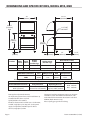
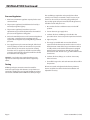
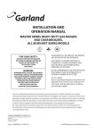
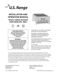
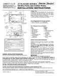
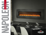
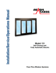
INSTALLATION AND
OPERATION MANUAL
GAS SINGLE AND DOUBLE OVENS
RESTAURANT SERIES MODEL G280-2
MASTER SERIES M1R AND M2R
FOR YOUR SAFETY:
DO NOT STORE OR USE GASOLINE
OR OTHER FLAMMABLE VAPORS OR
LIQUIDS IN THE VICINITY OF
THIS OR ANY OTHER
APPLIANCE
WARNING:
IMPROPER INSTALLATION, ADJUSTMENT,
ALTERATION, SERVICE OR MAINTENANCE
CAN CAUSE PROPERTY DAMAGE, INJURY,
OR DEATH. READ THE INSTALLATION,
OPERATING AND MAINTENANCE
INSTRUCTIONS THOROUGHLY
BEFORE INSTALLING OR
SERVICING THIS EQUIPMENT
PLEASE READ ALL SECTIONS OF THIS MANUAL
AND RETAIN FOR FUTURE REFERENCE.
THIS PRODUCT HAS BEEN CERTIFIED AS
COMMERCIAL COOKING EQUIPMENT AND
MUST BE INSTALLED BY PROFESSIONAL
PERSONNEL AS SPECIFIED.
IN THE COMMONWEALTH OF MASSACHUSETTS
THIS PRODUCT MUST BE INSTALLED BY A
LICENSED PLUMBER OR GAS FITTER. APPROVAL
NUMBER: G-1-07-05-28
For Your Safety:
Post in a prominent location, instructions to be
followed in the event the user smells gas. This
information shall be obtained by consulting
your local gas supplier.
Users are cautioned that maintenance and repairs must be performed by a Garland authorized service agent
using genuine Garland replacement parts. Garland will have no obligation with respect to any product that has been
improperly installed, adjusted, operated or not maintained in accordance with national and local codes or installation
instructions provided with the product, or any product that has its serial number defaced, obliterated or removed,
or which has been modified or repaired using unauthorized parts or by unauthorized service agents.
For a list of authorized service agents, please refer to the Garland web site at http://www.garland-group.com.
The information contained herein, (including design and parts specifications), may be superseded and is subject
to change without notice.
GARLAND COMMERCIAL INDUSTRIES
185 East South Street
Freeland, Pennsylvania 18224
Phone: (570) 636-1000
Fax: (570) 636-3903
Part##1382650
Rev44(12/07)
(12/07)
Part
1382650 Rev
GARLAND COMMERCIAL RANGES, LTD.
1177 Kamato Road, Mississauga, Ontario L4W 1X4
CANADA
Phone: 905-624-0260
Fax: 905-624-5669
Enodis UK LTD.
Swallowfield Way, Hayes, Middlesex UB3 1DQ ENGLAND
Telephone: 081-561-0433
Fax: 081-848-0041
© 2004 Garland Commercial Industries,
Inc.
Page
IMPORTANT INFORMATION
WARNING:
This product contains chemicals known to the state of california to cause cancer and/or birth defects
or other reproductive harm. Installation and servicing of this product could expose you to airborne
particles of glass wool/ceramic fibers. Inhalation of airborne particles of glass wool/ceramic fibers
is known to the state of california to cause cancer. Operation of this product could expose you to
carbon monoxide if not adjusted properly. Inhalation of carbon monoxide is known to the state of
california to cause birth defects or other reproductive harm.
Keep appliance area free and clear of combustibles.
Page Part # 1382650 Rev 4 (12/07)
TABLE OF CONTENTS
IMPORTANT INFORMATION . . . . . . . . . . . . . . . . . . . . . . . . . . . . . . . . . . . . . . . . . 2
DIMENSIONS AND SPECIFICATIONS, MODEL M1R, M2R . . . . . . . . . . . . . . . 4
DIMENSIONS AND SPECIFICATIONS, MODEL G280-2 . . . . . . . . . . . . . . . . . . 5
SPECIFICATIONS . . . . . . . . . . . . . . . . . . . . . . . . . . . . . . . . . . . . . . . . . . . . . . . . . . . . 6
Model G280-2 . . . . . . . . . . . . . . . . . . . . . . . . . . . . . . . . . . . . . . . . . . . . . . . . . . . . . . . . . . . . . . . . . . . 6
Models M1R and M2R. . . . . . . . . . . . . . . . . . . . . . . . . . . . . . . . . . . . . . . . . . . . . . . . . . . . . . . . . . . . 6
INSTALLATION . . . . . . . . . . . . . . . . . . . . . . . . . . . . . . . . . . . . . . . . . . . . . . . . . . . . . 6
Rating Plate. . . . . . . . . . . . . . . . . . . . . . . . . . . . . . . . . . . . . . . . . . . . . . . . . . . . . . . . . . . . . . . . . . . . . . 6
Gas Supply . . . . . . . . . . . . . . . . . . . . . . . . . . . . . . . . . . . . . . . . . . . . . . . . . . . . . . . . . . . . . . . . . . . . . . 6
Installation for Ovens Equipped with Casters. . . . . . . . . . . . . . . . . . . . . . . . . . . . . . . . . . . . . . 7
Installation for Ovens Equipped with Legs . . . . . . . . . . . . . . . . . . . . . . . . . . . . . . . . . . . . . . . . 7
Ventilation and Air Supply. . . . . . . . . . . . . . . . . . . . . . . . . . . . . . . . . . . . . . . . . . . . . . . . . . . . . . . . 7
Assembly of Battery. . . . . . . . . . . . . . . . . . . . . . . . . . . . . . . . . . . . . . . . . . . . . . . . . . . . . . . . . . . . . . 7
Pressure Regulators. . . . . . . . . . . . . . . . . . . . . . . . . . . . . . . . . . . . . . . . . . . . . . . . . . . . . . . . . . . . . . 8
Testing. . . . . . . . . . . . . . . . . . . . . . . . . . . . . . . . . . . . . . . . . . . . . . . . . . . . . . . . . . . . . . . . . . . . . . . . . . 8
OPERATION . . . . . . . . . . . . . . . . . . . . . . . . . . . . . . . . . . . . . . . . . . . . . . . . . . . . . . . . 9
Oven Lighting Procedure (All Models). . . . . . . . . . . . . . . . . . . . . . . . . . . . . . . . . . . . . . . . . . . . . 9
CLEANING AND MAINTENANCE . . . . . . . . . . . . . . . . . . . . . . . . . . . . . . . . . . . . . 9
Painted Finishes . . . . . . . . . . . . . . . . . . . . . . . . . . . . . . . . . . . . . . . . . . . . . . . . . . . . . . . . . . . . . . . . . 9
Stainless Steel Finishes. . . . . . . . . . . . . . . . . . . . . . . . . . . . . . . . . . . . . . . . . . . . . . . . . . . . . . . . . . . 9
Oven Interior (porcelain enamel) . . . . . . . . . . . . . . . . . . . . . . . . . . . . . . . . . . . . . . . . . . . . . . . . 10
Oven Interior, (optional continuous clean). . . . . . . . . . . . . . . . . . . . . . . . . . . . . . . . . . . . . . . . 10
OVEN PILOT ADJUSTMENT . . . . . . . . . . . . . . . . . . . . . . . . . . . . . . . . . . . . . . . . . . 11
TROUBLE SHOOTING . . . . . . . . . . . . . . . . . . . . . . . . . . . . . . . . . . . . . . . . . . . . . . . 11
Part # 1382650 Rev 4 (12/07)
Page DIMENSIONS AND SPECIFICATIONS, MODEL M1R, M2R
34"
[864mm]
33-1/4"
[845mm]
54-1/4"
[1378mm]
M2R
1-1/4" NPT
GAS INLET
30-1/4"
[768mm]
M1R
33-7/8"
[860mm]
14-1/4"
[362mm]
6"
[152mm]
Product
Width: Depth:
In(mm) In(mm)
M1R
34(864)
38(965)
M2R
34(864)
38(965)
Height:
In(mm)
(w/ NSF Legs)
36-3/8(924)
Height: In(mm)
(w/o NSF Legs)
30-3/8(772)
60-3/8(1534)
54-3/8(1381)
**RC oven is 25”(635mm) deep
INPUT-BTU/hr (Natural Gas)
M1R
kW Equivalent
34"
[864mm]
1-3/4"
[44mm]
Oven Interior: in(mm)
Width
Depth
Height
26-1/4(667)
29(737)**
13-1/2(343)
26-1/2(667)
292(737)
20-1/2(519)
M2R
kW Equivalent
Oven
40,000
11.72
80,000
23.44
TOTAL
40,000
11.72
80,000
23.44
RC=Range w/Convection Oven R=Range w/Oven S=Range w/Storeage Base T=Modular Top
INSTILLATION NOTES
Shipping Wt: (Lb/Kg)
Combustible Wall Clearances ¹
Entry Clearances
Operating Pressure
Sides: 6” (152mm)
Back: 6” (152mm)
Crated: 39-1/4”(997mm)
Uncrated: 34-1/4” (870mm)
Natural: 6 WC (15mbar)
Propane: 10 WC (25mbar)
M1R 480/220
M2S 480/220
¹NOTE: Installation clearance reductions are applicable only where local codes permit.
Data applies only to North America.
Gas input ratings shown here are for installations up
to 2,000 ft. (610m) above sea level.
Specify altitudes over 2,000 ft.
Electrical characteristics each RC oven: 1/3 HP motor,
120 VAC, single phase, 3.4 amps, 6 ft. (1.8m) power
supply cord provided, 230 VAC export is direct
connect, single phase, 50 Hz.
Page Commercial cooking equipment requires an adequate
ventilation system. For additional information, refer
to the National Fire Protection Association's standard
NFPA96. (North America only).
Please specify gas type when ordering.
Part # 1382650 Rev 4 (12/07)
DIMENSIONS AND SPECIFICATIONS, MODEL G280-2
Oven Interior Dimensions
Installation Clearances
Entry Clearances
Shipping Wt.
Height
Width
Depth
Sides
Rear
Crated
Uncrated
Lbs.
Kg
13-12"
(343mm)
26-1/4"
(667mm)
22"
(559mm)
6"
(152mm)
6"
(152mm)
46"
(1168mm)
34"
(864mm)
535
243
NOTE: Installation clearance reductions are applicable only where local codes permit.
This product is not approved for residential use.
Input Rating (Nat Gas)
Oven (each)
Operating Pressure
Natural
Propane
BTU
kW
"WC
mbar
"WC
mbar
30.000
8.78
4.5
11
10
25
Gas input ratings shown for installations up to 2000 ft., (610m), above sea level.
Please specify altitudes over 2000 ft.
3"
[76mm]
29"
[737mm]
7"
[178mm]
3/4" N.P.T.
REAR GAS
INLET
5"
[127mm]
FLUE
OPENING
4"
[102mm]
Commercial cooking equipment requires an
adequate ventilation system. For additional
information, refer to the National Fire Protection
Association's standard NFPA96..
30"
[762mm]
23-1/2"
[597mm]
58"
[1473mm]
53-1/2"
[1359mm]
23-1/2"
[597mm]
6"
[152mm]
Part # 1382650 Rev 4 (12/07)
15-1/2"
[394mm]
Page SPECIFICATIONS
Model G280-2
Models M1R and M2R
Oven interior dimensions are 26¼” wide (667mm) x 22” deep
x 13½” high (343mm), designed with embossed side liners
to achieve the maximum in thermal convection action for
uniform heat distribution and control. Oven sides, back, deck
and door linings coated in porcelain enamel make clean-up
easier and ensure long life. Burner compartment is lined
with corrosion resistant steel. Heavy oven rack provided (one
rack per oven standard), with adjustable in two positions.
Oven input is 35,000 BTU’s (10.25kW) per cavity. Individual
on-off valve and 100% safety pilot system provided as
standard equipment. Door springs and 100% safety pilot
system are located out of heat zone and easily accessible for
maintenance.
High capacity oven is 13½” high (343mm) x 26 ¼’ wide
(667mm) x 29” deep (737mm). Individual on-off valve, 100%
safety pilot and one heavy duty rack are standard. Oven
input is 40,000 BTU’s (11.72kW) per cavity.
Exclusive heat flow over design eliminates, hot spots and
gives consistently even oven temperatures. Oven sides, back,
deck and door linings coated in porcelain enamel make
clean-up easier and ensure long life. Door springs and 100%
safety pilot system are located out of heat zone and easily
accessible for maintenance.
INSTALLATION
Rating Plate
Gas Supply
When corresponding with the factory or your local
authorized factory service center regarding service problems
or replacement parts, be sure to refer to the particular unit
by the correct model number (including the prefix and suffix
letters and numbers) and the warranty serial number. The
rating plate affixed to the unit contains this information.
A. The type of gas for which the unit is equipped is stamped
on the data plate located behind the lower front panel.
Connect a unit stamped “Nat” only to natural gas; connect
those stamped “PRO” only to propane gas.
We suggest installation, maintenance and repairs should be
performed by your local authorized service agency listed in
your information manual pamphlet.
In the event you have any questions concerning the
installation, use, care or service of the product, write or call
our Product Service Department.
This product must be installed by professional personnel as
specified. Garland/U.S. Range products are not approved or
authorized for home or residential use, but are intended for
commercial applications only. Garland / U.S. Range will not
provide service, warranty, maintenance or support of any
kind other than in commercial applications.
Page B. If it is a new installation have the gas authorities check
meter size and piping to assure that the unit is supplied
with sufficient amount of gas pressure required to
operate the unit.
C. If it is additional or replacement equipment have gas
authorities check pressure to make certain that existing
meter and piping will supply fuel to the unit with not
more than ½” water column pressure drop.
NOTE: When checking gas pressure to be sure that all other
equipment on the same gas line is on. A pressure regulator
is supplied with model G280-2. A pressure regulator is not
supplied as standard equipment with models M1R and M2R,
however a 1-1/4” pressure regulator is sold as an option
with the original purchase. If you would like to purchase a
regulator after original purchase contact your equipment
Part # 1382650 Rev 4 (12/07)
INSTALLATION Continued
dealer. Installation must conform with the National Fuel Gas
Code ANSI Z223.1-1988 or latest edition, NFPA No. 54- Latest
Edition and National Electrical Code ANSI/NFPA 70-1990 or
latest edition and/or local code to assure safe and efficient
operation.
NOTE: The appliance and its individual shut-off valve (not
supplied by manufacturer) must be disconnected from
the gas supply piping system during any pressure testing
of that system at pressures in excess of ½ PSIG (3.45 KP2).
The appliance must be isolated from the gas supply piping
system by closing its individual manual shut-off (not
supplied by manufacturer) during any testing of the gas
supply piping system at test pressures equal to or less than
1/2 PSIG (3.45 KP2).
Installation for Ovens Equipped with Casters
A. The installation shall be made with a connector that
complies with the Standard for Connectors for Moveable
Gas Appliances, ANSI Z21.69/CSA 6.16, Addenda Z21.69B2006/CSA 6.16B-2006 (or latest edition), and a quickdisconnect device that complies with the Standard for
Quick Disconnects for Use with Gas Fuel, ANSI Z21.41/
CSA 6.9, Addenda Z21.41A-2005/CSA 6.16A-2005 (or
latest edition).
B. The front casters of the unit are equipped with brakes
to limit the movement of the oven without depending
on the connector and any quick disconnect device or its
associated piping to limit the appliance movement.
C. Please be aware, required restraint is attached to the
bracket (which is located on the rear caster closes to the
gas connection), and if disconnection of the restraint is
necessary, be sure to reconnect the restraint after the
oven has been returned to its originally installed position.
Installation for Ovens Equipped with Legs
Raise front of the unit and block. Do not lay unit on its back.
Position leg insert into leg retainer opening and tap up until
it seats at collar flange. Repeat at rear of unit making sure all
four legs are adjusted to same height. Legs can be adjusted
to overcome an uneven floor.
Ventilation and Air Supply
Proper ventilation is highly important for good operation.
The ideal method of ventilating a range is the use of a
properly designed canopy which should extend six inches
(6”) beyond all sides of the appliance and six feet (6’) six
inches (6”) from the floor.
Part # 1382650 Rev 4 (12/07)
A strong exhaust fan will create a vacuum in the room for an
exhaust system vent to work properly, replacement air must
enter the room in which the vent is located.
All gas burners and pilots need sufficient air to operate and
large objects should not be placed in front of this oven which
would obstruct the air flow through the front.
Assembly of Battery
This section pertains to Master Series models only.
All heavy duty batteried equipment is aligned and fitted at
the factory, from left to right and must be installed in this
order. There is a diagram provided with every heavy duty
battery.
A. All such units should be placed in their respective battery
position. Detach valve panels to prevent damage,
remove them from the area where the battery is being
assembled.
B. Level each unit (to the oven rack) by adjusting the six inch
(6”) legs (refer back to Item 1 for limitations), or where
legs are not used, adjust level with shims. Readjust legs, if
required.
C. Connect units together by mating the unions at each
end of the manifold. (Adjoining units must have
matching unions, unless the union parts are of the
same specifications, a leak proof connection cannot be
assured.) Hand tighten unions at this point.
D. The units should be fastened at the rear by inserting
5/16” bolts through the holes provided at the rear of the
burner box sides. Be sure of proper unit alignment in the
battery before final tightening of these bolts or unions.
Improper tightening will cause the “fanning” or “bowing”
of batteries units.
The final tightening of the union should be accomplished
by using a suitable spanner wrench. If such a wrench is
not available, the Garland union collar has special ridges,
and a cold chisel can be driven against these ridges to
properly seat and seal the union.
E. The manifold of this unit or the manifold of which is
a part of must be equipped with a certified pressure
regulator suitable for battery application and adjustable
for an outlet pressure at the manifold as specified on the
rating place.
Page INSTALLATION Continued
Pressure Regulators
1. Must have a maximum regulation capacity for the total
connected load.
2. The pressure regulator(s) installed must be listed by a
nationally recognized agency.
3. The pressure regulator(s) must have a pressure
adjustment range to allow adjustment to the manifold
pressure on the appliance rating plate.
4. Unless the manifold pressure on all connected appliances
is the same, a separate pressure regulator must be
supplied for each appliance(s) having differing manifold
pressures.
5. Gas supply lines may be connected at right, left or both
ends of a battery or at the tee connections on spreader
plates. If five (5) or more units are placed in a battery,
more than one (1) supply line should be used. A readily
accessible, approved type of hand shut-off valve should
be installed on each supply line.
WARNING: Local codes may require that the pressure
regulator be externally vented. This will be supplied by
others.
Testing
All fittings and pipe connections must be tested for
leaks. Use approved gas leak detectors, soap solutions or
equivalent, checking over and around the fittings and pipe
connections. DO NOT USE A FLAME! Accessibility to all gas
Page lines and fittings require that valve panel(s) lower front
panel(s), oven rack(s) be removed. It may be necessary to
remove or at least raise and securely prop griddles, hot
tops and top grates. All parts removed (including fasteners)
should be stored safely for re-use.
1. Be sure that all valves and thermostats are in the ‘off’
position.
2. Turn on the main gas supply valve.
3. Leak test all valves and fittings as described in the
procedure above. Correct any leaks required and recheck.
4. Light oven pilot.
5. The range is provided with an oven shut-off valve
separate from the thermostat, turn this valve on and set
the thermostat at 500°. If the range oven thermostat has
an “off” position on the dial the thermostat is equipped
with an internal, integral oven shut-off valve. Set this
thermostat to 500°. In both cases, gas will now flow to the
oven burner.
6. Leak test all valves, fittings, etc. as above. Correct any
leaks and retest.
7. Shut off all range valves and set thermostat dials to ‘off’ or
low position.
All units are tested and adjusted at the factory. However,
burners and pilots should be checked at installation and
adjusted if necessary.
Part # 1382650 Rev 4 (12/07)
OPERATION
Oven Lighting Procedure (All Models)
Lighting
1. Remove oven bottoms.
2. Depress and hold reset button (red) extending through
the louvered panel (beneath the oven door) while
lighting the oven pilot. Continue to depress the reset
button for 60 seconds. Release button. If pilot does not
stay lit, repeat this procedure after 5 minutes.
LIGHT BURNER THRU INSIDE OF OVEN
W/MATCH
Shut down
1. Turn all valves and thermostats to the off position.
2. If range is to be shut down for an extended period of
time, close the in line gas valve.
Re-lighting
1. Shut all gas valves off.
2. Wait 5 minutes.
3. Repeat lighting instructions in section “A” above.
RESET BUTTON ON SAFETY
CLEANING AND MAINTENANCE
Establish a regular cleaning schedule. Any spills should be
wiped off immediately.
Painted Finishes
The oven should be permitted to cool down before cleaning
exterior surfaces. Wipe exposed, cleanable surface when cool
with a mild detergent and hot water. Stubborn residue spots
may be removed with a light weight non metallic scouring
pad. Dry thoroughly with a clean cloth.
NOTE: Many parts of the commercial range are raw steel, (i.e.
springs, door hooks, etc.) and can react to moisture, forming
rust. This occurrence is normal and not considered a factory
detect. Clean with a stainless steel or fiber pad. A coating of
salt free oil may be applied.
Part # 1382650 Rev 4 (12/07)
Stainless Steel Finishes
For routine cleaning just wash with a hot water and
detergent solution. Wash just a small area at a time or the
water will evaporate leaving the chemicals behind causing
streaking.
Rinse the washed area with a clean sponge dipped in a
sanitizing solution and wipe dry with a soft cloth before it
can dry.
Use a paste (of water and a mild scouring powder) if you
have to, but never rub against the grain. All stainless steel
has been polished in one direction. Rub with the polished
lines to preserve the original finish. Then thoroughly rinse
as before. To prevent finger prints there are several stainless
steel polishes on the market that leave an oily or waxy film.
Do not use on surfaces that will be in contact with food.
Page CLEANING AND MAINTENANCE Continued
Stainless steel may discolor if overheated. These stains can
usually be removed by vigorous rubbing with a scouring
powder paste.
Use only stainless steel, wooded or plastic tools if necessary
to scrape off heavy deposits of grease and oil. Do not use
ordinary steel scrapers of knives as particles of the iron may
become imbedded and rust. STEEL WOOL SHOULD NEVER
BE USED. Either a typical bleach solution or hot water can be
used to sanitize stainless steel with out harm.
Oven Interior (porcelain enamel)
NOTE: Disconnect line cord (if applicable) from power
supply before cleaning or servicing.
1. Before cleaning oven interior, remove all oven racks
and guides (if “RC” base). Oven racks and guides can be
cleaned with a mild soap and warm water or run through
dish washer.
2. The porcelain interior can be cleaned with oven cleaners
such as “Easy-Off”, or “Dow Oven Cleaner”. Apply only
when oven is cold.
Oven Interior, (optional continuous clean)
NOTE: Disconnect line cord (if applicable) from power
supply before cleaning or servicing.
1. “Break-In Period” – When the oven is new, operate the
oven for at least two hours at high heat, with the oven
empty, before normal cooking operation. Continue
preheating the oven for two hours prior to use during
the first two weeks. During this break-in period, it is
important that the oven surfaces be kept clean of
excessive soiling due to spillage.
Page 10
2. How to put “continuous cleaning” action to work: each
day, after baking and roasting operations have ceased
empty the oven, turn the temperature control up to high
heat (500°). This high heat will accelerate the cleaning
action and reduce the time required to effectively clean
the oven. Usually the cleaning operation will take about
45 to 60 minutes.
3. Heavy Staining – When the oven appears soiled, due to
heavy staining, we suggest pre-heating the empty oven
each day for 1 or 2 hours (depending on the condition of
the oven) for effective results. Also, ordinary household
ammonia has proven to be effective in removing bakedon “soil” build-up and has the beneficial effect of keeping
the microscopic “pores” of the coating open and free
To perform its cleaning action. An occasional light
swabbing with household ammonia while the oven is at
room temperature will prove extremely beneficial.
Abrasives should not be used – in order to maintain
continuous cleaning action, it is very important to avoid
the use of abrasive materials such as steel wool scouring
pads, abrasives or sharp implements which can cause
permanent damage to the surface coating. In addition
oven cleaners such as “easy-Off” or “Dow Oven Cleaner”
will clog the “pores” of the special coating and will retard
the cleaning action.
4. Period “Tune-Up” – Although the oven appears clean, we
recommend operating the oven at high heat for 2 hours
approximately once each month. This will insure against
build-up of solids in hard to see places and in the pores of
the coating.
Part # 1382650 Rev 4 (12/07)
OVEN PILOT ADJUSTMENT
The oven pilot should be adjusted to stable flame 1”
long with no yellow tips. This flame should envelope
the thermocouple end for 3/8” to 1/2” and will cause
the thermocouple tip to glow a dull red. The oven pilot
adjustment valve is found on the manifold behind the valve
panel.
TROUBLE SHOOTING
Cakes are dark on the sides and not done in the center
Lower oven temperature
Cake edges are too brown
Reduce number of pans or lower temperature
Cakes have light outer color
Raise temperature
Cake settles slightly in the center
Bake longer or raise oven temperature slightly. Do not open
doors to oven for long periods.
Cake ripples
Overloading pans or batter is too thin
Cakes are too coarse
Lower oven temperature.
Pies have uneven color
Reduce number of pies per rack or eliminate use of bake
pans.
Cupcakes crack on top
Lower oven temperature.
Meats are browned and not done in the center
Lower oven temperature and roast longer.
Meats are well done and not browned
Raise temperature. Limit amount of moisture.
Meats develop hard crust
Reduce temperature or place pan of water in oven
Part # 1382650 Rev 4 (12/07)
Page 11