1
DOPPLER SONAR
DS-30
www.furuno.co.jp
All brand and product names are trademarks, registered trademarks or service marks of their respective holders.
The paper used in this manual
is elemental chlorine free.
・FURUNO Authorized Distributor/Dealer
9-52 Ashihara-cho,
Nishinomiya, 662-8580, JAPAN
Telephone : +81-(0)798-65-2111
Fax
: +81-(0)798-65-4200
All rights reserved.
Printed in Japan
A : MAY 1993
T : SEP . 16, 2009
Pub. No. IME-72360-T
(TATA )
DS-30
*00080474613*
*00080474613*
* 0 0 0 8 0 4 7 4 6 1 3 *
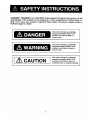
WARNING
CAUTION
Only qualified personnel
Ground the equipment.
should work inside the
equipment.
Ungrounded equipment can
give off or receive electromagnetic interference or
cause electrical shock.
This equipment uses high
voltage electricity which can
shock, burn, or cause death.
Confirm that the power supply voltage
is compatible with the voltage rating
of the equipment.
Turn off the power at the ship's
mains switchboard before beginning
the installation. Post a warning
sign near the switchboard to ensure
that the power will not be applied
while the equipment is being
installed.
Connection to the wrong power supply
can cause fire or equipment damage.
The voltage rating appears on the label
at the rear of the equipment.
Serious injury or death can result if the
power is not turned off, or is applied while
the equipment is being installed.
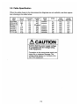
Observe the following compass safe
distances to prevent interference to a
magnetic compass:
Standard
compass
(m)
ii
Steering
compass
(m)
Main display
DS-300
0.75
0.50
Operation panel
DS-301
0.2
0.2
Processor unit
DS-310
1.3
1.0
Digital indicator
DS-350
0.3
0.2
Digital indicator
DS-351
0.4
0.3
Distribution unit
DS-370
0.9
0.7
Analog indicator
DS-381/382
0.7
0.6
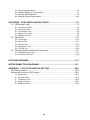
TABLE OF CONTENTS
Complete Set ........................................................................................................................ 1
Installation Materials ............................................................................................................. 3
CHAPTER 1. GENGERAL ................................................................................. 1-1
1.1 Selecting Mounting Location...................................................................................... 1-1
1.1.1 Transducer (Hull Unit) ..................................................................................... 1-1
1.1.2 Other Indoor Units ........................................................................................... 1-2
1.2 Grounding.................................................................................................................. 1-3
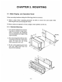
CHAPTER 2. MOUNTING.................................................................................. 2-1
2.1 Display Unit and Operation Panel .............................................................................. 2-1
2.1.1 Standard Mounting .......................................................................................... 2-1
2.1.2 Mounting with Fixing Plate............................................................................... 2-2
2.2 Processor Unit ........................................................................................................... 2-4
2.3 Transceiver Unit......................................................................................................... 2-4
2.4 Junction Box .............................................................................................................. 2-4
2.5 Transducer (Hull Unit)................................................................................................ 2-5
2.6 Rate-of-Turn Gyro Unit (Option)................................................................................. 2-7
2.6.1 Mounting Procedure ........................................................................................ 2-7
2.6.2 Leveling Adjustment ........................................................................................ 2-8
CHAPTER 3. WIRING ........................................................................................ 3-1
3.1 Precautions for Cable Installation............................................................................... 3-1
3.1.1 Cable between hull Unit (transducer) and Transceiver .................................... 3-1
3.1.2 Cable between transceiver Unit and Processor Unit (via Junction Box)........... 3-1
3.1.3 Other Connection Cables of DS-30 ................................................................. 3-1
3.2 Cable Specification .................................................................................................... 3-2
3.3 Cable Fabrication....................................................................................................... 3-5
3.3.1 Transducer Cable............................................................................................ 3-5
3.3.2 Cables between Transceiver Unit/Junction Box/Processor Unit (TTYCY-16S). 3-5
3.3.3 Cables between Processor Unit/Main Display Unit/Sub Display Unit
(CO-SPEVV-SB-C 0.2x10P)............................................................................ 3-6
3.3.4 CIF/NMEA Data Signal Cable (CO-SPEVV-SB-C 0.2x5P)............................... 3-8
3.3.5 Other Cables ................................................................................................... 3-9
3.3.6 Insulation of cables for transducer................................................................. 3-10
3.4 Remarks on Connection with Other Equipment........................................................ 3-11
3.4.1 KP Input Signal for Interference Rejection ..................................................... 3-11
3.4.2 CIF/NMEA Signal I/O Circuit.......................................................................... 3-11
3.4.3 Requirement of Wind Direction and Speed Signal ......................................... 3-11
3.4.4 Requirement in Engine Revolution Speed Signal........................................... 3-11
3.4.5 Connection of Gyro Signal (RS-232C)........................................................... 3-12
CHAPTER 4. POST-INSTALLATION SETTING ................................................ 4-1
4.1 DIP Switch Setting ..................................................................................................... 4-1
4.1.1 Display Unit ..................................................................................................... 4-1
4.1.2 Processor Unit................................................................................................. 4-2
4.1.3 Distribution Box ............................................................................................... 4-3
4.1.4 Digital Indicator DS-351 (option)...................................................................... 4-4
4.2 Setting Offset Data Menu........................................................................................... 4-5
4.3 Setting System Menu................................................................................................. 4-7
4.3.1 Opening System Menu.................................................................................... 4-7
iii
4.3.2 Closing System Menu....................................................................................... 4-7
4.3.3 Setting Display Unit Preset Menu ..................................................................... 4-7
4.3.4 Setting Ship Data Menu.................................................................................... 4-9
4.3.5 Setting External Sensor Menu .........................................................................4-10
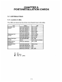
CHAPTER5.POST-INSTALLATION CHECK .................................................. 5-1
5.1 LED Status Check........................................................................................... 5-1
5.1.1 Location of LEDs .............................................................................................. 5-1
5.1.2 Processor Unit.................................................................................................. 5-2
5.1.3 Transceiver Unit ............................................................................................... 5-6
5.1.4 Rate-of-Turn Gyro ............................................................................................ 5-8
5.1.5 Distribution Box ................................................................................................ 5-9
5.2 Self-Check..................................................................................................... 5-11
5.2.1 Procedure........................................................................................................5-11
5.2.2 Panel Test .......................................................................................................5-11
5.2.3 Single Test ......................................................................................................5-12
5.2.4 Continuous Test ..............................................................................................5-15
5.2.5 TX/RX Test......................................................................................................5-16
5.3 Checking External Noise and interference .................................................... 5-17
5.3.1 External Noise Check ......................................................................................5-17
5.3.2 interference Check ..........................................................................................5-18
OUTLINE DIAGRAMS...................................................................................... D-1
INTERCONNECTION DIAGRAMS ..................................................................S-1
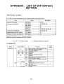
APPENDIX.LIST OF DIP SWITCH SETTING .............................................. AP-1
DIP Switch Location..............................................................................................AP-1
Setting and Function of DIP Switch ......................................................................AP-1
1)
2)
3)
4)
5)
Display Unit ......................................................................................................AP-1
Processor Unit ..................................................................................................AP-2
Transceiver Unit ...............................................................................................AP-8
Digital Indicator.................................................................................................AP-7
Distribution Unit ................................................................................................AP-8
iv
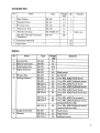
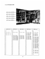
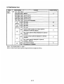
No.
Name
9
Distance Indicator
10
Alarm Unit
2
Type
MF-22T-1
MF-22T-2
MF-22T-3
AU-12
Weight
(kg)
6.0
9.0
6.0
0.6
Remarks
Flush mount
Bulkhead mount
Tabletop mount
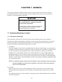
CHAPTER 1. GENERAL
The Furuno model DS-30 Doppler Sonar provides accurate measurement of the fore/aft and
port/starboard speed of vessels. It mainly consists of display unit, processor unit, junction box,
transceiver unit and transducer (hull unit).
NOTICE
Do not apply paint, anti-corrosive sealant
or contact spray to coating or plastic
parts of the equipment.
Those items contain organic solvents that
can damage coating and plastic parts,
especially plastic connectors.
1.1. Selecting Mounting Location
1.1.1 Transducer (Hull Unit)
The performance of the DS-30 is directly related to the mounting location of the transducer.
Especially air bubbles and turbulence caused by movement of the ship and interference from other
acoustic equipment seriously degrade performance. The mounting location should, therefore, be
determined carefully, keeping the following factors in mind.
1) Air Bubbles
Since the transducer of the DS-30 is installed flush with the ship’s hull bottom, it is susceptible to
air bubbles which flow below the hull bottom. Select a location where air bubbles created at ship’s
bow do not go down to the mounting location. When the ship has a bulbous bow, install the
transducer in it or just behind it. However, when the ship makes a voyage in high latitude area
breaking through ice flows, avoid the location where broken ice flows may strike the location.
The DS-30 is used not only for ocean going navigation but also for docking to loading/unloading
facilities, at which the bow and side thrusters are used. The transducer should be separated at least
4 or 5 meters from them.
NOTE: In extremely shallow harbors with soft bottom, whirls created by ship’s movement
cause air bubbles and also bottom materials to be stirred, which may make the
use of DS-30 impossible.
2) Cavitation
Dents on ship’s bottom cause whirls behind them and may sometimes cause cavitation which
adversely affects the performance of the transducer, especially when the ship moves at a high
speed.
The welded portion between the transducer casing and the ship’s hull should therefore be finished
as smooth as possible.
1-1
3) Variation of Draft Level
When the ship travels unloaded, the draft level goes low and air bubbles are apt to be pushed
down to the transducer location. This occurs especially when the water level is lower than the
center line of the bulbous bow. It is recommended to load a proper amount of ballast not only for
the DS-30 but also for safety of navigation.
4) Interference of Other Ultrasonic Equipment
If integer multiple of the transmission frequency of other ultrasonic equipment is within 440 ± 8
kHz, interference may occur. Select a location at least 1 m away from the transducer of the
ultrasonic equipment and change, if possible, the direction of its transmission beam so that the
beam may not cross the beam of DS-30.
5) Installation in Dangerous Place
Do not install the transducer in the oil tank, oil room, LPG gas room and freezing room.
6) Maintenance Space
The transducer is detachable/replaceable in the water from outside the ship.
1.1.2 Other Indoor Units
All units are designed and constructed to withstand humidity and corrosive atmosphere common to a
vessel. However certain guidelines must be observed to ensure continued operation. When selecting a
mounting location, keep the following points in mind.
1) Avoid place subject to high temperature/humidity. This includes heat emitting apparatuses and
sunshine.
2) Avoid places subject to sea splash. Sea splashes most assuredly damage the sensitive components
inside units.
3) Locate the units where they will not become soiled easily. Never locate it near exhaust pipes.
4) Select a place where vibration is minimal.
5) Select a place with sufficient ventilation.
1-2
3. Fix the junction box by tightening the bolts with nuts placed from back of the installation
location.
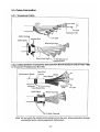
2.5. Transducer (Hull Unit)
For transducer /casing DS-330/311, refer to the installation instructions on page 2-5.
For gate value seachest DS-335, refer to the installation instructions on page D-9. Note that the
spacer and upper plate should be oriented to the ship’s bow.
2-5
1
2
3
4
5
2-6
6
HULL UNIT INSTALLATION
CONDUIT PIPE
CABLE GLAND
A
800
800
25
2-φ15
10
φ80
3
4
5
16
b) Orientation and leveling errors can be offset on the data offset
menu in the display unit. Install the casing as follows.
Fore-aft orientation: Align the bow mark on the casing with ship's
fore-aft line to an accuracy within 1 degree.
Leveling: Install the casing so that the top face of the casing
is horizontal during navigation. Measure leveling accuracy with
a level meter, after the ship is launched.
c) Detach transducer (1), cable, cable gland (5) and gasket (3) before
welding the casing.
d) Welding method for casing and ship's hull should be determined by the
shipyard. Weld reinforcement ribs to the casing if the shipyard
considers them necessary.
e) Remove welding build up between the casing and the ship's hull (part
marked ※1 in the drawing) with a grinder, for a flat finish.
a) Lead the transducer cable into the casing up to the white line mark on
LINE
WATERTIGHT
25
the cable and tighten the cable gland with the cable gland spanner
15
CONNECTOR
supplied.
7 8 9
b) Install locking bolt (15) after the cable gland is tightened.
c) Remove dirt and apply silicone grease onto the side of receptacle
2
on the transducer before plugging the watertight connector.
d) To plug in the watertight connector, pull up the ring and insert the
※1
※1
HULL PLATE
φ315
connector into the receptacle, and then fix the connector holder (6)
GROOVE DEPTH TO BE DETERMINED BY SHIPYARD.
with hex nut (7).
1 14 12 11 10
13
340
410
SEE NOTE2
Lay the cable from the casing to the transceiver unit
inside a conduit pipe and fill the conduit pipe with
sand or other appropriate materials to prevent cable
vibration.
8) PAINTING
Shop primer coating (Epcom Zinc Rich Primer B) has
been applied to the casing. Paint both inner and outer
surfaces on the casing with the paint used for top
coating of the ship's hull bottom.
NOTE 1: The transducer surface is coated with antifouling paint Marine Star 20. Do not coat it by other
type of paint.
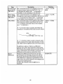
9) TESTING AFTER INSTALLATION
5) FIXING/CONNECTING TRANSDUCER CABLE
6
B
7) CABLING
Comfirm the ohm value of terminals on the transducer.
A digital ohmmeter is recommended.
Do not use a megohmmeter.
TYPE OF SIGNAL
TEST POINT
STANDARD(Ω)
BEAM 1 (BLK)
TB #1(RED) - #2(BLK)
0.5~3.0
BEAM 2 (RED)
TB #4(RED) - #5(BLK)
0.5~3.0
BEAM 3 (GRN)
TB #7(RED) - #8(BLK)
0.5~3.0
TEMP SENSOR 1
TB #10(YEL) - #11(WHT)
450~550
TEMP SENSOR 2
TB #13(BLU) - #14(GRY)
450~550
(GRIND WELDING BUILD UP.)
⑥ Connector Holder
C
Ring
1) CHECKING MATERIAL AND THICKNESS OF TRANSDUCER CASING
Before starting the installation work, check that the transducer casing
is of a material approved by ship classification society concerned and
with a thickness not thinner than the hull plate. The standard tank
supplied by FURUNO is of material KSTPG370(KSTPG38,KST138), approved
by ship Classification Society of Japan, with a thickness of 25 mm.
NOTE 2: The inside of transducer tank (16) and
bolt(10)-thru hole will be filled with water.
It has no problem.
Cable
SILICONE SEALANT
Silicone Grease
(Thine Coating)
DETAIL FOR FIXING BOLT AND BOLT CAP
2) DETERMINING INSTALLATION SITE
Select the installation site reffering to the recommended sites described
in the installation instructions.
For ships prone to collect air bubbles under the hull bottom, consult
your local FURUNO office or agent for advice.
D
3) CONSTRUCTING WATERPROOF COMPARTMENT FOR TRANSDUCER CASING
The compartment for the transducer casing is not compulsory required by
law because the transducer casing is waterproof. However it is recommended
to construct it for safety. Dimensions shown above are only for reference;
shipyard may change as required. Since the transducer is detachable/
replaceable in water from outside the ship, maintenance space is not
required inside the compartment.
4) WELDING CASING
a) Fore/aft marks are engroved on the casing. Align them with ship's
fore-aft line.
12 11 10
13
6) FIXING TRANSDUCER
Twisting the cable (namely, rotating the transducer by about one turn),
align the bow mark on the transducer with ship's bow and fix the transducer
by using hex bolt (10). After apply silicone sealant to bolt-head, put
bolt cap (13) onto it.
DRAWN
Jul. 26 '06 T.YAMASAKI
CHECKED
Jul. 26 '06 T.TAKENO
APPROVED
Jul. 27 '06 T.Matsuguchi
MASS
SCALE
kg
DWG No.
TITLE
NAME
DS-330/331
HULL UNIT
INSTALLATION PROCEDURE
DS-30
REMARKS
E7236-Y10- J
FURUNO ELECTRIC CO., LTD.
3 - 3
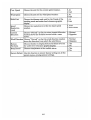
3) Wire Crimping Procedure
1. Strip the vinyl sheath of the wire to expose the core by 3mm
to 4mm.
2. Hold the crimping tool horizontally and insert the contact pin
with its slit faced downward into the crimp hole on the
crimping tool.
3. Insert the wire onto the contact pin and squeeze the handle
until the ratchet releases. Note that the wire should be
inserted deep enough until its end comes in contact with the
stopper plate of the crimping tool. After crimping, pull the wire
to make sure that it is securely fixed.
4) Inserting Contact Pin into Connector Housing
The connect pins fitted to wires should be inserted into the
connector housing referring to the interconnection diagram.
5) Procedure to Extract Contact Pin
When a contact pin is inserted into an incorrect hole on the
connector body, take it out by using the pin extractor.
1. Push the pin extractor into the pin hole from the side opposite
to the pin inserting side.
2. Push in the head of the pin extractor, and the contact pin is
unlocked and pushed out.
Cable out going direction
6) Assembling Connector Housing
1.
2.
3.
4.
Fix the cover 1 , paying attention to the cable outgoing direction.
Dress the wires and put covers 2 and 3 on.
Use a fragment of cable sheath to fix the wires with the connector clamp.
Cut the unused wires to proper length and wrap their ends with vinyl tape.
Note) Covers 1 , 2 and 3 are not fitted on the connectors connected to the
main and sub display units.
3-7
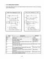
7) Clamping Cable
Clamp the shield and armor of the cable with cable clamp.
Cable Clamp
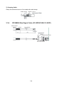
3.3.4
Shield + Armor
CIF/NMEA Data Signal Cable (CO-SPEVV-SB-C 0.2X5P)
Anticorrosive
Armor
Sheath
Vinyl sheath
Socket-set Screw
Connector Case
3-8
Pin
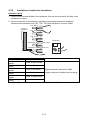
3.3.5
Other Cables
All other cables are connected to terminal boards. Fabricate their ends as follows.
1) Cable Armor
<For cables led in through cable clamp>
Expose the armor and clamp it with the cable clamp.
Cable Clamp
<For cables led in through cable gland>
Solder a vinyl sheath wire to the armor and connect it to the grounding terminal.
Bare wire
Vinyl Sheath Wire
To Earth Terminal
Soldering
2) Cable Shield
<For individual shield>
Undo individual shields only near at the terminal boards to which the wires are connected.
Further, tape shields for insulation.
Individual Shield
Vinyl Sheath
<For common shield>
Undo common shield at entrance of the unit and tape it for insulation.
Common
shield
Vinyl Tape
3-9
3.3.6
Insulation of cables for transducer
Insulation check
1. Remove all cores and shields of the transducer from the terminal board. All wires of the
transducer are open.
2. Set the multimeter to the maximum resistance range and measure the resistance
between each transducer line (TD1, TD2, TD3) and individual or common shield.
TD
Black
Red
Black
Cable of
transducer
TD
Red
Red
Black
TD
Green
Red
Black
Multimeter
Temperature Sensor 1 Yellow, White
Temperature Sensor
Blue, Grey
Measurement places
Insulation resistance value
- polarity lead
- polarity lead
Red wire of black
Shield in black sheath
sheath
Red wire of black
Common shield
sheath
Red wire of red
Shield in red sheath
Digital multimeter: More than 10MΩ
sheath
Red wire of red
Analog multimeter: Needle does not swing.
Common shield
sheath
Red wire of green
Shield in green sheath
sheath
Red wire of green
Common shield
sheath
Note) If rating is not met a location, suspect faulty insulation. Replace a new one.
3-10
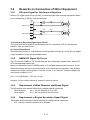
3.4
Remarks on Connection of Other Equipment
3.4.1
KP input Signal for Interference Rejection
When a TX trigger pulse (Keying Pulse) is connected from other acoustic equipment which
gives interference to DS-30, note the following.
TB3
External KP1
External KP2
1
2
3
4
5
6
22Ω
4mA
22Ω
22Ω
4mA
22Ω
1) Interference Rejection Signal Input Circuit
Two iuput ports are provided in the processor unit for connection of KP for interference
rejection. Use any one of them.
2) Current Requirement
Recommended current is 4 mA while the circuit operates normally at 2 mA to 20 mA. Adjust
output resistance for the recommended current.
3.4.2
NMEA/CIF Signal I/O Circuit
The I/O circuit for NMEA or CIF format data has the configuration shown below, where CIF
is Furuno standard data format.
Maximum allowable current in NMEA output is 25 mA and recommended current is 10 mA.
When terminating the line by a photo-coupler for a current loop configuration, take suitable
means at the signal receiving side to limit the current. If, for example, forward voltage drop
in the photo-coupler is 2.2V:
[4.8 – 2.2 (V)]/[10(mA)] – 227 (Ω) = 33 (Ω)
therefore, 33 ohm resistor should be inserted in series in the line.
3.4.3
Requirement of Wind Direction and Speed Signal
The wind meter that outputs following dc voltages can be connected.
-Wind direction:
0 to 1 Vdc for direction of 0° to 540°
-Wind speed:
0 to 1 Vdc for speed of 0 to 60 m/sec
3.4.4
Requirement in Engine Revolution Speed Signal
The engine tachometer that outputs following dc voltage can be connected.
0 to 1 Vdc for revolution speed of 0 to full scale.
3-11
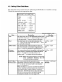
L6
Set horizontal distance between keel and nav-equipment
antenna.
Set distance between DS-30 and #1 echo sounder
transducers.
Set distance between DS-30 and #2 echo sounder
transducers.
D1
D2
-B/2 to B/2 m
0.0 to (Loa-L1) m
0.0 to (Loa-L1) m
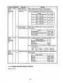
4.3.5 Setting External Sensor Menu
EXTERNAL SENSORS
Item
GYROCOMPASS
: Yes
R. O. T. GYRO
: Yes
NAV SENSOR
WIND METER
: No
: No
TACHOMETER
: No
CLINOMETER
: No
END
Description
Selection
GYROCOMPASS Choose YES if a gyrocompass is connected.
Yes/No
R.O.T GYRO
Choose YES if a laser rate of turn gyro is connected.
Yes/No
NAV SENSOR
Choose YES if a nav-sensor is connected.
Yes/No
WIND METER
Choose YES if a wind meter is connected.
Yes/No
TACHOMETER
Choose YES if main engine is tachometer is connected.
Yes/No
CLINOMETER
Choose YES if a clinometers is connected.
Yes/No
4-10
ဳฬ㧛ⷙᩰ
&'5%4+26+105
ᢙ㊂
36;
↪ㅜ㧛⠨
4'/#4-5
*':076
ⷺ㩏㨹㩎㩆㨷
(.#69#5*'4
㩚㩀㩨㩁ᐔᐳ㊄
524+0)9#5*'4
㩔㩨㩒ᐳ㊄
%4+/210.7)
⌕┵ሶ
%106#%62+0
㩄㩧㩊㩂㩎㩕㩩㩧
%100'%614
㩄㩒㩂㩊
'#46*2.#6'
㨻㨺㩇㌃᧼㧖㋕ઃ㧖
%1&'01
/575
%1&'01
/575
%1&'01
/575
%1&'01
(8/
.(
%1&'01
(
%1&'01
8(
%1&'01
:://
ဳฬ㧛ⷙᩰ
&'5%4+26+105
ᢙ㊂
36;
↪ㅜ㧛⠨
4'/#4-5
ڏ
㧲㨁㧾㨁㧺㧻ޓ㧱㧸㧱㧯㨀㧾㧵㧯ޓ㧯㧻ޓ㧚㧘㧸㨀㧰
㧔⇛࿑ߩኸᴺߪޔෳ⠨୯ߢߔ&ޓޕ+/'05+105+0&4#9+0)(144'('4'0%'10.;㧕
#/:
㧲㨁㧾㨁㧺㧻ޓ㧱㧸㧱㧯㨀㧾㧵㧯ޓ㧯㧻ޓ㧚㧘㧸㨀㧰
㧔⇛࿑ߩኸᴺߪޔෳ⠨୯ߢߔ&ޓޕ+/'05+105+0&4#9+0)(144'('4'0%'10.;㧕
#/:
6916;2'5#0&%1&'5/#;$'.+56'&(14#0+6'/6*'.19'4241&7%6/#;$'5*+22'&+02.#%'1(6*'722'4241&7%6
37#.+6;+56*'5#/'
⇛ޓޓ࿑
176.+0'
#/: ဳᑼ㩄㨺㩎㩨⇟ภ߇㧞Ბߩ႐วޔਅᲑࠃࠅᲑߦઍࠊࠆㆊᷰᦼຠߢࠅޔ߅ߥޓޕߔ߹ߡߞ߇߆ࠄߜߤޔຠ⾰ߪᄌࠊࠅ߹ߖࠎޕ
%1&'01 %152'885$%:2
%152'885$%ޓ2:.(
ฬޓޓ⒓
0#/'
%2
6916;2'5#0&%1&'5/#;$'.+56'&(14#0+6'/6*'.19'4241&7%6/#;$'5*+22'&+02.#%'1(6*'722'4241&7%6
37#.+6;+56*'5#/'
2#+4%#$.'
ኻ㩃㨺㩖㩨㩣
⇟ภ
01
6;2'
%1&'01
A-2
ဳᑼ㩄㨺㩎㩨⇟ภ߇㧞Ბߩ႐วޔਅᲑࠃࠅᲑߦઍࠊࠆㆊᷰᦼຠߢࠅޔ߅ߥޓޕߔ߹ߡߞ߇߆ࠄߜߤޔຠ⾰ߪᄌࠊࠅ߹ߖࠎޕ
⇛ޓޓ࿑
176.+0'
+056#..#6+10/#6'4+#.5
ฬޓޓ⒓
0#/'
+056#..#6+10/#6'4+#.5
⇟ภ
01
Ꮏ᧚ᢱ
#/: Ꮏ᧚ᢱ
6;2'
%1&'01
A-1
*':076
ⷺ㩏㨹㩎ޓ㧝⒳
524+0)9#5*'4
㩔㩨㩒ᐳ㊄
(.#69#5*'4
㩚㩀㩨㩁ᐔᐳ㊄
5'.(6#22+0)5%4'9
㩎㩡㩇㩊㨹㩕㩩㩧㩒㩆㩨ޓ㩆㨷
ฬޓޓ⒓
0#/'
%1&'
01
/575
%1&'
01
/575
%1&'
01
/575
%1&'
01
:575
㧲㨁㧾㨁㧺㧻ޓ㧱㧸㧱㧯㨀㧾㧵㧯ޓ㧯㧻ޓ㧚㧘㧸㨀㧰
㧔⇛࿑ߩኸᴺߪޔෳ⠨୯ߢߔ&ޓޕ+/'05+105+0&4#9+0)(144'('4'0%'10.;㧕
#/:
ဳᑼ㩄㨺㩎㩨⇟ภ߇㧞Ბߩ႐วޔਅᲑࠃࠅᲑߦઍࠊࠆㆊᷰᦼຠߢࠅޔ߅ߥޓޕߔ߹ߡߞ߇߆ࠄߜߤޔຠ⾰ߪᄌࠊࠅ߹ߖ
ࠎޕ
6916;2'5#0&%1&'5/#;$'.+56'&(14#0+6'/6*'.19'4241&7%6/#;$'5*+22'&+02.#%'1(6*'722'4
241&7%637#.+6;+56*'5#/'
⇟ภ
01
%100'%614
54%0
㩄㩒㩂㩊
54%0㧕
%4+/210.7)
⌕┵ሶ
⌕┵ሶޓޓޓޓޓޓޓ
ޓ
%4+/210.7)
%4+/210.7)
⌕┵ሶ
%100'%614
㩄㩒㩂㩊
'#46*2.#6'
㨻㨺㩇㌃᧼㧖㋕ઃ㧖
ฬޓޓ⒓
0#/'
⇛ޓޓ࿑
176.+0'
ဳฬ㧛ⷙᩰ
&'5%4+26+105
%2
%1&'01
54%0#2
%1&'01
(8/
%1&'01
(8/
.(
%1&'01
(8
.(
%1&'01
8(
%1&'01
:://
6;2'
%1&'01
ᢙ㊂
36;
↪ㅜ㧛⠨
4'/#4-5
#/: A-4
㧲㨁㧾㨁㧺㧻ޓ㧱㧸㧱㧯㨀㧾㧵㧯ޓ㧯㧻ޓ㧚㧘㧸㨀㧰
㧔⇛࿑ߩኸᴺߪޔෳ⠨୯ߢߔ&ޓޕ+/'05+105+0&4#9+0)(144'('4'0%'10.;㧕
#/:
6916;2'5#0&%1&'5/#;$'.+56'&(14#0+6'/6*'.19'4241&7%6/#;$'5*+22'&+02.#%'1(6*'722'4241&7%6
37#.+6;+56*'5#/'
ဳᑼ㩄㨺㩎㩨⇟ภ߇㧞Ბߩ႐วޔਅᲑࠃࠅᲑߦઍࠊࠆㆊᷰᦼຠߢࠅޔ߅ߥޓޕߔ߹ߡߞ߇߆ࠄߜߤޔຠ⾰ߪᄌࠊࠅ߹ߖࠎޕ
⇟ภ
01
+056#..#6+10/#6'4+#.5
↪ㅜ㧛⠨
4'/#4-5
+056#..#6+10/#6'4+#.5
ᢙ㊂
36;
#/: Ꮏ᧚ᢱ
ဳฬ㧛ⷙᩰ
&'5%4+26+105
%2
6;2'
Ꮏ᧚ᢱ
⇛ޓޓ࿑
176.+0'
%1&'01
A-3
ᢙ㊂
36;
↪ㅜ㧛⠨
4'/#4-5
524+0)9#5*'4
㩔㩨㩒ᐳ㊄
*':$1.6
ⷺ㩘㩨㩣㩎
524+0)9#5*'4
㩔㩨㩒ᐳ㊄
*':076
ⷺ㩏㨹㩎ޓ㩆㨷
%4+/210.7)
⌕┵ሶ
2#%-+0)
㩔㩩㨹㩁㩧
(.#0)'
㩖㩡㩧㩆㩨
2#%-+0)
㩔㩩㨹㩁㩧
2#%-+0)
㩔㩩㨹㩁㩧
(.#0)'
㩖㩡㩧㩆㩨
ฬޓޓ⒓
0#/'
⇛ޓޓ࿑
176.+0'
%1&'01
/575
%1&'01
/:575
%1&'01 /575ޓ
/575
%1&'01
/575
%1&'01
(8/
.(
%1&'01
41*5
%1&'01
41*5
%1&'01
41*5
%1&'01
41*5
%1&'01
41*5
ဳฬ㧛ⷙᩰ
&'5%4+26+105
ᢙ㊂
36;
↪ㅜ㧛⠨
4'/#4-5
㧲㨁㧾㨁㧺㧻ޓ㧱㧸㧱㧯㨀㧾㧵㧯ޓ㧯㧻ޓ㧚㧘㧸㨀㧰
㧔⇛࿑ߩኸᴺߪޔෳ⠨୯ߢߔ&ޓޕ+/'05+105+0&4#9+0)(144'('4'0%'10.;㧕
#/:
㧲㨁㧾㨁㧺㧻ޓ㧱㧸㧱㧯㨀㧾㧵㧯ޓ㧯㧻ޓ㧚㧘㧸㨀㧰
㧔⇛࿑ߩኸᴺߪޔෳ⠨୯ߢߔ&ޓޕ+/'05+105+0&4#9+0)(144'('4'0%'10.;㧕
#/:
6916;2'5#0&%1&'5/#;$'.+56'&(14#0+6'/6*'.19'4241&7%6/#;$'5*+22'&+02.#%'1(6*'722'4241&7%6
37#.+6;+56*'5#/'
⇟ภ
01
#/: ဳᑼ㩄㨺㩎㩨⇟ภ߇㧞Ბߩ႐วޔਅᲑࠃࠅᲑߦઍࠊࠆㆊᷰᦼຠߢࠅޔ߅ߥޓޕߔ߹ߡߞ߇߆ࠄߜߤޔຠ⾰ߪᄌࠊࠅ߹ߖࠎޕ
%1&'01
(8/
.(
%1&'01
41*5
%1&'01
:://
ဳฬ㧛ⷙᩰ
&'5%4+26+105
%2
6916;2'5#0&%1&'5/#;$'.+56'&(14#0+6'/6*'.19'4241&7%6/#;$'5*+22'&+02.#%'1(6*'722'4241&7%6
37#.+6;+56*'5#/'
%4+/210.7)
⌕┵ሶ
).#0&2#%-+0)
㩂㩨㩡㩧㩎㩨㩔㩩㨹㩁㩧
'#46*2.#6'
㨻㨺㩇㌃᧼㧖㋕ઃ㧖
⇛ޓޓ࿑
176.+0'
6;2'
%1&'01
A-6
ဳᑼ㩄㨺㩎㩨⇟ภ߇㧞Ბߩ႐วޔਅᲑࠃࠅᲑߦઍࠊࠆㆊᷰᦼຠߢࠅޔ߅ߥޓޕߔ߹ߡߞ߇߆ࠄߜߤޔຠ⾰ߪᄌࠊࠅ߹ߖࠎޕ
ฬޓޓ⒓
0#/'
+056#..#6+10/#6'4+#.5
⇟ภ
01
+056#..#6+10/#6'4+#.5
#/: Ꮏ᧚ᢱ
%2
6;2'
Ꮏ᧚ᢱ
%1&'01
A-5
ᢙ㊂
36;
↪ㅜ㧛⠨
4'/#4-5
524+0)9#5*'4
㩇㩖㩩㩢㩧㩂㩨㩦㨹㩆㨶
*':076
ⷺ㩏㨹㩎㩆㨷
(.#69#5*'4
ᐔᐳ㊄
524+0)9#5*'4
㩔㩨㩒ᐳ㊄
*':$1.6
ⷺ㩘㩨㩣㩎
.+&
㩁㨶㨹㩖㩩
(.#69#5*'4
ᐔᐳ㊄
%#$.').#0&
㩃㨺㩖㩨㩣㩂㩨㩡㩧㩎㩨
%1706'4570-9#5*'4
ᐳ㊄
47$$'42#%-+0)
㒐᳓㩄㩨㩛
ฬޓޓ⒓
0#/'
⇛ޓޓ࿑
176.+0'
%1&'01
/㩋㩊㩧
6$
%1&'01
/69
%1&'01
/62
%1&'01
/575.
%1&'01
41*5
%1&'01
%1&'01
41*5
%1&'01
41*5
%1&'01
41*5
%1&'01
41*5
ဳฬ㧛ⷙᩰ
&'5%4+26+105
ᢙ㊂
36;
↪ㅜ㧛⠨
4'/#4-5
㧲㨁㧾㨁㧺㧻ޓ㧱㧸㧱㧯㨀㧾㧵㧯ޓ㧯㧻ޓ㧚㧘㧸㨀㧰
㧔⇛࿑ߩኸᴺߪޔෳ⠨୯ߢߔ&ޓޕ+/'05+105+0&4#9+0)(144'('4'0%'10.;㧕
#/:
㧲㨁㧾㨁㧺㧻ޓ㧱㧸㧱㧯㨀㧾㧵㧯ޓ㧯㧻ޓ㧚㧘㧸㨀㧰
㧔⇛࿑ߩኸᴺߪޔෳ⠨୯ߢߔ&ޓޕ+/'05+105+0&4#9+0)(144'('4'0%'10.;㧕
#/:
6916;2'5#0&%1&'5/#;$'.+56'&(14#0+6'/6*'.19'4241&7%6/#;$'5*+22'&+02.#%'1(6*'722'4241&7%6
37#.+6;+56*'5#/'
⇟ภ
01
#/: ဳᑼ㩄㨺㩎㩨⇟ภ߇㧞Ბߩ႐วޔਅᲑࠃࠅᲑߦઍࠊࠆㆊᷰᦼຠߢࠅޔ߅ߥޓޕߔ߹ߡߞ߇߆ࠄߜߤޔຠ⾰ߪᄌࠊࠅ߹ߖࠎޕ
%1&'01
/:575
ဳฬ㧛ⷙᩰ
&'5%4+26+105
%2
6916;2'5#0&%1&'5/#;$'.+56'&(14#0+6'/6*'.19'4241&7%6/#;$'5*+22'&+02.#%'1(6*'722'4241&7%6
37#.+6;+56*'5#/'
*':$1.6
ⷺ㩘㩨㩣㩎
⇛ޓޓ࿑
176.+0'
6;2'
%1&'01
A-8
ဳᑼ㩄㨺㩎㩨⇟ภ߇㧞Ბߩ႐วޔਅᲑࠃࠅᲑߦઍࠊࠆㆊᷰᦼຠߢࠅޔ߅ߥޓޕߔ߹ߡߞ߇߆ࠄߜߤޔຠ⾰ߪᄌࠊࠅ߹ߖࠎޕ
ฬޓޓ⒓
0#/'
+056#..#6+10/#6'4+#.5
⇟ภ
01
+056#..#6+10/#6'4+#.5
#/: Ꮏ᧚ᢱ
%2
6;2'
Ꮏ᧚ᢱ
%1&'01
A-7
*':$1.6
ⷺ㩇㩢㩦㩢ޓ㩘㩨㩣㩎
ฬޓޓ⒓
0#/'
⇛ޓޓ࿑
176.+0'
%1&'01 /:575.
/:575.
ဳฬ㧛ⷙᩰ
&'5%4+26+105
%2
6;2'
ᢙ㊂
36;
↪ㅜ㧛⠨
4'/#4-5
#/: 㧲㨁㧾㨁㧺㧻ޓ㧱㧸㧱㧯㨀㧾㧵㧯ޓ㧯㧻ޓ㧚㧘㧸㨀㧰
㧔⇛࿑ߩኸᴺߪޔෳ⠨୯ߢߔ&ޓޕ+/'05+105+0&4#9+0)(144'('4'0%'10.;㧕
#/:
6916;2'5#0&%1&'5/#;$'.+56'&(14#0+6'/6*'.19'4241&7%6/#;$'5*+22'&+02.#%'1(6*'722'4241&7%6
37#.+6;+56*'5#/'
ဳᑼ㩄㨺㩎㩨⇟ภ߇㧞Ბߩ႐วޔਅᲑࠃࠅᲑߦઍࠊࠆㆊᷰᦼຠߢࠅޔ߅ߥޓޕߔ߹ߡߞ߇߆ࠄߜߤޔຠ⾰ߪᄌࠊࠅ߹ߖࠎޕ
⇟ภ
01
+056#..#6+10/#6'4+#.5
Ꮏ᧚ᢱ
%1&'01
A-9
A-10
)/
)/
㩆㩢㩄㩧㩂㩨㩢㩇
5+.+%10'
)4'#5'
2'4
8'5
&9)01
2'4
5'6
914-+0)
52#4'
ဳᑼ㩄㨺㩎㩨⇟ภ߇㧞Ბߩ႐วޔਅᲑࠃࠅᲑߦઍࠊࠆㆊᷰᦼຠߢࠅޔ߅ߥޓޕߔ߹ߡߞ߇߆ࠄߜߤޔຠ
⾰ߪᄌࠊࠅ߹ߖࠎޕ
6916;2'5#0&%1&'5/#;$'.+56'&(14#0+6'/6*'.19'4241&7%6/#;$'5*+22'&+02.#%'1(
6*'722'4241&7%637#.+6;+56*'5#/'
5'652'4
8'55'.
$1:012
#/: 4'/#4-5%1&'01
#/:
37#06+6;
㧔⇛࿑ߩኸᴺߪޔෳ⠨୯ߢߔ&ޓޕ+/'05+105+0&4#9+0)(ޓ144'('4'0%'10.;㧕
(74701'.'%64+%%1.6&
&9)01
14
6;2'01
75'
52
6;2'
6+)*6'0+0)
*#0&.'
✦ઃ㩔㩧㩎㩨㩣
176.+0'
52#4'2#465.+56(14
0#/'1(
2#46
/(450#/'
+6'/
01
5*+201
%1&'01
A-11
ڏ
⇟ภ
01
&5
⇛ޓޓ࿑
176.+0'
%1&'
01
ဳฬ㧛ⷙᩰ
&'5%4+26+105
ᢙ㊂
36;
㧲㨁㧾㨁㧺㧻ޓ㧱㧸㧱㧯㨀㧾㧵㧯ޓ㧯㧻ޓ㧚㧘㧸㨀㧰
#/:
ဳᑼ㩄㨺㩎㩨⇟ภ߇㧞Ბߩ႐วޔਅᲑࠃࠅᲑߦઍࠊࠆㆊᷰᦼຠߢߤߜࠄ߆߇ߞߡ߹ߔޔ߅ߥޓޕຠ⾰ߪᄌࠊࠅ߹ߖ
ࠎޕ
6196;2'5#0&%1&'5/#;$'.+56'&6*'$1661/241&%6/#;$'5*+22'&+02.#%'1(6*'612241&7%6
37#.+6;6*'5#/'
↪ㅜ㧛⠨
4'/#4-5
#/: 㧔⇛࿑ߩኸᴺߪޔෳ⠨୯ߢߔ&ޓޕ+/'05+105+0&4#9+0)(144'('4'0%'10.;㧕
8'06
ㅢ㘑⓹
ฬޓޓ⒓
0#/'
&'5%4+26+10
⚦ᦠ
6;2'
&122.'4510#4&1%-+0)5;56'/
%1&'01
A-12
ڏ
⇟ภ
01
⇛ޓޓ࿑
176.+0'
ᢙ㊂
36;
↪ㅜ㧛⠨
4'/#4-5
%1&'
01
㧲㨁㧾㨁㧺㧻ޓ㧱㧸㧱㧯㨀㧾㧵㧯ޓ㧯㧻ޓ㧚㧘㧸㨀㧰
#/:
ဳᑼ㩄㨺㩎㩨⇟ภ߇㧞Ბߩ႐วޔਅᲑࠃࠅᲑߦઍࠊࠆㆊᷰᦼຠߢߤߜࠄ߆߇ߞߡ߹ߔޔ߅ߥޓޕຠ⾰ߪᄌࠊࠅ߹ߖ
ࠎޕ
6196;2'5#0&%1&'5/#;$'.+56'&6*'$1661/241&%6/#;$'5*+22'&+02.#%'1(6*'612241&7%6
37#.+6;6*'5#/'
ڏ
⇟ภ
01
⇛ޓޓ࿑
176.+0'
%1&'
01
41*5
ဳฬ㧛ⷙᩰ
&'5%4+26+105
12
ᢙ㊂
36;
㧲㨁㧾㨁㧺㧻ޓ㧱㧸㧱㧯㨀㧾㧵㧯ޓ㧯㧻ޓ㧚㧘㧸㨀㧰
#/:
ဳᑼ㩄㨺㩎㩨⇟ภ߇㧞Ბߩ႐วޔਅᲑࠃࠅᲑߦઍࠊࠆㆊᷰᦼຠߢߤߜࠄ߆߇ߞߡ߹ߔޔ߅ߥޓޕຠ⾰ߪᄌࠊࠅ߹ߖ
ࠎޕ
6196;2'5#0&%1&'5/#;$'.+56'&6*'$1661/241&%6/#;$'5*+22'&+02.#%'1(6*'612241&7%6
37#.+6;6*'5#/'
↪ㅜ㧛⠨
4'/#4-5
A-14
#/: 㧔⇛࿑ߩኸᴺߪޔෳ⠨୯ߢߔ&ޓޕ+/'05+105+0&4#9+0)(144'('4'0%'10.;㧕
2#0'.52#%'4
㩔㩩㩒㩣㩇㩗㩩㨺㩅
ฬޓޓ⒓
0#/'
&'5%4+26+10
&5
⚦ᦠ
&5
6;2'
&122.'4510#4&1%-+0)5;56'/
%1&'01
&122.'4510#4&1%-+0)5;56'/
ဳฬ㧛ⷙᩰ
&'5%4+26+105
6;2'
#/: 㧔⇛࿑ߩኸᴺߪޔෳ⠨୯ߢߔ&ޓޕ+/'05+105+0&4#9+0)(144'('4'0%'10.;㧕
/1706+0)2.#6'
ขઃ᧼
ฬޓޓ⒓
0#/'
&'5%4+26+10
⚦ᦠ
%1&'01
A-13
ڏ
⇟ภ
01
⇛ޓޓ࿑
176.+0'
↪ㅜ㧛⠨
4'/#4-5
%1&'
01
㧲㨁㧾㨁㧺㧻ޓ㧱㧸㧱㧯㨀㧾㧵㧯ޓ㧯㧻ޓ㧚㧘㧸㨀㧰
#/:
ဳᑼ㩄㨺㩎㩨⇟ภ߇㧞Ბߩ႐วޔਅᲑࠃࠅᲑߦઍࠊࠆㆊᷰᦼຠߢߤߜࠄ߆߇ߞߡ߹ߔޔ߅ߥޓޕຠ⾰ߪᄌࠊࠅ߹ߖ
ࠎޕ
6196;2'5#0&%1&'5/#;$'.+56'&6*'$1661/241&%6/#;$'5*+22'&+02.#%'1(6*'612241&7%6
37#.+6;6*'5#/'
ڏ
⇟ภ
01
⇛ޓޓ࿑
176.+0'
ဳฬ㧛ⷙᩰ
&'5%4+26+105
%2
%1&'
01
5
%1&'
01
ᢙ㊂
36;
%2
6;2'
%1&'01
ᜰ␜ེᠲ▫↪
↪ㅜ㧛⠨
4'/#4-5
A-16
#/: 㧲㨁㧾㨁㧺㧻ޓ㧱㧸㧱㧯㨀㧾㧵㧯ޓ㧯㧻ޓ㧚㧘㧸㨀㧰
#/:
ဳᑼ㩄㨺㩎㩨⇟ภ߇㧞Ბߩ႐วޔਅᲑࠃࠅᲑߦઍࠊࠆㆊᷰᦼຠߢߤߜࠄ߆߇ߞߡ߹ߔޔ߅ߥޓޕຠ⾰ߪᄌࠊࠅ߹ߖ
ࠎޕ
6196;2'5#0&%1&'5/#;$'.+56'&6*'$1661/241&%6/#;$'5*+22'&+02.#%'1(6*'612241&7%6
37#.+6;6*'5#/'
㧔⇛࿑ߩኸᴺߪޔෳ⠨୯ߢߔ&ޓޕ+/'05+105+0&4#9+0)(144'('4'0%'10.;㧕
5+)0#.%#$.'#55;
ାภ㩃㨺㩖㩨㩣⚵ຠ
%100'%6145
㩄㩒㩂㩊ⴼຠ
ฬޓޓ⒓
0#/'
&'5%4+26+10
&5
⚦ᦠ
&5
12'4#6+102#0'.%#$.'
ᢙ㊂
36;
#/: &122.'4510#4&1%-+0)5;56'/
ဳฬ㧛ⷙᩰ
&'5%4+26+105
6;2'
㧔⇛࿑ߩኸᴺߪޔෳ⠨୯ߢߔ&ޓޕ+/'05+105+0&4#9+0)(144'('4'0%'10.;㧕
/1706+0)2.#6'
ขઃ᧼
ฬޓޓ⒓
0#/'
&'5%4+26+10
⚦ᦠ
%1&'01
A-15
ᢙ㊂
36;
↪ㅜ㧛⠨
4'/#4-5
2#0*'#&5%4'9
㩏㩗㩨ዊ㩒㩆㩨
*':076
ⷺ㩏㨹㩎㩆㨷
(.#69#5*'4
㩚㩀㩨㩁ᐔᐳ㊄
524+0)9#5*'4
㩔㩨㩒ᐳ㊄
%4+/210.7)
⌕┵ሶ
).#0&2#%-+0)
㩂㩨㩡㩧㩎㩨㩔㩩㨹㩁㩧
'#46*2.#6'
㨻㨺㩇㌃᧼㧖㋕ઃ㧖
ฬޓޓ⒓
0#/'
⇛ޓޓ࿑
176.+0'
%1&'01
/:575
%1&'01
/575
%1&'01
/575
%1&'01
/575
%1&'01
(8/
.(
%1&'01
41*5
%1&'01
:://
ဳฬ㧛ⷙᩰ
&'5%4+26+105
ᢙ㊂
36;
↪ㅜ㧛⠨
4'/#4-5
㧲㨁㧾㨁㧺㧻ޓ㧱㧸㧱㧯㨀㧾㧵㧯ޓ㧯㧻ޓ㧚㧘㧸㨀㧰
㧔⇛࿑ߩኸᴺߪޔෳ⠨୯ߢߔ&ޓޕ+/'05+105+0&4#9+0)(144'('4'0%'10.;㧕
#/:
㧲㨁㧾㨁㧺㧻ޓ㧱㧸㧱㧯㨀㧾㧵㧯ޓ㧯㧻ޓ㧚㧘㧸㨀㧰
㧔⇛࿑ߩኸᴺߪޔෳ⠨୯ߢߔ&ޓޕ+/'05+105+0&4#9+0)(144'('4'0%'10.;㧕
#/:
6916;2'5#0&%1&'5/#;$'.+56'&(14#0+6'/6*'.19'4241&7%6/#;$'5*+22'&+02.#%'1(6*'722'4241&7%6
37#.+6;+56*'5#/'
⇟ภ
01
#/: ဳᑼ㩄㨺㩎㩨⇟ภ߇㧞Ბߩ႐วޔਅᲑࠃࠅᲑߦઍࠊࠆㆊᷰᦼຠߢࠅޔ߅ߥޓޕߔ߹ߡߞ߇߆ࠄߜߤޔຠ⾰ߪᄌࠊࠅ߹ߖࠎޕ
%1&'01
(8/
.(
%1&'01
(8/
.(
%1&'01
:://
ဳฬ㧛ⷙᩰ
&'5%4+26+105
%2
6916;2'5#0&%1&'5/#;$'.+56'&(14#0+6'/6*'.19'4241&7%6/#;$'5*+22'&+02.#%'1(6*'722'4241&7%6
37#.+6;+56*'5#/'
%4+/210.7)
⌕┵ሶ
⌕┵ሶޓޓޓޓޓޓޓ
ޓ
%4+/210.7)
'#46*2.#6'
㨻㨺㩇㌃᧼㧖㋕ઃ㧖
⇛ޓޓ࿑
176.+0'
6;2'
%1&'01
A-18
ဳᑼ㩄㨺㩎㩨⇟ภ߇㧞Ბߩ႐วޔਅᲑࠃࠅᲑߦઍࠊࠆㆊᷰᦼຠߢࠅޔ߅ߥޓޕߔ߹ߡߞ߇߆ࠄߜߤޔຠ⾰ߪᄌࠊࠅ߹ߖࠎޕ
ฬޓޓ⒓
0#/'
+056#..#6+10/#6'4+#.5
⇟ภ
01
+056#..#6+10/#6'4+#.5
#/: Ꮏ᧚ᢱ
%2
6;2'
Ꮏ᧚ᢱ
%1&'01
A-17
8+0;.9+4'
㩕㩨㩐㩣✢
5+)0#.%#$.'#55;
ାภ㩃㨺㩖㩨㩣⚵ຠ
*':$1.6
ⷺ㩘㩨㩣㩎ో㩒㩆㩨
*':076
ⷺ㩏㨹㩎㩆㨷
524+0)9#5*'4
㩔㩨㩒ᐳ㊄
(.#69#5*'4
㩚㩀㩨㩁ᐔᐳ㊄
⌕┵ሶޓޓޓޓޓޓ
ޓޓ
%4+/210.7)
#&,756+0)9#5*'4
㨻㩆㩨㨶㩇㩎㩦㨹㩆㨶
⇛ޓޓ࿑
176.+0'
%1&'
01
85(53㩂㩥ޓ/
%1&'
01
5
2
%1&'
01
/:575
%1&'
01
/575
%1&'
01
/575
%1&'
01
/575
%1&'
01
(8/
.(
%1&'
01
41*5
ဳฬ㧛ⷙᩰ
&'5%4+26+105
ᢙ㊂
36;
↪ㅜ㧛⠨
4'/#4-5
㧲㨁㧾㨁㧺㧻ޓ㧱㧸㧱㧯㨀㧾㧵㧯ޓ㧯㧻ޓ㧚㧘㧸㨀㧰
㧔⇛࿑ߩኸᴺߪޔෳ⠨୯ߢߔ&ޓޕ+/'05+105+0&4#9+0)(144'('4'0%'10.;㧕
#/:
ဳᑼ㩄㨺㩎㩨⇟ภ߇㧞Ბߩ႐วޔਅᲑࠃࠅᲑߦઍࠊࠆㆊᷰᦼຠߢࠅޔ߅ߥޓޕߔ߹ߡߞ߇߆ࠄߜߤޔຠ⾰ߪᄌࠊࠅ߹ߖ
ࠎޕ
6916;2'5#0&%1&'5/#;$'.+56'&(14#0+6'/6*'.19'4241&7%6/#;$'5*+22'&+02.#%'1(6*'722'4
241&7%637#.+6;+56*'5#/'
ฬޓޓ⒓
0#/'
8+0;.9+4'
㩕㩨㩐㩣✢
(#56'0'4
㩖㨱㩇㩏㨺
5+.+%1047$$'4
㩃㩚㩆㨺㩣
(.#6*'#&5%4'9
㩅㩡ዊ㩒㩆㩨
⌕┵ሶޓޓޓޓޓޓޓ
ޓ
%4+/210.7)
)#5-'6
㩔㩩㨹㩁㩧
9#5*'4
ᐳ㊄
5'#.9#5*'4
㩆㨺㩣㩦㨹㩆㨶
ฬޓޓ⒓
0#/'
⇛ޓޓ࿑
176.+0'
ဳฬ㧛ⷙᩰ
&'5%4+26+105
%2
%1&'01
85(53㩂㩥ޓ/
%1&'01
6.,
%1&'01 59㨻㩣㩚㩋㨷㨺㩖㩨)
59㨻㩣㩚㩋㨷㨺㩖㩨)ޓ
%1&'01
/:575
%1&'01
(8/
.(
%1&'01
41*5
%1&'01
::#2
%1&'01
41*5
6;2'
%1&'01
ᢙ㊂
36;
↪ㅜ㧛⠨
4'/#4-5
#/: A-20
㧲㨁㧾㨁㧺㧻ޓ㧱㧸㧱㧯㨀㧾㧵㧯ޓ㧯㧻ޓ㧚㧘㧸㨀㧰
㧔⇛࿑ߩኸᴺߪޔෳ⠨୯ߢߔ&ޓޕ+/'05+105+0&4#9+0)(144'('4'0%'10.;㧕
#/:
6916;2'5#0&%1&'5/#;$'.+56'&(14#0+6'/6*'.19'4241&7%6/#;$'5*+22'&+02.#%'1(6*'722'4241&7%6
37#.+6;+56*'5#/'
ဳᑼ㩄㨺㩎㩨⇟ภ߇㧞Ბߩ႐วޔਅᲑࠃࠅᲑߦઍࠊࠆㆊᷰᦼຠߢࠅޔ߅ߥޓޕߔ߹ߡߞ߇߆ࠄߜߤޔຠ⾰ߪᄌࠊࠅ߹ߖࠎޕ
⇟ภ
01
+056#..#6+10/#6'4+#.5
⇟ภ
01
+056#..#6+10/#6'4+#.5
#/: Ꮏ᧚ᢱ
%2
6;2'
Ꮏ᧚ᢱ
%1&'01
A-19
8+0;.9+4'
㩕㩨㩐㩣✢
*':076
ⷺ㩏㨹㩎⒳
*':076
ⷺ㩏㨹㩎㩆㨷
524+0)9#5*'4
㩔㩨㩒ᐳ㊄
(.#69#5*'4
㩚㩀㩨㩁ᐔᐳ㊄
⌕┵ሶޓޓޓޓޓޓ
ޓޓ
%4+/210.7)
2#0'.52#%'4
㩔㩩㩒㩣㩇㩗㩩㨺㩅
⇛ޓޓ࿑
176.+0'
%1&'
01
85(53㩂㩥ޓ/
%1&'
01
/575
%1&'
01
/575
%1&'
01
/575
%1&'
01
/575
%1&'
01
(8/
.(
%1&'
01
ဳฬ㧛ⷙᩰ
&'5%4+26+105
ᢙ㊂
36;
↪ㅜ㧛⠨
4'/#4-5
㧲㨁㧾㨁㧺㧻ޓ㧱㧸㧱㧯㨀㧾㧵㧯ޓ㧯㧻ޓ㧚㧘㧸㨀㧰
㧔⇛࿑ߩኸᴺߪޔෳ⠨୯ߢߔ&ޓޕ+/'05+105+0&4#9+0)(144'('4'0%'10.;㧕
#/:
ဳᑼ㩄㨺㩎㩨⇟ภ߇㧞Ბߩ႐วޔਅᲑࠃࠅᲑߦઍࠊࠆㆊᷰᦼຠߢࠅޔ߅ߥޓޕߔ߹ߡߞ߇߆ࠄߜߤޔຠ⾰ߪᄌࠊࠅ߹ߖ
ࠎޕ
6916;2'5#0&%1&'5/#;$'.+56'&(14#0+6'/6*'.19'4241&7%6/#;$'5*+22'&+02.#%'1(6*'722'4
241&7%637#.+6;+56*'5#/'
ฬޓޓ⒓
0#/'
*':076
ⷺ㩏㨹㩎ޓ㧝⒳
524+0)9#5*'4
㩔㩨㩒ᐳ㊄
(.#69#5*'4
㩚㩀㩨㩁ᐔᐳ㊄
⌕┵ሶޓޓޓޓޓޓ
ޓޓ
%4+/210.7)
ฬޓޓ⒓
0#/'
⇛ޓޓ࿑
176.+0'
ဳฬ㧛ⷙᩰ
&'5%4+26+105
%2
%1&'
01
/575
%1&'
01
/575
%1&'
01
/575
%1&'
01
ᢙ㊂
36;
(8/
.(
6;2'
%1&'01
↪ㅜ㧛⠨
4'/#4-5
#/: A-22
㧲㨁㧾㨁㧺㧻ޓ㧱㧸㧱㧯㨀㧾㧵㧯ޓ㧯㧻ޓ㧚㧘㧸㨀㧰
㧔⇛࿑ߩኸᴺߪޔෳ⠨୯ߢߔ&ޓޕ+/'05+105+0&4#9+0)(144'('4'0%'10.;㧕
#/:
ဳᑼ㩄㨺㩎㩨⇟ภ߇㧞Ბߩ႐วޔਅᲑࠃࠅᲑߦઍࠊࠆㆊᷰᦼຠߢࠅޔ߅ߥޓޕߔ߹ߡߞ߇߆ࠄߜߤޔຠ⾰ߪᄌࠊࠅ߹ߖ
ࠎޕ
6916;2'5#0&%1&'5/#;$'.+56'&(14#0+6'/6*'.19'4241&7%6/#;$'5*+22'&+02.#%'1(6*'722'4
241&7%637#.+6;+56*'5#/'
⇟ภ
01
+056#..#6+10/#6'4+#.5
⇟ภ
01
+056#..#6+10/#6'4+#.5
#/: Ꮏ᧚ᢱ
%2
6;2'
Ꮏ᧚ᢱ
%1&'01
A-21
ڏ
⇟ภ
01
&5
⇛ޓޓ࿑
176.+0'
%1&'
01
41*5
%1&'
01
41*5
%1&'
01
41*5
%1&'
01
41*5
ဳฬ㧛ⷙᩰ
&'5%4+26+105
ᢙ㊂
36;
㧲㨁㧾㨁㧺㧻ޓ㧱㧸㧱㧯㨀㧾㧵㧯ޓ㧯㧻ޓ㧚㧘㧸㨀㧰
#/:
ဳᑼ㩄㨺㩎㩨⇟ภ߇㧞Ბߩ႐วޔਅᲑࠃࠅᲑߦઍࠊࠆㆊᷰᦼຠߢߤߜࠄ߆߇ߞߡ߹ߔޔ߅ߥޓޕຠ⾰ߪᄌࠊࠅ߹ߖ
ࠎޕ
6196;2'5#0&%1&'5/#;$'.+56'&6*'$1661/241&%6/#;$'5*+22'&+02.#%'1(6*'612241&7%6
37#.+6;6*'5#/'
↪ㅜ㧛⠨
4'/#4-5
#/: 㧔⇛࿑ߩኸᴺߪޔෳ⠨୯ߢߔ&ޓޕ+/'05+105+0&4#9+0)(144'('4'0%'10.;㧕
(.#0)'
㩖㩡㩧㩆㩨
%#$.').#0&
㩃㨺㩖㩨㩣㩂㩨㩡㩧㩎㩨
%1706'4570-9#5*'4
ᐳ㊄
47$$'42#%-+0)
㒐᳓㩄㩨㩛
ฬޓޓ⒓
0#/'
&'5%4+26+10
⚦ᦠ
12
6;2'
&122'4510#4&1%-+0)5;56'/
%1&'01
A-23
*':076
ⷺ㩏㨹㩎ޓ㧝⒳
524+0)9#5*'4
㩔㩨㩒ᐳ㊄
(.#69#5*'4
㩚㩀㩨㩁ᐔᐳ㊄
%4+/210.7)
⌕┵ሶ
ฬޓޓ⒓
0#/'
⇛ޓޓ࿑
176.+0'
%1&'
01
/575
%1&'
01
/575
%1&'
01
/575
%1&'
01
(8
.(
ဳฬ㧛ⷙᩰ
&'5%4+26+105
%2
ᢙ㊂
36;
↪ㅜ㧛⠨
4'/#4-5
#/: 㧲㨁㧾㨁㧺㧻ޓ㧱㧸㧱㧯㨀㧾㧵㧯ޓ㧯㧻ޓ㧚㧘㧸㨀㧰
㧔⇛࿑ߩኸᴺߪޔෳ⠨୯ߢߔ&ޓޕ+/'05+105+0&4#9+0)(144'('4'0%'10.;㧕
#/:
ဳᑼ㩄㨺㩎㩨⇟ภ߇㧞Ბߩ႐วޔਅᲑࠃࠅᲑߦઍࠊࠆㆊᷰᦼຠߢࠅޔ߅ߥޓޕߔ߹ߡߞ߇߆ࠄߜߤޔຠ⾰ߪᄌࠊࠅ߹ߖ
ࠎޕ
6916;2'5#0&%1&'5/#;$'.+56'&(14#0+6'/6*'.19'4241&7%6/#;$'5*+22'&+02.#%'1(6*'722'4
241&7%637#.+6;+56*'5#/'
⇟ภ
01
+056#..#6+10/#6'4+#.5
Ꮏ᧚ᢱ
6;2'
%1&'01
A-24
)4'#5'
㩄㩇㩝㩂㩨㩢㩇㩊㩨㨼㩏㩙㨹㩂㩇
*':$1.6
ⷺ㩘㩨㩣㩎
*':076
ⷺ㩏㨹㩎
524+0)9#5*'4
㩔㩨㩒ᐳ㊄
*':$1.6
ⷺ㩘㩨㩣㩎ోޓ㩒㩆㩨
*':076
ⷺ㩏㨹㩎
524+0)9#5*'4
㩔㩨㩒ᐳ㊄
ฬޓޓ⒓
0#/'
⇛ޓޓ࿑
176.+0'
%1&'
01
0Q㩆㩨㨶㩔㩨㩡㩋㨷㨺㨽㩨
%1&'
01
/:.:5575.
%1&'
01
/575.
%1&'
01
/575.
%1&'
01
/:575.
%1&'
01
/575.
%1&'
01
/575.
ဳฬ㧛ⷙᩰ
&'5%4+26+105
%2
6;2'
ᢙ㊂
36;
↪ㅜ㧛⠨
4'/#4-5
#/: 㧲㨁㧾㨁㧺㧻ޓ㧱㧸㧱㧯㨀㧾㧵㧯ޓ㧯㧻ޓ㧚㧘㧸㨀㧰
㧔⇛࿑ߩኸᴺߪޔෳ⠨୯ߢߔ&ޓޕ+/'05+105+0&4#9+0)(144'('4'0%'10.;㧕
#/:
ဳᑼ㩄㨺㩎㩨⇟ภ߇㧞Ბߩ႐วޔਅᲑࠃࠅᲑߦઍࠊࠆㆊᷰᦼຠߢࠅޔ߅ߥޓޕߔ߹ߡߞ߇߆ࠄߜߤޔຠ⾰ߪᄌࠊࠅ߹ߖ
ࠎޕ
6916;2'5#0&%1&'5/#;$'.+56'&(14#0+6'/6*'.19'4241&7%6/#;$'5*+22'&+02.#%'1(6*'722'4
241&7%637#.+6;+56*'5#/'
⇟ภ
01
+056#..#6+10/#6'4+#.5
Ꮏ᧚ᢱ
%1&'01
A-25
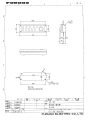
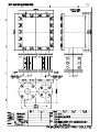
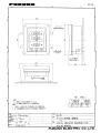
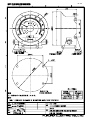
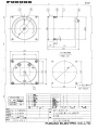
List of Outline Drawings
Name
DS-300 Display/Display Unit
DS-301 Display/Operation Panel
DS-310 Processor Unit
DS-320 Transceiver Unit
DS-325 Transceiver Unit
DS-330 Transducer
DS-330/331 Hull Unit
DS-335 Seachest (with Gate Valve)
DS-360 Junction Box
DS-370 Distribution Box
DS-340 Rate-of-turn Gyro
DS-350 Digital Indicator
DS-351 Digital Indicator (Bulkhead mount)
DS-351 Digital Indicator (Flush mount)
DS-359 Remote Box (Bulkhead mount)
DS-359 Remote Box (Flush mount)
DS-381 Analog Indicator (Flush mount)
DS-382 Analog Indicator (Bulkhead mount)
MF-22A-1 Analog Indicator (Flush mount)
MF-22A-2 Analog Indicator (Bulkhead mount)
MF-22A-3 Analog Indicator (Flush mount)
MF-22A-4 Analog Indicator (Flush mount)
MF-22A-5 Analog Indicator
MF-22A-6 Analog Indicator (Flush mount)
MF-22A-7 Analog Indicator (Flush mount)
MF-22A-8 Analog Indicator (Bulkhead mount)
DS-389 Range Switch Box
MF-22T-1 Distance Indicator (Flush mount)
MF-22T-2 Distance Indicator (Bulkhead mount)
MF-22T-3 Distance Indicator (Tabletop mount)
Main Display Cabinet (70°)
Main Display Cabinet (45°)
D-1
Page
D-2
D-3
D-4
D-5
D-6
D-7
D-8
D-9
D-10
D-11
D-12
D-13
D-14
D-15
D-16
D-17
D-18
D-19
D-20
D-21
D-22
D-23
D-24
D-25
D-26
D-27
D-28
D-29
D-30
D-31
D-32
D-33
D-2
Sep.29'05
D-5
Y. Hatai
D-6
D-8
23/Oct/08 R.Esumi
D-9
Y. Hatai
D−10
Feb.12'04
H.HAYASHI
D-13
Feb.22'05
D−17
Feb.12’04
H.HAYASHI
D-18
Jan.07'06
D-19
Jan.07'06
D-28
May 20 '04
D-29
D-30
D-31
Sep.29'05
D-32 D-34
D-33 D - 35
TB1
CA1-H 17
CA1-C 18
CA1-G 19
RE1-H 33
RE1-C 34
RE1-G 35
CA2-H 20
CA2-C 21
CA2-G 22
RE2-H 36
RE2-C 37
RE2-G 38
A
CA3-H
CA3-C
CA3-G
RE3-H
RE3-C
RE3-G
KP-H
KP-C
アカ 6 RED6
クロ 6 BLK6
P
アカ 7 RED7
クロ 7 BLK7
P
EG-H 28
EG-C 29
アカ 8 RED8
クロ 8 BLK8
P
アオ BLU
ハイ GRY
キ YEL
シロ WHT
アカ RED
クロ BLK
ミドリ GRN
P
42
43
46
47
48
アカ 9 RED9
クロ 9 BLK9
P
アカ10 RED10
クロ10 BLK10
P
アカ11 RED11
クロ11 BLK11
P
アカ12 RED12
クロ12 BLK12
P
TS2
TS1
TD3
TD1
TB1
TD2
アカ RED
クロ BLK
アカ RED
II
P
P
W=50
1
2
3
4
5
6
7
8
9
10
11
12
13
14
15
16
FEP-5P,30/40/50m,φ18.7 (c)
アカ RED
クロ BLK
クロ BLK
I
アカ 3 RED3
クロ 3 BLK3
アカ 5 RED5
クロ 5 BLK5
TX-H
TX-C
TX/RX-G
AC100V
AC100V
C
P
アカ 4 RED4
クロ 4 BLK4
W=50
リモート箱
REMOTE BOX
DS-359 1
2
3
4
5
6
*1
MPYCS-7
*1
IV-8sq.
操作箱
OPERATION
PANEL
DS-301
III
送受波器
TRANSDUCER
DS-330
D
W=50
注記
*1)造船所手配。
*2)オプション。
*3)工場で取付済み。
*4)クランプで接地すること。
NOTE
*1. SHIPYARD SUPPLY.
*2. OPTION.
*3. FITTED AT FACTORY.
*4. GROUND THRU CABLE CLAMP.
1
2
3
4
5
6
7
8
9
10
11
12
P
23
24
25
39
40
41
26
27
RX-H 44
RX-C 45
B
接続箱 DS-360
JUNCTION BOX
アカ 2 RED2
クロ 2 BLK2
EV-S40/0.08x15C,0.8m
送受信部
TRANSCEIVER UNIT
DS-320
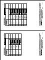
(a)+(b)+(c)≦400m
TTYCY-19S (a) *1
アカ 1 RED1
クロ 1 BLK1
4
3
演算制御部 PROCESSOR UNIT
DS-310
TTYCY-19S (b)
アカ 1 RED1
クロ 1 BLK1
P
アカ 3 RED3
クロ 3 BLK3
P
アカ 4 RED4
クロ 4 BLK4
P
13
14
15
16
17
18
19
20
21
22
23
24
アカ 5 RED5
クロ 5 BLK5
P
アカ 6 RED6
クロ 6 BLK6
P
アカ 7 RED7
クロ 7 BLK7
P
アカ 8 RED8
クロ 8 BLK8
P
25
26
27
28
29
30
31
32
33
34
35
36
アカ 9 RED9
クロ 9 BLK9
P
アカ10 RED10
クロ10 BLK10
P
アカ11 RED11
クロ11 BLK11
P
アカ12 RED12
クロ12 BLK12
P
主指示器
DS-300
MAIN DISPLAY J34
RXD-H A
J31
RXD-C B
XA
TXD-H C
XB
TXD-C D
YA
YB
EST-H E
SWD
EST-C F
SWCK
ECH-H H
SWREQ ECH-C J
LEDD
EDE-H K
LEDC
EDE-C L
ILM
REMO-H M
+5V
REMO-C N
+5V
BF0V P
0V
BF0V R
0V
TB1
0V
AC100V 1
AC100V 2
GND 3
100/110/115/120VAC
200/220/230/240VAC
1φ,50/60Hz
P
アカ 2 RED2
クロ 2 BLK2
デジタル指示器(II)
DIGITAL IND. DS-351
11 EXDM-H
TB1
12 EXDM-C AC100V 1
13 MODE AC100V 2
14 DIM
GND 3
15 KTMS
RXD-H 5
16 GND
RXD-C 6
A
B
C
D
E
F
H
J
K
L
M
N
P
R
S
*1
TB2
1 B1H+
2 B1H3 0VLG1
4 B1L+
5 B1L6 0VLG2
7 B2H+
8 B2H9 0VLG3
10 B2L+
11 B2L12 0VLG4
TB4
7 B3H+
8 B3H9 0VLG5
10 B3L+
11 B3L12 0VLG6
1 BFKP-H
2 BFKP-C
3 BF0V
4 BFEG-H
5 BFEG-C
6 BF0V
TB3
7 TXTJ-H
8 TXTJ-C
9 BF0V
10 TXRJ-H
11 TXRJ-C
12 BF0V
TB4
1 AC105V
2 AC105V
3 GND
*1
TTYC-4S
P
P
TB5
1 SBD1-H
2 SBD1-C
3 BF0V
TB6
GYROD-H
GYROD-C
FG
GYROC-H
GYROC-C
FG
TB7
SBD2-H
SBD2-C
FGA
AC12V-H
AC12V-C
TB9
SBD3-H
SBD3-C
FGA
AC12V-H
AC12V-C
*1
DPYC-1.5
*1
DPYC-2.5
A
B
C
D
E
F
H
J
K
L
M
N
P
R
1
2
1
2
J1
TXD-H
TXD-C
RXD-H
RXD-C
EST-H
EST-C
ECH-H
ECH-C
EDE-H
EDE-C
REMO-H
REMO-C
BF0V
BF0V
TB3
AC100V
AC100V
TB1
AC
AC
ADコンバータ
A-D CONVERTER
AD-100
J6-12
1 DATA-H
2 DATA-C
3 SHIFT-H
4 SHIFT-C
5 FG
*1
TTYC-4S
P
P
*1
TTYC-4S,MAX.50m
P
1
2
7
8
9
P
*1
TTYC-4S,MAX.50m
P
1
2
7
8
9
P
*1
TTYCS-1
TB8
DSKP-H 1
DSKP-C 2
FG 3
RATET-H 4
RATET-C 5
FG 6
RATER-H 7
RATER-C 8
FG 9
DC12V-H 11
DC12V-C 12
FG 10
TB10
DIST-H 1
DIST-C 2
BF0V 3
LG400-H 4
LG400-C 5
BF0V 6
LOGARM-H 7
LOGARM-C 8
BF0V 9
FGB 10
DC12FH 11
DC12FL 12
J4
S1
S2
S3
J5
R2
R1
FG
*1
MPYC-7
1
2
3
CO-0.2x5P
TB1
RXD-H
RXD-C
FG
AC12V-H
AC12V-C
デジタル
指示器(I)
DIGITAL
INDICATOR
DS-350
7
8
9
1
2
TB1
RXD-H
RXD-C
FG
AC12V-H
AC12V-C
デジタル
指示器(I)
DIGITAL
INDICATOR
DS-350
5
4
7
6
3
2
1
P
P
*1
IV-8sq.
*1
IV-8sq.
J3
TXD-H
TXD-C
RXD-H
RXD-C
+12V
0V
FG
レートジャイロ
RATE-OF-TURN
GYRO
DS-340
TB1
AC 1
AC 2
NC 3
*1
DPYC-1.5
100/110/115/120
220/230/240VAC
1φ,60Hz
*1
IV-8sq.
*1
TTYC-4S
P
1
2
3
4
5
6
7
8
9
10
P
P
分配箱
TB1
DISTRIBUTION BOX
RXD-H
DS-370
RXD-C
LG400-H
DSPOUT-H 1
LG400-C
DSPOUT-C 2
FG 3
LOGARM-H
RNGSW1-H 4
LOGARM-C
RNGSW1-C 5
FG0V
PDC12V-H
PDC12V-C
66P3340
TB1
1 AC-H
2 AC-C
P
DPYC-1.5 *1
*1
TTYC-4S
P
P
レンジ切換器
RANGE SWITCH
DS-389
1 SM+
2 SM- *2
3 AS
4 DV
1
2
3
4
10
TTYCS-1 *1
TTYCS-1 *1
TTYCS-1 *1
TTYCS-1 *1
*1
TTYCS-1
5
6
P
KP入力
KP INPUT
DPYC-1.5 *1
KP入力
KP INPUT
DPYC-1.5 *1
アナログ指示器
ANALOG IND.
MF-22A
*2
FL-200S
*1
SL-200
+
L DPYC-1.5
V
LOG信号(200P/NM)
LOG SIGNAL
*2 調光器
DIMMER
L MF-22L
V
U
*1
TTYCS-1
*1
DPYC-1.5
レーダー/ARPA
RADAR/ARPA
航法装置
NAVIGATOR
レーダー
RADAR
深度表示器
DEPTH INDICATOR
P
端子台箱
TERMINAL BOX 1
2
DS-802
3
4
5
6
7
8
*1
IV-2sq.
U
L
MJ-A7SPF0019,2m
シロ WHT
P
アオ BLU
キ YEL
P
ミドリ GRN
アカ RED
クロ BLK
1A
MJ-A6SPF0013,2m
シロ WHT
クロ BLK
*1
DPYC-1.5 100-120/
200-230VAC
1φ,50/60Hz
調光器
DIMMER
MF-22L
J1
航程計
TD-A DISTANCE
TD-B INDICATOR
RD-A DS-840
RD-B
24V-P
0V
FG
J2
1 DIM
2 GND
1
2
3
4
5
6
7
6
*1
IV-2sq.
アナログ指示器
ANALOG
INDICATOR
100-120/
200-240VAC
調光器
DIMMER MF-22L
L
V
U
3kΩ/25W
DARK
BRIGHT
3kΩ/25W
(for 200-240V)
MF-22L詳細 DETAIL FOR MF-22L
W=50
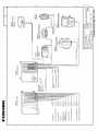
DRAWN
28/Apr/09
CHECKED
28/Apr/09
APPROVED
T.YAMASAKI
T.TAKENO
TITLE
DS-30
名称
ドップラソナー
相互結線図
NAME
DOPPLER SONAR
INTERCONNECTION DIAGRAM
18/Jun/09 R.Esumi
CO-0.2x2P: CO-SPEVV-SB-C 0.2x2P,φ10.5
CO-0.2x5P: CO-SPEVV-SB-C 0.2x5P,φ13.5
CO-0.2x10P: CO-SPEVV-SB-C 0.2x10P,φ16
DPYC-1.5 *1
66P3342D
W=50
1
2
3
4
10
EXKP1-H 1
EXKP1-C 2
FG 3
EXKP2-H 4
EXKP2-C 5
FG 6
TB12
LG2S1-H 1
LG2S1-C 2
FG 3
LG2S2-H 4
LG2S2-C 5
FG 6
LG2S3-H 7
LG2S3-C 8
FG 9
LG2S4-H 10
LG2S4-C 11
FG 12
TB14
LG2S5-H 1
LG2S5-C 2
FG 3
LG2S6-H 4
LG2S6-C 5
FG 6
LG2S7-H 7
LG2S7-C 8
FG 9
LG2S8-H 10
LG2S8-C 11
FG 12
66P3318
*1
IV-8sq.
24VDC
J2
TXD-H
TXD-C
RXD-H
RXD-C
FG
J3
TXD-H
TXD-C
RXD-H
RXD-C
FG
演算制御部
PROCESSOR UNIT
DS-310
TB3
ジャイロコンパス
GYROCOMPASS
1
2
3
7
8
9
1
2
S-1
6
KP出力
KP OUTPUT
P
TB1
AC 3
AC 4
66P3318
CO-0.2x10P
1
2
3
4
5
6
5
*1
DPYC-1.5
2
IEC61162(NMEA0183)
1
SCALE
MASS
kg
DWG No.
C7236-C01- K
1
2
演算制御部
PROCESSOR UNIT
DS-310
A
IEC61162-1
*1
TTYCS-1
*1
TTYCS-1
P
P
*1
TTYCS-1
*1
TTYCS-1
P
P
AUX
B
C
*1
MPYC-19
1
2
3
4
10
1
2
3
4
10
2
3
7
9
10
11
18
25
J2
TXD-H
TXD-C
RXD-H
RXD-C
FG
J3
TXD-H
TXD-C
RXD-H
RXD-C
FG
J4/J5
TRS
RRS
DURS
TH
TC
RH
RC
0VHC
TB3
EXKP1-H 1
EXKP1-C 2
FG 3
EXKP2-H 4
EXKP2-C 5
FG 6
TB10
TXD-H 1
TXD-C 2
FG 3
LOG400T-H 4
LOG400T-C 5
FG 6
ALARM-H 7
ALARM-C 8
FG 9
FG 10
12V+ 11
GND 12
TB11
PROP-H 1
PROP-C 2
FG 3
PITCH-H 4
PITCH-C 5
FG 6
ROLL-H 7
ROLL-C 8
FG 9
FG 10
12V+ 11
GND 12
TB12/14
200P-H 1
200P-C 2
FG 3
200P-H 4
200P-C 5
FG 6
200P-H 7
200P-C 8
FG 9
200P-H 10
200P-C 11
FG 12
TB13
WIND_DIR-H 1
WIND_DIR-C 2
FG 3
WIND_SPD-H 4
WIND_SPD-C 5
FG 6
RUDDER-H 7
RUDDER-C 8
FG 9
LOGSEL-H 10
LOGSEL-C 11
FG 12
66P3318
TB1
AC100V 3
AC100V 4
4
3
*1
TTYCS-1
EXTERNAL EQUIPMENT
*1
TTYCS-1
EXTERNAL EQUIPMENT
OCP 66P3340
*1
TTYC-4S
P
1
2
3
4
5
6
7
8
9
10
11
12
P
P
P
*1
TTYCS-1
*1
TTYCS-1
*1
TTYCS-1
*1
TTYCS-1
分配箱
DISTRIBUTION
BOX
DS-370
RXD-H
RXD-C
LG400T-H
LG400T-C
ALARM-H
ALARM-C
0V
12V+
GND
TACHOMETER
OAV 66P3342V
ANALOGV-H
ANALOGV-C
GND
STATUS-H
STATUS-C
GND
1
2
3
7
8
9
OAC 66P3342C
ANALOGC-H
ANALOGC-C
GND
STATUS-H
STATUS-C
GND
1
2
3
7
8
9
*1
TTYCS-1
1
2
3
4
5
SHIP'S SPEED STATUS
*1
TTYCS-1
SHIP'S SPEED CURRENT
*1
TTYCS-1
SHIP'S SPEED STATUS
アナログ指示器
ANALOG IND.
*1
TTYC-4S
P
P
S-2
6
SHIP'S SPEED VOLTAGE
*1
TTYCS-1
OAD 66P3342D
ANALOGDSP-H
ANALOGDSP-C
GND
RANGE-H
RANGE-C
5
レンジ切換器
RANGE SWITCH
1 SM+ DS-389
*2
2 SM3 AS
5
4 DV
6
*1
TTYCS-1
*1
TTYCS-1
DS-381/382
*2
+
L
V
MF-22A *2
FL-200S
SL-200
+
L
V
*1
DPYC-1.5
*2 調光器
DIMMER
MF-22L
L
V
U
*1
DPYC-1.5
100-115/
200-240VAC
1φ,50/60Hz
CLINOMETER (PITCH)
OLG 66P3346L
LG200R-H
LG200R-C
LG200R-H
LG200R-C
STATUS-H
STATUS-C
GND
LG400T-H
LG400T-C
GND
AC12V-H
AC12V-C
CLINOMETER (ROLL)
DISTANCE SIGNAL
*1
TTYCS-1
*1
TTYCS-1
1
2
3
4
5
6
7
8
9
10
11
12
TB3
AC100V-H 10
AC100V-C 11
GND 12
*1
TTYCS-1
*1
TTYCS-1
*1
TTYCS-1
*1
TTYC-4S
P
OTX 66P3346T
*1
TTYCS-1
TXD-H
TXD-C
LG400T-H
LG400T-C
ALARM-H
ALARM-C
GND
DC12V-H
DC12V-C
GND
AC12V
AC12V
*1
TTYCS-1
*1
TTYCS-1
*1
TTYCS-1
*1
DPYC-1.5
1
2
3
4
5
6
7
8
9
10
11
12
P
SHIP'S SPEED STATUS
SHIP'S SPEED STATUS
デジタル指示器 *2
DIGITAL INDICATOR
TB1 DS-351 TB1
1
2
3
5
6
AC100V-H
AC100V-C
GND
RXD-H
RXD-C
11
12
13
14
15
16
MPYCS-7
1
2
3
4
5
6
リモート箱
REMOTE BOX
DS-359 *2
*1
IV-2sq.
TB1
1 AC-H
2 AC-C
3 FG
アナログ指示器
ANALOG
INDICATOR
W=50
100-120/
200-240VAC
D
調光器
DIMMER MF-22L
L
V
U
DARK
3kΩ/25W
BRIGHT
3kΩ/25W
(for 200-240V)
MF-22L詳細 DETAIL FOR MF-22L
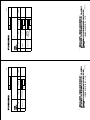
注記
*1)造船所手配。
*2)オプション。
*3)分配箱には任意の組み合わせで最大7枚の基板を組み込み可能。
*4)2台の分配箱を使用するときは、1台はOTX基板を利用すること。
NOTE
*1. SHIPYARD SUPPLY.
*2. OPTION.
*3. DISTRIBUTION BOX CAN INCORPORATE SEVEN BOARD IN ANY COMBINATION.
*4. WHEN TWO DISTRIBUTION BOXES ARE USED, CONNECT ONE DISTRIBUTION BOX TO "OTX" BOARD.
DRAWN
28/Apr/09
CHECKED
28/Apr/09
APPROVED
T.YAMASAKI
T.TAKENO
TITLE
DS-30 (DS-370)
名称
ドップラソナー(分配箱)
相互結線図
NAME
DOPPLER SONAR (DISTRIBUTION BOX)
INTERCONNECTION DIAGRAM
18/Jun/09 R.Esumi
CO-0.2x2P: CO-SPEVV-SB-C 0.2x2P,φ10.5
CO-0.2x5P: CO-SPEVV-SB-C 0.2x5P,φ13.5
CO-0.2x10P: CO-SPEVV-SB-C 0.2x10P,φ16
SCALE
MASS
kg
DWG No.
C7236-C02- K
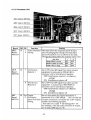
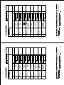
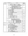
Board
Switch Setting
Function
MIF Board
#1
#2
OFF
OFF
OFF
ON
ON
OFF
ON
OFF
ON
OFF
Ship’s speed for distance run pulse selection
Speed over-the-ground & through-water & speed
fed from nav sensor
Speed over-the-ground & through-water
Speed through-water
Type of ship’s speed for distance run pulse: Vector
Ditto
: Fore-aft
Bearing data output: True course
Ditto
: Heading
Bearing data output at low Ship’s speed: True course
Ditto
:Heading
(Since ship’s course data fluctuates by rolling and
pitching when ship’s speed is extremely low,
heading data is output instead of course. )
Distance signal alarm
Contact: ON = No alarm
Fore-aft status
Contact: ON = Aft (note 1)
CIF/NMEA 1 option data: Off
Ditto
: On
(Note 2.)
CIF/NMEA 2 option data: Off
Ditto
: On
(Note 2.)
Engine revolution full scale setting.
Rate-of turn gyro data averaging time: 10 mses
: 20mses
Ditto
: 40mses
Ditto
: 80mses
Ditto
: 160mses
Ditto
: 230mses
Ditto
: 640mses
Ditto
: 1280mses
Ditto
#3
#4
S4
#5
#6
#7
#8
S5
S6
0 to F
0
1
2
3
4
5
6
7 to F
ON
OFF
ON
OFF
ON
OFF
ON
Factory
setting
○
○
○
○
○
◎
◎
◎
Note 1: Prior to setting #6 to “ON”, set #3 to “ON”.
Note 2: DRU (Dual Doppler Auxiliary Data) and VWT (True Wind Speed and Angle) are outputted.
AP-6