1
C120-E360-06EN
SPARC® Enterprise
M3000/M4000/M5000/M8000/M9000 Servers
RCI User’s Guide
Copyright 2007-2008 FUJITSU LIMITED, 1-1, Kamikodanaka 4-chome, Nakahara-ku, Kawasaki-shi, Kanagawa-ken 211-8588, Japan.
All rights reserved.
Sun Microsystems, Inc. provided technical input and review on portions of this material.
Sun Microsystems, Inc. and Fujitsu Limited each own or control intellectual property rights relating to products and technology described
in this document, and such products, technology and this document are protected by copyright laws, patents and other intellectual property
laws and international treaties. The intellectual property rights of Sun Microsystems, Inc. and Fujitsu Limited in such products,
technology and this document include, without limitation, one or more of the United States patents listed at http://www.sun.com/patents
and one or more additional patents or patent applications in the United States or other countries.
This document and the product and technology to which it pertains are distributed under licenses restricting their use, copying,
distribution, and decompilation. No part of such product or technology, or of this document, may be reproduced in any form by any means
without prior written authorization of Fujitsu Limited and Sun Microsystems, Inc., and their applicable licensors, if any. The furnishing of
this document to you does not give you any rights or licenses, express or implied, with respect to the product or technology to which it
pertains, and this document does not contain or represent any commitment of any kind on the part of Fujitsu Limited or Sun
Microsystems, Inc., or any affiliate of either of them.
This document and the product and technology described in this document may incorporate third-party intellectual property copyrighted
by and/or licensed from suppliers to Fujitsu Limited and/or Sun Microsystems, Inc., including software and font technology.
Per the terms of the GPL or LGPL, a copy of the source code governed by the GPL or LGPL, as applicable, is available upon request by
the End User. Please contact Fujitsu Limited or Sun Microsystems, Inc
This distribution may include materials developed by third parties.
Parts of the product may be derived from Berkeley BSD systems, licensed from the University of California. UNIX is a registered
trademark in the U.S. and in other countries, exclusively licensed through X/Open Company, Ltd.
Sun, Sun Microsystems, the Sun logo, Java, Netra, Solaris, Sun Ray, Answerbook2, docs.sun.com, OpenBoot, and Sun Fire are
trademarks or registered trademarks of Sun Microsystems, Inc., or its subsidiaries, in the U.S. and other countries.
Fujitsu and the Fujitsu logo are registered trademarks of Fujitsu Limited.
All SPARC trademarks are used under license and are registered trademarks of SPARC International, Inc. in the U.S. and other countries.
Products bearing SPARC trademarks are based upon architecture developed by Sun Microsystems, Inc.
SPARC64 is a trademark of SPARC International, Inc., used under license by Fujitsu Microelectronics, Inc. and Fujitsu Limited.
The OPEN LOOK and Sun™ Graphical User Interface was developed by Sun Microsystems, Inc. for its users and licensees. Sun
acknowledges the pioneering efforts of Xerox in researching and developing the concept of visual or graphical user interfaces for the
computer industry. Sun holds a non-exclusive license from Xerox to the Xerox Graphical User Interface, which license also covers Sun’s
licensees who implement OPEN LOOK GUIs and otherwise comply with Sun’s written license agreements.
United States Government Rights - Commercial use. U.S. Government users are subject to the standard government user license
agreements of Sun Microsystems, Inc. and Fujitsu Limited and the applicable provisions of the FAR and its supplements.
Disclaimer: The only warranties granted by Fujitsu Limited, Sun Microsystems, Inc. or any affiliate of either of them in connection with
this document or any product or technology described herein are those expressly set forth in the license agreement pursuant to which the
product or technology is provided. EXCEPT AS EXPRESSLY SET FORTH IN SUCH AGREEMENT, FUJITSU LIMITED, SUN
MICROSYSTEMS, INC. AND THEIR AFFILIATES MAKE NO REPRESENTATIONS OR WARRANTIES OF ANY KIND
(EXPRESS OR IMPLIED) REGARDING SUCH PRODUCT OR TECHNOLOGY OR THIS DOCUMENT, WHICH ARE ALL
PROVIDED AS IS, AND ALL EXPRESS OR IMPLIED CONDITIONS, REPRESENTATIONS AND WARRANTIES, INCLUDING
WITHOUT LIMITATION ANY IMPLIED WARRANTY OF MERCHANTABILITY, FITNESS FOR A PARTICULAR PURPOSE OR
NON-INFRINGEMENT, ARE DISCLAIMED, EXCEPT TO THE EXTENT THAT SUCH DISCLAIMERS ARE HELD TO BE
LEGALLY INVALID. Unless otherwise expressly set forth in such agreement, to the extent allowed by applicable law, in no event shall
Fujitsu Limited, Sun Microsystems, Inc. or any of their affiliates have any liability to any third party under any legal theory for any loss of
revenues or profits, loss of use or data, or business interruptions, or for any indirect, special, incidental or consequential damages, even if
advised of the possibility of such damages.
DOCUMENTATION IS PROVIDED “AS IS” AND ALL EXPRESS OR IMPLIED CONDITIONS, REPRESENTATIONS AND
WARRANTIES, INCLUDING ANY IMPLIED WARRANTY OF MERCHANTABILITY, FITNESS FOR A PARTICULAR PURPOSE
OR NON-INFRINGEMENT, ARE DISCLAIMED, EXCEPT TO THE EXTENT THAT SUCH DISCLAIMERS ARE HELD TO BE
LEGALLY INVALID.
Please
Recycle
C120-E360-06EN
Copyright 2007-2008 FUJITSU LIMITED, 1-1, Kamikodanaka 4-chome, Nakahara-ku, Kawasaki-shi, Kanagawa-ken 211-8588, Japon.
Tous droits réservés.
Entrée et revue tecnical fournies par Sun Microsystems, Incl sur des parties de ce matériel.
Sun Microsystems, Inc. et Fujitsu Limited détiennent et contrôlent toutes deux des droits de propriété intellectuelle relatifs aux produits et
technologies décrits dans ce document. De même, ces produits, technologies et ce document sont protégés par des lois sur le copyright,
des brevets, d’autres lois sur la propriété intellectuelle et des traités internationaux. Les droits de propriété intellectuelle de Sun
Microsystems, Inc. et Fujitsu Limited concernant ces produits, ces technologies et ce document comprennent, sans que cette liste soit
exhaustive, un ou plusieurs des brevets déposés aux États-Unis et indiqués à l’adresse http://www.sun.com/patents de même qu’un ou
plusieurs brevets ou applications brevetées supplémentaires aux États-Unis et dans d’autres pays.
Ce document, le produit et les technologies afférents sont exclusivement distribués avec des licences qui en restreignent l’utilisation, la
copie, la distribution et la décompilation. Aucune partie de ce produit, de ces technologies ou de ce document ne peut être reproduite sous
quelque forme que ce soit, par quelque moyen que ce soit, sans l’autorisation écrite préalable de Fujitsu Limited et de Sun Microsystems,
Inc., et de leurs éventuels bailleurs de licence. Ce document, bien qu’il vous ait été fourni, ne vous confère aucun droit et aucune licence,
expresses ou tacites, concernant le produit ou la technologie auxquels il se rapporte. Par ailleurs, il ne contient ni ne représente aucun
engagement, de quelque type que ce soit, de la part de Fujitsu Limited ou de Sun Microsystems, Inc., ou des sociétés affiliées.
Ce document, et le produit et les technologies qu’il décrit, peuvent inclure des droits de propriété intellectuelle de parties tierces protégés
par copyright et/ou cédés sous licence par des fournisseurs à Fujitsu Limited et/ou Sun Microsystems, Inc., y compris des logiciels et des
technologies relatives aux polices de caractères.
Par limites du GPL ou du LGPL, une copie du code source régi par le GPL ou LGPL, comme applicable, est sur demande vers la fin
utilsateur disponible; veuillez contacter Fujitsu Limted ou Sun Microsystems, Inc.
Cette distribution peut comprendre des composants développés par des tierces parties.
Des parties de ce produit pourront être dérivées des systèmes Berkeley BSD licenciés par l’Université de Californie. UNIX est une
marque déposée aux Etats-Unis et dans d’autres pays et licenciée exclusivement par X/Open Company, Ltd.
Sun, Sun Microsystems, le logo Sun, Java, Netra, Solaris, Sun Ray, Answerbook2, docs.sun.com, OpenBoot, et Sun Fire sont des marques
de fabrique ou des marques déposées de Sun Microsystems, Inc., ou ses filiales, aux Etats-Unis et dans d’autres pays.
Fujitsu et le logo Fujitsu sont des marques déposées de Fujitsu Limited.
Toutes les marques SPARC sont utilisées sous licence et sont des marques de fabrique ou des marques déposées de SPARC International,
Inc. aux Etats-Unis et dans d’autres pays. Les produits portant les marques SPARC sont basés sur une architecture développée par Sun
Microsystems, Inc.
SPARC64 est une marques déposée de SPARC International, Inc., utilisée sous le permis par Fujitsu Microelectronics, Inc. et Fujitsu
Limited.
L’interface d’utilisation graphique OPEN LOOK et Sun™ a été développée par Sun Microsystems, Inc. pour ses utilisateurs et licenciés.
Sun reconnaît les efforts de pionniers de Xerox pour la recherche et le développement du concept des interfaces d’utilisation visuelle ou
graphique pour l’industrie de l’informatique. Sun détient une license non exclusive de Xerox sur l’interface d’utilisation graphique Xerox,
cette licence couvrant également les licenciés de Sun qui mettent en place l’interface d’utilisation graphique OPEN LOOK et qui, en
outre, se conforment aux licences écrites de Sun.
Droits du gouvernement américain - logiciel commercial. Les utilisateurs du gouvernement américain sont soumis aux contrats de licence
standard de Sun Microsystems, Inc. et de Fujitsu Limited ainsi qu’aux clauses applicables stipulées dans le FAR et ses suppléments.
Avis de non-responsabilité: les seules garanties octroyées par Fujitsu Limited, Sun Microsystems, Inc. ou toute société affiliée de l’une ou
l’autre entité en rapport avec ce document ou tout produit ou toute technologie décrit(e) dans les présentes correspondent aux garanties
expressément stipulées dans le contrat de licence régissant le produit ou la technologie fourni(e). SAUF MENTION CONTRAIRE
EXPRESSÉMENT STIPULÉE DANS CE CONTRAT, FUJITSU LIMITED, SUN MICROSYSTEMS, INC. ET LES SOCIÉTÉS
AFFILIÉES REJETTENT TOUTE REPRÉSENTATION OU TOUTE GARANTIE, QUELLE QU’EN SOIT LA NATURE (EXPRESSE
OU IMPLICITE) CONCERNANT CE PRODUIT, CETTE TECHNOLOGIE OU CE DOCUMENT, LESQUELS SONT FOURNIS EN
L’ÉTAT. EN OUTRE, TOUTES LES CONDITIONS, REPRÉSENTATIONS ET GARANTIES EXPRESSES OU TACITES, Y
COMPRIS NOTAMMENT TOUTE GARANTIE IMPLICITE RELATIVE À LA QUALITÉ MARCHANDE, À L’APTITUDE À UNE
UTILISATION PARTICULIÈRE OU À L’ABSENCE DE CONTREFAÇON, SONT EXCLUES, DANS LA MESURE AUTORISÉE
PAR LA LOI APPLICABLE. Sauf mention contraire expressément stipulée dans ce contrat, dans la mesure autorisée par la loi applicable,
en aucun cas Fujitsu Limited, Sun Microsystems, Inc. ou l’une de leurs filiales ne sauraient être tenues responsables envers une
quelconque partie tierce, sous quelque théorie juridique que ce soit, de tout manque à gagner ou de perte de profit, de problèmes
d’utilisation ou de perte de données, ou d’interruptions d’activités, ou de tout dommage indirect, spécial, secondaire ou consécutif, même
si ces entités ont été préalablement informées d’une telle éventualité.
LA DOCUMENTATION EST FOURNIE “EN L’ETAT” ET TOUTES AUTRES CONDITIONS, DECLARATIONS ET GARANTIES
EXPRESSES OU TACITES SONT FORMELLEMENT EXCLUES, DANS LA MESURE AUTORISEE PAR LA LOI APPLICABLE,
Y COMPRIS NOTAMMENT TOUTE GARANTIE IMPLICITE RELATIVE A LA QUALITE MARCHANDE, A L’APTITUDE A
UNE UTILISATION PARTICULIERE OU A L’ABSENCE DE CONTREFACON.
C120-E360-06EN
Preface
1
This manual describes the Remote Cabinet Interface (RCI) function on SPARC®
Enterprise series servers. This manual is intended for users, specifically system
management/maintenance administrators. However, when carrying out actual
operations, authorized service personnels do it.
Be sure to also read the SPARC Enterprise M3000/M4000/M5000/M8000/M9000
Servers XSCF User’s Guide and other manuals referenced in this manual.
This section includes:
z
z
z
z
z
z
z
z
z
z
Audience
Glossary
Structure and Contents of this Manual
SPARC Enterprise Mx000 Servers Documentation
Abbreviated References to Other Documents
Models
Text Conventions
Prompt Notations
Syntax of the Command-Line Interface (CLI)
Fujitsu Welcomes Your Comments
Audience
This manual is intended for users, specifically SPARC Enterprise system
management/maintenance administrators. Moreover, the system administrator is
required to have the following knowledge:
- SolarisTM Operating System (Solaris OS) and Unix command
- SPARC Enterprise system and basic knowledge of XSCF
Glossary
For the terms used in the "SPARC Enterprise Mx000 Servers Documentation", refer
to the SPARC Enterprise M3000/M4000/M5000/M8000/M9000 Servers Glossary.
Structure and Contents of this Manual
This manual is organized as described below:
C120-E360-06EN
i
Preface
CHAPTER 1 RCI Overview
This chapter gives an overview of the Remote Cabinet Interface (RCI).
CHAPTER 2 Setup of the RCI for Operation
This chapter describes setup information for use of the RCI.
CHAPTER 3 Command Reference
This chapter describes the RCI command.
CHAPTER 4 Error Status
This chapter describes the error status codes.
ii
C120-E360-06EN
Preface
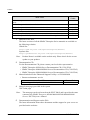
SPARC Enterprise Mx000 Servers Documentation
The manuals listed below are provided for reference.
Book Titles
SPARC Enterprise M3000 Server Site Planning Guide
SPARC Enterprise M4000/M5000 Servers Site Planning Guide
SPARC Enterprise M8000/M9000 Servers Site Planning Guide
SPARC Enterprise Equipment Rack Mounting Guide
SPARC Enterprise M3000 Server Getting Started Guide
SPARC Enterprise M4000/M5000 Servers Getting Started Guide
SPARC Enterprise M8000/M9000 Servers Getting Started Guide
SPARC Enterprise M3000 Server Overview Guide
SPARC Enterprise M4000/M5000 Servers Overview Guide
SPARC Enterprise M8000/M9000 Servers Overview Guide
Important Safety Information for Hardware Systems
SPARC Enterprise M3000 Server Safety and Compliance Guide
SPARC Enterprise M4000/M5000 Servers Safety and Compliance Guide
SPARC Enterprise M8000/M9000 Servers Safety and Compliance Guide
External I/O Expansion Unit Safety and Compliance Guide
SPARC Enterprise M4000 Server Unpacking Guide
SPARC Enterprise M5000 Server Unpacking Guide
SPARC Enterprise M8000/M9000 Servers Unpacking Guide
SPARC Enterprise M3000 Server Installation Guide
SPARC Enterprise M4000/M5000 Servers Installation Guide
SPARC Enterprise M8000/M9000 Servers Installation Guide
SPARC Enterprise M3000 Server Service Manual
SPARC Enterprise M4000/M5000 Servers Service Manual
SPARC Enterprise M8000/M9000 Servers Service Manual
External I/O Expansion Unit Installation and Service Manual
SPARC Enterprise M3000/M4000/M5000/M8000/M9000 Servers RCI Build
Procedure
SPARC Enterprise M3000/M4000/M5000/M8000/M9000 Servers Administration
Guide
SPARC Enterprise M3000/M4000/M5000/M8000/M9000 Servers XSCF User’s
Guide
SPARC Enterprise M3000/M4000/M5000/M8000/M9000 Servers XSCF
Reference Manual
SPARC Enterprise M4000/M5000/M8000/M9000 Servers Dynamic
Reconfiguration (DR) User’s Guide
SPARC Enterprise M4000/M5000/M8000/M9000 Servers Capacity on Demand
(COD) User’s Guide
C120-E360-06EN
Manual
Codes
C120-H030
C120-H015
C120-H014
C120-H016
C120-E536
C120-E345
C120-E323
C120-E537
C120-E346
C120-E324
C120-E391
C120-E538
C120-E348
C120-E326
C120-E457
C120-E349
C120-E350
C120-E327
C120-E539
C120-E351
C120-E328
C120-E540
C120-E352
C120-E330
C120-E329
C120-E361
C120-E331
C120-E332
C120-E333
C120-E335
C120-E336
iii
Preface
Book Titles
SPARC Enterprise M3000/M4000/M5000/M8000/M9000 Servers RCI User’s
Guide
SPARC Enterprise M3000 Server Product Notes
SPARC Enterprise M4000/M5000 Servers Product Notes
SPARC Enterprise M8000/M9000 Servers Product Notes
External I/O Expansion Unit Product Notes
SPARC Enterprise M3000/M4000/M5000/M8000/M9000 Servers Glossary
SPARC Enterprise/PRIMEQUEST Common Installation Planning Manual
1
Manual
Codes
C120-E360
Go to the Web
Go to the Web
Go to the Web
C120-E456
C120-E514
C120-H007
Manuals on the Web
The latest versions of all the SPARC Enterprise Series manuals are available at
the following websites.
Global Site
http://www.fujitsu.com/sparcenterprise/manual/
Japanese Site
http://primeserver.fujitsu.com/sparcenterprise/manual/
Note:
2
3
Product Notes is available on the website only. Please check for the recent
update on your product.
Documentation CD
For the Documentation CD, please contact your local sales representative.
• SPARC Enterprise M3000 Server Documentation CD (C120-E541)
• SPARC Enterprise M4000/M5000 Servers Documentation CD (C120-E365)
• SPARC Enterprise M8000/M9000 Servers Documentation CD (C120-E364)
Manual included on the Enhanced Support Facility x.x CD-ROM disk
• Remote maintenance service
Book Title
Enhanced Support Facility User's Guide for REMCS
4
Manual (man page) provided in the system
XSCF man page
Note:
5
iv
Manual Code
C112-B067
The man page can be referenced on the XSCF Shell, and it provides the same
content as the SPARC Enterprise M3000/M4000/M5000/M8000/M9000
Servers XSCF Reference Manual.
Documentation and Support on the Web
The latest information about other documents and the support for your server are
provided on the websites.
C120-E360-06EN
Preface
1
Message
Global Site
http://www.fujitsu.com/sparcenterprise/msg/
Japanese Site
http://primeserver.fujitsu.com/sparcenterprise/msg/
2
Firmware program
You can download the latest files of firmware at the following websites.
Global Site
http://www.fujitsu.com/sparcenterprise/firmware/
Japanese Site
http://primeserver.fujitsu.com/sparcenterprise/download/
firmware/
The following files or document are provided.
• Firmware program file (XSCF Control Package (XCP) file)
• XSCF extension MIB definition file
Note:
XSCF Control Package (XCP) : XCP is a package which has the control
programs of hardware that configures a computing system. The XSCF
firmware and the OpenBootTM PROM firmware are included in the XCP
file.
3
Fault Management MIB (SUN-FM-MIB) definition file
http://src.opensolaris.org/source/xref/onnv/onnv-gate/
usr/src/lib/fm/libfmd_snmp/mibs/
6
Solaris Operating System Related Manuals
http://docs.sun.com
7
Provided In firmware program CD (For maintenance service <for FEs>)
• Firmware program file (XSCF Control Package (XCP) file)
• XSCF extension MIB definition file
8
Information on Using the RCI function
The manual does not contain an explanation of the RCI build procedure. For
information on using the RCI function, refer to the SPARC Enterprise M3000/
M4000/M5000/M8000/M9000 Servers RCI Build Procedure available on the
website.
C120-E360-06EN
v
Preface
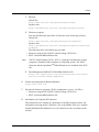
Abbreviated References to Other Documents
In this manual, the following abbreviated titles may be used when referring to a
systems manual. The following table lists the abbreviations used in this manual.
Abbreviated Title
Full Title
Overview Guide
SPARC Enterprise M3000 Server Overview Guide
SPARC Enterprise M4000/M5000 Servers Overview Guide
SPARC Enterprise M8000/M9000 Servers Overview Guide
Service Manual
SPARC Enterprise M3000 Server Service Manual
SPARC Enterprise M4000/M5000 Servers Service Manual
SPARC Enterprise M8000/M9000 Servers Service Manual
Installation Guide
SPARC Enterprise M3000 Server Installation Guide
SPARC Enterprise M4000/M5000 Servers Installation Guide
SPARC Enterprise M8000/M9000 Servers Installation Guide
Administration
SPARC Enterprise M3000/M4000/M5000/M8000/M9000 Servers
Guide
Administration Guide
XSCF User’s Guide SPARC Enterprise M3000/M4000/M5000/M8000/M9000 Servers
XSCF User’s Guide
XSCF Reference
SPARC Enterprise M3000/M4000/M5000/M8000/M9000 Servers
Manual
XSCF Reference Manual
Glossary
SPARC Enterprise M3000/M4000/M5000/M8000/M9000 Servers
Glossary
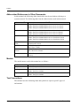
Models
The model names used in this manual are as follows.
Server class
Entry-level
Midrange
High-end
Model name
SPARC Enterprise M3000
SPARC Enterprise M4000
SPARC Enterprise M5000
SPARC Enterprise M8000
SPARC Enterprise M9000
Text Conventions
This manual uses the following fonts and symbols to express specific types of
information.
vi
C120-E360-06EN
Preface
Fonts/symbols
Meaning
AaBbCc123
What you type, when contrasted
with on-screen computer
output.
This font represents the
example of command input in
the frame.
AaBbCc123
The names of commands, files,
and directories; on-screen
computer output.
This font represents the
example of command output in
the frame.
Italic font
Indicates the name of a
reference manual.
""
Indicates names of chapters,
sections, items, buttons, or
menus.
Examples
XSCF> adduser jsmith
XSCF> showuser -p
User Name:
jsmith
Privileges:
useradm
auditadm
See the XSCF Reference Manual.
See Chapter 2, "Setup of the RCI for
Operation."
Prompt Notations
The prompt notations used in this manual are as follows
Shell
XSCF
C shell
C shell super user
Bourne shell and Korn shell
Bourne shell and Korn shell super user
OpenBoot PROM
Prompt Notations
XSCF>
machine-name%
machine-name#
$
#
ok
Syntax of the Command-Line Interface (CLI)
The command syntax is described below.
Command syntax
The command syntax is as follows:
z A variable that requires input of a value must be enclosed in <>.
z An optional element must be enclosed in [ ].
z A group of options for an optional keyword must be enclosed in [ ] and delimited
by |.
z A group of options for a mandatory keyword must be enclosed in {} and delimited
by |.
C120-E360-06EN
vii
z The command syntax is shown in a box.
Example:
XSCF> showuser -a
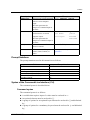
Fujitsu Welcomes Your Comments
If you have any comments or requests regarding this manual, or if you find any
unclear statements in the manual, please state your points specifically on the form at
the following URL.
For Users in U.S.A., Canada, and Mexico:
http://www.computers.us.fujitsu.com/www/
support_servers.shtml?support/servers
For Users in Other Countries:
SPARC Enterprise contact
http://www.fujitsu.com/global/contact/computing/
sparce_index.html
viii
C120-E360-06EN
Contents
Preface . . . . . . . . . . . . . . . . . . . . . . . . . . . . . . . . . . . . . . . . . . . . . i
CHAPTER 1 RCI Overview . . . . . . . . . . . . . . . . . . . . . . . . . . . . . . . . . . . . . . . 1-1
1.1
1.2
1.3
RCI Features . . . . . . . . . . . . . . . . . . . . . . . . . . . . . . . . . . . . . . . . . . . . . . . . .
RCI redundancy (only for the high-end system) . . . . . . . . . . . . . . . . .
RCI Functions. . . . . . . . . . . . . . . . . . . . . . . . . . . . . . . . . . . . . . . . . . . . . . . . .
RCI network status monitoring . . . . . . . . . . . . . . . . . . . . . . . . . . . . . . .
Control of power supply to RCI I/O units . . . . . . . . . . . . . . . . . . . . . . .
Interlocking mechanism for power supply to domains . . . . . . . . . . . . .
Facility control . . . . . . . . . . . . . . . . . . . . . . . . . . . . . . . . . . . . . . . . . . . .
Power-on wait . . . . . . . . . . . . . . . . . . . . . . . . . . . . . . . . . . . . . . . . . . . .
Asynchronous RCI monitoring . . . . . . . . . . . . . . . . . . . . . . . . . . . . . . .
RCI Connection Scheme . . . . . . . . . . . . . . . . . . . . . . . . . . . . . . . . . . . . . . . .
Basic configuration . . . . . . . . . . . . . . . . . . . . . . . . . . . . . . . . . . . . . . . .
Cluster configuration . . . . . . . . . . . . . . . . . . . . . . . . . . . . . . . . . . . . . . .
Duplicated configuration . . . . . . . . . . . . . . . . . . . . . . . . . . . . . . . . . . . .
1-1
1-2
1-2
1-2
1-2
1-2
1-3
1-3
1-3
1-4
1-4
1-5
1-5
CHAPTER 2 Setup of the RCI for Operation . . . . . . . . . . . . . . . . . . . . . . . . . 2-1
2.1
2.2
Overview of RCI Setup . . . . . . . . . . . . . . . . . . . . . . . . . . . . . . . . . . . . . . . . .
RCI Setup for Initial Installation . . . . . . . . . . . . . . . . . . . . . . . . . . . . . . . . . . .
2.2.1 RCI setup flow . . . . . . . . . . . . . . . . . . . . . . . . . . . . . . . . . . . . . . . . . . . .
2.2.2 Confirming RCI initialization . . . . . . . . . . . . . . . . . . . . . . . . . . . . . . . . .
To confirm RCI initialization: . . . . . . . . . . . . . . . . . . . . . . . . . . . . . . . . .
2.2.3 Connecting RCI cables . . . . . . . . . . . . . . . . . . . . . . . . . . . . . . . . . . . . .
2.2.4 Making an RCI address setting . . . . . . . . . . . . . . . . . . . . . . . . . . . . . . .
To specify an RCI address: . . . . . . . . . . . . . . . . . . . . . . . . . . . . . . . . .
To confirm an RCI address: . . . . . . . . . . . . . . . . . . . . . . . . . . . . . . . . .
2.2.5 Making an RCI construction setting . . . . . . . . . . . . . . . . . . . . . . . . . . .
To make an RCI construction setting: . . . . . . . . . . . . . . . . . . . . . . . . .
To confirm an RCI construction setting: . . . . . . . . . . . . . . . . . . . . . . . .
2.3 RCI Setup for Addition of an RCI I/O Unit . . . . . . . . . . . . . . . . . . . . . . . . . . .
2.3.1 RCI setup flow . . . . . . . . . . . . . . . . . . . . . . . . . . . . . . . . . . . . . . . . . . . .
2.3.2 Connecting an RCI cable . . . . . . . . . . . . . . . . . . . . . . . . . . . . . . . . . . .
2.3.3 Making an RCI expansion setting . . . . . . . . . . . . . . . . . . . . . . . . . . . . .
To make an RCI expansion setting: . . . . . . . . . . . . . . . . . . . . . . . . . . .
To confirm an RCI expansion setting: . . . . . . . . . . . . . . . . . . . . . . . . .
2.4 RCI Setup for Addition of an RCI Base Cabinet . . . . . . . . . . . . . . . . . . . . . .
2.4.1 RCI setup flow . . . . . . . . . . . . . . . . . . . . . . . . . . . . . . . . . . . . . . . . . . . .
2.4.2 Confirming RCI initialization . . . . . . . . . . . . . . . . . . . . . . . . . . . . . . . . .
To confirm RCI initialization: . . . . . . . . . . . . . . . . . . . . . . . . . . . . . . . . .
2.4.3 Connecting an RCI cable . . . . . . . . . . . . . . . . . . . . . . . . . . . . . . . . . . .
C120-E360-06EN
2-1
2-2
2-2
2-2
2-2
2-3
2-3
2-3
2-3
2-3
2-4
2-4
2-4
2-4
2-5
2-5
2-5
2-5
2-6
2-6
2-6
2-6
2-6
ix
Contents
2.4.4
Making an RCI address setting . . . . . . . . . . . . . . . . . . . . . . . . . . . . . . .
To specify an RCI address: . . . . . . . . . . . . . . . . . . . . . . . . . . . . . . . . . .
To confirm the specified RCI address: . . . . . . . . . . . . . . . . . . . . . . . . .
2.4.5 Making an RCI expansion setting . . . . . . . . . . . . . . . . . . . . . . . . . . . . .
To make an RCI expansion setting: . . . . . . . . . . . . . . . . . . . . . . . . . . .
To confirm an RCI expansion setting: . . . . . . . . . . . . . . . . . . . . . . . . . .
2.5 RCI Setup for Replacement of an RCI I/O Unit . . . . . . . . . . . . . . . . . . . . . . .
2.5.1 RCI setup flow . . . . . . . . . . . . . . . . . . . . . . . . . . . . . . . . . . . . . . . . . . . .
2.5.2 Confirming an RCI address . . . . . . . . . . . . . . . . . . . . . . . . . . . . . . . . . .
To confirm an RCI address: . . . . . . . . . . . . . . . . . . . . . . . . . . . . . . . . .
To confirm the location of an RCI I/O unit: . . . . . . . . . . . . . . . . . . . . . .
2.5.3 Replacing an RCI I/O Unit . . . . . . . . . . . . . . . . . . . . . . . . . . . . . . . . . . .
2.5.4 Making an RCI replacement setting. . . . . . . . . . . . . . . . . . . . . . . . . . . .
To make an RCI replacement setting: . . . . . . . . . . . . . . . . . . . . . . . . . .
To confirm an RCI replacement setting: . . . . . . . . . . . . . . . . . . . . . . . .
2.6 RCI Setup for Replacement of an RCI Base Cabinet . . . . . . . . . . . . . . . . . .
2.6.1 RCI setup flow . . . . . . . . . . . . . . . . . . . . . . . . . . . . . . . . . . . . . . . . . . . .
2.6.2 Replacing an RCI host . . . . . . . . . . . . . . . . . . . . . . . . . . . . . . . . . . . . . .
2.6.3 Confirming RCI initialization. . . . . . . . . . . . . . . . . . . . . . . . . . . . . . . . . .
To confirm RCI initialization: . . . . . . . . . . . . . . . . . . . . . . . . . . . . . . . . .
2.6.4 Connecting an RCI cable . . . . . . . . . . . . . . . . . . . . . . . . . . . . . . . . . . . .
2.6.5 Making an RCI address setting . . . . . . . . . . . . . . . . . . . . . . . . . . . . . . .
To specify an RCI address: . . . . . . . . . . . . . . . . . . . . . . . . . . . . . . . . . .
To confirm the specified RCI address: . . . . . . . . . . . . . . . . . . . . . . . . .
2.6.6 Making an RCI replacement setting. . . . . . . . . . . . . . . . . . . . . . . . . . . .
To make an RCI replacement setting: . . . . . . . . . . . . . . . . . . . . . . . . . .
To confirm an RCI replacement setting: . . . . . . . . . . . . . . . . . . . . . . . .
2-7
2-7
2-7
2-8
2-8
2-8
2-9
2-9
2-9
2-9
2-10
2-10
2-11
2-11
2-11
2-12
2-12
2-12
2-12
2-12
2-13
2-13
2-13
2-14
2-14
2-14
2-15
CHAPTER 3 Command Reference. . . . . . . . . . . . . . . . . . . . . . . . . . . . . . . . . 3-1
3.1
3.2
x
setrci . . . . . . . . . . . . . . . . . . . . . . . . . . . . . . . . . . . . . . . . . . . . . . . . . . . . . . . .
NAME . . . . . . . . . . . . . . . . . . . . . . . . . . . . . . . . . . . . . . . . . . . . . . . . . .
SYNOPSIS . . . . . . . . . . . . . . . . . . . . . . . . . . . . . . . . . . . . . . . . . . . . . .
DESCRIPTION . . . . . . . . . . . . . . . . . . . . . . . . . . . . . . . . . . . . . . . . . . .
PRIVILEGES . . . . . . . . . . . . . . . . . . . . . . . . . . . . . . . . . . . . . . . . . . . . .
OPTIONS . . . . . . . . . . . . . . . . . . . . . . . . . . . . . . . . . . . . . . . . . . . . . . .
OPERANDS . . . . . . . . . . . . . . . . . . . . . . . . . . . . . . . . . . . . . . . . . . . . .
EXTENDED DESCRIPTION . . . . . . . . . . . . . . . . . . . . . . . . . . . . . . . . .
EXAMPLES . . . . . . . . . . . . . . . . . . . . . . . . . . . . . . . . . . . . . . . . . . . . . .
EXIT STATUS . . . . . . . . . . . . . . . . . . . . . . . . . . . . . . . . . . . . . . . . . . . .
setrcic . . . . . . . . . . . . . . . . . . . . . . . . . . . . . . . . . . . . . . . . . . . . . . . . . . . . . . .
NAME . . . . . . . . . . . . . . . . . . . . . . . . . . . . . . . . . . . . . . . . . . . . . . . . . .
SYNOPSIS . . . . . . . . . . . . . . . . . . . . . . . . . . . . . . . . . . . . . . . . . . . . . .
DESCRIPTION . . . . . . . . . . . . . . . . . . . . . . . . . . . . . . . . . . . . . . . . . . .
PRIVILEGES . . . . . . . . . . . . . . . . . . . . . . . . . . . . . . . . . . . . . . . . . . . . .
OPTIONS . . . . . . . . . . . . . . . . . . . . . . . . . . . . . . . . . . . . . . . . . . . . . . .
OPERANDS . . . . . . . . . . . . . . . . . . . . . . . . . . . . . . . . . . . . . . . . . . . . .
3-1
3-1
3-1
3-1
3-2
3-2
3-3
3-3
3-5
3-7
3-8
3-8
3-8
3-8
3-8
3-9
3-9
C120-E360-06EN
Contents
EXTENDED DESCRIPTION . . . . . . . . . . . . . . . . . . . . . . . . . . . . . . . . 3-9
EXAMPLES . . . . . . . . . . . . . . . . . . . . . . . . . . . . . . . . . . . . . . . . . . . . . 3-10
EXIT STATUS . . . . . . . . . . . . . . . . . . . . . . . . . . . . . . . . . . . . . . . . . . . . 3-10
CHAPTER 4 Error Status . . . . . . . . . . . . . . . . . . . . . . . . . . . . . . . . . . . . . . . . . 4-1
4.1
4.2
C120-E360-06EN
setrci error status . . . . . . . . . . . . . . . . . . . . . . . . . . . . . . . . . . . . . . . . . . . . . .
setrcic error status . . . . . . . . . . . . . . . . . . . . . . . . . . . . . . . . . . . . . . . . . . . . .
4-1
4-2
xi
Contents
Figures
Figure 1.1
Figure 1.2
Figure 1.3
Figure 1.4
C120-E360-06EN
Connections to RCI I/O units . . . . . . . . . . . . . . . . . . . . . . . . . . . . . .
Cluster connections . . . . . . . . . . . . . . . . . . . . . . . . . . . . . . . . . . . . .
Duplicated configuration . . . . . . . . . . . . . . . . . . . . . . . . . . . . . . . . .
Mixture of duplicated and unduplicated configurations . . . . . . . . . .
1-4
1-5
1-5
1-6
xiii
CHAPTER 1 RCI Overview
1
This chapter gives an overview of the Remote Cabinet Interface (RCI).
1.1
RCI Features
The RCI is a device control interface used for connections of I/O units to an RCI host.
In this manual, a base cabinet and an I/O unit that support the RCI are referred to as an
RCI host and an RCI I/O unit (Note), respectively. Furthermore, RCI hosts and RCI
I/O units are generally referred to as RCI units.
Note:
RCI I/O unit might be described as RCI-IO unit.
While multiple RCI units consisting of an RCI host, another RCI host, and RCI I/O
units are connected through the RCI, the RCI controls power supply to all these RCI
units together and performs other controls on the RCI I/O units.
By using RCI cables to connect RCI units and RCI setting commands, the following
RCI functions can be used:
z Connecting and controlling RCI I/O units
z Asynchronous RCI monitoring (Note) of RCI hosts in a cluster environment
Note:
Asynchronous RCI monitoring is a function that immediately detects the
panic state in any of the nodes that compose a cluster. The asynchronous
monitoring enables the cluster to quickly recover from a failure in a
monitored node.
Note:
When the RCI network is used, adequate consideration of security is
necessary for LAN connections of domains.
C120-E360-06EN
1-1
CHAPTER 1 RCI Overview
• RCI redundancy (only for the high-end system)
The eXtended System Control Facility (XSCF) unit (Note) of the high-end system has
a redundant configuration (duplicated configuration), realizing a high-reliability
system. The redundant configuration of the XSCF unit can duplicate a network (RCI
network) created by connecting RCI units with RCI cables.
Note:
1.2
The XSCF has a system control facility that runs on a service processor
provided as standard in the base cabinet. A board with a preinstalled XSCF
control program (XSCF firmware) is an XSCF unit.
RCI Functions
This section describes the functions provided by the RCI.
• RCI network status monitoring
For stable operation of an RCI network, an RCI host constantly monitors the status of
the RCI network. Upon detection of a failure in the RCI network, the RCI host
collects a hardware log and reports the failure to the relevant domain.
• Control of power supply to RCI I/O units
When an RCI host is powered on or off, the RCI host powers on or off, respectively,
RCI I/O units synchronously. When at least one RCI host in an RCI network is
powered on, all RCI I/O units are powered on synchronously. When all RCI hosts are
powered off, all RCI I/O units are powered off synchronously.
• Interlocking mechanism for power supply to domains
When remote power control mode is set for a domain, the domain is powered on and
off in synchronization with other domains in the RCI network.
To set remote power control mode in a domain, execute the setpwrmode command in
the domain.
For details, see the Enhanced Support Facility User's Guide for Machine
Administration.
1-2
C120-E360-06EN
1.2 RCI Functions
• Facility control
Different kinds of facility control are available when the external power controller is
connected to the RCI. The external power controller can link with the customer's
existing facilities, power on each unit, recognize alarms of each unit, use the operator
call function through a contact interface, and perform other such operations. Use the
setrcic command at the setting of the facility control. For details on the facility
control, contact authorized service personnel.
• Power-on wait
The power-on wait function automatically powers on RCI I/O units before powering
on RCI hosts.
To use this function in a domain, execute the setpowerupdelay command in the
domain.
For details, see the XSCF Reference Manual.
• Asynchronous RCI monitoring
The following functions are available when the asynchronous RCI monitoring
function is enabled for a cluster:
z Mutual monitoring for detection of abnormalities in RCI hosts (asynchronous
monitoring)
In addition to performing periodic monitoring by INTERCONNECT, this function
detects abnormalities such as the panic state in an RCI host.
z Reliable stopping of an abnormal RCI host
This function stops, without fail, an abnormal RCI host without terminating a
hang-up, slowdown, or generated panic.
z Switch control
This function controls line selector switching or other switching in the event that
an RCI host fails.
C120-E360-06EN
1-3
CHAPTER 1 RCI Overview
1.3
RCI Connection Scheme
This section outlines RCI connection patterns.
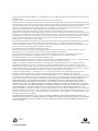
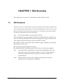
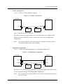
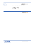
• Basic configuration
Figure 1.1 shows a connection pattern with an RCI host and RCI I/O units.
Figure 1.1 Connections to RCI I/O units
RCI host
RCI
RCI
I/O unit
RCI
I/O unit
RCI cables are connected in sequence to respective units using T-branch connectors.
RCI terminating resistors must be connected to the T-branch connectors at both ends
of a set of RCI connections.
Up to 32 RCIs including the RCI main unit can be connected.
Note that the maximum RCI cable length is 150 meters.
Use the repeater function of the external power controller to extend the cable length
used and to increase the number of connected RCI units.
Note:
1-4
The external power controller is included in the number of RCI units.
C120-E360-06EN
1.3 RCI Connection Scheme
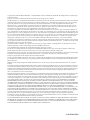
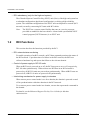
• Cluster configuration
Figure 1.2 shows a cluster connection pattern.
Figure 1.2 Cluster connections
RCI host
RCI host
RCI
RCI
RCI
I/O unit
RCI
I/O unit
Up to 32 RCI hosts can be connected.
The cluster connection requirements, such as the maximum cable length and the
number of connectable RCI I/O units, are the same as the basic configuration
requirements.
Note:
The repeater function of the external power controller cannot be used to
increase the number of RCI base cabinets.
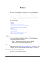
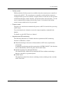
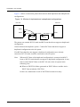
• Duplicated configuration
Figure 1.3 shows the connection pattern of a duplicated configuration.
Figure 1.3 Duplicated configuration
RCI host
RCI host
RCI#1
RCI#1
RCI#0
RCI#0
RCI#0
I/O unit
RCI#0
I/O unit
RCI hosts can be constructed in a duplicated configuration only if their XSCF units
are in a redundant configuration (duplicated configuration).
Note:
C120-E360-06EN
Do not connect an expansion XSCF unit to an RCI network connected to a
base XSCF unit.
1-5
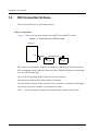
CHAPTER 1 RCI Overview
Figure 1.4 shows a connection pattern that connects both duplicated and unduplicated
configurations.
Figure 1.4 Mixture of duplicated and unduplicated configurations
RCI host
RCI host
RCI#1
RCI#0
RCI#0
RCI#0 RCI#1
I/O unit
RCI#0
I/O unit
The pattern can contain RCI I/O units and RCI hosts that do not support a duplicated
configuration.
Connect them to the duplicate system. Connect RCI hosts that do not support a
duplicated configuration to the #0 system.
If an RCI host that does not support a duplicated configuration were already
connected, RCI I/O units would be connected to the #0 system.
Note:
When an RCI host of the duplicated configuration is connected with RCI
hosts or RCI I/O units that do not support a duplicated configuration, it may
fail to control the RCI host or the RCI I/O unit on the #0 system in the
following case:
z When an XSCFU#0 failure generated an XSCF failover and the Active
XSCF Unit switched to XSCFU#1.
In this case, maintenance work of XSCFU#0 becomes necessary.
1-6
C120-E360-06EN
CHAPTER 2 Setup of the RCI for Operation
1
This chapter describes setup information for use of the RCI.
2.1
Overview of RCI Setup
The RCI can be set up as follows.
Note:
RCI setup as explained in this chapter is carried out by authorized service
personnel.
z Prepare a serially-connected PC or a PC connected to the XSCF-LAN, specify its
IP address, establish a connection to the XSCF, and use the XSCF shell.
The RCI is configured in the following types of setup:
z
z
z
z
z
RCI Setup for Initial Installation
RCI Setup for Addition of an RCI I/O Unit
RCI Setup for Addition of an RCI Base Cabinet
RCI Setup for Replacement of an RCI I/O Unit
RCI Setup for Replacement of an RCI Base Cabinet
Each setup for RCI configuration is explained in the following manner:
- Explanation 1 The explanation of each RCI setup begins with a description of the overall setup
flow.
2 Setup procedures are then explained with setting examples.
• For detailed explanations and details on options of XSCF Shell commands, see the
man pages or, Chapter 3, "Command Reference."
• This section does not explain in detail the connection between the XSCF and a PC
or terminal and methods for logging in to the XSCF. For details, see the XSCF
User’s Guide.
C120-E360-06EN
2-1
CHAPTER 2 Setup of the RCI for Operation
2.2
RCI Setup for Initial Installation
This section explains the procedure for initial RCI setup, which assumes RCI settings
have not been configured.
Note:
2.2.1
Perform this work when this system is not using any RCI I/O unit.
RCI setup flow
RCI setup for initial installation contains the following steps:
1
2
3
4
2.2.2
Confirming RCI initialization
Connecting RCI cables
Making an RCI address setting
Making an RCI construction setting
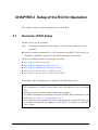
Confirming RCI initialization
Before connecting an RCI cable to an RCI host, confirm that RCI settings have been
initialized.
• To confirm RCI initialization:
1 Execute the setrci (8) command to display the RCI status.
XSCF> setrci -c stat
HOST
address 000f7fff
Inactive
The command completed successfully.
Confirm that "address" is 000f7fff (initial address value).
If RCI settings have not been initialized, perform the next step.
2 Execute the setrci (8) command to initialize RCI settings.
XSCF> setrci -c init
The command completed successfully.
2-2
C120-E360-06EN
2.2 RCI Setup for Initial Installation
2.2.3
Connecting RCI cables
Connect RCI cables.
Connect RCI units in sequence with RCI cables and their T-branch connectors.
Connect RCI terminating resistors to the T-branch connectors at both ends of a set of
RCI connections.
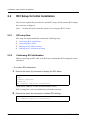
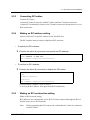
2.2.4
Making an RCI address setting
Specify "000101ff" as the RCI address for the first RCI host.
The RCI address must be unique in duplicate RCI networks.
• To specify an RCI address:
1 Execute the setrci (8) command, and specify an RCI address.
<Example> Specifying the RCI address 000101ff for the XSCF
XSCF> setrci -c set <1>
The command completed successfully.
• To confirm an RCI address:
1 Execute the setrci (8) command to display the RCI status.
XSCF> setrci -c stat
HOST
address 000101ff
Inactive
The command completed successfully.
Confirm that the "address" value is correct.
To correct the RCI address, start again from RCI initialization.
2.2.5
Making an RCI construction setting
Make an RCI network setting.
RCI addresses are automatically set for RCI I/O units connected through the RCI so
that the units can use RCI functions.
Note:
Before beginning this RCI setup work, confirm that AC cables are connected
to all RCI units.
C120-E360-06EN
2-3
CHAPTER 2 Setup of the RCI for Operation
Note:
To make an RCI construction setting for an RCI unit equipped with a main
line switch, set the main line switch to the ON position.
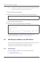
• To make an RCI construction setting:
1 Execute the setrci (8) command, and make an RCI construction setting.
XSCF> setrci -c initconfig
....................................................
The command completed successfully.
• To confirm an RCI construction setting:
1 Execute the setrci (8) command to display the RCI status.
XSCF> setrci -c stat
HOST
address 000101ff
Active
LIST
address pwr alm I/F sys-phase ctgry
000101ff OFF ACT host
The command completed successfully.
dev-cls
0001
sub-cls tm-out
0b
-
Confirm that the displayed LIST contents include the connected RCI unit.
For details on LIST contents, see Chapter 3, "Command Reference."
2.3
RCI Setup for Addition of an RCI I/O Unit
This section explains the setup procedure for adding an RCI I/O unit to this system for
which RCI setup for initial installation has already been completed.
This work can be performed while an existing domain is running.
2.3.1
RCI setup flow
RCI setup for addition of an RCI I/O unit contains the following steps:
1
2
2-4
Connecting an RCI cable
Making an RCI expansion setting
C120-E360-06EN
2.3 RCI Setup for Addition of an RCI I/O Unit
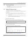
2.3.2
Connecting an RCI cable
1
2
2.3.3
Insert a T-branch connector and an RCI cable into the existing set of connections
of RCI cables.
Connect the T-branch connector to the RCI I/O unit to be added.
Making an RCI expansion setting
The added RCI I/O unit must be connected to the RCI network.
An RCI address is automatically set for the added RCI I/O unit so that the unit can use
RCI functions.
An RCI expansion setting can be made only once from an arbitrary RCI host.
Note:
Before beginning this RCI setup work, confirm that AC cables are connected
to all RCI units.
Note:
To make an RCI expansion setting for an RCI unit equipped with a main line
switch, set the main line switch to the ON position.
• To make an RCI expansion setting:
1 Execute the setrci (8) command, and make an RCI expansion setting.
XSCF> setrci -c addconfig
....................................................
The command completed successfully.
• To confirm an RCI expansion setting:
1 Execute the setrci (8) command to display the RCI status.
XSCF> setrci -c stat
HOST
address 000101ff
Active
LIST
address pwr alm I/F
sys-phase ctgry dev-cls sub-cls tm-out
000101ff OFF ACT
host 0001
0b
003001ff OFF ACT
disk 0400
04
The command completed successfully.
Confirm that the displayed LIST contents include the connected RCI I/O unit.
For details on LIST contents, see Chapter 3, "Command Reference."
C120-E360-06EN
2-5
CHAPTER 2 Setup of the RCI for Operation
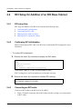
2.4
RCI Setup for Addition of an RCI Base Cabinet
2.4.1
RCI setup flow
RCI setup for addition of an RCI host contains the following steps:
1
2
3
4
2.4.2
Confirming RCI initialization
Connecting an RCI cable
Making an RCI address setting
Making an RCI expansion setting
Confirming RCI initialization
Before connecting an RCI cable to an RCI host, confirm that RCI settings have been
initialized.
• To confirm RCI initialization:
1 Execute the setrci (8) command to display the RCI status.
XSCF> setrci -c stat
HOST
address 000f7fff
Inactive
The command completed successfully.
Confirm that "address" is 000f7fff (initial address value).
If RCI settings have not been initialized, perform the next step.
2 Execute the setrci (8) command to initialize RCI settings.
XSCF> setrci -c init
The command completed successfully.
2.4.3
Connecting an RCI cable
Connect an RCI cable to the RCI host to be added.
1
2-6
Insert a T-branch connector and an RCI cable into the existing set of connections
of RCI cables.
C120-E360-06EN
2.4 RCI Setup for Addition of an RCI Base Cabinet
2
Connect the T-branch connector to the RCI host to be added.
Note:
2.4.4
Always do Confirming RCI initialization before connecting an RCI cable to
the RCI host.
Making an RCI address setting
Specify an RCI addresses in a range of 000102ff to 000120ff for the RCI host to be
added.
The RCI address must be unique in the existing RCI network.
RCI addresses must be assigned in the order of 000102ff, 000103ff, 000104ff, and so
on.
Specify the RCI address on the RCI host to be added.
• To specify an RCI address:
1 Execute the setrci (8) command, and specify an RCI address.
<Example> Specifying the RCI address 000102ff for the XSCF
XSCF> setrci -c set <2>
The command completed successfully.
Specify a decimal number for the fifth and sixth digits of the target RCI address.
A decimal number in a range of 1 to 32 can be used.
• To confirm the specified RCI address:
1 Execute the setrci (8) command to display the RCI status.
XSCF> setrci -c stat
HOST
address 000102ff
Inactive
The command completed successfully.
Confirm that the "address" value is correct.
To correct the RCI address, start again from RCI initialization.
C120-E360-06EN
2-7
CHAPTER 2 Setup of the RCI for Operation
2.4.5
Making an RCI expansion setting
The added RCI host must be connected to the RCI network.
The RCI address of the added RCI host is synchronized with those of existing RCI
hosts so that the added cabinet can use RCI functions.
Make an RCI expansion setting on the added RCI host.
Note:
Before beginning this RCI setup work, confirm that AC cables are connected
to all RCI units.
Note:
To make an RCI expansion setting for an RCI unit equipped with a main line
switch, set the main line switch to the ON position.
• To make an RCI expansion setting:
1 Execute the setrci (8) command, and make an RCI expansion setting.
XSCF> setrci -c addconfig
....................................................
The command completed successfully.
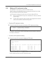
• To confirm an RCI expansion setting:
1 Execute the setrci (8) command to display the RCI status.
XSCF> setrci -c stat
HOST
address 000102ff
Active
LIST
address pwr alm I/F
sys-phase
tgry dev-cls sub-cls
000101ff OFF ACT
host 0001
0b
000102ff OFF ACT
host 0001
0b
003001ff OFF ACT
disk 0400
04
The command completed successfully.
tm-out
-
Confirm that the displayed LIST contents include the added RCI host.
For details on LIST contents, see Chapter 3, "Command Reference."
2-8
C120-E360-06EN
2.5 RCI Setup for Replacement of an RCI I/O Unit
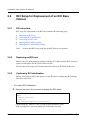
2.5
RCI Setup for Replacement of an RCI I/O Unit
2.5.1
RCI setup flow
RCI setup for replacement of an RCI I/O unit contains the following steps:
1
2
3
Confirming an RCI address
Replacing an RCI I/O Unit
Making an RCI replacement setting
Note:
2.5.2
Perform this RCI setup work for each RCI I/O unit to be replaced.
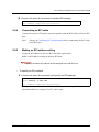
Confirming an RCI address
Confirm the RCI address or location of the RCI I/O unit to be replaced.
• To confirm an RCI address:
1 Push the service pin of the RCI I/O unit to be replaced.
2 Execute the setrci (8) command to display the address of the RCI I/O unit
whose service pin is pushed.
XSCF> setrci -c idpin
RCI:XXXX VER:XX DATE:XXXX XX/XX XX:XX;XX
The command completed successfully.
If the RCI I/O unit to be replaced has failed and cannot make a transmission, its RCI
address cannot be confirmed by the above operation. Perform the following operation
to confirm the RCI address.
C120-E360-06EN
2-9
CHAPTER 2 Setup of the RCI for Operation
3 Execute the setrci (8) command to display a list of connected RCI units.
XSCF> setrci -c stat
HOST
address 000102ff
Active
LIST
address pwr alm I/F
sys-phase
tgry dev-cls sub-cls
000101ff OFF ACT
host 0001
0b
003001ff OFF ACT
disk 0400
04
003002ff OFF INACT disk 0400
04
003003ff OFF ACT
disk 0400
04
The command completed successfully.
tm-out
-
On the list, "INACT" is displayed in the "I/F" column of the RCI I/O unit that cannot
make a transmission to the RCI.
• To confirm the location of an RCI I/O unit:
If the RCI address of the target RCI I/O unit is already known, such as because of an
error message, the location of the RCI I/O unit can be confirmed by specifying its RCI
address and triggering blinking of its LED.
1 Execute the setrci (8) command to trigger blinking of the LED of the RCI I/O
unit at the specified RCI address.
<Example> Specifying the RCI address 003002ff
XSCF> setrci -c ledon <003002ff>
.....
The command completed successfully.
2 Locate the RCI I/O unit whose LED is blinking.
3 Execute the setrci (8) command to stop the blinking LED of the RCI I/O unit.
XSCF> setrci -c ledoff
The command completed successfully.
2.5.3
Replacing an RCI I/O Unit
Remove the T-branch connector together with the RCI cables from the RCI I/O unit to
be replaced. Replace the RCI I/O unit, and connect the T-branch connector and RCI
cables to the new RCI I/O unit.
2-10
C120-E360-06EN
2.5 RCI Setup for Replacement of an RCI I/O Unit
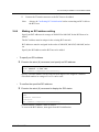
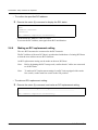
2.5.4
Making an RCI replacement setting
The added RCI I/O unit must be connected to the RCI network.
The RCI address of the added RCI I/O unit is synchronized with that of an existing
RCI host so that the unit can use RCI functions.
An RCI expansion setting can be made only once from an arbitrary RCI host.
Note:
Before beginning this RCI setup work, confirm that AC cables are connected
to all RCI units.
Note:
To make an RCI expansion setting for an RCI unit equipped with a main line
switch, set the main line switch to the ON position.
• To make an RCI replacement setting:
1 Execute the setrci (8) command, and make an RCI replacement setting.
<Example> Replacing the RCI I/O unit at the RCI address 003002ff
XSCF> setrci -c replaceconfig <003002ff>
....................................................
The command completed successfully.
In <address>, specify the RCI address (eight-digit hexadecimal number) obtained by
RCI address confirmation.
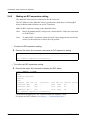
• To confirm an RCI replacement setting:
1 Execute the setrci (8) command to display the RCI status.
XSCF> setrci -c stat
HOST
address 000102ff
Active
LIST
address pwr alm I/F
sys-phase ctgry dev-cls sub-cls
000101ff OFF ACT
host 0001
0b
003001ff OFF ACT
disk 0400
04
003002ff OFF ACT
disk 0400
04
003003ff OFF ACT
disk 0400
04
The command completed successfully.
tm-out
-
On the list, confirm that "ACT" is displayed in the "I/F" column of the RCI I/O unit at
the RCI address specified for the RCI replacement setting.
C120-E360-06EN
2-11
CHAPTER 2 Setup of the RCI for Operation
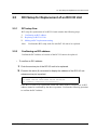
2.6
RCI Setup for Replacement of an RCI Base
Cabinet
2.6.1
RCI setup flow
RCI setup for replacement of an RCI host contains the following steps:
1
2
3
4
5
Replacing an RCI host
Confirming RCI initialization
Connecting an RCI cable
Making an RCI address setting
Making an RCI replacement setting
Note:
2.6.2
Perform this RCI setup work for each RCI host to be replaced.
Replacing an RCI host
Remove the T-branch connector together with the RCI cable from the RCI host to be
replaced, and replace the RCI host with a new one.
Do not connect the removed T-branch connector to the new RCI host at this time.
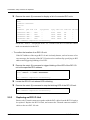
2.6.3
Confirming RCI initialization
Before connecting an RCI cable again to a new RCI host, confirm that RCI settings
have been initialized.
• To confirm RCI initialization:
1 Execute the setrci (8) command to display the RCI status.
XSCF> setrci -c stat
HOST
address 000f7fff
Inactive
The command completed successfully.
Confirm that the "address" value is 000f7fff (initial address value).
If RCI settings have not been initialized, perform the next step.
2-12
C120-E360-06EN
2.6 RCI Setup for Replacement of an RCI Base Cabinet
2 Execute the setrci (8) command to initialize RCI settings.
XSCF> setrci -c init
The command completed successfully.
2.6.4
Connecting an RCI cable
Connect the removed T-branch connector together with the RCI cable to the new RCI
host.
Note:
2.6.5
Always do Confirming RCI initialization before reconnecting the RCI cable
to the RCI host.
Making an RCI address setting
Assign an RCI address to the new RCI host after replacement.
Make an RCI address setting on the new RCI host.
Specify the same RCI address as that assigned to the old RCI host.
• To specify an RCI address:
1 Execute the setrci (8) command, and specify an RCI address.
<Example> Specifying the RCI address 000102ff for the XSCF
XSCF> setrci -c set <2>
The command completed successfully.
Specify a decimal number for the fifth and sixth digits of the target RCI address.
A decimal number in a range of 1 to 32 can be used.
C120-E360-06EN
2-13
CHAPTER 2 Setup of the RCI for Operation
• To confirm the specified RCI address:
1 Execute the setrci (8) command to display the RCI status.
XSCF> setrci -c stat
HOST
address 000102ff
Inactive
The command completed successfully.
Confirm that the "address" value is correct.
To correct the RCI address, start again from RCI initialization.
2.6.6
Making an RCI replacement setting
The new RCI host must be connected to the RCI network.
The RCI address of the new RCI host is synchronized with those of existing RCI hosts
so that the new cabinet can use RCI functions.
An RCI replacement setting can be made on the new RCI host.
Note:
Before beginning this RCI setup work, confirm that AC cables are connected
to all RCI units.
Note:
To make an RCI replacement setting for an RCI unit equipped with a main
line switch, set the main line switch to the ON position.
• To make an RCI replacement setting:
1 Execute the setrci (8) command, and make an RCI replacement setting.
XSCF> setrci -c replaceconfig
....................................................
The command completed successfully.
2-14
C120-E360-06EN
2.6 RCI Setup for Replacement of an RCI Base Cabinet
• To confirm an RCI replacement setting:
1 Execute the setrci (8) command to display the RCI status.
XSCF> setrci -c stat
HOST
address 000102ff
Active
LIST
address pwr alm I/F
sys-phase ctgry
000101ff OFF ACT
host
000102ff OFF ACT
host
003001ff OFF ACT
disk
The command completed successfully.
dev-cls
0001
0001
0400
sub-cls
0b
0b
04
tm-out
-
Confirm that the displayed LIST contents include the replacement RCI host.
For details on LIST contents, see Chapter 3, "Command Reference."
C120-E360-06EN
2-15
CHAPTER 3 Command Reference
1
3.1
setrci
• NAME
setrci - configure or display the environment of the remote cabinet interface (RCI)
• SYNOPSIS
setrci -c stat
setrci -c init [-s RCI_network]
setrci -c set host_no
setrci -c initconfig [-s RCI_network]
setrci -c addconfig [-s RCI_network]
setrci -c replaceconfig [ RCI_address]
setrci -c ledon RCI_address
setrci -c ledoff
setrci -c idpin
setrci -h
• DESCRIPTION
The setrci(8) command configures or displays information that accompanies the
initial setting and maintenance of the RCI environment.
The following can be set or displayed:
stat
init
set
initconfig
C120-E360-06EN
Displays the status of the RCI network.
Initializes the RCI setting. Initialization is only performed for the host
that executes the command. If there are other hosts connecting to the
RCI, initialization must be performed for each host.
Sets an RCI address. Use this specification when the RCI setting has been
initialized. After the setting, "-c initconfig" or "-c addconfig" must be
executed.
Makes the RCI setting on the first host. An RCI I/O unit connected via
RCI is searched for and found, and then an RCI address is assigned.
3-1
CHAPTER 3 Command Reference
addconfig
replaceconfig
ledoff
idpin
Adds an RCI I/O unit or host.
When an RCI I/O unit is added, the RCI I/O unit newly connected to RCI
is searched for and found, and then an RCI address is assigned.
When a host is added, it is also added to the RCI network. "-c set" must
be executed beforehand on the added host to set the RCI address for the
host.
Replaces an RCI I/O unit or host.
When an RCI I/O unit is replaced, the specified RCI address is assigned
to the substitute RCI I/O unit.
When a host is replaced, a substitute host is added to the RCI network
after the information of the host to be replaced is deleted from the RCI
network. "-c set" must be executed beforehand on the substitute host to
set the RCI address for the host. An RCI address cannot be specified
when replacing a host.
Stops the blinking CHECK LED of an RCI I/O unit. This specification is
used such as when the work for identifying an RCI I/O unit is completed.
Displays the RCI address of the RCI I/O unit whose ID-PIN has been
pressed. This specification is used when checking the RCI address
of an RCI I/O unit.
• PRIVILEGES
You must have platadm or fieldeng privileges to run this command.
Refer to setprivileges(8) for more information.
• OPTIONS
The following options are supported:
-c stat
-c init
-c set host_no
-c initconfig
-c addconfig
-c replaceconfig
-c ledon
-c ledoff
3-2
Displays the status of the RCI network.
Initializes the RCI setting.
Sets the address specified by host_no for the RCI address. An integer
number ranging from 0 to 32 must be specified for host_no. The
specification of one address cannot be duplicated among hosts connected
to RCI. In addition, addresses must be assigned sequentially starting from
1. "-c set" must be executed in the state where initialization has been
completed by "-c init".
Make the RCI setting at initial setting. "-c initconfig" must be executed
when the RCI setting has been initialized by "-c init" and the RCI address
has been set by "-c set".
Makes the RCI setting for when an RCI I/O unit or host is added.
Makes the RCI setting for when an RCI I/O unit or host is replaced.
Makes the CHECK LED of an RCI I/O unit blink.
Stops the blinking CHECK LED of an RCI I/O unit.
C120-E360-06EN
3.1 setrci
-c idpin
-h
-s RCI_network
Displays the RCI address of the RCI I/O unit whose ID-PIN has been
pressed.
Displays usage statement. When used with other options or operands, an
error occurs.
Specifies an RCI network. Either of the networks shown below can be
specified for RCI_network. The specification must be made together with
"-c init", "-c initconfig" and "-c addconfig".
RCI-0
Specifies the RCI network on the #0 side.
RCI-1
Specifies the RCI network on the #1 side
• OPERANDS
The following operands are supported:
RCI_address
Specifies a target RCI address. A value in any of the following ranges can
be specified for RCI_address:
003001ff-00307fff
007001ff-00707fff
002001ff-00207fff
006001ff-00607fff
• EXTENDED DESCRIPTION
z When "-c stat" is specified, the following states are displayed:
RCI-x
address
Active/Inactive
Mainte
RCI network name.
RCI address. It is displayed as an eight-digit hexadecimal number. When
the RCI address of the host has not been set, the default value (00ff7fff) is
displayed.
RCI state. Inactive means that the RCI is in the initial state, and Active
means that the RCI setting has been made.
Inactive
The RCI is in the initial state.
Active
The RCI setting has been made.
The mode switch is Service state.
z When the RCI state is Active, the following information is displayed after List:
address
pwr
alm
C120-E360-06EN
The address of the connected RCI unit.
Power state of the RCI unit.
ON
Powered on.
OFF
Powered off.
Alarm state of the RCI unit.
Normal state.
ALM
Alarm state.
WRN
Warning state.
3-3
CHAPTER 3 Command Reference
I/F
RCI unit interface status.
ACT
Valid state.
INACT
Invalid state.
sys-phase
Operating state of the host connected to RCI.
One of the following is displayed:
power-off
Powered off.
panic
In the panic state.
shdwn-start
Shutdown in progress.
shdwn-cmplt
Shutdown has completed.
dump-cmplt
Dump has completed.
booting
System being started.
running
System in operation.
Not support the status display.
ctgry
Category of the RCI unit.
One of the following is displayed:
host
Host unit.
disk
File unit.
rcic
External power control device.
linesw
Line switch.
Other
Other devices.
dev-cls
Device class of the RCI unit.
sub-cls
Subdevice class of the RCI unit.
tm-out
Idle monitoring timeout period of RCI. Since it doesn't support the status
display, "-" is always displayed.
• "-c init" needs to be executed in the system power-off status.
• "When -c initconfig", "-c addconfig", or "-c replaceconfig" is being executed, or the
setrcic(8) command is being executed, do not execute the setrci(8) command on another
host.
• When the setrci(8) command is executed, set all RCI units that are connected to RCI into
the power-on state or standby state.
• Executing the setrci(8) command on a model that does not support the RCI function
causes an error to occur.
3-4
C120-E360-06EN
3.1 setrci
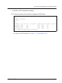
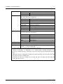
• EXAMPLES
EXAMPLE 1: Makes the first RCI setting on the first host in an M3000/M4000/
M5000 server.
C120-E360-06EN
3-5
CHAPTER 3 Command Reference
XSCF> setrci -c init
RCI-0
..........
The command completed successfully.
RCI-1
..........
The command completed successfully.
XSCF> setrci -c set 1
RCI-0
..........
The command completed successfully.
RCI-1
..........
The command completed successfully.
XSCF> setrci -c initconfig
RCI-0
..........
The command completed successfully.
RCI-1
..........
The command completed successfully.
XSCF> setrci -c stat
RCI-0
HOST
address 000101ff
Active
LIST
address pwr alm I/F sys-phase ctgry
000101ff ON ACT host
003001ff ON ACT disk
dev-cls
0001
0400
sub-cls tm-out
0b
10s
-
dev-cls
0001
sub-cls tm-out
0b
-
The command completed successfully.
RCI-1
HOST
address 004101ff
Active
LIST
address pwr alm I/F sys-phase ctgry
004101ff ON ACT host
The command completed successfully.
3-6
C120-E360-06EN
3.1 setrci
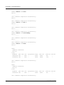
EXAMPLE 2: Makes the first RCI setting on the first host in an M8000/M9000
server.
XSCF> setrci -c init
..........
The command completed successfully.
XSCF> setrci -c set 1
..........
The command completed successfully.
XSCF> setrci -c initconfig
..........
The command completed successfully.
XSCF> setrci -c stat
RCI-0
HOST
address 000101ff
Active
LIST
address pwr alm I/F sys-phase ctgry
000101ff ON ACT host
003001ff ON ACT disk
dev-cls
0001
0400
sub-cls tm-out
0b
10s
-
The command completed successfully.
• EXIT STATUS
The following exit values are returned:
0
>0
C120-E360-06EN
Successful completion.
An error occurred.
3-7
CHAPTER 3 Command Reference
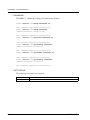
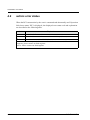
3.2
setrcic
• NAME
setrcic - make the setting of an external power control device or display its status.
• SYNOPSIS
setrcic -c exrdy RCI_address [ time]
setrcic -c opcalldisp RCI_address
setrcic -c opcallon RCI_address callNo
setrcic -c opcalloff RCI_address callNo
setrcic -h
• DESCRIPTION
The setrcic(8) command makes the setting of an external power control device or
displays its status.
The following can be set or displayed: Multiple items cannot be set at a time.
exrdy
opcalldisp
opcallon
opcalloff
Sets or displays the EXRDY monitoring timeout periods of the specified
external power control devices. If the setting is inconsistent with the
external equipment wait time, an error occurs.
Displays the status of the operator call signal of the specified external
power control devices.
Sets the operator call signals of the specified external power control
devices on.
Sets the operator call signals of the specified external power control
devices off.
• PRIVILEGES
You must have platadm or fieldeng privileges to run this command.
Refer to setprivileges(8) for more information.
3-8
C120-E360-06EN
3.2 setrcic
• OPTIONS
The following options are supported:
-c exrdy
RCI_address
[time]
-c opcalldisp
-c opcallon
RCI_address
callNo
-c opcalloff
RCI_address
callNo
-h
Sets the EXRDY monitoring timeout period of the specified external
power control devices. Set the EXRDY monitoring timeout period in
units of minutes for time. If 0 is specified, EXRDY monitoring is
disabled. If time is omitted, the EXRDY monitoring timeout period is
displayed.
Displays the status of the operator call signals of the specified external
power control devices.
Sets the operator call signals of the specified external power control
devices on. Setting is made for the devices corresponding to the bits of
callNo that contain "1".
Sets the operator call signals of the specified external power control
devices off. Setting is made for the devices corresponding to the bits of
callNo that contain "1".
Displays usage statement. When used with other options or operands, an
error occurs.
• OPERANDS
The following operands are supported:
RCI_address
time
callNo
Specifies a target RCI address. A value in any of the following ranges
can be specified for RCI_address:
003001ff-00307fff
007001ff-00707fff
Sets the EXRDY monitoring timeout period when "-c exrdy" is specified
in units of minutes. Any decimal integer number ranging from 0 to 85
can be specified.
Specifies operator call information. A two-digit hexadecimal number
can be specified.
• EXTENDED DESCRIPTION
z When the setrci(8) command or setrcic(8) command is being executed on another
host in the RCI network, do not execute the setrcic(8) command.
z When the setrcic(8) command is executed, set all RCI units that are connected to
RCI into the power-on state or standby state.
z Executing the setrcic(8) command on a model that does not support the RCI
function causes an error to occur.
C120-E360-06EN
3-9
CHAPTER 3 Command Reference
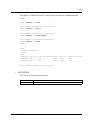
• EXAMPLES
EXAMPLE 1: Makes the setting of external power control.
XSCF> setrcic -c exrdy 003001ff 10
The command completed successfully.
XSCF> setrcic -c exrdy 003001ff
address:003001ff exrdy:10 min
The command completed successfully.
XSCF> setrcic -c opcallon 003001ff 0c
The command completed successfully.
XSCF> setrcic -c opcalldisp 003001ff
address:003001ff callNo:0c
The command completed successfully.
XSCF> setrcic -c opcalloff 003001ff 0c
The command completed successfully.
XSCF> setrcic -c opcalldisp 003001ff
address:003001ff callNo:00
The command completed successfully.
• EXIT STATUS
The following exit values are returned:
0
>0
3-10
Successful completion.
An error occurred.
C120-E360-06EN
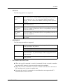
CHAPTER 4 Error Status
1
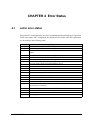
4.1
setrci error status
When the RCI construction by the setrci command ends abnormally and "Operation
failed error status: XX" is displayed, the displayed error status code and explanation
are described to the following table.
Code
00
01
02
03
04
05
06
07
08
09
0a
0b
0c
0d
0e
0f
20
30
fd
fe
ff
C120-E360-06EN
Explanation
Detected the duplicate RCI address.
RCI address of current unit is not configured or false.
Detected the duplicate RCI address of RCI host, or detected the undefined RCI
address.
RCI address of current unit is not configured.
Over maximum entry of RCI table.
Detected anomaly in RCI table receiving.
Detected anomaly in RCI table sending.
Receiving status check from undefined RCI device.
Detected the loss of RCI master.
Detected anomaly of RCI table.
Synchronous time out of RCI table.
Synchronous retry out of RCI table.
Detected anomaly of RCI table.
Failed the version check of RCI table.
Detected anomaly of RCI table.
Detected anomaly in synchronous with RCI Neuron chip.
Detected the duplicate RCI address in RCI I/O unit (Expansion file unit,
External power controller).
Detected the duplicate RCI address in RCI I/O unit (Line selector switch).
RCI construction cannot be constructed, or it was cancelled.
Other RCI unit is constructing the RCI network.
RCI setup procedure is false.
4-1
CHAPTER 4 Error Status
4.2
setrcic error status
When the RCI construction by the setrcic command ends abnormally and "Operation
failed error status: XX" is displayed, the displayed error status code and explanation
are described to the following table.
Code
-1
-2
Explanation
Detected an RCI transmission error.
Terminated the command execution due to RCI busy. (Note 1)
-3
Internal error occurred in XSCF. (Note 2)
Note 1: After a certain period of time, re-execute the setrcic command. When this case
reappears, please contact our field engineer.
Note 2: Please contact our field engineer.
4-2
C120-E360-06EN
Back Cover