1
C120-E361-04EN
SPARC® Enterprise
M4000/M5000/M8000/M9000 Server
RCI Build Procedure
ABOUT THIS PRODUCT
This product is designed and manufactured for use in standard applications such as
office work, personal device, household appliance, and general industrial
applications. This product is not intended for use in nuclear-reactor control systems,
aeronautical and space systems, air traffic control systems, mass transportation
control systems, medical devices for life support, missile launch control systems or
other specialized uses in which extremely high levels of reliability are required, the
required levels of safety cannot be guaranteed, or a failure or operational error could
be life-threatening or could cause physical injury (referred to hereafter as "high-risk"
use). You shall not use this product without securing the sufficient safety required for
high-risk use. If you wish to use this product for high-risk use, please consult with
sales representatives in charge before such use.
TRADEMARK ACKNOWLEDGEMENTS
z UNIX is a registered trademark of The Open Group in the United States and other
countries, licensed exclusively through X/Open Company Limited.
z Sun, Sun Microsystems, the Sun Logo, Solaris and all Solaris based marks and
logos are trademarks or registered trademarks of Sun Microsystems, Inc. in the
U.S. and other countries, and are used under license.
z Ethernet is a registered trademark of Xerox Corporation in the United States and in
certain other countries.
z All SPARC trademarks are registered trademarks of SPARC International, Inc.
Products bearing the SPARC trademarks are based on an architecture developed by
Sun Microsystems, Inc.
z All other product names mentioned herein are the trademarks or registered
trademarks of their respective owners.
z System and product names in this manual are not always noted with trademark or
registered trademark symbols(™), (®).
The contents of this manual may be revised without prior notice.
The contents of this manual shall not be disclosed in any way or reproduced in any
media without the express written permission of Fujitsu Limited.
All Rights Reserved, Copyright © FUJITSU LIMITED 2007
C120-E361-04EN
Preface
1
This manual explains the RCI build procedure of the SPARC Enterprise M4000/M5000/M8000/M9000 server.
This manual is intended for authorized service personnel who perform maintenance work of the server or field
engineers.
In this manual, the verification of the standalone operation of the server is assumed to have been completed. Read
this manual together with the reference manuals cited in it.
This manual explains the following:
z Structure and Contents of This Manual
z SPARC Enterprise Mx000 Servers Documentation
z Text Conventions
z Prompt Notations
z Syntax of the Command Line Interface (CLI)
Structure and Contents of This Manual
This manual is organized as described below.
Chapter 1, "RCI Build Procedure"
Explains the initial build procedure of the Remote Cabinet Interface (RCI) in the installation work.
Appendix A, "Troubleshooting."
Explains how to deal with possible problems during the RCI setup.
C120-E361-04EN
i
Preface
SPARC Enterprise Mx000 Servers Documentation
The manuals listed below are provided for reference.
Book Titles
SPARC Enterprise M4000/M5000 Servers Site Planning Guide
SPARC Enterprise M8000/M9000 Servers Site Planning Guide
SPARC Enterprise Equipment Rack Mounting Guide
SPARC Enterprise M4000/M5000 Servers Getting Started Guide
SPARC Enterprise M8000/M9000 Servers Getting Started Guide
SPARC Enterprise M4000/M5000 Servers Overview Guide
SPARC Enterprise M8000/M9000 Servers Overview Guide
Important Safety Information for Hardware Systems
SPARC Enterprise M4000/M5000 Servers Safety and Compliance Guide
SPARC Enterprise M8000/M9000 Servers Safety and Compliance Guide
External I/O Expansion Unit Safety and Compliance Guide
SPARC Enterprise M4000 Server Unpacking Guide
SPARC Enterprise M5000 Server Unpacking Guide
SPARC Enterprise M8000/M9000 Servers Unpacking Guide
SPARC Enterprise M4000/M5000 Servers Installation Guide
SPARC Enterprise M8000/M9000 Servers Installation Guide
SPARC Enterprise M4000/M5000 Servers Service Manual
SPARC Enterprise M8000/M9000 Servers Service Manual
External I/O Expansion Unit Installation and Service Manual
SPARC Enterprise M4000/M5000/M8000/M9000 Servers RCI Build Procedure
SPARC Enterprise M4000/M5000/M8000/M9000 Servers Administration Guide
SPARC Enterprise M4000/M5000/M8000/M9000 Servers XSCF User’s Guide
SPARC Enterprise M4000/M5000/M8000/M9000 Servers XSCF Reference Manual
SPARC Enterprise M4000/M5000/M8000/M9000 Servers Dynamic Reconfiguration
(DR) User’s Guide
SPARC Enterprise M4000/M5000/M8000/M9000 Servers Capacity on Demand (COD)
User’s Guide
SPARC Enterprise M4000/M5000/M8000/M9000 Servers RCI User’s Guide
SPARC Enterprise M4000/M5000 Servers Product Notes
SPARC Enterprise M8000/M9000 Servers Product Notes
External I/O Expansion Unit Product Notes
Manual Codes
C120-H015
C120-H014
C120-H016
C120-E345
C120-E323
C120-E346
C120-E324
C120-E391
C120-E348
C120-E326
C120-E457
C120-E349
C120-E350
C120-E327
C120-E351
C120-E328
C120-E352
C120-E330
C120-E329
C120-E361
C120-E331
C120-E332
C120-E333
C120-E335
C120-E336
C120-E360
Go to the Web
Go to the Web
C120-E456
(a) Manuals on the Web
The latest versions of all the SPARC Enterprise Series manuals are available at the following websites:
Global Site
http://www.fujitsu.com/sparcenterprise/manual/
Japanese Site
http://primeserver.fujitsu.com/sparcenterprise/manual/
Note:
ii
Product Notes and Release Notes are available on the website only. Please check for the recent
update on your product.
C120-E361-04EN
Preface
(b) Documentation CD
For the Documentation CD, please contact your local sales representative.
- SPARC Enterprise M4000/M5000 Servers Documentation CD (C120-E365)
- SPARC Enterprise M8000/M9000 Servers Documentation CD (C120-E364).
(c) Manual included on the Enhanced Support Facility x.x CD-ROM disk
Remote maintenance service
Book Titles
Manual Codes
Enhanced Support Facility User's Guide for REMCS
C112-B067
(d) Provided in system
Man page of the XSCF
Note:
The man page can be referenced on the XSCF Shell, and it provides the same content as the
SPARC Enterprise M4000/M5000/M8000/M9000 Servers XSCF Reference Manual.
(e) Solaris Operating System-related manuals
http://docs.sun.com
(f) Information on Using the RCI function
For information on using the RCI function, refer to the SPARC Enterprise M4000/M5000/M8000/M9000
Servers RCI Build Procedure (This manual) and SPARC Enterprise M4000/M5000/M8000/M9000 Servers
RCI User’s Guide provided on the website.
Text Conventions
This manual uses the following fonts and symbols to express specific types of information:
Typeface or symbol
AaBbCc123
AaBbCc123
Meaning
What you type, when contrasted
with on-screen computer output.
This font represents the example of
command input in the frame.
The names of commands, files, and
directories; on-screen computer
output.
This font represents the example of
command input in the frame.
Example
XSCF> adduser jsmith
XSCF> showuser -p
User Name: jsmith
Privileges: useradm
auditadm
Italic
Indicates the name of a reference manua See the XSCF User's Guide.
""
Indicates names of chapters, sections, See Chapter
items, buttons, or menus
Installation."
C120-E361-04EN
2,
"Preparation
for
iii
Preface
Prompt Notations
The notation used for prompts in this manual is shown below.Syntax of the Command Line Interface (CLI)
Shell
XSCF
C shell
C shell superuser
Bourne shell and Korn shell
Bourne shell and Korn shell super-users
OpenBoot PROM
Prompt notation
XSCF>
machine-name%
machine-name#
$
#
ok
Syntax of the Command Line Interface (CLI)
The command syntax is described below.
Command syntax
The command syntax is as follows:
z A variable that requires input of a value is enclosed in < >.
z An optional element is enclosed in [ ].
z A group of options for an optional keyword is enclosed in [ ] and delimited by |.
z A group of options for a mandatory keyword is enclosed in {} and delimited by |.
z The command syntax is shown in a frame.
Example
XSCF>
iv
showuser -a
C120-E361-04EN
Reader's Comment Form
Reader's Comment Form
C120-E361-04EN
v
Reader's Comment Form
FOLD AND TAPE
NO POSTAGE
NECESSARY
IF MAILED
IN THE
UNITED STATES
BUSINESS REPLY MAIL
FIRST-CLASS MAIL PERMIT NO 741 SUNNYVALE CA
POSTAGE WILL BE PAID BY ADDRESSEE
FUJITSU COMPUTER SYSTEMS
AT TENTION ENGINEERING OPS M/S 249
1250 EAST ARQUES AVENUE
P O BOX 3470
SUNNYVALE CA 94088-3470
FOLD AND TAPE
vi
C120-E361-04EN
Contents
Preface . . . . . . . . . . . . . . . . . . . . . . . . . . . . . . . . . . . . . . . . . . . . . . . . . . . . . . . . . . .
i
Reader's Comment Form . . . . . . . . . . . . . . . . . . . . . . . . . . . . . . . . . . . . . . . . . . .
v
CHAPTER 1RCI Build Procedure . . . . . . . . . . . . . . . . . . . . . . . . . . . . . . . .
1-1
1.1
RCI Overview . . . . . . . . . . . . . . . . . . . . . . . . . . . . . . . . . . . . . . . . . . . . . . . . . . . .
1.1.1
1.2
Overview of RCI connection . . . . . . . . . . . . . . . . . . . . . . . . . . . . . . . . . . .
1-1
RCI command . . . . . . . . . . . . . . . . . . . . . . . . . . . . . . . . . . . . . . . . . . . . . . . . . . . .
1-3
1.2.1
1.3
Command list . . . . . . . . . . . . . . . . . . . . . . . . . . . . . . . . . . . . . . . . . . . . . .
1-3
RCI Setup . . . . . . . . . . . . . . . . . . . . . . . . . . . . . . . . . . . . . . . . . . . . . . . . . . . . . . .
1-4
1.3.1
New setup for a single RCI Host and two RCI I/O units . . . . . . . . . . . . . .
1-4
1.3.2
New setup of two RCI Hosts . . . . . . . . . . . . . . . . . . . . . . . . . . . . . . . . . . .
1-6
1.3.3
When an RCI I/O unit is added later . . . . . . . . . . . . . . . . . . . . . . . . . . . . .
1-8
1.3.4
When a RCI Host is added later . . . . . . . . . . . . . . . . . . . . . . . . . . . . . . . .
1-9
1.3.5
Connection of RCI . . . . . . . . . . . . . . . . . . . . . . . . . . . . . . . . . . . . . . . . . . .
1-10
Appendix ATroubleshooting . . . . . . . . . . . . . . . . . . . . . . . . . . . . . . . . . . .
A.1
1-1
A-1
In the Case Where Setrci Command Ended Abnormally and Displayed “Operation Failed
Error Status: XX” . . . . . . . . . . . . . . . . . . . . . . . . . . . . . . . . . . . . . . . . . . . . . . . . . . A-1
A.2
In the Case Where RCI Status of RCI Host Changes From ACTIVE to INACTIVE
C120-E361-04EN
A-4
vii
Contents
viii
C120-E361-04EN
Contents
Figures
Figure 1.1 Basic configuration . . . . . . . . . . . . . . . . . . . . . . . . . . . . . . . . . . . . . . . . .
Figure 1.2 Cluster configuration . . . . . . . . . . . . . . . . . . . . . . . . . . . . . . . . . . . . . . . .
Figure 1.3 Duplicated configuration . . . . . . . . . . . . . . . . . . . . . . . . . . . . . . . . . . . . .
Figure 1.4 Mixture of duplicated and unduplicated configurations . . . . . . . . . . . . . .
Figure 1.5 New setup for a single RCI Host and two RCI I/O units . . . . . . . . . . . . .
Figure 1.6 New setup of two RCI Hosts . . . . . . . . . . . . . . . . . . . . . . . . . . . . . . . . . .
Figure 1.7 When an RCI I/O unit is added later . . . . . . . . . . . . . . . . . . . . . . . . . . . .
Figure 1.8 When a RCI Hosts is added later . . . . . . . . . . . . . . . . . . . . . . . . . . . . . .
Figure 1.9 RCI branching connector connection of a midrange server . . . . . . . . . .
Figure 1.10 RCI branching connector connection of a high-end server . . . . . . . . . .
C120-E361-04EN
1-1
1-2
1-2
1-2
1-4
1-6
1-8
1-9
1-11
1-11
ix
Contents
x
C120-E361-04EN
Contents
Tables
Table 1.1Command list . . . . . . . . . . . . . . . . . . . . . . . . . . . . . . . . . . . . . . . . . . . . . .
Table A.1The Error Status Code and Explanation . . . . . . . . . . . . . . . . . . . . . . . . . .
C120-E361-04EN
1-3
A-1
xi
CHAPTER 1 RCI Build Procedure
This chapter explains the following items regarding the initial build procedure of the
Remote Cabinet Interface (RCI) in the installation work.
- RCI Overview
- RCI command
- RCI Setup
1.1
RCI Overview
RCI is an interface to connect RCI Host (general name for main units supporting RCI
and for RCI I/O units).
In this manual, a base cabinet and an I/O unit that support the RCI are referred to as an
RCI Host and an RCI I/O unit, respectively. Furthermore, RCI Hosts and RCI I/O
units are generally referred to as RCI device.
To connect RCI I/O units or to use the RCI asynchronous monitoring functions for an
FJ cluster, a setup using the RCI setup commands is required in addition to the
connection with RCI cables.
1.1.1
Overview of RCI connection
There are two types of main unit: midrange servers equipped with one RCI and highend servers equipped with two RCIs.
I/O units include units equipped with one RCI and units equipped with two RCIs.
The following figures show different RCI connection patterns:
RCI Hosts
RCI
RCI
RCI I/O unit
RCI
RCI I/O unit
Figure 1.1 Basic configuration
C120-E361-04EN
1-1
CHAPTER 1 RCI Build Procedure
RCI Hosts
RCI Hosts
RCI
RCI
RCI
RCI I/O unit
RCI
RCI I/O unit
Figure 1.2 Cluster configuration
RCI Hosts
RCI Hosts
RCI#1
RCI#1
RCI#0
RCI#0
RCI#0
RCI#0
RCI I/O unit
RCI I/O unit
Figure 1.3 Duplicated configuration
RCI Hosts
RCI Hosts
RCI#1
RCI#0
RCI#0
RCI#0
RCI#1
RCI I/O unit
RCI#0
RCI I/O unit
Figure 1.4 Mixture of duplicated and unduplicated configurations
1-2
C120-E361-04EN
1.2 RCI command
1.2
RCI command
RCI commands are used to display RCI configuration information and set node
addresses.
To connect I/O units equipped with RCI ports, a setup using RCI commands is
required in addition to the connection with RCI cables.
Remarks: When you use the terminal function of the External power controller,
perform the setrcic command and confirm setting or connection of the
External power controller. For details of the setrcic command, see the RCI
User's Guide or man page.
1.2.1
Command list
The RCI commands are explained below.
Table 1.1 Command list
Command
setrci -c stat
Function
Displays RCI configuration information. This command
is used after the RCI setup to verify
that the settings of the host and I/O units have been made
correctly.
setrci -c init
Initializes the RCI configuration information.
If other host units are connected through the RCI, the
RCI settings must be initialized on each host unit.
You can use this command if the system is powered off.
setrci -c set [host_no] Sets up an RCI Host node.
Before this command can be executed, the RCI settings
must already have been initialized.
host_noÅF Integer numbers from 1 to 32 are assigned
in this order.
setrci -c initconfig
Assigns an RCI address to an I/O unit connected via RCI.
Before this command can be executed, the RCI Host
node settings must already have been made.
setrci -c addconfig
Makes the RCI settings for the case that a host unit or an
I/O unit is added.
C120-E361-04EN
1-3
CHAPTER 1 RCI Build Procedure
1.3
RCI Setup
This section explains the RCI setup for the following cases:
z
z
z
z
New setup for a single RCI Host and two RCI I/O units
New setup of two RCI Hosts
When an RCI I/O unit is added later
When a RCI Host is added later
Remarks: Please refer to Appendix A, "Troubleshooting." when there is a problem at
RCI setup.
1.3.1
New setup for a single RCI Host and two RCI I/O units
RCI Host
RCI I/O unit
RCI I/O unit
Figure 1.5 New setup for a single RCI Host and two RCI I/O units
1 Log in to the XSCF Shell.
2 Execute the setrci -c stat command to display the RCI status.
XSCF> setrci -c stat
HOST
address 000f7fff
Inactive
The command completed successfully
3 Verify that the RCI address is 000f7fff.
Remarks: 000f7fff is the default value of the RCI address. If the default value is not
set, execute the setrci -c init command to initialize the value.
If the system is powered off, you can use the setrci -c init command.
1-4
C120-E361-04EN
1.3 RCI Setup
XSCF> setrci -c init
The command completed successfully
4 Connect the main unit and I/O units with RCI cables (see Figure 1.5).
Connect an RCI branching connector to each of the RCI ports, and connect them with
RCI cables by using a daisy-chain connection.
Connect an RCI terminating resistor to the branching connector at either end of the
RCI connection. Refer to Section 1.3.5, "Connection of RCI."
5 Turn on the AC input to all the RCI device which are in the RCI connection.
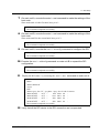
6 Execute the setrci -c set command to make the settings of the host node.
Since the main unit is the first unit, host_no is 1.
XSCF> setrci -c set 1
The command completed successfully
7 Execute the setrci -c initconfig command to configure the RCI.
XSCF> setrci -c initconfig
The command completed successfully
8 Execute the setrci -c stat command to display the RCI status.
XSCF> setrci -c stat
HOST
address 000101ff
Active
LIST
address pwr alm I/F sys-phase ctgry dev-cls sub-cls tm-out
000101ff OFF - ACT power-off host 0001 0b 003001ff OFF - ACT power-off disk 0400 04 003002ff OFF - ACT power-off disk 0400 04 The command completed successfully
9 Verify that all the RCI device in the RCI connection are incorporated.
C120-E361-04EN
1-5
CHAPTER 1 RCI Build Procedure
1.3.2
New setup of two RCI Hosts
RCI
RCI
Host A
Host B
RCI I/O unit
RCI I/O unit
Figure 1.6 New setup of two RCI Hosts
1 Log in to the XSCF Shell.
2 On main unit A, execute the setrci -c stat command to display the RCI status.
XSCF> setrci -c stat
HOST
address 000f7fff
Inactive
The command completed successfully
3 Verify that the RCI address is 000f7fff.
Remarks: 000f7fff is the default value of the RCI address. If the default value is not
set, execute the setrci -c init command to initialize the value.
If the system is powered off, you can use the setrci -c init command.
XSCF> setrci -c init
The command completed successfully
4 In a similar manner, display the RCI status of main unit B to verify that the RCI
address is 000f7fff.
5 Connect the main unit and I/O units with RCI cables (see Figure 1.6).
Connect an RCI branching connector to each of the RCI ports, and connect them with
RCI cables by using a daisy-chain connection.
Connect an RCI terminating resistor to the branching connector at either end of the
RCI connection. Refer to Section 1.3.5, "Connection of RCI."
6 Turn on the AC input to all the RCI device which are in the RCI connection.
1-6
C120-E361-04EN
1.3 RCI Setup
7 On main unit A, execute the setrci -c set command to make the settings of the
host node.
Since main unit A is the first unit, host_no is 1.
XSCF> setrci -c set 1
The command completed successfully
8 On main unit B, execute the setrci -c set command to make the settings of the
host node.
Since main unit B is the second unit, host_no is 2.
XSCF> setrci -c set 2
The command completed successfully
9 On main unit A, execute the setrci -c initconfig command to configure the RCI.
XSCF> setrci -c initconfig
The command completed successfully
10 Execute the setrci -c addconfigcommand on main unit B to expand the RCI
configuration.
XSCF> setrci -c addconfig
The command completed successfully
11 Display the RCI status by executing the setrci -c stat command on main unit A.
XSCF> setrci -c stat
HOST
address 000101ff
Active
LIST
address pwr alm I/F sys-phase ctgry dev-cls sub-cls tm-out
000101ff OFF - ACT -host 0001 0b
000102ff OFF - ACT -host 0001 0b
003001ff OFF - ACT -disk 0400 04
003002ff OFF - ACT -disk 0400 04
The command completed successfully
12 Verify that all the RCI device in the RCI connection are incorporated.
C120-E361-04EN
1-7
CHAPTER 1 RCI Build Procedure
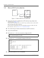
1.3.3
When an RCI I/O unit is added later
RCI Host
Addition
RCI I/O unit
RCI I/O unit
Figure 1.7 When an RCI I/O unit is added later
1 Connect the I/O unit to be added with an RCI cable by using a daisy-chain
connection (see Figure 1.7).
Connect an RCI branching connector to the RCI port, and then connect it with an RCI
cable by using a daisy-chain connection.
Connect an RCI terminating resistor to the branching connector at either end of the
RCI connection. Refer to Section 1.3.5, "Connection of RCI."
2 Turn on the AC input to all the units which are in the RCI connection.
3 Log in to the XSCF Shell.
4 Execute the setrci -c addconfig command to configure the RCI.
XSCF> setrci -c addconfig
The command completed successfully
5 Execute the setrci -c stat command to display the RCI status.
XSCF> setrci -c stat
HOST
address 000101ff
Active
LIST
address pwr alm I/F sys-phase ctgry dev-cls sub-cls tm-out
000101ff OFF - ACT -host 0001 0a
003001ff OFF - ACT -disk 0400 04
003002ff OFF - ACT -disk 0400 04
The command completed successfully
6 Verify that the added I/O unit is incorporated.
1-8
C120-E361-04EN
1.3 RCI Setup
1.3.4
When a RCI Host is added later
RCI
RCI
Host A
Host B
Addition
RCI I/O unit
RCI I/O unit
Figure 1.8 When a RCI Hosts is added later
1 Log in to the XSCF Shell.
2 On main unit B, which is to be added, execute the setrci -c stat command to
display the RCI status.
XSCF> setrci -c stat
HOST
address 000f7fff
Inactive
The command completed successfully
3 Verify that the RCI address is 000f7fff.
Remarks: 000f7fff is the default value of the RCI address. If the default value is not
set, execute the setrci -c init command to initialize the value.
If the system is powered off, you can use the setrci -c init command.
XSCF> setrci -c init
The command completed successfully
4 Connect main unit B, which is to be added, with an RCI cable (see Figure 1.8).
Connect an RCI branching connector to each of the RCI ports, and connect them with
RCI cables by using a daisy-chain connection.
Connect an RCI terminating resistor to the branching connector at either end of the
RCI connection. Refer to Section 1.3.5, "Connection of RCI."
5 Turn on the AC input to all the RCI device which are in the RCI connection.
6 On main unit B, execute the setrci -c set command to make the settings of the
host node.
Since the main unit is the second unit, host_no is 2.
C120-E361-04EN
1-9
CHAPTER 1 RCI Build Procedure
XSCF> setrci -c set 2
The command completed successfully
7 Execute the setrci -c addconfig command on main unit B to expand the RCI
configuration.
XSCF> setrci -c addconfig
The command completed successfully
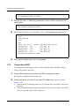
8 Display the RCI status by executing the setrci -c statcommand on main unit A.
XSCF> setrci -c stat
HOST
address 000102ff
Active
LIST
address pwr alm I/F sys-phase ctgry
000101ff OFF - ACT -host
000102ff OFF - ACT -host
003001ff OFF - ACT -disk
003002ff OFF - ACT -disk
The command completed successfully
dev-cls sub-cls tm-out
0001 0b 0001 0b 0400 04 0400 04 -
9 Verify that the added main unit is incorporated.
1.3.5
Connection of RCI
According to the following procedure, connect different units with RCI cables by
using a daisy-chain connection.
1 Prepare RCI branching connectors and RCI terminating resistors.
All of them are supplied with the main unit.
2 Connect the main unit and I/O units with RCI cables (see Figure 1.9 and
Figure 1.10.)
1 Connect the RCI branching connector (1) to the RCIport on an XSCF unit of the
main unit.
2 Connect the RCI branching connector and the RCI port of an I/O unit with an RCI
cable (2) by using a daisy-chain connection.
1-10
C120-E361-04EN
1.3 RCI Setup
Remarks: Up to 32 RCIs including the RCI main unit can be connected. Use the
repeater function of the external power controller to extend the cable length
used and to increase the number of connected RCI device. Note that the
maximum RCI cable length is 150 meters.
Remarks: The external power controller is included in the number of RCI device
(1)
(2)
Figure 1.9 RCI branching connector connection of a midrange server
(1)
(2)
Figure 1.10 RCI branching connector connection of a high-end server
3
Connect the RCI terminating resistor to the branching connector that is at the end
of the RCI connection.
C120-E361-04EN
1-11
Appendix A Troubleshooting
A
This appendix explains how to deal with possible problems during the RCI setup.
z In the Case Where Setrci Command Ended Abnormally and Displayed “Operation
Failed Error Status: XX”
z In the Case Where RCI Status of RCI Host Changes From ACTIVE to INACTIVE
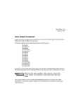
A.1
In the Case Where Setrci Command Ended
Abnormally and Displayed “Operation Failed
Error Status: XX”
When the RCI construction by the setrci command ended abnormally and "Operation
failed error status: XX" is displayed, the displayed error status code, explanation, and
remedy pattern are described to the following table.
Table A.1 The Error Status Code and Explanation
Code
00
01
02
03
04
05
06
07
08
09
0a
0b
0c
0d
0e
0f
Explanation
Detected the duplicate RCI address.
RCI address of current unit is not configured or false.
Detected the duplicate RCI address of RCI host, or detected the
undefined RCI address.
RCI address of current unit is not configured.
Over maximum entry of RCI table.
Detected anomaly in RCI table receiving.
Detected anomaly in RCI table sending.
Receiving status check from undefined RCI device.
Detected the loss of RCI master.
Detected anomaly of RCI table.
Synchronous time out of RCI table.
Synchronous retry out of RCI table.
Detected anomaly of RCI table.
Failed the version check of RCI table.
Detected anomaly of RCI table.
Detected anomaly in synchronous with RCI Neuron chip.
C120-E361-04EN
Remedy
pattarn
Pattern A
Pattern B
Pattern C
Pattern B
Pattern D
Pattern C
Pattern C
Pattern C
Pattern C
Pattern C
Pattern C
Pattern C
Pattern C
Pattern C
Pattern C
Pattern E
A-1
Appendix A Troubleshooting
Table A.1 The Error Status Code and Explanation
Code
20
30
fd
fe
ff
A-2
Explanation
Detected the duplicate RCI address in RCI I/O unit (Expansion file
unit, External power controller).
Detected the duplicate RCI address in RCI I/O unit (Line selector
switch).
RCI construction cannot be constructed, or it was cancelled.
Other RCI unit is constructing the RCI network.
RCI setup procedure is false.
Remedy
pattarn
Pattern C
Pattern F
Pattern G
Pattern A
Pattern A
C120-E361-04EN
A.1 In the Case Where Setrci Command Ended Abnormally and Displayed “Operation Failed Error Status: XX”
Remedy pattarn
z Pattern A
1
2
Check the RCI setup procedure, the RCI address value and the connection.
1
Check the setting of the RCI address and the duplicate of the RCI address by setrci -c stat command.
2
Check whether the othr RCI host that doesn't execute the RCI initialization is connected.
In the case of anomaly, retry RCI setup in correct procedure.
z Pattern B
1
Check the RCI address value of current unit by setrci -c stat command.
2
In the case of anomaly, retry RCI setup in correct procedure.
z Pattern C
1
Check the RCI address value of current unit and other unit by setrci -c stat command.
2
In the case of anomaly, retry RCI setup in correct procedure.
z Pattern D
1
Check whether 95 and more units of RCI I/O unit (include the External power controller) are not connected.
2
When 95 and more units are connected, change the connection configuration to 94 and less units (include the
External power controller), and retry RCI setup.
z Pattern E
1
Replace the XSCF board.
2
After the replacement of the XSCF unit, retry RCI setup.
z Pattern F
1
Check whether RCI address value of the Line selector switch is not duplicated.
2
If the duplicate, change the RCI address of the Line selector switch, and retry RCI setup. To change the RCI
address of the Line selector switch, refer to its manuals.
z Pattern G
Check the state of XSCF, and execute either of the following operations.
When XSCF reboot or redundancy are working, execute the setrci command after these are completed.
If the above-mentioned doesn't correspond, retry the setrci command.
C120-E361-04EN
A-3
Appendix A Troubleshooting
A.2
In the Case Where RCI Status of RCI Host
Changes From ACTIVE to INACTIVE
Remarks: When this problem has occurred, do not replace the XSCF unit because it
is not a failure of the XSCF unit.
This problem is occurred by the mistake of the RCI construction procedure and the
RCI connection.
t occurrs when the same RCI address is set and constructed, or, when connecting with
the RCI network of the construction of the RCI host that has not been initialized.
Confirm whether to correspond to this problem. The procedure is the following:
1 Excute showlogs command, and check whether RCI configuration conflict is
generated in error log.
2 When that message was generated, check the RCI establishment procedure,
the RCI address value and the connection.
3 In the case of anomaly, correct the RCI address or the connection of relevant
device according to the change procedure of each device.
4 Refer to Chapter 1.3.4, "When a RCI Host is added later" and retry RCI
establishment.
A-4
C120-E361-04EN
Back Cover