1
FUJITSU Server
PRIMEQUEST 2000 Series
Administration Manual
C122-E175-01EN
Preface
Preface
This manual describes the functions and features of the PRIMEQUEST 2000 series. The manual is intended for system
administrators.
For details on the regulatory compliance statements and safety precautions, see the PRIMEQUEST 2000 Series Safety
and Regulatory Information (C122-E171XA).
Errata and addenda for the manual
The PRIMEQUEST 2000 Series Errata and Addenda (C122-E182EN) provides errata and addenda for the manual.
Read the PRIMEQUEST 2000 Series Errata and Addenda (C122-E182EN) thoroughly in reference to the manual.
Organization of this manual
This manual is organized as follows.
CHAPTER 1 Network Environment Setup and Tool Installation
CHAPTER 2 Operating System Installation (Link)
CHAPTER 3 Component Configuration and Replacement (Add, Remove)
CHAPTER 4 PCI Card Hot Maintenance in Red Hat Enterprise Linux 6
CHAPTER 5 Replacement of HDD/SSD
CHAPTER 6 PCI Express card Hot Maintenance in Windows
CHAPTER 7 Backup and Restore
CHAPTER 8 Chapter System Startup/Shutdown and Power Control
CHAPTER 9 Configuration and Status Checking (Contents, Methods, and Procedures)
CHAPTER 10 Error Notification and Maintenance (Contents, Methods, and Procedures)
Appendix A Functions Provided by the PRIMEQUEST 2000 Series
Appendix B Physical Mounting Locations and Port Numbers
Appendix C Lists of External Interfaces Physical
Appendix D Physical Locations and BUS Numbers of Built-in I/O, and PCI Slot Mounting Locations and Slot Numbers
Appendix E PRIMEQUEST 2000 Series Cabinets (Link)
Appendix F Status Checks with LEDs
Appendix G Component Mounting Conditions
Appendix H Tree Structure of the MIB Provided with the PRIMEQUEST 2000 Series
Appendix I Windows Shutdown Settings
Appendix J How to Confirm Firmware of SAS RAID Controller Card
Appendix K Software (Link)
Appendix L Failure Report Sheet
Appendix M Information of PCI Express card
i
C122-E175-01EN
Preface
Revision History
Edition
01
Date
2014-02-18
Revised location (type) (*1)
’-’
Description
‘-’
*1: Chapter, section, and item numbers in the "Revised location" column refer to those in the latest edition of the
document. However, a number marked with an asterisk (*) denotes a chapter, section, or item in a previous
edition of the document.
ii
C122-E175-01EN
Preface
Product operating environment
This product is a computer intended for use in a computer room environment. For details on the product operating
environment, see the following manual:
PRIMEQUEST 2000 Series Hardware Installation Manual (C122-H007EN)
Safety Precautions
Alert messages
This manual uses the following alert messages to prevent users and bystanders from being injured and to prevent
property damage.
This indicates a hazardous (potentially dangerous) situation that is likely to result in death or serious
personal injury if the user does not perform the procedure correctly.
This indicates a hazardous situation that could result in minor or moderate personal injury if the user
does not perform the procedure correctly. This also indicates that damage to the product or other
property may occur if the user does not perform the procedure correctly.
This indicates information that could help the user use the product more efficiently.
Alert messages in the text
An alert statement follows an alert symbol. An alert statement is indented on both ends to distinguish it from regular text.
Similarly, one space line is inserted before and after the alert statement.
Only Fujitsu certified service engineers should perform the following tasks on this product and the
options provided by Fujitsu. Customers must not perform these tasks under any circumstances.
Otherwise, electric shock, injury, or fire may result.
- Newly installing or moving equipment
- Removing the front, rear, and side covers
- Installing and removing built-in options
- Connecting and disconnecting external interface cables
- Maintenance (repair and periodic diagnosis and maintenance)
The List of important alert items table lists important alert items.
List of important alert items
This manual does not contain important alert items.
Warning labels
Never remove the warning labels.
Warning label location (the main cabinet top)
iii
C122-E175-01EN
Preface
iv
C122-E175-01EN
Preface
Warning label location (the main cabinet left)
Warning label location (PCI_Box)
v
C122-E175-01EN
Preface
Notes on Handling the Product
About this product
This product is designed and manufactured for standard applications. Such applications include, but are not limited to,
general office work, personal and home use, and general industrial use. The product is not intended for applications that
require extremely high levels of safety to be guaranteed (referred to below as "safety-critical" applications). Use of the
product for a safety-critical application may present a significant risk of personal injury and/or death. Such applications
include, but are not limited to, nuclear reactor control, aircraft flight control, air traffic control, mass transit control, medical
life support, and missile launch control. Customers shall not use the product for a safety-critical application without
guaranteeing the required level of safety. Customers who plan to use the product in a safety-critical system are requested
to consult the Fujitsu sales representatives in charge.
Storage of accessories
Keep the accessories in a safe place because they are required for server operation.
Adding optional products
For stable operation of the PRIMEQUEST 2000 series server, use only a Fujitsu-certified optional product as an added
option.
Note that the PRIMEQUEST 2000 series server is not guaranteed to operate with any optional product not certified by
Fujitsu.
Maintenance
Only Fujitsu certified service engineers should perform the following tasks on this product and the
options provided by Fujitsu. Customers must not perform these tasks under any circumstances.
Otherwise, electric shock, injury, or fire may result.
- Newly installing or moving equipment
- Removing the front, rear, and side covers
- Installing and removing built-in options
- Connecting and disconnecting external interface cables
- Maintenance (repair and periodic diagnosis and maintenance)
Only Fujitsu certified service engineers should perform the following tasks on this product and the
options provided by Fujitsu. Customers must not perform these tasks under any circumstances.
Otherwise, product failure may result. PRIMEQUEST 2000 Series General Description
- Unpacking an optional Fujitsu product, such as an optional adapter, delivered to the customer
Modifying or recycling the product
Modifying this product or recycling a secondhand product by overhauling it without prior approval
may result in personal injury to users and/or bystanders or damage to the product and/or other
property.
Note on erasing data from hard disks when disposing of the product or transferring it
Disposing of this product or transferring it as is may enable third parties to access the data on the hard disk and use it for
unforeseen purposes. To prevent the leakage of confidential information and important data, all of the data on the hard
disk must be erased before disposal or transfer of the product.
However, it can be difficult to completely erase all of the data from the hard disk. Simply initializing (reformatting) the hard
disk or deleting files on the operating system is insufficient to erase the data, even though the data appears at a glance to
have been erased. This type of operation only makes it impossible to access the data from the operating system.
Malicious third parties can restore this data.
If you save your confidential information or other important data on the hard disk, you should completely erase the data,
instead of simply carrying out the aforementioned operation, to prevent the data from being restored. To prevent important
data on the hard disk from being leaked when the product is disposed of or transferred, you will need to take care to erase
all the data recorded on the hard disk on your own responsibility.
vi
C122-E175-01EN
Preface
Furthermore, if a software license agreement restricts the transfer of the software (operating system and application
software) on the hard disk in the server or other product to a third party, transferring the product without deleting the
software from the hard disk may violate the agreement. Adequate verification from this point of view is also necessary.
Support and service
Product and service inquiries
For all product use and technical inquiries, contact the distributor where you purchased your product, or a Fujitsu sales
representative or systems engineer (SE). If you do not know the appropriate contact address for inquiries about the
PRIMEQUEST 2000 series, use the Fujitsu contact line.
Fujitsu contact line
We accept Web inquiries. For details, visit our website:
https://www-s.fujitsu.com/global/contact/computing/PRMQST_feedback.html
Warranty
If a component failure occurs during the warranty period, we will repair it free of charge in accordance with the terms of the
warranty agreement. For details, see the warranty.
Before requesting a repair
If a problem occurs with the product, confirm the problem by referring to 11.2 Troubleshooting in the PRIMEQUEST 2000
Series Administration Manual (C122-E175ENEN). If the error recurs, contact your sales representative or a field engineer.
Confirm the model name and serial number shown on the label affixed to the right front of the device and report it. Also
check any other required items beforehand according to 11.2 Troubleshooting in the PRIMEQUEST 2000 Series
Administration Manual (C122-E175ENEN).
The system settings saved by the customer will be used during maintenance.
Manual
How to use this manual
This manual contains important information about the safe use of this product. Read the manual thoroughly to understand
the information in it before using this product. Be sure to keep this manual in a safe and convenient location for quick
reference.
Fujitsu makes every effort to prevent users and bystanders from being injured and to prevent property damage. Be sure to
use the product according to the instructions in this manual.
Manuals for the PRIMEQUEST 2000 series
The following manuals have been prepared to provide you with the information necessary to use the PRIMEQUEST 2000
series.
You can access HTML versions of these manuals at the following sites:
Japanese-language site: http://jp.fujitsu.com/platform/server/primequest/manual/2000/
Global site:
http://www.fujitsu.com/global/services/computing/server/primequest/
http://manuals.ts.fujitsu.com/
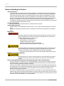
Title
PRIMEQUEST 2000 Series
Getting Started Guide
PRIMEQUEST 2000 Series
Safety and Regulatory
Information
Description
Describes what manuals you should read and how to
access important information after unpacking the
PRIMEQUEST 2000 series server. (This manual comes
with the product.)
Contains important information required for using the
PRIMEQUEST 2000 series safely.
vii
Manual code
C122-E170XA
C122-E171XA
C122-E175-01EN
Preface
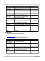
Title
PRIMEQUEST 2000 Series
Errata and Addenda
PRIMEQUEST 2000 Series
General Description
SPARC Enterprise/
PRIMEQUEST Common
Installation Planning Manual
PRIMEQUEST 2000 Series
Hardware Installation Manual
PRIMEQUEST 2000 Series
Installation Manual
PRIMEQUEST 2000 Series
User Interface Operating
Instructions
PRIMEQUEST 2000 Series
Administration Manual
PRIMEQUEST 2000 Series
Tool Reference
PRIMEQUEST 2000 Series
Message Reference
PRIMEQUEST 2000 Series
REMCS Installation Manual
PRIMEQUEST 2000 Series
Glossary
Description
Provides errata and addenda for the PRIMEQUEST 2000
series manuals. This manual will be updated as needed.
Describes the functions and features of the
PRIMEQUEST 2000 series.
Provides the necessary information and concepts you
should understand for installation and facility planning for
SPARC Enterprise and PRIMEQUEST installations.
Includes the specifications of and the installation location
requirements for the PRIMEQUEST 2000 series.
Describes how to set up the PRIMEQUEST 2000 series
server, including the steps for installation preparation,
initialization, and software installation.
Describes how to use the Web-UI and UEFI to assure
proper operation of the PRIMEQUEST 2000 series
server.
Describes how to use tools and software for system
administration and how to maintain the system
(component replacement and error notification).
Provides information on operation methods and settings,
including details on the MMB, SVAS, and UEFI functions.
Lists the messages that may be displayed when a
problem occurs during operation and describes how to
respond to them.
Describes REMCS service installation and operation
Manual code
C122-E182EN
C122-B025EN
C120-H007EN
C122-H007EN
C122-E174EN
C122-E176EN
C122-E175ENEN
C122-E177ENEN
C122-E178EN
C122-E180EN
Defines the PRIMEQUEST 2000 series related terms and C122-E179EN
abbreviations.
Related manuals
The following manuals relate to the PRIMEQUEST 2000 series.
You can access these manuals at the following site:
http://www.fujitsu.com/global/services/computing/server/primequest/
http://manuals.ts.fujitsu.com/
Contact your sales representative for inquiries about the ServerView manuals.
Title
ServerView Suite ServerView
Operations Manager Quick
Installation (Windows)
ServerView Suite ServerView
Operations Manager Quick
Installation (Linux)
ServerView Suite ServerView
Installation Manager
ServerView Suite ServerView
Operations Manager Server
Management
ServerView Suite ServerView
RAID Management User
Manual
Description
Manual code
Describes how to install and start ServerView Operations None
Manager in a Windows environment.
Describes how to install and start ServerView Operations None
Manager in a Linux environment.
Describes the installation procedure using ServerView
None
Installation Manager.
Provides an overview of server monitoring using
None
ServerView Operations Manager, and describes the user
interface of ServerView Operations Manager.
Describes RAID management using ServerView RAID
None
Manager.
viii
C122-E175-01EN
Preface
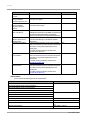
Title
ServerView Suite Basic
Concepts
ServerView Operations
Manager Installation
ServerView Agents for Linux
ServerView Operations
Manager Installation
ServerView Agents for
Windows
ServerView Mission Critical
Option User Manual
ServerView RAID Manager
VMware vSphere ESXi 5
Installation Guide
MegaRAID SAS Software
MegaRAID SAS Device
Driver Installation
Modular RAID Controller
Installation Guide
Description
Manual code
Describes basic concepts about ServerView Suite.
None
Describes installation and update installation of
ServerView Linux Agent.
None
Describes installation and update installation of
ServerView Windows Agent.
None
Describes the necessary functions unique to
PRIMEQUEST (notification via the MMB, hot replacement
command) and ServerView Mission Critical Option
(SVmco), which is required for supporting these functions.
Describes the installation and settings required to use
ServerView RAID Manager on the VMware vSphere
ESXi 5 server.
Provides technical information on using array controllers.
Refer to the manual from the second DVD for ServerView
Suite which you can purchase optionally or from the
following URL:
The Fujitsu Technology Solutions manuals server
http://manuals.ts.fujitsu.com/
Provides technical information on using array controllers.
Refer to the manual from the second DVD for ServerView
Suite which you can purchase optionally or from the
following URL:
The Fujitsu Technology Solutions manuals server
http://manuals.ts.fujitsu.com/
Provides technical information on using array controllers.
Refer to the manual from the second DVD for ServerView
Suite which you can purchase optionally or from the
following URL:
The Fujitsu Technology Solutions manuals server
http://manuals.ts.fujitsu.com/
None
None
None
None
None
Abbreviations
This manual uses the following product name abbreviations.
Formal product name
Abbreviation
Microsoft ® Windows Server ® 2012 R2 Datacenter
Windows, Windows Server 2012
Microsoft ® Windows Server ® 2012 R2 Standard
Microsoft ® Windows Server ® 2012 Datacenter
Microsoft ® Windows Server ® 2012 Standard
Microsoft ® Windows Server ® 2008 R2 Standard
Windows, Windows Server 2008
Microsoft ® Windows Server ® 2008 R2 Enterprise
Microsoft ® Windows Server ® 2008 R2 Datacenter
Red Hat ® Enterprise Linux ® 6 (for Intel64)
Linux, RHEL6, RHEL
Oracle Linux 6 (x86_64)
Oracle Linux, Oracle Linux 6
VMware vSphere (R) 5
VMware, vSphere 5.x, VMware 5, VMware
5.x
ESXi, ESXi 5, ESXi 5.x
VMware (R) ESXi (TM) 5
ix
C122-E175-01EN
Preface
Formal product name
Abbreviation
Novell (R) SUSE(R) LINUX Enterprise Server 11 Service Pack 3
SLES11 SP3
Trademarks
-
Microsoft, Windows, and Windows Server are trademarks or registered trademarks of Microsoft Corporation in the
United States and/or other countries.
-
Linux is a registered trademark of Linus Torvalds.
-
Red Hat, the Shadowman logo and JBoss are registered trademarks of Red Hat, Inc. in the U.S. and other countries.
-
Intel, Intel logo, Intel Inside, Intel Inside logo, Intel Atom, Intel Atom Inside, Intel Core, Core Inside, Intel vPro, vPro
Inside, Celeron, Celeron Inside, Itanium, Itanium Inside, Pentium, Pentium Inside, Xeon, Xeon Phi, Xeon Inside and
Ultrabook are trademarks or registered trademarks of Intel Corporation in the U.S. and other countries.
-
Ethernet is a registered trademark of Fuji Xerox Co., Ltd. in Japan and is a registered trademark of Xerox Corp. in the
United States and other countries.
-
VMware is a trademark or registered trademark of VMware, Inc. in the United States and other countries.
-
Novell and SUSE Linux Enterprise Server are trademarks of Novell, Inc.
-
Xen is a trademark or registered trademark of Citrix Systems, Inc. or its subsidiaries in the United States and other
countries.
-
Other company names and product names are the trademarks or registered trademarks of their respective owners.
-
Trademark indications are omitted for some system and product names in this manual.
Notation
This manual uses the following fonts and symbols to express specific types of information.
Font or symbols
Example
Meaning
italics
Title of a manual that you should refer to
[]
Window names as well as the names of
buttons, tabs, and drop-down menus in
windows are enclosed in brackets.
See the PRIMEQUEST 2000 Series
Installation Manual (C122-E174EN).
Click the [OK] button.
Notation for the CLI (command line interface)
The following notation is used for commands.
Command syntax
Command syntax is represented as follows.
-
Variables requiring the entry of a value are enclosed in angle brackets < >.
-
Optional elements are enclosed in brackets [ ].
-
Options for optional keywords are grouped in | (stroke) separated lists enclosed in brackets [ ].
-
Options for required keywords are grouped in | (stroke) separated lists enclosed in braces { }.
Command syntax is written in a box.
Remarks
The command output shown in the PDF manuals may include line feeds at places where there is no line feed symbol
(¥ at the end of the line).
Notes on notations
-
If you have a comment or request regarding this manual, or if you find any part of this manual unclear, please take a
moment to share it with us by filling in the form at the following webpage, stating your points specifically, and sending
x
C122-E175-01EN
Preface
the form to us:
https://www-s.fujitsu.com/global/contact/computing/PRMQST_feedback.html
-
The contents of this manual may be revised without prior notice.
-
In this manual, the Management Board and MMB firmware are abbreviated as "MMB."
-
In this manual, IOU_10GbE and IOU_1GbE are collectively referred to as IO Units.
-
Screenshots contained in this manual may differ from the actual product screen displays.
-
The IP addresses, configuration information, and other such information contained in this manual are display
examples and differ from that for actual operation.
-
The PDF file of this manual is intended for display using Adobe® Reader® in single page viewing mode at 100%
zoom.
This manual shall not be reproduced or copied without the permission of Fujitsu Limited.
Copyright 2014 FUJITSU LIMITED
xi
C122-E175-01EN
Preface
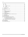
Contents
Preface................................................................................................................................................................................................................ i
CHAPTER 1
Network Environment Setup and Tool Installation .............................................................................................................1
1.1
External Network Configuration ....................................................................................................................................................1
1.2
How to Configure the External Networks (Management LAN/ Maintenance LAN/Production LAN)........................................3
1.2.1
IP addresses used in the PRIMEQUEST 2000 series server................................................................................................3
1.3
Management LAN .........................................................................................................................................................................5
1.3.1
Overview of the management LAN .........................................................................................................................................5
1.3.2
How to configure the management LAN .................................................................................................................................7
1.3.3
Redundant configuration of the management LAN ................................................................................................................9
1.4
Maintenance LAN/REMCS LAN ............................................................................................................................................... 11
1.5
Production LAN........................................................................................................................................................................... 11
1.5.1
Overview of the production LAN ........................................................................................................................................... 11
1.5.2
Redundancy of the production LAN...................................................................................................................................... 12
1.6
Management Tool Operating Conditions and Use ................................................................................................................... 12
1.6.1
MMB ....................................................................................................................................................................................... 12
1.6.2
Remote operation (BMC) ...................................................................................................................................................... 12
1.6.3
ServerView Suite ................................................................................................................................................................... 26
CHAPTER 2
Operating System Installation (Link) ................................................................................................................................ 27
CHAPTER 3
Component Configuration and Replacement (Add, Remove) ....................................................................................... 28
3.1
Partition Configuration ................................................................................................................................................................ 28
3.1.1
Partition Configuration (PPAR).............................................................................................................................................. 28
3.1.2
Setting procedure of partition in MMB Web-UI..................................................................................................................... 31
3.2
High availability configuration ..................................................................................................................................................... 31
3.2.1
Dynamic Reconfiguration (DR) ............................................................................................................................................. 31
3.2.2
Reserved SB.......................................................................................................................................................................... 36
3.2.3
Memory Operation Mode ...................................................................................................................................................... 43
3.2.4
Memory Mirror........................................................................................................................................................................ 44
3.2.5
Hardware RAID...................................................................................................................................................................... 47
3.2.6
Server View RAID.................................................................................................................................................................. 47
3.2.7
Cluster configuration .............................................................................................................................................................. 47
3.3
Replacing components............................................................................................................................................................... 47
3.3.1
Replaceable components ..................................................................................................................................................... 48
3.3.2
Component replacement conditions ..................................................................................................................................... 48
3.3.3
Replacement procedures in hot maintenance ..................................................................................................................... 49
3.3.4
Replacement procedures in cold maintenance.................................................................................................................... 49
3.3.5
Replacing the battery backup unit of the uninterrupted power supply unit (UPS) .............................................................. 49
3.3.6
Replacing the PCI SSD card................................................................................................................................................. 49
3.4
Expansion of components.......................................................................................................................................................... 51
3.4.1
Procedure of expansion in hot maintenance........................................................................................................................ 52
3.4.2
Procedure of expansion in cold maintenance ...................................................................................................................... 52
3.4.3
Expansion of PCI SSD card .................................................................................................................................................. 53
3.5
Process after switching to the Reserved SB and Automatic Partition Reboot ........................................................................ 53
3.5.1
Checking the status after switching to a Reserved SB and automatic rebooting ............................................................... 54
3.5.2
Processing after replacement of a faulty SB ........................................................................................................................ 54
3.5.3
Checking the source partition configuration information when switching to a Reserved SB ............................................. 55
3.6
Replacing the Home SB No....................................................................................................................................................... 56
CHAPTER 4
PCI Card Hot Maintenance in Red Hat Enterprise Linux 6............................................................................................. 58
4.1
Dynamic Reconfiguration (DR) .................................................................................................................................................. 58
4.1.1
DR function configuration setting .......................................................................................................................................... 58
4.1.2
dp Command Package Install/ Uninstall............................................................................................................................... 59
4.2
Hot add of SB.............................................................................................................................................................................. 59
xii
C122-E175-01EN
Preface
4.2.1
Preparing for SB hot add ....................................................................................................................................................... 59
4.2.2
Confirming the status of SB before SB hot add.................................................................................................................... 60
4.2.3
DR operation in SB hot add................................................................................................................................................... 61
4.2.4
How to deal with when timeout occurs while OS is processing SB hot add....................................................................... 62
4.2.5
Operation after SB hot add.................................................................................................................................................... 63
4.3
Hot replacement of IOU.............................................................................................................................................................. 64
4.3.1
Preparation for IOU hot replacement.................................................................................................................................... 64
4.3.2
DR operation of IOU hot replacement .................................................................................................................................. 69
4.3.3
Operation after IOU hot replacement.................................................................................................................................... 70
4.4
Hot add of IOU ............................................................................................................................................................................ 73
4.4.1
Preparation for IOU hot add .................................................................................................................................................. 73
4.4.2
DR operation of IOU hot add................................................................................................................................................. 73
4.4.3
Operation after IOU hot add .................................................................................................................................................. 74
4.5
IOU hot remove .......................................................................................................................................................................... 75
4.5.1
Preparation for IOU hot remove ............................................................................................................................................ 75
4.5.2
DR operation of IOU hot remove .......................................................................................................................................... 80
4.5.3
Operation after IOU hot remove............................................................................................................................................ 80
4.6
Hot Replacement of PCI Express Cards................................................................................................................................... 80
4.6.1
Overview of common replacement procedures for PCI Express cards.............................................................................. 81
4.6.2
PCI Express card replacement procedure in detail.............................................................................................................. 81
4.6.3
FC card (Fibre Channel card) replacement procedure........................................................................................................ 87
4.6.4
Network card replacement procedure .................................................................................................................................. 90
4.6.5
Hot replacement procedure for iSCSI (NIC)......................................................................................................................... 97
4.7
Hot Addition of PCI Express cards............................................................................................................................................. 99
4.7.1
Common addition procedures for all PCI Express cards..................................................................................................... 99
4.7.2
PCI Express card addition procedure in detail ................................................................................................................... 100
4.7.3
FC card (Fibre Channel card) addition procedure ............................................................................................................. 105
4.7.4
Network card addition procedure ........................................................................................................................................ 106
4.8
Removing PCI Express cards.................................................................................................................................................. 109
4.8.1
Common removal procedures for all PCI Express cards .................................................................................................. 109
4.8.2
PCI Express card removal procedure in detail ................................................................................................................... 109
4.8.3
FC card (Fibre Channel card) removal procedure ............................................................................................................. 110
4.8.4
Network card removal procedure........................................................................................................................................ 110
4.8.5
Hot removal procedure for iSCSI (NIC) .............................................................................................................................. 113
CHAPTER 5
Replacement of HDD/SSD............................................................................................................................................. 116
Hot replacement of HDD/SSD with Hardware RAID configuration........................................................................................ 116
5.1
5.1.1
Hot replacement of failed HDD/SSD with RAID0 configuration ........................................................................................ 116
5.1.2
Hot replacement of failed HDD/SSD with RAID 1, RAID 1E, RAID 5, RAID 6, or RAID 10 configuration...................... 116
5.2
Preventive replacement of HDD/SSD with Hardware RAID configuration............................................................................ 117
5.2.1
Preventive replacement of failed HDD/SSD with RAID0 configuration ............................................................................ 117
5.2.2
Preventive replacement of failed HDD/SSD with RAID 1, RAID 1E, RAID 5, RAID 6, or RAID 10 configuration.......... 118
5.3
Replacement of HDD/SSD in case hot replacement cannot be performed.......................................................................... 119
CHAPTER 6
PCI Express card Hot Maintenance in Windows .......................................................................................................... 120
6.1
Overview of Hot Maintenance.................................................................................................................................................. 120
6.1.1
Overall flow........................................................................................................................................................................... 120
6.2
Common Hot Plugging Procedure for PCI Express cards ..................................................................................................... 121
6.2.1
Replacement procedure...................................................................................................................................................... 121
6.2.2
Addition procedure............................................................................................................................................................... 129
6.2.3
About removal ...................................................................................................................................................................... 134
6.3
NIC Hot Plugging ...................................................................................................................................................................... 134
6.3.1
Hot plugging a NIC incorporated into teaming ................................................................................................................... 134
6.3.2
Hot plugging a non-redundant NIC ..................................................................................................................................... 138
6.3.3
NIC addition procedure........................................................................................................................................................ 138
6.4
FC Card Hot Plugging .............................................................................................................................................................. 138
6.4.1
Hot plugging an FC card incorporated with the ETERNUS multipath driver .................................................................... 139
xiii
C122-E175-01EN
Preface
6.4.2
FC card addition procedure................................................................................................................................................. 145
6.5
Hot Replacement Procedure for iSCSI.................................................................................................................................... 145
6.5.1
Confirming the incorporation of a card with MPD............................................................................................................... 146
6.5.2
Disconnecting MPD ............................................................................................................................................................. 150
CHAPTER 7
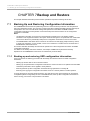
Backup and Restore ....................................................................................................................................................... 153
7.1
Backing Up and Restoring Configuration Information ............................................................................................................ 153
7.1.1
Backing up and restoring UEFI configuration information ................................................................................................. 153
7.1.2
Backing up and restoring MMB configuration information ................................................................................................. 155
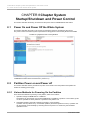
CHAPTER 8
Chapter System Startup/Shutdown and Power Control ............................................................................................... 157
8.1
Power On and Power Off the Whole System ......................................................................................................................... 157
8.2
Partition Power on and Power off ............................................................................................................................................ 157
8.2.1
Various Methods for Powering On the Partition ................................................................................................................. 157
8.2.2
Partition Power on unit......................................................................................................................................................... 158
8.2.3
Types of Power off Method of Partition............................................................................................................................... 158
8.2.4
Powering Off Partition Units................................................................................................................................................. 158
8.2.5
Procedure for Partition Power On and Power Off .............................................................................................................. 159
8.2.6
Partition Power on by MMB................................................................................................................................................. 159
8.2.7
Controlling Partition Startup by using the MMB.................................................................................................................. 160
8.2.8
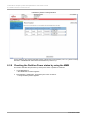
Checking the Partition Power status by using the MMB .................................................................................................... 161
8.3
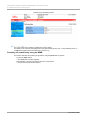
Scheduled operations............................................................................................................................................................... 163
8.3.1
Powering on a partition by scheduled operation ................................................................................................................ 163
8.3.2
Power off a Partition by scheduled operation ..................................................................................................................... 164
8.3.3
Relation of scheduled operation and power restoration function ...................................................................................... 164
8.3.4
Scheduled operation support conditions ............................................................................................................................ 164
8.4
Automatic Partition Restart Conditions .................................................................................................................................... 165
8.4.1
Setting automatic partition restart conditions ...................................................................................................................... 165
8.5
Power Restoration .................................................................................................................................................................... 167
8.5.1
Settings for Power Restoration............................................................................................................................................ 167
8.6
Remote shutdown (Windows).................................................................................................................................................. 167
8.6.1
Prerequisites for remote shutdown ..................................................................................................................................... 167
8.6.2
How to use remote shutdown ............................................................................................................................................. 168
CHAPTER 9
Configuration and Status Checking (Contents, Methods, and Procedures)................................................................ 169
9.1
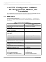
MMB Web-UI ............................................................................................................................................................................ 169
9.2
MMB CLI ................................................................................................................................................................................... 170
9.3
UEFI .......................................................................................................................................................................................... 171
9.4
ServerView Suite ...................................................................................................................................................................... 171
CHAPTER 10
Error Notification and Maintenance (Contents, Methods, and Procedures) ........................................................... 172
10.1
Maintenance ............................................................................................................................................................................. 172
10.1.1
Maintenance using the MMB ......................................................................................................................................... 172
10.1.2
Maintenance method ...................................................................................................................................................... 172
10.1.3
Maintenance modes ....................................................................................................................................................... 172
10.1.4
Maintenance of the MMB ............................................................................................................................................... 173
10.1.5
Maintenance of the PCI_BOX(PEXU)........................................................................................................................... 173
10.1.6
Maintenance policy/preventive maintenance ................................................................................................................ 174
10.1.7
REMCS service overview............................................................................................................................................... 174
10.1.8
REMCS linkage............................................................................................................................................................... 174
10.2
Troubleshooting ........................................................................................................................................................................ 175
10.2.1
Troubleshooting overview............................................................................................................................................... 175
10.2.2
Items to confirm before contacting a sales representative............................................................................................ 177
10.2.3
Sales representative (contact) ........................................................................................................................................ 177
10.2.4
Finding out about abnormal conditions .......................................................................................................................... 178
10.2.5
Investigating abnormal conditions .................................................................................................................................. 180
10.2.6
Checking into errors in detail .......................................................................................................................................... 183
10.2.7
Problems related to the main unit or a PCI_Box ........................................................................................................... 184
10.2.8
MMB-related problems ................................................................................................................................................... 184
xiv
C122-E175-01EN
Preface
10.2.9
Problems with partition operations ................................................................................................................................. 185
10.3
Notes on Troubleshooting ........................................................................................................................................................ 185
10.4
Collecting Maintenance Data ................................................................................................................................................... 185
10.4.1
Logs that can be collected by the MMB......................................................................................................................... 185
10.4.2
Collecting data for investigation (Windows) ................................................................................................................... 190
10.4.3
Setting up the dump environment (Windows) ............................................................................................................... 191
10.4.4
Acquiring data for investigation (RHEL) ......................................................................................................................... 197
10.4.5
sadump............................................................................................................................................................................ 198
10.5
Configuring and Checking Log Information............................................................................................................................. 198
10.5.1
List of log information ...................................................................................................................................................... 198
10.6
Firmware Updates .................................................................................................................................................................... 199
10.6.1
Notes on updating firmware............................................................................................................................................ 199
Appendix A Functions Provided by the PRIMEQUEST 2000 Series ....................................................................................................... 200
A.1
Function List .............................................................................................................................................................................. 200
A.1.1
Action.................................................................................................................................................................................... 200
A.1.2
Operation.............................................................................................................................................................................. 200
A.1.3
Monitoring and reporting functions...................................................................................................................................... 201
A.1.4
Maintenance......................................................................................................................................................................... 202
A.1.5
Redundancy functions ......................................................................................................................................................... 203
A.1.6
External linkage functions.................................................................................................................................................... 203
A.1.7
Security functions ................................................................................................................................................................. 203
A.2
Correspondence between Functions and Interfaces.............................................................................................................. 204
A.2.1
System information display.................................................................................................................................................. 204
A.2.2
System settings.................................................................................................................................................................... 204
A.2.3
System operation ................................................................................................................................................................. 204
A.2.4
Hardware status display ...................................................................................................................................................... 204
A.2.5
Display of partition configuration information and partition status...................................................................................... 205
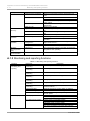
A.2.6 Partition configuration and operation setting ................................................................................................................................. 205
A.2.7 Partition operation........................................................................................................................................................................... 205
A.2.8 Partition power control .................................................................................................................................................................... 206
A.2.9 OS boot settings ............................................................................................................................................................................. 206
A.2.10 MMB user account control ........................................................................................................................................................... 206
A.2.11 Server management network settings ........................................................................................................................................ 206
A.2.12 Maintenance ................................................................................................................................................................................. 207
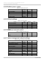
A.3
Management Network Specifications ...................................................................................................................................... 207
Appendix B Physical Mounting Locations and Port Numbers ................................................................................................................... 209
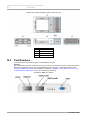
B.1
Physical Mounting Locations of Components......................................................................................................................... 209
B.2
Port Numbers............................................................................................................................................................................ 211
Appendix C Lists of External Interfaces Physical ....................................................................................................................................... 213
C.1
List of External System Interfaces............................................................................................................................................ 213
C.2
List of External MMB Interfaces ............................................................................................................................................... 213
Appendix D Physical Locations and BUS Numbers of Built-in I/O, and PCI Slot Mounting Locations and Slot Numbers .................... 214
D.1
Physical Locations and BUS Numbers of Internal I/O Controllers of the PRIMEQUEST 2000 Series ............................... 214
Correspondence between PCI Slot Mounting Locations and Slot Numbers ........................................................................ 214
D.2
Appendix E PRIMEQUEST 2000 Series Cabinets (Link) ......................................................................................................................... 217
Appendix F Status Checks with LEDs ........................................................................................................................................................ 218
F.1.
LED Type .................................................................................................................................................................................. 218
F1.1 Power LED, Alarm LED, and Location LED............................................................................................................................... 218
F.1.2
PSU ...................................................................................................................................................................................... 218
F.1.3
FANU.................................................................................................................................................................................... 219
F.1.4
SB ......................................................................................................................................................................................... 219
F.1.5
IOU ....................................................................................................................................................................................... 219
F.1.6
PCI Express slot of IOU....................................................................................................................................................... 220
F.1.7
DU......................................................................................................................................................................................... 220
F.1.8
HDD/SSD............................................................................................................................................................................. 220
xv
C122-E175-01EN
Preface
F.1.9
MMB ..................................................................................................................................................................................... 221
F.1.10
LAN .................................................................................................................................................................................. 221
F.1.11
OPL.................................................................................................................................................................................. 222
F.1.12
PCI_Box .......................................................................................................................................................................... 222
F.1.13
PCI Express slot in PCI_Box.......................................................................................................................................... 222
F.1.14
IO_PSU ........................................................................................................................................................................... 223
F.1.15
IO_FAN............................................................................................................................................................................ 223
F.2
LED Mounting Locations .......................................................................................................................................................... 223
F.3
LED list ...................................................................................................................................................................................... 225
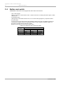
F.4
Button and switch...................................................................................................................................................................... 228
Appendix G Component Mounting Conditions........................................................................................................................................... 229
G.1
CPU ........................................................................................................................................................................................... 229
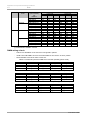
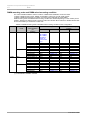
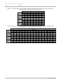
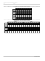
G.2
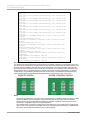
DIMM......................................................................................................................................................................................... 229
G.3
Configuration when using 100 V PSU ..................................................................................................................................... 237
G.4
Available internal I/O ports........................................................................................................................................................ 237
G.5
Legacy BIOS Compatibility (CSM) .......................................................................................................................................... 237
G.6
Rack Mounting .......................................................................................................................................................................... 237
G.7
Installation Environment ........................................................................................................................................................... 237
G.8
NIC (Network Interface Card)................................................................................................................................................... 237
Appendix H Tree Structure of the MIB Provided with the PRIMEQUEST 2000 Series........................................................................... 239
H.1
MIB Tree Structure ................................................................................................................................................................... 239
H.2
MIB File Contents ..................................................................................................................................................................... 240
Appendix I Windows Shutdown Settings .................................................................................................................................................... 241
I.1
Shutdown From MMB Web-UI ..................................................................................................................................................... 241
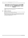
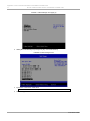
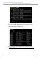
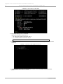
Appendix J How to Confirm Firmware of SAS RAID Controller Card ....................................................................................................... 242
J.1
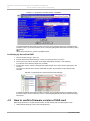
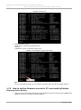
How to confirm firmware version of SAS RAID controller card .............................................................................................. 242
J.2
How to confirm firmware version of SAS card......................................................................................................................... 247
J.3
How to confirm firmware version and UEFI driver version of FC card ................................................................................... 250
J.3.1
How to confirm firmware version for FC card made by Qlogic .......................................................................................... 251
J.3.2
How to confirm firmware version for FC card made by Emulex........................................................................................ 254
Appendix K Software (Link) ......................................................................................................................................................................... 259
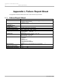
Appendix L Failure Report Sheet ................................................................................................................................................................ 260
L.1
Failure Report Sheet................................................................................................................................................................. 260
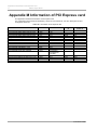
Appendix M Information of PCI Express card............................................................................................................................................. 261
xvi
C122-E175-01EN
Preface
Figures
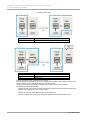
FIGURE 1.1 External network configuration............................................................................................................................................1
FIGURE 1.2 External network functions ..................................................................................................................................................2
FIGURE 1.3 Management LAN configuration.........................................................................................................................................6
FIGURE 1.4 Maintenance LAN and REMCS LAN of the MMB ......................................................................................................... 11
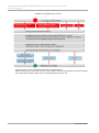
FIGURE 1.5 Connection configuration for video redirection ................................................................................................................ 14
FIGURE 1.6 Operating sequence of video redirection......................................................................................................................... 15
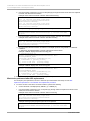
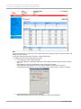
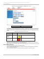
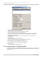
FIGURE 1.7 [Video Redirection] window.............................................................................................................................................. 15
FIGURE 1.8 Message of requesting access to Virtual Console in second terminal PC .................................................................... 19
FIGURE 1.9 Popup window of [Virtual Console Sharing Privileges]................................................................................................... 19
FIGURE 1.10 Popup for [Allow Virtual Console] in first terminal PC ................................................................................................... 19
FIGURE 1.11 Popup for TIMEOUT in first terminal PC ....................................................................................................................... 19
FIGURE 1.12 Popup for [Allow Virtual Console] in second terminal PC............................................................................................. 19
FIGURE 1.13 Popup for [Allow only video] in second terminal PC ..................................................................................................... 20
FIGURE 1.14 Popup for [Deny Access] in second terminal PC.......................................................................................................... 20
FIGURE 1.15 Popup for TIMEOUT in first terminal PC ....................................................................................................................... 20
FIGURE 1.16 Popup for reaching maximum number of connection in second terminal PC............................................................. 20
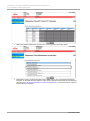
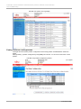
FIGURE 1.17 Example of setting partition #3 (1) ................................................................................................................................. 21
FIGURE 1.18 Example of setting partition #3 (2) ................................................................................................................................. 21
FIGURE 1.19 Forced disconnection of console redirection (1) ........................................................................................................... 22
FIGURE 1.20 Forced disconnection of console redirection (2) ........................................................................................................... 22
FIGURE 1.21 Configuration of virtual media connection ..................................................................................................................... 23
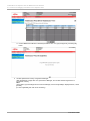
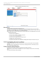
FIGURE 1.22 [Virtual Media] window (1) .............................................................................................................................................. 24
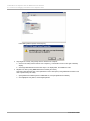
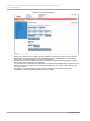
FIGURE 1.23 Image file selection window ........................................................................................................................................... 25
FIGURE 1.24 [Virtual Media] window (2) .............................................................................................................................................. 26
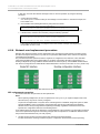
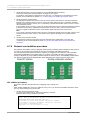
FIGURE 3.1 Conceptual diagram of the partitioning function (PRIMEQUEST 2400E)..................................................................... 29
FIGURE 3.2 Conceptual diagram of the partitioning function (PRIMEQUEST 2800E)..................................................................... 30
FIGURE 3.3 SB hotadd ......................................................................................................................................................................... 32
FIGURE 3.4 SB Hot remove (Disconnecting a faulty SB) ................................................................................................................... 32
FIGURE 3.5 IOU Hot add ...................................................................................................................................................................... 33
FIGURE 3.6 IOU hot remove (removal of failed IOU).......................................................................................................................... 33
FIGURE 3.7 Example 1-a. Example where two SBs are set as Reserved SBs in two partitions (when SB #0 and SB #1 have
simultaneously failed) ..................................................................................................................................................................... 38
FIGURE 3.8 Example 1-b.Example when one SB is set as the Reserved SB in two partitions (SB #0 and SB #2 have
simultaneously failed) ..................................................................................................................................................................... 39
FIGURE 3.9 Example 3. Example when multiple free SB (#2,#3) is set as Reserved SBs in Partition #0..................................... 39
FIGURE 3.10 Example 4. where Reserved SBs (#1, #2, #3) of Partition #0 belong to other partitions............................................ 40
FIGURE 3.11 Example 5. Example where the Reserved SBs (#1,#2,#3) of Partition #0 belong to other partitions................... 40
FIGURE 3.12 Example 6. Example where a Reserved SB has been set in SB #0 (When the Home SB has failed)..................... 41
FIGURE 3.13 Example 7. Example when SB #0 is set as the Reserved SB (when an SB other than the Home SB fails) ........... 41
FIGURE 3.14 Status when there is an error in the memory (mirror maintenance mode).................................................................. 45
FIGURE 3.15 Status when the error had occurred in the system was restarted (mirror maintenance mode) ................................. 45
FIGURE 3.16 Status when there error has occurred in the memory (memory capacity maintenance mode) ................................. 46
FIGURE 3.17 Status when an error has occurred in the memory (memory capacity maintenance mode) ..................................... 46
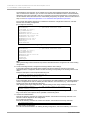
FIGURE 4.1 [Mode] window (Dynamic Reconfiguration) .................................................................................................................... 58
FIGURE 4.2 Single NIC interface and bonding configuration interface............................................................................................... 90
FIGURE 4.3 Example of single NIC interface....................................................................................................................................... 97
FIGURE 4.4 Single NIC interface and bonding configuration interface............................................................................................. 106
FIGURE 4.5 Single NIC interface and bonding configuration interface............................................................................................. 111
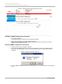
FIGURE 7.1 [Backup BIOS Configuration] window ........................................................................................................................... 154
FIGURE 7.2 [Restore BIOS Configuration] window........................................................................................................................... 155
xvii
C122-E175-01EN
Preface
FIGURE 7.3 [Restore BIOS Configuration] window (partition selection)........................................................................................... 155
FIGURE 7.4 [Backup/Restore MMB Configuration] window ............................................................................................................. 156
FIGURE 7.5 Restore confirmation dialog box .................................................................................................................................... 156
FIGURE 8.1 [System Power Control] window.................................................................................................................................... 157
FIGURE 8.2 [Power Control] window ................................................................................................................................................. 160
FIGURE 8.3 [Power Control] Window................................................................................................................................................. 161
FIGURE 8.4 [Information] window....................................................................................................................................................... 162
FIGURE 8.5 [Power Control] window ................................................................................................................................................. 163
FIGURE 8.6 [ASR (Automatic Server Restart) Control] window ....................................................................................................... 166
Figure 8.7 Simplified help for the shutdown command ...................................................................................................................... 168
FIGURE 10.1 REMCS linkage ............................................................................................................................................................ 175
FIGURE 10.2 Troubleshooting overview ............................................................................................................................................ 176
FIGURE 10.3 Label location................................................................................................................................................................ 177
FIGURE 10.4 Alarm LED on the front panel of the device ................................................................................................................ 178
FIGURE 10.5 System status display in the MMB Web-UI window................................................................................................... 179
FIGURE 10.6 Alarm E-Mail settings window...................................................................................................................................... 180
FIGURE 10.7 System status display................................................................................................................................................... 181
FIGURE 10.8 System event log display ............................................................................................................................................. 182
FIGURE 10.9 [Partition Configuration] window .................................................................................................................................. 182
FIGURE 10.10 [Partition Event Log] window...................................................................................................................................... 183
FIGURE 10.11 [System Event Log] window in PRIMEQUEST 2400E and 2800E......................................................................... 186
FIGURE 10.12 [System Event log] window in PRIMEQUEST 2800B ............................................................................................. 186
FIGURE 10.13 [System Event Log Filtering Condition] window in PRIMEQUEST 2400E and 2800E.......................................... 187
FIGURE 10.14 [System Event Log Filtering Condition] window in PRIMEQUEST 2800B ............................................................. 188
FIGURE 10.15 [System Event Log (Detail)] window.......................................................................................................................... 189
FIGURE 10.16 [Startup and Recovery] dialog box ............................................................................................................................ 193
FIGURE 10.17 [Advanced] tab of the dialog box ............................................................................................................................... 194
FIGURE 10.18 [Virtual Memory] dialog box ....................................................................................................................................... 195
FIGURE 10.19 Advanced options dialog box..................................................................................................................................... 196
FIGURE 10.20 [Virtual Memory] dialog box ....................................................................................................................................... 197
FIGURE B.1 Physical mounting locations in the PRIMEQUEST 2400E.......................................................................................... 209
FIGURE B.2 Physical mounting locations in the PRIMEQUEST 2800E/2800B.............................................................................. 210
FIGURE B.3 Physical mounting locations in the DU.......................................................................................................................... 210
FIGURE B.4 Physical mounting locations in the PCI_Box ................................................................................................................ 211
FIGURE B.5 MMB port numbers ........................................................................................................................................................ 211
FIGURE B.6 IOU_1GbE port numbers .............................................................................................................................................. 212
FIGURE B.7 IOU_10GbE port numbers ............................................................................................................................................ 212
FIGURE F.1 LED mounting locations on components equipped with LAN ports ............................................................................ 223
FIGURE F.2 Mounting locations of PSU and FANU.......................................................................................................................... 224
FIGURE F.3 MMB LED mounting locations ....................................................................................................................................... 224
FIGURE F.4 DU LED mounting locations .......................................................................................................................................... 224
FIGURE F.5 System LED mounting locations ................................................................................................................................... 224
FIGURE F.6 PCI_Box LED mounting locations ................................................................................................................................. 224
FIGURE H.1 MIB tree structure........................................................................................................................................................... 240
FIGURE J.1 Boot Manager front page (1) .......................................................................................................................................... 242
FIGURE J.2 Boot Manager front page (2) .......................................................................................................................................... 243
FIGURE J.3 Boot Manager menu....................................................................................................................................................... 243
FIGURE J.4 Driver list .......................................................................................................................................................................... 244
FIGURE J.5 drivers command of UEFI Shell ..................................................................................................................................... 244
FIGURE J.6 dh command of UEFI Shell ............................................................................................................................................ 245
FIGURE J.7 selection of EFI WebBIOS / EFI CLI.............................................................................................................................. 245
FIGURE J.8 [Adapter Selection] window of WebBIOS (1) ................................................................................................................ 246
FIGURE J.9 [Adapter Selection] window of WebBIOS (2) ................................................................................................................ 246
FIGURE J.10 [HOME] window of WebBIOS...................................................................................................................................... 246
FIGURE J.11 [Controller Properties] window of WebBIOS ............................................................................................................... 247
xviii
C122-E175-01EN
Preface
FIGURE J.12 [General] tab in the ServiewView RAID Manager....................................................................................................... 247
FIGURE J.13 Menu window................................................................................................................................................................ 248
FIGURE J.14 Device List in [Device Manager] window..................................................................................................................... 248
FIGURE J.15 EFI driver version in [LSI SAS2 MPT Controller Configuration] ................................................................................. 249
FIGURE J.16 [Configuration Options] window ................................................................................................................................... 249
FIGURE J.17 [Controller Management] window ................................................................................................................................ 250
FIGURE J.18 [View Controller Properties] window ............................................................................................................................ 250
FIGURE J.19 FUJITSU logo window.................................................................................................................................................. 251
FIGURE J.20 Confirmation of UEFI driver version and firmware version ......................................................................................... 251
FIGURE J.21 Boot Manager front page (1) ........................................................................................................................................ 252
FIGURE J.22 Boot Manager front page (2) ........................................................................................................................................ 252
FIGURE J.23 Boot Manager menu..................................................................................................................................................... 253
FIGURE J.24 UEFI Shell ..................................................................................................................................................................... 253
FIGURE J.25 Driver list........................................................................................................................................................................ 254
FIGURE J.26 Confirmation of UEFI driver version............................................................................................................................. 254
FIGURE J.27 Boot Manager front page (1) ........................................................................................................................................ 255
FIGURE J.28 Boot Manager front page (2) ........................................................................................................................................ 255
FIGURE J.29 [Device Manager] window............................................................................................................................................ 256
FIGURE J.30 [Emulex configuration Utility] window........................................................................................................................... 256
FIGURE J.31 [Adapter Selection] window (HBA list) ......................................................................................................................... 257
FIGURE J.32 [Emulex Adapter Configuration Main Menu] window ................................................................................................. 257
FIGURE J.33 [Controller Information] window.................................................................................................................................... 258
xix
C122-E175-01EN
Preface
Tables
TABLE 1.1 External network names and functions.................................................................................................................................1
TABLE 1.2 IP addresses for the PRIMEQUEST 2000 series server (IP addresses set from the MMB) ............................................3
TABLE 1.3 IP addresses for the PRIMEQUEST 2000 series server (set from the operating system in a partition) ...........................4
TABLE 1.4 Restrictions on the management LAN..................................................................................................................................6
TABLE 1.5 Parts of the management LAN configuration .......................................................................................................................7
TABLE 1.6 Maintenance LAN/REMCS LAN........................................................................................................................................ 11
TABLE 1.7 Maximum number of connections using the remote operation function .......................................................................... 13
TABLE 1.8 List of video redirection function ......................................................................................................................................... 13
TABLE 1.9 Menu Bar in [Video redirection] window ............................................................................................................................ 15
TABLE 1.10 Tool Bar menu in [Video redirection] window .................................................................................................................. 18
TABLE 1.11 Status Bar in [Video redirection] window ......................................................................................................................... 18
TABLE 1.12 Buttons in [Virtual Media] window .................................................................................................................................... 24
TABLE 1.13 Items in image file selection window ................................................................................................................................ 25
TABLE 3.1 Configuration rules for partition (components)................................................................................................................... 28
TABLE 3.2 Applicable criteria ................................................................................................................................................................ 33
TABLE 3.3 DR supported list................................................................................................................................................................. 34
TABLE 3.4 Memory Operation Mode before and after Reserved SB switching, when a partition is configured from one SB. ....... 37
TABLE 3.5 Operational restrictions when switching to a Reserved SB .............................................................................................. 43
TABLE 3.6 Overview of Memory Operation Modes............................................................................................................................. 43
TABLE 3.7 Memory Mirror Mode .......................................................................................................................................................... 44
TABLE 3.8 Memory mirror group .......................................................................................................................................................... 44
TABLE 3.9 Combination of the memory mirror status and the failed DIMM (Non Mirror).................................................................. 46
TABLE 3.10 Replaceable components and replacement conditions.................................................................................................. 48
TABLE 3.11 Replacement notification messages RAS support service (UPS) ................................................................................. 49
TABLE 3.12 Expandable components ................................................................................................................................................. 51
TABLE 3.13 Partition setting (before switching) ................................................................................................................................... 55
TABLE 3.14 Reserved SB setting (before switching)........................................................................................................................... 55
TABLE 3.15 Partition status transition................................................................................................................................................... 56
TABLE 3.16 Description of partition status transition............................................................................................................................ 56
TABLE 3.17 Partition setting (after switching)....................................................................................................................................... 56
TABLE 3.18 Reserved SB setting (after switching).............................................................................................................................. 56
TABLE 3.19 Example of Home SB No. replacement .......................................................................................................................... 56
TABLE 3.20 Relationship between LSB No. and Socket No .............................................................................................................. 57
TABLE 4.1 Correspondence between bus addresses and interface names ..................................................................................... 66
TABLE 4.2 Hardware address description examples .......................................................................................................................... 67
TABLE 4.3 Example of interface information about interfaces after replacement .............................................................................. 70
TABLE 4.4 Correspondence between bus addresses and interface names ..................................................................................... 77
TABLE 4.5 Hardware address description examples .......................................................................................................................... 78
TABLE 4.6 Correspondence between bus addresses and interface names ..................................................................................... 91
TABLE 4.7 Hardware address description examples .......................................................................................................................... 92
TABLE 4.8 Example of interface information about the replacement NIC.......................................................................................... 94
TABLE 4.9 Example of entered values corresponding to the interface names before and after NIC replacement ......................... 95
Table4.10 Confirmation of interface names ......................................................................................................................................... 96
TABLE 8.1 Power on method and power on unit............................................................................................................................... 158
TABLE 8.2 Power on method and Power on unit .............................................................................................................................. 159
TABLE 8.3 Privilege for power on and power off................................................................................................................................ 159
TABLE 8.4 Privilege for power on and power off (continued) ............................................................................................................ 159
TABLE 8.5 Relationship between scheduled operation and partition power restoration mode....................................................... 164
TABLE 8.6 Power on/off ...................................................................................................................................................................... 164
TABLE 8.7 [ASR Control] window display / setting items .................................................................................................................. 166
TABLE 8.8 Power Restoration Policy ................................................................................................................................................. 167
xx
C122-E175-01EN
Preface
TABLE 9.1 Functions provided by the MMB Web-UI ........................................................................................................................ 169
TABLE 9.2 Functions provided by the MMB CLI ............................................................................................................................... 171
TABLE 9.3 Functions provided by the UEFI....................................................................................................................................... 171
TABLE 10.1 Maintenance modes ....................................................................................................................................................... 173
TABLE 10.2 Maintenance mode functions ......................................................................................................................................... 173
TABLE 10.3 Icons indicating the system status ................................................................................................................................. 179
TABLE 10.4 System problems and memory dump collection........................................................................................................... 185
TABLE 10.5 Setting and display items in the [System Event Log Filtering Condition] window........................................................ 188
TABLE 10.6 Setting and display items in the [System Event Log (Detail)] window.......................................................................... 190
TABLE 10.7 Memory dump types and sizes...................................................................................................................................... 191
TABLE A.1 Action ................................................................................................................................................................................ 200
TABLE A.2 Operations ........................................................................................................................................................................ 200
TABLE A.3 Monitoring and reporting functions .................................................................................................................................. 201
TABLE A.4 Maintenance functions ..................................................................................................................................................... 202
TABLE A.5 Redundancy functions ..................................................................................................................................................... 203
TABLE A.6 External linkage functions ................................................................................................................................................ 203
TABLE A.7 Security functions ............................................................................................................................................................. 203
TABLE A.8 System information display .............................................................................................................................................. 204
TABLE A.9 System settings ................................................................................................................................................................ 204
TABLE A.10 System operation ........................................................................................................................................................... 204
TABLE A.11 Hardware status display................................................................................................................................................. 204
TABLE A.12 Display of partition configuration information and partition status ................................................................................ 205
TABLE A.13 Partition configuration and operation setting ................................................................................................................. 205
TABLE A.14 Partition operation........................................................................................................................................................... 205
TABLE A.15 Partition power control.................................................................................................................................................... 206
TABLE A.16 OS boot settings ............................................................................................................................................................. 206
TABLE A.17 MMB user account control ............................................................................................................................................. 206
TABLE A.18 Server management network settings .......................................................................................................................... 206
TABLE A.19 Maintenance ................................................................................................................................................................... 207
TABLE A.20 Management network specifications............................................................................................................................. 207
TABLE A.21 Management network specifications ............................................................................................................................ 208
TABLE C.1 External system interfaces............................................................................................................................................... 213
TABLE C.2 External MMB interfaces.................................................................................................................................................. 213
TABLE D.1 physical locations of SB internal I/O controllers and BUS numbers .............................................................................. 214
TABLE D.2 Correspondence between PCI Slot Mounting Locations and Slot Numbers................................................................ 214
TABLE F.1 Power LED, Alarm LED, and Location LED ................................................................................................................... 218
TABLE F.2 PSU LED........................................................................................................................................................................... 218
TABLE F.3 Power status and PSU LED display................................................................................................................................ 218
TABLE F.4 FAN LED........................................................................................................................................................................... 219
TABLE F.5 Power status and FANU LED display ............................................................................................................................. 219
TABLE F.6 SB LED ............................................................................................................................................................................. 219
TABLE F.7 SB status and SB LED display ........................................................................................................................................ 219
TABLE F.8 IOU LED............................................................................................................................................................................ 220
TABLE F.9 IOU status and IOU LED display ..................................................................................................................................... 220
TABLE F.10 IOU LED.......................................................................................................................................................................... 220
TABLE F.11 IOU status and IOU LED display ................................................................................................................................... 220
TABLE F.12 HDD/SSD LED ............................................................................................................................................................... 220
TABLE F.13 HDD/SSD status and LED display ................................................................................................................................ 220
TABLE F.14 MMB LED ....................................................................................................................................................................... 221
TABLE F.15 MMB (device) status and LED display .......................................................................................................................... 221
TABLE F.16 LAN LEDs ....................................................................................................................................................................... 221
TABLE F.17 LAN LED and Linkup Speed ......................................................................................................................................... 221
TABLE F.18 OPL LED......................................................................................................................................................................... 222
TABLE F.19 System status and LED display..................................................................................................................................... 222
TABLE F.20 PCI_Box LED ................................................................................................................................................................. 222
xxi
C122-E175-01EN
Preface
TABLE F.21 PCI_Box status and PCI_Box LED display .................................................................................................................. 222
TABLE F.22 PCI Express card status and LED display .................................................................................................................... 222
TABLE F.23 IO_PSU LED .................................................................................................................................................................. 223
TABLE F.24 IO_PSU status and LED display ................................................................................................................................... 223
TABLE F.25 IO_FAN LED................................................................................................................................................................... 223
TABLE F.26 IO_FAN status and LED display.................................................................................................................................... 223
TABLE F.27 LED list (1/3).................................................................................................................................................................... 225
TABLE F.28 LED list (2/3).................................................................................................................................................................... 226
TABLE F.29 LED list (3/3).................................................................................................................................................................... 227
TABLE F.30 Usable PCI_Box number and models........................................................................................................................... 228
TABLE G.1 Numbers of SBs and CPUs per partition........................................................................................................................ 229
TABLE G.2 DIMM increment unit........................................................................................................................................................ 229
TABLE G.3 Relationship between DIMM size and mutual operability (within an SB) ...................................................................... 230
TABLE G.4 Relationship between DIMM size and mutual operability (within a partition) ................................................................ 230
TABLE G.5 Relationship between DIMM size and mutual operability (within a cabinet) ................................................................. 230
TABLE G.6 DIMM mounting order and DIMM mixed mounting condition in each configuration .................................................... 231
TABLE G.7 DIMM mounting order at 1CPU/1SB (*1) ....................................................................................................................... 232
TABLE G.8 DIMM mounting order at 2CPU/1SB (*1) ....................................................................................................................... 232
TABLE G.9 DIMM mixed mounting condition at 1CPU/1SB (*1) ...................................................................................................... 233
TABLE G.10 DIMM mixed mounting condition at 2CPU/1SB (*1).................................................................................................... 234
TABLE G.11 DIMM mounting order at 1CPU/1SB when a Partition includes 8 sockets with PCI Address Mode = Segment Mode,
or when DR is enabled in a Partition ........................................................................................................................................... 235
TABLE G.12 DIMM mounting order at 2CPU/1SB when a Partition includes 8 sockets with PCI Address Mode = Segment Mode,
or when DR is enabled in a Partition ........................................................................................................................................... 235
TABLE G.13 DIMM mixed mounting condition at 1CPU/1SB when a Partition includes 8 sockets with PCI Address Mode =
Segment Mode, or when DR is enabled in a Partition ............................................................................................................... 236
TABLE G.14 DIMM mixed mounting condition at 2CPU/1SB when a Partition includes 8 sockets with PCI Address Mode =
Segment Mode, or when DR is enabled in a Partition ............................................................................................................... 236
TABLE G.15 Available internal I/O ports and the quantities .............................................................................................................. 237
TABLE H.1 MIB file contents ............................................................................................................................................................... 240
TABLE M.1 Information of PCI Express card ..................................................................................................................................... 261
xxii
C122-E175-01EN
CHAPTER 1 Network Environment Setup and Tool Installation
1.1 External Network Configuration
CHAPTER 1 Network Environment Setup and
Tool Installation
This chapter describes the external network environment and management tool installation for the
PRIMEQUEST 2000 series. For an overview of the management tools used for the PRIMEQUEST 2000
series, see Chapter 8 Operations Management Tools in the PRIMEQUEST 2000 Series General Description
(C122-B022EN).
1.1
External Network Configuration
The following diagram shows the external network configuration for the PRIMEQUEST 2000 series.
FIGURE 1.1 External network configuration
No.
(1)
(2)
(3)
Description
SW redundancy
Redundancy by teaming (GLS or equivalent)
Disabled on the standby side
The following table lists the external networks. The letters A, B, and C correspond to those in FIGURE 1.1
External network configuration.
TABLE 1.1 External network names and functions
Letter
A
External network name
Management LAN
B
Maintenance LAN
-
1
Function
MMB Web-UI/CLI operations
Operations management server
Video redirection
PRIMECLUSTER linkage
Systemwalker linkage
ServerView linkage
REMCS connection
FST (CE terminal) connection
C122-E175-01EN
CHAPTER 1 Network Environment Setup and Tool Installation
1.1 External Network Configuration
Letter
C
External network name
Function
- REMCS connection
Operation LAN (production LAN)
For job operations
Connect a LAN cable for User Port and a LAN cable for REMCS Port to different HUB each other or divide
them by using VLAN.
The following diagram shows the functions of external networks for the PRIMEQUEST 2000 series.
FIGURE 1.2 External network functions
2
C122-E175-01EN
CHAPTER 1 Network Environment Setup and Tool Installation
1.2 How to Configure the External Networks (Management LAN/ Maintenance LAN/Production LAN)
1.2
How to Configure the External Networks (Management
LAN/ Maintenance LAN/Production LAN)
The PRIMEQUEST 2000 series server must be connected to the following three types of external networks.
The respective external networks are dedicated to security and load distribution. (See FIGURE 1.1 External
network configuration.)
-
Management LAN
-
Maintenance LAN
-
Production LAN
Note
Be sure to connect management LAN, production LAN and maintenance LAN to different subnet each other
This section describes the IP addresses for the PRIMEQUEST 2000 series server.
1.2.1 IP addresses used in the PRIMEQUEST 2000 series server
Each of the SB, IOU, and MMB units in the PRIMEQUEST 2000 series server has network interfaces. Each
port of these network interfaces must be assigned an IP address.
To the ports, assign IP addresses appropriate to the external network environment of the PRIMEQUEST
2000 series server.
The following describes the IP addresses assigned to the ports.
TABLE 1.2 IP addresses for the PRIMEQUEST 2000 series server (IP addresses set from the MMB) lists the
IP addresses that are set from the MMB. TABLE 1.3 IP addresses for the PRIMEQUEST 2000 series server
(set from the operating system in a partition) lists the IP addresses that are set from the operating system.
The IP addresses in TABLE 1.2 IP addresses for the PRIMEQUEST 2000 series server (IP addresses set
from the MMB) are assigned to the NICs (network interface controllers) on the MMBs. Each NIC is connected
to an SB or an external network port of the MMB through the switching hub on the MMB. The MMB firmware
uses the IP addresses.
The standard configuration has one MMB. For a dual MMB configuration, which has two MMBs, assign a
common virtual IP address to both MMBs. In addition to the virtual IP address, assign one physical IP
address to each MMB.
TABLE 1.2 IP addresses for the PRIMEQUEST 2000 series server (IP addresses set from the MMB)
Name
NIC
Type
IP address
Description
setting
method
- Management LAN IP address: MMB Virtual/Physical IP address
This IP address is used for communication when the MMB is connected to the management LAN. The
physical IP address is assigned to the NIC of the user port of each MMB, and the virtual IP address is
assigned commonly to the duplicated MMBs. The virtual IP address is used for access from PC etc. on the
management LAN. The virtual IP is inherited by an active MMB.
Virtual IP
MMB
Virtual IP
Set it from
The PC connected to the management LAN
Address
(common)
address
the MMB
uses this IP address to communicate (via the
CLI or MMB Web, telnet, etc.) with the (active) MMB. The
(*1)
Web-UI.
PC user need not be aware of which MMB is
active, MMB#0 or MMB#1.
MMB#0 IP
MMB#0 (*1)
Physical
Set it from
The PC connected to the management LAN
Address
IP address the MMB
uses this IP address to communicate with
CLI or MMB MMB#0. (*2)
Web-UI.
MMB#1 IP
MMB#1 (*1)
Physical
Set it from
The PC connected to the management LAN
Address
IP address the MMB
uses this IP address to communicate with
CLI or MMB MMB#1. (*2)
Web-UI.
- Maintenance LAN IP address: Maintenance IP address
This IP address is used for communication when the MMB is connected to the maintenance LAN.
Maintenance MMB
Physical IP Set it from
This IP address is used for communication
3
C122-E175-01EN
CHAPTER 1 Network Environment Setup and Tool Installation
1.2 How to Configure the External Networks (Management LAN/ Maintenance LAN/Production LAN)
Name
IP Address
NIC
(common)
Type
address
(*3)
IP address
setting
method
the MMB
CLI or MMB
Web-UI.
Description
with REMCS, without using the management
LAN. The MMB also uses the IP address to
communicate with the maintenance terminal
connected to the CE port.
- Internal LAN IP address: MMB-PCH IP Address
This is a dedicated IP address for MMB communication with SVS running on the operating system in each
partition. (*6)
Internal IP
MMB
Physical IP Set it from
This is a dedicated IP address for REMCS
Address
(common)
address
the MMB
option.
(*4)
(*3)
Web-UI.
- Console redirection IP address: Console Redirection IP Address
Console
BMC
Physical IP Set it from
This IP address is used to access the console
Redirection
address
the MMB
redirection function in each partition from the
IP Address
(*5)
Web-UI.
PC on the management LAN. An IP address
on the management LAN is assigned to each
partition.
*1 These three addresses must have the same subnet address.
*2 The server administrator need not be concerned with individual IP addresses specified for communication.
*3 The IP address is intended only for communication with the active MMB.
*4 It is connected to the communication of the Internal LAN, and is not connected to any external network.
The assigned IP address must be in a different subnet from the management LAN, maintenance LAN, or
production LAN. The default setting is 172.30.0.1/24, and it does not have to be changed unless it is in
conflict with another subnet.
*5 This IP address is to access the console redirection function provided by BMC. It accesses BMC from the
user port on the management LAN of MMB via the dedicated network for BMC-to-MMB communication
inside the cabinet.
MMB changes the local IP address of BMC to the IP address on the management LAN by NAT. From the
PC on the management LAN, the console redirection function of BMC is used via MMB.
*6 If Disable is set for this address, neither REMCS notification nor e-mail notification in case of panic.
Remarks
-
A separate subnet must be assigned to "Management LAN", "Maintenance LAN" (external network), and
"Internal LAN" (inside the cabinet LAN).
-
Since "3. Internal LAN" is closed to the outside of the cabinet, the same subnet as that for "Internal LAN"
in another cabinet can be used.
-
For the IP address to be assigned to "Console redirection", the same subnet as that assigned to "1.
Management LAN" must be used.
-
MMB uses the following subnets permanently for internal communication.
The following subnets cannot be specified:
127.1.1.0/24
127.1.2.0/24
127.1.3.0/24
The PCH on an SB in each partition has a 100 Mb Ethernet port connected with the PCH-to-MMB
communication LAN inside the cabinet. The operating system assigns the IP address of the 100 Mb Ethernet
port.
TABLE 1.3 IP addresses for the PRIMEQUEST 2000 series server (set from the operating system in a partition)
LAN port
100 MbE port on
SB (NIC in PCH)
(*1)
LAN port in IOU
Network card
IP address setting
method
Set it from the OS in
each partition.
Set it from the OS in
each partition.
Set it from the OS in
Description
100 MbE port connected to the Internal LAN. This IP address
and the IP address of the Internal LAN IP Address in TABLE 1.2
IP addresses for the PRIMEQUEST 2000 series server (IP
addresses set from the MMB) IP addresses for the
PRIMEQUEST 2000 series server (IP addresses set from the
MMB) are in the same subnet. An IP address must be assigned
to each partition.
This depends on the partition configuration.
Each port is connected to a network outside the cabinet. The
4
C122-E175-01EN
CHAPTER 1 Network Environment Setup and Tool Installation
1.3 Management LAN
LAN port
mounted in PCI
Express slot in IOU
or PCI_Box.
IP address setting
method
each partition.
Description
ports in the relevant partition must have IP addresses. (Assign
IP addresses to the ports used for actual operation.)
*1 The default IP address (172.30.0.[partition number + 2]) is assigned during installation of SVS. The default
IP address can be used unless it is in conflict with the one in the other subnet.
Remarks
1.3
-
The NIC in PCH on the Home SB is used as the NIC of the partition for internal LAN. The network device
name is not defined uniquely. The NIC in PCH on the Home SB is searched by using the bus number,
device number, and function number assigned to NIC.
-
Even if the Home SB is switched by Reserved SB function, Internal LAN is kept communicating. MMB
writes over the MAC address of the NIC in PCH on the Home SB and keeps the same MAC address as
that before the SB was switched.
For this MAC address, a unique value is assigned to each partition and managed as system FRU
information so that it is unique per cabinet.
-
Only “AutoNego” is supported as setting of GbE port speed in IOU_10GbE.
Management LAN
This section describes the configuration of the management LAN for the PRIMEQUEST 2000 series.
1.3.1 Overview of the management LAN
The MMB has two GbE LAN ports (USER ports) dedicated to the management LAN.
The partition side can use the LAN port on the IOU as a management LAN port. The PCL communications/
operations management server is connected to the MMB USER port through an external switch.
IP addresses of the management LAN (MMB)
Each MMB has one physical IP address for the management interface of the PRIMEQUEST 2000 series
server. In addition to that, the primary MMB shares a common virtual IP address in the system. You can set
these IP addresses from the MMB Web-UI or CLI.
Remarks
Virtual LAN interfaces are used for the management LAN interfaces. The physical LAN interfaces are used
only for recognizing the respective MMBs.
The physical LAN interface of each MMB makes redundant the two User ports located in that MMB, using the
interface redundancy function, to create a single LAN interface.
Virtual LAN interfaces handle the common virtual IP address shared between the two redundant MMBs. The
Virtual LAN interfaces share the physical LAN interfaces, which are ports on the two MMBs. The ports are
treated as valid channels on the active MMB. Any switching of the active MMB causes switching of the
corresponding connections to Virtual LAN channels.
The following shows a management LAN configuration diagram. The IP addresses are examples. The
addresses depend on the settings.
5
C122-E175-01EN
CHAPTER 1 Network Environment Setup and Tool Installation
1.3 Management LAN
FIGURE 1.3 Management LAN configuration
No.
Description
(1)
Physical LAN IP example (MMB #0): 10.20.30.101
(2)
Physical LAN IP example (MMB #1): 10.20.30.102
(3)
Virtual LAN IP example: 10.20.30.100
If either USER port fails, the interface redundancy function switches to the other port in the MMB to ensure
continuous service. If a failure occurs in the active MMB itself, the Virtual LAN channels become unusable.
Then, the standby MMB inherits the virtual IP address from the active MMB to ensure continuous service.
The following interfaces are available with a configured management LAN:
Interfaces available to the system administrator:
-
Web-UI interface using HTTP/HTTPS
-
CLI interface via telnet/SSH
-
Partition and console operations through the video redirection function
Interface available to system management software:
-
RMCP and RMCP + interface
Remarks
The restrictions on management LAN interfaces other than Virtual LAN channels are described below.
TABLE 1.4 Restrictions on the management LAN
Channel name
RMCP connection
Web-UI connection
CLI connection
(UDP)
(http/https)
(telnet/ssh)
Virtual LAN channel
Possible
Possible
Possible
Physical LAN channel (Active MMB)
Possible
Not possible
Possible
Physical LAN channel (Standby MMB) (*1)
Possible with
Possible with
restrictions (*2)(*3)
restrictions (*4)
Not possible
*1 Only PRIMEQUEST 2400E and 2800E can have two MMBs. PRIMQUEST 2800B can have only one MMB.
*2 The connection cannot send or receive data of over 4 Kbytes.
*3 The connection sends data to the active MMB, so adequate performance cannot be obtained.
*4 Only the following commands can be executed:
-
Set command
set active_mmb 0
-
Show commands
show active_mmb show
access_control show date
6
C122-E175-01EN
CHAPTER 1 Network Environment Setup and Tool Installation
1.3 Management LAN
show timezone show gateway show http
show http_port show https
show https_port show ssh
show ssh_port show telnet
show telnet_port show ip
show network show exit_code ping
who
netck arptbl netck arping netck ifconfig netck stat
show user_list help
show snmp sys_location
show snmp sys_contact
show snmp community
show snmp trap
show maintenance_ip
IP address of the management LAN (partition)
To the partition side, an IP address of the management LAN must be assigned to communicate with SVS
running on the operating system from the terminal on the management LAN. The IP address is assigned to
the LAN port on the IOU or the PCI_Box mounted on the network card. Also, for monitoring with SVOM, an IP
address must be assigned to the management LAN.
When it is linked with PRIMECLUSTER, the SVS on the partition side communicates with the user port of the
MMB via the management LAN. It also provides the function for monitoring the status of the cluster node and
the node switching function.
1.3.2 How to configure the management LAN
The network for MMB access from external terminals is the management LAN.
For management LAN-related settings for MMB access, use the CLI or the [Network Configuration] menu in
the Web-UI. For details on the network configuration, see 1.1 External Network Configuration.
The following lists the settings for the management LAN configuration. Only a user with Administrator
privileges can make management LAN-related settings.
TABLE 1.5 Parts of the management LAN configuration
Display/Setting item
Description
Network Interface: IP address and other settings for MMB access
Virtual IP Address
Virtual IP address. In a dual MMB configuration, the IP address is overtaken
during MMB switching.
Host Name/IP Address/Subnet Mask/Gateway Address
MMB#0 (MMB#1) IP Address
Physical IP address of MMB#0 (MMB#1). You set this IP address for MMB#0
(*1)
(MMB#1) mounted in the system.
Enable/Disable setting
Interface Name/IP Address/Subnet Mask/Gateway Address
DNS (optional)
Option. It specifies the IP address of the DNS server used. The default is
‘Disabled’. Enable/Disable setting
IP Address: DNS Server 1/DNS Server 2/DNS Server 3
Management LAN
Specifies duplication of the management LAN ports. The default is
‘Disabled’. (Only the ports on the #0 side are enabled.)
Enable/Disable setting
Maintenance IP Address
Specifies the REMCS/CE port. The default is ‘Disabled’. Enable/Disable
setting
IP Address/Subnet Mask/SMTP Address
Internal LAN IP Address
IP Address/Subnet Mask/Gateway Address
Specifies the NIC on the MMB of the Internal (PCH-to-MMB) LAN. The
default is Enable and the specified [IP Address] value. The MMB blocks
communication between partitions.
Management LAN Port Configuration: Management LAN port settings
Speed/Duplex for MMB#0
Specifies a Speed/Duplex value for the MMB#0 (MMB#1) LAN ports. Port:
(MMB#1) (*1)
USER Port, Maintenance Port
Setting value: Auto (default), 1G/Full, 100M/Full, 100M/Half, 10M/Full, 10M/
Half
The MMB USER port is duplicated.
The speed of 1 Gbps can be specified only for the USER ports. The possible
7
C122-E175-01EN
CHAPTER 1 Network Environment Setup and Tool Installation
1.3 Management LAN
Display/Setting item
Description
settings for the respective ports depend on the MMB hardware configuration.
Network Protocols: Network protocol settings
HTTP, HTTPS, telnet, SSH,
Specifies whether to enable or disable a protocol, the port number, and the
SNMP
Timeout time.
SNMP Configuration: SNMP-related settings
SNMP Community
Specifies SNMP System Information and Community/User values.
- System Information: Specifies System Location and System Contact
values for SNMP. It also displays the system name specified from
[System] - [System Information].
- Community: Can specify up to 16 Community/User items. Each
Community/User item includes the access-permitted IP address, SNMP
version, access permission, and authentication settings. For settings
specific to SNMP v3, use the SNMP v3 Configuration menu.
SNMP Trap
Specifies SNMP trap destinations.
You can set up to 16 destinations. Each trap destination item includes the
Community/User name, destination IP address, SNMP version, and
authentication level settings.
[Test Trap] button: Sends a test trap to the specified trap destination.
SNMP v3 Configuration: Settings specific to SNMP v3
Engine ID
Specifies the Engine ID.
- Enter the encryption hash function, authentication passphrase, and
encryption passphrase for users.
SSL: SSL settings
Create CSR
Creates a private key and a request for a signature (CSR: Certificate Signing
Request)
- SSL certificate status: Displays the current status of SSL certificate
installation.
- Key length: Length of the private key, 1024 bits or 2048 bits
- Entered information on the owner specified for the CSR
- Country, prefecture, city/town, organization, department, server, e-mail
address
- [Create CSR] button: Displays a confirmation dialog box. Clicking [OK]
creates a new private key and a request for a signature. After
completion, a dialog box appears. Clicking [OK] registers the private key
and causes a jump to the [Export Key/CSR] window. Clicking [Cancel]
gives an instruction to discard the created private key and CSR.
Export Key/CSR
Exports an MMB private key/CSR (backup).
- [Export Key] button: Exports a private key.
- [Export CSR] button: Exports a CSR.
Note
Clicking the [Export Key] button/ [Export CSR] button using FireFox 4 or later
flashes a save confirmation dialog box, resulting in the secret key not being
downloadable. Therefore, use Internet Explorer during [Export Key/Export
CSR] window manipulation.
Import Certificate
Imports a signed electronic certificate sent from a certificate authority. To
import a file, specify the file, and click the [Import] button.
Create Selfsigned Certificate
Creates a self-signed certificate.
- SSL certificate status: Displays the current status of self-signed
certificate installation.
- Term: Specifies the term of validity (number of days) of the self-signed
certificate.
- The other settings are the same as on the [Create CSR] window.
- [Create Selfsigned Certificate] button: Creates a self-signed certificate.
SSH: SSH settings
Create SSH Server Key
Creates an SSH server private key.
- SSH Server Key Status: Displays the status of SSH server key installation.
- [Create SSH Server Key] button: Creates a private key. After creation is
completed, a confirmation dialog box appears. Clicking [OK] installs the
created key. Clicking [Cancel] discards it.
8
C122-E175-01EN
CHAPTER 1 Network Environment Setup and Tool Installation
1.3 Management LAN
Display/Setting item
Description
Remote Server Management: User settings for remote control of the MMB via RMCP
- Use the [Edit User] button to select the user to be edited. The default settings for all users is [No Access]
and [Disable].
- You can edit the user name, password, permission, and status (Enable/Disable) in the [Edit User]
- To deny access to a user, set [No Access] for permission or [Disable] for [Status].
Access Control: Access control settings for network protocols
[Add Filter]/[Edit Filter]/
Adds, edits, or deletes a filter.
[Remove Filter] button
[Edit Filter] window
- Protocol: Select the target protocol (HTTP/HTTPS/telnet/SSH/SNMP).
- Access Control: Select [Enable] or [Disable].
- Disable: Denies access by any IP address.
- Enable: Permits access by only the specified IP addresses.
- IP Address/Subnet Mask: You can specify this item only if the [Access
Control] setting is [Enable]. The filtering permits access by only the IP
addresses specified here.
Alarm E-Mail: Settings for e-mail notification of an event
Alarm E-Mail
Used to select whether to send e-mail for the occurrence of an event
(Enable/ Disable).
From
Sender address
To
Destination address
SMTP Server
IP address or FQDN of the SMTP server
Subject
E-mail title
[Filter] button
Used to edit Alarm E-mail transmission filter settings. The occurrence of any
event specified in the filter settings is reported by e-mail. The default for
target events is all events.
- Severity: Target severity (Error/Warning/Info)
- Partition: Target partition
- Unit: Target unit
- Source: Target source (CPU/DIMM/Chipset/Voltage/Temperature/ Other)
[Test E-Mail] button
Sends test e-mail.
Video redirection/remote storage network settings
[Partition] - [Console
The video redirection/remote storage network relays traffic through the MMB,
Redirection Setup] menu
so the BMC IP address is not seen by users. Users access the system via
the management LAN of the MMB.
Here, specify the IP address used for access by the video redirection client
(Java applet). The MMB handles address conversion between the specified
address and BMC IP address.
*1 Only PRIMEQUEST 2400E and 2800E can have two MMBs. PRIMQUEST 2800B can have only one MMB.
The settings of the management LAN on the partition side are made on the operating system. These are
required to access SVS from a management PC on the management LAN. SVS also communicates with the
MMB via the management LAN to monitor and to switch cluster nodes in the PRIMECLUSTER linkage.
To the NIC to be used for the management LAN, the LAN port on IOU or the network card mounted in the
PCI_Box is assigned. Following is used for Management LAN:
-
Onboard LAN ports in IOU.
-
PCI express card in IOU or PCI_Box.
The subnet of the management LAN shares the virtual IP address and the physical address of the MMB,
which are specified by Web-UI/CLI on the MMB.
The management LAN and production LAN can be configured in the same subnet. In such case, an IP
address is assigned to both the management LAN and the production LAN on the partition connected to the
subnet of the LAN to which the MMB User Port is connected.
1.3.3 Redundant configuration of the management LAN
For the MMB, only MMB#0 is mounted as standard. By mounting MMB#1, the MMB can be redundant for
PRIMEQUEST 2400E and 2800E. MMB cannot be redundant for PRIMEQUEST 2800B. For PRIMEQUEST
2400E and 2800E, when the MMB detects an error in the MMB itself, it switches the active MMB so that
operations can continue. When the active MMB is switched, the virtual IP address is inherited by the MMB
that becomes active. Therefore, the administrator does not to need to consider which MMB is active.
9
C122-E175-01EN
CHAPTER 1 Network Environment Setup and Tool Installation
1.3 Management LAN
Because the MMB cannot recognize errors occurring in the path for accessing the MMB user port from the
management LAN, it is unable to recover from them by switching the active MMB. Therefore, two user ports
of the management LAN are mounted on the MMB. This redundant configuration enables recovery from
management LAN errors. The redundant configuration of the user port is disabled as standard, and only user
port #0 is enabled.
When the redundant configuration of the user port of the management LAN is enabled, the NICs on both user
port #0 and user port #1 are enabled. These two NICs appear as one virtual interface from external devices
because of the bonding function (each MMB has a physical address and a MAC address).
The MMB monitors errors of the management LAN (including connections to unit-external switches and LAN
cable disconnections). When it detects an error, it switches the duplicated NIC so that the monitoring
operation, which includes the Web-UI operations, can continue. The values of the physical IP address and
the MAC address of the MMB prior to switching are maintained.
To set up the management LAN in a redundant configuration, select [Network Configuration] - [Network
Interface] from the MMB Web-UI, and then set Enable for [Dualization] of [Maintenance LAN].
For the redundant configuration of the management LAN on the partition side, duplicate the NIC by teaming
with Linux Bonding driver, GLS or Intel PROSet.
When the MMB is duplicated, but the management LAN user port of the MMB is not duplicated, if an error
occurs on the management LAN, MMB access is disabled in PRIMEQUEST 2400E and 2800E. Because the
MMB does not recognize its error, it does not automatically switch the active MMB, and the virtual IP address
of the MMB cannot be switched to the available MMB. In such cases, the active MMB must be switched
manually. The procedure is described below for only PRIMEQUEST 2400E and 2800E.
-
(When MMB#0 is active, and MMB#1 is standby, an error occurs during an attempt by the management
LAN to access the user port on the MMB#0 side, and MMB#0 access is disabled)
1. Connect to the physical IP address of the management LAN user port on MMB#1 with telnet/ssh.
2. Execute the following command on MMB#1, and switch the active MMB to MMB#1.
> set active_mmb 1
3. The virtual IP address of the MMB is switched to MMB#1, and access is enabled with the virtual IP
address.
10
C122-E175-01EN
CHAPTER 1 Network Environment Setup and Tool Installation
1.4 Maintenance LAN/REMCS LAN
1.4
Maintenance LAN/REMCS LAN
The MMB provides the following LAN ports for maintenance purposes.
TABLE 1.6 Maintenance LAN/REMCS LAN
Port
Description
Remarks
CE LAN
FST (CE terminal) port for use in maintenance work
100Base-TX, RJ45
REMCS LAN
For a connection with the REMCS Center (*)
100Base-TX, RJ45
*: For REMCS connection without using the management LAN
The port-based VLAN function of the switching hub on the MMB blocks communication between the CE port
and REMCS port. The following shows an outline of the maintenance LAN and REMCS LAN of the MMB.
FIGURE 1.4 Maintenance LAN and REMCS LAN of the MMB
The maintenance LAN is configured with Web-UI or CLI of the MMB. The subnet of the maintenance LAN
must be separated from the other subnets such as one for the management LAN, the production LAN, etc.
When the MMB is duplicated, the maintenance LAN can only access to the MMB on the active side. The NIC
on the standby MMB is disabled.
Remarks
The active and standby MMBs in the PRIMEQUEST 2000 series server each have a CE terminal port used in
maintenance and a LAN port for REMCS notification. Communication through the ports is enabled only on the
active MMB and disabled on the standby MMB. A field engineer configures the maintenance LAN and
REMCS LAN during system installation.
1.5
Production LAN
This section describes the configuration of the production LAN for the PRIMEQUEST 2000 series.
1.5.1 Overview of the production LAN
The IOU includes LAN ports for the production LAN.
You can mount additional LAN cards in the PCI Express slots on the IOU and PCI_Box as needed, to use
their ports for the production LAN.
11
C122-E175-01EN
CHAPTER 1 Network Environment Setup and Tool Installation
1.6 Management Tool Operating Conditions and Use
1.5.2 Redundancy of the production LAN
This section describes redundancy of the production LAN.
Duplication of the transmission path between servers (high-speed switching method)
For details on duplication of the transmission path between servers, see 'PRIMECLUSTER Global Link
Service Configuration and Administration Guide Redundant Line Control Function' (J2UZ-7781).
Duplication between the server hub/switch in the same network (Virtual NIC
method/NIC switching method)
For details on duplication between the server hub/switch in the same network, see PRIMECLUSTER GLS for
Windows User’s Guide' (B1FN-5851-04Z2).
Teaming by Intel PROSet
The teaming configuration using Intel PROSet is available. For details, see the help for Intel PROSet.
1.6
Management Tool Operating Conditions and Use
This section describes the operating conditions and use of the management tools.
1.6.1 MMB
The MMB Web-UI operating conditions are as follows.
Supported Web browsers
Firefox version 20 or later (operating system: Windows or Linux)
Internet Explorer version 8 or later (operating system: Windows)
Maximum number of Web-UI login users
Up to 16 users can log in to the Web-UI at a time. If 16 users have logged in when another user attempts to
log in, a warning dialog box appears and the login attempt is rejected.
The MMB Web-UI login procedure is as follows.
1. Specify the URL of the MMB in the Web browser to connect to the MMB.
>> The [Login] window appears.
2. Enter your user name and password.
>> The [Web-UI] window ([System] - [System Status]) appears.
MMB user privileges
User privileges specify the levels of MMB operating privileges held by user accounts.
Only users with Administrator privileges can create, delete, and modify user accounts.
For details on operations permitted (i.e., privileges) in the MMB Web-UI menus, see Chapter 1 MMB Web-UI
(Web User Interface) Operations in the PRIMEQUEST 2000 Series Tool Reference (C122-E110EN).
NTP client function setting on the MMB
In the PRIMEQUEST 2000 series, the MMB acts as an NTP client to ensure synchronization with external
NTP servers.
1.6.2 Remote operation (BMC)
Supported Web browsers
Firefox version 20 or later (operating system: Windows or Linux)
Internet Explorer version 8 or later (operating system: Windows)
Required Java Runtime Environment
Java 6 or later
Notes
12
C122-E175-01EN
CHAPTER 1 Network Environment Setup and Tool Installation
1.6 Management Tool Operating Conditions and Use
-
For a terminal whose operating system is Windows Vista or Windows 7, set UAC (User Account Control)
or UAP (User Account Protection) to "Disabled”.
-
For video redirection and virtual media, a connection may not be established if the network is connected
via a proxy. In such cases, change the browser setting to avoid network connection via the proxy.
-
To start the video direction function with Internet Explorer, click the mouse while holding down the
[Control] key. Even if the following message is displayed, click the mouse while holding down the
[Control] key.
-
Message displayed on the status bar of Internet Explorer
"Pop-up blocked." (To allow the pop-up window to open, click the mouse while holding down the [Ctrl] key.
With FireFox, you can establish a connection simply by clicking the mouse.
-
If " java.net.SocketException: Malformed reply from SOCKS server" occurs when you attempt to establish
a video redirection connection, make the following browser setting.
-
For Internet Explorer:
1. Select [Tools] - [Internet Options] - [Connection] tab - [LAN Settings] - [Proxy Server] - [Advanced].
2. Uncheck [Use the same proxy server for all protocols].
3. Clear the Socks field.
-
For FireFox:
1. Select [Tools] - [Options] - [Network] tab - [Connection Settings].
2. Check [Manual proxy configuration].
3. Uncheck [Use this proxy server for all protocols].
4. Clear the SOCKS field.
-
Window may be maximized when you attempt to establish a video redirection connection or during video
redirection connection. In such cases, change to window size suitable for environment of your terminal.
Maximum number of connections
The following lists the maximum number of connections using the remote operation (BMC) function.
TABLE 1.7 Maximum number of connections using the remote operation function
Item
Video redirection
Virtual Media
Description
Up to 2 users can be connected concurrently. However, only 1 user can
perform operations. The other user can only refer to information.
Up to two devices can be connected for floppy, CD or DVD, Hard disk drive,
independently.
The operating conditions for BMC installation of individual BMC functions is described below.
Operating environment settings
You need to make the appropriate settings for video redirection and virtual media for your network
environment. In the [Console Redirection Setup] window of the MMB Web-UI, set the IP address and subnet
mask, and set enable or disable for video redirection and virtual media.
For details on setup by MMB Web-UI, see ‘1.3.6 [Console Redirection Setup] menu’ in “PRIMEQUEST 2000
series Tool Reference” (C122-E177EN).
Video redirection
With the video redirection function, users can access windows for the partition side from a remote location.
When a user starts video redirection from the [Console Redirection] window of the MMB Web-UI, a Java
applet is sent to the user's terminal. Through the Java applet, the terminal displays VGA output sent to the
LAN.
User input with the mouse or keyboard on the terminal is routed through the LAN to the partition.
List of video redirection function is shown below.
TABLE 1.8 List of video redirection function
Function
Window
Description
Perform operation of screen
display such as pause, zoom-in,
13
Note
C122-E175-01EN
CHAPTER 1 Network Environment Setup and Tool Installation
1.6 Management Tool Operating Conditions and Use
Function
Description
zoom-out and language selection.
Operate keyboard by keyboard of
terminal PC.
Display and operate virtual
keyboard
Operate mouse by mouse of
terminal PC.
A mouse pointer in a partition and
a mouse pointer in a terminal PC
run simultaneously.
Display of mouse in a terminal PC
can be set to enable or disable.
Position of mouse can be set to
‘Relative mode’ where next
position is calculated by previous
action or ‘Absolute mode’ which is
orthogonal coordinates.
Send key operation of [Ctrl], [Alt],
and [Windows] key. [Lock] key
holds down the [Ctrl], [Alt], or
[Windows] key.
Power on, power off, or re-start a
partition.
Keyboard
Virtual keyboard
Mouse
Special key
Power
Note
Special key cannot be used
directly.
The following shows a diagram of the connection configuration for video redirection.
FIGURE 1.5 Connection configuration for video redirection
No.
(1)
(2)
Description
USB keyboard emulation and mouse emulation
Video redirection
The following shows the operating sequence of video redirection.
14
C122-E175-01EN
CHAPTER 1 Network Environment Setup and Tool Installation
1.6 Management Tool Operating Conditions and Use
FIGURE 1.6 Operating sequence of video redirection
In the diagram, (1) to (5) indicates the following operations.
(1) Log in to the server from the terminal.
(2) Display the window, and start video redirection.
(3) You can perform partition operations from the [Video Redirection] window by using the keyboard and
mouse.
(4) You can perform partition operations through the Java applet for video redirection.
(5) Exit video redirection.
The following shows an example of the [Video Redirection] window.
FIGURE 1.7 [Video Redirection] window
TABLE 1.9 Menu Bar in [Video redirection] window
Menu Bar
Description
Video
15
C122-E175-01EN
CHAPTER 1 Network Environment Setup and Tool Installation
1.6 Management Tool Operating Conditions and Use
Menu Bar
Pause Redirection
Resume Redirection
Refresh Video
Turn ON Host Display Video
Turn OFF Host Display
Low Bandwidth Mode
Normal
8 bpp
8 bpp B&W
16 bpp
Capture Screen
Full Screen
Start Record
Stop Record
Settings
Exit
Description
Perform pause of [Video redirection] window.
Release pause of [Video redirection] window.
Refresh [Video redirection] window.
Show video operation on host monitor.
Show video operation on host monitor.
Set bits per pixel (bpp) of [Video redirection] window.
Set ‘Normal’.
Set ‘8 bpp’.
Set ‘8 bpp monochrome’.
Set ’16 bpp’.
Capture [Video redirection] window.
The screen is preserved into terminal PC in jpeg format.
Maximize [Video redirection] window.
It is required that client and host are the same resolution.
Start to record [Video redirection] window.
The video is preserved into terminal PC in avi format.
Stop to record [Video redirection] window.
Perform setup for record of [Video redirection] such as
record time and save location.
Close video redirection.
Keyboard
Hold Right Ctrl Key
Hold Right Alt Key
Hold Left Ctrl Key
Hold Left Alt Key
Left Windows Key
Hold Down
Press and Release
Right Windows Key
Hold Down
Press and Release
Ctrl+Alt+Del
Context Menu
Hot Keys
Add Hot Keys
Host Physical Keyboard
Auto Detect
English(United States)
French
German(Germany)
Japanese
Spanish
SoftKeyboard
English(United States)
English(United Kingdom)
Spanish
French
German(Germany)
Italian
Danish
Finnish
German(Switzerland)
Norwegian(Norway)
Portuguese
Swedish
Hebrew
Hold down right [Ctrl] key.
[RCTRL] button turns red.
Hold down right [Alt] key.
[RALT] button turns red.
Hold down left [Ctrl] key.
[LCTRL] button turns red.
Hold down left [Alt] key.
[LALT] button turns red.
Hold down [Windows] key.
Press [Windows] key.
Hold down [Windows] key.
Press [Windows] key.
Press [Ctrl] key, [Alt] key, and [Del] key simultaneously.
Open Context Menu (shortcut menu).
Set Hot keys (shortcut key).
Set to ‘Auto Detect’
Physical keyboard type is detected automatically.
Set to ‘English (United States)’.
Set to ‘French’.
Set to ‘German’.
Set to ‘Japanese’.
Set to ‘Spanish’.
Set to ‘English (United States)’.
Set to ‘English (United Kingdom)’.
Set to ‘Spanish’.
Set to ‘French’.
Set to ‘German (Germany)’.
Set to ‘Italian’.
Set to ‘Danish’.
Set to ‘Finnish’.
Set to ‘German (Switzerland)’.
Set to ‘Norwegian’.
Set to ‘Portuguese’.
Set to ‘Swedish’.
Set to ‘Hebrew’.
16
C122-E175-01EN
CHAPTER 1 Network Environment Setup and Tool Installation
1.6 Management Tool Operating Conditions and Use
Menu Bar
French(Belgium)
Dutch(Belgium)
Russian(Russia)
Japanese(QWERTY)
Japanese(Hiragana)
Japanese(Katakana)
Turkish - F
Turkish - Q
Description
Set to ‘French (Belgium)’.
Set to ‘French.’
Set to ‘Russian’.
Set to ‘Japanese (QWERTY)’.
Set to ‘Japanese (Hiragana)’.
Set to ‘Japanese (Katakana)’.
Set to ‘Turkish -F’.
Set to ‘Turkish -Q’.
Mouse
Show Cursor
Mouse Calibration
Show Host Cursor
Mouse Mode
Absolute mouse mode
Relative mouse mode
Hide mouse mode (*1)
Display cursor.
Perform calibration of mouse location.
Display host cursor.
Set a mouse to ‘Absolute mode’.
A mouse pointer in [Video redirection] window is adjusted
to absolute value of a mouse pointer in terminal PC.
Set a mouse to ‘Relative mode’.
A mouse pointer in [Video redirection] window is adjusted
to relative position calculated by difference from previous
position of a mouse in terminal PC.
Set a mouse to ‘Hide mode’.
This mode should be used if action of a mouse pointer in
[Video redirection] does not match with that in terminal
PC.
Options
Keyboard/Mouse Encryption
Window Size
Actual Size
Fit to Client Resolution
Fit to Host Resolution
GUI Languages
DE - Deutsch
EN - English
JA - 日本語
Encrypts keyboard data and mouse data.
Return size of [Video redirection] window to normal size
(100%).
Fit to resolution of client window.
Fit to resolution of host window.
Set menu display to ‘German’.
Set menu display to ‘English’.
Set menu display to ‘Japanese’.
Media
Virtual Media Wizard
Active Users
:
Power (*2)
Power On
Immediate Power Off
Power Cycle
Press Power Button
Immediate Reset
Pulse NMI
Graceful Reset (Reboot)
Graceful Power off (Shutdown)
Set Boot Options
Help
About JViewer
Server Information
Set virtual media.
Display user who is performing video redirection.
Power on a partition.
Power off a partition immediately.
After powering off a partition, power on a partition again.
Press power button.
Perform hardware reset.
Issue NMI.
Perform Graceful Reset (Reboot).
Perform Graceful Power off (Shutdown)
Perform setup of Boot Options.
Display version information.
If you click the "About JViewer", it may take a few minutes
to appear the dialog box that displays the JViewer
information.
You cannot operate the video redirection in the meantime.
In such a case, please wait a while for the dialog box to
appear, or stop the javaw.exe task in task manager and
then restart the video redirection.
Display information of server.
(*1) Set mouse mode to ‘Hide mouse mode’ when operate LSI WebBIOS since action of cursor in LSI
WebBIOS is adjusted to actual action of your mouse cursor.
17
C122-E175-01EN
CHAPTER 1 Network Environment Setup and Tool Installation
1.6 Management Tool Operating Conditions and Use
When you use two displays to operate LSI WebBIOS in Legacy Mode, use primary display of monitor 1.
If you set to ‘Hide mouse mode’ in secondary display of monitor 2, cursor does not run. Even if you set to
‘Hide mouse mode’, it is no problem to use primary display and operate UEFI.
(*2) Power menu is shown in only PRIMEQUEST 2800B. It is not shown in other models.
Sometimes you cannot operate any power operations because power button menu is grayed out.
In such case, reconnect the video redirection to select power menu button or perform the power
operation by [Power Control] window of MMB Web-UI.
TABLE 1.10 Tool Bar menu in [Video redirection] window
Tool bar
[Resume Redirection]
[Pause Redirection]
[Full Screen]
[Hard disk/USB]
[Floppy]
[CD/DVD]
[Cursor]
[Softkeyboard]
[Video Record]
[Hot Keys]
[Zoom]
Description
Release pause of [Video redirection] window.
Perform pause of [Video redirection] window.
Maximize [Video redirection] window.
It is required that client and host are the same
resolution.
Set virtual media.
Set virtual media.
Set virtual media.
Display cursor.
Display software keyboard.
Perform setup for record of [Video redirection] such
as record time and save location.
Set Hot keys (shortcut key).
Zoom in or Zoom out [Video redirection] window.
TABLE 1.11 Status Bar in [Video redirection] window
Status Bar
[LALT]
[LCTRL]
[RALT]
[RCTRL]
[Num]
[Caps]
[Scroll]
Description
Hold down left [Alt] key.
[LALT] button turns red.
Hold down left [Ctrl] key.
[LCTRL] button turns red.
Hold down right [Alt] key.
[RALT] button turns red.
Hold down right [Ctrl] key.
[RCTRL] button turns red.
Hold down right [Num] key.
[Num] button turns red.
Hold down right [Caps] key.
[Caps] button turns red.
Hold down right [Scroll] key.
[Scroll] button turns red.
Note
-
When resolution of window in server is 800 x 600, a part of window displayed in video redirection may
luck or track of mouse cursor may remain during installing Linux.
-
While the video redirection is being used, a warning message indicating that the digital signature is
expired may be displayed. Since this warning message does not affect the operation of Java Application,
click the [Execute] button. To avoid displaying this waning message every time the video redirection is
connected, check the check box for [Always trust content from this publisher], and click the [Execute]
button.
-
Network communication problems between the terminal and PRIMEQUEST may cause a session
interruption, resulting in the [Video Redirection] window failing to respond to user operation. In such cases,
the window cannot be closed normally. Reconnect to the network after forcibly ending the video
redirection.
-
If below problems occur while using video redirection, reconnect video redirection.
-
No response comes from video redirection and any operation cannot be performed.
-
Display of video redirection window remains black or ‘No Signal’.
-
Error dialog of video redirection appears and any operation cannot be performed.
-
Window of video redirection is disconnected unintentionally.
18
C122-E175-01EN
CHAPTER 1 Network Environment Setup and Tool Installation
1.6 Management Tool Operating Conditions and Use
Below description is how to connect video redirection.
1. First terminal PC is connected to a partition by video redirection with Full Virtual Console Access.
2. If you connect to same partition by video redirection, a massage requesting permission to virtual console
access appears in second terminal PC.
FIGURE 1.8 Message of requesting access to Virtual Console in second terminal PC
3. In first terminal PC, window where connection privilege of second terminal PC is selected appears. Select
connection privilege from below.
-
Allow Virtual Console
permit Full Virtual Console access where all operation of video redirection can be performed.
-
Allow only Video
permit only video where display function of video redirection can be performed.
-
Deny Access
deny access to video redirection.
If thirty seconds passes, [Allow Virtual Console] is selected.
FIGURE 1.9 Popup window of [Virtual Console Sharing Privileges]
4. Popup which shows result selected by first terminal PC.
-
Display in first terminal PC.
Such below window is displayed depending on result of selection except for [Allow only Video].
FIGURE 1.10 Popup for [Allow Virtual Console] in first terminal PC
FIGURE 1.11 Popup for TIMEOUT in first terminal PC
-
Display in second terminal PC.
Result selected by first terminal PC is shown below in second terminal PC.
FIGURE 1.12 Popup for [Allow Virtual Console] in second terminal PC
19
C122-E175-01EN
CHAPTER 1 Network Environment Setup and Tool Installation
1.6 Management Tool Operating Conditions and Use
FIGURE 1.13 Popup for [Allow only video] in second terminal PC
FIGURE 1.14 Popup for [Deny Access] in second terminal PC
FIGURE 1.15 Popup for TIMEOUT in first terminal PC
-
Display in third terminal
If you try to open video redirection in third terminal PC, the dialog box instructing that connect again
after closing other video redirection since the number of connection reaches the maximum of
permitted number for video redirection.
FIGURE 1.16 Popup for reaching maximum number of connection in second terminal PC
Console redirection
PRIMEQUEST 2000 series provides console redirection to route serial output from partitions via a LAN.
Console redirection conforms to the specifications of IPMI v2.0 SOL (Serial Over LAN).
When you perform console command with the partition specified on MMB CLI, console output to the COM
port on the partition is redirected. Input from the terminal is reported to the COM port on the partition.
Connection period of text console redirection
Console redirection is automatically disconnected after a certain idle time. You can set automatic
disconnection time, timeout value, by console command.
For details on console command, see ‘2.2.4 console’ in “PRIMEQUEST 2000 series Tool Reference” (C122E177).
How to connect console redirection
Note
If console redirection is disconnected due to timeout, below message appears.
“You have exceeded your idle time limit. Logging you off now.”
1. Login to MMB CLI and specify partition to which you intend to connect.
If the message which confirms whether you connects or not appears, input ‘y’.
20
C122-E175-01EN
CHAPTER 1 Network Environment Setup and Tool Installation
1.6 Management Tool Operating Conditions and Use
FIGURE 1.17 Example of setting partition #3 (1)
2. If the message “Do you really want to start the Console Redirection (yes/no)?” appears, input ‘yes’.
You can connect to specified partition.
FIGURE 1.18 Example of setting partition #3 (2)
3. If you connect to other partition, perform step 1 and step 2 again after closing current console redirection.
To close the console redirection, perform either of below operation:
-
Press [ESC] key and then press [(] key.
-
Press [~] key and then press [.] key.
Forced disconnection of console redirection
Note
Only one user at a time is permitted to use the console redirection function.
1. If a user attempts to connect using the function while another user is using it, the message "Console
Redirection already in use" appears. The window appears as follows.
21
C122-E175-01EN
CHAPTER 1 Network Environment Setup and Tool Installation
1.6 Management Tool Operating Conditions and Use
FIGURE 1.19 Forced disconnection of console redirection (1)
2. If you disconnect the console redirection of other user who has been already used, enter ‘yes’.
You can use console redirection in place of current user.
The terminal software of the disconnected user displays the following window.
FIGURE 1.20 Forced disconnection of console redirection (2)
Virtual Media
The virtual media function enables a partition to share the floppy disk drives, CD or DVD drives, and HDD or
USB devices of terminals as storage devices. For ISO images, ISO images on the terminal appear as
emulated drives on the partition side.
Up to two devices can be used per each device at the same time. Up to six devices can be used at same time
in total.
Note
-
For a terminal whose operating system is Windows Vista or Windows 7, set UAC (User Account Control)
or UAP (User Account Protection) to "Disabled”.
-
If the operation terminal is accessing the USB memory by using explorer and so on, the operation
terminal does not recognize the USB as a connectable device by virtual media.
-
You may receive a STOP error message on a blue screen when using the virtual media function from
your terminal.
The blue screen appears on the terminal under the following circumstances.
22
C122-E175-01EN
CHAPTER 1 Network Environment Setup and Tool Installation
1.6 Management Tool Operating Conditions and Use
-
-
You are using the remote storage function from a terminal running one of the following Windows
operating systems:
-
Windows XP
-
Windows Vista
-
Windows 7
-
Windows Server 2008 R2
-
Windows Server 2012
You are using two USB devices as remote storage devices.
This issue does not occur when only one USB device is used.
Example: One of your remote storage devices is a USB device and the other is an iso image.
If your terminal is running on Windows Vista or Windows Server 2008, you can avoid this issue by applying
the hotfix from KB 974711. For details, see the Microsoft Knowledge Base.
If your terminal is running on Windows XP, Windows 7, or Windows Server 2008 R2, use only one USB
device.
For more information related to Windows 7 or Windows Server 2008 R2, see the Microsoft Knowledge Base.
The following shows a diagram of the connection configuration for remote storage.
FIGURE 1.21 Configuration of virtual media connection
No.
(1)
Description
USB Mass Storage emulation
To recognize and display the devices that can be connected remotely, select [Virtual Media Wizard…] from
the [Media] menu in the [Video Redirection] window. To recognize CD drives and DVD drives as devices that
can be connected remotely, the drives must already have media inserted in them.
23
C122-E175-01EN
CHAPTER 1 Network Environment Setup and Tool Installation
1.6 Management Tool Operating Conditions and Use
FIGURE 1.22 [Virtual Media] window (1)
The following lists the buttons available in the virtual media list window.
TABLE 1.12 Buttons in [Virtual Media] window
Item
[Browse]
[Connect]/[Disconnect]
[Close]
Description
Add image file as virtual media.
Connect or disconnect selected device to a partition.
Closes this window.
Note
-
If you replace media while connecting to virtual media, click [Disconnect] button after setting new media.
Click [Connect] again.
-
When the [Video Redirection] window closes, all devices are disconnected from the server. Also, the
devices are removed from the list.
-
If mounting the media selected by virtual media fails when connecting the media, click [Disconnect] button
and click [Connect] button again.
Click the [Browse] button to display the image file selection window. From the storage devices on the PC, you
can select those to be connected to the partition.
24
C122-E175-01EN
CHAPTER 1 Network Environment Setup and Tool Installation
1.6 Management Tool Operating Conditions and Use
FIGURE 1.23 Image file selection window
Items in image file selection window are listed below.
TABLE 1.13 Items in image file selection window
Item
Look In
File name
File of type
Open
Cancel
Description
Displays the current search location
Used to enter the device index letter (e.g., E:)
Used to specify a file type.
Adds the selected device to the list.
Closes this window.
Below formats of image can be used for virtual media.
Floppy: ima, img
CD/DVD: nrg, iso
HDD/USB: img
Select the ISO image file, and click the [Select] button. Then, the display returns to the [Virtual Media] window.
Click [Connect CD/DVD] button in [Virtual Media] window to register the ISO image to target list of virtual
media.
25
C122-E175-01EN
CHAPTER 1 Network Environment Setup and Tool Installation
1.6 Management Tool Operating Conditions and Use
FIGURE 1.24 [Virtual Media] window (2)
Retrying a connection after the Reserved SB is switched
When changing the Home SB of the partition, connect console and video redirection again.
1.6.3 ServerView Suite
ServerView Suite environment setup for Windows
For details on the environmental settings of ServerView Suite for Windows, see the ServerView Suite
ServerView Installation Manager.
ServerView Suite environment setup for Linux
For details on the environmental settings of ServerView Suite for Linux, see the ServerView Suite ServerView
Installation Manager.
Creating and managing server groups
For details on how to create and manage server groups for individual users, see the ServerView Suite
ServerView Operations Manager Server Management.
For more information about ServerView Suite, see below web site.
http://manuals.ts.fujitsu.com/
26
C122-E175-01EN
CHAPTER 2 Operating System Installation (Link)
1.6 Management Tool Operating Conditions and Use
CHAPTER 2 Operating System Installation
(Link)
For details on how to install an operating system on a partition, see Chapter 4 Installing the Operating System
and Bundled Software in the PRIMEQUEST 2000 Series Installation Manual.
27
C122-E175-01EN
CHAPTER 3 Component Configuration and Replacement (Add, Remove)
3.1 Partition Configuration
CHAPTER 3 Component Configuration and
Replacement (Add, Remove)
This section describes the configuration and replacement of component of the PRIMEQUEST 2000 series.
3.1
Partition Configuration
This section describes the configuration of the PPAR partition.
-
3.1.1 Partition Configuration (PPAR)
The partition is set in MMB Web-UI.
-
3.1.2 Setting procedure of partition in MMB Web-UI
3.1.1 Partition Configuration (PPAR)
In order to configure and operate a partition, at least one usable SB, and at least one usable IOU are
necessary.
During the course the configuration operation, there may be instances where the above conditions are not
met (e.g.: partitions without SB); in such cases, the partition cannot be powered on and operated. Partition
can be powered on without DU and PCI_Box while these components are necessary for expansion of storage
capacity or PCI slots.
Configuration rules for partition are shown below
TABLE 3.1 Configuration rules for partition (components)
Components
SB
IOU
DU
PCI_Box
Required number (common for all models)
One or more
One or more
Optional
Optional
Regarding DU, it is necessary that IOU containing DU should be possible.
Example:
To use DU#0, the use of IOU#, or IOU#1 should be enabled.
To use DU#1, the use of IOU#2, or IOU#3 should be enabled.
For the installation conditions of the CPU, see ‘Appendix G Component Mounting Conditions’.
A conceptual diagram of PPAR partitioning function for each model is shown below.
28
C122-E175-01EN
CHAPTER 3 Component Configuration and Replacement (Add, Remove)
3.1 Partition Configuration
PRIMEQUEST 2400E
For PRIMEQUEST2400E, up to two partitions can be configured. An optional SB and an optional IOU can be
freely combined. The partition configuration is shown below. Components with dotted line /and white
background color in the diagram show the components that are not mounted.
FIGURE 3.1 Conceptual diagram of the partitioning function (PRIMEQUEST 2400E)
No.
Configuration example
Description
(1)
Partition configuration example (possible)
Example of dividing into two partitions. Partition #1 includes one
SB and two IOUs. SBs and IOUs can be freely combined.
(2)
Partition configuration example (possible)
Example of combining two SBs and one IOU.
(3)
Partition configuration example (not possible)
DU #1 cannot be used if IOU #2 or IOU #3 is not included in the
partition.
(4)
Partition configuration example (not possible)
No partition can consist of only an SB and IOU.
29
C122-E175-01EN
CHAPTER 3 Component Configuration and Replacement (Add, Remove)
3.1 Partition Configuration
PRIMEQUEST 2800E
For PRIMEQUEST2800E, up to four partitions can be configured. Optional SB and optional path can be freely
combined. Examples of partition configuration are shown below. Components with dotted line and white
background in the diagram show the components that are not mounted.
FIGURE 3.2 Conceptual diagram of the partitioning function (PRIMEQUEST 2800E)
No.
(1)
Configuration example
Partition configuration example (possible)
(2)
Partition configuration example (possible)
(3)
Partition configuration example (not
possible)
Partition configuration example (not
possible)
(4)
Description
Example of dividing into three partitions. Partition #1
includes one SB and two IOUs. Partition #2 includes
one SB and one IOU. SBs and IOUs can be freely
combined.
Example of configuring a partition of two SB and one
IOU into two partitions
DU #1 cannot be used if IOU #2 and IOU #3 are not
included in the partition.
No partition can consist of only an SB, and IOU.
30
C122-E175-01EN
CHAPTER 3 Component Configuration and Replacement (Add, Remove)
3.2 High availability configuration
3.1.2 Setting procedure of partition in MMB Web-UI
The procedure to set the partition in the MMB Web-UI is described below.
1. Power off the partition.
For details, see "PRIMEQUEST 2000 series Tools Reference” '1.3.1 [Power Control] window'.
2. Add the SB and IOU into the partition.
For details, see "PRIMEQUEST 2000 series Tools Reference” '1.3.3 [Partition Configuration] window'.
3. Set the Home SB.
4. If necessary, set a Reserved SB.
For details, see '1.3.5 [Reserved SB Configuration] window’ in "PRIMEQUEST 2000 series Tools
Reference”.
5. Set the name of the partition.
For details, see '1.3.3 [Partition Configuration] window' in "PRIMEQUEST 2000 series Tools Reference”.
6. Set the various types of modes.
For details, see the [Mode] window of the '1.3.8 [Partition #x] Menu' in "PRIMEQUEST 2000 series Tools
Reference”.
7. Power on the partition.
For details, see '1.3.1 [Power Control] window' in "PRIMEQUEST 2000 series Tools Reference”.
3.2
High availability configuration
This section describes the following functions for realizing a high system availability of the PRIMEQUEST
2000 series.
-
3.2.1 Dynamic Reconfiguration (DR)
-
3.2.2 Reserved SB
-
3.2.4 Memory Mirror
-
3.2.5 Hardware RAID
-
3.2.6 Server View RAID
3.2.1 Dynamic Reconfiguration (DR)
This section describes the hot maintenance by DR.
For details on the hot maintenance, see CHAPTER 4 PCI Card Hot Maintenance in Red Hat Enterprise Linux
6.
Function Overview
The DR function is intended for adding or removing hardware resources, such as CPU, memory and I/O,
without stopping the partition system. Units for adding and removal are the partition configuration components
of SB and IOU (including the PCI_Box). The DR functions for various configuration elements are as follows.
-
SB hot maintenance (SB hot add / SB hot remove)
It is a function for adding the CPU and memory resource to the SB unit without stopping the partition
system. The following functions are provided.
-
Enable the expansion of the CPU and the memory resources of a system that is running.
-
Enable the hot maintenance of SB where a suspected fault was detected.
-
Redistribute the SB resources across partitions in accordance with the load.
31
C122-E175-01EN
CHAPTER 3 Component Configuration and Replacement (Add, Remove)
3.2 High availability configuration
FIGURE 3.3 SB hotadd
No.
(1)
Description
Dynamic addition of SB (operated by the operator)
FIGURE 3.4 SB Hot remove (Disconnecting a faulty SB)
No.
(1)
(2)
(3)
-
Description
Fault suspected
Dynamic disconnection of SB (operation by operator)
Replacement
IOU hot maintenance (IOU hot add/ IOU hot remove)
Function that can incorporate an IOU into the system (IOU hot add), or disconnect an IOU from the
system (IOU hot remove) without restarting the operating system.
Hot-plug of PCI_Box is not possible. Hot-plug of PCI card on the PCI_Box is possible.
The following functions are provided.
-
Enabling the I/O resource enhancement (especially the resource enhancement that requires the
addition of PCI Express slot) in a running system.
-
Enables the hot-swap of the failed IOU and the pre-failed IOU.
-
Perform a redistribution of IOU resources across partitions in accordance with the load.
32
C122-E175-01EN
CHAPTER 3 Component Configuration and Replacement (Add, Remove)
3.2 High availability configuration
FIGURE 3.5 IOU Hot add
No.
(1)
Description
Dynamic addition of IOU (operation by operator)
FIGURE 3.6 IOU hot remove (removal of failed IOU)
No.
(1)
(2)
(3)
Description
Fault suspected
Dynamic disconnection of IOU (operator operation)
Replacement
Rules of DR
The DR is set in the UEFI.
The DR applicable conditions are as follows.
TABLE 3.2 Applicable criteria
Item
Setting / criteria
Flexible I/O mode
PCI segment mode
At least one SB
At least one CPU configuration
Each CPU must have a separate local memory
Memory (*1)
Home SB
2GB+ (Quantity of Logical CPUs X100MB) + (Memory capacity
of the total system x0.03) + Memory capacity of HugeTLB
Excluding Home SB Nothing specific
DR Function
Enabled
TXT / TPM Function
Disabled
*1: In case of SB hot add, the SB to be added, should be a Free SB, or a Reserved SB of the target partition.
IO mode
PCI Address mode
SB
CPU
The target of the DR function and supported operating systems are shown below.
33
C122-E175-01EN
CHAPTER 3 Component Configuration and Replacement (Add, Remove)
3.2 High availability configuration
TABLE 3.3 DR supported list
Component
Function
Windows Server
Windows
2008 R2 or later
VMware
ESXi 5 or later
SB
CPU (*2)
DIMM (*2)
Red Hat
Enterprise
Linux RHEL6.4
or later
Supported
Not supported
SUSE
Enterprise
Linux 11
Hot add
Not supported
Not supported
Not supported
Hot remove
Not supported
Not supported
Not supported
(*1)
Hot replace
Not supported
Not supported
Not supported
Not supported
IOU
Hot add
Not supported
Not supported
Supported
Not supported
Hot remove
Not supported
Not supported
Supported
Not supported
Hot replace
Not supported
Not supported
Supported
Not supported
PCI_Box (*3)
Hot add
Not supported
Not supported
Supported
Not supported
Hot remove
Not supported
Not supported
Supported
Not supported
Hot replace
Not supported
Not supported
Supported
Not supported
*1: Hot remove of SB not possible.
*2: Physical replacement of CPU and DIMM as hardware is not possible. When replacing the CPU and the
DIMM, the SB is removed by the hot remove of SB. Or the partition is stopped.
*3: DR function of PCI_Box is operated with DR function of IOU.
How to check the dp command package
Execute the following command, and check whether the dp command package has been installed.
# rpm –qa | grep FJSVdp-util
Example:
# rpm -qa | grep FJSVdp-util
FJSVdp-util-RHEL6-1.0.0-1.noarch
In case it has not been installed, see 4.1 Dynamic Reconfiguration (DR).
Type of memory in DR
There are three types of memory of DR, shown below, depending on the conditions of use.
-
Kernel memory
It is the memory internally used by the operating system. The kernel memory cannot be disconnected
from the system by SB hot-plug operation. It is secured from the memory of the Home SB at startup
-
User memory
If is a memory in which the kernel memory is not loaded, the user memory can be hot-removed from the
system by the SB hot plug operation.
-
Special memory
It is a hugetlbfs special memory. hugetlbfs cannot be disconnected from the system by SB hot plug
operation. Therefore, this memory is present only on the Home SB.
Notes / Limitations
-
All the SB firmware shall be of the same version number.
-
The added SB and CPU have same product name in the partition.
-
Kernel memory is present only in the Home SB. Therefore, hot remove of Home SB is not supported.
-
The Home SB cannot be changed to another SB while the partition is running.
-
The DR function (hot add/ hot remove) is manually operated using the DR operation of the MMB
command of the command interface (CLI). There will be no automatic processing in conjunction with
proactive monitoring. DR operation is not possible in the maintenance mode.
-
When using the DR function, the same type of DIMMs must be arranged in the system. Even in case of
SB hot add, the DIMM to be added must be the same type of DIMM.
-
When increasing the number of CPUs in a DR operation (hot add), additional CPU licenses must be
purchased for the software that is running in the relevant partition.
-
Two CPUs must be mounted on the SB intended for hot add.
-
Two CPUs must be mounted on SBs in the partition where SB hot add is intended to be performed.
34
C122-E175-01EN
CHAPTER 3 Component Configuration and Replacement (Add, Remove)
3.2 High availability configuration
-
For the partition with DR mode enable, memory size within PPAR must be 1TB or less.
When hot adding SB, total memory size within the PPAR must be 1TB or less after adding a SB.
-
Do not perform DR operation when high load is applied to the partition since TIMEOUT may occur if DR
operation is performed when high load is applied to the partition.
-
In case you intend to perform hot add of SB or IOU, DR operation will not be possible if there is a warning
or error in the SB or IOU to be added.
-
The TSC (Time Stamp Counter) of added SB by SB hot add does not synchronize with the running
system.
-
The settings of the Reserved SB are deleted after the Reserved SB is incorporated into the partition by
hot add.
-
In case of hot remove of the Reserved SB that belongs to a partition, the Reserved SB setting is not
canceled.
-
DR operation (SB hot add, SB hot remove, IOU hot add, IOU hot remove, hot add of PCI Express card or
hot remove of PCI Express card) can't be performed in parallel at the same time in the chassis. .
-
SB hot add or SB hot remove operation cannot be specified at the same time for multiple SBs.
-
DR operation cannot be performed on the EFI Shell.
-
The DR operation takes several minutes, and the execution cannot be canceled.
-
When DR is enabled, a HDD/SSD on the non-Home SB cannot be used.
-
In case of hot addition of SB with the memory mirror mechanism enabled, the DR operation may fail if the
SB to be added does not meet the mirror mode setting conditions of the target partition.
-
The sadump function does not work during the SB hot plug operation.
-
Do not perform DR operation to a component mounting dump device or a component which is connected
to dump device.
-
If hot remove of SB is implemented when allocating a process to a specific CPU using CPU binding, the
relevant process will be moved to another CPU which is not intended.
-
For IOU hot remove, the kdump or sadump will not function if an IOU having a kdump disk or a sadump
disk is removed.
-
When executing the DR in a cluster configuration, the execution is performed after disconnecting the
relevant machine from the cluster group. For details, see ‘PRIMECLUSTER Installation and
Administration Guide’ (J2UZ-5274-08Z0).
-
If power control such as power off, reset and power cycle or error occurs during SB hot add, partition
configuration differs depending on whether test phase process, which is check process of SB prior to SB
add process, is completed or not.
-
If test phase process is not completed, partition configuration is the same one as before SB hot add.
The partition does not include an added SB.
-
If test phase process is completed, partition configuration changes to the configuration specified by DR
operation. The partition includes not only current SBs but also an added SB.
-
Hot add or hot remove of an IOU which is connected a DU cannot be performed.
-
DR operation cannot be performed if memory operation mode is Performance mode.
-
Error of IO and memory cannot be sometime detected during SB hot add and SB hot remove.
-
Legacy OS cannot be started up since a partition with DR mode enabled forcibly starts up in UEFI mode.
If you start up Legacy OS, disable DR mode.
-
For IOU hot add or IOU hot replacement, PCI bus address which is allocated to PCI device on relevant
IOU just after IOU hot add or replacement may differ at next partition boot.
-
Error of added IO may not be detected during hot adding an IOU.
-
Do not enable DR function and TXT/TPM function together.
35
C122-E175-01EN
CHAPTER 3 Component Configuration and Replacement (Add, Remove)
3.2 High availability configuration
3.2.2 Reserved SB
In the Reserved SB function, a spare SB is mounted in the chassis in advance, the faulty SB is automatically
disconnected, the spare SB is incorporated and the partition is restarted. The spare SB intended for switching
when there is a fault is called the Reserved SB. All models in the PRIMEQUEST2000 series support the
Reserved SB function.
Using a Reserved SB function has the following advantages when a hardware error occurs in the SB.
-
Quick recovery is possible without reduction in SB resources.
-
In a partition with one SB, recovery is possible even if the SB fails (SB degradation)
In addition, in the 2000 series PRIMEQUEST Series, SB in a running partition can be also specified as a
Reserved SB. A Reserved SB can be used very effectively by using this function.
An SB in a running partition can be also used as a Reserved SB. In this case, the SB will be referred to as
Active Reserved SB.
The example below shows the operation wherein the SB of a partition in the test system being used as a
Reserved SB.
If there is an SB failure in a partition of the production system, the firmware issues a shutdown instruction to
the partition of the test system. After the shutdown is completed, the partition is incorporated as the SB of the
production system. However, this setting is applicable only if the shutdown time of the test system can be
permitted.
FIGURE 3.19 Example of operation of a partition of a test system using the SB as a Reserved SB
No.
(1)
(2)
(3)
Description
Production system
Test system
Partition #1 is shutdown
Remarks
-
Reserved SB is used in case of hardware failure. The cause of switching to the Reserved SB from the
memory dump report cannot be determined. See the system event log of the MMB to find out the cause
of switching to the Reserved SB. The memory dump information is used for determining software failures.
-
In a Windows installed partition, restart is prompted at the first startup, after switching to the Reserved
SB. Restart is done following instructions.
-
In a Windows installed partition, when the operation is stopped during an SB failure, the time taken for
restarting has to be considered. The total time taken for two restarts, the reboot time and the time it
takes for the first startup after switching to the Reserved SB will be required. Besides, restart can be
carried out once, at the first startup when there is a failure, by implementing workaround in advance. For
details on the workaround, see '● Procedure to prevent Windows restart' of ‘3.4.3 Reserved SB Setting'
in "PRIMEQUEST 2000 series Installation Manual" (C122-E174)
Reserved SB definition
The definition of the Reserved SB is automatically canceled after the Reserved SB operates.
Note
When restoring during maintenance after the Reserved SB operation, replace the faulty unit and reset the
Reserved SB information from the Web-UI.
Reserved SB Setting Rules
The Reserved SB setting criteria are as follows.
-
Any SB not belonging to the own partition can be set as a Reserved SB
36
C122-E175-01EN
CHAPTER 3 Component Configuration and Replacement (Add, Remove)
3.2 High availability configuration
-
An SB can be set as a Reserved SB for multiple partitions.
-
Multiple Reserved SBs can be set for a single partition.
-
If a partition is configured by a single SB, the CPU and DIMM of the Reserved SB must comply with the
installation rules in the Reserved SB. (*1)
-
Two CPUs must be mounted on a Reserved SB.
-
If a partition is configured by multiple SBs, only the SB with the DIMM configuration that meets the
mounting order of the Memory Operation Mode, which is the same as the source SB, can be set as a
Reserved SB.
-
If a partition is configured by multiple SBs, only the SB that meets criteria for mixing the CPUs with the
partition can be set as the Reserved SB.
-
If a partition is configured by multiple SBs, only the SB that meets the conditions for mixing DIMM with the
partition can be set as the Reserved SB.
-
The SB that is set as the Reserved SB, is set from the MMB Web-UI, and can be incorporated in an
arbitrary partition. At that time, the Reserved SB settings for the incorporated destination partition will be
canceled. The Reserved SB settings for other partitions will be continued.
*1: If a partition is configured of one SB, the Source SB is disconnected from the partition by Reserved SB
switching. Therefore, there is no need to consider the DIMM and CPU mixing criteria between the
Reserved SB and the source SB. There may be one or two CPUs for a Reserved SB. The Reserved SB
need not consider Yes/No for Memory Mirroring / Sparing. However, if the DIMM configuration of the
Reserved SB is different from the switching source SB, the Memory Operation Mode may change after
switching to the Reserved SB switching may change from the Memory Operation Mode of the source SB.
Specific changes in the Memory Operation Mode before and after Reserved SB are shown below.
TABLE 3.4 Memory Operation Mode before and after Reserved SB switching, when a partition is configured
from one SB.
Source SB Memory Operation
Mode
Mirror
SB DIMM configuration for Reserved
Memory Operation Mode after
SB
Reserved SB switching
Normal
Normal
Mirror
Mirror
Spare
Spare
Normal or Mirror (*1)
Normal
Normal or Mirror or Spare (*2)
Normal
Mirror
Normal
Normal
Mirror
Mirror
Spare
Spare
Normal or Mirror (*1)
Mirror
Normal or Mirror or Spare (*2)
Mirror
Spare
Normal
Normal
Mirror
Mirror
Spare
Spare
Normal or Mirror (*1)
Normal
Normal or Mirror or Spare (*2)
Spare
*1: DIMM configuration wherein both the Normal Mode and the Mirror Mode can be set. In case of one CPU,
8, 16 or 24 DIMMs are mounted, and in case of two CPUs, 16, 32 or 48 DIMMs are mounted.
*2: DIMM configuration wherein the Normal Mode, the Mirror Mode and the Spare Mode can be set. In case
of one CPU, 24 DIMMs are mounted, and in case of two CPUs, 48 DIMMs are mounted.
Notes on Windows
The operating system may not start at the first startup after an SB is switched to the Reserved SB in a
partition running Windows. Set Windows to automatically restart to set the Reserved SB in the partition
running Windows.
For details on the setting, see‘11.4.3 Dump environment setting (Windows) ’, and check the [Automatically
restart] check box of ‘FIGURE11.14 [Startup and Recovery] dialog box’.
Consider the time taken to restart, if the SB failure results in the suspension of work for the above stated
reason. The restart will require twice the length of the time, since a restart is needed after the switching to the
Reserved SB and the subsequent initial startup.
However, the following workaround can suppress the restart request.
37
C122-E175-01EN
CHAPTER 3 Component Configuration and Replacement (Add, Remove)
3.2 High availability configuration
Workaround for Windows restart
In the PRIMEQUEST 2000 series, the restart request can be suppressed by identifying the Reserved SB in
advance.
Execute the following procedures for all the partitions with Windows installed.
When these workaround steps are executed, restart is not requested when there is a switching to the
Reserved SB due to SB failure.
1. Shutdown the partition after completing the installation of Windows.
2. Remove one SB from the partition by using the MMB Web-UI. When there are multiple SBs, any SB can
be removed.
For details, see ‘Removal of SB and IOU’ of’ 3.4.1 Partition Configuration Setting’ in “PRIMEQUEST 2000
series Installation Manual” (C122-E174).
3. Add the SB of the Reserved SB to the partition.
For details, see ‘Adding an SB/IOU’ of 3.4.1 Partition Configuration Setting’ in “PRIMEQUEST 2000
series Installation Manual” (C122-E174).
4. Power on the partition and start the Windows.
5. Log in with Administrator privilege. After the message that the system must be restarted is displayed on
the window, follow the instructions and restart the system.
6. Shutdown the system after restarting the Windows has been completed.
7. Using the MMB Web-UI, remove the SB of the Reserved SB, which was added in Step 3.
8. Add the SB removed in Step 2, to the partition.
Notes on VMware
When there is a switching to the Reserved SB in the partition running VMware, the guest operating system
may not start at the first restart after the switch over.
Set the guest operating system to automatically restart, and the Blue Window Timeout items when setting
Reserved SB in a partition running VMware.
For details on the setting, see the VMware Manual.
Switching rules
Switching rules for the Reserved SB are as follows.
-
Determining the switching source SB
-
When an SB has been configured as a Reserved SB for multiple partitions, and there is simultaneous
failure in multiple partitions, the partition with the lowest number takes priority for switching (Example 1).
-
When multiple SBs fail in a partition, the SB with the lowest number takes priority for switching (Example
2). Determining the switching destination SB
-
When multiple Reserved SBs have been sent in a partition, and there are Reserved SBs that do not
belong to any partition, the Reserved SB having the highest SB number takes priority for switching
(Example 3).
-
When multiple Reserved SBs are set in a partition, and there are only Reserved SBs included in the
partition, the Reserved SB having the highest SB number in a powered off partition takes priority for
switching (Example 4). If all the partitions are powered on, the Reserved SB with the highest SB number
takes priority for switching (Example 5).
FIGURE 3.7 Example 1-a. Example where two SBs are set as Reserved SBs in two partitions (when SB #0 and
SB #1 have simultaneously failed)
38
C122-E175-01EN
CHAPTER 3 Component Configuration and Replacement (Add, Remove)
3.2 High availability configuration
FIGURE 3.8 Example 1-b.Example when one SB is set as the Reserved SB in two partitions (SB #0 and SB #2
have simultaneously failed)
No.
(1)
Description
No switching to the Reserved SB
FIGURE 3.22 Example 2. When multiple SBs have failed within a partition
No.
(1)
Description
No switching to the Reserved SB
FIGURE 3.9 Example 3. Example when multiple free SB (#2,#3) is set as Reserved SBs in Partition #0
In example 4, since SB #1 and SB #2 of a powered off partition are available, the SB with the highest number
is selected as the switching destination.
39
C122-E175-01EN
CHAPTER 3 Component Configuration and Replacement (Add, Remove)
3.2 High availability configuration
FIGURE 3.10 Example 4. where Reserved SBs (#1, #2, #3) of Partition #0 belong to other partitions
In example 5, since the is no SB in a powered off partition , among SB #1, SB #2, and SB #3 in the
powered-on partitions, SB #3 having the highest SB number is selected as the switching destination.
FIGURE 3.11 Example 5. Example where the Reserved SBs (#1,#2,#3) of Partition #0 belong to other
partitions
Description of handling the Home SB when switching to the Reserved SB is as follows.
When the Home SB is switched to the Reserved SB, the SB, including the Reserved SB, having the lowest
SB number is made as the Home SB (Example 6).
The Home SB does not change if an SB which is not the Home SB is degraded (Example 7).
40
C122-E175-01EN
CHAPTER 3 Component Configuration and Replacement (Add, Remove)
3.2 High availability configuration
FIGURE 3.12 Example 6. Example where a Reserved SB has been set in SB #0 (When the Home SB has failed)
No.
(1)
Description
Since Partition #0 is the configuration of SB #0 and SB
#2, SB #0 with the lowest number becomes the Home
SB.
FIGURE 3.13 Example 7. Example when SB #0 is set as the Reserved SB (when an SB other than the Home SB
fails)
No.
(1)
Description
The Home SB does not change when an SB other than
the Home fails.
Switching policy
The triggers for switching to a Reserved SB are as follows.
Furthermore, the timing for switching to the Reserved SB is when the partition is started up.
This section describes the conditions (triggers) for switching to the Reserved SB when the partition is started
up.
-
SB degradation
-
DIMM degradation (even in a single DIMM degradation)
-
When a Memory Mirror collapse is detected
-
When a QPI Lane degradation is detected
-
When an SMI2 Lane switching to is detected
-
When a PCI Express Lane/Speed degradation on a SB is detected
-
When a CPU core degradation is detected
Remarks
Set a value which is not 0 in [Number of Restart Tries] of the [ASR Control] window, as the frequency of
automatic partition restart for switching to the Reserved SB.
For details on the [ASR Control] window, see 8.4 Automatic Partition Restart Conditions.
Active Reserved SB switching process
The process of switching of the Active Reserved SB (*1) is described in this section.
41
C122-E175-01EN
CHAPTER 3 Component Configuration and Replacement (Add, Remove)
3.2 High availability configuration
*1: SB which is incorporated in a partition, and is also set as the Reserved SB in another partition.
-
When the partition that incorporates the Reserved SB is powered off, the corresponding SB will be
disconnected.
-
When the partition that incorporates the Reserved SB is powered on, the firmware instructs power off for
the corresponding partition.
However, as cases in where the partition is not powered off have been assumed, if a partition is not
powered off after the firmware has instructed power off for a partition, and the forced shutdown time has
lapsed, Force Power Off is issued, the power of the partition is forcefully disconnected, and the
corresponding SB is disconnected. The forced shutdown time of 0〜99 minutes can be set from the MMB
Web-UI.
-
When SBs have been set as Reserved SB in multiple partitions, after being disconnected as a Reserved
SB, the Reserved SB for other partitions will be automatically removed.
Limitations of Reserved SB function
The function of the Reserved SB has the following limitations.
-
When the I/O device is connected to the USB port or VGA port of the Home SB, and the Home SB
switches to the Reserved SB, the connected I/O device must be manually reconnected.
-
The system must be restarted during Reserved SB switching.
-
Set the Reserved SB according to the partition priority.
Do not set mutual loops although it can be done under the configuration rules.
-
When the memory capacity is reduced after switching to a Reserved SB, confirm that the decreased
capacity has to be within the permissible range for applications.
-
The shutdown wait time for switching to a Reserved SB being used by another partition is the value that is
set from the MMB Web-UI (0 to 99 minutes); the default is 10 minutes. One shutdown wait time can be
set in the system (in the chassis). If the shutdown is completed before the specified time elapses, the
switching starts immediately. Set only when the switching time is acceptable.
-
When using a Reserved SB, it is required that time is taken over after switching to Reserved SB. be sure
to use the NTP function to synchronize the time after switching.
There are two way how to take over the time. One is to synchronize the time to NTP server and the other
is to update the time periodically by operating system before Reserved SB switching.
The way how to synchronize the time to NTP server is shown below.
-
When using Linux, do not specify NTPDATE_OPTIONS =_“-B" in etc/sysconfig/ntpd file in the NTP
setting.
-
When using the Windows Server in a workgroup environment, execute the following procedures.
1. Set the NTP using the [Date and Time] or w32tm command of the control panel.
Example:w32tm/config/manualpeerlist:<time synchronization destination>
For details, see Help by executing the w32tm/? command.
2. Start [Server Manager] from the task bar.
3. Select [Configuration]-[Services].
4. From the service list, right click [Windows
Time] and select [Properties].
5. Specify [Auto (Delayed start)] as [Startup Type] of the [General] tab.
6. Click the [OK] button and close the dialog box.
-
When using the VMware, use the NTP function of the guest operating system (Windows or Linux).
-
When using the NTP function of the guest operating system (Windows or Linux), comply with the
above rules.
The way how to update the time periodically by operating system before Reserved SB switching is shown
below
-
If Red Hat Enterprise Linux runs on the partition, the time can be taken over by issuing hwclock -systohc command periodically after Reserved SB switching.
-
If Windows Server or VMware ESXi runs on the partition, any setting on OS is not needed.
42
C122-E175-01EN
CHAPTER 3 Component Configuration and Replacement (Add, Remove)
3.2 High availability configuration
-
When using the Trusted Platform Module (TPM) function, the Reserved SB function cannot be used.
-
Do not set a Reserved SB for a partition where the HDD/SSD on the SB is used as a boot disk or data
disk.
-
When simultaneously using the Software RAID and the Reserved SB function, do not configure the
HDD/SSD Mirror in the SB.
Home SB switching method
When the Home SB fails, the method of taking over the information of the various settings when switching to
Reserved SB is as follows.
Note
License authentication may be prompted after the switch to the Reserved SB, when using the volume license
or package product, and the SB purchased at the same time as the enable kit is not being used.
TABLE 3.5 Operational restrictions when switching to a Reserved SB
Item
USB port
VGA port
Time setting
Operational restrictions
When connected to a USB port, the connection to the USB port of the Reserved SB must
be changed manually after the switching.
When connected to a VGA port, the connection to the VGA port of the Reserved SB must
be changed manually after the switching.
If the NTP is not used, operating system time must be verified and set, as there may be a
time difference time after the switching.
Remarks
License authentication may be prompted after switching to a Reserved SB in the following cases.
-
-When using a volume license or package product
-
When using an SB purchased together with the enable kit
For details, see License Authentication with SB and Enable kit Combinations in 3.4 Expansion of components.
3.2.3 Memory Operation Mode
The Memory Operation Mode can be set from the MMB Web-UI for each PPAR partition. The following five
modes are supported as Memory Operation Modes.
-
Performance Mode
-
Normal Mode
-
Partial Mirror Mode
-
Full Mirror Mode
-
Spare Mode
The default is Normal Mode.
The overview of each mode is given the TABLE below.
TABLE 3.6 Overview of Memory Operation Modes
Memory Operation Mode
Performance Mode
Normal Mode
Full Mirror Mode
Partial Mirror Mode
Description
Mode that elicits the maximum memory performance.
However, it does not support any RAS function except the SDDC.
Mode in which the Memory Mirror and Memory Spare are used. DDDC is
supported as a memory RAS function in addition to SDDC.
Mode which is set as the default.
Mode in which the Memory Mirror is used in all the SBs included in a partition.
In this mode, mirror maintenance mode or the capacity maintenance mode is
selected as the Memory Mirror RAS mode.
For details on the Memory Mirror, see 3.2.4 Memory Mirror.
For details on the Memory Mirror RAS, see Memory Mirror RAS of 3.2.4
Memory Mirror.
The Memory Mirror mode is used only in the Home SB.
In this mode, mirror maintenance mode or capacity maintenance mode is
selected as the Memory Mirror RAS mode.
For details on the Memory Mirror, see 3.2.4 Memory Mirror.
For details on the Memory Mirror RAS, see Memory Mirror RAS of 3.2.4
43
C122-E175-01EN
CHAPTER 3 Component Configuration and Replacement (Add, Remove)
3.2 High availability configuration
Memory Operation Mode
Description
Memory Mirror.
Mode in which the Memory Spare is used.
Note
The Memory Spare cannot be used when the Memory Mirror has been set.
Spare Mode
3.2.4 Memory Mirror
In the PRIMEQUEST 2000 series, the Mirror Mode and the Partial Mirror Mode are supported as the memory
mirror, in which the function with the CPU is used. Full Mirror/Partial Mirror can be selected from the MMB
Web-UI.
TABLE 3.7 Memory Mirror Mode
Mirror type
Full Mirror
Partial Mirror (*1)
Description
Memory Mirroring is executed in each CPU for all SBs included in a partition.
Memory Mirroring is executed in each CPU, only for the Home SB included in
a partition. Memory Mirroring is not executed for an SB which is not the
Home SB.
*1: The operation of both Full Mirroring and Partial Mirroring is the same, when the partition is configured by
one SB.
Note
When configuring the partition with one SB, the Memory Mirror may be deleted before and after the Reserved
SB, depending on the SB DIMM configuration of the Reserved SB. For details, Reserved SB setting rules of
3.2.2 Reserved SB.
Memory Mirror RAS
This section describes the operation when there is an error in the DIMM in the Memory Mirror status.
-
The Memory operation when using the Memory Mirror is selected from the MMB Web-UI.
-
Mirror maintenance mode (the default)
When restarting the partition, the failed DIMM and the paired DIMM are not incorporated. The other
normal DIMMs will maintain the Memory Mirror.
-
-
The Memory Mirror status will be maintained because only the normal DIMM would be used.
-
Since the DIMM area suspected to have failed will be degraded, the memory capacity seen from the
operating system will be reduced.
Memory capacity maintenance mode
The Memory Mirror status of the memory mirror group in which the memory suspected to have failed will
be deleted after the partition is restarted. Up to six The DIMM (DIMM with the same NN number as the
DIMM#NNM), including the failure suspected memory are not incorporated. The memory mirror group
maintains the status of the Memory Mirror.
For details on the memory mirror group, see ‘TABLE 3.8 Memory mirror group’.
TABLE 3.8 Memory mirror group
Memory mirror group 1
DIMM#0A0
DIMM#0A1
DIMM#0A2
DIMM#0A3
DIMM#0A4
DIMM#0A5
DIMM#0B0
DIMM#0B1
DIMM#0B2
DIMM#0B3
DIMM#0B4
DIMM#0B5
-
Memory mirror group 2
DIMM#0C0
DIMM#0C1
DIMM#0C2
DIMM#0C3
DIMM#0C4
DIMM#0C5
DIMM#0D0
DIMM#0D1
DIMM#0D2
DIMM#0D3
DIMM#0D4
DIMM#0D5
Memory mirror group 3
DIMM#1A0
DIMM#1A1
DIMM#1A2
DIMM#1A3
DIMM#1A4
DIMM#1A5
DIMM#1B0
DIMM#1B1
DIMM#1B2
DIMM#1B3
DIMM#1B4
DIMM#1B5
Memory mirror group 4
DIMM#1C0
DIMM#1C1
DIMM#1C2
DIMM#1C3
DIMM#1C4
DIMM#1C5
DIMM#1D0
DIMM#1D1
DIMM#1D2
DIMM#1D3
DIMM#1D4
DIMM#1D5
Since the memory mirror group having a failure suspected DIMM operates in the Non Mirror, the status
would be Partial Memory Mirror.
44
C122-E175-01EN
CHAPTER 3 Component Configuration and Replacement (Add, Remove)
3.2 High availability configuration
-
Since half the number of DIMMs having a failure suspected DIMM in a Partial Mirrored memory group will
not be incorporated, the memory capacity seen from the operating system will be maintained.
The memory incorporation status before and after a partition restart is shown below.
FIGURE 3.14 Status when there is an error in the memory (mirror maintenance mode)
FIGURE 3.15 Status when the error had occurred in the system was restarted (mirror maintenance mode)
45
C122-E175-01EN
CHAPTER 3 Component Configuration and Replacement (Add, Remove)
3.2 High availability configuration
FIGURE 3.16 Status when there error has occurred in the memory (memory capacity maintenance mode)
FIGURE 3.17 Status when an error has occurred in the memory (memory capacity maintenance mode)
The patterns supported in the combination of memory mirror status and failed DIMM are listed in the table
below.
TABLE 3.9 Combination of the memory mirror status and the failed DIMM (Non Mirror)
Mirror RAS Mode
Mirror Keep Mode
Mirror mode before
reboot (during
operation)
Full Mirror
Partial Mirror
Places where the
DIMM has failed
Mirror
mode after reboot
Memory capacity
after reboot
Mirror part
Mirror part
Non Mirror part
Full Mirror (*1)
Partial Mirror (*1)
Partial Mirror (*1)
Reduction (*1)
Reduction (*1)
Reduction (*1)
46
C122-E175-01EN
CHAPTER 3 Component Configuration and Replacement (Add, Remove)
3.3 Replacing components
Mirror RAS Mode
Capacity Keep
Mode
Mirror mode before
reboot (during
operation)
Full Mirror
Places where the
DIMM has failed
Mirror
mode after reboot
Memory capacity
after reboot
Mirror part
Partial Mirror or
No change (*1)
Non-Mirror (*1)
Partial Mirror
Mirror part
Partial Mirror or
No change (*1)
Non-Mirror (*1)
Non Mirror part
Partial Mirror (*1)
Reduction (*1)
*1: Switches to the Reserved SB when a Reserved SB has been set. Therefore, the system returns to the
status before the reboot.
Memory Mirror conditions
The conditions of Memory Mirroring are as follows.
The DIMM is mounted following the ‘G.2.1 DIMM mounting sequence’.
The condition for the hardware is to have the same capacity as that of the mirroring DIMM group.
Memory Mirroring
Memory Mirroring is executed in the memory on the same SB.
3.2.5 Hardware RAID
The PRIMEQUEST 2000 series supports Hardware RAID.
Hardware RAID is a RAID function that performs operations using the SAS array controller card. The SAS
array controller card is a PCI Express card having a dedicated RAID controller chip and firmware, and which
can control the array (faulty HDD disconnection, incorporation, LED control).
RAID levels supported in the hardware RAID are RAID0, RAID1, RAID5, RAID6, RAID1E, RAID10, RAID50,
and RAID60.
However, RAID level supported in the HDD/SSD on the SB and DU are RAID0, RAID1, RAID5, RAID6,
RAID1E, and RAID10.
For details on the hardware RAID setting, see ‘Server View RAID Management User Manual’. For details on
the HDD/SSD replacement of the hardware RAID configuration, see ‘5.3 Replacing HDD/SSD when active
replacement is not possible’.
Note
-
-The hardware RAID and the Software RAID (GDS) are mutually exclusive in the same partition.
-
-When using the hardware RAID, consider either of the following conditions to protect the customer’s data
in the event of a power failure.
-
An FBU is mounted.
-
Ensure stable AC power by redundant power mechanism, dual system reception mechanism, and UPS.
3.2.6 Server View RAID
For details on the Server View RAID, see ‘Server View RAID Management User Manual’.
3.2.7 Cluster configuration
3.3
-
For inter-cabinet clustering, clustering with only PRIMEQUEST 2000 series is supported. The intercabinet clustering with cabinets other than PRIMEQUEST 2000 series is not supported.
-
For inter-cabinet clustering, clustering with only the same models is supported. The inter-cabinet
clustering with different models such as clustering with PQ2400E and PQ2800E is not supported.
Replacing components
Components to be replaced can be identified from the replacement board and OPL LED display. For details
on the LED display, see Appendix F Status Checks with LEDs.
47
C122-E175-01EN
CHAPTER 3 Component Configuration and Replacement (Add, Remove)
3.3 Replacing components
3.3.1 Replaceable components
Replaceable components and replacement conditions are listed in the table below.
TABLE 3.10 Replaceable components and replacement conditions
Component name
AC power off
(Device stop)
AC power on
status All
partitions off
status (hot
maintenance)
Replaceable
Replaceable
Replaceable
Replaceable
Replaceable
Replaceable
Replaceable
Replaceable
Replaceable
Replaceable
Replaceable
Replaceable
Replaceable
Replaceable
Replaceable
Replaceable
Replaceable
Replaceable
Replaceable
Replaceable (*3)
Not replaceable
Not replaceable
Replaceable
Replaceable
Replaceable
Replaceable
Replaceable
AC power on
target partition
off (hot
maintenance)
PSU_P/PSU_S
Replaceable
Replaceable (*1)
FANM
Replaceable
Replaceable (*1)
FANU
Replaceable
Replaceable
FANM
Replaceable
Replaceable
SB
Replaceable
Replaceable
CPU
Replaceable
Replaceable
DIMM
Replaceable
Replaceable
Mezzanine
Replaceable
Replaceable
DIMM
Replaceable
Replaceable
PCI Express card
Replaceable
Replaceable
FBU
Replaceable
Replaceable
HDD/SSD
Replaceable
Replaceable
Battery
Replaceable
Replaceable
IOU_1GbE/IOU _10GbE
Replaceable
Replaceable
PCI Express card
Replaceable
Replaceable
DU
Replaceable
Replaceable
PCI Express card
Replaceable
Replaceable
FBU
Replaceable
Replaceable
HDD/SSD
Replaceable
Replaceable
MMB
Replaceable
Replaceable (*3)
OPL
Replaceable
Not replaceable
MP, PDB
Replaceable
Not replaceable
PCI_Box
Replaceable
Replaceable
IO_PSU
Replaceable
Replaceable (*1)
IO_FAN
Replaceable
Replaceable (*1)
PEXU
Replaceable
Replaceable
PCI Express card
Replaceable
Replaceable
*1: Possible only in configuration.
*2: Possible only for redundancy configuration with RAID.
*3: Possible only for MMB duplication configuration.
*4: PCI hot plug function is required. Operation by maintenance staff is optional.
*5: DR function is required.
AC power on
target partition
on ( hot
maintenance)
Replaceable (*1)
Replaceable (*1)
Replaceable
Replaceable
Replaceable (*5)
Not replaceable
Not replaceable
Not replaceable
Not replaceable
Not replaceable
Not replaceable
Replaceable (*2)
Not replaceable
Replaceable (*5)
Not replaceable
Not replaceable
Not replaceable
Not replaceable
Replaceable (*2)
Replaceable (*3)
Not replaceable
Not replaceable
Not replaceable
Replaceable (*1)
Replaceable (*1)
Not replaceable
Replaceable (*4)
3.3.2 Component replacement conditions
This section describes the replacement conditions of each component.
PSU
The PSU unit can be replaced while the system continues operating. PSU replacement in a non-redundant
configuration requires the system to be stopped.
FAN
The FAN unit can be replaced while the system continues operating.
SB
If the DR function (SB hot remove and SB hot add) is used, the SB can be replaced even when the partition
using the SB is powered on. When the DR function is not used, the SB can be replaced if the partition using
the SB is powered off.
Remarks
Since the CPU/Mezzanine/DIMM/PCI Express card /FBU which is mounted on the SB can be replaced after
removing the SB from the device, the replacement can be done under the same conditions as the SB.
Note
48
C122-E175-01EN
CHAPTER 3 Component Configuration and Replacement (Add, Remove)
3.3 Replacing components
Since there may be a time deviation after the Home SB is replaced, set the time in the operating system
when the NTP is not used.
IOU_1GbE/IOU_10GbE
If the DR function (IOU hot remove and IOU hot add) is used, the IOU_1GbE and IOU_10GbE can be
replaced even if the partition that uses the IOU_1GbE/IOU_10GbE is powered on. If the DR function is not
used, then the replacement is possible when the partition that uses the IOU_1GbE/IOU_10GbE is powered
off.
DU
DU can be replaced when the status of the partition that uses the DU to be replaced is powered off.
MMB
In a system with two MMBs installed, hot replacement can be used to replace an MMB when the system
continues operating. Basically, the faulty MMB (Standby MMB) can simply be replaced since a faulty MMB
would have been switched with a standby MMB. To replace the active MMB, switch it with the standby MMB
before replacing it. The replacement does not affect control and monitoring in the system.
3.3.3 Replacement procedures in hot maintenance
This section describes the procedures before and after replacement in hot maintenance.
Procedure before replacement
See ‘7.1.2 Power off of Partitions’ in “PRIMEQUEST 2000 series Installation Manual” (C122-E174) and stop
the relevant partition.
Procedure after replacement
See ‘7.1.1 Power on of partitions’ in “PRIMEQUEST 2000 series Installation Manual” (C122-E174) stop the
relevant partition following the
3.3.4 Replacement procedures in cold maintenance
This section describes the procedures before and after replacement in cold maintenance.
Procedure before replacement
Stop all the partitions.
Procedure after replacement
Start the relevant partition.
3.3.5 Replacing the battery backup unit of the uninterrupted power
supply unit (UPS)
This section describes the procedure for replacing the battery backup unit of the UPS. The UPS battery is
regularly replaced and the life cycle is monitored by the RAS support service.
RAS support service monitors the life cycle and notifies the message as shown below.
TABLE 3.11 Replacement notification messages RAS support service (UPS)
Start time for notifying messages for advance
Replacement message
notification of replacement
notification time
About 1 year and 9 months from the start of use or
After about 2 years
replacement of the battery
For details on the RAS support service, see ‘RAS Support Service User Guide’.
3.3.6 Replacing the PCI SSD card
This section describes the procedure for replacing the PCI SSD card.
Note
The PCI SSD card does not support hot replacement. Stop the partition before replacing.
49
C122-E175-01EN
CHAPTER 3 Component Configuration and Replacement (Add, Remove)
3.3 Replacing components
In a RAID configuration (Linux software RAID)
1. Place the faulty PCI Express card offline and remove the card.
Example:
# mdadm/dev/mdO --fail /dev/fiob
# mdadm/dev/mdO--remove /dev/fiob
2. Power off the partition.
For details on the powering off the partition, see ‘7.1.2 Powering off partitions’ in “PRIMEQUEST 2000
series Installation Manual” (C122-E174).
3. Replace the faulty PCI Express card.
4. Power on the partition.
For details on powering on the partition, see ‘7.1.1 Powering on Partitions’ in the “PRIMEQUEST 2000
series Installation Manual” (C122-E174).
5. Initialize the replaced PCI Express card.
6. The executing procedure is as follows.
a. fio-detach (Disconnecting the device from the operating system)
b. fio-format (Low level formatting of the device)
c. fio-attach ( (Making the device available on the operating system)
Example:
# fio-detach /dev/fct1
# fio-format /dev/fct1
# fio-attach /dev/fct1
Remarks
The work of adding the device will trigger the rebuild operation.
Example:
# mdadm /dev/md0 --add /dev/fiob
In SWAP configuration
1. Delete the swap entry of the faulty PCI Express card.
(Example) # swapoff /dev/fioal
2. Confirm the serial number of the faulty PCI card
3. Delete the serial number of the failed PCI card from the pre-allocate memory in
/etc/modprobe.d/iomemory-vsl.conf.
Note
Before replacing the PCI card, delete the serial number of the faulty PCI card from the pre-allocate
memory in /etc/modprobe.d/iomemory-vsl.conf.
For details on the procedure, see Using the Device as Swap and Appendix C - Using Module Parameters
in the PCIe SSD-785GB/PCIe SSD-1.2TB ioMemory VSL x.x.x User Guide for Linux. x.x.x is the version
number.
4. Power off the partition.
For details on powering off, see ‘7.1.2 Powering off Partitions’ in the “PRIMEQUEST 2000 series
Installation Manual” (C122-E174).
5. Replace the faulty PCI Express card.
6. Power on the partition.
For details on powering on the partition, see ‘7.1.1 Powering on Partitions’ in the “PRIMEQUEST 2000
series Installation Manual” (C122-E174).
7. Initialize the replaced PCI Express card.
The executing procedure is as follows.
a
fio-detach (Disconnecting the device from the operating system)
b
fio-format (Low-level formatting of the device)
50
C122-E175-01EN
CHAPTER 3 Component Configuration and Replacement (Add, Remove)
3.4 Expansion of components
Remarks
If the device is used as a SWAP device, the formatting must have a 4K sector size.
c
fio-attach (Making the device available on the operating system)
Example:
# fio-detach /dev/fct0
# fio-format -b 4K /dev/fct0
# fio-attach /dev/fct0
Remarks
For details on each command, see ‘Appendix A-Utility Reference’ in the ‘PCIeSSD-785GB/PCIeSSD1.2TB ioMemory VSL x.x.x User Guide for Linux’. x.x.x. is the version number.
8. Create a swap entry for the replaced PCI Express card.
Remarks
A partition must be created before creating a swap entry.
Example:
# mkswap /dev/fioa1
# swapon /dev/fioa1
9. Confirm the serial number of the replaced PCI Express card.
10. Register the serial number of the replaced PCI Express card in the pre-allocate memory in
/etc/modprobe.d/iomemory-vsl.conf.
Note
After replacing the PCI Express card, add the target serial number in the pre-allocate memory in
/etc/modprobe.d/iomemory-vsl.conf.
11. Restart the partition (opening system).
3.4
Expansion of components
This section describes how to add components.
The components and the conditions for maintaining the addition of each component are listed in the table
below.
Some components cannot be added.
TABLE 3.12 Expandable components
Component name
PSU_P/PSU_S
AC power off
(Device stop)
Expandable
FANM
FANU
FANM
SB
CPU
DIMM
Mezzanine
DIMM
PCI Express card
FBU
HDD/SSD (*3)
battery
IOU_1GbE/IOU_10GbE
PCI Express card
DU
PCI Express card
FBU
HDD/SSD
MMB (*3)
OPL
Expandable
Expandable
Expandable
Expandable
Expandable
Expandable
Expandable
Expandable
Expandable
Expandable
Expandable
Expandable
Expandable
-
51
AC power on
All partitions off
(hot
maintenance)
Not
Expandable
Expandable
Expandable
Expandable
Expandable
Expandable
Expandable
Expandable
Expandable
Expandable
Expandable
Expandable
Expandable
Expandable
-
AC power on
Target partition
off (hot
maintenance)
Not Expandable
AC power on
Target partition
on (hot
maintenance)
Not Expandable
Expandable
Expandable
Expandable
Expandable
Expandable
Expandable
Expandable
Expandable
Expandable
Expandable
Expandable
Expandable
Expandable
-
Expandable (*2)
Not expandable
Not expandable
Not expandable
Not expandable
Not expandable
Expandable
Expandable (*2)
Not expandable
Not expandable
Not expandable
Expandable
Expandable
-
C122-E175-01EN
CHAPTER 3 Component Configuration and Replacement (Add, Remove)
3.4 Expansion of components
Component name
MP, PDB
PCI_Box (*3)
IO_PSU
IO_FAN
PEXU
AC power off
(Device stop)
Expandable
Expandable
Expandable
PCI Express
card
- : Outside the expansion target
*1: PCI hot plug function is required
*2: DR function is required
*3: For only PRIMEQUEST 2400E and 2800E.
AC power on
All partitions off
(hot
maintenance)
Expandable
Expandable
Expandable
AC power on
Target partition
off (hot
maintenance)
Expandable
Expandable
Expandable
AC power on
Target partition
on (hot
maintenance)
Not expandable
Expandable
Expandable (*1)
Perform the license authentication following the Windows window instructions.
Windows license authentication
When starting Windows, click the balloon for license authentication that is displayed in the task tray.
Click [Product Key Input] and enter the product key found on the COA label belonging to the enable kit.
License authentication can be performed via the Internet or by making a phone call to the Microsoft customer
service center.
Hot add procedure for HDD/SSD
For details on the hot add procedure for HDD/SSD, see CHAPTER 5 Replacement of HDD/SSD.
Changing the firmware when expanding components
The firmware may be required to be changed when expanding a component.
Use the same firmware version number of the FC (Fiber Channel) card within the same partition.
-
FC card (PCI Express card)
Use the same version number as the firmware version number that is currently in use.
How to confirm the firmware number
After adding a card, and the partition is started, use the following procedure to confirm the firmware version
number.
How to confirm the FC card firmware version number
To confirm the version number, see ‘1.2.14 [IOU] menu’ or‘1.2.18 [PCI_Box] menu’ in the “PRIMEQUEST
2000 series Tool Reference’ (C122-E177).
Changing the firmware
If the firmware version numbers are not identical, change the firmware.
The information on the firmware and the procedure are provided in the following website.
Download of drivers and the bundled software of the PRIMEQUEST 2000 series.
Remarks
In the PRIMEQUEST 2000 series, the customer will change a part of the firmware.
3.4.1 Procedure of expansion in hot maintenance
This section describes the procedures before and after expansion in hot maintenance.
Procedure before expansion
“Stop the relevant partition referring to ‘7.1.2 Powering off Partitions’ in the “PRIMEQUEST 2000 series
Installation Manual” (C122-E174).
Procedure after expansion
Start the relevant partition referring to‘7.1.1 Powering on Partitions’ in the “PRIMEQUEST 2000 series
Installation Manual” (C122-E174).
3.4.2 Procedure of expansion in cold maintenance
This section describes the procedures before and after expansion in cold maintenance.
52
C122-E175-01EN
CHAPTER 3 Component Configuration and Replacement (Add, Remove)
3.5 Process after switching to the Reserved SB and Automatic Partition Reboot
Procedure before expansion
Stop all the partitions referring to‘7.1.2 Powering off Partitions’ in the “PRIMEQUEST 2000 series Installation
Manual” (C122-E174).
Procedure after expansion
Start the required partition referring to 7.1.1 Powering on Partitions’ in the “PRIMEQUEST 2000 series
Installation Manual” C122-E174).
3.4.3 Expansion of PCI SSD card
This section describes the procedure of expanding the PCI SSD card (PCI Express SSD card 785GB / PCI
SSD card1.2TB).
Note
Hot replacement is not supported in the PCI SSD card. Stop the partition before the addition.
In a RAID configuration (Linux software RAID)
1. Power off the partition.
For details on powering off, see ‘7.1.2 Powering off Partitions’ in the “PRIMEQUEST 2000 series
Installation Manual” (C122-E174).
2. Add the PCI Express card.
3. Power on the partition.
For details on powering on the partition, see ‘7.1.1 Powering on Partitions’ in the “PRIMEQUEST 2000
series Installation Manual” (C122-E174).
4. Set the environment of the added PCI Express card.
Remarks
For details on the environmental setting procedure, see ‘PCIe SSD-785GB/PCIe SSD-1.2TB ioMemory VSL
x.x.x User Guide for Linux’. x.x.x is the version number.
In a SWAP configuration
1. Power off the partition.
For details on powering off, see ‘7.1.2 Powering off Partitions’ in the “PRIMEQUEST 2000 series
Installation Manual” (C122-E174).
2. Add the PCI Express card.
3. Power on the partition.
For details on powering on the partition, see ‘7.1.1 Powering on Partitions’ in the “PRIMEQUEST 2000
series Installation Manual” (C122-E174).
4. Set the environment of the added PCI Express card.
Remarks
For details on the procedure of setting the environment, see ‘PCIe SSD-785GB/PCIe SSD-1.2TB ioMemory
VSL x.x.x User Guide for Linux’. x.x.x is the version number.
5. Restart the partition (operating system).
3.5
Process after switching to the Reserved SB and
Automatic Partition Reboot
This section describes the processes after switching to the Reserved SB, and the partition has automatically
rebooted (example, status check and re-configuration).
53
C122-E175-01EN
CHAPTER 3 Component Configuration and Replacement (Add, Remove)
3.5 Process after switching to the Reserved SB and Automatic Partition Reboot
3.5.1 Checking the status after switching to a Reserved SB and
automatic rebooting
The status after the partition reboot is checked in the [Partition Configuration] window, [System Status]
window, [SB #x] window of the MMB Web-UI.
Immediately after switching to a Reserved SB and the partition has started (booted), the status will be as
follows.
-
The Reserved SB is incorporated in the partition in place of the faulty SB.
-
The setting of Reserved SB for multiple partitions cancelled if the Reserved SB that was incorporated in
the partition in place of the faulty SB had been the Reserved SB for multiple partitions before the
incorporation.
-
The faulty SB is disconnected from the partition configuration and freed.
3.5.2 Processing after replacement of a faulty SB
This section describes how to reconfigure a Reserved SB after replacement of a faulty SB. Perform the
settings as needed, considering the current configuration and the operating status.
After switching to the Reserved SB and partition reboot, the following Procedures of 1 and 2 are required.
The process for partition configuration is required, except when continuing the operation without setting a new
Reserved SB.
1. Restore the Reserved SB that was incorporated in the partition to replace the faulty SB, to a Reserved SB
again.
2. Set the replacement SB as a Reserved SB.
This section describes the operation of procedure 1 noted above.
1. From the log, analyze all the partitions where the Reserved SB (hereafter referred to as the source
Reserved SB) was incorporated in the partition in place of the faulty SB.
For details on the analysis procedure, see 3.5.3 Checking the source partition configuration information
when switching to a Reserved SB.
2. Check the status.
Click [System] - [System Status]. Check the status in the [System Status] window.
3. Stop the partition.
a
Click [Partition] - [Power Control]. The [Power Control] window appears.
b
Select [Power Off] from the [Power Control] of the relevant partition and click the [Apply] button.
4. Check the configuration status of the partition.
Click [Partition] - [Partition Configuration]; check the configuration status of the partition in the [Partition
Configuration] window.
5. Incorporate the replacement SB.
a
Click [Partition] - [Partition Configuration] - [Add Unit] button. [Add SB/IOU to Partition] window
appears.
b
Click the radio button of the replacement SB; then click the [Apply] button. The replacement SB will
be incorporated into the partition.
6. Restore the source Reserved SB to a Reserved SB again.
a
Click [Partition] - [Partition Configuration] - [Remove Unit] button. [Remove the SB/IOU from the
Partition] window appears.
b
Click the radio button of the source Reserved SB; then click the [Apply] button. The source Reserved
SB will be disconnected from the partition and will be in the free status.
c
Click [Partition] - [Reserved SB Configuration]. [Reserved SB Configuration] window, check the check
box of the SB set to the free status in 2) mentioned above, select the reserved target partition and
click the [Apply] button. When reserving multiple partitions, select them at the same time and click the
[Apply] button.
54
C122-E175-01EN
CHAPTER 3 Component Configuration and Replacement (Add, Remove)
3.5 Process after switching to the Reserved SB and Automatic Partition Reboot
7. Start the partition.
Click [Partition] - [Power Control]. In the [Power Control] window, select [Power on] from [Power Control]
of the relevant partition, and click the [Apply] button. The partition will start.
When setting the maintenance replaced SB as a Reserved SB
Perform the following procedures for the replaced SB.
1. From the log, analyze all the partitions where a Reserved SB that was incorporated in a rebooted partition
place of a faulty SB.
For details on the analysis procedure, see ‘3.5.3 Checking the source partition setting information when
switching to a Reserved SB’.
2. Check the status.
Click [System] - [System Status]. Confirm the status in [System Status] window.
3. Confirm the configuration status of the partition.
Click [Partition] - [Partition Configuration].
Check the configuration status of the partition in the [Partition Configuration] window.
4. Set the replaced SB as the Reserved SB.
a
Click [Partition]-[Reserved SB Configuration]. [Reserved SB Configuration] window appears.
b
Check the check box of the SB replaced for maintenance.
Select reserve target and click the [Apply] button.
If there are multiple reserve targets, select them simultaneously and click the [Apply] button.
3.5.3 Checking the source partition configuration information when
switching to a Reserved SB
This section describes the method of checking the source partition configuration information when there is a
switch to a Reserved SB.
Note
Checking the source partition configuration information is presumed basically from the SEL information output
by the MMB, but it need not necessarily be uniquely determined. It should be determined from the operation
status of the partition during Reserved SB switching.
A case where the partition and a Reserved SB have been set is given below. SB #c of Partition #R, is set as
the Reserved SB of Partition #P and Partition #Q.
TABLE 3.13 Partition setting (before switching)
Partition
Partition #P
Partition #Q
Partition #R
O: Indicates the partition setting status
a
O
SB
b
c
O
O
TABLE 3.14 Reserved SB setting (before switching)
Partition
a
Partition #P
Partition #Q
Partition #R
O :Indicates the status of the Reserved SB
SB
b
c
O
O
When there is a fault in SB #a, and SB #a is switched to Reserved SB #c, the SB that configures the partition
changes as follows.
Partition #P: SB #a -> Partition #P: SB#c
Partition #Q: SB #b -> Partition #Q: SB#b
Partition #R: SB #c -> Partition #R: ---The status transition of each partition is shown from (1) to (4) of the ‘Partition status transition’ in the table
below.
55
C122-E175-01EN
CHAPTER 3 Component Configuration and Replacement (Add, Remove)
3.6 Replacing the Home SB No.
TABLE 3.15 Partition status transition
Partition
Status transition (Chronological: Left to right)
(2)
(3)
(4)
Partition #P
Faulty
Reset/SB switching Power on
-> In operation
Partition #Q
In operation
In operation
In operation
In operation
Partition #R
In operation
In operation
Power off
Power off
Even if Partition #P, Partition #Q or Partition #R is running, the status of the partition will be as indicated in
(1) in the table.
(1)
In operation
TABLE 3.16 Description of partition status transition
No.
( 1)
( 2)
( 3)
( 4)
Description (the numbers correspond to the status transition)
Partition #P, Partition #Q and Partition #R are in operation.
SB #a of Partition #P becomes faulty.
SB #a of Partition #P is disconnected and stopped. Following this, Partition #R is powered off. After
that, SB #c is removed from Partition #R configuration, and the specification of Reserved SB of
Partition #Q is canceled.
After being removed from the Partition #Q configuration, SB #c is configured as the SB of Partition
#P. Partition #P is automatically powered on and the partition begins to operate.
In the status transition of (1) to (4), SB #c is incorporated in Partition #P in place of the faulty SB #a, restarted
and it starts operating. Partition #Q is not affected. Partition #R stops and SB #c is removed from the
configuration. SB #c, which was set as a Reserved SB in (1), is cleared of this status.
The resulting status shown in ‘Partition setting (after switching)’and ‘Reserved SB setting (after switching)’.
After the SB switches to the Reserved SB, MMB changes its settings as shown in the table below.
TABLE 3.17 Partition setting (after switching)
Partition
a
Partition #P
Partition #Q
Partition #R
O: Shows the partition setting status
SB
b
c
O
O
TABLE 3.18 Reserved SB setting (after switching)
Partition
a
SB
b
c
Partition #P
Partition #Q
Partition #R
O: Indicates the setting status of the Reserved SB (However, all are blank)
When there was a switch to the Reserved SB as mentioned above, MMB displays the following SELs.
SEL-1. SB #a was replaced with Reserved SB #c in Partition #P
SEL-2. Reserved SB #c was removed from Partition #Q
SEL-3. Reserved SB #c was removed from Partition #R
SEL-1 indicates that SB #a of Partition #P has been switched to Reserved SB #c.
The messages of SEL-2 and SEL-3 indicate that the Reserved SB setting for SB #c has been canceled, or
SB #c has been removed from the operating partition, when there was a switch to the Reserved SB #c.
The status is determined from the partition operation before add after the switching. In the above example,
since Partition #R was powered off just before SB #c was removed, you can see that SB #c has been
removed from Partition #R that is in operation.
3.6
Replacing the Home SB No.
The Socket No. of the Home SB is made as 0 and operated. This section describes the replacement of the
Home SB No., which logically replaces the physical SB0, when an SB, not being a physical SB0 becomes the
Home SB. A number will be allocated for an SB not configured with LSB of P0/P1. An example can be seen
below.
TABLE 3.19 Example of Home SB No. replacement
Physical SB
Partition
Physical SB0
partition (P0)
Physical SB1
partition1 (P1)
56
Physical SB2
Physical SB3
C122-E175-01EN
CHAPTER 3 Component Configuration and Replacement (Add, Remove)
3.6 Replacing the Home SB No.
configuration
home SB
Home SB of P0
Home SB of P1
Logical SB of P0
LSB0
LSB1
LSB2
LSB3
(LSB)
Logical SB of P1
LSB1
LSB0
LSB2
LSB3
(LSB)
As default (one partition four SB configuration), the relationship between the LSB No. and Socket No. is as
follows.
TABLE 3.20 Relationship between LSB No. and Socket No
LSB No.
0
1
2
3
Socket No.
0, 1
2, 3
4, 5
6, 7
57
C122-E175-01EN
CHAPTER 4 PCI Card Hot Maintenance in Red Hat Enterprise Linux 6
4.1 Dynamic Reconfiguration (DR)
CHAPTER 4 PCI Card Hot Maintenance in Red
Hat Enterprise Linux 6
This chapter describes hot maintenance of PCI cards in Red Hat Enterprise Linux 6.
4.1
Dynamic Reconfiguration (DR)
This section describes Dynamic Reconfiguration (DR).
DR function has to be enabled by MMB Web-UI and Dynamic Reconfiguration Utility package has to be
installed in the system to perform hot maintenance of SB and IOU. For hot maintenance of PCI Express card,
neither Enabling DR function nor installing Dynamic Reconfiguration Utility package has to be always needed.
For the summary of the DR function, applicable rules and corresponding list and restrictions, see ‘3.2.1
Dynamic Reconfiguration (DR)’.
For details on the MMB Web-UI/CLI, see respective chapters in “PRIMEQUEST 2000 series Tool Reference”
(C122-E177).
For details on the OS CLI, see ’5.1 DR command’ in “PRIMEQUEST 2000 series Tool Reference” (C122E177).
4.1.1 DR function configuration setting
Enable/Disable is set for the DR function of each partition, from Partition->Partition #x->Mode window of
MMB Web-UI. If the settings are changed while the target partition is running, the settings will be reflected at
the next partition restart. Items for [Dynamic Reconfiguration] of the [Mode] window can be seen below.
FIGURE 4.1 [Mode] window (Dynamic Reconfiguration)
Dynamic Reconfiguration
Item
current status
setting
Description
Setting status of the current DR function
(Enable/Disable)
Dynamic Reconfiguration function Enable/Disable
setting
-Enable
-Disable (Default)
58
C122-E175-01EN
CHAPTER 4 PCI Card Hot Maintenance in Red Hat Enterprise Linux 6
4.2 Hot add of SB
4.1.2 dp Command Package Install/ Uninstall
This section describes the install /uninstall of the dp command package.
The dp command can be applied using the SVIM application wizard. When installing after building the system,
procure the package from Fujitsu Web download site, and install following the procedure below.
<Common install /uninstall>
Use FJSVdp-util-RHEL<Version number>-x.x.x-x-x86_64.tar.gz.
The file name for the RHEL6 dp command package is FJSVdp-util-RHEL6-x.x.x-x-x86_64.tar.gz. the
following files are stored.
FJSVdp-util/RPMS/FJSVdp-util-RHEL6-x.x.x-x.noarch.rpm
FJSVdp-util/SRPMS/FJSVdp-util-RHEL6-x.x.x-x.noarch.rpm
FJSVdp-util/DOC/README.ja_JP.EUC.txt
FJSVdp-util/DOC/README.ja_JP.SJIS.txt
FJSVdp-util/DOC/README.ja_JP.UTF-8.txt
FJSVdp-util/DOC/README.txt
FJSVdp-util/INSTALL.sh
FJSVdp-util/UNINSTALL.sh
<When installing>
Install FJSVdp-util-RHEL6-x.x.x-x.noarch.rpm using the following procedure.
1.
Become super user.
$ su -
2.
Execute INSTALL.sh in the FJSVdp-util directory.
Depending on the status, the rpm package will be installed or uninstalled.
# FJSVdp-util/INSTALL.sh
3. Restart the system.
# /sbin/shutdown -r
now
<During uninstallation>
Perform the uninstallation using the following procedure.
1. Becomes super user.
$ su 2.
Execute UNSTALL.s in the FJSVdp-util directory.
# FJSVdp-util/UNINSTALL.sh
3. Restart the system.
# /sbin/shutdown -r now
4.2
Hot add of SB
This section describes the hot add of SB.
4.2.1 Preparing for SB hot add
The preparation flow is described below.
1. Estimate the following capacities.
- Resources to be added (CPU/DIMM)
- Number of CPUs and DIMMs to be added
2. Arrange the SBs to be added.
3. Check if the volume of resources estimated in arranged SBs to be added, have been mounted.
4. Confirm the installation of the DR function using the following procedure.
59
C122-E175-01EN
CHAPTER 4 PCI Card Hot Maintenance in Red Hat Enterprise Linux 6
4.2 Hot add of SB
a. Check if the size of the dump disk save area is sufficient for the memory capacity to be added. For
details on how to estimate the size required, contact the distributor where you purchased your product,
or your sales representative.
b. Check if the points/restrictions are clear. For detail, see ‘3.2.1 Dynamic Reconfiguration (DR)’
5. Switch to the maintenance mode.
Insert the SB to be added into a free SB slot.
6. Check for any errors in the SB to be added.
Example:How to check from the MMB Web-UI
a. Open System >SB >SB #n window.
b. Check if the status of the [Board Information] is ‘OK’.
c. Check if the other statuses displayed in SB #n window are ‘OK’.
d. Open Partition >Partition Configuration window.
e. Check if the status of the SB for addition is a Free SB or Reserved SB. The number of the SB for
adding is noted down.
Update the firmware of the SB for addition.
4.2.2 Confirming the status of SB before SB hot add
1. Estimating how long times OS will take to process SB hot add.
Estimate how long times OS will take to process SB hot add and confirm that the estimated time does not
exceed one hundred minutes.
If the estimated time exceeds one hundred minutes, reduce the load of the system.
If SB hot add is performed in the system with high load, timeout may occur while OS processes SB hot
add because big performance of CPU is needed to initialize added memories.
For how to deal with when timeout occurs, see ‘4.2.3 DR operation in SB hot add’.
The time t when OS will take to process SB hot add can be estimated by below equation, where the unit
is second:
t = 𝑡1 + 𝑡2 + 𝑡3 + 𝑡4
where,
𝑡1
𝑡𝟐
𝑡3
𝑡4
: the time when OS will take to recognize added resources
: the time when the pre-process of collaboration program is working
: the time when OS will take to activate added resources
: the time when the post-process of collaboration program is working
The time 𝑡1 when OS will take to recognize added resources can be estimated by below equation:
where,
𝑀1
𝑡1 = 0.8 × 𝑀1
: size of added memories (GB unit)
The time 𝑡3 when OS will take to activate added resources can be estimated by below equation.
where,
𝑃1 + 1
𝑡3 = 0.002 × 𝑀1 × 𝑀2 × 𝑐𝑐𝑐𝑐 �
�
𝐶1
𝑀1
: size of added memories (GB unit)
𝑃1
: the number of running process
𝑀𝟐
: total size of memory after SB hot add (GB unit)
𝐶1
: the number of CPU before SB hot add
60
C122-E175-01EN
CHAPTER 4 PCI Card Hot Maintenance in Red Hat Enterprise Linux 6
4.2 Hot add of SB
Above ceil (x) expresses the ceiling function. The ceil (x) is the smallest integer not less than real number
x. e.g. ceil (2.15) = 3, ceil (4) = 4.
For how to get 𝑃1 and 𝐶1 , see below ‘Reference’.
The estimation of the time 𝑡2 and 𝑡4 when collaboration program is working is equal to the sum of the
time when each program registered as collaboration program in /opt/FJSVdp-util/user_command will take
to finish process. For how to estimate how long time each collaboration program takes to finish process,
see below ‘Reference’.
Reference
Getting the number of running process 𝑃1
The number of running process 𝑃1 can be got by below command.
# grep procs_running /proc/stat
procs_running 1
Getting the number of CPU before SB hot add 𝐶1
# grep -c processor /proc/cpuinfo
120
Estimating the time when each collaboration program will take to finish process
Check the developer of the collaboration program in /opt/FJSVdp-util/user_command by below rpm
command. Ask the developer about the time for the process of the collaboration program.
$ rpm -qif /opt/FJSVdp-util/user_command/10-FJSVdp-utilkdump-restart
...
Below scripts will finish both their pre-process and post-process for around one minute.
10-FJSVdp-util-kdump-restart
89-FJSVdp-util-irqbalance-restart
90-FJSVdp-util-detect-passthrough-dev
2. Confirming the size of resources before SB hot add
Confirm the status of the SB before SB hot add to compare the state after SB hot add with the state
before SB hot add. The number or sizes of resources before SB hot add can be confirmed by checking
below files.
-
CPU: /proc/cpuinfo
/proc/cpuinfo outputs information of each CPU recognized by OS at the time when this file is opened.
The number of CPU can be obtained by below command.
# grep -c processor /proc/cpuinfo
120
-
Memory: /proc/meminfo
/proc/meminfo outputs size of memory recognized by OS at the time when this file is opened.
# cat /proc/meminfo
MemTotal:
65169992 kB
MemFree:
63382120 kB
Buffers:
30034 kB
:
:
The size of memory can be seen by the line of MemTotal.
4.2.3 DR operation in SB hot add
This section describes the operation of the DR, for performing SB hot add.
1. Log into the MMB Web-UI using Administrator privileges.
2. Execute hotadd command.
Example:When adding SB2 in partition 1.
# hotadd
#
partition 1
SB
2
quiet
61
C122-E175-01EN
CHAPTER 4 PCI Card Hot Maintenance in Red Hat Enterprise Linux 6
4.2 Hot add of SB
4.2.4 How to deal with when timeout occurs while OS is processing SB
hot add
If OS does not finish the process of SB hot add within predetermined time, timeout message “DR sequence
timeout: SB hot-add OS failure” is shown on MMB CLI.
It means that DR completion message from OS does not arrive at MMB. In such case, some collaboration
programs may hang though DR process is still running on OS. Rebooting the partition is recommended
because it is difficult to estimate when the process will be completed.
The process of SB hot add by OS can be mainly divided into three parts. Check /var/log/message, analyzing
which process takes a lot of time.
-
Pre-process of collaboration program
-
Activating added resources
-
Post-process of collaboration program
1. Checking pre-process of collaboration program
Process of below messages in /var/log/messages is pre-process of the collaboration program.
Dec 17 00:15:33 xxx dp-util[4457]:
hot-add
Dec 17 00:15:33 xxx dp-util[4457]:
Node6,7
Dec 17 00:15:33 xxx dp-util[4457]:
user programs at ADD_PRE timing
...
Dec 17 00:15:34 xxx dp-util[4457]:
restart : INFO : start
...
Dec 17 00:15:34 xxx dp-util[4457]:
restart : INFO : result: 0
...
Dec 17 00:15:34 xxx dp-util[4457]:
user programs at ADD_PRE timing
INFO : 800 : Detected SB
INFO : 801 : Added SB3,
INFO : 807 : Execute 1
10-FJSVdp-util-kdump-
10-FJSVdp-util-kdump-
INFO : 808 : Executed
If “INFO : 808 : Executed user programs at ADD_PRE timing” is not output, pre-process of the
collaboration program is delayed. Check which collaboration program takes a lot of time by seeing
/var/log/messages and ‘collaboration program name.log’ made in /opt/FJSVdp-util/var/log directory, if any.
The developer of the collaboration program can be confirmed by below rpm command. Ask the developer
about the cause of its delay.
(Example) Checking the developer of the collaboration program “10-FJSVdp-util-kdump-restart”
$ rpm -qif /opt/FJSVdp-util/user_command/10-FJSVdp-utilkdump-restart
...
Rebooting the partition is recommended because SB hot add process has been imperfect state.
2. Checking the time for activating added resources
Process of below messages in /var/log/messages is the process of activating added resources.
Dec 17 00:15:34 xxx dp-util[4457]: INFO : 802 : Add CPU30-59
(total 30)
Dec 17 00:15:34 xxx dp-util[4457]: INFO : 804 : Add
MEM98304-98559,114688-114943 (total 67108864 kiB)
...
Dec 17 00:15:47 xxx dp-util[4457]: INFO : 809 : Added SB3
If “INFO : 809 : Added SBX” is not output, process of activating added resources is delayed. Check that
the process of adding CPU or memory is performed by executing below command at several seconds.
-
Checking the number of CPU
$ grep -c processor /proc/cpuinfo
30
-
Checking the size of memory
$ cat /proc/meminfo |grep MemTotal
62
C122-E175-01EN
CHAPTER 4 PCI Card Hot Maintenance in Red Hat Enterprise Linux 6
4.2 Hot add of SB
MemTotal:
65271964 kB
In case that the number of CPU or the size of memory keeps increasing:
It is expected that cause of the delay is the load of the partition. The process of SB hot add can be
completed sooner by reducing the load of the partition.
In case that the number of CPU or the size of memory does not increase though they does not reach
expected quantity.
3. Checking post-process of collaboration program
Process of below messages in /var/log/messages is post-process of the collaboration program.
Dec 17 00:15:47 xxx dp-util[4457]: INFO :
user programs at ADD_POST timing
...
Dec 17 00:15:48 SB-hotplug dp-util[4457]:
kdump-restart : INFO : start
...
Dec 17 00:15:49 SB-hotplug dp-util[4457]:
kdump-restart : INFO : result: 0
...
Dec 17 00:15:49 xxx dp-util[4457]: INFO :
user programs at ADD_POST timing
807 : Execute 1
10-FJSVdp-util-
10-FJSVdp-util-
808 : Executed
If “INFO : 808 : Executed user programs at ADD_POST timing” is not output, post-process of the
collaboration program is delayed. Check which collaboration program takes a lot of time by seeing
/var/log/messages and ‘collaboration program name.log’ made in /opt/FJSVdp-util/var/log directory, if any.
The developer of the collaboration program can be confirmed by below rpm command. Ask the developer
about the cause of its delay.
(Example) Checking the developer of the collaboration program “10-FJSVdp-util-kdump-restart”
$ rpm -qif /opt/FJSVdp-util/user_command/10-FJSVdp-utilkdump-restart
...
Rebooting the partition is recommended because SB hot add process has been imperfect state.
4.2.5 Operation after SB hot add
This section describes the process and operations after SB hot add.
After completing DR command operation, check that the quantity of added resources is correct by opening
below files as doing before SB hot add.
-
CPU: /proc/cpuinfo
(Added CPU information is added.)
# grep -c processor /proc/cpuinfo
180
-
Memory: /proc/meminfo
(Added memory size is reflected to MemTotal)
# cat /proc/meminfo
MemTotal:
98724424 kB
MemFree:
96825552 kB
Buffers:
30804 kB
:
:
If below command keeps to be executed, added resources are not reflected. Re-execute the command in
order to reflect added resources.
-
sar
-
iostat
-
mpstat
63
C122-E175-01EN
CHAPTER 4 PCI Card Hot Maintenance in Red Hat Enterprise Linux 6
4.3 Hot replacement of IOU
4.3
Hot replacement of IOU
This section describes the hot replacement of the IOU. There are two cases in hot replacement of the IOU:
-
Replacing IOU itself due to trouble of IOU itself or trouble of onboard NIC
-
Replacing, expanding or removing PCI Express card installed in IOU
For replacing, expanding or removing PCI Express card, IOU itself does not need to be replaced. However, it
is needed that the IOU has to be removed from the cabinet for a moment. Then there is the same impact as
that of replacing IOU. It is needed to take the same steps as those of replacing IOU.
Note
-
If IOU itself is hot replaced, onboard NIC of the IOU is replaced.
Note that MAC address of onboard NIC is changed after replacing IOU.
-
PCI address (bus address) of PCI Express card on IOU may change after hot replacement of IOU. This
change may be occurred for replacing, expanding or removing PCI Express card.
-
If iSCSI (NIC) is mounted on an IOU, hot replacement of the IOU can be performed only if all of below
conditions are satisfied.
-
DM-MP (Device-Mapper Multipath) or ETERNUS multi driver (EMPD) is used for storage connection.
-
Multiple path is made with a NIC on the IOU to be replaced and a NIC on an IOU other than the IOU to
be replaced.
-
A NIC on the IOU to be replaced makes an interface independently.
Example of single interface:
-
If FC card used for SAN boot is mounted on an IOU to be replaced, hot replacement of the IOU
cannot be performed.
The step of hot replacement of IOU is described below in order.
4.3.1 Preparation for IOU hot replacement
The description of the flow of preparations is given below.
1. Arrange for the IOU for replacement.
Note
This step is not needed if the IOU is reused when expanding, replacing or removing PCI Express card.
After arranging for the IOU, check whether I/O device of the IOU normally works at free partition. Prediagnosis does not performed when IOU is added.
2. For replacing IOU or expanding, replacing or removing PCI Express card in the IOU, it is needed to
remove IOU. If IOU is removed, PCI Express card and onboard NIC installed in the IOU are also removed.
Check that no software use the PCI Express card to be removed, performing either of below measure.
a
Stopping the software which uses PCI Express card or onboard NIC in the IOU to be removed before
removing.
b
Preventing the software from operating PCI Express card and onboard NIC.
Execute the command /opt/FJSVdp-util/sbin/dp show IOU from shell on OS to check resources installed
in the IOU.
Example: checking IOU3
# /opt/FJSVdp-util/sbin/dp show IOU3
64
C122-E175-01EN
CHAPTER 4 PCI Card Hot Maintenance in Red Hat Enterprise Linux 6
4.3 Hot replacement of IOU
0000:82:00.0 PCI bridge: PLX Technology, Inc. Device 8748
(rev ca)
0000:83:09.0 PCI bridge: PLX Technology, Inc. Device 8748
(rev ca)
0000:84:00.0 PCI bridge: PLX Technology, Inc. Device 8748
(rev ca)
0000:85:02.0 PCI bridge: PLX Technology, Inc. Device 8748
(rev ca)
0000:85:08.0 PCI bridge: PLX Technology, Inc. Device 8748
(rev ca)
0000:85:09.0 PCI bridge: PLX Technology, Inc. Device 8748
(rev ca)
0000:85:10.0 PCI bridge: PLX Technology, Inc. Device 8748
(rev ca)
0000:85:11.0 PCI bridge: PLX Technology, Inc. Device 8748
(rev ca)
0000:89:00.0 Ethernet controller: Intel Corporation I350
Gigabit
Network Connection (rev 01)
0000:89:00.1 Ethernet controller: Intel Corporation I350
Gigabit
Network Connection (rev 01)
0000:8c:00.0 Ethernet controller: Intel Corporation I350
Gigabit
Network Connection (rev 01)
0000:8c:00.1 Ethernet controller: Intel Corporation I350
Gigabit
Network Connection (rev 01)
0000:8f:00.0 Fibre Channel: Emulex Corporation Saturn-X:
LightPulse
Fibre Channel Host Adapter (rev 03)
0000:8f:00.1 Fibre Channel: Emulex Corporation Saturn-X:
LightPulse
Fibre Channel Host Adapter (rev 03)
NIC on the IOU (including onboard NIC)
For replacing IOU itself (replacement of onboard NIC) or expanding, replacing or removing NIC on the IOU,
not only common procedure of IOU replacement but also special procedure before and after powering on or
powering off IOU is needed. Here describes case of replacement of IOU itself. (otherwise add note) The
procedure describes operations where a single NIC is configured as one interface. It also describes cases
where multiple NICs are bonded together to configure one interface (bonding configuration). For bonding
multiple NIC by using PRIMECLUSTER Global Link Services (GLS), see 'PRIMECLUSTER Global Link
Service Configuration and Administration Guide Redundant Line Control Function' (J2UZ-7781).
Notes
-
To perform hot replacement in a system where a bonding device is installed, design the system so that it
specifies ONBOOT=YES in all interface configuration files (the /etc/sysconfig/network-scripts/ifcfgeth*files and the /etc/sysconfig/network-scripts/ifcfg-bond*files), regardless of whether the NIC to be
replaced is a configuration interface of the bonding device.
An IP address does not need to be assigned to unused interfaces. This procedure is for preventing the
device name of the replacement target NIC from being changed after hot replacement. If ONBOOT=NO
also exists, the procedure described here may not work properly.
65
C122-E175-01EN
CHAPTER 4 PCI Card Hot Maintenance in Red Hat Enterprise Linux 6
4.3 Hot replacement of IOU
1. Confirm where the NIC is mounted.
Confirm the correspondence between PCI Address and interface name of NIC mounted in the IOU which
is confirmed by above “dp show IOU” command.
Example: When PCI Address is “0000:89:00.0”.
# ls -l /sys/class/net/*/device | grep "0000:89:00.0"
lrwxrwxrwx. 1 root root 0 Aug 27 16:06 2013
/sys/class/net/eth0/
device ¥
-> ../../../ 0000:89:00.0
The ¥ at the end of a line indicates that there is no line feed.
In this case, eth0 is the interface name which is correspondent to PCI bus address “0000:89:00.0”.
Note
You will use the bus address obtained here in steps 2 and procedure after IOU replacement. Record the
bus address so that you can reference it later.
Next, check the PCI slot number for this PCI bus address.
Execute “ethtool -p” command, making the LED of NIC blinked. Check IOU or PCI_box connected to the
IOU, checking in which slots the NIC is mounted, (e.g. PCI#0)
Example: Blinking the LED of the NIC corresponding to interface “eth0” for ten seconds.
# /sbin/ethtool p eth0 10
2. Make a table with information including interface name, hardware address and PCI bus address of NIC
mounted on IOU to be replaced.
Make a below table with information of IOU to be replaced within information which is got by step 1.
TABLE 4.1 Correspondence between bus addresses and interface names
Interface name
eth0
eth1
eth2
...
Hardware address
Bus address
0000:89:01.0
0000:89:01.1
0000:8c:00.0
...
Location
Onboard 0
Onboard 1
PCI#0
...
Note
When recording a bus address, include the function number (number after the period).
-
Confirm the correspondence between the interface name and hardware address
Execute below command, checking the correspondence between the interface name and the
hardware address.
Example: eth0 for a single interface
# cat /sys/class/net/eth0/address
2c:d4:44:f1:44:f0
Example: eth0 for a bonding interface
# cat /proc/net/bonding/bondY
Ethernet Channel Bonding Driver .........
.
.
Slave interface: eth0
.
Permanent HW addr: 2c:d4:44:f1:44:f0
.
.
You can use this procedure only when the bonding device is active. If the bonding device is not active
or the slave has not been incorporated, use the same procedure as for a single interface.
Also, the correspondence between the interface name and hardware address is automatically
registered by the system in the udev function rule file, /etc/udev/rules.d/70-persistent-net.rules.
Confirm that the ATTR{address} and NAME items have the same definitions as in the above output.
66
C122-E175-01EN
CHAPTER 4 PCI Card Hot Maintenance in Red Hat Enterprise Linux 6
4.3 Hot replacement of IOU
Example: eth0
grep eth0 /etc/udev/rules.d/70-persistent-net.rules
SUBSYSTEM=="net", ACTION=="add", DRIVERS=="?*", ¥
ATTR{address}=="2c:d4:44:f1:44:f0", ATTR{type}=="1", ¥
KERNEL=="eth*", NAME="eth0"
The ¥ at the end of a line indicates that there is no line feed.
You can always obtain the correct hardware address from the description in etc/udev/rules.d/70persistent-net.rules regardless of whether the interface is incorporated in bonding.
Confirm the hardware address of other interfaces by repeating the operation with the same command.
The following table lists examples of descriptions.
TABLE 4.2 Hardware address description examples
Interface name
eth0
eth1
eth2
...
Hardware address
2c:d4:44:f1:44:f0
2c:d4:44:f1:44:f1
00:19:99:d7:36:5f
Bus address
0000:89:01.0
0000:89:01.1
0000:8c:00.0
...
Location
Onboard 0
Onboard 1
PCI#0
...
3. Execute the higher-level application processing required before NIC replacement.
Stop all access to the interface as follows. Stop the application that was confirmed in step 2 as using the
interface, or exclude the interface from the target of use by the application.
4. Deactivate the NIC.
Execute the following command to deactivate all the interfaces that you confirmed in step 2. The
applicable command depends on whether the target interface is a single NIC interface or the SLAVE
interface of a bonding device.
For a single NIC interface:
# /sbin/ifdown ethX
If the single NIC interface has a VLAN device, you also need to remove the VLAN interface. Perform the
following operations (before deactivating the real interface).
# /sbin/ifdown ethX.Y
# /sbin/vconfig rem ethX.Y
For the SLAVE interface of a bonding device:
If the bonding device is operating in mode 1, use the following steps to exclude safely SLAVE interface to
be replaced from operation. In any other mode, removing it immediately should not cause any problems.
Confirm that the SLAVE interface to be replaced is the interface currently being used for communication.
First, confirm the interface currently being used for communication by executing the following command.
# cat /sys/class/net/bondY/bonding/active_slave
If the displayed interface matches the SLAVE interface being replaced, execute the following command to
switch the current communication interface to another SLAVE interface.
# /sbin/ifenslave -c bondY ethZ
(ethZ: Interface that composes bondY and does not perform hot replacement)
Finally, remove the SLAVE interface being replaced, from the bonding configuration. Immediately after
being removed, the interface is automatically no longer used.
# /sbin/ifenslave -d bondY ethX
5. Save all the interface configuration files that you checked in step 2 by executing the following command.
udevd and configuration scripts may reference the contents of files in /etc/sysconfig/network-scripts. For
this reason, create a save directory and save these files to the directory so that udevd and the
configuration scripts will not reference them.
# cd /etc/sysconfig/network-scripts
# mkdir temp
# mv ifcfg-ethX temp
(following also executed for bonding configuration)
# mv ifcfg-bondX temp
67
C122-E175-01EN
CHAPTER 4 PCI Card Hot Maintenance in Red Hat Enterprise Linux 6
4.3 Hot replacement of IOU
6. Delete the entries associated with the replaced NIC from the udev function rule file.
The entry to be removed is only onboard NIC for replacing IOU itself. For replacing or removing PCI
Express card, the entry to be removed is the interface corresponding to the PCI Express card.
a
Confirm the correspondence between the interface name and hardware address in the table created
in step 2.
b
Edit the udev function rule file, /etc/udev/rules.d/70-persistent-net.rules, to delete or comment out the
entry lines of all the interface names and hardware addresses confirmed in the above step a.
The following example shows editing of the udev function rule file.
Example of descriptions in the file before editing
# PCI device 0x8086:0x1521 (igb)
SUBSYSTEM=="net", ACTION=="add", DRIVERS=="?*", ¥
ATTR{address}=="2c:d4:44:f1:44:f0", ATTR{type}=="1",
KERNEL=="eth*", NAME="eth0"
# PCI device 0x8086:0x1521 (igb)
SUBSYSTEM=="net", ACTION=="add", DRIVERS=="?*", ¥
ATTR{address}=="2c:d4:44:f1:44:f1", ATTR{type}=="1",
KERNEL=="eth*", NAME="eth1"
:
:
The ¥ at the end of a line indicates that there is no line feed.
Example of descriptions in the file after editing
(In the example, eth0 was deleted, and eth1 is commented out.)
# PCI device 0x8086:0x1521 (igb)
#SUBSYSTEM=="net", ACTION=="add", DRIVERS=="?*", ¥
ATTR{address}=="2c:d4:44:f1:44:f1", ATTR{type}=="1",
KERNEL=="eth*", NAME="eth1"
:
:
The ¥ at the end of a line indicates that there is no line feed.
Do this editing for all the interfaces listed in the table created in step 2.
7. Reflect the edited rules in udev.
udevd reads the rules described in the rule file at its start time and then retains the rules in memory.
Simply changing the rule file does not mean the changed rules are reflected. Take action as follows to
reflect the new rules in udev.
# udevadm control --reload-rules
iSCSI (NIC) on the IOU
If replace iSCSI (NIC) on the IOU, you have to take not only the same steps of ‘NIC on the IOU (including
Onboard NIC)’ but also takes below steps in step 3 of that.
1. Perform the work for suppressing access to the iSCSI connection interface.
a
Confirm the state of multiple path by DM-MP (*1) or EMPD (*2).
b
Use the iscsiadm command to log out from the path (iqn) through which the iSCSI card to be replaced
is routed, and disconnect the session.
Example which confirms the state of session before disconnecting:
# /sbin/iscsiadm -m session
tcp: [1] 192.168.1.64:3260,1 iqn.200009.com.fujitsu:storage-system.eternusdx400:00001049.cm0ca0p0
tcp: [2] 192.168.2.66:3260,3 iqn.200009.com.fujitsu:storage-system.eternusdx400:00001049.cm1ca0p0
Example which logout path going through a NIC to be replaced:
# /sbin/iscsiadm -m node -T iqn.2000-09.com.fujitsu:storage-
68
C122-E175-01EN
CHAPTER 4 PCI Card Hot Maintenance in Red Hat Enterprise Linux 6
4.3 Hot replacement of IOU
system.eternus-dx400:00001049.cm1ca0p0 -p 192.168.2.66:3260
–logout
c
Use the iscsiadm command to confirm that the target session has been disconnected.
Example which confirms the state of session after disconnecting
# /sbin/iscsiadm -m session
tcp: [1] 192.168.1.64:3260,1 iqn.200009.com.fujitsu:storage-system.eternusdx400:00001049.cm0ca0p0
d
You can confirm the disconnection of sessions on multipath products using DM-MP or ETERNUS
multidriver.
*1: Write down the DM-MP display contents at the session disconnection.
Example of DM-MP display before disconnecting path
# /sbin/multipath -ll
mpath1 (36000b5d0006a0000006a104900000000) dm-0
FUJITSU,ETERNUS_DX400
[size=50G][features=0][hwhandler=0][rw]
¥_ round-robin 0 [prio=2][active]
¥_ 3:0:0:0 sdb 8:16 [active][ready]
¥_ 4:0:0:0 sdc 8:32 [active][ready]
Example of DM-MP display after disconnecting path
# /sbin/multipath -ll
mpath1 (36000b5d0006a0000006a104900000000) dm-0
FUJITSU,ETERNUS_DX400
[size=50G][features=0][hwhandler=0][rw]
¥_ round-robin 0 [prio=1][enabled]
¥_ 3:0:0:0 sdb 8:16 [active][ready]
*2: See the ETERNUS Multipath Driver User's Guide (For Linux).
FC card
1. Stop the access to FC card on IOU by such a way as stopping application.
4.3.2 DR operation of IOU hot replacement
This section describes the DR operation for IOU hot replacement.
1. Execute “/opt/FJSVdp-util/sbin/dp rm IOU” command on the shell of OS.
The IOU to be removed will turn off.
Example: Turning off the IOU 3
# /opt/FJSVdp-util/sbin/dp rm IOU3
2. Login to MMB console as administrator
3. Execute “hotremove” command on MMB console.
Example: removing IOU 3 from partition 1
# hotremove partition 1 IOU 3 quiet
#
4. Pulling the IOU out from the slot of cabinet
For replacing IOU itself, insert PCI Express card mounted on old IOU to new one.
For replacing, expanding or removing PCI Express card on the IOU, do it now.
5. Inserting IOU to the slot of the cabinet.
6. Execute “hotadd” command on MMB console.
Example: Adding IOU 3 to partition 1
# hotadd partition 1 IOU 3 quiet
#
7. Execute “/opt/FJSVdp-util/sbin/dp stat IOU” command
A list of IOU included in the partition is shown. Check that added IOU is shown.
Example: adding IOU 3
69
C122-E175-01EN
CHAPTER 4 PCI Card Hot Maintenance in Red Hat Enterprise Linux 6
4.3 Hot replacement of IOU
# /opt/FJSVdp-util/sbin/dp stat IOU
IOU0: empty
IOU1: empty
IOU2: empty
IOU3: offline
IOU added to partition is shown as offline state because it is power-off state at this time.
8. Execute “/opt/FJSVdp-util/sbin/dp add IOU” command on the shell of OS.
The IOU to be removed will turn on.
Example: turning on IOU 3
# /opt/FJSVdp-util/sbin/dp add IOU3
4.3.3 Operation after IOU hot replacement
NIC on the IOU (including onboard NIC)
1. Collect the information associated with NIC on the replaced IOU.
An interface (ethX) is created for the replaced NIC. Make a table with information including the interface
name, hardware address, bus address, and location of the interface made corresponding to NIC mounted
on replaced according to step1 and step 2 of the section 4.3.1 Preparation for IOU hot replacement. The
interface name, hardware address and PCI bus address may change before and after replacing IOU.
TABLE 4.3 Example of interface information about interfaces after replacement
Interface name
eth0
eth1
eth2
...
Hardware address
2c:d4:44:f1:44:d2
2c:d4:44:f1:44: d3
00:19:99:d7:36:5f
Bus address
0000:86:01.0
0000:86:01.1
0000:87:00.0
...
Location
Onboard 0
Onboard 1
PCI#0
...
For replacing IOU itself, confirm that new hardware address is defined to NIC of onboard. Confirm that
the interface name used before replacing NIC is re-assigned. New PCI bus address may be assigned.
Also confirm that the relevant entries in the above-described table were automatically added to the udev
function rule file, /etc/udev/rules.d/70-persistent-net.rules.
For expanding or removing PCI Express card by replacing IOU, the number of entry in table increase or
decrease.
2. Deactivate each newly created interface.
The interfaces created for the replaced NIC may be active by turning on IOU. In such cases, you need to
deactivate them before changing the interface configuration file.
Execute the below command for all the interface names (including interfaces which are not actually
replaced) on the IOU confirmed in step 1.
Example: eth0
# /sbin/ifconfig eth0 down
3. Confirm the correspondence between the interface names before and after the NIC replacement.
According to the table with the interface information about before and after the NIC replacement in steps
2 of 4.3.1 Preparation for IOU hot replacement and step 1 in this section, confirm that the relation
between the interface name and location is correct.
When switching interface name occurs before and after IOU replacement, make the correspondence
between interface name and location into the correspondence before IOU replacement by below
procedure.
Note
For the interface which name does not change before and after IOU replacement, this procedure does not
need.
Here shows the procedure to change the interface name of eth2 and eth3 (change eth2 to eth3, eth3 to
eth2) as a specific example.
a
Edit the udev function rule file, /etc/udev/rules.d/70-persistent-net.rules, modifying the target interface
name to desired name. (In this example, change eth2 to eth3, eth3 to eth2.)
Example of descriptions in the file before editing
# PCI device 0x8086:0x1521 (igb)
SUBSYSTEM=="net", ACTION=="add", DRIVERS=="?*", ¥
70
C122-E175-01EN
CHAPTER 4 PCI Card Hot Maintenance in Red Hat Enterprise Linux 6
4.3 Hot replacement of IOU
ATTR{address}=="00:19:99:d7:36:21", ATTR{type}=="1",
KERNEL=="eth*", NAME="eth2"
# PCI device 0x8086:0x1521 (igb)
SUBSYSTEM=="net", ACTION=="add", DRIVERS=="?*", ¥
ATTR{address}=="00:19:99:d7:36:22", ATTR{type}=="1",
KERNEL=="eth*", NAME="eth3"
:
:
The ¥ at the end of a line indicates that there is no line feed.
Example of descriptions in the file after editing
# PCI device 0x8086:0x1521 (igb)
SUBSYSTEM=="net", ACTION=="add", DRIVERS=="?*", ¥
ATTR{address}=="00:19:99:d7:36:21", ATTR{type}=="1",
KERNEL=="eth*", NAME="eth3"
# PCI device 0x8086:0x1521 (igb)
SUBSYSTEM=="net", ACTION=="add", DRIVERS=="?*", ¥
ATTR{address}=="00:19:99:d7:36:22", ATTR{type}=="1",
KERNEL=="eth*", NAME="eth2"
:
:
The ¥ at the end of a line indicates that there is no line feed.
b
Execute below command, reflecting the edited rules
# udevadm control --reload-rules
c
Assert uevent to target interfaces (in this case, eth2 and eth3). Note to specify the interface name
before changing at this time. For example, assert uevent with specifying eth2 when changing eth2 to
eth10.
# echo add > /sys/class/net/eth2/uevent
# echo add > /sys/class/net/eth3/uevent
Interpret properly eth2 or eth3 to appropriate name.
d
Check whether the interface name is changed to desired name.
4. Edit the saved interface configuration file.
Write a new hardware address to replace the old one. In "HWADDR," set the hardware address of the
replacement NIC in TABLE 6.4 Example of entered values corresponding to the interface names before
and after NIC replacement or TABLE 6.5 Confirmation of interface names. Also, for SLAVE under
bonding, the file contents are partly different, but the lines to be set are the same.
Example:
DEVICE=eth0
NM_CONTROLLED=no
BOOTPROTO=static
HWADDR=2c:d4:44:f1:44:d2
BROADCAST=192.168.16.255
IPADDR=192.168.16.1
NETMASK=255.255.255.0
NETWORK=192.168.16.0
ONBOOT=yes
TYPE=Ethernet
Do this editing for all the saved interfaces except for the interface with no change of hardware address.
5. Restore the saved interface configuration file to the original file.
Restore the interface configuration file saved to the save directory to the original file by executing the
following command.
# cd /etc/sysconfig/network-scripts/temp
# mv ifcfg-ethX ..
(following also executed for bonding configuration)
# mv ifcfg-bondX ..
6. Activate the replaced interface.
The method for activating a single NIC interface differs from that for activating the SLAVE interfaces
71
C122-E175-01EN
CHAPTER 4 PCI Card Hot Maintenance in Red Hat Enterprise Linux 6
4.3 Hot replacement of IOU
under bonding.
For a single NIC interface:
Execute the following command to activate the interface. Activate all the necessary interfaces.
# /sbin/ifup ethX
Also, if the single NIC interface has a VLAN device and the VLAN interface was temporarily removed,
restore the VLAN interface. If the priority option has changed, set it again.
# /sbin/vconfig add ethX Y
# /sbin/ifup ethX.Y
(enter command to set VLAN option as needed)
For SLAVE under bonding
Execute the following command to incorporate the SLAVE interface into the existing bonding
configuration. Incorporate all the necessary interfaces.
# /sbin/ifenslave bondY ethX
The VLAN-related operation is normally not required because a VLAN is created on the bonding device.
7. Remove the directory to which the interface configuration file was saved.
After all the interfaces to be replaced have been replaced, remove the save directory created in step 5 in
4.3.1 Preparation for IOU hot replacement by executing the following command.
# rmdir /etc/sysconfig/network-scripts/temp
8. Execute the higher-level application processing required after NIC replacement.
Perform the necessary post processing (such as starting an application or restoring changed settings) for
the operations performed for the higher-level applications in step 3 in 4.3.1 Preparation for IOU hot
replacement.
iSCSI (NIC) on the IOU
If replace iSCSI (NIC) on the IOU, you have to take not only the same steps of ‘NIC on the IOU (including
Onboard NIC)’ but also takes below steps in step 8 of that.
1. To restore access to the iSCSI connection interface, perform the following.
a
Confirm the state of multiple path by DM-MP (*1) or EMPD (*2).
b
Use the iscsiadm command to log in to the path (iqn) through which the replacement iSCSI card is
routed, and reconnect the session.
Example which confirms the state of session before connecting:
# /sbin/iscsiadm -m session
tcp: [1] 192.168.1.64:3260,1 iqn.200009.com.fujitsu:storage-system.eternusdx400:00001049.cm0ca0p0
Example which login path going through a NIC to be replaced:
# /sbin/iscsiadm -m node -T iqn.2000-09.com.fujitsu:storagesystem.eternus-dx400:00001049.cm1ca0p0 -p 192.168.2.66:3260
–login
c
Use the iscsiadm command to confirm that the target session has been activated.
Example which confirms the state of session after connecting
# /sbin/iscsiadm -m session
tcp: [1] 192.168.1.64:3260,1 iqn.200009.com.fujitsu:storage-system.eternusdx400:00001049.cm0ca0p0
tcp: [3] 192.168.2.66:3260,3 iqn.200009.com.fujitsu:storage-system.eternusdx400:00001049.cm1ca0p0
d
You can confirm the activation of sessions on multipath products using DM-MP or ETERNUS
multidriver.
*1: Write down the DM-MP display contents at the session activation.
Example of DM-MP display before connecting path
# /sbin/multipath -ll
72
C122-E175-01EN
CHAPTER 4 PCI Card Hot Maintenance in Red Hat Enterprise Linux 6
4.4 Hot add of IOU
mpath1 (36000b5d0006a0000006a104900000000) dm-0
FUJITSU,ETERNUS_DX400
[size=50G][features=0][hwhandler=0][rw]
¥_ round-robin 0 [prio=1][active]
¥_ 3:0:0:0 sdb 8:16 [active][ready]
Example of DM-MP display after connecting path
# /sbin/multipath -ll
mpath1 (36000b5d0006a0000006a104900000000) dm-0
FUJITSU,ETERNUS_DX400
[size=50G][features=0][hwhandler=0][rw]
¥_ round-robin 0 [prio=2][enabled]
¥_ 3:0:0:0 sdb 8:16 [active][ready]
¥_ 5:0:0:0 sdc 8:32 [active][ready]
*2: See the ETERNUS Multipath Driver User's Guide (For Linux).
FC Card
Restart the application which is stop at preparing for IOU hot replacement
4.4
Hot add of IOU
This section describes the hot add of the IOU.
4.4.1 Preparation for IOU hot add
The description of the flow of preparations is given below.
1. Arrange for the IOU for addition.
2. Check if number of IOU required for addition is available.
3. Insert the IOU to be added into a free IOU slot.
Note
Check if the I/O device is normally operating in the free partition. During addition, I/O pre-diagnostic process
is not executed.
4.4.2 DR operation of IOU hot add
This section describes the DR operation for IOU hot add.
1. Log into the MMB Web-UI using Administrator privileges.
2. Execute the hotadd command.
Example:When adding IOU1 in partition1.
# hotadd partition 1 IOU 1 quiet
#
3. Execute /opt/FJSVdp-util/sbin/dp stat IOU command in the operating system shell.
The list of IOUs connected to the system is displayed. Check if the IOU that was added is displayed.
Example: When IOU1 is added.
# /opt/FJSVdp-util/sbin/dp stat IOU
IOU0: online
IOU1: offline
IOU2: empty
IOU3: empty
When newly adding an IOU to a partition, it will be displayed as offline since the IOU is not recognized by
the operating system.
4. Execute /opt/FJSVdp-util/sbin/dp add IOU1 command in the operating system shell.
The IOU that was newly added to the partition will be powered on.
Example:When IOU1 is powered on
73
C122-E175-01EN
CHAPTER 4 PCI Card Hot Maintenance in Red Hat Enterprise Linux 6
4.4 Hot add of IOU
# /opt/FJSVdp-util/sbin/dp add IOU1
4.4.3 Operation after IOU hot add
This section describes the process and operation after IOU hot add.
1. Check the resource that was added.
Execute the /opt/FJSVdp-util/sbin/dp show IOU command in the operating system shell.
Example:When IOU1 was added
# /opt/FJSVdp-util/sbin/dp show IOU1
0000:03:00.0 PCI bridge: PLX Technology, Inc. Device 8748
(rev ca)
0000:04:09.0 PCI bridge: PLX Technology, Inc. Device 8748
(rev ca)
0000:05:00.0 PCI bridge: PLX Technology, Inc. Device 8748
(rev ca)
0000:06:02.0 PCI bridge: PLX Technology, Inc. Device 8748
(rev ca)
0000:06:08.0 PCI bridge: PLX Technology, Inc. Device 8748
(rev ca)
0000:06:09.0 PCI bridge: PLX Technology, Inc. Device 8748
(rev ca)
0000:06:10.0 PCI bridge: PLX Technology, Inc. Device 8748
(rev ca)
0000:06:11.0 PCI bridge: PLX Technology, Inc. Device 8748
(rev ca)
0000:0a:00.0 Ethernet controller: Intel Corporation I350
Gigabit
Network Connection (rev 01)
0000:0a:00.1 Ethernet controller: Intel Corporation I350
Gigabit
Network Connection (rev 01)
0000:0d:00.0 Ethernet controller: Intel Corporation I350
Gigabit
Network Connection (rev 01)
0000:0d:00.1 Ethernet controller: Intel Corporation I350
Gigabit
Network Connection (rev 01)
0000:10:00.0 Fibre Channel: Emulex Corporation Saturn-X:
LightPulse
Fibre Channel Host Adapter (rev 03)
0000:10:00.1 Fibre Channel: Emulex Corporation Saturn-X:
LightPulse
Fibre Channel Host Adapter (rev 03)
0000:27:00.0 PCI bridge: PLX Technology, Inc. Device 8764
(rev aa)
0000:28:01.0 PCI bridge: PLX Technology, Inc. Device 8764
(rev aa)
0000:28:04.0 PCI bridge: PLX Technology, Inc. Device 8764
(rev aa)
0000:28:05.0 PCI bridge: PLX Technology, Inc. Device 8764
(rev aa)
0000:28:08.0 PCI bridge: PLX Technology, Inc. Device 8764
(rev aa)
0000:28:09.0 PCI bridge: PLX Technology, Inc. Device 8764
(rev aa)
0000:28:0c.0 PCI bridge: PLX Technology, Inc. Device 8764
(rev aa)
0000:28:0d.0 PCI bridge: PLX Technology, Inc. Device 8764
(rev aa)
2. Make the configuration file for being able to use added resources on OS.
Example: making the configuration file for the interface to use onboard NIC on IOU.
74
C122-E175-01EN
CHAPTER 4 PCI Card Hot Maintenance in Red Hat Enterprise Linux 6
4.5 IOU hot remove
4.5
IOU hot remove
The description of the flow of the preparation is as follows.
Note
-
If iSCSI (NIC) is mounted on an IOU, hot replacement of the IOU can be performed only if all of below
conditions are satisfied.
-
DM-MP (Device-Mapper Multipath) or ETERNUS multi driver (EMPD) is used for storage connection.
-
Multiple path is made with a NIC on the IOU to be replaced and a NIC on an IOU other than the IOU to
be replaced.
-
A NIC on the IOU to be replaced makes an interface independently.
Example of single interface:
-
If FC card used for SAN boot is mounted on an IOU to be replaced, hot replacement of the IOU
cannot be performed.
4.5.1 Preparation for IOU hot remove
The description of the flow of the preparation is as follows.
Note
When the disk connected via the IOU to be removed is used as the dump saving area if kdump, the dump
environment is changed to enable the use of another disk.
1. When the IOU is removed, the PCI Express card, which is mounted on the IOU is also removed. Confirm
that there is no software where the PCI Express card is used, and implement any of the following
measures.
a. Before removing, stop the software in which the PCI Express card to be removed is being used.
b. The PCI Express card is to be outside the software operation target.
To confirm the resources mounted on the target IOU, execute /opt/FJSVdp-util/sbin/dp show IOU
command from the operating system shell.
Example:When checking IOU3.
# /opt/FJSVdp-util/sbin/dp show IOU3
0000:82:00.0 PCI bridge: PLX Technology,
(rev ca)
0000:83:09.0 PCI bridge: PLX Technology,
(rev ca)
0000:84:00.0 PCI bridge: PLX Technology,
(rev ca)
0000:85:02.0 PCI bridge: PLX Technology,
(rev ca)
0000:85:08.0 PCI bridge: PLX Technology,
(rev ca)
0000:85:09.0 PCI bridge: PLX Technology,
(rev ca)
0000:85:10.0 PCI bridge: PLX Technology,
(rev ca)
0000:85:11.0 PCI bridge: PLX Technology,
(rev ca)
75
Inc. Device 8748
Inc. Device 8748
Inc. Device 8748
Inc. Device 8748
Inc. Device 8748
Inc. Device 8748
Inc. Device 8748
Inc. Device 8748
C122-E175-01EN
CHAPTER 4 PCI Card Hot Maintenance in Red Hat Enterprise Linux 6
4.5 IOU hot remove
0000:89:00.0 Ethernet controller: Intel Corporation I350
Gigabit
Network Connection (rev 01)
0000:89:00.1 Ethernet controller: Intel Corporation I350
Gigabit
Network Connection (rev 01)
0000:8c:00.0 Ethernet controller: Intel Corporation I350
Gigabit
Network Connection (rev 01)
0000:8c:00.1 Ethernet controller: Intel Corporation I350
Gigabit
Network Connection (rev 01)
0000:8f:00.0 Fibre Channel: Emulex Corporation Saturn-X:
LightPulse
Fibre Channel Host Adapter (rev 03)
0000:8f:00.1 Fibre Channel: Emulex Corporation Saturn-X:
LightPulse
Fibre Channel Host Adapter (rev 03)
NIC on the IOU (including onboard NIC)
The procedure describes operations where a single NIC is configured as one interface. It also describes
cases where multiple NICs are bonded together to configure one interface (bonding configuration). For
bonding multiple NIC by using PRIMECLUSTER Global Link Services (GLS), see ‘PRIMECLUSTER Global
Link Service Configuration and Administration Guide Redundant Line Control Function’ (J2UZ-7781).
Notes
-
To perform hot replacement in a system where a bonding device is installed, design the system so that it
specifies ONBOOT=YES in all interface configuration files (the /etc/sysconfig/network-scripts/ifcfgeth*files and the /etc/sysconfig/network-scripts/ifcfg-bond*files), regardless of whether the NIC to be
replaced is a configuration interface of the bonding device.
An IP address does not need to be assigned to unused interfaces. This procedure is for preventing the
device name of the replacement target NIC from being changed after hot replacement. If ONBOOT=NO
also exists, the procedure described here may not work properly.
1. Confirm where the NIC is mounted.
Confirm the correspondence between PCI Address and interface name of NIC mounted in the IOU which
is confirmed by above “dp show IOU” command.
Example: When PCI Address is “0000:89:00.0”.
# ls -l /sys/class/net/*/device | grep "0000:89:00.0"
lrwxrwxrwx. 1 root root 0 Aug 27 16:06 2013
/sys/class/net/eth0/
device ¥
-> ../../../ 0000:89:00.0
The ¥ at the end of a line indicates that there is no line feed.
In this case, eth0 is the interface name which is correspondent to PCI bus address “0000:89:00.0”.
Note
You will use the bus address obtained here in steps 2 and procedure after IOU replacement. Record the
bus address so that you can reference it later.
Next, check the PCI slot number for this PCI bus address.
76
C122-E175-01EN
CHAPTER 4 PCI Card Hot Maintenance in Red Hat Enterprise Linux 6
4.5 IOU hot remove
Execute “ethtool -p” command, making the LED of NIC blinked. Check IOU or PCI_box connected to the
IOU, checking in which slots the NIC is mounted, (e.g. PCI#0)
Example: Blinking the LED of the NIC corresponding to interface “eth0” for ten seconds.
# /sbin/ethtool p eth0 10
2. Make a table with information including interface name, hardware address and PCI bus address of NIC
mounted on IOU to be replaced.
Make a below table with information of IOU to be replaced within information which is got by step 1.
TABLE 4.4 Correspondence between bus addresses and interface names
Interface name
eth0
eth1
eth2
...
Hardware address
Bus address
0000:89:01.0
0000:89:01.1
0000:8f:00.0
...
Location
Onboard 0
Onboard 1
PCI#0
...
Note
When recording a bus address, include the function number (number after the period).
-
Confirm the correspondence between the interface name and hardware address
Execute below command, checking the correspondence between the interface name and the
hardware address.
Example: eth0 for a single interface
# cat /sys/class/net/eth0/address
2c:d4:44:f1:44:f0
Example: eth0 for a bonding interface
# cat /proc/net/bonding/bondY
Ethernet Channel Bonding Driver .........
.
.
Slave interface: eth0
.
Permanent HW addr: 2c:d4:44:f1:44:f0
.
.
You can use this procedure only when the bonding device is active. If the bonding device is not active
or the slave has not been incorporated, use the same procedure as for a single interface.
Also, the correspondence between the interface name and hardware address is automatically
registered by the system in the udev function rule file, /etc/udev/rules.d/70-persistent-net.rules.
Confirm that the ATTR{address} and NAME items have the same definitions as in the above output.
Example: eth0
grep eth0 /etc/udev/rules.d/70-persistent-net.rules
SUBSYSTEM=="net", ACTION=="add", DRIVERS=="?*", ¥
ATTR{address}=="2c:d4:44:f1:44:f0", ATTR{type}=="1", ¥
KERNEL=="eth*", NAME="eth0"
The ¥ at the end of a line indicates that there is no line feed.
You can always obtain the correct hardware address from the description in etc/udev/rules.d/70persistent-net.rules regardless of whether the interface is incorporated in bonding.
Confirm the hardware address of other interfaces by repeating the operation with the same command.
The following table lists examples of descriptions.
77
C122-E175-01EN
CHAPTER 4 PCI Card Hot Maintenance in Red Hat Enterprise Linux 6
4.5 IOU hot remove
TABLE 4.5 Hardware address description examples
Interface name
eth0
eth1
eth2
...
Hardware address
2c:d4:44:f1:44:f0
2c:d4:44:f1:44:f1
00:19:99:d7:36:5f
Bus address
0000:89:01.0
0000:89:01.1
0000:8f:00.0
...
Location
Onboard 0
Onboard 1
PCI#0
...
3. Execute the higher-level application processing required before NIC replacement.
Stop all access to the interface as follows. Stop the application that was confirmed in step 2 as using the
interface, or exclude the interface from the target of use by the application.
4. Deactivate the NIC.
Execute the following command to deactivate all the interfaces that you confirmed in step 2. The
applicable command depends on whether the target interface is a single NIC interface or the SLAVE
interface of a bonding device.
For a single NIC interface:
# /sbin/ifdown ethX
If the single NIC interface has a VLAN device, you also need to remove the VLAN interface. Perform the
following operations (before deactivating the real interface).
# /sbin/ifdown ethX.Y
# /sbin/vconfig rem ethX.Y
For the SLAVE interface of a bonding device:
If the bonding device is operating in mode 1, use the following steps to exclude safely SLAVE interface to
be replaced from operation. In any other mode, removing it immediately should not cause any problems.
Confirm that the SLAVE interface to be replaced is the interface currently being used for communication.
First, confirm the interface currently being used for communication by executing the following command.
# cat /sys/class/net/bondY/bonding/active_slave
If the displayed interface matches the SLAVE interface being replaced, execute the following command to
switch the current communication interface to another SLAVE interface.
# /sbin/ifenslave -c bondY ethZ
(ethZ: Interface that composes bondY and does not perform hot replacement)
Finally, remove the SLAVE interface being replaced, from the bonding configuration. Immediately after
being removed, the interface is automatically no longer used.
# /sbin/ifenslave -d bondY ethX
5. Remove the interface configuration file..
Delete the configuration files of all the interfaces confirmed in step 2, by executing the following command.
# rm /etc/sysconfig/network-scripts/ifcfg-ethX
6. Delete the entries associated with the replaced NIC from the udev function rule file.
The entry to be removed is only onboard NIC for replacing IOU itself. For replacing or removing PCI
Express card, the entry to be removed is the interface corresponding to the PCI Express card.
a
Confirm the correspondence between the interface name and hardware address in the table created
in step 2.
b
Edit the udev function rule file, /etc/udev/rules.d/70-persistent-net.rules, to delete or comment out the
entry lines of all the interface names and hardware addresses confirmed in the above step a.
The following example shows editing of the udev function rule file.
Example of descriptions in the file before editing
# PCI device 0x8086:0x1521 (igb)
SUBSYSTEM=="net", ACTION=="add", DRIVERS=="?*", ¥
ATTR{address}=="2c:d4:44:f1:44:f0", ATTR{type}=="1",
KERNEL=="eth*", NAME="eth0"
# PCI device 0x8086:0x1521 (igb)
78
C122-E175-01EN
CHAPTER 4 PCI Card Hot Maintenance in Red Hat Enterprise Linux 6
4.5 IOU hot remove
SUBSYSTEM=="net", ACTION=="add", DRIVERS=="?*", ¥
ATTR{address}=="2c:d4:44:f1:44:f1", ATTR{type}=="1",
KERNEL=="eth*", NAME="eth1"
:
:
The ¥ at the end of a line indicates that there is no line feed.
Example of descriptions in the file after editing
(In the example, eth0 was deleted, and eth1 is commented out.)
# PCI device 0x8086:0x1521 (igb)
#SUBSYSTEM=="net", ACTION=="add", DRIVERS=="?*", ¥
ATTR{address}=="2c:d4:44:f1:44:f1", ATTR{type}=="1",
KERNEL=="eth*", NAME="eth1"
:
:
The ¥ at the end of a line indicates that there is no line feed.
Do this editing for all the interfaces listed in the table created in step 2.
7. Reflect the edited rules in udev.
udevd reads the rules described in the rule file at its start time and then retains the rules in memory.
Simply changing the rule file does not mean the changed rules are reflected. Take action as follows to
reflect the new rules in udev.
# udevadm control --reload-rules
iSCSI (NIC) on the IOU
If replace iSCSI (NIC) on the IOU, you have to take not only the same steps of ‘NIC on the IOU (including
Onboard NIC)’ but also takes below steps in step 3 of that.
1. Perform the work for suppressing access to the iSCSI connection interface.
a
Confirm the state of multiple path by DM-MP (*1) or EMPD (*2).
b
Use the iscsiadm command to log out from the path (iqn) through which the iSCSI card to be replaced
is routed, and disconnect the session.
Example which confirms the state of session before disconnecting:
# /sbin/iscsiadm -m session
tcp: [1] 192.168.1.64:3260,1 iqn.200009.com.fujitsu:storage-system.eternusdx400:00001049.cm0ca0p0
tcp: [2] 192.168.2.66:3260,3 iqn.200009.com.fujitsu:storage-system.eternusdx400:00001049.cm1ca0p0
Example which logout path going through a NIC to be replaced:
# /sbin/iscsiadm -m node -T iqn.2000-09.com.fujitsu:storagesystem.eternus-dx400:00001049.cm1ca0p0 -p 192.168.2.66:3260
–logout
c
Use the iscsiadm command to confirm that the target session has been disconnected.
Example which confirms the state of session after disconnecting
# /sbin/iscsiadm -m session
tcp: [1] 192.168.1.64:3260,1 iqn.200009.com.fujitsu:storage-system.eternusdx400:00001049.cm0ca0p0
d
You can confirm the disconnection of sessions on multipath products using DM-MP or ETERNUS
multidriver.
*1: Write down the DM-MP display contents at the session disconnection.
Example of DM-MP display before disconnecting path
# /sbin/multipath -ll
mpath1 (36000b5d0006a0000006a104900000000) dm-0
FUJITSU,ETERNUS_DX400
79
C122-E175-01EN
CHAPTER 4 PCI Card Hot Maintenance in Red Hat Enterprise Linux 6
4.6 Hot Replacement of PCI Express Cards
[size=50G][features=0][hwhandler=0][rw]
¥_ round-robin 0 [prio=2][active]
¥_ 3:0:0:0 sdb 8:16 [active][ready]
¥_ 4:0:0:0 sdc 8:32 [active][ready]
Example of DM-MP display after disconnecting path
# /sbin/multipath -ll
mpath1 (36000b5d0006a0000006a104900000000) dm-0
FUJITSU,ETERNUS_DX400
[size=50G][features=0][hwhandler=0][rw]
¥_ round-robin 0 [prio=1][enabled]
¥_ 3:0:0:0 sdb 8:16 [active][ready]
*2: See the ETERNUS Multipath Driver User's Guide (For Linux).
FC card
1. Stop the access to FC card on IOU by such a way as stopping application.
4.5.2 DR operation of IOU hot remove
This section describes DR operation for executing IOU hot remove.
1. Execute the /opt/FJSVdp-util/sbin/dp rm IOU command from the operating system shell. The IOU to be
removal will be powered off.
Example:To power off IOU3.
# /opt/FJSVdp-util/sbin/dp rm IOU3
2. Log into the MMB Web-UI using Administrator privileges.
3. Execute hotremove command.
Example:When removing IOU3 from partition1
# hotremove partition 1 IOU 3 quiet
#
4.5.3 Operation after IOU hot remove
This section describes the process and operation after IOU hot remove.
IOU removed from the partition has become “free state” where it does not belong to any partition. You can
perform below operations:
-
Pull up the IOU from the cabinet physically.
-
Integrate the IOU into other inactive partition.
-
Hot add the IOU into other active partition.
Perform the necessary post processing (such as re-starting an application) for the operations performed for
the higher-level applications in 4.5.1 Preparation for IOU hot remove.
NIC on the IOU (including onboard NIC)
1. Restart the application which is stop at preparing for IOU hot replacement
FC Card
1. Restart the application which is stop at preparing for IOU hot replacement
4.6
Hot Replacement of PCI Express Cards
This section describes the following methods of PCI Express card replacement with the PCI Hot Plug (PHP)
function:
-
Common replacement operations for all PCI Express cards such as power supply operations
-
Specific operations added to procedures to use a specified card function or a driver for installation
80
C122-E175-01EN
CHAPTER 4 PCI Card Hot Maintenance in Red Hat Enterprise Linux 6
4.6 Hot Replacement of PCI Express Cards
There are two ways to perform PCI hot plug:
-
Operation by using sysfs
-
Operation by using dp commands
You can perform the operation by using dp commands if Dynamic Reconfiguration utility is installed in the
partition. If not, be sure to use the operation by using sysfs. Although you can perform the operation by using
sysfs even if Dynamic Reconfiguration utility is installed in the partition, it is recommended to perform the
operation by using dp commands to prevent wrong operation.
Hereafter, description about the operation by using dp commands starts at ‘For the partition with Dynamic
Reconfiguration utility installed’ and description about the operation by sysfs starts at ‘For the partition without
Dynamic Reconfiguration utility installed’.
Notes
If you replace PCI Express cards on an IOU, see ‘4.3 Hot replacement of IOU’.
Remarks
For details on the card replacement procedures not described in this chapter, see the respective product
manuals.
4.6.1 Overview of common replacement procedures for PCI Express
cards
This section provides an overview of common replacement procedures for all PCI Express cards.
1. Performing the required operating system and software operations depending on the PCI Express card
type
2. Powering off a PCI slot
3. Replacing a PCI card
This step is performed by the field engineer in charge of your system.
4. Powering on a PCI slot
5. Performing the required operating system and software operations depending on the PCI card type
Note
This chapter provides instructions (e.g., commands, configuration file editing) for the operating system and
subsystems. Be sure to refer to the respective product manuals to confirm the command syntax and impact
on the system before performing tasks with those instructions.
The following sections describe card addition, removal, and replacement with the required instructions (e.g.,
commands, configuration file editing) for the operating system and subsystems, together with the actual
hardware operations. Step 3 is performed by the field engineer in charge of your system.
4.6.2 PCI Express card replacement procedure in detail
This section describes how to replace a PCI Express card.
Preparing the software using a PCI Express card
When a PCI Express card is replaced or removed, there must be no software using the PCI Express card.
For this reason, before replacing the PCI Express card, stop the software using the PCI Express card or
make the software operations inapplicable.
Confirming the slot number of a PCI Express slot
When replacing, adding or removing a PCI Express card, you need to manipulate the power supply to the
appropriate slot, through the operating system. First, use the following procedure to obtain the slot number
from the mounting location of the PCI Express slot for the card. It will be used to manipulate the power supply.
1. Identify the mounting location of the PCI Express card to be replaced.
See the figure in “B.1 Physical Mounting Locations of Components” to check the mounting location
(board and slot) of the PCI Express card to be replaced.
2. Obtain the slot number of the mounting location.
Check the table in “D.2 Correspondence between PCI Slot Mounting Locations and Slot Numbers”, and
obtain the slot number that is unique in the cabinet and assigned to the confirmed mounting locations.
81
C122-E175-01EN
CHAPTER 4 PCI Card Hot Maintenance in Red Hat Enterprise Linux 6
4.6 Hot Replacement of PCI Express Cards
This slot number is the identification information for operating the slot of the PCI Express card to be
replaced.
Note
The four-digit decimal numbers shown in <Slot number> in D.2 Correspondence between PCI Slot Mounting
Locations and Slot Numbers have the leading digits filled with zeroes. The actual slot numbers do not include
the zeroes in the leading digits.
Checking the power status of a PCI Express slot
-
For the partition with Dynamic Reconfiguration utility installed
Execute /opt/FJSVdp-util/sbin/dp stat pcie command on the shell of OS.
After the list of the power status of PCI Express slots is shown, see the power status of the slot with the
slot number which you confirmed at “Confirming the slot number of a PCI Express slot”
Example:
# /opt/FJSVdp-util/sbin/dp stat pcie
pcie20: online
pcie21: offline
pcie22: empty
-
For the partition without Dynamic Reconfiguration utility installed
Using the PCI Express slot number confirmed in “Confirming the slot number of a PCI Express slot”,
confirm that the /sys/bus/pci/ slots directory contains a directory for this slot information, which will be
referenced and otherwise used. Below, the PCI Express slot number confirmed in Confirming the slot
number of a PCI Express slot is shown at <slot number> location in the directory path in the following
format, where the directory is the operational target.
/sys/bus/pci/slots/<slot number>
Confirm that the PCI Express card in the slot is enabled or disabled by displaying the "power" file
contents in this directory.
# cat /sys/bus/pci/slots/<slot number>/power
When displayed, "0" means disabled, and "1" means enabled.
Powering on and off PCI Express slots
-
For the partition with Dynamic Reconfiguration utility installed
Execute /opt/FJSVdp-util/sbin/dp rm pcie<slot number> command on the shell of OS.
The PCI Express card is disabled and has become to be ready for removal. The LED goes out.
Example: Making the PCI Express slot with PCI Express slot number 20 power off
# /opt/FJSVdp-util/sbin/dp rm pcie20
This operation concurrently removes the device associated with the relevant adapter from the system.
Execute /opt/FJSVdp-util/sbin/dp add pcie<slot number> command on the shell of OS to power on the
target slot and enable the PCI Express card on the slot. The PCI Express card becomes available again.
Example:
# /opt/FJSVdp-util/sbin/dp add pcie20
This operation concurrently installs the device associated with the relevant adapter on the system. After
power-on, you need to confirm that the card and driver are correctly installed. The procedures vary
depending on the card and driver specifications. For the appropriate procedures, see the respective
manuals.
-
For the partition without Dynamic Reconfiguration utility installed
You can power on and off a PCI Express slot through an operation on the file confirmed in “Checking the
power status of a PCI Express slot”.
To disable a PCI Express card and make it ready for removal, write "0" to the "power" file in the directory
corresponding to the target slot. The LED goes out.
# echo 0 > /sys/bus/pci/slots/<slot number>/power
This operation concurrently removes the device associated with the relevant adapter from the system.
To enable the card again and make it available, write "1" to the "power" file in the directory corresponding
to the disabled slot.
# echo 1 > /sys/bus/pci/slots/<slot number>/power
82
C122-E175-01EN
CHAPTER 4 PCI Card Hot Maintenance in Red Hat Enterprise Linux 6
4.6 Hot Replacement of PCI Express Cards
This operation concurrently installs the device associated with the relevant adapter on the system. After
power-on, you need to confirm that the card and driver are correctly installed. The procedures vary depending
on the card and driver specifications. For the appropriate procedures, see the respective manuals.
Operation for Hot replacement of PCI Express card by Maintenance Wizard
This item describes Operation for Hot replacement of PCI Express card (PCIC) by Maintenance Wizard
Below works are performed by the field engineer in charge of your system.
1. Start [Maintenance Wizard] menu by MMB Web-UI and display [Maintenance Wizard] view.
2. Select [Replace Unit] and click [Next].
3. Select [PCI_Box(PCIC)], click [Next].
4. Select the radio button of PCI_Box with the particular number, click [Next]
Example of operation for hot replacing PCI Express card of PCIC#1 mounted on PCI_Box#0
83
C122-E175-01EN
CHAPTER 4 PCI Card Hot Maintenance in Red Hat Enterprise Linux 6
4.6 Hot Replacement of PCI Express Cards
5. Select the radio button of the particular PCIC number and click [Next]
6. Select [Hot Partition Maintenance (Target unit in a running partition.)] and click [Next]
84
C122-E175-01EN
CHAPTER 4 PCI Card Hot Maintenance in Red Hat Enterprise Linux 6
4.6 Hot Replacement of PCI Express Cards
7. Maintenance mode is set (with information area of MMB Web-UI gray out) and then replacement
instruction for the particular PCIC appears. Replace it with this window displayed.
See the figure in ‘B.1 Physical Mounting Locations of Components’ to confirm the location of the PCI
Express card to be replaced.
Note
Do NOT click [Next] until replacing the PCIC.
8. After replacing the particular PCIC and powering on the particular PCIC slot, click [Next].
For how to power on the PCIC slot, see “Powering on and off PCI Express slots” in “4.6.2 PCI Express
card replacement procedure in detail”.
It is the administrator of your system who power off the PCI Express slot.
85
C122-E175-01EN
CHAPTER 4 PCI Card Hot Maintenance in Red Hat Enterprise Linux 6
4.6 Hot Replacement of PCI Express Cards
Note
Ask the administrator of your system to power on the PCI Express slot.
9. The window updating status appears.
10. Check the status of replaced PCIC and click [Next].
86
C122-E175-01EN
CHAPTER 4 PCI Card Hot Maintenance in Red Hat Enterprise Linux 6
4.6 Hot Replacement of PCI Express Cards
11. Confirm that maintenance mode has been released (with information area of MMB Web-UI not gray out)
and click [Next].
Post-processing of software using a PCI Express card
After replacing a PCI Express card, restart the software stopped before the PCI Express card replacement or
make the software operation applicable again, as needed.
4.6.3 FC card (Fibre Channel card) replacement procedure
The descriptions in this section assume that an FC card is being replaced.
Notes
-
The FC card used for SAN boot does not support hot plugging.
-
Although you can hot replace FC card used for dump device of sadump, collecting dump of memory fails
until reconfiguring HBA UEFI or extended BIOS with the partition inactive after replacing the FC card.
-
This section does not cover configuration changes in peripherals (e.g., UNIT addition or removal for a
SAN disk device).
-
This manual does not describe how to change the configuration of peripherals such as expanding and
removing the unit of SAN disk device.
87
C122-E175-01EN
CHAPTER 4 PCI Card Hot Maintenance in Red Hat Enterprise Linux 6
4.6 Hot Replacement of PCI Express Cards
-
To prevent a device name mismatch due to the failure, addition, removal, or replacement of an FC card,
access the SAN disk unit by using the by-id name (/dev/disk/by-id/...) for the device name.
-
If all the paths in a mounted disk become hidden when an FC card is hot replaced, unmount the disk.
Then, execute PCI hot plug.
FC card replacement procedure
The procedure for replacing only a faulty FC card without replacing other peripherals is as follows.
1. Make the necessary preparations.
Stop access to the faulty FC card, such as by stopping applications.
2. Confirm the slot number of the PCI Express slot.
See ‘Confirming the slot number of a PCI Express slot’ in “4.6.2 PCI Express card replacement procedure
in detail”.
3. Power off the PCI Express slot.
See ‘Powering on and off PCI Express slots’ in “4.6.2 PCI Express card replacement procedure in detail”.
4. Physically replace the target card by using MMB Maintenance Wizard. This step is performed by the field
engineer in charge of your system.
For details on the operation of replacement, see step 1 to 7 of ‘Operation for Hot replacement of PCI
Express card by Maintenance Wizard’ in “4.6.2 PCI Express card replacement procedure in detail”.
5. Reconfigure the peripheral according to its manual.
For example, suppose that the storage device used is ETERNUS and that the host affinity function is
used (to set the access right for each server). Their settings would need to be changed as a result of FC
card replacement.
6.
Connect the FC card cable.
7. Power on the PCI Express slot.
See ‘Powering on and off PCI Express slots’ in “4.6.2 PCI Express card replacement procedure in detail”.
8. Check whether there is an error in added FC card by MMB Maintenance Wizard.
This step is performed by the field engineer in charge of your system.
For details on the operation of replacement, see step 8 to 11 of ‘Operation for Hot replacement of PCI
Express card by Maintenance Wizard’ in “4.6.2 PCI Express card replacement procedure in detail”.
9. Check the version of the firmware
It is required that the firmware version of new FC card is same as that of the FC card which had been
replaced. If the firmware version of new FC card is coincident with that of the FC card which had been
replaced (current firmware version), it is not necessary to update the firmware version of new FC card to
current firmware version.
If the firmware version of new FC card is not coincident with that of the FC card which had been replaced
(current firmware version), update the firmware version of new FC card to current firmware version.
For how to update the firmware version, see Firmware update manual for fibre channel card.
Note
If you cannot confirm the firmware version of the FC card before replacing due to the fault of the FC card,
check the firmware version of the FC card which is same type as the faulty one to update firmware
version.
10. Confirm the incorporation results.
‘Confirming the FC card incorporation results’ describes the confirmation method. Start operation with the
FC card again by restarting applications as needed or by other such means.
11. Perform the necessary post-processing.
If you stopped any other application in step 1, restart it too as needed.
Confirming the FC card incorporation results
Confirm the incorporation results of the FC card and the corresponding driver in the following method. Then,
take appropriate action. Check the log. (The following example shows a log of FC card hot plugging.)
As shown below, the output of an FC card incorporation message and device found message as the log
output to /var/log/messages after the PCI Express slot containing the mounted FC card is enabled means that
the FC card was successfully incorporated.
scsi10:Emulex LPe1250-F8 8Gb PCIe Fibre Channel ¥
Adapter on PCI bus 0f device 08 irq 59 ...(*1)
lpfc 0000:0d:00.0: 0:1303 Link Up Event x1 received ¥
Data: x1 x0 x10 x0 x0 x0 0 ...(*2)
88
C122-E175-01EN
CHAPTER 4 PCI Card Hot Maintenance in Red Hat Enterprise Linux 6
4.6 Hot Replacement of PCI Express Cards
scsi 2:0:0:0: Direct-Access FUJITSU E4000 ¥
0000 PQ: 1 ANSI: 5
...(*3)
The ¥ at the end of a line indicates that there is no line feed.
If only the message in (*1) is displayed but the next line is not displayed or if the message in (*1) is not
displayed, the FC card replacement itself was unsuccessful. (See Note below.) In this case, power off the slot
once. Then, check the following points again:
-
Whether the FC card is correctly inserted into the PCI Express slot
-
Whether the latch is correctly set
Eliminate the problem, power on the slot again, and check the log.
If the message in (*1) is displayed but the FC linkup message in (*2) is not displayed, the FC cable may be
disconnected or the FC path may not be set correctly. Power off the slot once. Confirm the following points
again.
-
Confirm the FC driver setting.
The definition file containing a description of the driver option of the FC driver (lpfc) is identified with the
following command.
Example: Description in /etc/modprobe.d/lpfc.conf
# grep -l lpfc /etc/modprobe.d/*
/etc/modprobe.d/lpfc.conf
Confirm that the driver option of the FC driver (lpfc) is correctly set. For details, contact the distributor
where you purchased your product, or your sales representative.
-
Check the FC cable connection status.
-
Confirm the Storage FC settings.
Confirm that the settings that conform to the actual connection format (Fabric connection or Arbitrated
Loop connection) were made.
If the messages in (*1) and (*2) are displayed but the messages in (*3) are not displayed, the storage is
not yet found. Check the following points again. These are not card problems, so you need not power off
the slot for work.
-
Review FC-Switch zoning settings.
-
Review storage zoning settings.
-
Review storage LUN Mapping settings.
Also, confirm that the storage can be correctly viewed from LUN0.
Eliminate the problem. Then, confirm the settings and recognize the system by using the following
procedure.
1. Confirm the host number of the incorporated FC card from the message at (*1).
xx in scsixx (xx is a numerical value) in the message at (*1) is a host number. In the above example, the
host number is 10.
2. Scan the device by executing the following command.
# echo "-" "-" "-" > /sys/class/scsi_host/hostxx/scan
(# is command prompt)
(xx in hostxx is the host number entered in step 1.)
The command for the above example is as follows.
# echo "-" "-" "-" > /sys/class/scsi_host/host10/scan
3. Confirm that a message like (*3) was output to /var/log/messages.
If this message is not displayed, confirm the settings again.
Note
In specific releases of RHEL, a message like (*1) for confirming FC card incorporation may be output in
the following format with card name information omitted.
scsi10 : on PCI bus 0f device 08 irq 59
89
C122-E175-01EN
CHAPTER 4 PCI Card Hot Maintenance in Red Hat Enterprise Linux 6
4.6 Hot Replacement of PCI Express Cards
In this case, check for the relevant message on the FC card incorporation by using the following
procedure.
a. Confirm the host number.
xx in scsixx (xx is a numerical value) in the message is a host number. In the above example, the
host number is 10.
b. Check whether the following file exists by using the host number.
/sys/class/scsi_host/hostxx/modeldesc
(xx in hostxx is the host number entered in step 1.)
If the file does not exist, the judgment is that no such message was output from the FC card.
c. If the file exists, check the file contents by using the following operation.
# cat /sys/class/scsi_host/hostxx/modeldesc
Emulex LPe1250-F8 8Gb PCIe Fibre Channel Adapter
(xx in hostxx is the host number entered in step 1.)
If the output is like the above, the judgment is that the relevant message was output by the
incorporation of the FC card.
4.6.4 Network card replacement procedure
Network card (referred to below as NIC) replacement using hot plugging needs specific processing before
and after PCI Express slot power-on or power-off. Its procedure also includes to the common PCI Express
card replacement procedure.
The procedure describes operations where a single NIC is configured as one interface. It also describes
cases where multiple NICs are bonded together to configure one interface (bonding configuration). For
bonding multiple NIC by using PRIMECLUSTER Global Link Services (GLS), see ‘PRIMECLUSTER Global
Link Service Configuration and Administration Guide Redundant Line Control Function for Linux’ (J2UZ-7781).
FIGURE 4.2 Single NIC interface and bonding configuration interface
NIC replacement procedure
This section describes the procedure for NIC replacement.
Notes
-
When replacing multiple NICs, be sure to replace them one by one. If you replace multiple cards at the
same time, they may not be correctly configured.
-
To perform hot replacement in a system where a bonding device is installed, design the system so that it
specifies ONBOOT=YES in all interface configuration files (the /etc/sysconfig/network-scripts/ifcfgeth*files and the /etc/sysconfig/network-scripts/ifcfg-bond*files), regardless of whether the NIC to be
replaced is a configuration interface of the bonding device.
An IP address does not need to be assigned to unused interfaces. This procedure is for preventing the device
name of the replacement target NIC from being changed after hot replacement. If ONBOOT=NO also exists,
the procedure described here may not work properly.
1. Confirm the slot number of the PCI Express slot that has the mounted interface.
Confirm the interface mounting location through the configuration file information and the operating
90
C122-E175-01EN
CHAPTER 4 PCI Card Hot Maintenance in Red Hat Enterprise Linux 6
4.6 Hot Replacement of PCI Express Cards
system information. First, confirm the bus address of the PCI Express slot that has the mounted interface
to be replaced.
Example: eth0 interface
# ls -l /sys/class/net/eth0/device
lrwxrwxrwx 1 root root 0 Sep 29 10:17 ¥
/sys/class/net/eth0/device
->../../../0000:00:01.2/0000:08:00.2/0000:0b:01.0
The ¥ at the end of a line indicates that there is no line feed.
Excluding the rest of the directory path, check the part corresponding to the file name in the symbolic link
destination file of the output results. In the above example, the underlined part shows the bus address.
("0000:0b:01" in the example)
Note
You will use the bus address obtained here in steps 2 and 11. Record the bus address so that you can
reference it later.
Next, check the PCI Express slot number for this bus address.
# grep -il 0000:0b:01 /sys/bus/pci/slots/*/address
/sys/bus/pci/slots/20/address
Read the output file path as shown below, and confirm the PCI Express slot number.
/sys/bus/pci/slots/<slot number>/address
Notes
If the above file path is not output, it indicates that the NIC is not mounted in a PCI Express slot (e.g.,
GbE port in the IOU).
With the PCI Express slot number confirmed here, see ‘D.2 Correspondence between PCI Slot Mounting
Locations and Slot Numbers’PCI Express slot to check the mounting location, and see also ‘B.1 Physical
Mounting Locations of Components’ to identify the physical mounting location corresponding to the PCI
Express slot number. You can confirm that it matches the mounting location of the operational target NIC.
2. Collect information about interfaces on the same NIC.
For a NIC that has more than one interface, you will need to deactivate all the interfaces on the NIC. Use
the following procedure to check each interface that has the same bus address as that confirmed in step
1. Then, make a table with information including the interface name, hardware address, and bus address.
Note
Collect the following information even if the NIC has only one interface.
-
Confirm the correspondence between the bus address and interface name.
Execute the following command, and confirm the correspondence between the bus address and
interface name.
Example: The bus address is "0000:0b:01".
# ls -l /sys/class/net/*/device | grep "0000:0b:01"
lrwxrwxrwx 1 root root 0 Sep 29 10:17 ¥
/sys/class/net/eth0/device
->../../../0000:00:01.2/0000:08:00.2/0000:0b:01.0
lrwxrwxrwx 1 root root 0 Sep 29 10:17 ¥
/sys/class/net/eth1/device
->../../../0000:00:01.2/0000:08:00.2/0000:0b:01.1
The ¥ at the end of a line indicates that there is no line feed.
The following table shows the correspondence between the bus addresses and interface names from
the above output example.
TABLE 4.6 Correspondence between bus addresses and interface names
Interface name
eth0
eth1
...
Hardware address
Bus address
0000:0b:01.0
0000:0b:01.1
...
Slot number
20
20
...
Note
When recording a bus address, include the function number (number after the period).
-
Confirm the correspondence between the interface name and hardware address.
Execute the following command, and confirm the correspondence between the interface name and
91
C122-E175-01EN
CHAPTER 4 PCI Card Hot Maintenance in Red Hat Enterprise Linux 6
4.6 Hot Replacement of PCI Express Cards
hardware address.
Example: eth0 [For a single interface]
# cat /sys/class/net/eth0/address
00:0e:0c:70:c3:38
Example: eth0 [For a bonding interface]
The bonding driver rewrites the values for the slave interface of the bonding device. Confirm the
hardware address by executing the following command.
# cat /proc/net/bonding/bondY
Ethernet Channel Bonding Driver .........
.
.
Slave interface: eth0
.
Permanent HW addr: 00:0e:0c:70:c3:38
.
.
You can use this procedure only when the bonding device is active. If the bonding device is not active
or the slave has not been incorporated, use the same procedure as for a single interface.
Also, the correspondence between the interface name and hardware address is automatically
registered by the system in the udev function rule file, /etc/udev/rules.d/70-persistent-net.rules.
Confirm that the ATTR{address} and NAME items have the same definitions as in the above output.
Example: eth0
grep eth0 /etc/udev/rules.d/70-persistent-net.rules
SUBSYSTEM=="net", ACTION=="add", DRIVERS=="?*", ¥
ATTR{address}=="00:0e:0c:70:c3:38", ATTR{type}=="1", ¥
KERNEL=="eth*", NAME="eth0"
The ¥ at the end of a line indicates that there is no line feed.
You can always obtain the correct hardware address from the description in etc/udev/rules.d/70persistent-net.rules regardless of whether the interface is incorporated in bonding.
Confirm the hardware address of other interfaces by repeating the operation with the same command.
The following table lists examples of descriptions.
TABLE 4.7 Hardware address description examples
Interface name
eth0
eth1
...
Hardware address
00:0e:0c:70:c3:38
00:0e:0c:70:c3:39
...
Bus address
0000:0b:01.0
0000:0b:01.1
...
Slot number
20
20
...
The above step is used in creating the correspondence table in step 13. Prepare a table here so that
you can reference it later.
Note
In a replacement due to a device failure, the information in the table showing the correspondence
between the interface and the hardware address, bus address, and slot number may be inaccessible
depending on the failure condition. We strongly recommend that a table showing the correspondence
between the interface and the hardware address, bus address, and slot number be created for all
interfaces at system installation.
3. Execute the higher-level application processing required before NIC replacement.
Stop all access to the interface as follows. Stop the application that was confirmed in step 2 as using the
interface, or exclude the interface from the target of use by the application.
4. Deactivate the NIC.
Execute the following command to deactivate all the interfaces that you confirmed in step 2.
The applicable command depends on whether the target interface is a single NIC interface or the SLAVE
interface of a bonding device.
[For a single NIC interface]
# /sbin/ifdown ethX
92
C122-E175-01EN
CHAPTER 4 PCI Card Hot Maintenance in Red Hat Enterprise Linux 6
4.6 Hot Replacement of PCI Express Cards
If the single NIC interface has a VLAN device, you also need to remove the VLAN interface. Perform the
following operations (before deactivating the real interface).
# /sbin/ifdown ethX.Y
# /sbin/vconfig rem ethX.Y
[For the SLAVE interface of a bonding device]
If the bonding device is operating in mode 1, use the following steps for safety purposes on the SLAVE
interface to be replaced to exclude it from operation. In any other mode, removing it immediately should
not cause any problems.
Confirm that the SLAVE interface to be replaced is the interface currently being used for communication.
First, confirm the interface currently being used for communication by executing the following command.
# cat /sys/class/net/bondY/bonding/active_slave
If the displayed interface matches the SLAVE interface being replaced, execute the following command to
switch the current communication interface to another SLAVE interface.
# /sbin/ifenslave -c bondY ethZ
(ethZ: Interface that composes bondY and does not perform
hot replacement)
Finally, remove the SLAVE interface being replaced, from the bonding configuration. Immediately after
being removed, the interface is automatically no longer used.
# /sbin/ifenslave -d bondY ethX
5. Power off the PCI Express slot.
-
For the partition with Dynamic Reconfiguration utility installed
Execute /opt/FJSVdp-util/sbin/dp rm pcie<slot number> command on the shell of OS.
The PCI Express card is disabled and has become to be ready for removal. The LED goes out.
Example: Making the PCI Express slot with PCI Express slot number 20 power off
# /opt/FJSVdp-util/sbin/dp rm pcie20
This operation concurrently removes the device associated with the relevant adapter from the system.
-
For the partition without Dynamic Reconfiguration utility installed
Confirm that the /sys/bus/pci/slots directory contains a directory for the target slot information, which
will be referenced and otherwise used. Below, the slot number confirmed in step 1 is shown at <slot
number> in the directory path in the following format, where the directory is the operational target.
/sys/bus/pci/slots/<slot number>
To disable a PCI Express card and make it ready for removal, write "0" to the "power" file in the
directory corresponding to the target slot. The LED goes out. The interface (ethX) is removed at the
same time.
# echo 0 > /sys/bus/pci/slots/<slot number>/power
6. Save the interface configuration file.
Save all the interface configuration files that you checked in step 2 by executing the following command.
udevd and configuration scripts may reference the contents of files in /etc/sysconfig/network-scripts. For
this reason, create a save directory and save these files to the directory so that udevd and the
configuration scripts will not reference them.
# cd /etc/sysconfig/network-scripts
# mkdir temp
# mv ifcfg-ethX temp
(following also executed for bonding configuration)
# mv ifcfg-bondX temp
7. Physically replace the NIC by using MMB Maintenance Wizard. This step is performed by the field
engineer in charge of your system.
For details on the operation of replacement, see step 1 to 7 of ‘Operation for Hot replacement of PCI
Express card by Maintenance Wizard’ in “4.6.2 PCI Express card replacement procedure in detail”.
8. Delete the entries associated with the replaced NIC from the udev function rule file.
Each entry for the new NIC is automatically added to the udev function rule file, /etc/udev/rules.d/70persistent-net.rules, when the NIC is detected. However, the entries of a NIC are not automatically
93
C122-E175-01EN
CHAPTER 4 PCI Card Hot Maintenance in Red Hat Enterprise Linux 6
4.6 Hot Replacement of PCI Express Cards
deleted even if the NIC is removed. Leaving the entries of the removed NIC may have the following
impact.
-
The interface names defined in the entries of the removed NIC cannot be assigned to the replacement
NIC or an added NIC.
For this reason, delete or comment out the entries of the removed NIC from the udev function rule file.
a
Confirm the correspondence between the interface name and hardware address in the table created
in step 2.
b
Edit the udev function rule file, /etc/udev/rules.d/70-persistent-net.rules, to delete or comment out the
entry lines of all the interface names and hardware addresses confirmed in the above step 1.
The following example shows editing of the udev function rule file.
[Example of descriptions in the file before editing]
# PCI device 0x****:0x**** (e1000)
SUBSYSTEM=="net", ACTION=="add", DRIVERS=="?*", ¥
ATTR{address}=="00:0e:0c:70:c3:38", ATTR{type}=="1", ¥
KERNEL=="eth*", NAME="eth0"
# PCI device 0x****:0x**** (e1000)
SUBSYSTEM=="net", ACTION=="add", DRIVERS=="?*", ¥
ATTR{address}=="00:0e:0c:70:c3:39", ATTR{type}=="1", ¥
KERNEL=="eth*", NAME="eth1"
:
:
The ¥ at the end of a line indicates that there is no line feed.
[Example of descriptions in the file after editing]
(In the example, eth0 was deleted, and eth1 is commented out.)
# PCI device 0x****:0x**** (e1000)
# SUBSYSTEM=="net", ACTION=="add", DRIVERS=="?*", ¥
ATTR{address}=="00:0e:0c:70:c3:39", ATTR{type}=="1", ¥
KERNEL=="eth*", NAME="eth1"
:
:
The ¥ at the end of a line indicates that there is no line feed.
Do this editing for all the interfaces listed in the table created in step 2.
9. Reflect the edited rules in udev.
udevd reads the rules described in the rule file at its start time and then retains the rules in memory.
Simply changing the rule file does not mean the changed rules are reflected. Take action as follows to
reflect the new rules in udev.
# udevadm control -–reload-rules
10. Power on the PCI Express slot.
See ‘Powering on and off PCI Express slots’ in “4.6.2 PCI Express card replacement procedure in detail”.
11. Check whether there is an error in added FC card by MMB Maintenance Wizard.
This step is performed by the field engineer in charge of your system.
For details on the operation of replacement, see step 8 to 11 of ‘Operation for Hot replacement of PCI
Express card by Maintenance Wizard’ in “4.6.2 PCI Express card replacement procedure in detail”.
12. Collect the information associated with an interface on the replacement NIC.
An interface (ethX) is created for the replacement NIC at the power-on time. Make a table with
information about each interface created for the replacement NIC. Such information includes the interface
name, hardware address, and bus address. Use the bus address confirmed in step 1 and the same
procedure as in step 2.
TABLE 4.8 Example of interface information about the replacement NIC
Interface name
eth1
eth0
...
Hardware address
00:0e:0c:70:c3:40
00:0e:0c:70:c3:41
...
94
Bus address
0000:0b:01.0
0000:0b:01.1
...
Slot number
20
20
...
C122-E175-01EN
CHAPTER 4 PCI Card Hot Maintenance in Red Hat Enterprise Linux 6
4.6 Hot Replacement of PCI Express Cards
Confirm that a new hardware address is defined for the bus address. Also confirm that the assigned
interface name is the same as that before the NIC replacement.
Also confirm that the relevant entries in the above-described table were automatically added to the udev
function rule file, /etc/udev/rules.d/70-persistent-net.rules.
Note
The correspondence between the bus address and interface name may be different from that before NIC
replacement. In such cases, just proceed with the work. This is explained in step 13.
13. Deactivate each newly created interface.
The interfaces created for the replacement NIC may be active because power is on to the PCI Express
slot. In such cases, you need to deactivate them before changing the interface configuration file.
Execute the following command for all the interface names confirmed in step 11.
Example: eth0
# /sbin/ifconfig eth0 down
14. Confirm the correspondence between the interface names before and after the NIC replacement.
From the interface information created before and after the NIC replacement in steps 2 and 11, confirm
the correspondence between the interface names before replacement and the new interface names.
a
Confirm the correspondence between the bus address and interface name on each line in the table
created in step 2.
b
Likewise, confirm the correspondence between the bus addresses and interface names in the table
created in step 11.
c
Match the interface names to the same bus addresses before and after the NIC replacement.
d
In the table created in step 11, enter values corresponding to the interface names before and after the
NIC replacement.
TABLE 4.9 Example of entered values corresponding to the interface names before and after NIC replacement
Interface name
After replacement
(-> Before replacement)
eth1 (-> eth0)
eth0 (-> eth1)
...
Hardware address
Bus address
Slot number
00:0e:0c:70:c3:40
00:0e:0c:70:c3:41
...
0000:0b:01.0
0000:0b:01.1
...
20
20
...
15. If an interface name is switched before and after the NIC replacement, make the interface name
correspond to the same bus address as before the NIC replacement by using the following procedure.
Note
Confirm that the interface name is the same before and after the NIC replacement. Then, proceed to step
15.
a
Power off the PCI Express slot again.
Repeat the process done in step 5 to power off the PCI Express slot.
b
Correct the interface name that is not the same before and after the NIC replacement in the entries of
the udev function rule file, /etc/udev/rules.d/70-persistent-net.rules. Make the interface name the
same as before the NIC replacement.
[Example of descriptions in the file before editing]
# PCI device 0x****:0x**** (e1000)
SUBSYSTEM=="net", ACTION=="add", DRIVERS=="?*", ¥
ATTR{address}=="00:0e:0c:70:c3:40", ATTR{type}=="1", ¥
KERNEL=="eth*", NAME="eth1"
# PCI device 0x****:0x**** (e1000)
SUBSYSTEM=="net", ACTION=="add", DRIVERS=="?*", ¥
ATTR{address}=="00:0e:0c:70:c3:41", ATTR{type}=="1", ¥
KERNEL=="eth*", NAME="eth0"
:
:
The ¥ at the end of a line indicates that there is no line feed.
[Example of descriptions in the file after editing]
(eth1, the name after replacement, has been corrected to eth0, the name before replacement.)
# PCI device 0x****:0x**** (e1000)
95
C122-E175-01EN
CHAPTER 4 PCI Card Hot Maintenance in Red Hat Enterprise Linux 6
4.6 Hot Replacement of PCI Express Cards
SUBSYSTEM=="net", ACTION=="add", DRIVERS=="?*", ¥
ATTR{address}=="00:0e:0c:70:c3:40", ATTR{type}=="1", ¥
KERNEL=="eth*", NAME="eth0"
# PCI device 0x****:0x**** (e1000)
SUBSYSTEM=="net", ACTION=="add", DRIVERS=="?*", ¥
ATTR{address}=="00:0e:0c:70:c3:41", ATTR{type}=="1", ¥
KERNEL=="eth*", NAME="eth1"
:
:
The ¥ at the end of a line indicates that there is no line feed.
c
Reflect the edited rules again.
Repeat the process done in step 9 to reflect the rules.
# udevadm control ––reload-rules
d
Power on the PCI Express slot.
Repeat the process done in step 10 to power on the PCI Express slot.
The interfaces created for the replacement NIC may be active because power is on to the PCI
Express slot. At this stage, since we recommend proceeding with the work with the interface on the
replaced NIC deactivated, repeat the operation in step 12.
e
Collect the information about interfaces on the NIC again, and create a table.
Use the same procedure as in step 2 to update the interface name information in the table from step
13 showing the correspondence of the interface before and after NIC replacement.
Note
Confirm that each specified interface name is the same as before the NIC replacement.
Table4.10 Confirmation of interface names
Interface name
eth0
eth1
...
Hardware address
00:0e:0c:70:c3:40
00:0e:0c:70:c3:41
...
Bus address
0000:0b:01.0
0000:0b:01.1
...
Slot number
20
20
...
16. Edit the saved interface configuration file.
Write a new hardware address to replace the old one. In "HWADDR," set the hardware address of the
replacement NIC in ‘TABLE 4.9 Example of entered values corresponding to the interface names before
and after NIC replacement’’ or ‘TABLE 4.5 Hardware address description examples’. Also, for SLAVE
under bonding, the file contents are partly different, but the lines to be set are the same.
(Example)
DEVICE=eth0
NM_CONTROLLED=no BOOTPROTO=static HWADDR=00:0E:0C:70:C3:40
BROADCAST=192.168.16.255
IPADDR=192.168.16.1
NETMASK=255.255.255.0
NETWORK=192.168.16.0
ONBOOT=yes
TYPE=Ethernet
Do this editing for all the saved interfaces.
17. Restore the saved interface configuration file to the original file.
Restore the interface configuration file saved to the save directory to the original file by executing the
following command.
# cd /etc/sysconfig/network-scripts/temp
# mv ifcfg-ethX
..
(following also executed for bonding configuration)
# mv ifcfg-bondX
..
18. Activate the replaced interface.
The method for activating a single NIC interface differs from that for activating the SLAVE interfaces
under bonding.
[For a single NIC interface]
Execute the following command to activate the interface. Activate all the necessary interfaces.
96
C122-E175-01EN
CHAPTER 4 PCI Card Hot Maintenance in Red Hat Enterprise Linux 6
4.6 Hot Replacement of PCI Express Cards
# /sbin/ifup ethX
Also, if the single NIC interface has a VLAN device and the VLAN interface was temporarily removed,
restore the VLAN interface. If the priority option has changed, set it again.
# /sbin/vconfig add ethX Y
# /sbin/ifup ethX.Y
(enter command to set VLAN option as needed)
[For SLAVE under bonding]
Execute the following command to incorporate the SLAVE interface into the existing bonding
configuration. Incorporate all the necessary interfaces.
# /sbin/ifenslave bondY ethX
The VLAN-related operation is normally not required because a VLAN is created on the bonding device.
19. Remove the directory to which the interface configuration file was saved.
After all the interfaces to be replaced have been replaced, remove the save directory created in step 6 by
executing the following command.
# rmdir /etc/sysconfig/network-scripts/temp
20. Execute the higher-level application processing required after NIC replacement.
Perform the necessary post processing (such as starting an application or restoring changed settings) for
the operations performed for the higher-level applications in step 3.
4.6.5 Hot replacement procedure for iSCSI (NIC)
When performing hot replacement of NICs used for iSCSI connection, use the following procedures.
-
4.6.1 Overview of common replacement procedures for PCI Express cards
-
4.6.2 PCI Express card replacement procedure in detail
-
4.6.4 Network card replacement procedure
A supplementary explanation of the procedure follows.
Prerequisites for iSCSI (NIC) hot replacement
-
The prerequisites for iSCSI (NIC) hot replacement are as follows.
-
The storage connection is established on a multipath using DM-MP (Device-Mapper Multipath) or
ETERNUS multidriver (EMPD).
-
To replace more than one iSCSI card, one card at a time will be replaced.
-
A single NIC is configured as one interface.
FIGURE 4.3 Example of single NIC interface
Work to be performed before iSCSI (NIC) replacement
For iSCSI (NIC) hot replacement, be sure to follow the procedure below when performing Step 3 of the ‘NIC
replacement procedure’ in ‘4.6.4 Network card replacement procedure’
1. Perform the work for suppressing access to the iSCSI connection interface.
a
Confirm the state of multiple path by DM-MP (*1) or EMPD (*2).
97
C122-E175-01EN
CHAPTER 4 PCI Card Hot Maintenance in Red Hat Enterprise Linux 6
4.6 Hot Replacement of PCI Express Cards
b
Use the iscsiadm command to log out from the path (iqn) through which the iSCSI card to be replaced
is routed, and disconnect the session.
Example which confirms the state of session before disconnecting:
# /sbin/iscsiadm -m session
tcp: [1] 192.168.1.64:3260,1 iqn.200009.com.fujitsu:storage-system.eternusdx400:00001049.cm0ca0p0
tcp: [2] 192.168.2.66:3260,3 iqn.200009.com.fujitsu:storage-system.eternusdx400:00001049.cm1ca0p0
Example which logout path going through a NIC to be replaced:
# /sbin/iscsiadm -m node -T iqn.2000-09.com.fujitsu:storagesystem.eternus-dx400:00001049.cm1ca0p0 -p 192.168.2.66:3260
–logout
c
Use the iscsiadm command to confirm that the target session has been disconnected.
Example which confirms the state of session after disconnecting
# /sbin/iscsiadm -m session
tcp: [1] 192.168.1.64:3260,1 iqn.200009.com.fujitsu:storage-system.eternusdx400:00001049.cm0ca0p0
d
You can confirm the disconnection of sessions on multipath products using DM-MP or ETERNUS
multidriver.
*1: Write down the DM-MP display contents at the session disconnection.
Example of DM-MP display before disconnecting path
# /sbin/multipath -ll
mpath1 (36000b5d0006a0000006a104900000000) dm-0
FUJITSU,ETERNUS_DX400
[size=50G][features=0][hwhandler=0][rw]
¥_ round-robin 0 [prio=2][active]
¥_ 3:0:0:0 sdb 8:16 [active][ready]
¥_ 4:0:0:0 sdc 8:32 [active][ready]
Example of DM-MP display after disconnecting path
# /sbin/multipath -ll
mpath1 (36000b5d0006a0000006a104900000000) dm-0
FUJITSU,ETERNUS_DX400
[size=50G][features=0][hwhandler=0][rw]
¥_ round-robin 0 [prio=1][enabled]
¥_ 3:0:0:0 sdb 8:16 [active][ready]
*2: See the ETERNUS Multipath Driver User's Guide (For Linux).
Work to be performed after NIC replacement
For iSCSI (NIC) hot replacement, be sure to follow the procedure below when Step 19 of the NIC
replacement procedure in 4.6.4 Network card replacement procedure.
2. To restore access to the iSCSI connection interface, perform the following.
e
Confirm the state of multiple path by DM-MP (*1) or EMPD (*2).
f
Use the iscsiadm command to log in to the path (iqn) through which the replacement iSCSI card is
routed, and reconnect the session.
Example which confirms the state of session before connecting:
# /sbin/iscsiadm -m session
tcp: [1] 192.168.1.64:3260,1 iqn.200009.com.fujitsu:storage-system.eternusdx400:00001049.cm0ca0p0
Example which login path going through a NIC to be replaced:
# /sbin/iscsiadm -m node -T iqn.2000-09.com.fujitsu:storagesystem.eternus-dx400:00001049.cm1ca0p0 -p 192.168.2.66:3260
–login
98
C122-E175-01EN
CHAPTER 4 PCI Card Hot Maintenance in Red Hat Enterprise Linux 6
4.7 Hot Addition of PCI Express cards
g
Use the iscsiadm command to confirm that the target session has been activated.
Example which confirms the state of session after connecting
# /sbin/iscsiadm -m session
tcp: [1] 192.168.1.64:3260,1 iqn.200009.com.fujitsu:storage-system.eternusdx400:00001049.cm0ca0p0
tcp: [3] 192.168.2.66:3260,3 iqn.200009.com.fujitsu:storage-system.eternusdx400:00001049.cm1ca0p0
h
You can confirm the activation of sessions on multipath products using DM-MP or ETERNUS
multidriver.
*1: Write down the DM-MP display contents at the session activation.
Example of DM-MP display before connecting path
# /sbin/multipath -ll
mpath1 (36000b5d0006a0000006a104900000000) dm-0
FUJITSU,ETERNUS_DX400
[size=50G][features=0][hwhandler=0][rw]
¥_ round-robin 0 [prio=1][active]
¥_ 3:0:0:0 sdb 8:16 [active][ready]
Example of DM-MP display after connecting path
# /sbin/multipath -ll
mpath1 (36000b5d0006a0000006a104900000000) dm-0
FUJITSU,ETERNUS_DX400
[size=50G][features=0][hwhandler=0][rw]
¥_ round-robin 0 [prio=2][enabled]
¥_ 3:0:0:0 sdb 8:16 [active][ready]
¥_ 5:0:0:0 sdc 8:32 [active][ready]
*2: See the ETERNUS Multipath Driver User's Guide (For Linux).
4.7
Hot Addition of PCI Express cards
This section describes the PCI Express card addition procedure with the PCI Hot Plug function.
The procedure includes common steps for all PCI Express cards and the additional steps required for a
specific card function or driver.
Thus, the descriptions cover both the common operations required for all cards (e.g., power supply
operations) and the specific procedures required for certain types of card. For details on addition of the cards
not described in this section, see the respective product manuals.
There are two ways to perform PCI hot plug:
-
Operation by using sysfs
-
Operation by using dp commands
You can perform the operation by using dp commands if Dynamic Reconfiguration utility is installed in the
partition. If not, be sure to use the operation by using sysfs. Although you can perform the operation by using
sysfs even if Dynamic Reconfiguration utility is installed in the partition, it is recommended to perform the
operation by using dp commands to prevent wrong operation.
Hereafter, description about the operation by using dp commands starts at ‘For the partition with Dynamic
Reconfiguration utility installed’ and description about the operation by sysfs starts at ‘For the partition without
Dynamic Reconfiguration utility installed’.
Notes
If you hot add PCI Express cards into an IOU, see ‘4.4 Hot add of IOU’.
4.7.1 Common addition procedures for all PCI Express cards
1. Performing the required operating system and software operations depending on the PCI card type
2. Confirming that the PCI Express slot power is off
3. Adding a PCI card
This step is performed by the field engineer in charge of your system.
99
C122-E175-01EN
CHAPTER 4 PCI Card Hot Maintenance in Red Hat Enterprise Linux 6
4.7 Hot Addition of PCI Express cards
4. Powering on a PCI Express slot.
5. Performing the required operating system and software operations depending on the PCI card type
Notes
This section describes instructions for the operating system and subsystems (e.g., commands, configuration
file editing). Be sure to refer to the respective product manuals to confirm the command syntax and impact on
the system before performing tasks with those instructions.
The following sections describe card addition with the required instructions (e.g., commands, configuration file
editing) for the operating system and subsystems, together with the actual hardware operations. Step 3 is
performed by the field engineer in charge of your system.
4.7.2 PCI Express card addition procedure in detail
This section describes operations that must be performed in the PCI Express card addition procedure.
Confirming the slot number of a PCI Express slot
See ‘Confirming the slot number of a PCI Express slot’ in “4.6.2 PCI Express card replacement procedure in
detail”.
Checking the power status of a PCI Express slot
See ‘Checking the power status of a PCI Express slot’ in “4.6.2 PCI Express card replacement procedure in
detail”.
Powering on and off PCI Express slots
See ‘Powering on and off PCI Express slots’ in “4.6.2 PCI Express card replacement procedure in detail”.
Operation for Hot add of PCI Express card by Maintenance Wizard
This item describes Operation for Hot add of PCI Express card (PCIC) by Maintenance Wizard.
Below works are performed by the field engineer in charge of your system.
1. Start [Maintenance Wizard] menu by MMB Web-UI and display [Maintenance Wizard] view.
2. Select [Replace Unit] and click [Next].
3. Select [PCI_Box(PCIC)], click [Next].
100
C122-E175-01EN
CHAPTER 4 PCI Card Hot Maintenance in Red Hat Enterprise Linux 6
4.7 Hot Addition of PCI Express cards
4. Select the radio button of PCI_Box with the particular number, click [Next]
Example of operation for hot replacing PCI Express card of PCIC#1 mounted on PCI_Box#0
5. Select the radio button of the particular PCIC number and click [Next]
101
C122-E175-01EN
CHAPTER 4 PCI Card Hot Maintenance in Red Hat Enterprise Linux 6
4.7 Hot Addition of PCI Express cards
6. Select [Hot Partition Maintenance (Target unit in a running partition.)] and click [Next]
7. Maintenance mode is set (with information area of MMB Web-UI gray out) and then replacement
instruction for the particular PCIC appears. Add a new PCI Express card with this window displayed.
See the figure in ‘B.1 Physical Mounting Locations of Components’ to confirm the location of the PCI
Express card to be replaced.
102
C122-E175-01EN
CHAPTER 4 PCI Card Hot Maintenance in Red Hat Enterprise Linux 6
4.7 Hot Addition of PCI Express cards
Note
Do NOT click [Next] until adding the PCIC.
8. After replacing the particular PCIC and powering on the particular PCIC slot, click [Next].
For how to power on the PCIC slot, see “Powering on and off PCI Express slots” in “4.7.2 PCI Express
card addition procedure in detail”.
It is the administrator of your system who power on the PCI Express slot.
Note
Ask the administrator of your system to power on the PCI Express slot.
9. The window updating status appears.
103
C122-E175-01EN
CHAPTER 4 PCI Card Hot Maintenance in Red Hat Enterprise Linux 6
4.7 Hot Addition of PCI Express cards
10. Check the status of added PCIC and click [Next].
11. Confirm that maintenance mode has been released (with information area of MMB Web-UI not gray out)
and click [Next].
104
C122-E175-01EN
CHAPTER 4 PCI Card Hot Maintenance in Red Hat Enterprise Linux 6
4.7 Hot Addition of PCI Express cards
4.7.3 FC card (Fibre Channel card) addition procedure
The descriptions in this section assume that an FC card is being added.
Notes
-
The FC card used for SAN boot does not support hot plugging.
-
Although you can hot replace FC card used for dump device of sadump, collecting dump of memory fails
until reconfiguring HBA UEFI or extended BIOS with the partition inactive after replacing the FC card.
-
This section does not cover configuration changes in peripherals (e.g., UNIT addition or removal for a
SAN disk device).
-
This manual does not describe how to change the configuration of peripherals such as expanding and
removing the unit of SAN disk device.
-
To prevent a device name mismatch due to the failure, addition, removal, or replacement of an FC card,
access the SAN disk unit by using the by-id name (/dev/disk/by-id/...) for the device name.
-
If all the paths in a mounted disk become hidden when an FC card is hot replaced, unmount the disk.
Then, execute PCI hot plug.
FC card addition procedure
The procedure for adding new FC cards and peripherals is as follows.
1. Confirm the slot number of the PCI slot by using the following procedure.
See ‘Confirming the slot number of a PCI Express slot’ in “4.6.2 PCI Express card replacement procedure
in detail”.
2. Confirm that power status of the PCI Express slot
See ‘Checking the power status of a PCI Express slot’ in “4.6.2 PCI Express card replacement procedure
in detail”.
3. Physically add the target card by using MMB Maintenance Wizard.
For details on the operation of replacement, see step 1 to 7 of ‘Operation for Hot replacement of PCI
Express card by Maintenance Wizard’ in “4.7.2 PCI Express card addition procedure in detail”.
4. Reconfigure the peripheral according to its manual.
For example, suppose that the storage device used is ETERNUS and that the host affinity function is
used (to set the access right for each server). Their settings would need to be changed as a result of FC
card replacement.
5. Connect the FC card cable.
6. Power on the PCI Express slot.
See ‘Powering on and off PCI Express slots’ in “4.6.2 PCI Express card replacement procedure in detail”.
105
C122-E175-01EN
CHAPTER 4 PCI Card Hot Maintenance in Red Hat Enterprise Linux 6
4.7 Hot Addition of PCI Express cards
7. Check whether there is an error in added FC card by MMB Maintenance Wizard.
This step is performed by the field engineer in charge of your system.
For details on the operation of replacement, see step 8 to 11 of ‘Operation for Hot replacement of PCI
Express card by Maintenance Wizard’ in “4.7.2 PCI Express card addition procedure in detail”.
8. Check the version of the firmware
It is required that the firmware version of new FC card is same as that of the FC card which had been
replaced. If the firmware version of new FC card is coincident with that of the FC card which had been
replaced (current firmware version), it is not necessary to update the firmware version of new FC card to
current firmware version.
If the firmware version of new FC card is not coincident with that of the FC card which had been replaced
(current firmware version), update the firmware version of new FC card to current firmware version.
For how to update the firmware version, see Firmware update manual for fibre channel card.
Note
If you cannot confirm the firmware version of the FC card before replacing due to the fault of the FC card,
check the firmware version of the FC card which is same type as the faulty one to update firmware
version.
9. Confirm the incorporation results
The method of confirming is the same as that is performed in the replacement of FC card. See
‘Confirming the FC card incorporation results’ in ‘4.6.3 FC card (Fibre Channel card) replacement
procedure’.
4.7.4 Network card addition procedure
NIC (network card) addition using hot plugging needs specific processing before and after PCI slot power-on
or power-off. Its procedure also includes the common PCI Express card addition procedure.
The procedure describes operations where a single NIC is configured as one interface. It also describes
cases where multiple NICs are bonded together to configure one interface (bonding configuration). For
bonding multiple NIC by using PRIMECLUSTER Global Link Services (GLS), see 'PRIMECLUSTER Global
Link Service Configuration and Administration Guide Redundant Line Control Function' (J2UZ-7781).
FIGURE 4.4 Single NIC interface and bonding configuration interface
NIC addition procedure
This section describes the procedure for hot plugging only a network card.
Note
When adding multiple NICs, be sure to add them one by one. If you do this with multiple cards at the same
time, the correct settings may not be made.
1. Confirm the existing interface names.
To confirm the interface names, execute the following command.
Example: eth0 is the only interface on the NIC.
# /sbin/ifconfig -a
eth0 Link encap:Ethernet HWaddr 00:0E:0C:70:C3:38
BROADCAST MULTICAST MTU:1500 Metric:1
RX packets:0 errors:0 dropped:0 overruns:0 frame:0
TX packets:0 errors:0 dropped:0 overruns:0 carrier:0
collisions:0 txqueuelen:1000
RXbytes:0 (0.0 b) TX bytes:0 (0.0 b)
106
C122-E175-01EN
CHAPTER 4 PCI Card Hot Maintenance in Red Hat Enterprise Linux 6
4.7 Hot Addition of PCI Express cards
Lo Link encap:Local Loopback
inet addr:127.0.0.1 Mask:255.0.0.0
UP LOOPBACK RUNNING MTU:16436 Metric:1
RX packets:0 errors:0 dropped:0 overruns:0 frame:0
TX packets:0 errors:0 dropped:0 overruns:0 carrier:0
collisions:0 txqueuelen:0
RXbytes:0 (0.0 b) TX bytes:0 (0.0 b)
2. Confirm the slot number of the PCI slot by using the following procedure.
See ‘Confirming the slot number of a PCI Express slot’ in “4.6.2 PCI Express card replacement procedure
in detail”.
3. Confirm that power status of the PCI Express slot
See ‘Checking the power status of a PCI Express slot’ in “4.6.2 PCI Express card replacement procedure
in detail”.
4. Physically add the target NIC by using MMB Maintenance Wizard.
For details on the operation of replacement, see step 1 to 7 of ‘Operation for Hot replacement of PCI
Express card by Maintenance Wizard’ in “4.7.2 PCI Express card addition procedure in detail”
This step is performed by the field engineer in charge of your system.
5. Power on the PCI Express slot.
See ‘Powering on and off PCI Express slots’ in “4.6.2 PCI Express card replacement procedure in detail”.
6. Check whether there is an error in added FC card by MMB Maintenance Wizard.
This step is performed by the field engineer in charge of your system.
For details on the operation of replacement, see step 8 to 11 of ‘Operation for Hot replacement of PCI
Express card by Maintenance Wizard’ in “4.7.2 PCI Express card addition procedure in detail”.
7. Confirm the newly added interface name.
Powering on the slot creates an interface (ethX) for the added NIC. Execute the following command.
Compare its results with those of step 1 to confirm the created interface name.
# /sbin/ifconfig –a
8. Confirm the hardware address of the newly added interface.
Confirm the hardware address (HWaddr) and the created interface by executing the ifconfig command.
For a single NIC with multiple interfaces, confirm the hardware addresses of all the created interfaces.
Example: eth1 is a new interface created for the added NIC.
# /sbin/ifconfig -a
eth0 Link encap:Ethernet HWaddr 00:0E:0C:70:C3:38
BROADCAST MULTICAST MTU:1500 Metric:1
RX packets:0 errors:0 dropped:0 overruns:0 frame:0
TX packets:0 errors:0 dropped:0 overruns:0 carrier:0
collisions:0 txqueuelen:1000
RXbytes:0 (0.0 b) TX bytes:0 (0.0 b)
eth1 Link encap:Ethernet HWaddr 00:0E:0C:70:C3:40
BROADCAST MULTICAST MTU:1500 Metric:1
RX packets:0 errors:0 dropped:0 overruns:0 frame:0
TX packets:0 errors:0 dropped:0 overruns:0 carrier:0
collisions:0 txqueuelen:1000
RXbytes:0 (0.0 b) TX bytes:0 (0.0 b)
lo Link encap:Local Loopback
inet addr:127.0.0.1 Mask:255.0.0.0
UP LOOPBACK RUNNING MTU:16436 Metric:1
RX packets:0 errors:0 dropped:0 overruns:0 frame:0
TX packets:0 errors:0 dropped:0 overruns:0 carrier:0
collisions:0 txqueuelen:0
RXbytes:0 (0.0 b) TX bytes:0 (0.0 b)
9. Create an interface configuration file.
Create an interface configuration file (/etc/sysconfig/network-scripts/ifcfg-ethX) for the newly created
interface as follows. In "HWADDR," set the hardware address confirmed in step 7.
If multiple NICs are added or if a NIC where multiple interfaces exist is added, create a file for all the
interfaces.
107
C122-E175-01EN
CHAPTER 4 PCI Card Hot Maintenance in Red Hat Enterprise Linux 6
4.7 Hot Addition of PCI Express cards
The explanation here assumes, as an example, that a name automatically assigned by the system is
used. To install a new interface, you can use a new interface name different from the one automatically
assigned by the system. Normally, there is no requirement on the name specified for a new interface. To
use an interface name other than the one automatically assigned by the system, follow the instructions in
step 14 of the ‘NIC replacement procedure’ in ‘4.6.4 Network card replacement procedure’.
The contents differ slightly depending on whether the interface is a single NIC interface or a SLAVE
interface of the bonding configuration.
[For a single NIC interface]
(Example)
DEVICE=eth1
<- Specified interface name
confirmed in step g
NM_CONTROLLED=no
BOOTPROTO=static
HWADDR=00:0E:0C:70:C3:40
BROADCAST=192.168.16.255
IPADDR=192.168.16.1
NETMASK=255.255.255.0
NETWORK=192.168.16.0
ONBOOT=yes
TYPE=Ethernet
[SLAVE interface of the bonding configuration]
(Example)
DEVICE=eth1
<- Specified interface name
confirmed in step g
NM_CONTROLLED=no
BOOTPROTO=static
HWADDR=00:0E:0C:70:C3:40
MASTER=bondY
SLAVE=yes
ONBOOT=yes
Note
Adding the bonding interface itself also requires the MASTER interface configuration file of the bonding
configuration.
10. To add a bonding interface, configure the bonding interface driver settings.
If the bonding interface has already been installed, execute the following command to check the
descriptions in the configuration file and confirm the setting corresponding to the bonding interface and
driver.
Example: Description in /etc/modprobe.d/bonding.conf
# grep -l bonding /etc/modprobe.d/*
/etc/modprobe.d/bonding.conf
Note
If the configuration file is not found or if you are performing an initial installation of the bonding interface,
create a configuration file with an arbitrary file name with the ".conf" extension (e.g., /etc/modprobe.d/
bonding.conf) in the /etc/modprobe.d directory).
After specifying the target configuration file, add the setting for the newly created bonding interface.
alias bondY bonding
<- Add (bondY: Name of the newly
added bonding interface)
You can specify options of the bonding driver in this file. Normally, the BONDING_OPTS line in each
ifcfg- bondY file is used. Options can be specified to the bonding driver.
11. Activate the added interface.
Execute the following command to activate the interface. Activate all the necessary interfaces. The
activation method depends on the configuration.
[For a single NIC interface]
Execute the following command to activate the interface. Activate all the necessary interfaces.
# /sbin/ifup ethX
[For the bonding configuration]
For a SLAVE interface added to an existing bonding configuration, execute the following command to
108
C122-E175-01EN
CHAPTER 4 PCI Card Hot Maintenance in Red Hat Enterprise Linux 6
4.8 Removing PCI Express cards
incorporate it into the bonding configuration.
Example: bondY is the bonding interface name, and ethX is the name of the interface to be incorporated.
# /sbin/ifenslave bondY ethX
For a newly added bonding interface with a SLAVE interface, execute the following command to activate
the interfaces. You need not execute the ifenslave command individually for the SLAVE interface.
# /sbin/ifup bondY
4.8
Removing PCI Express cards
This section describes the PCI Express card removal procedure with the PCI Hot Plug function.
The procedure includes common steps for all PCI Express cards and the additional steps required for a
specific card function or driver.
Thus, the descriptions cover both the common operations required for all cards (e.g., power supply
operations) and the specific procedures required for certain types of card. For details on removal of the cards
not described in this section, see the respective product manuals.
There are two ways to perform PCI hot plug:
-
Operation by using sysfs
-
Operation by using dp commands
You can perform the operation by using dp commands if Dynamic Reconfiguration utility is installed in the
partition. If not, be sure to use the operation by using sysfs. Although you can perform the operation by using
sysfs even if Dynamic Reconfiguration utility is installed in the partition, it is recommended to perform the
operation by using dp commands to prevent wrong operation.
Hereafter, description about the operation by using dp commands starts at ‘For the partition with Dynamic
Reconfiguration utility installed’ and description about the operation by sysfs starts at ‘For the partition without
Dynamic Reconfiguration utility installed’.
Note
If you hot add PCI Express cards into an IOU, see ‘4.5 IOU hot remove’.
4.8.1 Common removal procedures for all PCI Express cards
1. Performing the required operating system and software operations depending on the PCI Express card
type
2. Powering off a PCI slot
3. Removing a PCI Express card
4. Performing the required operating system and software operations depending on the PCI Express card
type
Note
This section describes instructions for the operating system and subsystems (e.g., commands, configuration
file editing). Be sure to refer to the respective product manuals to confirm the command syntax and impact on
the system before performing tasks with those instructions.
The following sections describe card removal with the required instructions (e.g., commands, configuration
file editing) for the operating system and subsystems, together with the actual hardware operations. Step 3 is
performed by the field engineer in charge of your system.
4.8.2 PCI Express card removal procedure in detail
This section describes operations that must be performed in the PCI Express card removal procedure.
Preparing the software using a PCI Express card
See ‘Preparing the software using a PCI Express card’ in “4.6.2 PCI Express card replacement procedure in
detail”.
Confirming the slot number of a PCI Express slot
See ‘Confirming the slot number of a PCI Express slot’ in “4.6.2 PCI Express card replacement procedure in
detail”.
109
C122-E175-01EN
CHAPTER 4 PCI Card Hot Maintenance in Red Hat Enterprise Linux 6
4.8 Removing PCI Express cards
Checking the power status of a PCI Express slot
See ‘Checking the power status of a PCI Express slot’ in “4.6.2 PCI Express card replacement procedure in
detail”.
Powering off PCI Express slots
See ‘Powering on and off PCI Express slots’ in “4.6.2 PCI Express card replacement procedure in detail”.
4.8.3 FC card (Fibre Channel card) removal procedure
The descriptions in this section assume that an FC card is being removed.
Notes
-
The FC card used for SAN boot does not support hot plugging.
-
Although you can hot replace FC card used for dump device of sadump, collecting dump of memory fails
until reconfiguring HBA UEFI or extended BIOS with the partition inactive after replacing the FC card.
-
This section does not cover configuration changes in peripherals (e.g., UNIT addition or removal for a
SAN disk device).
-
This manual does not describe how to change the configuration of peripherals such as expanding and
removing the unit of SAN disk device.
-
To prevent a device name mismatch due to the failure, addition, removal, or replacement of an FC card,
access the SAN disk unit by using the by-id name (/dev/disk/by-id/...) for the device name.
-
If all the paths in a mounted disk become hidden when an FC card is hot replaced, unmount the disk.
Then, execute PCI hot plug.
FC card removal procedure
The procedure for removing an FC card and peripherals is as follows.
1. Make the necessary preparations.
Stop access to the FC card by stopping applications or by other such means.
2. Confirm the slot number of the PCI slot by using the following procedure.
See ‘Confirming the slot number of a PCI Express slot’ in “4.6.2 PCI Express card replacement procedure
in detail”.
3. Power off the PCI Express slot.
See ‘Powering on and off PCI Express slots’ in “4.6.2 PCI Express card replacement procedure in detail”.
4. Physically remove the target card.
4.8.4 Network card removal procedure
Network card (referred to below as NIC) removal using hot plugging needs specific processing before and
after PCI slot power-on or power-off. Its procedure also includes the common PCI Express card removal
procedure.
The procedure describes operations where a single NIC is configured as one interface. It also describes
cases where multiple NICs are bonded together to configure one interface (bonding configuration). For
bonding multiple NIC by using PRIMECLUSTER Global Link Services (GLS), see 'PRIMECLUSTER Global
Link Service Configuration and Administration Guide Redundant Line Control Function' (J2UZ-7781).
110
C122-E175-01EN
CHAPTER 4 PCI Card Hot Maintenance in Red Hat Enterprise Linux 6
4.8 Removing PCI Express cards
FIGURE 4.5 Single NIC interface and bonding configuration interface
NIC removal procedure
This section describes the procedure for hot plugging only a network card.
Note
When removing multiple NICs, be sure to remove them one by one. If you do this with multiple cards at the
same time, the correct settings may not be made.
1. Confirm the slot number of the PCI slot that has the mounted interface.
Confirm the interface mounting location through the configuration file information and the operating
system information.
First, confirm the bus address of the PCI slot that has the mounted interface to be removed.
# ls -l /sys/class/net/eth0/device
lrwxrwxrwx 1 root root 0 Sep 29 09:26 /sys/class/net ¥
/eth0/device
->../../../0000:00:01.2/0000:08:00.2/0000:0b:01.0
The ¥ at the end of a line indicates that there is no line feed.
Excluding the rest of the directory path, check the part corresponding to the file name in the symbolic link
destination file of the output results. In the above example, the underlined part shows the bus address.
("0000:0b:01" in the example)
Next, check the PCI slot number for this bus address.
# grep -il 0000:0b:01 /sys/bus/pci/slots/*/address
/sys/bus/pci/slots/20/address
Read the output file path as shown below, and confirm the PCI slot number.
/sys/bus/pci/slots/<slot number>/address
Notes
If the above file path is not output, it indicates that the NIC is not mounted in a PCI slot (e.g., GbE port in
the IOU).
With the PCI slot number confirmed here, see ‘D.2 Correspondence between PCI Slot Mounting Locations
and Slot Numbers’ to check the mounting location, and see also ‘B.1 Physical Mounting Locations of
Components’ to identify the physical mounting location corresponding to the PCI slot number. You can
confirm that it matches the mounting location of the operational target NIC.
2. Confirm each interface on the same NIC.
If the NIC has multiple interfaces, you need to remove all of them. Confirm that all the interfaces that have
the same bus address in a subsequent command.
# ls -l /sys/class/net/*/device | grep "0000:0b:01"
lrwxrwxrwx 1 root root 0 Sep 29 09:26 /sys/class/net ¥
/eth0/device
->../../../0000:00:01.2/0000:08:00.2/0000:0b:01.0
lrwxrwxrwx 1 root root 0 Sep 29 09:26 /sys/class/net ¥
/eth1/device
->../../../0000:00:01.2/0000:08:00.2/0000:0b:01.1
The ¥ at the end of a line indicates that there is no line feed.
As the above example shows, when more than one interface is displayed, they are on the same NIC.
111
C122-E175-01EN
CHAPTER 4 PCI Card Hot Maintenance in Red Hat Enterprise Linux 6
4.8 Removing PCI Express cards
3. Execute the higher-level application processing required before NIC removal.
Stop all access to the interface as follows. Stop the application that was confirmed in step 2 as using the
interface, or exclude the interface from the target of use by the application.
4. Deactivate the NIC.
Execute the following command to deactivate all the interfaces that you confirmed in step 2.
The applicable command depends on whether the target interface is a single NIC interface or the SLAVE
interface of a bonding device.
[For a single NIC interface]
# /sbin/ifdown ethX
If the single NIC interface has a VLAN device, you also need to remove the VLAN interface. Perform the
following operations. (These operations precede deactivation of the physical interface.)
# /sbin/ifdown ethX.Y
# /sbin/vconfig rem ethX.Y
[For the interface under bonding]
If the bonding device is operating in mode 1, use the following steps for safety purposes on the SLAVE
interface to be removed to exclude it from operation. In any other mode, removing it immediately should
not cause any problems. Confirm that the SLAVE interface is the interface currently being used for
communication.
# cat /sys/class/net/bondY/bonding/active_slave
If the displayed interface name corresponds to the SLAVE interface to be removed, execute the following
command to switch to communicating now with the other SLAVE interface.
# /sbin/ifenslave -c bondY ethZ
(ethZ: bondY-configured interface not subject to hot
replacement)
Finally, remove the SLAVE interface being replaced, from the bonding configuration. Immediately after
being removed, the interface is automatically no longer used.
# /sbin/ifenslave -d bondY ethX
To remove the interfaces, including the bonding device, deactivate them collectively by executing the
following command.
# /sbin/ifdown bondY
5. Power off the PCI slot.
See ‘Powering on and off PCI Express slots’ in “4.6.2 PCI Express card replacement procedure in detail”.
6. Remove the NIC from the PCI Express slot.
7. Remove the interface configuration file.
Delete the configuration files of all the interfaces confirmed in step 2, by executing the following command.
# rm /etc/sysconfig/network-scripts/ifcfg-ethX
When deleting a bonding device, also delete the related bonding items (ifcfg-bondY files).
8. Edit the settings in the udev function rule file.
The entries of the interface assigned to the removed NIC still remain in the udev function rule file,
/etc/udev/ rules.d/70-persistent-net.rules. Leaving the entries will affect the determination of interface
names for replacement cards or added cards in the future. For this reason, delete or comment out those
entries.
The following example shows editing of the udev function rule file, /etc/udev/rules.d/70-persistentnet.rules. (In this example, the file is edited when the eth10 interface is removed.)
[Example of descriptions in the file before editing]
SUBSYSTEM=="net", ACTION=="add", DRIVERS=="?*", ¥
ATTR{address}=="00:0e:0c:70:c3:38", ATTR{type}=="1", ¥
KERNEL=="eth*", NAME="eth0"
:
:
SUBSYSTEM=="net", ACTION=="add", DRIVERS=="?*", ¥
ATTR{address}=="00:0e:0c:70:c3:40", ATTR{type}=="1", ¥
KERNEL=="eth*", NAME="eth10"
112
C122-E175-01EN
CHAPTER 4 PCI Card Hot Maintenance in Red Hat Enterprise Linux 6
4.8 Removing PCI Express cards
The ¥ at the end of a line indicates that there is no line feed.
[Example of descriptions in the file after editing]
The entries for the eth10 interface are commented out.
SUBSYSTEM=="net", ACTION=="add", DRIVERS=="?*", ¥
ATTR{address}=="00:0e:0c:70:c3:38", ATTR{type}=="1", ¥
KERNEL=="eth*", NAME="eth0"
:
:
# SUBSYSTEM=="net", ACTION=="add", DRIVERS=="?*", ¥
ATTR{address}=="00:0e:0c:70:c3:40", ATTR{type}=="1", ¥
KERNEL=="eth*", NAME="eth10"
The ¥ at the end of a line indicates that there is no line feed.
Do this editing for all the interfaces confirmed in step 2.
9. Reflect the udev function rules.
Since rules are not automatically reflected in udev at the removal time, take action to reflect the new rules
in udev.
# udevadm control ––reload-rules
10. If the removed interface includes any bonding interface, delete the driver setting of the interface.
When removing a bonding interface, be sure to delete the setting corresponding to the bonding interface
and driver. Execute the following command to check the descriptions in the configuration file, and confirm
the setting corresponding to the bonding interface and driver.
Example: Description in /etc/modprobe.d/bonding.conf
# grep -l bonding /etc/modprobe.d/*
/etc/modprobe.d/bonding.conf
Edit the file that describes the setting, and delete the setting of the removed bonding interface.
alias bondY bonding
<- Delete
bondY: Name of the removed bonding interface
Note
There are no means to dynamically remove the MASTER interface (bondY) of the bonding configuration.
If you want to remove the entire bonding interface, you can disable the bonding configuration and remove
all the SLAVE interfaces but the MASTER interface itself remains.
11. Execute the higher-level application processing required after NIC removal.
Perform the necessary post processing (such as changing application settings or restarting an
application) for the operations performed for the higher-level applications in step 3.
4.8.5 Hot removal procedure for iSCSI (NIC)
When performing hot replacement of NICs used for iSCSI connection, use the following procedures.
-
4.8.1 Common removal procedures for all PCI Express cards
-
4.8.2 PCI Express card removal procedure in detail
-
4.8.3 FC card (Fibre Channel card) removal procedure
A supplementary explanation of the procedure follows.
Prerequisites for iSCSI (NIC) hot removal
-
The prerequisites for iSCSI (NIC) hot replacement are as follows.
-
The storage connection is established on a multipath using DM-MP (Device-Mapper Multipath) or
ETERNUS multidriver (EMPD).
-
To replace more than one iSCSI card, one card at a time will be replaced.
-
A single NIC is configured as one interface.
113
C122-E175-01EN
CHAPTER 4 PCI Card Hot Maintenance in Red Hat Enterprise Linux 6
4.8 Removing PCI Express cards
Work to be performed before iSCSI (NIC) removal
For iSCSI (NIC) hot replacement, be sure to follow the procedure below when performing Step 3 of the ‘NIC
removal procedure’ in ‘4.8.4 Network card removal procedure’
1. Perform the work for suppressing access to the iSCSI connection interface.
a
Confirm the state of multiple path by DM-MP (*1) or EMPD (*2).
b
Use the iscsiadm command to log out from the path (iqn) through which the iSCSI card to be replaced
is routed, and disconnect the session.
Example which confirms the state of session before disconnecting:
# /sbin/iscsiadm -m session
tcp: [1] 192.168.1.64:3260,1 iqn.200009.com.fujitsu:storage-system.eternusdx400:00001049.cm0ca0p0
tcp: [2] 192.168.2.66:3260,3 iqn.200009.com.fujitsu:storage-system.eternusdx400:00001049.cm1ca0p0
Example which logout path going through a NIC to be replaced:
# /sbin/iscsiadm -m node -T iqn.2000-09.com.fujitsu:storagesystem.eternus-dx400:00001049.cm1ca0p0 -p 192.168.2.66:3260
–logout
c
Use the iscsiadm command to confirm that the target session has been disconnected.
Example which confirms the state of session after disconnecting
# /sbin/iscsiadm -m session
tcp: [1] 192.168.1.64:3260,1 iqn.200009.com.fujitsu:storage-system.eternusdx400:00001049.cm0ca0p0
d
You can confirm the disconnection of sessions on multipath products using DM-MP or ETERNUS
multidriver.
*1: Write down the DM-MP display contents at the session disconnection.
Example of DM-MP display before disconnecting path
# /sbin/multipath -ll
mpath1 (36000b5d0006a0000006a104900000000) dm-0
FUJITSU,ETERNUS_DX400
[size=50G][features=0][hwhandler=0][rw]
¥_ round-robin 0 [prio=2][active]
¥_ 3:0:0:0 sdb 8:16 [active][ready]
¥_ 4:0:0:0 sdc 8:32 [active][ready]
Example of DM-MP display after disconnecting path
# /sbin/multipath -ll
mpath1 (36000b5d0006a0000006a104900000000) dm-0
FUJITSU,ETERNUS_DX400
[size=50G][features=0][hwhandler=0][rw]
¥_ round-robin 0 [prio=1][enabled]
¥_ 3:0:0:0 sdb 8:16 [active][ready]
*2: See the ETERNUS Multipath Driver User's Guide (For Linux).
114
C122-E175-01EN
CHAPTER 4 PCI Card Hot Maintenance in Red Hat Enterprise Linux 6
4.8 Removing PCI Express cards
115
C122-E175-01EN
CHAPTER 5 Replacement of HDD/SSD
5.1 Hot replacement of HDD/SSD with Hardware RAID configuration
CHAPTER 5 Replacement of HDD/SSD
This chapter describes how to replace Hard Disk Drives (HDD) or Solid State Drives (SSD).
5.1
Hot replacement of HDD/SSD with Hardware RAID
configuration
This section describes how to replace Hard Disk Drives (HDD) or Solid State Drives (SSD) with Hardware
RAID configuration.
5.1.1 Hot replacement of failed HDD/SSD with RAID0 configuration
This section describes the workflow of hot replacement of HDD or SSD with RAID0 configuration when one
HDD or SSD fails.
Remarks
-
Hot replacement of HDD or SSD can be performed only when HDDs or SSDs are mirror configuration by
using software such as PRIMECLUSTER GDS.
-
Step1 and Step2 are performed by field engineers in charge of your system.
1. Replace HDD or SSD with the Alarm LED on by using MMB Maintenance Wizard.
2. Create a logical drive with RAID0 configuration by using MMB Maintenance Wizard.
3. Confirm whether [Status] of replaced HDD or SSD has been already ‘Operational’ by MMB Web-UI. How
to confirm the status differs depending on whether the HDD or SSD is included in a SB or in a DU.
-
For replacement of a HDD or SSD included in a SB
Confirm whether [Status] of replaced HDD or SSD has been already ‘Operational’ by [System] – [SB] –
[SBx] window of MMB Web-UI. For details on [SBx] window, see ‘1.2.13 [SB] menu’ in “PRIMEQUEST
2000 series Tool Reference” (C122-E177EN).
-
For replacement of a HDD or SSD included in a DU
Confirm whether [Status] of replaced HDD or SSD has been already ‘Operational’ by [System] – [DU]
– [DUx] window of MMB Web-UI. For details on [SBx] window, see ‘1.2.15 [DU] menu’ in
“PRIMEQUEST 2000 series Tool Reference” (C122-E177EN).
5.1.2 Hot replacement of failed HDD/SSD with RAID 1, RAID 1E, RAID 5,
RAID 6, or RAID 10 configuration
This section describes the workflow of hot replacement of HDD or SSD with RAID 1, RAID 1E, RAID 5, RAID
6, or RAID 10 configuration when one HDD or SSD fails.
Remarks
-
Step1 is performed by field engineers in charge of your system.
-
Copy back may run after rebuild has been completed.
1. Replace the HDD or SSD with the Alarm LED on by using MMB Maintenance Wizard.
2. Confirm whether a rebuild of the HDD or SSD has been already completed by using the below steps
depending on whether a spare disk is set or not.
-
If not set a spare disk
A rebuild is automatically performed to replaced HDD or SSD. Then, the Alarm LED of the HDD or
SSD starts blinking.
Confirm whether a rebuild of replaced HDD or SSD has been already completed by MMB Web-UI.
How to confirm the status differs depending on whether the HDD or SSD is included in a SB or in a DU.
-
For replacement of a HDD or SSD included in a SB
Confirm whether [Status] of replaced HDD or SSD has been already ‘Operational’ by [System] –
[SB] – [SBx] window of MMB Web-UI. For details on [SBx] window, see ‘1.2.13 [SB] menu’ in
“PRIMEQUEST 2000 series Tool Reference” (C122-E177EN).
116
C122-E175-01EN
CHAPTER 5 Replacement of HDD/SSD
5.2 Preventive replacement of HDD/SSD with Hardware RAID configuration
-
-
5.2
For replacement of a HDD or SSD included in a DU
Confirm whether [Status] of replaced HDD or SSD has been already ‘Operational’ by [System] –
[DU] – [DUx] window of MMB Web-UI. For details on [SBx] window, see ‘1.2.15 [DU] menu’ in
“PRIMEQUEST 2000 series Tool Reference” (C122-E177EN).
If set a spare disk:
A rebuild has been already automatically performed to the HDD or SSD set as a spare disk. The
replaced HDD or SSD automatically becomes a spare disk. The Alarm LED of the HDD or SSD goes
out.
Confirm whether [Status] of replaced HDD or SSD has been already ‘Hot spare’ by MMB Web-UI. How
to confirm the status differs depending on whether the HDD or SSD is included in a SB or in a DU.
-
For replacement of a HDD or SSD included in a SB
Confirm whether [Status] of replaced HDD or SSD has been already ‘Hot Spare’ by [System] – [SB]
– [SBx] window of MMB Web-UI. For details on [SBx] window, see ‘1.2.13 [SB] menu’ in
“PRIMEQUEST 2000 series Tool Reference” (C122-E177EN).
-
For replacement of a HDD or SSD included in a DU
Confirm whether [Status] of replaced HDD or SSD has been already ‘Hot Spare’ by [System] –
[DU] – [DUx] window of MMB Web-UI. For details on [SBx] window, see ‘1.2.15 [DU] menu’ in
“PRIMEQUEST 2000 series Tool Reference” (C122-E177EN).
Preventive replacement of HDD/SSD with Hardware RAID
configuration
This section describes how to perform the preventive replacement of Hard Disk Drives (HDD) or Solid State
Drives (SSD) with Hardware RAID configuration.
5.2.1 Preventive replacement of failed HDD/SSD with RAID0
configuration
This section describes the workflow of preventive replacement of HDD or SSD with RAID0 configuration.
For mirror configuration
Hot preventive replacement can be performed if HDDs or SSDs are mirror configuration by software such as
PRIMECLUSTER GDS.
Remarks
-
Step1 and Step2 are performed by field engineers in charge of your system.
-
If HDD or SSD other than target HDD or SSD for preventive replacement fails in step3, field engineers in
charge of your system replace the failed HDD or SSD.
1. Replace HDD or SSD with the Alarm LED on by using MMB Maintenance Wizard.
2. Create a logical drive with RAID0 configuration by using MMB Maintenance Wizard.
3. Confirm whether [Status] of replaced HDD or SSD has been already ‘Operational’ by MMB Web-UI. How
to confirm the status differs depending on whether the HDD or SSD is included in a SB or in a DU.
-
For replacement of a HDD or SSD included in a SB
Confirm whether [Status] of replaced HDD or SSD has been already ‘Operational’ by [System] – [SB] –
[SBx] window of MMB Web-UI. For details on [SBx] window, see ‘1.2.13 [SB] menu’ in “PRIMEQUEST
2000 series Tool Reference” (C122-E177EN).
-
For replacement of a HDD or SSD included in a DU
Confirm whether [Status] of replaced HDD or SSD has been already ‘Operational’ by [System] – [DU]
– [DUx] window of MMB Web-UI. For details on [SBx] window, see ‘1.2.15 [DU] menu’ in
“PRIMEQUEST 2000 series Tool Reference” (C122-E177EN).
For non-mirror configuration (replacement with the partition power off)
If HDDs or SSDs are not mirror configuration, preventive replacement of a HDD or SSD has to be performed
with the partition power off
Remarks
117
C122-E175-01EN
CHAPTER 5 Replacement of HDD/SSD
5.2 Preventive replacement of HDD/SSD with Hardware RAID configuration
-
If HDD or SSD other than target HDD or SSD for preventive replacement fails in step3, field engineers in
charge of your system replace the failed HDD or SSD.
-
Step7 is performed by the field engineer in charge of your system.
1. Back up data in all HDDs or SSDs connected to the RAID controller card to which the target HDD or SSD
for preventive replacement is connected.
2. Confirm the HDD or SSD which S.M.A.R.T. has predicted to fail by MMB Web-UI checking mounting
location. How to confirm the status differs depending on whether the HDD or SSD is included in a SB or
in a DU.
-
When S.M.A.R.T predicted to fail a HDD or SSD included in a SB
A HDD or SSD which S.M.A.R.T has predicted to fail is a HDD or SSD with its [status] ‘SMART error’
in [System] – [SB] – [SBx] window of MMB Web-UI. For details on [SBx] window, see ‘1.2.13 [SB]
menu’ in “PRIMEQUEST 2000 series Tool Reference” (C122-E177EN).
-
When S.M.A.R.T predicted to fail a HDD or SSD included in a DU
A HDD or SSD which S.M.A.R.T has predicted to fail is a HDD or SSD with its [status] ‘SMART error’
in [System] – [DU] – [DUx] window of MMB Web-UI. For details on [DUx] window, see ‘1.2.13 [SB]
menu’ in “PRIMEQUEST 2000 series Tool Reference” (C122-E177EN).
3. If HDD or SSD other than target HDD or SSD for preventive replacement fails, replace the failed HDD or
SSD prior to perform preventive replacement
4. Restart the partition. Start WebBIOS from Boot Manager front page.
5. Perform Clear Configuration or delete a VD.
-
-
For there is only one VD with RAID 0:
-
Select [Clear Configuration] from [Configuration Wizard] in [WebBIOS] and click [Next].
-
If below massage appears, click [Yes].
“This is Destructive Operation.
Original configuration and data will be lost.
Select Yes, if desired so.”
Note
If you perform [Clear Configuration], all data are deleted. [Configuration Preview] window appears.
For the VD number of RAID 0 group is the most biggest among the environment where there are
multiple VDs:
Select the particular VD and delete it.
6. When the data has been erased, exit WebBIOS and power off the partition.
7. Replace the HDD or SSD which S.M.A.R.T. predicted to fail.
8. Start the partition. Then, start WebBIOS from the Boot Manager front page.
9. In WebBIOS, create an array configuration.
10. Restore backup data or reinstall the operating system.
5.2.2 Preventive replacement of failed HDD/SSD with RAID 1, RAID 1E,
RAID 5, RAID 6, or RAID 10 configuration
This section describes the workflow of preventive replacement of HDD or SSD with RAID 1, RAID 1E, RAID 5,
RAID 6, or RAID 10 configuration.
Remarks
From step1 to step6 are performed by the field engineer in charge of your system.
1. Make data consistent by MMB Maintenance Wizard to make the HDD or SSD no error.
2. Turn on Alarm LED of the HDD or SSD which S.M.A.R.T. predicted to fail by MMB Maintenance Wizard.
3. Confirm the location of the HDD or SSD, tuning off the Alarm LED by MMB Maintenance Wizard.
4. Make the target HDD or SSD offline by MMB Maintenance Wizard
5. Confirm that [Status] of the target HDD or SSD is ‘Failed’, ‘Offline’ or ‘Available’.
6. Replace the HDD or SSD of which you confirmed in step2 that Alarm LED turns on
118
C122-E175-01EN
CHAPTER 5 Replacement of HDD/SSD
5.3 Replacement of HDD/SSD in case hot replacement cannot be performed
7. Confirm whether a rebuild of the HDD or SSD has been already completed by using the below steps
depending on whether a spare disk is set or not.
-
-
5.3
If not set a spare disk
A rebuild is automatically performed to replaced HDD or SSD. Then, the Alarm LED of the HDD or
SSD starts blinking.
Confirm whether a rebuild of replaced HDD or SSD has been already completed by MMB Web-UI.
How to confirm the status differs depending on whether the HDD or SSD is included in a SB or in a DU.
-
For replacement of a HDD or SSD included in a SB
Confirm whether [Status] of replaced HDD or SSD has been already ‘Operational’ by [System] –
[SB] – [SBx] window of MMB Web-UI. For details on [SBx] window, see ‘1.2.13 [SB] menu’ in
“PRIMEQUEST 2000 series Tool Reference” (C122-E177EN).
-
For replacement of a HDD or SSD included in a DU
Confirm whether [Status] of replaced HDD or SSD has been already ‘Operational’ by [System] –
[DU] – [DUx] window of MMB Web-UI. For details on [SBx] window, see ‘1.2.15 [DU] menu’ in
“PRIMEQUEST 2000 series Tool Reference” (C122-E177EN).
If set a spare disk:
A rebuild has been already automatically performed to the HDD or SSD set as a spare disk. The
replaced HDD or SSD automatically becomes a spare disk. The Alarm LED of the HDD or SSD goes
out.
Confirm whether [Status] of replaced HDD or SSD has been already ‘Hot spare’ by MMB Web-UI. How
to confirm the status differs depending on whether the HDD or SSD is included in a SB or in a DU.
-
For replacement of a HDD or SSD included in a SB
Confirm whether [Status] of replaced HDD or SSD has been already ‘Hot Spare’ by [System] – [SB]
– [SBx] window of MMB Web-UI. For details on [SBx] window, see ‘1.2.13 [SB] menu’ in
“PRIMEQUEST 2000 series Tool Reference” (C122-E177EN).
-
For replacement of a HDD or SSD included in a DU
Confirm whether [Status] of replaced HDD or SSD has been already ‘Hot Spare’ by [System] –
[DU] – [DUx] window of MMB Web-UI. For details on [SBx] window, see ‘1.2.15 [DU] menu’ in
“PRIMEQUEST 2000 series Tool Reference” (C122-E177EN).
Replacement of HDD/SSD in case hot replacement
cannot be performed
In below cases, hot replacement of the failed HDD or SSD cannot be performed.
-
Case where multiple deadlock occurs
Multiple deadlock occurs when more than one hard disk fail to be recognized at the same time.
-
The HDD or SSD is RAID0 configuration and it is not mirror configuration by PRIMECLUSTER GDS.
If a HDD or SSD fails in this case, it is required to reconfigure the Hardware RAID after replacing HDD or
SSD. Recover from back up data because data in failed HDD or SSD is not guaranteed.
When replacing the HDD or SSD, it is has to be done with the partition power off. The workflow is described
below.
Remarks
Step2 is performed by the field engineer in charge of your system.
1. Turn off the power to the partition.
2. Replace the HDD or SSD.
3. Restart the partition, and then start WebBIOS from the Boot Manager front page.
4. Create the array configuration with WebBIOS.
5. Restore the data for backup.
119
C122-E175-01EN
CHAPTER 6 PCI Express card Hot Maintenance in Windows
6.1 Overview of Hot Maintenance
CHAPTER 6 PCI Express card Hot
Maintenance in Windows
This chapter describes the hot plugging procedure for PCI Express cards in Windows. Hot plugging is
supported only in Windows Server 2008 R2/ Windows Server 2012/ Windows Server 2012 R2.
This procedure is for the PRIMEQUEST 2400E/2800E/2800B.
6.1
Overview of Hot Maintenance
The hot plugging procedure includes the common steps for all PCI Express cards and the additional steps
required for a card function or driver. This section describes both the operations required for all cards and the
operations required for combinations with a specific card and specific software.
Overview of hot plugging
You can add and replace cards by using the hot plugging supported by Windows Server 2008 R2 and 2012.
This chapter describes the operating system commands required for card replacement, together with the
actual hardware operations. For details on the overall flow, see 6.1.1 Overall flow.
Common hot plugging procedure for PCI Express cards
This chapter concretely describes the required tasks in the common replacement procedure for all PCI
Express cards. For details on the common hot plugging procedure for PCI Express cards, see 6.2 Common
Hot Plugging Procedure for PCI Express cards.
Hot plugging procedure for each type of card
This chapter describes procedures with the required additional steps for certain cards. The section contains
procedures for NICs (network cards) and FC cards (Fibre Channel cards). For details on NIC hot plugging,
see 6.3 NIC Hot Plugging. For details on FC card hot plugging, see 6.4 FC Card Hot Plugging.
For the respective procedures required for cards other than the above cards, see the related hardware and
software manuals as well as this chapter. Usually, these cards (NICs and FC cards) are used in a
combination with duplication software (Intel PROSET/ETERNUS multipath driver). This chapter describes the
procedure needed for a NIC or FC card used in combination with such duplication software, and the
procedure needed for a NIC or FC card used alone.
Note
The procedures include operations for related software. Depending on the configuration, the procedures may
differ or require additional operations. When doing the actual work, be sure to see the related product
manuals.
6.1.1 Overall flow
This section shows the overall flow of hot plugging.
The following procedures are required for all types of cards for PCI Hot Plug support in the current version of
Windows Server 2008 R2, 2012 and 2012 R2. If an operation is required for a specific type of PCI Express
card, the operation is described in the relevant procedure. The contents of an operation depend on the
software to be combined with the card.
Replacement procedure
1. Confirm the physical location, segment number, and bus number.
2. Disable PCI cards to be replaced by using Device Manager.
3. Stop PCI cards to be replaced by using safely remove devices from computer.
4. Replace PCI card by using MMB Maintenance Wizard. [Field Engineer’s (FE) work]
5. Confirm the replaced card by using Device Manager.
Note
120
C122-E175-01EN
CHAPTER 6 PCI Express card Hot Maintenance in Windows
6.2 Common Hot Plugging Procedure for PCI Express cards
In case of multi-function card, there are some cards that have same segment number, same bus number, and
different function numbers.
In this case, please perform Step.2 and No.3 of follows respectively.
Addition procedure
1. Confirm physical location of added PCI card.
2. Add PCI card by using MMB Maintenance Wizard. [FE’s work]
3. Confirm added PCI card by using MMB Maintenance Wizard.
Note
FE will perform work of step 4 of replacement procedure and step 2 of addition procedure.
6.2
Common Hot Plugging Procedure for PCI Express cards
This section describes the PCI Express card replacement procedure that does not involve additional steps
(e.g., when a redundant application is not used).
Note
Insert the PCI Express card securely.
6.2.1 Replacement procedure
1. Confirm the physical location, segment number, and bus number.
a
Identify the mounting location of the PCI card to be replaced.
See the figure in B.1 Physical Mounting Locations of Components to check the mounting location
(board and slot) of the PCI card to be replaced.
b
Confirm segment number and bus number.
Open component information corresponded to confirmed physical location with step a by using MMB
Web-UI.
For this example, it is explained the method to confirm segment number and bus number of PCI
slot#1 in PCI_Box#0. Select [System] – [PCI_Box] – [PCI_Box#0] in MMB Web-UI, and see
Seg/Bus/Dev of PCIC#1 at PCI-Express Slots in [PCI_Box#0] information.
‘Seg’ is segment number, and ‘Bus’ is Bus number in Seg/Bus/Dev information.
This segment number and bus number is the information to confirm by using Device Manager.
121
C122-E175-01EN
CHAPTER 6 PCI Express card Hot Maintenance in Windows
6.2 Common Hot Plugging Procedure for PCI Express cards
Note
In case of multi-function card, there are some cards that have same segment number, same bus number, and
different function numbers.
In this case, please perform Step.2 and Step.3 of follows respectively.
2. Disable target PCI cards by using Device manager.
a
Confirm target PCI card in Device Manager.
Open Device Manager, and identify target device with confirmed segment number and bus number in
step 1-b.
Select interface of the type of replaced PCI card, and reference property.
Select [General], see [Location], and confirm that the segment number and bus number is
corresponded to target device or not. You need target device name in step 3, confirm it in advance.
b
Disable replaced PCI card with Device Manager.
Select target identified device in step a, and disable it by using Device Manager.
122
C122-E175-01EN
CHAPTER 6 PCI Express card Hot Maintenance in Windows
6.2 Common Hot Plugging Procedure for PCI Express cards
Follow dialog will be opened, and click [Yes].
3. Stop target PCI card by using safely remove devices from computer.
a
Click Icon of Safely remove devices from computer ( ) at information zone in lower-right of desktop
display.
b
Click target identified device name with step 2-a in displayed list, and disable PCI card.
4. Replace PCI card by using MMB Maintenance Wizard. [FE’s work]
This section describes the step of hot replacement of PCI cards (PCIC) using Maintenance Wizard. This
work is performed by FE mainly.
1. Open [Maintenance Wizard] menu in MMB Web-UI, and open [Maintenance Wizard].
2. Check [Replace Unit] button, and click [Next] button.
123
C122-E175-01EN
CHAPTER 6 PCI Express card Hot Maintenance in Windows
6.2 Common Hot Plugging Procedure for PCI Express cards
3. Check [PCI_Box(PCIC)] button, and click [Next] button.
4. Check the button of the target PCI_Box number, and click [Next] button.
For this example, it is a procedure of hot replacement of a PCI card at PCIC#1 mounted in
PCI_Box#0.
124
C122-E175-01EN
CHAPTER 6 PCI Express card Hot Maintenance in Windows
6.2 Common Hot Plugging Procedure for PCI Express cards
5. Check button of target PCIC number for replacing, and click [Next] button.
6. Check [Hot Partition Maintenance(Target unit in a running partition.)] button, and click [Next] button.
125
C122-E175-01EN
CHAPTER 6 PCI Express card Hot Maintenance in Windows
6.2 Common Hot Plugging Procedure for PCI Express cards
7. It will be Maintenance mode (Information zone: gray background), and instruction pages to remove
target PCI card will be opened. Power off target PCIC slot and replace PCI card with opening this
page. See diagrams in ‘B.1 Physical Mounting Locations of Components’ and ‘B.2 Port Numbers’,
and confirm physical location of PCI card which will be replaced (board and slot)
About powering off PCIC slot, see Powering on and off PCI slots.
About powering off PCIC slot, the system administrator will perform.
Note
Don’t click [Next] Button before replacing PCI card.
About powering off PCIC slot, the system administrator must perform.
8. Replace target PCI card, power on target PCIC slot, and click [Next] button.
About powering on PCIC slot, see Powering on and off PCI slots.
About powering on PCIC slot, system Administrator will perform.
126
C122-E175-01EN
CHAPTER 6 PCI Express card Hot Maintenance in Windows
6.2 Common Hot Plugging Procedure for PCI Express cards
Note
About powering on PCIC slot, the system administrator must perform.
9. Status updating menu will be opened.
10. Confirm status of target replaced PCI card, and click [Next] button.
127
C122-E175-01EN
CHAPTER 6 PCI Express card Hot Maintenance in Windows
6.2 Common Hot Plugging Procedure for PCI Express cards
11. Confirm Maintenance Mode is released (information zone: non-gray background), and click [OK]
button.
5. Confirm replaced PCI card by using Device Manager.
After replacement of target PCI card, open Device Manager, and confirm that the target device is
recognized correctly.
Note
As the follow, right-click target device in Device Manager, if there are [Enable] in displayed menu, check
[Enable].
(In case of [Disable], this work is not necessary)
128
C122-E175-01EN
CHAPTER 6 PCI Express card Hot Maintenance in Windows
6.2 Common Hot Plugging Procedure for PCI Express cards
6.2.2 Addition procedure
1. Confirm the physical location, segment number, and bus number.
Confirm the mounting location of the PCI card.
See the figure in B.1 Physical Mounting Locations of Components to check the mounting location (board
and slot) of the PCI card.
2. Add PCI card by using MMB Maintenance Wizard. [FE’s work]
This section describes the procedures of hot addition of PCI cards (PCIC) using Maintenance Wizard.
This work is performed by FE mainly.
1. Open [Maintenance Wizard] menu in MMB Web-UI, and open [Maintenance Wizard].
2. Check [Replace Unit] button, and click [Next] button.
3. Check [PCI_Box(PCIC)] button, and click [Next] button.
129
C122-E175-01EN
CHAPTER 6 PCI Express card Hot Maintenance in Windows
6.2 Common Hot Plugging Procedure for PCI Express cards
4. Check the button of the target PCI_Box number, and click [Next] button.
For this example, it is a procedure of hot addition of a PCI card at PCIC#1 mounted in PCI_Box#0.
5. Check button of target PCIC number for adding, and click [Next] button.
130
C122-E175-01EN
CHAPTER 6 PCI Express card Hot Maintenance in Windows
6.2 Common Hot Plugging Procedure for PCI Express cards
6. Check [Hot Partition Maintenance (Target unit in a running partition.)] button, and click [Next] button.
7. It will be Maintenance mode (Information zone: gray background), and instruction pages to add target
PCI card will be opened. Power off target PCIC slot and add PCI card with opening this page. See
diagrams in B.1 Physical Mounting Locations of Components and B.2 Port Numbers, and confirm
physical location of PCI card which will be added. (board and slot)
About powering off PCIC slot, see Powering on and off PCI slots.
About powering off PCIC slot, the system administrator will perform.
131
C122-E175-01EN
CHAPTER 6 PCI Express card Hot Maintenance in Windows
6.2 Common Hot Plugging Procedure for PCI Express cards
Note
Don’t click [Next] Button before adding PCI card.
About powering off PCIC slot, the system administrator must perform.
8. Add target PCI card, power on target PCIC slot, and click [Next] button.
About powering on PCIC slot, see Powering on and off PCI slots.
About powering on PCIC slot, the system administrator will perform.
Note
About powering on PCIC slot, system Administrator must perform.
9. Status updating menu will be opened.
132
C122-E175-01EN
CHAPTER 6 PCI Express card Hot Maintenance in Windows
6.2 Common Hot Plugging Procedure for PCI Express cards
10. Confirm status of target added PCI card, and click [Next] button.
11. Confirm Maintenance Mode is released. (information zone: non-gray background), and click [OK]
button.
133
C122-E175-01EN
CHAPTER 6 PCI Express card Hot Maintenance in Windows
6.3 NIC Hot Plugging
3. Confirm replaced PCI card by using Device Manager.
After replacement of target PCI card, open Device Manager, and confirm that the target device is
recognized correctly.
Note
As the follow, right-click target device in Device Manager, if there are [Enable] in displayed menu, check
[Enable].
(In case of [Disable], this work is not necessary)
6.2.3 About removal
Note
Windows does not support PCI card removal.
6.3
NIC Hot Plugging
For NIC hot plugging (replacement), you need to especially consider other matters in addition to the
procedure described in ‘6.2 Common Hot Plugging Procedure for PCI Express cards’.
This section describes NIC hot plugging combined with teaming.
6.3.1 Hot plugging a NIC incorporated into teaming
134
C122-E175-01EN
CHAPTER 6 PCI Express card Hot Maintenance in Windows
6.3 NIC Hot Plugging
This section describes the hot plugging procedure for a NIC incorporated into teaming.
Note
-
Be sure to perform hot plugging after removing the card. If the card is not removed, the operating system
may stop.
-
There are some precautions on teaming with Intel PROSet(R). For details on the precautions, see ‘G.8
NIC (Network Interface Card)’.
1. Confirm physical location, segment number and bus number of NIC to be replaced.
Confirm the physical location, segment number and bus number with step 1 at ‘6.2.1 Replacement
procedure’ in ‘6.2 Common Hot Plugging Procedure for PCI Express cards’.
Note
In case of multi-function card, there are some cards that have same segment number, same bus number,
and different function numbers.
In this case, please perform Step.2 to Step.7 of follows respectively.
2. Confirm target NIC in Device Manager.
Confirm NIC with step 2-a at ‘6.2.1 Replacement procedure’ in ‘6.2 Common Hot Plugging Procedure for
PCI Express cards’.
3. Select the interface in Device Manager, and open Properties.
4. Click the [Teaming] tab, uncheck the [Team this adapter with other adapters] check box, and click the
[OK] button.
135
C122-E175-01EN
CHAPTER 6 PCI Express card Hot Maintenance in Windows
6.3 NIC Hot Plugging
5. The following message appears. Click the [Yes] button.
6. Disable target NIC in Device manager.
Disable NIC with step 2-b at ‘6.2.1 Replacement procedure’ in ‘6.2 Common Hot Plugging Procedure for
PCI Express cards’.
7. Stop target NIC by using safely remove devices from computer.
Stop NIC with step 3 at ‘6.2.1 Replacement procedure’ in ‘6.2 Common Hot Plugging Procedure for PCI
Express cards’.
8. Replace NIC by using MMB Maintenance Wizard. [FE’s work]
Replace NIC with step 4 at ‘6.2.1 Replacement procedure’ in ‘6.2 Common Hot Plugging Procedure for
PCI Express cards’.
9. Confirm the replaced card by using Device Manager.
After replacement, open Device Manager, and confirm that the target device is recognized correctly.
10. After completing the replacement, open the Device Manager and open the properties dialog box of the
NIC to be incorporated into teaming.
136
C122-E175-01EN
CHAPTER 6 PCI Express card Hot Maintenance in Windows
6.3 NIC Hot Plugging
11. On the [Teaming] tab, check [Team this adapter with other adapters], select the team into which the
adapter was incorporated before the replacement, and click the [OK] button.
12. In the Device Manager, confirm that the NIC is incorporated into the team.
137
C122-E175-01EN
CHAPTER 6 PCI Express card Hot Maintenance in Windows
6.4 FC Card Hot Plugging
Note
As the follow, right-click target device in Device Manager, if there are [Enable] in displayed menu, check
[Enable].
(In case of [Disable], this work is not necessary)
6.3.2 Hot plugging a non-redundant NIC
This section describes the hot plugging procedure in networks without redundancy (a NIC is not incorporated
into teaming).
Replace NIC with ‘6.2.1 Replacement procedure’ in ‘6.2 Common Hot Plugging Procedure for PCI Express
cards’.
6.3.3 NIC addition procedure
Referring to ‘6.2 Common Hot Plugging Procedure for PCI Express cards’, add a NIC.
6.4
FC Card Hot Plugging
For FC card hot plugging (replacement), you need to especially consider other matters in addition to the
procedure described in ‘6.2 Common Hot Plugging Procedure for PCI Express cards’.
The hot plugging of an FC card changes the WWN of the FC card if the WWN is set on an FC switch or RAID
device (ETERNUS). For details on how to set the WWN again for a new card, see the respective device
manuals. This section describes hot plugging of an FC card combined with ETERNUS MPD (multipath driver).
It is required that the firmware version of new FC card is same as that of the FC card which had been
replaced. If the firmware version of new FC card is coincident with that of the FC card which had been
replaced (current firmware version), it is not necessary to update the firmware version of new FC card to
current firmware version.
If the firmware version of new FC card is not coincident with that of the FC card which had been replaced
(current firmware version), update the firmware version of new FC card to current firmware version.
For how to update the firmware version, see firmware update manual for fibre channel card.
Notes
-
FC cards at PCI Segment Mode are not valid.
-
SAN boot paths are not valid.
-
LTO library devices are not supported.
-
Depending on the Windows specifications, if the FC card connection destination has a Page File or other
such paging scheme, FC card hot plugging may not be supported.
138
C122-E175-01EN
CHAPTER 6 PCI Express card Hot Maintenance in Windows
6.4 FC Card Hot Plugging
-
In case of using SVagent, “Source:SVagent, ID: 25004 Error massage” is logged in SEL when replacing,
it is no problem.
6.4.1 Hot plugging an FC card incorporated with the ETERNUS
multipath driver
This section describes the hot plugging procedure for an FC card incorporated with the ETERNUS multipath
driver.
1. Confirm physical location, segment number and bus number of target NIC.
Confirm the physical location, segment number and bus number with step 1 at ‘6.2.1 Replacement
procedure’ in ‘6.2 Common Hot Plugging Procedure for PCI Express cards’.
Note
In case of multi-function card, there are some cards that have same segment number, same bus number,
and different function numbers.
In this case, please perform Step.2 to Step.6 of follows respectively.
2. Confirm target device by using administration manager of the FC card, and confirm WWN, port number,
and firmware version.
Case: Emulex FC card
a
Open OneCommand Manager, confirm target device with step 2.
Select Port WWN as the same type of target FC card in left pane, and select [Port Information] tab in
right pane.
See “PCI Bus Number” in [Port Attributes], and look for the device which has same bus number you
confirmed in step 1.
b
See WWN and port number of target device.
Select Port WWN of target FC card in left pane, and select [port Information] tab in right pane. WWN
is written at “Port WWN” in [Port Attributes].
139
C122-E175-01EN
CHAPTER 6 PCI Express card Hot Maintenance in Windows
6.4 FC Card Hot Plugging
c
Confirm firmware version of target device.
Select the device name of target FC card in left pane, and see [Port Information] in right pane.
d
Close OneCommand Manager.
Case: Qlogic FC card
a
Open QConverge Console CLI, and identify target device from the bus number in step 2.
1. Select “1: Adapter Information” in [Main Menu].
140
C122-E175-01EN
CHAPTER 6 PCI Express card Hot Maintenance in Windows
6.4 FC Card Hot Plugging
2. Select “e1: FC Adapter Information” in [FC Adapter Information].
3. Select the device of the same type of target FC card in [Adapter Information].
141
C122-E175-01EN
CHAPTER 6 PCI Express card Hot Maintenance in Windows
6.4 FC Card Hot Plugging
4. Confirm “PCI Bus Number” of PCI card, and look for the device which has same bus number you
confirmed in step 1.
b
Confirm WWN and port number of target device.
WWN is the information described as “WWPN:” of target FC card in [Adapter Information].
142
C122-E175-01EN
CHAPTER 6 PCI Express card Hot Maintenance in Windows
6.4 FC Card Hot Plugging
c
Confirm firmware version of target device.
QConverge Console GUI, and select device name of target FC card in left pane, and see [Port Info].
The firmware version is the information described as “BIOS Version:” in [Port Attribute Name].
d
Close QConverge Console CLI/GUI.
3. Open ETERNUS Multipath Manager and place all the devices to be replaced offline.
143
C122-E175-01EN
CHAPTER 6 PCI Express card Hot Maintenance in Windows
6.4 FC Card Hot Plugging
4. Confirm target FC card by using Device Manager.
Confirm FC card with step 2-a at ‘6.2.1 Replacement procedure’ in ‘6.2 Common Hot Plugging Procedure
for PCI Express cards’.
5. Disable target FC card by using Device Manager.
Disable FC card with step 2-a at ‘6.2.1 Replacement procedure’ in ‘6.2 Common Hot Plugging Procedure
for PCI Express cards’.
6. Stop target FC card by using safely remove device from computer.
Stop FC card with step 2-a at ‘6.2.1 Replacement procedure’ in ‘6.2 Common Hot Plugging Procedure for
PCI Express cards’.
7. Replace FC card by using MMB Maintenance Wizard. [FE’s work]
Replace FC card with step 2-a at ‘6.2.1 Replacement procedure’ in ‘6.2 Common Hot Plugging Procedure
for PCI Express cards’.
8. Confirm firmware version of replaced FC card.
It is required that the firmware version of new FC card is same as that of the FC card which had been
replaced. If the firmware version of new FC card is coincident with that of the FC card which had been
replaced (current firmware version), it is not necessary to update the firmware version of new FC card to
current firmware version.
If the firmware version of new FC card is not coincident with that of the FC card which had been replaced
(current firmware version), update the firmware version of new FC card to current firmware version.
For how to update the firmware version, see firmware update manual for fibre channel card.
Note
If you cannot confirm the firmware version of the FC card before replacing due to the fault of the FC card,
check the firmware version of the FC card which is same type as the faulty one to update firmware
version.
9. Start ETERNUS Multipath Manager and place all the replaced devices online. Confirm that the devices
are normally incorporated with the multipath driver.
144
C122-E175-01EN
CHAPTER 6 PCI Express card Hot Maintenance in Windows
6.5 Hot Replacement Procedure for iSCSI
10. Confirm replaced FC card by using Device Manager.
Open Device Manager, and confirm that the target device is recognized correctly.
Note
As the follow, right-click target device in Device Manager, if there are [Enable] in displayed menu, check
[Enable].
(In case of [Disable], this work is not necessary)
6.4.2 FC card addition procedure
Referring to 6.2 Common Hot Plugging Procedure for PCI Express cards, add an FC card.
6.5
Hot Replacement Procedure for iSCSI
The prerequisites for iSCSI (NIC) hot replacement are as follows.
-
The maintenance person has the Administrator privileges required for operations.
-
The ETERNUS multipath driver (MPD) has been applied.
-
To replace more than one card, one card at a time will be replaced.
145
C122-E175-01EN
CHAPTER 6 PCI Express card Hot Maintenance in Windows
6.5 Hot Replacement Procedure for iSCSI
6.5.1 Confirming the incorporation of a card with MPD
This section describes the procedure for confirming that a card has been incorporated with MPD.
1. Confirm physical location, segment number and bus number of target NIC.
Confirm the physical location, segment number and bus number with step 1 at 6.2.1 Replacement
procedure in 6.2 Common Hot Plugging Procedure for PCI Express cards.
Note
In case of multi-function card, there are some cards that have same segment number, same bus number,
and different function numbers.
In this case, please perform Step.2 to Step.7 of follows respectively.
2. Confirm target NIC in Device Manager.
Confirm NIC with step 2-a at 6.2.1 Replacement procedure in 6.2 Common Hot Plugging Procedure for
PCI Express cards.
3. Record IP address of target replaced NIC.
Open Command Prompt, command “ipconfig/all”, and record information that is necessary to reconfigure
IP address, subnet mask and so on of NIC after replacement.
4. Open iSCSI initiator.
5. Click the [Targets] tab in the [iSCSI Initiator Properties] window. One of the targets displayed in
[Discovered targets] is connected to the NIC to be replaced. If you know which target, select the target,
click the [Devices] button, and proceed to step 10.
If you do not know, select any target, click the [Properties] button, and proceed to step 7.
146
C122-E175-01EN
CHAPTER 6 PCI Express card Hot Maintenance in Windows
6.5 Hot Replacement Procedure for iSCSI
6. Click the [Sessions] tab in the [Properties] window, and click the [MCS] button.
147
C122-E175-01EN
CHAPTER 6 PCI Express card Hot Maintenance in Windows
6.5 Hot Replacement Procedure for iSCSI
7. The [Source Portal] column in the [Multiple Connected Session (MCS)] window displays IP addresses.
Check whether any IP address matches that recorded in step 2.
If an IP address matches (192.168.3.150, in this example), this is the target connected to the device to be
replaced.
8. Click the [Cancel] button to return to [Properties] window shown in step 5, and click the [Cancel] button
again to return to the [iSCSI Initiator Properties] window shown in step 4.
9. If no IP address in step 6 matches, select the next target, and repeat step 4.
Otherwise, click the [Devices] button.
148
C122-E175-01EN
CHAPTER 6 PCI Express card Hot Maintenance in Windows
6.5 Hot Replacement Procedure for iSCSI
10. Record the values displayed in the [Address] column in the [Devices] window (Port 2: Bus 0: Target 0:
LUN 0, in this example).
149
C122-E175-01EN
CHAPTER 6 PCI Express card Hot Maintenance in Windows
6.5 Hot Replacement Procedure for iSCSI
6.5.2 Disconnecting MPD
This section describes the procedure for disconnecting MPD.
1. Start ETERNUS Multipath Manager.
2. Confirm the address value recorded in step 10 in 6.5.1 Confirming the incorporation of a card with MPD.
Then, place the target device offline. For a multifunction card, it is necessary to place more than one
device offline.
Note
In case of multi-function card, there are some cards that have same segment number, same bus number,
and different function numbers.
In this case, please perform Step.3 to Step.5 of follows respectively.
3. Confirm target NIC in Device Manager.
Confirm NIC with step 2-a at 6.2.1 Replacement procedure in 6.2 Common Hot Plugging Procedure for
PCI Express cards.
4. Disable target NIC in Device manager.
Disable NIC with step 2-b at 6.2.1 Replacement procedure in 6.2 Common Hot Plugging Procedure for
PCI Express cards.
5. Stop target NIC by using safely remove devices from computer.
Stop NIC with step 3 at 6.2.1 Replacement procedure in 6.2 Common Hot Plugging Procedure for PCI
Express cards.
150
C122-E175-01EN
CHAPTER 6 PCI Express card Hot Maintenance in Windows
6.5 Hot Replacement Procedure for iSCSI
6. Replace NIC by using MMB Maintenance Wizard. [FE’s work]
Replace NIC with step 4 at 6.2.1 Replacement procedure in 6.2 Common Hot Plugging Procedure for PCI
Express cards.
Note
In case of using SVagent, “Source:SVagent, ID: 25004 Error massage” is logged in SEL when replacing,
it is no problem.
7. Set an IP address for the replacement device.
Set the IP address and subnet mask recorded in step 2.
Remarks
If the following message appears when you set the IP address, select [Yes].
8. Click the [Refresh] button on the [Targets] tab in the [iSCSI Initiator Properties] window. Confirm that the
target status becomes [Connected].
Windows Server 2008 R2
151
C122-E175-01EN
CHAPTER 6 PCI Express card Hot Maintenance in Windows
6.5 Hot Replacement Procedure for iSCSI
152
C122-E175-01EN
CHAPTER 7 Backup and Restore
7.1 Backing Up and Restoring Configuration Information
CHAPTER 7 Backup and Restore
This chapter describes the backup and the restore operations required for restoring server data.
7.1
Backing Up and Restoring Configuration Information
The PRIMEQUEST 2000 series has partitioning functions. These functions provide the user with partitions
acting as independent servers. The user must configure the UEFI (Unified Extensible Firmware Interface) for
each partition. The user can make these settings with operations on the MMB. The MMB has BIOS
configuration information for each partition. It also has backup and restore functions for the configuration
information on the MMB.
Notes
-
Configuration information on the server must be backed up ahead of time. The backup enables
restoration of the original information if the system becomes damaged or an operational error erases data
on the server. Be sure to periodically backup server configuration information in case of such events.
-
The PRIMEQUEST 2000 series server cannot be connected to an FDD (floppy disk) for backup, restore,
or other such operations. To use an FDD, connect it to a remote PC or another server connected to the
PRIMEQUEST 2000 series server.
This section describes the backup and the restore operations for UEFI configuration information and MMB
configuration information.
For details on the backup and restore windows, see Chapter 1 MMB Web-UI (Web User Interface)
Operations in the PRIMEQUEST 2000 Series Tool Reference (C122-E110EN).
7.1.1 Backing up and restoring UEFI configuration information
Users can perform the following processes with the backup and restore functions for UEFI configuration
information:
-
Backing up all items that are set in the UEFI window
-
Backing up the specified UEFI configuration information in a UEFI window for one partition from the MMB.
This backup information can be applied to other partitions.
-
Restoring backed-up UEFI configuration information during replacement of a faulty SB
-
Restoring and copying the configuration information saved on a certain partition to another partition
A remote terminal can store the saved information. The data saved to the remote terminal can be restored.
In the [Backup BIOS Configuration] window of the MMB Web-UI, back up UEFI configuration information to
the PC running your browser. The procedure is as follows.
153
C122-E175-01EN
CHAPTER 7 Backup and Restore
7.1 Backing Up and Restoring Configuration Information
FIGURE 7.1 [Backup BIOS Configuration] window
Backing up UEFI configuration information
1. Select the radio button of the partition for which to back up the configuration information. Then, click the
[Backup] button.
The save destination dialog box of the browser appears.
2. Select the save destination path. Then, click the [OK] button.
Download of the file begins.
The default BIOS Configuration file name for the backup is as follows:
Partition number_save date_BIOS version.dat
Restoring UEFI configuration information
From the [Restore BIOS Configuration] window, restore BIOS configuration information.
154
C122-E175-01EN
CHAPTER 7 Backup and Restore
7.1 Backing Up and Restoring Configuration Information
FIGURE 7.2 [Restore BIOS Configuration] window
1. Select the backup BIOS Configuration file stored on the remote PC. Then, click the [Upload] button.
File transfer to the MMB begins.
The following window appears when the file transfer is completed.
FIGURE 7.3 [Restore BIOS Configuration] window (partition selection)
2. Select the partition to restore. Then, click the [Restore] button.
7.1.2 Backing up and restoring MMB configuration information
From the Backup/Restore MMB Configuration window, you can back up and restore MMB configuration
information. The procedure is as follows.
155
C122-E175-01EN
CHAPTER 7 Backup and Restore
7.1 Backing Up and Restoring Configuration Information
FIGURE 7.4 [Backup/Restore MMB Configuration] window
Backing up MMB configuration information
1. Click the [Backup] button.
The browser dialog box for selecting the save destination appears.
2. Select the save destination path. Then, click the [OK] button.
Download of the file begins. The default MMB Configuration file name for the backup is as follows:
MMB_(save date)_(MMB version).dat
Restoring MMB configuration information
1.
Confirm that the system has stopped completely.
2. Select the backup MMB Configuration file stored on the Remote PC. Then, click the [Restore] button.
File transfer to the MMB begins. A restore confirmation dialog box appears when the file transfer is
completed.
FIGURE 7.5 Restore confirmation dialog box
3. To restore MMB configuration information, click the [OK] button. To cancel restoration, click the [Cancel]
button.
156
C122-E175-01EN
CHAPTER 8 Chapter System Startup/Shutdown and Power Control
8.1 Power On and Power Off the Whole System
CHAPTER 8 Chapter System
Startup/Shutdown and Power Control
This section describes the startup, shutdown and the power control in PRIMEQUEST 2000 series.
8.1
Power On and Power Off the Whole System
This section describes the power on and power off operations which are supported by the system.
The power control of the whole system is operated from the [System Power Control] window of the MMB.
FIGURE 8.1 [System Power Control] window
For details on the [System Power Control] window, see “1.2.8 [System Power Control] window in
“PRIMEQUEST 2000 series Tool Reference” (C122-E177)
8.2
Partition Power on and Power off
This section describes various procedures of power on and Power off for the partition and explains the
method of checking power supply.
8.2.1 Various Methods for Powering On the Partition
There are three methods for powering on the partition, which are as follows.
1. Operation through the MMB Web-UI or MMB CLI.
The partition can be powered on through the MMB Web-U or MMB CLI operation. In this method, power
on can be specified for all the partitions or specified in the partition unit.
2. Scheduled operation (Automatic operation according to a set schedule)
A partition can be powered on by a scheduled operation (Automatic operation function). A partition unit
can be powered on automatically by recording the time of power on in advance by the scheduled
operation function.
157
C122-E175-01EN
CHAPTER 8 Chapter System Startup/Shutdown and Power Control
8.2 Partition Power on and Power off
3. Wake On LAN (WOL)
The partition can be power on with WOL. In this method, power on can be specified for the relevant
partition containing the IOU.
Notes
-
You can enable or disable WOL of LAN ports on IOU per IOU by MMB Web-UI. Default value of WOL is
‘disable’. If you use WOL of LAN port on IOU, set Onboard LAN Mode to ‘Enabled’ (WOL enable). For
details on [Mode] window, see ‘[Mode] window’ in “PRIMEQUEST2000 series Tool Reference” (C122E177EN).
-
If the power supply is stopped or IOU is pulled out, the setting of WOL is initialized.
Restore the setting of WOL with Operating System.
-
Enable or Disable WOL is set from both BIOS and the operating system.
To enable WOL in Windows, following settings are required for each port of the device manager Check
the [Wake On Magic Packet from the powered off state] checkbox in [Device Manager] - [Network
Adaptor] - [INTEL (R) 82576 Gigabit Dual Port Network Connection] - [Property] - [Power Management].
In case of setting in windows, “Intel PROSet” of the supplied driver must be installed.
-
In Legacy Boot (ROM Priority is Legacy), operating system cannot boot from a HDD included a SB other
than Home SB. Move the HDD installing operating system into HDD slot on Home SB or set the SB
including the HDD installing operating system as Home SB.
-
After switching Home SB, the number of ‘Reset’ registered in SEL increase by one only first time when
the particular partition starts.
8.2.2 Partition Power on unit
The units that can be powered on and the power on methods are given below. For details on the privileges of
the partition power on operation, see ‘1.1 WEB-UI Menu List’ in “PRIMEQUEST 2000 series Tool Reference”
(C122-E177).
TABLE 8.1 Power on method and power on unit
Power on method
MMB Web-UI, MMB CLI
Scheduled operation
Wake On LAN (WOL)
Power on unit: Entire
partition
Power on is posssible
Power on is not possible
Power on is not possible
Power on unit: Single
partition
Power on is posssible
Power on is posssible
Power on is posssible
Remarks
Automatic operation
Corresponding partition
unit which includes IOU.
8.2.3 Types of Power off Method of Partition
The three methods to power off the partition are as follows.
1. Shutdown from the operating system (Recommended)
Shutdown the operating system by using the operating system commands. When powering off the
partition, perform the shutdown from the operating system. For the operating system shutdown
commands, refer to the manual of each operating system.
2. Powering off of the partition using the [MMB Web-UI] window or the MMB CLI.
The power can be turned off by the Web window operation of an external terminal, or the MMB CLI. In
such operations, all partitions can be powered off, or a partition unit can be powered off. .
3. Powering off a partition by a scheduled operation.
A partition can be powered off by a scheduled operation (Automatic operation function). A partition unit
can be automatically powered off by registering the powering off time in advance by a scheduled
operation function.
8.2.4 Powering Off Partition Units
The units that can be powered off and how to power off a partition unit is shown below. For details on the
operation privileges for powering off partitions, see ‘1.1 Menu list of WEB-UI’ in “PRIMEQUEST 2000 series
Tool Reference” (C122-E177).
158
C122-E175-01EN
CHAPTER 8 Chapter System Startup/Shutdown and Power Control
8.2 Partition Power on and Power off
TABLE 8.2 Power on method and Power on unit
Power off method
MMB Web-UI, MMB
CLI
Schedule operation
Power on unit: All
partitions
Power off is
possible
Power off is not
possible
Power on unit: Single partition
Remarks
Power off is possible
Power off is not possible
Automatic operation
Notes
In the following cases, confirm the details according to ‘10.2 Troubleshooting’. If the error recurs, contact your
sales representative or field engineer.
Before contacting, confirm the model name and serial number shown on the label affixed on the main unit.
Until the problem is solved, do not execute [Reset], [Force Power Off] for the partition.
-
When [Power Off], [Reset], or [Force Power Off] is executed for partition, or when shutting down from
the operating system, the MMB Web-UI (Information area) status changes to “Error”.
-
When the MMB Web-UI displays the status of each component, "Read Error” will be displayed in the Part
number and Serial number.
8.2.5 Procedure for Partition Power On and Power Off
There are single as well as multiple partitions. Power on /Power off operation is also the same in case of
multiple partitions. If multiple partitions share one external device, first turn off the power source for multiple
partitions; and then power off the external device. The privileges for powering on and powering off the
partitions are as follows.
TABLE 8.3 Privilege for power on and power off
User Privilege
Administrator
Operator
Power on and power off privilege
Has permission for all partitions.
Has permission for all partitions.
TABLE 8.4 Privilege for power on and power off (continued)
User Privilege
Partition Operator
User
CE
Power on and power off privilege
Has permission for only the partition authorized for the user.
Does not have permission for any partition
Does not have permission for any partition
For the details on the user privileges of the MMB Web-UI menu, see ‘1.1 Menu list of Web-UI’ in
“PRIMEQUEST 2000 series Tool Reference” (C122-E177).
8.2.6 Partition Power on by MMB
This section describes the procedure of powering on the partition by MMB.
1. Log into the MMB Web-UI.
-> [MMB Web-UI] window appears.
2. Click [Partition] - [Power Control].
-> [Power Control] window appears. This window displays only the partitions having an SB or IOU.
159
C122-E175-01EN
CHAPTER 8 Chapter System Startup/Shutdown and Power Control
8.2 Partition Power on and Power off
FIGURE 8.2 [Power Control] window
“#” column has the partition number.
For the details of [Power Control] window, see ‘1.3.1 [Power Control] window’ in “PRIMEQUEST 2000
series Tool Reference” (C122-E177).
3. Click the [Apply] button after the [Power Control] of the partition to be powered on is set to [Power-On].
-> A confirmation dialog box appears.
4. Click the [OK] button to execute, and click the [Cancel] button to cancel.
Remarks
A warning message appears if the partition is already powered on, or if the specified control fails because the
power is turned off.
For the details on the display and setting items, see ‘1.3.1 [Power Control] window’ in “PRIMEQUEST 2000
series Tool Reference” (C122-E177).
8.2.7 Controlling Partition Startup by using the MMB
Only users with Administrators or Operator privileges can set partition boot control. This section describes the
partition startup control procedure using the MMB.
1. Click [Partition] - [Power Control].
-> The [Power Control] window appears.
160
C122-E175-01EN
CHAPTER 8 Chapter System Startup/Shutdown and Power Control
8.2 Partition Power on and Power off
FIGURE 8.3 [Power Control] Window
For the details on the contents and setting items of the [Power Control] window, see ‘1.3.1 [Power Control]
Window’ in “PRIMEQUEST 2000 series Tool Reference” (C122-E177).
8.2.8 Checking the Partition Power status by using the MMB
This section describes the procedure by which power status of partition is confirmed.
1. Log in MMB Web-UI.
-> The MMB Web-UI window appears.
2. Click [Partition] - [Partition#x] - [Information] from menu of Web-UI.
-> The [Information] window appears.
161
C122-E175-01EN
CHAPTER 8 Chapter System Startup/Shutdown and Power Control
8.2 Partition Power on and Power off
FIGURE 8.4 [Information] window
The power status of the partition is displayed in [Power Status].
For details on the contents and setting items of the [Information] window, see ‘1.3.8 [Partition#x] menu’ in
“PRIMEQUEST 2000 series Tool Reference” (C122-E177).
Powering off a partition by using the MMB
This section describes the powering off procedure using the [MMB Web-UI] window.
-
Log into the MMB Web-UI.
-> The MMB Web-UI window appears.
-
Click [Partition] - [Power Control] from the menu of the Web-UI.
-> The [Power Control] window appears
162
C122-E175-01EN
CHAPTER 8 Chapter System Startup/Shutdown and Power Control
8.3 Scheduled operations
FIGURE 8.5 [Power Control] window
The "#" column has the partition number.
For details on the [Power Control] window, see ‘1.3.1 [Power Control] window’ in “PRIMEQUEST 2000 series
Tool Reference” (C122-E177).
3. Set the ‘Power Control’ of the partition number to be powered off to [Power Off], and click the [Apply]
button.
-> The specified partition will be powered off.
Remarks
In Windows, Server View Agent is required when shutdown is executed from the MMB Web-UI. For details on
the method of setting the Server View Agent, see the description of ‘System shutdown’ tab in the “Server
View Operations Manager Installation Server View Agents for Windows”.
In VMware, shutdown cannot be performed by VMware. Perform shutdown on VMware.
8.3
Scheduled operations
This section describes scheduled operations.
8.3.1 Powering on a partition by scheduled operation
When a scheduled operation is set for a partition, power is turned on, at the set time.
Daily, weekly, monthly, specific date or a combination of these options can be set as a schedule.
Note
The times recorded in the SEL may lag behind the scheduled operation as can be seen below.
-
After the configuration check and preparation for the startup has been carried out, the power is turned on.
It takes a while to start. In such case, the display of the SEL may be delayed by six to eight seconds, from
the scheduled operation time.
-
Shutdown instruction from the MMB to the operating system is executed within few seconds from the set
time. However, the time shown below may change under various conditions, like setting, configuration,
etc.
163
C122-E175-01EN
CHAPTER 8 Chapter System Startup/Shutdown and Power Control
8.3 Scheduled operations
-
Time till the instruction reaches the operating system from the MMB
-
Time until the operating system shutdown is started and time until the start of the operating system
shutdown is notified to the MMB
-
Even if the [Power on Delay] is set to 0 seconds, it may take 30 ~ 70 seconds from the time of turning on
the power and starting, up to reset.
For the scheduled setting, see ‘1.3.2 [Schedule] menu’ in “PRIMEQUEST 2000 series Tool Reference”
(C122-E177).
8.3.2 Power off a Partition by scheduled operation
When a scheduled operation is set for a partition set, power is turned off at the set time.
A daily, weekly, monthly, specific date or a combination of these options can be set a schedule.
For the details on schedule settings, see ‘1.3.2 [Schedule] menu’ in “PRIMEQUEST 2000 series Tool
Reference” (C122-E177).
8.3.3 Relation of scheduled operation and power restoration function
In the PRIMEQUEST 2000 series, scheduled operation and power restoration function are linked when power
restoration mode is set to “Schedule Sync”.
TABLE 8.5 Relationship between scheduled operation and partition power restoration mode
No.
When there is power
failure
When the power is
restored
Always OFF
(*1)
Always ON
(*1)
Restore (*1)
1
Outside the operation
time
Within the operation
time
Outside the operation
time
Within the operation
time
Within the operation
time
Within the operation
time
Outside the operation
time
Outside the operation
time
OFF
ON
OFF
Schedule
Sync
(*1)
ON
OFF
ON
ON
ON
OFF
ON
OFF
OFF
OFF
ON
ON
OFF
2
3
4
ON: Partition Power On, OFF: Partition Power Off
Notes
Operations indicated by (*1) in the table, assume normal shutdown when a power failure occurs. If there is an
abnormal power off because the UPS had not been used, the partition will not automatically start (= OFF
mode operation) in a restoration operation, irrespective of the operation settings.
8.3.4 Scheduled operation support conditions
The description of power on/off items, scheduled operation support conditions and menu items are listed in
the table below.
TABLE 8.6 Power on/off
Menu Item
All Partition Power On
All Partition Power Off
Scheduled
operations
Not supported
Not supported
Partition Power On
Partition Power Off
Supported
Supported
Partition Force Power Off
Not supported
Power Cycle
Not supported
Description
Powers on all partitions.
Powers off all the partitions which are in powered
on, following an operating system shutdown.
Powers on any partition.
Powers off any partition following an operating
system shutdown.
Forcibly powers off any partition without an
operating system shutdown. This is used, to forcibly
power off a partition, when the shutdown from the
operating system is disabled.
Powers off and then powers on any partition. The
partition is forcibly powered off without an operating
system shutdown.
164
C122-E175-01EN
CHAPTER 8 Chapter System Startup/Shutdown and Power Control
8.4 Automatic Partition Restart Conditions
Menu Item
Reset
Scheduled
operations
Not supported
NMI
sadump
Not supported
Not supported
Description
Resets any partition. This reset is not followed by a
reboot of the operating system.
Issues an NMI interrupt for any partition.
Instructs sadump for a partition.
For details on setting for Windows shutdown, see ‘Appendix I Windows Shutdown Settings’.
8.4
Automatic Partition Restart Conditions
This section describes the setting of conditions to execute automatic partition restart.
8.4.1 Setting automatic partition restart conditions
Users with Administrators/Operator privilege can set all the partitions, however, only users with Partition
Operator privilege can set the permitted partitions.
Note
-
Check the [Cancel Boot Watchdog] check box and execute.
-
Installation of operating system
-
Starting in the single user mode
-
Backup/ restoration by System cast Wizard Professional
When the above mentioned operations are executed with the Boot Watchdog in the [Enable] status,
the specified action (Stop rebooting and Power Off or Stop rebooting or Diagnostic Interrupt assert)
will be executed after repeating the operating system restart for specified number of times. The
number of retries to restart the operating System and the actions to be executed depend on the
settings in the [ASR (Automatic Server Restart) Control] window of the MMB.
At that time, Boot Watchdog can be forcibly set to [Disable] by checking the check box of [Cancel Boot
Watchdog] and clicking the Apply button in the [ASR (Automatic Server Restart) Control] window.
The procedure of automatic restart condition setting of the partition is as follows.
1. Click [Partition] - [Partition#x] - [ASR Control].
-> The [ASR Control] window appears.
165
C122-E175-01EN
CHAPTER 8 Chapter System Startup/Shutdown and Power Control
8.4 Automatic Partition Restart Conditions
FIGURE 8.6 [ASR (Automatic Server Restart) Control] window
2. Set the automatic restart conditions.
The setting items of the [ASR Control] window are listed in the table below.
TABLE 8.7 [ASR Control] window display / setting items
Display Items /Setting Items
Number of Restart Tries
Action after exceeding Restart Tries
Retry Counter
Cancel Boot Watchdog
Contents
Set the generation of Timeout and the number of retries to start
the operating system, using Boot Watchdog and SVmco
Software. 0 to10 times can be set. When 0 is specified, there is
no retry. The default is five times.
Set the action to be performed in ‘Watchdog Timeout’ in case
Restart is repeated and exceeds the above note retry
frequency. .
There are following items are available as Action.
- Stop rebooting and Power Off: Stops the reboot and powers off
the partition.
- Stop rebooting: Stops the rebooting and stops the partition.
- Diagnostic Interrupt assert: Stops the reboot and instructs for
NMI interrupt for the partition. Tries to collect data (dump) for
investigating the cause of stopping the partition.
The default is ‘Stop rebooting and Power Off’.
Displays the remaining number of retries possible.
Cancels the operating system Boot monitoring. The default value
is the check box being Off.
3. Check the [Cancel Boot Watchdog] check box to cancel the Boot Watchdog function.
4. Click [Apply] button.
Set the operating system Boot monitoring cancellation. Further, even though [Cancel Boot Watchdog]
check box was set to On, it changes to Off after clicking [Apply] button.
For details on the operation of [ASR Control] window, see ‘1.3.8 [Partition#x] menu’ in “PRIMEQUEST 2000
series Tool Reference” (C122-E177).
166
C122-E175-01EN
CHAPTER 8 Chapter System Startup/Shutdown and Power Control
8.5 Power Restoration
8.5
Power Restoration
In the PRIMEQUEST 2000 series, the system operations for power restoration can be set in the chassis unit.
This can be set by MMB Web-UI.
8.5.1 Settings for Power Restoration
When using a UPS, the following items can be set when a power failure is detected. The default is “Restore”.
TABLE 8.8 Power Restoration Policy
Item
Always Off
Always On
Restore
Schedule Sync
System operation
Continues the power off status after the power is restored.
Power on the partition after restoring the power irrespective of
the status of the power failure.
Returns to the state at the time when the power failure occurred.
Powers on the partitions that were On when the power failure
occurred, and retains the power off status for partitions that were
powered off when the power failure occurred.
Automatically powers on the partition, according to the
scheduled operation settings when a power failure had occurred
during working hours. (*1)
*1: For details on the scheduled operations, see ‘8.3 Scheduled operations’.
If the startup of an external SAN unit connected to the UPS and such unit is slow during power restoration,
then the SAN device does not become usable if the partition is powered on by the server. Therefore, SAN
boot may fail. In that case, “Partition Power On Delay” (units of seconds: 0 to 9999 seconds, default = 0
seconds) can be set in addition to the above mentioned settings.
For details on the method of settings for power failure/restoration, see ‘1.2.7 [System Setup] window’ in
“PRIMEQUEST 2000 series Tool Reference” (C122-E177).
8.6
Remote shutdown (Windows)
Windows with versions of Windows XP onwards, comes with a ‘shutdown.exe’ command. This command can
be used for remote shutdown from a management terminal.
8.6.1 Prerequisites for remote shutdown
The following are the prerequisites for using the remote shutdown (Windows).
-
The operating system of the management terminal should be one of the following.
-
Windows Server 2012 R2
-
Windows 8
-
Windows Server 2012
-
Windows 7
-
Windows Server 2008 R2
-
Windows Server 2008
-
Windows Server 2003 R2
-
Windows Server 2003 -Windows Vista
-
Windows XP
-
The management terminal to be shutdown should be connected to Windows through a network.
-
Firewall settings of the target Windows
In the [Exception] settings of the firewall, [File and Printer Sharing] check box must be checked.
167
C122-E175-01EN
CHAPTER 8 Chapter System Startup/Shutdown and Power Control
8.6 Remote shutdown (Windows)
-
When target is work group environment
The user name and password of the management terminal must match those of the target Windows to be
shut down.
-
When the target is an Active Directory environment
A user with administrative privileges for the Windows to be shut down must log in to the management
terminal.
8.6.2 How to use remote shutdown
To perform remote shutdown, log in to the management terminal and enter the shutdown command.
shutdown -s -m ¥¥<Server Name>
In <Server Name>, specify the computer name of the Windows to be shut down.
For details on other options of the shutdown command, see ‘Help’.
When the shutdown command is executed by using /? Option displays a simplified help.
Figure 8.7 Simplified help for the shutdown command
168
C122-E175-01EN
CHAPTER 9 Configuration and Status Checking (Contents, Methods, and Procedures)
9.1 MMB Web-UI
CHAPTER 9 Configuration and Status
Checking (Contents, Methods, and
Procedures)
This chapter describes functions for checking the configuration and status of the PRIMEQUEST 2000 series
server. The functions are broken down by firmware (or other software) and by tool.
9.1
MMB Web-UI
The PRIMEQUEST 2000 series unifies server management via the MMB Web-UI. The following lists the
functions provided by the MMB Web-UI.
For details on the functions, see the reference sections in the PRIMEQUEST 2000 Series Tool Reference
(C122-E177EN).
TABLE 9.1 Functions provided by the MMB Web-UI
Function
Displays the status of the whole system.
Displays the events stored in the SEL (System Event
Log) of the MMB.
Displays logs related to Web-UI and CLI settings and
operations.
Displays hardware problem information (REMCS
notification target message).
Displays information related to the PRIMEQUEST
2000 series system.
Sets the name of the PRIMEQUEST 2000 series
system (cabinet).
Sets an Asset Tag (asset management number).
Displays a firmware version.
Reference sections in the PRIMEQUEST 2000
Series
Tool Reference (C122-E177EN)
1.2.1 [System Status] window
1.2.2 [System Event Log] window
1.2.3 [Operation Log] window
1.2.4 [Partition Event Log] window
1.2.5 [System Information] window
1.2.6 [Firmware Information] window
Sets a system configuration.
1.2.7 [System Setup] window
Controls the system power.
1.2.8 [System Power Control] window
Displays the LED status.
1.2.9 [LEDs] window
Displays the PSU status.
Displays the action taken in response to a PSU failure.
1.2.10 [Power Supply] window
Displays the fan status.
Displays the reaction response to a fan failure.
Displays the temperature of the temperature sensor in
the system.
Displays the reaction response to a temperature error.
Displays and sets the SB#x board.
Displays and sets the IOU#x board.
Displays and sets the status of DU #x.
Displays the status of the PCI_Box connected to the
system
Displays the OPL status.
1.2.11 [Fans] window
Displays information related to the MMB.
1.2.17 [MMB] menu
Controls the partition power supply.
Sets a schedule for each partition.
1.3.1 [Power Control] window
1.3.2 [Schedule] menu
Sets the SB and IOU that configure a partition.
1.3.3 [Partition Configuration] window
169
1.2.12 [Temperature] window
1.2.13 [SB] menu
1.2.14 [IOU] menu
1.2.15 [DU] menu
1.2.18 [PCI_Box] menu
1.2.16 [OPL] window
C122-E175-01EN
CHAPTER 9 Configuration and Status Checking (Contents, Methods, and Procedures)
9.2 MMB CLI
Function
Reference sections in the PRIMEQUEST 2000
Series
Tool Reference (C122-E177EN)
1.3.5 [Reserved SB Configuration] window
1.3.6 [Console Redirection Setup] window
Sets a Reserved SB.
The video redirection for each IPv4/IPv6 is set.
Power Limiting of each partition is set.
Displays the partition status and various information
related to the partition.
Sets conditions for automatically restarting the partition
(ASR (Automatic Server Restart) Control).
Starts video redirection.
1.3.7 [Power Management Setup] window
1.3.8 [Partition#x] menu
Sets various modes for the partition.
1.3.8 [Partition#x] menu
Displays information on the currently registered user
account.
Changes the password of the currently logged-in user.
1.4.1 [User List] window
Displays a list of users connected to the MMB via
Serial, Telnet/SSH, and Web-UI.
Sets the MMB date and time.
1.4.3 [Who] window
Sets the IP address and other values for MMB access.
1.5.2 [Network Interface] menu
Sets Speed/Duplex of each port on the MMB board.
1.5.3 [Management LAN Port Configuration]
window
1.5.4 [Network Protocols] window
Sets the network protocol of the MMB.
9.2
1.3.8 [Partition#x] menu
1.3.8 [Partition#x] menu
1.4.2 [Change Password] window
1.5.1 [Date/Time] window
Configures automatic update for Web-UI windows
whose status changes.
Makes settings related to SNMP.
1.5.5 [Refresh Rate] window
Sets an SNMP trap destination.
Sets the Engine ID and makes user settings specific to
SNMP v3.
Creates a secret key and the corresponding CSR
(signature request).
Retrieves the secret key or CSR (signature request)
stored on the MMB.
Imports the signed electronic certificate sent from the
certificate authority to the MMB.
Creates a self-signed certificate.
Creates a private key for the SSH server.
Makes the user settings required for control of the
MMB via RMCP from the remote server.
Operates access control for network protocols.
1.5.6 [SNMP Configuration] menu
1.5.6 [SNMP Configuration] menu
Sets e-mail notification for when an event occurs.
1.5.11 [Alarm E-Mail] window
Executes the batch firmware update process.
1.6.1 [Firmware Update] menu
Backs up and restores MMB/UEFI configuration
information.
Provides support in the form of a wizard for device
maintenance.
Operates REMCS and makes settings related to
REMCS.
1.6.2 [Backup/Restore Configuration] menu
1.5.6 [SNMP Configuration] menu
1.5.7 [SSL] menu
1.5.7 [SSL] menu
1.5.7 [SSL] menu
1.5.7 [SSL] menu
1.5.8 [SSH] menu
1.5.9 [Remote Server Management] window
1.5.10 [Access Control] window
1.6.3 [Maintenance Wizard] window
1.6.4 REMCS menu
MMB CLI
You can access the MMB CLI via the MMB serial port or the management LAN. The commands that you can
use from the MMB CLI include those for display and settings.
For details on MMB command lines, see Chapter 2 MMB CLI (Command Line Interface) Operations in the
PRIMEQUEST 2000 Series Tool Reference (C122-E177EN).
For details on functions provided by the MMB CLI, see the reference sections in the PRIMEQUEST 2000
Series Tool Reference (C122-E177EN).
170
C122-E175-01EN
CHAPTER 9 Configuration and Status Checking (Contents, Methods, and Procedures)
9.3 UEFI
TABLE 9.2 Functions provided by the MMB CLI
Function
Sets information.
Displays information.
Updates firmware.
Displays the version and update status of firmware.
9.3
Reference sections in the PRIMEQUEST
2000 Series
Tool Reference (C122-E177EN)
2.2 Setting Commands
2.3 Display Commands
2.4.1 update ALL
2.4.2 show update_status
UEFI
The following lists the functions provided by the UEFI. For details on the UEFI provided commands, see
Chapter 4 UEFI Command Operations in the PRIMEQUEST 2000 Series Tool Reference (C122-E177EN).
TABLE 9.3 Functions provided by the UEFI
Function
Displays menus for migration to boot processing,
Boot Manager, Device Manager, and Boot
Maintenance Manager.
Sends processing into automatic operating system
startup and performs boot processing in the
currently set boot sequence.
Sets the boot devices.
Makes settings such as whether to assign an I/O
space to each I/O device, CPU settings, and
whether to enable PXE boot.
Makes settings such as addition and deletion of
boot options and boot priority changes.
Setting of sadump environment
9.4
Reference sections in the PRIMEQUEST 2000
Series
Tool Reference (C122-E110EN)
3.1 Boot Manager Front Page
3.2 [Continue] Menu
3.3 [Boot Manager] Menu
3.4 [Device Manager] Menu
3.5 [Boot Maintenance Manager] Menu
6 Setting of sadump environment
ServerView Suite
You can use ServerView Suite to visually confirm the PRIMEQUEST 2000 series configuration and the status
of each part.
For details on how to operate ServerView, see the ServerView Suite ServerView Operations Manager Server
Management.
171
C122-E175-01EN
CHAPTER 10 Error Notification and Maintenance (Contents, Methods, and Procedures)
10.1 Maintenance
CHAPTER 10 Error Notification and
Maintenance (Contents, Methods, and
Procedures)
This chapter describes the maintenance functions provided by the PRIMEQUEST 2000 series. It also
describes the actions to take for any problems that occur.
10.1 Maintenance
The PRIMEQUEST 2000 series supports hot maintenance of PSUs and fans. This enables maintenance of
the system as it continues operating. For PRIMEQUEST 2400E and 2800E, the DR fiction and PCI Hot Plug
function can be used for hot maintenance of SB, IOU, HDD/SSD and PCI Express cards. For PRIMEQUEST
2800B, PCI Hot Plug function can be used for hot maintenance of HDD/SSD and PCI Express cards.
For details and a list of the replaceable components, see ‘CHAPTER 3 Component Configuration and
Replacement (Add, Remove)’.
Remarks
Field engineers perform the maintenance on the PRIMEQUEST 2000 series server.
10.1.1 Maintenance using the MMB
The MMB provides system maintenance functions through the [Maintenance] menu of the Web-UI.
You can use the [Maintenance] menu to back up and restore system configuration information.
For details on the [Maintenance] menu, see 1.6 [Maintenance] Menu in the PRIMEQUEST 2000 Series Tool
Reference (C122-E177EN).
10.1.2 Maintenance method
Maintenance is performed with the Maintenance Wizard on the MMB Web-UI from a terminal such as a PC
connected to the MMB in the PRIMEQUEST 2000 series server.
The MMB provides a dedicated Maintenance LAN port for field engineers. To perform maintenance using the
Maintenance Wizard, a field engineer connects an FST (PC used by the field engineer) to the Maintenance
LAN port of the MMB of the maintenance target system.
Note
Field engineers perform the maintenance on the PRIMEQUEST 2000 series server.
Below settings are required for maintenance by the field engineers.
-
Video redirection and virtual media are available.
For details on this setting, see ‘1.3.6 [Console Redirection Setup] window’ in “PRIMEQUEST 2000 series
Tool Reference” (C122-E177).
-
Telnet or SSH is available.
For details on this setting, see ‘1.5.4 [Network Protocols] window’ in “PRIMEQUEST 2000 series Tool
Reference” (C122-E177).
10.1.3 Maintenance modes
The PRIMEQUEST 2000 series has several maintenance modes.
Only field engineers are allowed to execute operations related to power control such as power off and power
on in maintenance mode which can prevent error during this operations. The maintenance modes provide the
following advantages:
-
They prevent someone other than the field engineer from executing operations related to power control
so that the system does not change to unexpected status.
-
They prevent error reporting caused by a maintenance error (or maintenance work).
The following table lists the maintenance modes and their functions. Note that Operation mode is the normal
operation mode and not a maintenance mode.
172
C122-E175-01EN
CHAPTER 10 Error Notification and Maintenance (Contents, Methods, and Procedures)
10.1 Maintenance
TABLE 10.1 Maintenance modes
Mode
Operation
[Normal operation]
Hot System Maintenance
[Active for work (system)]
Hot Partition Maintenance
[Active for work (partition)]
Warm System Power Off
[Partition stopped for maintenance]
Meaning
Normal operation
For maintenance work performed while the system
power is on
For maintenance work performed while the target
partition power is on
For maintenance work performed while the system
power is on and the maintenance target partition
power is off
For maintenance work performed while the system
power is off and the AC power supply is on
For maintenance work performed while the system
power is off and the AC power supply is off
Cold System Maintenance (breaker on)
[Stopped for work (standby)]
Cold System Maintenance (breaker off)
[Stopped for work (AC off)]
TABLE 10.2 Maintenance mode functions
Item
Power
Administr
supply
ator
operatio
Field
n
engineer
Wake On LAN
(WOL)
Calendar function
Operation
mode
Permitted
Hot System
Hot
Partition
Maintenance mode
Warm
System
Permitted
Cold
System
(breaker
on)
Suppressed
Suppressed
Suppressed
(*1)
(*1)
Suppressed
Suppressed
Permitted
Permitted
Permitted
(*1)
(*1)
Permitted
Permitted
Suppressed
Suppressed
Suppressed
(*1)
(*1)
Permitted
Permitted
Suppressed
Suppressed
Suppressed
(*1)
(*1)
OS boot
Permitted
Permitted
Suppressed
Suppressed
Suppressed
Stops at
Stops at
Stops at
BIOS
BIOS
BIOS
(*1)
(*1)
(*1)
REMCS report
Permitted
Suppressed
Suppressed
Suppressed
Suppressed
(*2)
(*1)
(*1)
DR function
Permitted
Suppressed
Suppressed
Suppressed
Suppressed
(*1)
(*1)
*1 This pertains only to the maintenance target partition.
*2 Suppresses the REMCS report upon system failure (but reports partition failures).
Cold
System
(breaker
off)
Suppressed
Permitted
Suppressed
Suppressed
Suppressed
Stops at
BIOS
Suppressed
Suppressed
10.1.4 Maintenance of the MMB
If the server with single MMB fails in MMB, take actions below.
1. Shut down the operating system (LAN) from a remote terminal. (*1)
2. Turn off the chassis AC power.
3. Replace the MMB.
4. Turn on the chassis AC power.
(*1) If you use only port of MMB to login the operating system, it is recommended to duplicate MMB. If MMB
fails, you cannot login to the operating system.
Remarks
In a single MMB configuration, hot replacement of the MMB is not possible.
10.1.5 Maintenance of the PCI_BOX (PEXU)
The following concerning maintenance when PCI box (PEXU).
1. The system administrator stops all partitions that belong to the maintenance object.
173
C122-E175-01EN
CHAPTER 10 Error Notification and Maintenance (Contents, Methods, and Procedures)
10.1 Maintenance
2. Those who maintain it confirm all partitions that the PCI box belongs have stopped, and exchange PCI
boxes (PEXU).
Remarks
It can be confirmed whether all partitions in the PCI box have stopped when Maintenance Wizard is used.
Maintenance Wizard is recommended to use and to be exchanged (Only the charge maintenance member
uses it).
10.1.6 Maintenance policy/preventive maintenance
For details on the maintenance policy/preventive maintenance for the PRIMEQUEST 2000 series, see 9.1
Maintenance Policy/Preventive Maintenance in the PRIMEQUEST 2000 Series General Description (C122B025EN).
10.1.7 REMCS service overview
REMCS (Remote Customer Support System) connects your server to the REMCS Center through the
Internet to enable the system to send server configuration information and automatically report failures when
they occur.
REMCS is thus intended to facilitate prompt responses and solutions to problems.
The REMCS function of the PRIMEQUEST 2000 series are implemented by the following components:
-
MMB:
Collects hardware configuration information of the entire server, monitors the server for problems, and
reports thereon to the REMCS Center.
-
QSS:
Collects troubleshooting information when a software failure occurs in a partition.
Communication with the REMCS Center is handled by the MMB. The MMB summarizes the information from
each partition and sends it to the REMCS Center.
To receive the REMCS service, contact your sales representative.
10.1.8 REMCS linkage
This function reports resource information or problems in a partition to the REMCS Center in linkage with the
MMB.
REMCS Agent reports error information, log information, and other information of the PRIMEQUEST 2000
series system to the REMCS Center via the Internet or P-P connection.
REMCS Agent of the PRIMEQUEST 2000 series consists of the MMB firmware as well as SVS installed in
each partition. As the REMCS linkage in the figure shows, the MMB firmware monitors the entire system for
problems, and reports them to the REMCS Center when it detects them. SVS notifies the REMCS Center of
hardware problem information and hardware configuration information detected by the operating system in
the partition via the MMB firmware.
For details on REMCS, see the PRIMEQUEST 2000 Series REMCS Installation Manual (C122-E180EN).
174
C122-E175-01EN
CHAPTER 10 Error Notification and Maintenance (Contents, Methods, and Procedures)
10.2 Troubleshooting
FIGURE 10.1 REMCS linkage
10.2 Troubleshooting
This section describes how to troubleshoot system problems.
10.2.1 Troubleshooting overview
The following shows the basic procedure for troubleshooting.
175
C122-E175-01EN
CHAPTER 10 Error Notification and Maintenance (Contents, Methods, and Procedures)
10.2 Troubleshooting
FIGURE 10.2 Troubleshooting overview
If a problem occurs in this product, troubleshoot the problem according to the displayed message.
If the error recurs, contact your sales representative or a field engineer.
Before making contact, confirm the unit, source, part number, event ID, and description of the error as well as
the model name and serial number shown on the label affixed to the main unit.
176
C122-E175-01EN
CHAPTER 10 Error Notification and Maintenance (Contents, Methods, and Procedures)
10.2 Troubleshooting
FIGURE 10.3 Label location
No.
(1)
(2)
Description
Model name
Serial number
10.2.2 Items to confirm before contacting a sales representative
Before contacting your sales representative, confirm the following details.
Print the sheet in Appendix L Failure Report Sheet, and enter the necessary information.
-
Items to confirm
Model name and type of the main unit.
-
You can confirm the model name and type with the MMB Web-UI. You can also confirm them from the
label affixed to the main unit.
-
Hardware configuration (types and locations of the supplied built-in options)
-
Configuration information (BIOS setup utility settings)
-
OS used
-
LAN/WAN system configuration
-
Symptoms (e.g., what happened at the time, message displayed)
Sample messages:
System event log: See FIGURE 10.8 System event log display .
-
Occurrence date and time
-
Server installation environment
-
Status of various lamps
10.2.3 Sales representative (contact)
Contact your sales representative in the following cases:
-
For a repair not under any support service contract
177
C122-E175-01EN
CHAPTER 10 Error Notification and Maintenance (Contents, Methods, and Procedures)
10.2 Troubleshooting
-
For a repair under warranty during the warranty period
-
For a repair not under any support service contract after expiration of the warranty period
-
Our authorized service engineer will repair the product on site. The service engineer will go to your
premises on the next business day after the contact date.
-
The service charge (including the technical fee, parts costs, and transportation expenses) for each
request depends on the product and work time.
-
Note that some products are outside the service range. Confirm that we will be able to repair your
product when you contact us.
10.2.4 Finding out about abnormal conditions
If a problem occurs in the system, use the LEDs on the front of the device, any report on the MMB Web-UI
windows, and any e-mail notification to understand the situation. E-mail notification requires settings made in
advance.
Remarks
If [Part Number] or [Serial Number] (the content or information area) in the MMB Web-UI window displays
"Read Error," contact a field engineer or your sales representative.
Before making contact, confirm the model name and serial number shown on the label affixed to the main unit.
LED display
The following figure shows the LEDs located on the front panel of the device. The Alarm LED indicates a
problem inside the device.
If a problem occurs inside the device, the Alarm LED goes on (orange).
The Alarm LED stays off when the device is operating normally.
FIGURE 10.4 Alarm LED on the front panel of the device
As long as a problem remains inside the device, the Alarm LED is on. This indication does not change even if
multiple problems have occurred.
Note that the front panel of the device also has the MMB-Ready LED. The MMB-Ready LED stays on in
green when the device is operating normally. To start the MMB, select [System] - [MMB] on the Web-UI when
the MMB-Ready LED is off. Select [Enable] in [Enable/Disable MMB] in the [MMB] window. Then, click the
[Apply] button.
MMB Web-UI window
As shown in the following figure, you can use the MMB Web-UI window to check for any problems.
178
C122-E175-01EN
CHAPTER 10 Error Notification and Maintenance (Contents, Methods, and Procedures)
10.2 Troubleshooting
FIGURE 10.5 System status display in the MMB Web-UI window
No.
Status in information area
Description
Displays the system status
The MMB Web-UI window always displays the information area. [Status] in the information area displays the
system status. The following table lists the Normal, Warning, and Error status indicators. You can view the
details of a message about a trouble spot by clicking the displayed icon to jump to the [System Event Log]
window.
TABLE 10.3 Icons indicating the system status
Status
Display color
Normal
(normal status)
Warning
(warning
status)
Green
Error
(critical status)
Yellow
Red
Icon
None
A black! mark in a yellow triangle
A white x mark in a red circle
Remarks
If [Part Number] or [Serial Number] (the content or information area) in the MMB Web-UI window displays
"Read Error," contact a field engineer or your sales representative.
Before making contact, confirm the model name and serial number shown on the label affixed to the main unit.
Alarm E-Mail notification
Alarm E-Mail notification can inform you of system problems.
You can configure Alarm E-Mail notification for problem occurrences by selecting [Network Configuration] [Alarm E-Mail] from the MMB menu.
You can also filter the notification, such as by error status type, partition, or target component.
179
C122-E175-01EN
CHAPTER 10 Error Notification and Maintenance (Contents, Methods, and Procedures)
10.2 Troubleshooting
FIGURE 10.6 Alarm E-Mail settings window
Miscellaneous
Problems related to system startup or drivers may occur.
For details on these problems, see the PRIMEQUEST 2000 Series Message Reference (C122-E178EN).
If the status is one of the MMB error or warning statuses listed in the following operation interrupt criteria, stop
the system and contact a field engineer or your sales representative.
Before making contact, confirm the model name and serial number shown on the label affixed to the main unit.
-
Operation interrupt criteria
-
The Alarm LED of the MMB is on.
-
The Active LEDs of MMB#0 and MMB#1 are both off.
-
You cannot connect to the MMB Web-UI.
-
The Alarm LEDs of multiple boards in the device are on.
-
The MMB Web-UI displays [Read Error].
-
The [System Status] window of the MMB Web-UI displays [Not Present] for the status of every unit.
10.2.5 Investigating abnormal conditions
Investigate trouble spots. First, check the component (e.g., SB, IOU) and the partition where the problem
occurred.
The corrective action varies depending on various factors, including the location of the trouble spot, error
level, and the system operation mode.
Finding out about a faulty component
Investigate the entire system component configuration and the faulty component.
Select [System] - [System Status] in the [MMB] menu window to display the window shown in the following
figure.
You can find out the status of each component.
180
C122-E175-01EN
CHAPTER 10 Error Notification and Maintenance (Contents, Methods, and Procedures)
10.2 Troubleshooting
FIGURE 10.7 System status display
Click the icon displayed for an existing trouble spot to display a window showing the component status. If
[Part Number] or [Serial Number] (the content or information area) in the MMB Web-UI window displays
"Read Error," contact a field engineer or your sales representative.
You can view the component status and system event log (SEL) contents by selecting [System] - [System
Event Log] to open the [System Event Log] window.
The SEL information is important for an investigation, so first click the [Download] button at the bottom of the
window to save the information. The information will be needed when you contact a field engineer or your
sales representative.
For details on how to read system event log messages, see Chapter 1 Message Overview in the
PRIMEQUEST 2000 Series Message Reference (C122-E178EN).
181
C122-E175-01EN
CHAPTER 10 Error Notification and Maintenance (Contents, Methods, and Procedures)
10.2 Troubleshooting
FIGURE 10.8 System event log display
Finding out about a faulty partition
Investigate the entire system partition configuration and the faulty partition in PRIMEQUEST 2400E and
2800E.
Select [Partition] - [Partition Configuration] in the [MMB] menu window. You can find out the status of each
partition.
FIGURE 10.9 [Partition Configuration] window
182
C122-E175-01EN
CHAPTER 10 Error Notification and Maintenance (Contents, Methods, and Procedures)
10.2 Troubleshooting
Finding out the partition error status
Examine the partition error status in PRIMEQUEST 2400E and 2800E.
Select [System] - [Partition Event Log] in the [MMB] menu window.
On the [Partition Event Log] window, you can find out about problems in the partition from the displayed log.
For details on how to read agent log messages, see Chapter 3 PSA Messages in the PRIMEQUEST 2000
Series Message Reference (C122-E178EN).
The Message Reference lists the meanings of messages and corrective actions in order of event IDs. The
[Partition Event Log] or the [Agent Log] window lists event IDs and message details to inform you of problems.
Remarks
For VMware 5, Seg:Bus:Dev.Func is displayed for [Unit] on the [Partition Event Log] window (Example:
0:0:25.0).
For details on the method of identifying the Unit in this case, contact the distributor where you purchased your
product, or your sales representative.
FIGURE 10.10 [Partition Event Log] window
10.2.6 Checking into errors in detail
Check the details of messages to take appropriate action.
According to the message ID in the displayed log, check the message details in the list of messages in the
PRIMEQUEST 2000 Series Message Reference (C122-E178EN). Then, take appropriate action.
-
System event messages detected by the MMB: Chapter 2 MMB Messages in the PRIMEQUEST 2000
Series Message Reference (C122-E178EN)
-
Messages detected by the partition: Chapter 3 sadump Messages in the PRIMEQUEST 2000 Series
Message Reference (C122-E178EN)
Remarks
-
Be sure to write down the message ID and message details because they will be needed when you
contact a field engineer or your sales representative.
-
If the list of messages in the PRIMEQUEST 2000 Series Message Reference (C122-E178EN) does not
include the displayed message, contact a field engineer or your sales representative.
183
C122-E175-01EN
CHAPTER 10 Error Notification and Maintenance (Contents, Methods, and Procedures)
10.2 Troubleshooting
10.2.7 Problems related to the main unit or a PCI_Box
This section describes problems related to the main unit or a PCI_Box. It also describes how to correct the
problems.
An LED on the main unit does not go on, or the orange LED is on.
-
Cause: The main unit may have failed.
Corrective action: Contact your sales representative or a field engineer. Before making contact, confirm
the model name and serial number shown on the label affixed to the main unit.
An error message appears on your display.
-
Cause: An error occurred in the device.
Corrective action: Confirm the error message, and take action according to the description of the error.
The keyboard and mouse do not work.
-
Cause: The cables are not correctly connected to the USB ports of the Home SB.
Corrective action: Connect the cables correctly to the USB ports of the Home SB.
[Part Number] or [Serial Number] in the MMB Web-UI displays [Read Error].
-
Cause: A failure occurred and prevents the part or serial numbers from being read.
Corrective action: Contact your sales representative or a field engineer. Do not execute [Reset] or [Force
Power Off] on the partition until the problem is solved. Before making contact, confirm the model name
and serial number shown on the label affixed to the main unit.
10.2.8 MMB-related problems
This section describes MMB-related problems and how to correct the problems.
No connection to the PRIMEQUEST 2000 series server can be established using the
Web-UI.
-
Cause 1: The setting of the IP address, subnet mask, or gateway is wrong.
Corrective action: Referring to 3.3.3 Setting up the connection environment for actual operation in the
PRIMEQUEST 2000 Series Installation Manual (C122-E174EN), set the correct value.
-
Cause 2: A failure occurred in the network between the MMB console PC and the MMB USER port.
Corrective action: Replace the faulty network device or LAN cable.
-
Cause 3: A problem occurred in the internal network (e.g., internal hub) of the MMB.
Corrective action: Switch the active MMB by using the following procedure:
1. Log in to the standby MMB via telnet/ssh.
2. Execute the set active_mmb command to switch the active MMB. For details on the set active_mmb
command, see 2.2.12 set active_mmb in the PRIMEQUEST 2000 Series Tool Reference (C122E110EN).
The MMB windows do not appear.
-
Cause 1: The MMB LAN port is not enabled.
Corrective action: Enable the LAN port.
-
Cause 2: The MMB console PC is not correctly connected to the MMB USER port.
Corrective action: Connect them correctly.
-
Cause 3: The browser version is not supported.
Corrective action: The MMB supports the following browsers:
-
-
Microsoft Internet Explorer version 8 or later
-
Mozilla FireFox version 20 or later
Cause 4: JavaScript is not enabled in the browser.
Corrective action: The MMB Web-UI uses JavaScript. Enable JavaScript in the browser.
184
C122-E175-01EN
CHAPTER 10 Error Notification and Maintenance (Contents, Methods, and Procedures)
10.3 Notes on Troubleshooting
10.2.9 Problems with partition operations
-
[Status] in the information area of the MMB Web-UI changes to "Error" when [Power Off], [Reset], or
[Force Power Off] is executed on the partition or when the partition is shut down from the operating
system. Also, the MMB Web-UI displays [Read Error] in [Part Number] and [Serial Number] of each
component.
-
Cause: Hardware may have failed.
Corrective action: Contact your sales representative or a field engineer. Do not execute [Reset] or [Force
Power Off] on the partition until the problem is solved. Before making contact, confirm the model name
and serial number shown on the label affixed to the main unit.
-
During the partition power-on sequence from the beginning of power-on until execution of the reset
process, if another partition is powered on in a scheduled operation, the booting of the partition powered
on earlier may not complete.
-
Cause: An MMB firmware restriction causes this problem.
Corrective action: Execute [Force Power Off] on the partition causing the problem, and execute [Power
On] again.
10.3 Notes on Troubleshooting
This section provides notes on troubleshooting.
-
In the PRIMEQUEST 2000 series, if you unplug all the AC power cables while the device is in standby
mode, the system event log records AC Lost (Severity: Info). This is neither a problem nor a failure. It is a
normal situation.
The following example shows this type of message.
(Item): Severity Unit Source EventID Description
--------- : -------------------------------------------------------------(Display): Info PSU#*** ******** Power Supply input lost during the cabinet power off
10.4 Collecting Maintenance Data
System problems include cases where the partition abnormally stops and cases where the partition is running
but hangs. In all such cases, you need to collect data for investigation to troubleshoot the problem.
Be sure to configure the memory dump before starting to use the PRIMEQUEST 2000 series server. Fujitsu
uses this information to identify the cause of the system problem and solve it quickly.
TABLE 10.4 System problems and memory dump collection
System status
Partition stopped abnormally
Memory dump collection
A memory dump for the partition
has already been collected.
Partition hung up, not stopped
Acquire memory dump by
sadump
See
10.4.2 Collecting data for
investigation (Windows)
10.4.3 Setting up the dump
environment (Windows)
10.4.1 Logs that can be collected
by the MMB
10.4.1 Logs that can be collected by the MMB
The MMB Web-UI can collect the events that occur in the PRIMEQUEST 2000 series system.
The SEL (system event log) can hold up to 32,000 events. When the SEL is full, each new entry will replace
the oldest entry in the SEL.
You can filter the event logs to display, download event log stored in the SEL, and clear all the stored event
logs in the SEL from the [System Event Log] window.
This section describes operations with the SEL.
Checking the event log
Procedure
1. Click [System] - [System Event Log].
The [System Event Log] window appears.
185
C122-E175-01EN
CHAPTER 10 Error Notification and Maintenance (Contents, Methods, and Procedures)
10.4 Collecting Maintenance Data
FIGURE 10.11 [System Event Log] window in PRIMEQUEST 2400E and 2800E
FIGURE 10.12 [System Event log] window in PRIMEQUEST 2800B
2. Confirm the displayed contents.
Click the [Download] button to download the event data stored in the SEL. Alternatively, click the [Filter]
button to filter the events to display.
Click the [Detail] button of an event to display details of the event. Click the [Cancel] button to clear
settings and restore their previous values.
Note
186
C122-E175-01EN
CHAPTER 10 Error Notification and Maintenance (Contents, Methods, and Procedures)
10.4 Collecting Maintenance Data
Be sure to check with a field engineer before clearing events stored in the SEL.
Remarks
-
If a problem occurs during operation, e-mail notification is sent. For details on how to specify whether
to use e-mail notification and how to set the error level and e-mail destination for e-mail notification,
see 1.5.11 [Alarm E-Mail] window in the PRIMEQUEST 2000 Series Tool Reference (C122-E177EN).
-
For an explanation of display items in the [System Event Log] window, see 1.2.2 [System Event Log]
window in the PRIMEQUEST 2000 Series Tool Reference (C122-E177EN).
-
To get the log of RAID card by downloading SEL, it is required that the partition mounting the
particular RAID card is power on state.
Downloading the event data stored in the SEL
A Fujitsu certified service engineer needs the event data stored in the SEL to analyze the system status.
Therefore, we may ask you to download the event data and submit it to a Fujitsu certified service engineer.
Procedure
1. Click the [Download] button in the [System Event Log] window.
A dialog box for specifying the storage file and path appears.
2. Enter the pathname.
The event data stored in the SEL is downloaded to the PC displaying the [Web-UI] window.
Filtering the events to display
Procedure
1. Click the [Filter] button in the [System Event Log] window.
The [System Event Log Filtering Condition] window appears.
FIGURE 10.13 [System Event Log Filtering Condition] window in PRIMEQUEST 2400E and 2800E
187
C122-E175-01EN
CHAPTER 10 Error Notification and Maintenance (Contents, Methods, and Procedures)
10.4 Collecting Maintenance Data
FIGURE 10.14 [System Event Log Filtering Condition] window in PRIMEQUEST 2800B
2. Specify the condition to filter events. Then, click the [Apply] button.
The [System Event Log] window appears again. The window displays the events matching the specified
conditions.
To clear the specified conditions and return to the [System Event Log] window, click the [Cancel] button.
To clear the specified conditions and restore the default values, click the [Default Setting] button.
TABLE 10.5 Setting and display items in the [System Event Log Filtering Condition] window
Item
Severity
Partition (*1)
Unit
Description
Select the severity of events to display by using the following check boxes.
You can check multiple check boxes.
- Error
- Warning
- Info
All check boxes are checked by default.
Select the partition to display.
Select the [All] or [Specified] radio button.
If you select [All], filtering by partition will not be applied. In this case, the
check boxes for partitions in [Specified] are grayed out and cannot be
checked.
If you select [Specified], you can check the check boxes for selecting a
partition.
Even after a switch to [All] and back to [Specified], the window retains the
selections made with the [Specified] check boxes
[All] is grayed out and cannot be selected for users with Partition Operator
accounts. Also, they can select partition filtering only for the target partition.
The default settings are as follows:
- For other than Partition Operator, [All] radio button.
- For Partition Operator, [Specified] radio button and target partition.
Select the units to display.
Select the [All] or [Specified] radio button.
If you select [All], filtering by unit is not applied.
If you select [Specified], you can set filtering by unit. Check the check box of a
unit to display the events of that unit.
Even after a switch to [All] and back to [Specified], the window retains the
selections made with the [Specified] check boxes.
188
C122-E175-01EN
CHAPTER 10 Error Notification and Maintenance (Contents, Methods, and Procedures)
10.4 Collecting Maintenance Data
Item
Description
The default is [All].
Sort by Date/Time
Select ascending or descending order for displaying events by using the radio
buttons.
The default is [New event first].
Start Date/Time
Select the first event or an event of the specified time by using the radio
buttons.
If you select [Specified Time], you can enter the start time.
Even after a switch to [First Event] and back to [Specified Time], the window
retains the time data entered in [Specified Time].
The default is [First event].
The default for [Specified Time] is 2013/01/01 00:00:00.
End Date/Time
Select the last event or an event of the specified time by using the radio
buttons.
If you select [Specified Time], you can enter the last time.
Even after a switch to [Last Event] and back to [Specified Time], the window
retains the time data entered in [Specified Time].
The default is [Last event].
The default for [Specified Time] is 2013/01/01 00:00:00.
Number of events to
Specify the number of events to display.
display
The denominator represents the total number of events logged.
The specifiable maximum value is 3000. The default is 100.
*1: The item of Partition is displayed in PRIMEQUEST 2400E and 2800E. It is not displayed in PRIMEQUEST
2800B.
Displaying details of an event
Procedure
1. Click the [Detail] button of the event to display its details.
The [System Event Log (Detail)] window appears.
FIGURE 10.15 [System Event Log (Detail)] window
2. Click the button of the chosen operation.
[Back] button: The display returns to the [System Event Log] window.
[Previous] button: The window displays the previous event according to the display order in the [System
Event Log] window. Note that the order of events displayed in the [System Event Log] window is not the
actual order of stored events in the SEL.
189
C122-E175-01EN
CHAPTER 10 Error Notification and Maintenance (Contents, Methods, and Procedures)
10.4 Collecting Maintenance Data
[Next] button: The window displays the next event according to the display order in the [System Event
Log] window.
TABLE 10.6 Setting and display items in the [System Event Log (Detail)] window
Item
Severity
Date/Time
Source
Unit
Event ID
Description
Part#
Serial#
Event Data
Description
Displays the severity of the event or error.
- Error: Serious problem such as a hardware failure
- Warning: Event that is not necessarily serious but is a potential problem in the
future
- Info: Event such as a partition power-on, reported for informational purposes
Displays the local time of occurrence of the event or error.
Format: YYYY-MM-DD HH:MM:SS
Displays the name of the sensor indicating the occurrence of the event or error.
Displays the unit whose sensor indicated the occurrence of an event or error.
For example, if an error occurs at CPU#0 on SB#0, this item will display "SB#0."
To identify the unit, the FRU in control of the sensor was identified from the event
ID of the sensor. Then, the associated parent entry was retrieved from the Entity
Association Record. The displayed name is the Board/Unit Name written in the
FRU Record of the parent entry.
Each unit has a link to a webpage for information on the unit. (You can see the part
number and serial number of the unit there.)
Displays the ID (8-digit hexadecimal value) that identifies the event details.
For details on Event ID assignment, see Chapter 2 MMB Messages in the
PRIMEQUEST 2000 Series Message Reference (C122-E178EN).
Displays the details of the event or error.
If the sensor recorded data other than Trig Offset in Event Data, this item also
displays that Event Data. For example, the R and T values recorded by the sensor
are displayed as the Reading Value and Threshold Value at the event occurrence
time.
However, for an event related to the mounting or removal of a board, this item
displays the part number and serial number of the board.
Displays the Part# value stored in the SEL.
If no Part# value is stored, this item displays "-".
Displays the serial number of the component where the event occurred.
Displays [Event Data] values in hexadecimal.
10.4.2 Collecting data for investigation (Windows)
If a problem occurs in Windows, data on the situation is required for ensuring a prompt and correct
investigation.
This section describes frequently required investigation data and how to acquire the data.
Software Support Guide and DSNAP
SSG and DSNAP are support tools for collecting the data necessary for investigation of software problems. If
a problem occurs in your system, SSG and DSNAP enable your Fujitsu certified service engineer to correctly
determine the system software configuration. This leads to a smooth investigation. (The engineer uses this
information to determine how the system is configured and deployed. It includes a list of installed software
programs, operating system settings, and event logs.)
SSG and DSNAP are executed from the administrator command prompt.
For details on how to use them, see the following references:
DSNAP: README_JP.TXT file in the operating system installation drive:¥DSNAP folder
SSG (QSS acquisition tool): Help for SSG
Memory dump
A memory dump is an exact copy of the memory contents at time of occurrence of a problem. A memory
dump is very useful in following cases.
-
The desktop screen is frozen.
Windows itself hangs during system operation. (For example, the desktop screen freezes, or you cannot
operate the mouse or keyboard.)
190
C122-E175-01EN
CHAPTER 10 Error Notification and Maintenance (Contents, Methods, and Procedures)
10.4 Collecting Maintenance Data
-
The responsiveness of the mouse or keyboard is too slow.
Performance deteriorates during system operation when the responsiveness of the mouse or keyboard is
too slow.
For details on memory dump file settings, see 10.4.3 Setting up the dump environment (Windows).
To acquire memory dump, select [Partition] and then the [Power Control] window of the MMB Web-UI.
Specify [NMI] for the target partition.
Remarks
-
Forced acquisition of a memory dump causes the server to stop.
-
Collection of a memory dump may take a long time depending on the environment.
10.4.3 Setting up the dump environment (Windows)
Memory dump is a standard operating system function in Windows. However, before you can acquire dumps,
you need to allocate an area for them on the disk.
This section describes how to set up the environment to acquire memory dumps in Windows. To ensure
system recovery from a failure, configure the following to set up the memory dump environment before
starting to use memory dumps:
Memory dump files and paging files
Memory dump and paging files are described below.
A memory dump file stores debug information on a STOP error (fatal system error) that occurred in the
system.
After installing the operating system and applications for operations, make settings for acquiring memory
dumps.
Different information collected by a memory dump
The PRIMEQUEST 2000 series enables you to acquire the following four types of memory dump. Each type
of memory dump gathers different information.
-
Complete memory dump
A complete memory dump records all the physical memory contents at the time when the system stops. It
requires free space equivalent to the physical memory size plus about 300 MB on the boot volume. The
system can store only one dump at a time. The new file would overwrite any existing dump file at the
specified storage location.
-
Kernel memory dump
A kernel memory dump records the contents of the Kernel memory space only. For 32 bit windows, dump
file of up to 2GB is created. For 64 bit windows, dump file of up to 8TB is created. The size varies
depending on the situation. The system can store only one dump at a time. The new file will overwrite an
existing dump file at the specified storage location.
-
Minimum memory dump
A minimum memory dump records the minimum required data to identify the problem. It requires 128 or
256KB of free space. With this option, the dump function creates a new file each time the system stops
unexpectedly.
-
Automatic memory dump
This type of dump is available beginning with Windows Server 2012. "Automatic memory dump" is the
default setting in Windows Server 2012. An automatic memory dump records the same information as a
kernel memory dump. It differs from a kernel memory dump as follows.
-
The default setting of the paging file size is a smaller value.
-
If all kernel space information could not be recorded, the paging file size is automatically expanded at
the next start time. However, if all kernel space information could not be recorded, memory dump
acquisition may fail.
TABLE 10.7 Memory dump types and sizes
Memory dump type
Complete memory dump
Kernel memory dump
Memory dump file size
Physical memory size + 300 MB (*1)
Depends on memory space during system
operation (32bit windows:max 2 GB, 64bit
windows max 8 TB).
191
Overwrite (*2)
Overwrite (*2)
C122-E175-01EN
CHAPTER 10 Error Notification and Maintenance (Contents, Methods, and Procedures)
10.4 Collecting Maintenance Data
Memory dump type
Memory dump file size
Minimum memory dump
32bit windows: 128 KB
Create new file
64bit windows: 256 KB
Automatic memory dump
Depends on memory space during system
Overwrite (*2)
operation (max 8TB).
*1 In a system using the Memory Mirror function, it is half the size of the mounted physical memory
*2 The existing file is overwritten by default. You can change this setting to not overwrite the dump file.
However, unlike the minimum memory dump, no new dump file would be created in such cases.
Notes
-
Be sure to reserve enough free space on the HDD/SSD before acquiring a memory dump.
-
Select the optimum settings for system operation by taking the following into account:
-
The causes of some problems may not be identified because kernel memory dumps do not record
user mode information.
-
The time taken to create a complete memory dump is proportional to the memory size, and the down
time before a system restart is longer. Also, the saved dump file requires freer disk space.
-
The memory dump file cannot be stored in the iSCSI connection destination. However, only when the
paging file is arranged on the iSCSI boot disk, it is possible to store it in booting it iSCSI.
Memory dump configuration methods
The methods of configuring memory dumps are described below.
<For Windows Server 2012 or Windows Server 2012R2>
Configure the memory dump file in the following procedure.
1. Log in to the server with Administrator privileges.
2. Confirm the free space on the drive to store the memory dump file.
3. Click [Control Panel] - [System and Security] - [System] - [Advanced system settings].
4. Click [Settings] under [Startup and Recovery] on the [Advanced] tab.
The [Startup and Recovery] dialog box appears.
192
C122-E175-01EN
CHAPTER 10 Error Notification and Maintenance (Contents, Methods, and Procedures)
10.4 Collecting Maintenance Data
FIGURE 10.16 [Startup and Recovery] dialog box
5. Specify the following values.
Select the type of memory dump file from [Write debugging information]. Set the dump file storage
location in [Dump file].
6. Click the [OK] button to close the [Startup and Recovery] dialog box.
7. Click the [OK] button to close the [System Properties] dialog box.
8. Restart the partition.
After the partition restart, the settings take effect. Then, make the following settings.
Configuring a complete memory dump of Windows Server 2008 R2
The dump of a complete memory of Windows Server 2008 R2 cannot be set from the start and the recovery
dialog boxes of the system. After it sets the dump file preservation ahead in the start and the recovery dialog
boxes, the value of the registry is changed as follows.
HKEY_LOCAL_MACHINE¥System¥CurrentControlSet¥Control¥CrashControl "CrashDumpEnabled" (Kind:
REG_DWORD and data: 0x1)
Please reboot a system after the setting. Please refer to above-mentioned "Memory dump configuration
methods of Windows Server 2012" for the preservation passing of the dump file and the setting of the
superscription.
Confirming the memory dump configuration
Acquire a memory dump. Confirm that dump was created correctly. Also, measure the time taken to output
the dump and restart the system so as to estimate the time required until business could resume. Then,
reconsider the type of dump to acquire, as needed.
To acquire a memory dump, select [Partition] and then the [Power Control] window of the MMB Web-UI. Then,
specify [NMI] for the target partition.
193
C122-E175-01EN
CHAPTER 10 Error Notification and Maintenance (Contents, Methods, and Procedures)
10.4 Collecting Maintenance Data
For details on the procedure, see Chapter 1 MMB Web-UI (Web User Interface) Operations in the
PRIMEQUEST 2000 Series Tool Reference (C122-E177EN).
Configuring the paging file
<For Windows Server 2012 or Windows Server 2012R2>
Configure the paging file in the following procedure.
1. Log in to the server with Administrator privileges.
2. Click [Control Panel] - [System and Security] - [System] - [Advanced system settings].
3. Click [Settings] under [Performance] on the [Advanced] tab.
The [Performance Options] dialog box appears.
4. Click the [Advanced] tab.
FIGURE 10.17 [Advanced] tab of the dialog box
5. Click [Change] under [Virtual memory].
The [Virtual Memory] dialog box appears.
194
C122-E175-01EN
CHAPTER 10 Error Notification and Maintenance (Contents, Methods, and Procedures)
10.4 Collecting Maintenance Data
FIGURE 10.18 [Virtual Memory] dialog box
6. Uncheck [Automatically manage paging file size for all drives]. [Drive] specifies the drives on which
paging files are created.
The selected drive under [Drive] of [Paging file size for selected drive] is displayed.
Notes
-
No dump files and paging files can be stored at the iSCSI connection destination during internal disk
boot and SAN (FC) boot.
-
The file system for ReFS volumes cannot store paging files.
7. Select [Custom size], and enter a value in [Initial size].
The specified size must be greater than the size of mounted memory plus 1 MB in order to acquire
memory dumps normally. The recommended size is approximately 1.5 times the size of mounted memory.
Notes
-
Check [Automatically manage paging file size for all drives].
-
Select [System managed size].
8. Enter a value in [Maximum size].
Specify a value that is the same as or larger than [Initial size]. The recommended size is the same as
[Initial size].
9. Save settings.
Click [Set] under [Paging file size for selected drive].
The settings are saved, and [Paging File Size] of [Drive] displays the set values.
10. Click the [OK] button to close the [Virtual Memory] dialog box.
The message [You must restart your computer to apply these changes] appears. Click the [OK] button to
close the message box.
11. Click the [OK] button to close the [Performance Options] dialog box.
195
C122-E175-01EN
CHAPTER 10 Error Notification and Maintenance (Contents, Methods, and Procedures)
10.4 Collecting Maintenance Data
12. Click the [OK] button to close the [System Properties] dialog box.
13. Restart the partition.
After the partition restart, the settings take effect.
<For Windows Server 2008 R2>
Configure the paging file in the following procedure.
1. Log in to the server with Administrator privileges.
2. Select [Control Panel] - [System].
The [System Properties] dialog box appears.
3. Click the [Advanced] tab. Then, click [Performance] - [Settings].
The [Performance Options] dialog box appears.
4. Click the [Advanced] tab.
FIGURE 10.19 Advanced options dialog box
5. Click [Change] in [Virtual Memory].
The [Virtual Memory] dialog box appears.
196
C122-E175-01EN
CHAPTER 10 Error Notification and Maintenance (Contents, Methods, and Procedures)
10.4 Collecting Maintenance Data
FIGURE 10.20 [Virtual Memory] dialog box
6. Specify the drive on which to create the paging file.
Select the system installation drive in [Drive].
[Drive] in [Paging file size for selected drive] displays the selected drive.
7. Select a value in [Custom size]. Enter a value in [Initial size].
To correctly acquire a memory dump, the specified size must be equivalent to the size of mounted
memory plus 1 MB or more. About 1.5 times the size of the mounted memory is recommended.
8. Enter a value in [Maximum size].
Be sure to specify a value larger than or equal to [Initial size]. The same size as [Initial size] is
recommended.
9. Save the settings.
Click [Set] in [Paging file size for selected drive].
This saves the settings. [Paging file size] in [Drive] displays the entered values.
10. Click the [OK] button to close the [Virtual Memory] dialog box.
11. Click the [OK] button to close the [Performance Options] dialog box.
12. Click the [OK] button to close the [System Properties] dialog box.
13. Restart the partition.
After the partition restart, the settings take effect.
10.4.4 Acquiring data for investigation (RHEL)
If a problem occurs in RHEL, data on the situation is required for ensuring a prompt and correct investigation.
For details on setting of dump environment, contact the distributor where you purchased your product, or your
sales representative.
197
C122-E175-01EN
CHAPTER 10 Error Notification and Maintenance (Contents, Methods, and Procedures)
10.5 Configuring and Checking Log Information
10.4.5 sadump
If a problem occurs in the partition which is operating on RHEL, memory dump is acquired as shown 10.4.4
Acquiring data for investigation (RHEL). However, acquiring memory dump sometimes fail. In such cases,
memory dump is acquired by sadump in PRIMEQUEST 2400E and 2800E. PRIMEQUEST 2800B does not
support sadump.
Below steps are how to acquire memory dump by sadump where partition does not operate due to hung-up of
operating system and so on.
1. Select [Power Control] from [Partition] menu in MMB Web-UI.
[Power Control] window appears
2. Select [sadump] and click [Apply] button in [Power Control] window.
The partition status changes to [Dumping].
Below window appears during memory dump
ACPI(PNP0A03,0)/PCI(7,0)/ACPI(PNP0F03,0):
#########################
x.x%]
-
When acquiring memory dump completes, the partition becomes to either of below state.
-
The partition automatically starts to re-start.
The partition status changes to [Halt] and system also becomes to halt state.
In this case, restart the partition manually.
When acquiring memory dump completes, below window appears.
ACPI(PNP0A03,0)/PCI(7,0)/ACPI(PNP0F03,0):
[100.0%]
Dumping Complete. Waiting for reboot...
Make the acquired memory dump portable and submit it to distributor where you purchased your product, or
your sales representative. For the way how to make memory dump portable, see the manual of operating
system.
sadump may automatically start in some operating systems. For such cases, see the manual of operating
system.
Note
If the first disk fails when dump device is duplicated, memory dump is output into secondary disk. However,
memory dump terminates abnormally if the device error is detected during memory dump into first disk.
10.5 Configuring and Checking Log Information
This section describes how to configure and confirm the log information on problems that occurred in the
system.
10.5.1 List of log information
This section lists the types of log information that can be acquired.
-
Available log information
-
System event log
-
Syslog and event log
-
Agent log
-
Partition Event Log
-
Hardware error log
-
BIOS error log
-
Information on factors in partition power supply control
-
Network configuration log information
-
NTP client log information
-
REMCS configuration log information
198
C122-E175-01EN
CHAPTER 10 Error Notification and Maintenance (Contents, Methods, and Procedures)
10.6 Firmware Updates
-
Operation log information
-
Physical inventory (including PCI_Boxes) information
-
System and partition configuration information
-
System and partition configuration file
-
Information on internal rack sensor definitions
10.6 Firmware Updates
The PRIMEQUEST 2000 series server is configured with BIOS, BMC, and MMB firmware.
Each firmware is managed as a total version integrating different versions.
The firmware is updated from the MMB in batch (applying to all the firmware at all locations within the system).
For details on firmware updates, see 1.6.1 [Firmware Update] menu in the PRIMEQUEST 2000 Series Tool
Reference (C122-E177EN).
10.6.1 Notes on updating firmware
If the MMB or SB fails, perform maintenance on it before updating the firmware. Do not update the firmware
in a configuration containing a faulty MMB or SB.
199
C122-E175-01EN
Appendix A Functions Provided by the PRIMEQUEST 2000 Series
A.1.2
Operation
Appendix A Functions Provided by the
PRIMEQUEST 2000 Series
This appendix lists the functions provided by the PRIMEQUEST 2000 series. It also lists management
network specifications.
A.1
Function List
The following lists the functions provided by the PRIMEQUEST 2000 series.
A.1.1 Action
TABLE A.1 Action
Operation
User operation
Minor item
User operation setting
Account synchronization between duplicate MMBs
via LDAP
Web user interface
MMB command line interface
SVS command line interface
Local VGA, USB
Serial console over LAN
Function that uses PC connected to management
LAN as graphical console
Function that assumes drive of drive partition side of
management LAN connection PC etc
UEFI shell
GUI
CLI
External interface
Remote console
KVM (local)
Console redirection
Video redirection
Virtual media
UEFI
Description
Operation privilege setting for each user account
UEFI interface
Boot Manager
A.1.2 Operation
TABLE A.2 Operations
operation
System
construction
Minor item
Management LAN setting
Operating privilege/range
setting
Partition configuration
Memory Operation Mode
System operation/
power control
PCI_Box control
Virtualization
Start
Stop
Restart
Description
MMB management LAN setting
Maintenance LAN (REMCS/CE port) setting
Network setting internal LAN
User account management
Partition creation/editing/removal
CPU/DIMM configuration check
- Performance Mode(per partition)
- Normal Mode(per partition)
- Partial Memory Mirror Mode(per partition)
- Full Mirror Mode(per partition)
- Spare Mode(per partition)
PCI_Box management, allocation to partitions
MAC address fixing of internal LAN PCH
Power-on by Web-UI, CLI or Wake On LAN
Shutdown or forced power-off from Web-UI, CLI or
OS
Reboot from Web-UI or OS, partition reset
200
C122-E175-01EN
Appendix A Functions Provided by the PRIMEQUEST 2000 Series
A.1.3
Monitoring and reporting functions
operation
Minor item
Power recovery processing
Description
Power-on control when power is restored from AC
Lost
Boot control
Boot device selection in Web-UI
Diagnosis mode selection at boot
Boot device selection by UEFI Boot Manager, boot
option setting
Automatic power-on/off at specified date and time
specification
Power-on via network
Automatic degraded operation on CPU, DIMM, SB,
etc
SB automatic switching from faulty SB to Reserved
SB
Automatic restart of partition when failure occurs
Processing takeover between duplicate MMBs
Recovery by MMB or BMC reset, continuous partition
operation
Cabinet power consumption monitoring, notification to
higher-level software
PSU power-on control only as needed
Optimum control of FAN speed
Scheduled operation
Automatic
recovery
Wake On LAN
Degraded operation
Reserved SB
Continuous
operation
ASR
Continuous operation
Ecological
operation
Power consumption
management
PSU power-on count control
FAN speed control
Dynamic
Reconfiguration
(DR)
Time
synchronization
Add/Remove
The configuration change is possible compared with
the partition OS's operating.
NTP client
NTP client
A.1.3 Monitoring and reporting functions
TABLE A.3 Monitoring and reporting functions
operation
Hardware
monitoring and
reporting
Status display
Minor item
Hardware problem
monitoring
Partition problem
monitoring
Description
Hardware problem monitoring by MMB/BMC/UEFI
Power control problem
monitoring
FAN speed problem
monitoring
Power control sequence problem monitoring
Voltage problem
monitoring
Temperature problem
monitoring
Hardware proactive
monitoring
Voltage problem monitoring
External reporting
Event monitoring
Threshold monitoring
External reporting by e-mail, SNMP, or REMCS
Sensor-detected event monitoring
Threshold monitoring of temperature, power voltage,
and fan speed
Display of MMB and system status
Location display (Location LED)
Faulty component display
Cabinet power consumption display
FAN speed display
PSU/DDC power-on status display
Temperature display
Eco status acquisition from higher-level software
LED display
Eco-related status display
Watchdog Timer monitoring by MMB/UEFI
Fan speed problem monitoring
Temperature problem monitoring
Proactive monitoring of CPU, DIMM, and HDD
hardware failures
201
C122-E175-01EN
Appendix A Functions Provided by the PRIMEQUEST 2000 Series
A.1.4
Maintenance
operation
Minor item
Description
(SNMP)
Log
Hardware error
processing
Log type
Expand contents and enhance history information of
MMB-collected log
- System event log
- Hardware and UEFI error log
- Power control and factor information
- Network setting and log
- MMB operation log, login record
- Firmware version
- Mounting unit information
- Partition configuration and setting
- Sensor information
- Various firmware log dumps
Log download
Batch download of MMB-collected logs (SEL
download)
Faulty component indication
Support of Windows Hardware Error Architecture
Fault location
WHEA support
A.1.4 Maintenance
TABLE A.4 Maintenance functions
operation
Component
replacement
Minor item
Replacement target
Replacement target
component indication
Hot Plug
Description
Cold replacement, non-hot/hot-system/hot
maintenance
Hot maintenance support by the hot plug
Replacement target component indicated by SEL or
LED
PCI Express card, HDD/SSD
Replacement SB by DR
FRU management
FRU management
Log management
Log collection
Log clear
Generation management
FRU information management for FRU management
target components
Serial No., part No., product name, etc.
System information management and backup by
FRU
Log collection and generation management by MMB
MMB log clear
Management at one generation
Version display
Overall version display
Firmware update
Batch firmware update in Web-UI/CLI
Version matching between SBs by MMB
(BIOS/BMC)
SB version confirmation at power-off
Save and restoration of MMB/UEFI/REMCS
information
Firmware
management
Configuration setting
information
management
Configuration setting
information save and
restore
Maintenance
guidance
Failure cause search
Maintenance wizard
Remote
maintenance
Internal log trace
Dump function
Hardware log
REMCS
Component replacement procedure instructions on
Web-UI
MMB/BMC internal log acquisition
MMB core dump
sadump
CPU/chip set hardware log
REMCS
- Hardware failure information notification
- System configuration information notification
202
C122-E175-01EN
Appendix A Functions Provided by the PRIMEQUEST 2000 Series
A.1.7
Security functions
A.1.5 Redundancy functions
TABLE A.5 Redundancy functions
operation
Network
Power supply
Unit
Minor item
Management LAN
duplication
Dual power feed
Description
Management LAN duplication switching
PSU redundancy
FAN redundancy
MMB duplication (*1)
PSU N+1 redundancy monitoring and control
Fan redundancy monitoring and control
MMB duplication control
Return of reset and doubling after switch anomaly
detection
Faulty SB switching with Reserved SB
Memory Mirror mode (each partition)
Memory Spare Mode (each partition)
Component and
module
SB redundancy (*1)
DIMM duplication
DINN spare
System clock
Firmware storing memory
duplication
Clock multiplexing
Dual power feed monitoring
FWH duplication
PRIMEQUEST 2000 series server has oscillator on
each SB. Distribution from Home SB
System
Cluster in cabinet
Independent clock in each partition
*1: Available for only PRIMEQUEST 2400E and 2800E.
A.1.6 External linkage functions
TABLE A.6 External linkage functions
operation
External IF/API
CLUSTER linkage
Minor item
IPMI/RMCP
SNMP
telnet/ssh
http/https
NTP
ServerView Suite linkage
Other management
software linkage
PRIMECLUSTER linkage
Description
IPMI/RMCP interface
SNMP interface
Access to MMB CLI via telnet/ssh
Access to MMB Web-UI via http/https
Time synchronization with NTP client of MMB
Linkage with ServerView Suite
Linkage with server management software of each
company
Linkage with PRIMECLUSTER
UPS linkage
Power failure control
External file device
linkage
Installer linkage
GDS linkage
PXM linkage
Increase file device
Coordinated support with UPS device in power
failure shutdown processing
User script execution support before power failure
shuts down
Support of increase file device
OS install support
GDS linkage
PXM linkage
Support of ServerView Installation Manager
Support of software RAID (RHEL)
Support of PXM (XSP emulation)
EMS linkage
A.1.7 Security functions
TABLE A.7 Security functions
operation
Security setting
Minor item
External IF security setting
Description
Network security setting (SSL, SSH, etc.)
User management/
authentication
User authentication
User authentication linkage
Audit trail
Operating log
TPM
TPM
MMB login account management
Synchronization of the account between doubling
MMB
Records such as MMB operating log and login
history, etc.
Support of TPM function
203
C122-E175-01EN
Appendix A Functions Provided by the PRIMEQUEST 2000 Series
A.2.4
Hardware status display
A.2
Correspondence between Functions and Interfaces
The following shows the correspondence between the functions provided by PRIMEQUEST 2000 series and
interfaces.
A.2.1 System information display
TABLE A.8 System information display
Function
System status display
(Error, Warning)
System event log (SEL)
display
System event log (SEL)
download
MMB Web-UI/CLI operating
log display
System information display
(P/N, S/ N)
Firmware version display
MMB
Web-UI
Supported
MMB CLI
UEFI
PSA WebUI
PSA CLI/
SVS CLI
Supported
Supported
Supported
Supported
Supported
Supported
A.2.2 System settings
TABLE A.9 System settings
Function
Primary and secondary power feed
Power-on setting at power recovery
Start delay time at power recovery
Installation altitude
PSU redundancy setting
It sets it to Reserved SB at the maximum
waiting time until Force Power Off of
Partition including correspondence SB at
the switch is begun
Effective and invalid setting of Power
Saving function as the entire System
Power consumption threshold (Limit value)
setting of the entire System
MMB
Web-UI
Supported
Supported
Supported
Supported
Supported
Supported
MMB CLI
UEFI
Supported
Supported
Supported
Supported
Supported
Supported
Supported
A.2.3 System operation
TABLE A.10 System operation
Function
System power control (On/Off/Force P-off)
MMB
Web-UI
Supported
MMB CLI
UEFI
Supported
A.2.4 Hardware status display
TABLE A.11 Hardware status display
Function
LED status display
MMB
Web-UI
Supported
LED operation (on, clear, blinking)
Supported
204
MMB CLI
UEFI
C122-E175-01EN
Appendix A Functions Provided by the PRIMEQUEST 2000 Series
A.2.7 Partition operation
Function
PSU (power supply unit) power-on count
and status display
System power consumption display
FAN status monitoring and FAN speed
display
Temperature monitoring and display
Voltage monitoring and display
SB status display (CPU, DIMM,
Mezzanine, RAID slot, HDD/SDD,
Chipset, TPM, BMC, FBU, clock)
IOU status display
DU status display
OPL status display
MMB status display
PCI_Box status display
MMB
Web-UI
Supported
MMB CLI
UEFI
Supported
Supported
Supported
Supported
Supported
Supported
Supported
Supported
Supported
Supported
A.2.5 Display of partition configuration information and partition
status
TABLE A.12 Display of partition configuration information and partition status
Function
Partition status display (number of
CPUs, COREs, memory size, power
status)
MMB
Web-UI
Supported
MMB CLI
UEFI
Supported
A.2.6 Partition configuration and operation setting
TABLE A.13 Partition configuration and operation setting
Function
Partition configuration
Reserved SB allocation
CPU setting
Flexible I/O mode
ASR (Automatic Server Restart) setting for
partitions
I/O space allocation to I/O device
Memory Operation Mode
Memory Mirror RAS Mode
PCI Address Mode
Dynamic Reconfiguration (DR)
TPM
MMB
Web-UI
Supported
Supported
MMB CLI
UEFI
Supported
Supported
Supported
Supported
Supported
Supported
Supported
Supported
Supported
Supported
Supported
Supported
Supported
Supported
Supported
A.2.7 Partition operation
TABLE A.14 Partition operation
Function
Video redirection/ Virtual media
Console redirection
UEFI shell
MMB
Web-UI
Supported
MMB CLI
UEFI
Supported
Supported
205
C122-E175-01EN
Appendix A Functions Provided by the PRIMEQUEST 2000 Series
A.2.11 Server management network settings
A.2.8 Partition power control
TABLE A.15 Partition power control
Function
Power-on
Power-off (shutdown)
Reset
NMI
Forced power-off
sadump
MMB
Web-UI
Supported
Supported
Supported
Supported
Supported
Supported
Diagnosis mode selection at power on
Scheduled operation
Supported
Supported
MMB CLI
UEFI
Supported
Supported
Supported
Supported
Supported
Supported
A.2.9 OS boot settings
TABLE A.16 OS boot settings
Function
OS boot device selection
OS boot priority setting
OS boot option setting
OS boot delay time setting
PXE/iSCSI boot network device setting
Boot control (boot setting override)
MMB
Web-UI
MMB CLI
UEFI
Supported
Supported
Supported
Supported
Supported
Supported
A.2.10 MMB user account control
TABLE A.17 MMB user account control
Function
MMB user account setting and
Display
MMB login user display
MMB
Web-UI
Supported
MMB CLI
Supported
Supported
Supported
UEFI
A.2.11 Server management network settings
TABLE A.18 Server management network settings
Function
Setting of MMB date, time, and time zone
MMB time synchronization (NTP) setting
MMB management LAN setting
Internal LAN setting
Maintenance LAN setting
MMB LAN port setting
MMB network protocol setting
SNMP setting
SNMP setting (V3)
SSL setting
SSH setting
Remote Server Management user setting
(RMCP)
Access control setting
Alarm E-Mail setting
MMB network status display command
MMB
Web-UI
Supported
Supported
Supported
Supported
Supported
Supported
Supported
Supported
Supported
Supported
Supported
Supported
MMB CLI
UEFI
Supported
Supported
Supported
Supported
Supported
Supported
Supported
Supported
Supported
206
C122-E175-01EN
Appendix A Functions Provided by the PRIMEQUEST 2000 Series
A.3
Management Network Specifications
A.2.12 Maintenance
TABLE A.19 Maintenance
Function
Batch firmware update
MMB configuration information save and
restore
BIOS configuration information save and
restore
Maintenance wizard: Component
Replacement
Maintenance wizard: Maintenance mode
setting and cancellation
SB hot addition
IOU hot addition
A.3
MMB
Web-UI
Supported
Supported
MMB CLI
UEFI
Supported
Supported
Supported
Supported
Supported
Supported
Management Network Specifications
The following lists the management network specifications of the PRIMEQUEST 2000 series.
TABLE A.20 Management network specifications
Component
(A)
Terminal
software
Communi
cation
direction
Duplex
Compon
ent
(B)
(MMB)
USER
port
CE
port
REMCS
port
Partition
LAN port
Used
Used
Not used
Not used
Duplex
Video
Redirection/
Virtual
media
FST
Protocol
(Port
No.)
telnet
(TCP23)
ssh (TCP
22)
Duplex
MMB/
BMC
Used
Used
Not used
Not used
VNC
(TCP80)
Duplex
MMB
Used
Used
Not used
Not used
telnet
(TCP23)
ssh (TCP
22)
Duplex
Duplex
REMCS
Center
NTP server
(clock
device)
Web
browser
From B
to A
Duplex
MMB
Used
Used
Used
Not used
MMB
(client)
Used
Used
Not used
Not used
Duplex
MMB/PS
A
Used
Used
Not used
Not used
SVOM
Duplex
(MMB)
Used
Used
Not used
Not used
Duplex
Duplex
From B
to A
207
RMCP
(UDP623
)
SMTP
NTP
(UDP123
)
http/https
(TCP
8081)
telnet
(TCP23)
ssh (TCP
22)
snmp
(UDP161
)
snmp
trap
(UDP
162)
Port
No.
Change
able
Change
able
Change
able
Change
able
Change
able
Change
able
Change
able
Change
able
Change
able
Change
able
C122-E175-01EN
Appendix A Functions Provided by the PRIMEQUEST 2000 Series
A.3
Management Network Specifications
Component
(A)
Communi
cation
direction
Duplex
Compon
ent
(B)
USER
port
CE
port
REMCS
port
Partition
LAN port
Protocol
(Port
No.)
RMCP
(UDP623
)
Port
No.
Protocol
(Port
No.)
snmp
(UDP161
)
snmp
trap
Port
No.
TABLE A.21 Management network specifications
Component
(A)
SVOM
Communi
cation
direction
Duplex
Compon
ent
(B)
ServerVi
ew
Agent
USER
port
Not
used
CE
port
Not
used
REMCS
port
Not used
Partition
LAN port
Used
From B
to A
Duplex
SERVER
VIEWRM
(TCP/UD
P 3172)
Duplex
PING
Used
Used
Not used
Used
ICMP
Duplex
SMTP
Server
Not
used
Not
used
Not used
Used
Duplex
PostgreS
QLDB
Not
used
Not
used
Not used
Used
Duplex
MS SQL
DB
Not
used
Not
used
Not used
Used
SMTP
(TCP/UD
P 25)
PostgreS
QL(TCP/
UDP921
2)
MS-SQLS(TCP/U
DP1433)
MS-SQLM(TCP/U
DP1434)
208
C122-E175-01EN
Appendix B Physical Mounting Locations and Port Numbers
B.1
Physical Mounting Locations of Components
Appendix B Physical Mounting Locations
and Port Numbers
This appendix describes the physical mounting locations of components, and shows MMB and IOU port
numbers.
B.1
Physical Mounting Locations of Components
This section describes the physical mounting locations of components.
FIGURE B.1 Physical mounting locations in the PRIMEQUEST 2400E
(1)
No.
Explanation
Front
(2)
Rear
209
C122-E175-01EN
Appendix B Physical Mounting Locations and Port Numbers
B.1
Physical Mounting Locations of Components
FIGURE B.2 Physical mounting locations in the PRIMEQUEST 2800E/2800B
No.
(1)
(2)
Explanation
Front
Rear
FIGURE B.3 Physical mounting locations in the DU
210
C122-E175-01EN
Appendix B Physical Mounting Locations and Port Numbers
B.2
Port Numbers
FIGURE B.4 Physical mounting locations in the PCI_Box
B.2
No.
(1)
Explanation
Upper side
(2)
Front
(3)
(4)
Right side
Rear
Port Numbers
This section shows the numbering policy of each MMB and IOU port.
Remarks
The character strings used in numbering are the port numbers as viewed from firmware. These port numbers
differ from the character strings in the port identification printed, stamped, or otherwise marked on units.
FIGURE B.5 MMB port numbers shows MMB port numbering. “FIGURE B.7 IOU_1GbE port numbers” and
“FIGURE B.8 IOU_10GbE port numbers” shows MMB port numbering.
FIGURE B.5 MMB port numbers
211
C122-E175-01EN
Appendix B Physical Mounting Locations and Port Numbers
B.2
Port Numbers
FIGURE B.6 IOU_1GbE port numbers
FIGURE B.7 IOU_10GbE port numbers
212
C122-E175-01EN
Appendix C Lists of External Interfaces Physical
C.2
List of External MMB Interfaces
Appendix C Lists of External Interfaces
Physical
This appendix describes the external interfaces of the PRIMEQUEST2000 series.
C.1
List of External System Interfaces
The following lists the external system interfaces.
TABLE C.1 External system interfaces
IO interface
USB
VGA
PCI Express Slot (SB)
HDD/SSD (*3)
LAN (IOU)
HDD/SSD
PCI_Box (*3) interface
(PCNC mounting IOU)
PCI Box (*3) Interface
(PCI_Box)
PCI Express Slot (IOU)
PCI Express Slot
(PCI_Box) (*3)
Mounting
component
SB
SB
Number of
ports
4
1
Location
Front
Front
SB
SB
IOU_1GbE
IOU_10GbE
DU
IOU_1GbE
1
4
2
2
4
2(*2)
(*1)
Front
Rear
Rear
Front
Rear
IOU_10GbE
1(*2)
Rear
PCI Box
2
Rear
IOU_1GbE
IOU_10GbE
PCI Box
4
3
12
Rear
Rear
Rear
Remarks
USB 2.0
Max.1600 x 1200
dots,
65536 colors
RAID card
2.5inch HDD/SSD
GbE
10GbE
2.5inch HDD/SSD
PCI Express Gen3
8Lane
PCI Express Gen3
8Lane
PCI Express Gen3
8Lane
*1: It has the PCI Express slot in SB. A physical interface does not go out outside of the case.
*2: It provides with the interface to the PCI box by installing PCNC in the PCI Express slot.
*3: Available for only PRIMEQUEST 2400E and 2800E.
C.2
List of External MMB Interfaces
The following lists the external MMB interfaces.
TABLE C.2 External MMB interfaces
External interface
LAN (MMB)
COM
1000Base-T
100Base-TX
100Base-TX
Number of
ports
2
1
1
1
Location
Rear
Rear
Rear
Rear
213
Remarks
User Port(Management LAN)
Maintenance LAN Port
REMCS Port
Connector Type: Dsub 9pin
C122-E175-01EN
Appendix D Physical Locations and BUS Numbers of Built-in I/O, and PCI Slot Mounting Locations and Slot Numbers
D.2
Correspondence between PCI Slot Mounting Locations and Slot Numbers
Appendix D Physical Locations and BUS
Numbers of Built-in I/O, and PCI Slot
Mounting Locations and Slot Numbers
This appendix shows the correspondence between the physical locations and BUS numbers of built-in I/O in
the PRIMEQUEST 2000 series server. It also shows the correspondence between PCI slot mounting
locations and slot numbers.
D.1
Physical Locations and BUS Numbers of Internal I/O
Controllers of the PRIMEQUEST 2000 Series
The following table shows physical location and BUS numbers of SB internal I/O controllers.
.
TABLE D.1 physical locations of SB internal I/O controllers and BUS numbers
Internal I/O
Home SB-USB EHCI
controller
BUS:DEV:FUNC
00:1A:0
00:1D:0
D.2
Remarks
USB Port #0
USB Port #1
USB Port #2
USB Port #3
Video redirection
Virtual media
Correspondence between PCI Slot Mounting Locations and Slot
Numbers
The following table shows the correspondence between PCI slot mounting locations and slot numbers.
TABLE D.2 Correspondence between PCI Slot Mounting Locations and Slot Numbers
Mounting location
Board
Slot
SB#0
SB#1
SB#2
Port to
IOU#0 (*1)
Port to
IOU#1 (*1)
Port to
IOU#2 (*1)
Port to
IOU#3 (*1)
Port to
IOU#0 (*1)
Port to
IOU#1 (*1)
Port to
IOU#2 (*1)
Port to
IOU#3 (*1)
Port to
IOU#0 (*1)
Port to
IOU#1 (*1)
Port to
IOU#2 (*1)
Slot number (decimal number)
PRIMEQUEST
PRIMEQUEST
PRIMEQUEST
2400E
2800E
2800B
4097
4097
4097
4098
4098
4098
4099
4099
4099
4100
4100
4100
4113
4113
4113
4114
4114
4114
4115
4115
4115
4116
4116
4116
N/A
4129
4129
N/A
4130
4130
N/A
4131
4131
214
C122-E175-01EN
Appendix D Physical Locations and BUS Numbers of Built-in I/O, and PCI Slot Mounting Locations and Slot Numbers
D.2
Correspondence between PCI Slot Mounting Locations and Slot Numbers
Mounting location
Board
Slot
SB#3
IOU#0
IOU#1
IOU#2
IOU#3
PCI_BOX#0
(*3)
PCI_Box#1
(*3)
PCI_BOX#2
(*3)
Port to
IOU#3 (*1)
Port to
IOU#0 (*1)
Port to
IOU#1 (*1)
Port to
IOU#2 (*1)
Port to
IOU#3 (*1)
PCIC#0
PCIC#1
PCIC#2
PCIC#3 (*2)
PCIC#0
PCIC#1
PCIC#2
PCIC#3 (*2)
PCIC#0
PCIC#1
PCIC#2
PCIC#3 (*2)
PCIC#0
PCIC#1
PCIC#2
PCIC#3 (*2)
PCIC#0
PCIC#1
PCIC#2
PCIC#3
PCIC#4
PCIC#5
PCIC#6
PCIC#7
PCIC#8
PCIC#9
PCIC#10
PCIC#11
PCIC#0
PCIC#1
PCIC#2
PCIC#3
PCIC#4
PCIC#5
PCIC#6
PCIC#7
PCIC#8
PCIC#9
PCIC#10
PCIC#11
PCIC#0
PCIC#1
PCIC#2
PCIC#3
PCIC#4
PCIC#5
PCIC#6
PCIC#7
PCIC#8
Slot number (decimal number)
PRIMEQUEST
PRIMEQUEST
PRIMEQUEST
2400E
2800E
2800B
N/A
4132
4132
N/A
4145
4145
N/A
4146
4146
N/A
4147
4147
N/A
4148
4148
2
3
4
5
18
19
20
21
34
35
36
37
50
51
52
53
65
66
67
68
69
70
71
72
73
74
75
76
81
82
83
84
85
86
87
88
89
90
91
92
97
98
99
100
101
102
103
104
105
2
3
4
5
18
19
20
21
34
35
36
37
50
51
52
53
65
66
67
68
69
70
71
72
73
74
75
76
81
82
83
84
85
86
87
88
89
90
91
92
97
98
99
100
101
102
103
104
105
2
3
4
5
18
19
20
21
34
35
36
37
50
51
52
53
N/A
N/A
N/A
N/A
N/A
N/A
N/A
N/A
N/A
N/A
N/A
N/A
N/A
N/A
N/A
N/A
N/A
N/A
N/A
N/A
N/A
N/A
N/A
N/A
N/A
N/A
N/A
N/A
N/A
N/A
N/A
N/A
N/A
215
C122-E175-01EN
Appendix D Physical Locations and BUS Numbers of Built-in I/O, and PCI Slot Mounting Locations and Slot Numbers
D.2
Correspondence between PCI Slot Mounting Locations and Slot Numbers
Mounting location
Board
Slot
PCI_Box#3
(*3)
PCIC#9
PCIC#10
PCIC#11
PCIC#0
PCIC#1
PCIC#2
PCIC#3
PCIC#4
PCIC#5
PCIC#6
PCIC#7
PCIC#8
PCIC#9
PCIC#10
PCIC#11
Slot number (decimal number)
PRIMEQUEST
PRIMEQUEST
PRIMEQUEST
2400E
2800E
2800B
106
106
N/A
107
107
N/A
108
108
N/A
113
113
N/A
114
114
N/A
115
115
N/A
116
116
N/A
117
117
N/A
118
118
N/A
119
119
N/A
120
120
N/A
121
121
N/A
122
122
N/A
123
123
N/A
124
124
N/A
N/A: Not applicable
*1: If DR is ‘Disabled’, the slot number is not allocated.
*2: IOU_10GbE does not have PCI Slot #3.
*3: PCI_Box can be available for only PRIMEQUES 2400E and 2800E.
216
C122-E175-01EN
Appendix E PRIMEQUEST 2000 Series Cabinets (Link)
D.2
Correspondence between PCI Slot Mounting Locations and Slot Numbers
Appendix E PRIMEQUEST 2000 Series
Cabinets (Link)
For details on PRIMEQUEST 2000 series cabinets and components and PCI_Box cabinets and components,
see Chapter 1 Installation Information in the PRIMEQUEST 2000 Series Hardware Installation Manual (C122H004EN).
217
C122-E175-01EN
Appendix F Status Checks with LEDs
F.1.
LED Type
Appendix F Status Checks with LEDs
This appendix describes the types of mounted LEDs for the PRIMEQUEST 2000 series. It also describes how
to check the status with LEDs.
F.1.
LED Type
The PRIMEQUEST 2000 series has
Customer Self Service (CSS) LED, System Alarm LED, and Location LED on front side of the cabinet. CSS
LED and System Alarm LED indicate faulty status of entire system. Location LED indicates physical location
of the system.
The PRIMEQUEST 2000 series also has Power LED, Alarm LED, and Location LED in components.
Power LED indicates power status in the component. Alarm LED indicates whether there is an error in the
component. Location LED indicates the mounting location of the component. Location LED can be set to on
and off. When you replace the component by using Maintenance Wizard, Location LED helps your work.
F1.1 Power LED, Alarm LED, and Location LED
In principle, each component for the PRIMEQUEST 2000 series comes equipped with the following LEDs.
TABLE F.1 Power LED, Alarm LED, and Location LED
LED type
Power
Alarm
Location
Color
Green
Orange
Blue
Function
Indicates the power status of the component.
Indicates whether there is an error in the component.
- Identifies the component (location).
- Can be arbitrarily set to blink or turned off by the user.
- Indicates the component undergoing maintenance when
Maintenance Wizard is running.
F.1.2 PSU
The PSU comes equipped with the following LED.
TABLE F.2 PSU LED
LED type
FANM#0 Alarm
Power/Alarm
Color
Orange
Yellow/Green
FANM#1 Alarm
Orange
Function
Indicates state of FANM#0.
Indicates whether there is AC input to each PSU, whether there is an
error in the PSU, and the PSU on/off status.
Indicates state of FANM#1
TABLE F.3 Power status and PSU LED display
Status
PSU AC input is off.
AC input is on, and the PSU is off.
AC input is on, and the PSU is on.
PSU temperature error is predicted.
PSU temperature error is detected or
the power system error in a PSU is
predicted.
The power system of a PSU failed.
FANM#0 error occurs
FANM#1 error occurs
FANM#0 Alarm
Off
Off
Off
Off
Off
Power/Alarm
Off
Blinking in green
On (green)
On (green)
Blinking in green
FANM#1 Alarm
Off
Off
Off
Off
Off
OPL CSS (*2)
Off
Off
Off
On (yellow)
On (yellow)
Off
Off or On (Orange)
(*1)
Off
On (yellow)
Off
Off
Off
On (yellow)
On (yellow)
Off
Off or On (Orange)
(*1)
On (yellow)
218
C122-E175-01EN
Appendix F Status Checks with LEDs
F.1.
LED Type
(*1) If Alarm LED is turning on orange, the FANM with the particular LED fails. Even though Alarm LED
remains off, SEL may be displayed which indicates the FANM error due to detecting not enough fan
rotation by preventive fan monitoring function.
(*2) There is a CSS LED on an OPL, not a PSU.
F.1.3 FANU
The FANU comes equipped with the following LED.
TABLE F.4 FAN LED
LED type
FANM#0 Alarm
Power/Alarm
FANM#1 Alarm
Color
Orange
Green
Orange
Function
Indicates state of FANM#0.
Indicates power state of PSU supplying power to FANU.
Indicates state of FANM#1
TABLE F.5 Power status and FANU LED display
Status
PSU AC input is off.
AC input is on, and the PSU is off.
AC input is on, and the PSU is on.
FANU temperature error is predicted.
FANU temperature error is detected or
the power system error in a PSU is
predicted.
The power system of a FANU failed.
FANM#0 error occurs
FANM#1 error occurs
FANM#0 Alarm
Off
Off
Off
Off
Off
Power/Alarm
Off
Blinking in green
On (green)
On (green)
Blinking in green
FANM#1 Alarm
Off
Off
Off
Off
Off
OPL CSS (*2)
Off
Off
Off
On (yellow)
On (yellow)
Off
Off or On (Orange)
(*1)
Off
On (yellow)
Off
Off
Off
On (yellow)
On (yellow)
Off
Off or On (Orange)
(*1)
On (yellow)
(*1) If Alarm LED is turning on orange, the FANM with the particular LED fails. Even though Alarm LED
remains off, SEL may be displayed which indicates the FANM error due to detecting not enough fan
rotation by preventive fan monitoring function.
(*2) There is a CSS LED on an OPL, not a PSU.
F.1.4 SB
SB comes equipped with the following LED.
TABLE F.6 SB LED
LED type
Power
Alarm
Location
Color
Green
Orange
Blue
Function
Indicates power state in a SB.
Indicates whether there is error or not in a SB.
Specifies a SB.
- Can be arbitrarily set to blink or turned off by the user.
- Indicates the component undergoing maintenance when
Maintenance Wizard is running.
TABLE F.7 SB status and SB LED display
Status
AC off and partition power Off
Partition including SB Power On
Error of SB
Identifying SB
(Turn on by Maintenance Wizard)
Power
Off
On (green)
Alarm
Off
Location
Off
On (orange)
On (blue)
F.1.5 IOU
IOU which is IOU_1GbE or IOU_10GbE comes equipped with the following LED.
219
C122-E175-01EN
Appendix F Status Checks with LEDs
F.1.
LED Type
TABLE F.8 IOU LED
LED type
Power
Alarm
Location
Color
Green
Orange
Blue
Function
Indicates power state in an IOU.
Indicates whether there is error or not in an IOU.
Specifies an IOU.
- Can be arbitrarily set to blink or turned off by the user.
- Indicates the component undergoing maintenance when
Maintenance Wizard is running.
TABLE F.9 IOU status and IOU LED display
Status
AC off and partition power Off
Partition including IOU Power On
Error of IOU
Identifying IOU
(Turn on by Maintenance Wizard)
Power
Off
On (green)
Alarm
Off
Location
Off
On (orange)
On (blue)
F.1.6 PCI Express slot of IOU
There is no LED in PCI Express slots of IOU.
To mount and unmounts PCI Express card in an IOU physically, take off the IOU from a cabinet.
F.1.7 DU
DU comes equipped with the following LED. Only Power LED is used. Attention LED is not used.
TABLE F.10 IOU LED
LED type
Power Left
Alarm Right
Attention Left
Attention Right
Color
Green
Green
Orange
Orange
Function
Indicates power state in a DU.
Indicates power state in a DU.
Not used.
Not used.
TABLE F.11 IOU status and IOU LED display
Status
Partition including PCI Express slot #0 off
Partition including PCI Express slot #1 off
Power Left
On (green)
Power Right
On (green)
Attention Left
Off
Off
Attention Right
Off
Off
F.1.8 HDD/SSD
The HDD or SSD comes equipped with the following LEDs.
HDD or SSD in a SB and HDD or SSD in a DU have same LEDs.
TABLE F.12 HDD/SSD LED
LED type
HDD/SSD Access
Color
Green
Function
Indicates the HDD or SSD access status.
HDD/SSD Alarm
Orange
Indicates whether there is an error in the HDD
or SSD and the hot operation status.
Note
Mounted in only HDD or
SSD.
Mounted in only HDD or
SSD.
TABLE F.13 HDD/SSD status and LED display
HDD/SSD status
Accessing to HDD or SSD
Error of HDD or SSD
HDD/SSD Access
Blinking
Off
HDD/SSD Alarm
Off
On
Indicating location of HDD
or SSD
Off
Blinking periodically
with 3 Hz
220
Note
When RAID configuration
breaks.
When Agent is offline.
When using SAS RAID card.
C122-E175-01EN
Appendix F Status Checks with LEDs
F.1.
LED Type
HDD/SSD status
Rebuilding array
HDD/SSD Access
Blinking
HDD/SSD Alarm
Blinking periodically
with 1 Hz
Note
When using SAS RAID card.
F.1.9 MMB
The MMB comes equipped with the Active LED, Ready LED and Location LED. The Active LED indicates the
active MMB, and the Ready LED indicates the MMB firmware status. Location LED is used to specify the
MMB.
After the MMB firmware starts, the active MMB turns on the Active LED. The Ready LED blinks while MMB
firmware startup is in progress. The Ready LED stays on when the startup is completed.
TABLE F.14 MMB LED
LED type
Ready
Alarm
Active
Location (ID)
Color
Green
Orange
Green
Blue
Function
Indicates the MMB status.
Indicates whether there is an error in the MMB.
Indicates whether the MMB is the active or standby MMB.
Identifies the MMB.
TABLE F.15 MMB (device) status and LED display
MMB status/device status
MMB startup is in progress.
The MMB has started normally
(Ready status).
An error occurred in the MMB.
The MMB is the standby MMB.
The MMB is the active MMB.
The MMB is being located.
Ready
Blinking
On
Alarm
Active
Location
On
Off
On
On
F.1.10 LAN
The LAN port comes equipped with the following LEDs. LAN ports in an IOU and LAN ports in a MMB have
same LEDs.
TABLE F.16 LAN LEDs
LED type
100M LAN
Link/Act
100M LAN
Speed
GbE LAN
Link/Act (*1)
GbE LAN
Speed (*1)
10GbE LAN
Link/Act (*1)
10GbE LAN
Speed (*1)
Color
Green
Green
Green
Green/Orang
e
Green
Green/Orang
e
Function
Indicates the Link status and Activity status of
a 100M LAN.
Indicates the communication speed of a 100M
LAN.
Indicates the Link status and Activity status of
a GbE LAN.
Indicates the communication speed of a GbE
LAN.
Indicates the Link status and Activity status of
a 10GbE LAN.
Indicates the communication speed of a
10GbE LAN.
Note
Mounted only on the MMB
Mounted only on the MMB
Mounted only on the MMB
and IOU
Mounted only on the MMB
and IOU
Mounted only on the MMB
and IOU
Mounted only on the MMB
and IOU
(*1) It is not enough to confirm the ‘Link’ state by only checking that Link LED is turning on. You can confirm
that the LAN port is Link ‘state’ by not only checking that Link LED is turning on but also checking that
the particular LAN port is ‘Enabled’ by MMB Web-UI.
TABLE F.17 LAN LED and Linkup Speed
NIC
Speed
10M
GbE
10GbE
Off
-
100M
Green
Off
221
1G
Yellow
Yellow
10G
Green
C122-E175-01EN
Appendix F Status Checks with LEDs
F.1.
LED Type
F.1.11 OPL
The OPL comes equipped with an LED indicating the status of entire system, the MMB Ready LED, and the
System Alarm LED. From the OPL LED display, you can check the power status of the entire device, check
for any problem, and check the MMB firmware status.
TABLE F.18 OPL LED
LED type
System
Power
CSS
System
Alarm
System
Location
Color
Green
Function
Indicates the power status of the system.
Yellow
Orange
Indicates whether there is an error in the
system.
Identifies the system.
- Can be arbitrarily turned on, set to blink,
or turned off by the user.
Blue
TABLE F.19 System status and LED display
System status
The system power status is standby. Standby
status means that MMB is running and all
partitions are off.
Any of partition is on.
Warning or Error of CSS components in the
system.
Warning or Error of components other than
CSS components in the system.
Identifying the system.
System
Power
On (orange)
CSS
System
Alarm
Location
On (green)
On
On
On
F.1.12 PCI_Box
PCI_Box comes equipped with following LEDs.
TABLE F.20 PCI_Box LED
LED type
Power
Alarm
Location
Color
Green
Orange
Blue
Function
Indicates power state in a PCI_Box.
Indicates whether there is error or not in a PCI_Box.
Identifies a PCI_Box.
- Can be arbitrarily set to blink or turned off by the user.
- Indicates the component undergoing maintenance when
Maintenance Wizard is running.
TABLE F.21 PCI_Box status and PCI_Box LED display
Status
AC off and partition power Off
Partition including PCI_Box Power On
Error of PCI_Box
Identifying PCI_Box
(Turn on by Maintenance Wizard)
Power
Off
On (green)
Alarm
Off
Location
Off
On (orange)
On (blue)
F.1.13 PCI Express slot in PCI_Box
For PCI Express slot in a PCI_Box, Alarm LED turns on per a slot. LED display of PCI Express slot conforms
to the standard of PCI Express.
TABLE F.22 PCI Express card status and LED display
PCI Express card status
Normal state of PCI Express card
Error of PCI Express card
Inserting PCI Express card
Power
On
Alarm
Off
On
Blinking
222
C122-E175-01EN
Appendix F Status Checks with LEDs
F.2
LED Mounting Locations
F.1.14 IO_PSU
The IO_PSU comes equipped with the following LEDs.
TABLE F.23 IO_PSU LED
LED type
AC
Color
Green
DC
CHECK
Green
Orange
Function
Indicates whether there is AC input to the
individual PSU.
Indicates the on/off status of each IO_PSU.
Indicates whether there is an error in the
IO_PSU.
Note
IO_PSU control
IO_PSU control
MMB-FW control
TABLE F.24 IO_PSU status and LED display
Status
AC input to all IO_PSUs is off.
AC input to the IO_PSU is off, and AC input to another
IO_PSU is on.
AC input is on, and the IO_PSU is off (+5 V standby being
output).
AC input is on, and the IO_PSU is on (+5 V standby being
output, +12 V being output).
There is an IO_PSU output error (+5 V standby being output,
+12 V output error).
There is an IO_PSU output error (+5 V standby output error,
+12 V being output).
There is an IO_PSU output error (+5 V standby output error,
+12V output error).
Off
Off
AC
Off
Off
DC
CHECK
Off
Off
On
Off
Off
On
On
Off
On
Off
On
Off
On
On
Off
Off
On
F.1.15 IO_FAN
The IO_FAN comes equipped with the following LEDs.
TABLE F.25 IO_FAN LED
LED type
Alarm
Color
Orange
Function
Indicates whether there is an error in the IO_FAN.
TABLE F.26 IO_FAN status and LED display
Status
Error in IO_FAN
F.2
Alarm
On
LED Mounting Locations
This section describes the physical LED mounting locations on each component.
-
-
Components equipped with Power, Alarm, and Location LEDs have the LEDs mounted as follows.
-
The order of mounted LEDs arranged from left to right is as follows: Power, Alarm, Location.
-
The order of mounted LEDs arranged from top to bottom is as follows: Power, Alarm, Location.
From the standpoint of appearance, components equipped with LAN ports have the Speed LED on the
left and the Link/Act LED on the right of each port.
FIGURE F.1 LED mounting locations on components equipped with LAN ports
223
C122-E175-01EN
Appendix F Status Checks with LEDs
F.2
LED Mounting Locations
LEDs
-
The order of PSU and FANU LEDs arranged from the left or the top is as follows: FANM#0 Alarm, Power,
and FANM#1 Alarm.
FIGURE F.2 Mounting locations of PSU and FANU
-
The order of MMB LEDs arranged from the left or the top is as follows: Ready, Alarm, Active, and
Location.
FIGURE F.3 MMB LED mounting locations
-
The order of DU LEDs arranged as follows.
FIGURE F.4 DU LED mounting locations
-
The order of System LEDs arranged from the left or the top is as follows: Power, Alarm, CSS, Location,
MMB_Ready.
FIGURE F.5 System LED mounting locations
-
The order of PCI_Box LEDs arranged from the left is as follows: IO_PSU, IO_FAN#0, IO_FAN#1, Power,
Alarm, Location.
FIGURE F.6 PCI_Box LED mounting locations
224
C122-E175-01EN
Appendix F Status Checks with LEDs
F.3
LED list
F.3
LED list
The following table lists the mounted LEDs for the PRIMEQUEST 2000 series.
TABLE F.27 LED list (1/3)
Component
PSU
LED type
Power/
Alarm
Color
Green/
orange
Quantity
1
Status
Off
Blinking in green
On (green)
FANM#0
Alarm
Orange
1
On (yellow)
Off
FANM#1
Alarm
Orange
1
On
Off
On
FANU
Power/
Alarm
Green
1
Off
Blinking
On
FANM#0
Alarm
Orange
1
Off
FANM#1
Alarm
Orange
1
On
Off
On
SB
HDD/SSD
Power
Green
Alarm
Orange
Location
Blue
Access
Green
Alarm
Orange
Off
On
Off
On
Off
On
Off
On
Off
On
Blinking
225
low
speed
(1Hz)
High
speed
(3Hz)
Description
PSU AC input off
PSU AC input on and
PSU off
See also F.1.2 PSU.
PSU AC input on and
PSU on
See also F.1.2 PSU.
Error at PSU
Normal status in
FANM#0
See also F.1.2 PSU.
Error at FANM#0
Normal status in
FANM#1
Error at FANM#1
See also F.1.2 PSU.
PSU AC input off or no
DC output to FANM
PSU AC input on and
PSU off
See also F.1.3 FANU.
PSU AC input on and
any of PSU in system on
See also F.1.3 FANU.
Normal status in
FANM#0
See also F.1.3 FANU.
Error at FANM#0
Normal status in
FANM#1
Error at FANM#1
See also F.1.3 FANU.
SB power off
SB power on
SB normal
Error in SB
Identify SB
Non-active
Active
HDD/SSD normal
Error in HDD/SSD
Rebuilding array in RAID
Indicate location
C122-E175-01EN
Appendix F Status Checks with LEDs
F.3
LED list
TABLE F.28 LED list (2/3)
Component
IOU
LAN
(IOU_1GbE)
LAN
(IOU_10GbE)
DU
HDD/SSD
MMB
LED type
Power
Color
Green
Alarm
Orange
Location
Blue
Link/Act
Green
Speed
Green/
Orange
Link/Act
Green
Speed
Green/
Orange
Power
Green
Attention
Access
Orange
Green
Alarm
Orange
Location
Blue
Ready
Green
Quantity
Status
Off
On
Off
On
Off
On or Blinking
Off
Blinking in green
On (green)
Off
On (green)
On (orange)
Off
Blinking in green
On (green)
Off
On (green)
On (orange)
Off
On
Off
Off
On
Off
On
Blinking
low
speed
(1Hz)
High
speed
(3Hz)
Off
On
Off
Blinking
On
Active
Alarm
Green
Off
Blinking in green
Description
IOU power off
IOU power on
IOU normal
Error in IOU
Component location
Network not link
Network active
Network link
10Mbps
100Mbps
1000Mbps
Network not link
Network active
Network link
100Mbps
1000Mbps
10Gbps
DU power off
DU power on
Non-active
Active
HDD/SSD normal
Error in HDD/SSD
Rebuilding array in RAID
Indicate location
Specify the MMB
MMB not initialized
MMB initialization in
progress
MMB initialization
complete
(normal MMB operating
status)
Active MMB location
Orange
Off
On
Error in MMB
LAN
Link/Act
Green
Off
Network not link
1000BASE-T (*1)
Blinking in green
Network active
(MMB)
On (green)
Network link
Speed
Green/
Off
10Mbps
Orange
On (green)
100Mbps
On (orange)
1000Mbps
LAN
Link/Act
Green
Off
Network not link
100BASE-TX
Blinking in green
Network active
(MMB)
On (green)
Network link
Speed
Green/
Off
10Mbps
Orange
On
100Mbps
(*1) Since MMB does not close its LAN port explicitly, the state where LAN port is disabled is not displayed.
226
C122-E175-01EN
Appendix F Status Checks with LEDs
F.3
LED list
TABLE F.29 LED list (3/3)
Component
OPL
PCI_Box
PCI Express
slot
LED type
System
Power
Color
Green
System
Alarm
Orange
System
Location
(ID)
CSS
Blue
Power
Green
Alarm
Orange
Location
Blue
IO_PSU_
CHECK
(*1)
Power
Orange
Quantity
Status
Off
On
Off
On
Off
On
Yellow
Off
On
Off
On
Off
On
Off
On
Off
Blinking
Green
Off
Blinking
On
IO_PSU
Alarm
Orange
AC
Green
Off
Blinking
On
Off
On
IO_FAN
DC
Green
CHECK
Orange
Alarm
Orange
Off
On
Off
On
Off
On
Description
Power off in all partitions
- Power on in all
partitions
- PSU on, 12V feed
Error occurrence in
cabinet
Identify cabinet
Error in CSS component
PCI_Box power off
PCI_Box power on
PCI_Box normal
Error in PCI_Box
Component location
IO_PSU normal
Error in IO_PSU
PCI Express slot power
off
PCI Express hot
replacement in progress
PCI Express slot power
on
PCI Express slot normal
PCI Express slot location
Error at PCI Express slot
AC off or 5V SB output
stopped
AC on or 5V SB being
output
12V output stopped
12V being output
IO_PSU normal
Error at IO_PSU
IO_FAN normal
Error in IO_ FAN
(*1) OR output of two IO_PSU CHECK LEDs.
If the CHECK LED of even one IO_PSU goes on, the IO_PSU_CHECK LED goes on.
227
C122-E175-01EN
Appendix F Status Checks with LEDs
F.4
Button and switch
F.4
Button and switch
PRIMEQUEST 2000 series comes equipped with below buttons and switches.
-
OPL Location button
When you push the Location button of OPL, Location LED turns on. Pushing this button again, Location
LED turns off.
-
DU Attention Button
Although there is the Attention button in DU, it is not used. Nothing happens if you push this button.
-
PCI_Box switch
You can set 0 to 3 to PCI_Box as PCI_Box number by switch of PCI_Box. If multiple PCI_Boxes are
connected in a partition, be sure to set different number to each PCI_Box so that the number of a
PCI_Box is not same as that of other PCI_Boxes.
Below PCI_Box numbers can be used in each model.
TABLE F.30 Usable PCI_Box number and models
PCI_Box
Model
number
2400E
2800E
2800B (*1)
0
Usable
Usable
Not usable
1
Usable
Usable
Not usable
2
Usable
Usable
Not usable
3
Usable
Usable
Not usable
(*1) PCI_Box cannot be used in PRIMEQUEST 2800B.
228
C122-E175-01EN
Appendix G Component Mounting Conditions
G.2
DIMM
Appendix G Component Mounting
Conditions
This appendix describes the mounting conditions of components for the PRIMEQUEST 2000 series.
G.1
CPU
This section describes the number of CPUs that can be mounted and the criteria for mixing different types of
CPU.
CPU mounting criteria
-
SB with one CPU is allowed in only single SB partition. (*1)
-
SB with two CPUs is allowed in single SB partition.
-
Only SB with two CPUs is allowed in multiple SB partition.
-
CPUs must be mounted starting from CPU#0 on the SB.
-
If CPU mounting order is wrong, SB becomes to be error.
-
An SB with no CPU mounted on it will cause an error.
(*1) For PRIMEQUEST 2800B, only SB with two CPUs is allowed in single SB partition.
The following lists the number of SBs and CPUs per partition for each model.
TABLE G.1 Numbers of SBs and CPUs per partition
Partition
configuration
1 SB
2 SB
3 SB
4 SB
PRIMEQUEST
2400E
1 or 2
4
Not supported
Not supported
PRIMEQUEST
2800E
1 or 2
4
6
8
PRIMEQUEST
2800B
2
4
6
8
CPU mixing condition
G.2
-
In a partition, all CPUs must have the same frequency, cache size, core number, power, QPI rate, and
scale.
-
In a system, CPUs which have different frequency, cache size and core number can be mounted.
DIMM
This section describes the number of DIMMs that can be mounted and the criteria for mixing different types of
DIMM.
DIMM mounting conditions
-
At least two DIMMs are required per CPU.
-
Up to 24 DIMMs can be mounted per CPU.
-
DIMMs must be mounted in the following units:
In below table, ‘N’ means normal mode or performance mode, ‘M’ means full mirror mode or partial mirror
mode, and ‘S’ means spare mode.
TABLE G.2 DIMM increment unit
DR
Disable
PCI address
mode
Bus
SB Number
(CPU number)
per
Partition
1SB (1CPU) (*1)
1SB (2CPU)
N
2
N/A
229
DIMM increment unit
1CPU/1SB
2CPU/1SB
M
S
N
M
4
N/A
6
N/A
N/A
2
N/A
4
S
N/A
6
C122-E175-01EN
Appendix G Component Mounting Conditions
G.2
DIMM
DR
PCI address
mode
Segment
Enable
Bus
Segment
SB Number
(CPU number)
per
Partition
2SB (4CPU)
3SB (6CPU)
4SB (8CPU)
1SB (1CPU) (*1)
1SB (2CPU)
2SB (4CPU)
3SB (6CPU)
4SB (8CPU)
1SB (1CPU) (*1)
1SB (2CPU)
2SB (4CPU)
3SB (6CPU)
4SB (8CPU)
1SB (1CPU) (*1)
1SB (2CPU)
2SB (4CPU)
3SB (6CPU)
4SB (8CPU)
N
DIMM increment unit
1CPU/1SB
2CPU/1SB
M
S
N
M
N/A
N/A
N/A
2
N/A
N/A
N/A
N/A
N/A
N/A
N/A
N/A
N/A
4
N/A
N/A
N/A
N/A
N/A
N/A
N/A
4
N/A
N/A
N/A
N/A
N/A
N/A
N/A
N/A
N/A
8
N/A
N/A
N/A
N/A
N/A
N/A
N/A
6
N/A
N/A
N/A
N/A
N/A
N/A
N/A
N/A
N/A
12
N/A
N/A
N/A
N/A
2
2
2
N/A
2
2
2
8
N/A
N/A
N/A
N/A
N/A
N/A
8
8
8
8
4
4
4
N/A
4
4
4
16
N/A
N/A
N/A
N/A
N/A
N/A
16
16
16
16
S
6
6
6
N/A
6
6
6
24
N/A
N/A
N/A
N/A
N/A
N/A
24
24
24
24
N/A: Not available
(*1) PRIMEQUEST 2800B is excluded.
DIMM mixing criteria
-
8 GB and 16 GB DIMMs can be mounted in a single SB or partition.
-
32 GB and 64 GB DIMMs cannot be mixed with DIMMs of other sizes in an SB or partition.
-
Identical DIMMs means those with the same size.
TABLE G.3 Relationship between DIMM size and mutual operability (within an SB)
DIMM size
8 GB
16 GB
32 GB
64 GB
8 GB
Supported
Supported
Not supported
Not supported
16 GB
Supported
Supported
Not supported
Not supported
32 GB
Not supported
Not supported
Supported
Not supported
64 GB
Not supported
Not supported
Not supported
Supported
TABLE G.4 Relationship between DIMM size and mutual operability (within a partition)
DIMM size
8 GB
16 GB
32 GB
64 GB
8 GB
Supported
Supported
Not supported
Not supported
16 GB
Supported
Supported
Not supported
Not supported
32 GB
Not supported
Not supported
Supported
Not supported
64 GB
Not supported
Not supported
Not supported
Supported
TABLE G.5 Relationship between DIMM size and mutual operability (within a cabinet)
DIMM size
8 GB
16 GB
32 GB
64 GB
8 GB
Supported
Supported
Supported
Supported
16 GB
Supported
Supported
Supported
Supported
230
32 GB
Supported
Supported
Supported
Supported
64 GB
Supported
Supported
Supported
Supported
C122-E175-01EN
Appendix G Component Mounting Conditions
G.2
DIMM
DIMM mounting order and DIMM mixed mounting condition
The order of DIMM installation and the condition of DIMM mixed installation are shown below.
In tables of DIMM mounting order, DIMMs are installed in order from one with small number.
In tables of DIMM mixed mounting condition, the same symbol indicates the same DIMM.
DIMM mounting order and DIMM mixed mounting condition are decided depending on CPU number per the
partition, whether PCI address mode is Segment or Bus and whether DR is enabled or disabled. Below table
shows which tables you should see in each case.
TABLE G.6 DIMM mounting order and DIMM mixed mounting condition in each configuration
DR
PCI address
mode
Disable
Bus
Segment
Enable
Bus
Segment
SB Number
(CPU number)
per
Partition
1SB (1CPU) (*1)
1SB (2CPU)
2SB (4CPU)
3SB (6CPU)
4SB (8CPU)
1SB (1CPU) (*1)
1SB (2CPU)
2SB (4CPU)
3SB (6CPU)
4SB (8CPU)
1SB (1CPU) (*1)
1SB (2CPU)
2SB (4CPU)
3SB (6CPU)
4SB (8CPU)
1SB (1CPU) (*1)
1SB (2CPU)
2SB (4CPU)
3SB (6CPU)
4SB (8CPU)
DIMM mounting order
1CPU/1SB
TABLE
G.7TABLE
G.7 DIMM
mounting
order at
1CPU/1SB
(*1)
N/A
N/A
N/A
N/A
TABLE G.7
N/A
N/A
N/A
N/A
N/A
N/A
N/A
N/A
N/A
TABLE G.11
N/A
N/A
N/A
N/A
2CPU/1SB
DIMM mixed mounting
condition
1CPU/1SB
2CPU/1SB
N/A
TABLE G.9
N/A
TABLE G.8
TABLE G.8
TABLE G.8
TABLE G.8
N/A
TABLE G.8
TABLE G.8
TABLE G.8
TABLE G.12
N/A
N/A
N/A
N/A
N/A
N/A
TABLE G.12
TABLE G.12
TABLE G.12
TABLE G.12
N/A
N/A
N/A
N/A
TABLE G.9
N/A
N/A
N/A
N/A
N/A
N/A
N/A
N/A
N/A
TABLE G.13
N/A
N/A
N/A
N/A
TABLE G.10
TABLE G.10
TABLE G.10
TABLE G.10
N/A
TABLE G.10
TABLE G.10
TABLE G.10
TABLE G.14
N/A
N/A
N/A
N/A
N/A
N/A
TABLE G.14
TABLE G.14
TABLE G.14
TABLE G.14
N/A: Not available
(*1) PRIMEQUEST 2800B is excluded.
231
C122-E175-01EN
Appendix G Component Mounting Conditions
G.2
DIMM
TABLE G.7 DIMM mounting order at 1CPU/1SB (*1)
CPU#0
0A0 0A3 0B0 0B3 0C0 0C3 0D0 0D3
DIMM
0A1 0A4 0B1 0B4 0C1 0C4 0D1 0D4
Slot#
0A2 0A5 0B2 0B5 0C2 0C5 0D2 0D5
1
3
3
2
2
4
4
Normal 1
(Perfor 5
5
7
7
6
6
8
8
mance) 9
9
11
11
10
10
12
12
1
1
1
1
2
2
2
2
Full or
Partial
3
3
3
3
4
4
4
4
Mirror
5
5
5
5
6
6
6
6
1
1
3
3
2
2
4
4
Spare
1
1
3
3
2
2
4
4
1
1
3
3
2
2
4
4
(*1) See ‘TABLE G.11 DIMM mounting order at 1CPU/1SB when a Partition includes 8 sockets with PCI
Address Mode = Segment Mode, or when DR is enabled in a Partition’ when a Partition includes 4SBs
with PCI Address Mode = Segment Mode, or DR is enabled in a Partition.
TABLE G.8 DIMM mounting order at 2CPU/1SB (*1)
CPU#0
CPU#1
0A0 0A3 0B0 0B3 0C0 0C3 0D0 0D3 1A0 1A3 1B0 1B3 1C0 1C3 1D0 1D3
DIMM
0A1 0A4 0B1 0B4 0C1 0C4 0D1 0D4 1A1 1A4 1B1 1B4 1C1 1C4 1D1 1D4
Slot#
0A2 0A5 0B2 0B5 0C2 0C5 0D2 0D5 1A2 1A5 1B2 1B5 1C2 1C5 1D2 1D5
1
4
4
2
2
6
6
1
1
5
5
3
3
7
7
Normal 1
(Perfor 8
8
12
12
10
10
14
14
9
9
13
13
11
11
15
15
mance) 16
16
20
20
18
18
22
22
17
17
21
21
19
19
23
23
1
1
1
1
2
2
2
2
1
1
1
1
3
3
3
3
Full or
Partial
4
4
4
4
6
6
6
6
5
5
5
5
7
7
7
7
Mirror
8
8
8
8
10
10
10
10
9
9
9
9
11
11
11
11
1
1
4
4
2
2
6
6
1
1
5
5
3
3
7
7
Spare
1
1
4
4
2
2
6
6
1
1
5
5
3
3
7
7
1
1
4
4
2
2
6
6
1
1
5
5
3
3
7
7
(*1) See ‘TABLE G.12 DIMM mounting order at 2CPU/1SB when a Partition includes 8 sockets with PCI
Address Mode = Segment Mode, or when DR is enabled in a Partition’ when a Partition includes 4SBs
with PCI Address Mode = Segment Mode, or DR is enabled in a Partition.
232
C122-E175-01EN
Appendix G Component Mounting Conditions
G.2
DIMM
TABLE G.9 DIMM mixed mounting condition at 1CPU/1SB (*1)
DIMM
Slot#
Normal
(Perfor
mance)
Full or
Partial
Mirror
Spare
0A0
0A1
0A2
□
□
□
□
□
□
□
□
□
0A3
0A4
0A5
□
□
□
□
□
□
□
□
□
0B0
0B1
0B2
○
○
○
□
□
□
○
○
○
CPU#0
0B3 0C0
0B4 0C1
0B5 0C2
○
△
○
△
○
△
□
△
□
△
□
△
○
△
○
△
○
△
0C3
0C4
0C5
△
△
△
△
△
△
△
△
△
0D0
0D1
0D2
☆
☆
☆
△
△
△
☆
☆
☆
0D3
0D4
0D5
☆
☆
☆
△
△
△
☆
☆
☆
(*1) See ‘
233
C122-E175-01EN
Appendix G Component Mounting Conditions
G.2
DIMM
TABLE G.13 DIMM mixed mounting condition at 1CPU/1SB when a Partition includes 8 sockets with PCI
Address Mode = Segment Mode, or when DR is enabled in a Partition’ when a Partition includes 4SBs
with PCI Address Mode = Segment Mode, or DR is enabled in a Partition.
TABLE G.10 DIMM mixed mounting condition at 2CPU/1SB (*1)
CPU#0
CPU#1
0A0 0A3 0B0 0B3 0C0 0C3 0D0 0D3 1A0 1A3 1B0 1B3 1C0 1C3 1D0 1D3
DIMM
0A1 0A4 0B1 0B4 0C1 0C4 0D1 0D4 1A1 1A4 1B1 1B4 1C1 1C4 1D1 1D4
Slot#
0A2 0A5 0B2 0B5 0C2 0C5 0D2 0D5 1A2 1A5 1B2 1B5 1C2 1C5 1D2 1D5
□
○
○
△
△
☆
☆
■
■
●
●
▲
▲
★
★
Normal □
(Perfor □
□
○
○
△
△
☆
☆
■
■
●
●
▲
▲
★
★
mance) □
□
○
○
△
△
☆
☆
■
■
●
●
▲
▲
★
★
□
□
□
□
△
△
△
△
■
■
■
■
▲
▲
▲
▲
Full or
Partial
□
□
□
□
△
△
△
△
■
■
■
■
▲
▲
▲
▲
Mirror
□
□
□
□
△
△
△
△
■
■
■
■
▲
▲
▲
▲
□
□
○
○
△
△
☆
☆
■
■
●
●
▲
▲
★
★
□
□
○
○
△
△
☆
☆
■
■
●
●
▲
▲
★
★
Spare
□
□
○
○
△
△
☆
☆
■
■
●
●
▲
▲
★
★
(*1) See ‘TABLE G.14 DIMM mixed mounting condition at 2CPU/1SB when a Partition includes 8 sockets
with PCI Address Mode = Segment Mode, or when DR is enabled in a Partition’ when a Partition includes
4SBs with PCI Address Mode = Segment Mode, or DR is enabled in a Partition.
234
C122-E175-01EN
Appendix G Component Mounting Conditions
G.2
DIMM
TABLE G.11 DIMM mounting order at 1CPU/1SB when a Partition includes 8 sockets with PCI Address Mode =
Segment Mode, or when DR is enabled in a Partition
DIMM
Slot#
Normal
(Perfor
mance)
Full or
Partial
Mirror
Spare
0A0
0A1
0A2
1
5
9
1
3
5
1
1
1
0A3
0A4
0A5
1
5
9
1
3
5
1
1
1
0B0
0B1
0B2
3
7
11
1
3
5
3
3
3
CPU#0
0B3 0C0
0B4 0C1
0B5 0C2
3
2
7
6
11
10
1
2
3
4
5
6
3
2
3
2
3
2
0C3
0C4
0C5
2
6
10
2
4
6
2
2
2
0D0
0D1
0D2
4
8
12
2
4
6
4
4
4
0D3
0D4
0D5
4
8
12
2
4
6
4
4
4
TABLE G.12 DIMM mounting order at 2CPU/1SB when a Partition includes 8 sockets with PCI Address Mode =
Segment Mode, or when DR is enabled in a Partition
DIMM
Slot#
Normal
(Perfor
mance)
Full or
Partial
Mirror
Spare
0A0
0A1
0A2
1
8
16
1
4
8
1
1
1
0A3
0A4
0A5
1
8
16
1
4
8
1
1
1
0B0
0B1
0B2
4
12
20
1
4
8
4
4
4
CPU#0
0B3 0C0
0B4 0C1
0B5 0C2
4
2
12
10
20
18
1
2
4
6
8
10
4
2
4
2
4
2
0C3
0C4
0C5
2
10
18
2
6
10
2
2
2
0D0
0D1
0D2
6
14
22
2
6
10
6
6
6
0D3
0D4
0D5
6
14
22
2
6
10
6
6
6
235
1A0
1A1
1A2
1
9
17
1
5
9
1
1
1
1A3
1A4
1A5
1
9
17
1
5
9
1
1
1
1B0
1B1
1B2
5
13
21
1
5
9
5
5
5
CPU#1
1B3 1C0
1B4 1C1
1B5 1C2
5
3
13
11
21
19
1
3
5
7
9
11
5
3
5
3
5
3
1C3
1C4
1C5
3
11
19
3
7
11
3
3
3
1D0
1D1
1D2
7
15
23
3
7
11
7
7
7
1D3
1D4
1D5
7
15
23
3
7
11
7
7
7
C122-E175-01EN
Appendix G Component Mounting Conditions
G.2
DIMM
TABLE G.13 DIMM mixed mounting condition at 1CPU/1SB when a Partition includes 8 sockets with PCI Address Mode
= Segment Mode, or when DR is enabled in a Partition
DIMM
Slot#
Normal
(Perfor
mance)
Full or
Partial
Mirror
Spare
0A0
0A1
0A2
□
□
□
□
□
□
□
□
□
0A3
0A4
0A5
□
□
□
□
□
□
□
□
□
0B0
0B1
0B2
○
○
○
□
□
□
○
○
○
CPU#0
0B3 0C0
0B4 0C1
0B5 0C2
○
△
○
△
○
△
□
△
□
△
□
△
○
△
○
△
○
△
0C3
0C4
0C5
△
△
△
△
△
△
△
△
△
0D0
0D1
0D2
☆
☆
☆
△
△
△
☆
☆
☆
0D3
0D4
0D5
☆
☆
☆
△
△
△
☆
☆
☆
TABLE G.14 DIMM mixed mounting condition at 2CPU/1SB when a Partition includes 8 sockets with PCI Address Mode
= Segment Mode, or when DR is enabled in a Partition
DIMM
Slot#
Normal
(Perfor
mance)
Full or
Partial
Mirror
Spare
0A0
0A1
0A2
□
□
□
□
□
□
□
□
□
0A3
0A4
0A5
□
□
□
□
□
□
□
□
□
0B0
0B1
0B2
○
○
○
□
□
□
○
○
○
CPU#0
0B3 0C0
0B4 0C1
0B5 0C2
○
△
○
△
○
△
□
△
□
△
□
△
○
△
○
△
○
△
0C3
0C4
0C5
△
△
△
△
△
△
△
△
△
0D0
0D1
0D2
☆
☆
☆
△
△
△
☆
☆
☆
0D3
0D4
0D5
☆
☆
☆
△
△
△
☆
☆
☆
236
1A0
1A1
1A2
■
■
■
■
■
■
■
■
■
1A3
1A4
1A5
■
■
■
■
■
■
■
■
■
1B0
1B1
1B2
●
●
●
■
■
■
●
●
●
CPU#1
1B3 1C0
1B4 1C1
1B5 1C2
●
▲
●
▲
●
▲
■
▲
■
▲
■
▲
●
▲
●
▲
●
▲
1C3
1C4
1C5
▲
▲
▲
▲
▲
▲
▲
▲
▲
1D0
1D1
1D2
★
★
★
▲
▲
▲
★
★
★
1D3
1D4
1D5
★
★
★
▲
▲
▲
★
★
★
C122-E175-01EN
Appendix G Component Mounting Conditions
G.8
NIC (Network Interface Card)
G.3
Configuration when using 100 V PSU
PRIMEQUEST 2000 series supports 100 V power supply in case of only PSU_S. Since power efficiency
decrease when using 100V PSU, maximum quantity of component may decrease in a system.
G.4
Available internal I/O ports
The following table lists the number of available internal I/O ports.
TABLE G.15 Available internal I/O ports and the quantities
SB
Internal I/O
USB
VGA
HDD/SSD
4
1
4
GbE
10GbE
HDD/SSD
2
2
4
IOU_1GbE
IOU_10GbE
DU
G.5
No.
Remarks
Home SB only
Home SB only
Home SB only
when DR enabled.
Legacy BIOS Compatibility (CSM)
The PRIMEQUEST 2000 series uses the UEFI, which is firmware that provides the BIOS emulation function.
Currently, the following legacy BIOS restrictions are known:
-
Option ROM area restriction: The number of PXE-enabled cards that can operate as boot devices is
restricted to four.
-
I/O space restriction: In a legacy BIOS environment, I/O space is required on a boot device.
Note
In a CSM environment, I/O space must be allocated to a boot device.
G.6
Rack Mounting
For details on installation in a 19-inch rack, see the PRIMEQUEST 2000 Series Hardware Installation Manual
(C122-H004EN).
G.7
Installation Environment
For details on the environmental conditions for PRIMEQUEST 2000 series installations, see the
PRIMEQUEST 2000 Series Hardware Installation Manual (C122-H004EN).
G.8
NIC (Network Interface Card)
Note the following precautions on mounting of a NIC (network interface card).
Notes
-
We recommend specifying the members of teaming between LANs of the same type. (We recommend
teaming between cards of the same type in the onboard LAN.)
-
If the teaming is specified with different types of LAN, the scaling function on the receive side may be off
because of differences in the scaling function.
Consequently, the balance of receive traffic may not be optimized, but this is not a problem for normal
operation.
-
Depending on the Intel PROSet version used at the time of teaming configuration, a warning may be
output about scaling on the receive side being disabled for the above-described reasons. In this event,
simply click the [OK] button.
For details on the scaling function on the receive side or other precautions, see the help for Intel PROSet
or check the information at [Device Manager] - [Properties of the target LAN] - [Details] - [Receive-Side
Scaling].
237
C122-E175-01EN
Appendix G Component Mounting Conditions
G.8
NIC (Network Interface Card)
-
For the WOL (Wake on LAN) support conditions of operating systems, see the respective operating
system manuals and restrictions. For remote power control in an operating system that does not support
WOL, perform operations from the MMB Web-UI.
238
C122-E175-01EN
Appendix H Tree Structure of the MIB Provided with the PRIMEQUEST 2000 Series
H.1
MIB Tree Structure
Appendix H Tree Structure of the MIB
Provided with the PRIMEQUEST 2000
Series
This appendix describes the tree structure of the MIB provided with the PRIMEQUEST 2000 series.
If SVS agent options are installed, MIB information of Agent can be acquired by SNMP service on the
partition.
For details on the MIB tree of SVS, see the MIB file of SVS.
H.1
MIB Tree Structure
MIB information under "mmb(1)" is provided by the MMB firmware. You can acquire it by accessing the MMB.
You can also acquire the standard MIB information from the MMB.
Note
The PRIMEQUEST 2000 series uses the SNMP function of the MMB to recognize changes in the partition
state when each partition is started or stopped. For an MIB request received at this time from an external
manager (e.g., Systemwalker Centric Manager), the MMB temporarily returns an error or time-out. In this
case, information can be obtained by reissuing the MIB request.
The following shows the MIB tree structure.
239
C122-E175-01EN
Appendix H Tree Structure of the MIB Provided with the PRIMEQUEST 2000 Series
H.2
MIB File Contents
FIGURE H.1 MIB tree structure
H.2
MIB File Contents
The following table lists the contents of MIB files.
TABLE H.1 MIB file contents
MIB file
MMBMIBs/
Purpose
MMB-COM-MIB.txt
Reference
Partition
operating
system
-
MMB-ComTrapMIB.txt
Monitoring
-
240
Informatio
n source
MMB
firmware
Description
MIB information such as the
hardware configuration of
the entire cabinet
MIB information for hardware
failure monitoring across the
entire cabinet (MMB SEL
event)
C122-E175-01EN
Appendix I Windows Shutdown Settings
I.1
Shutdown From MMB Web-UI
Appendix I Windows Shutdown Settings
This appendix describes how to set (arbitrarily) Windows to shut down.
I.1
Shutdown From MMB Web-UI
Windows shutdown from the MMB Web-UI requires ServerView Agent.
For details on how to set ServerView Agent, contact the distributor where you purchased your product or your
sales representative.
241
C122-E175-01EN
Appendix J How to Confirm Firmware of SAS RAID Controller Card
J.1
How to confirm firmware version of SAS RAID controller card
Appendix J How to Confirm Firmware of
SAS RAID Controller Card
This section explains how to confirm the firmware of I/O device.
J.1
How to confirm firmware version of SAS RAID controller
card
You can confirm firmware version of SAS RAID controller card by WebBIOS and ServerView RAID.
Note
Below figures are sample window. Contents such as version shown in figures may differ from that of actual
windows in your system.
Confirming by WebBIOS
1. Select [Force boot into EFI Boot Manager] from [Boot Selector] in [Power Control] window of MMB WebUI.
Partition is powered on and Boot Manager front page appears.
FIGURE J.1 Boot Manager front page (1)
2. Select [Boot Manager] and press [Enter] key. [Boot Manager] window appears.
242
C122-E175-01EN
Appendix J How to Confirm Firmware of SAS RAID Controller Card
J.1
How to confirm firmware version of SAS RAID controller card
FIGURE J.2 Boot Manager front page (2)
3. Select [EFI Internal Shell] and press [Enter] key. UEFI Shell starts up.
FIGURE J.3 Boot Manager menu
4. Input below command on UEFI Shell.
Shell> drivers
5. Driver list appears.
243
C122-E175-01EN
Appendix J How to Confirm Firmware of SAS RAID Controller Card
J.1
How to confirm firmware version of SAS RAID controller card
FIGURE J.4 Driver list
For details on UEFI operation, see “PRIMEQUEST 2000 series User Interface Operating Instructions”
(C122-E176EN) and “PRIMEQUEST 2000 series Tool Reference” (C122-E177EN).
Note
If driver list does not fall within window, input ‘drivers -b’. Driver list is shown by a page.
6. Check the number of UEFI driver and the number of LSI EFI SAS Driver.
In below example, the number of UEFI driver is ‘126’.
FIGURE J.5 drivers command of UEFI Shell
7. Execute dh command and check the controller number of ‘LSI MegaRaid SAS Control’
Shell> dh -d 126
In below example, the controller number is ‘125’.
244
C122-E175-01EN
Appendix J How to Confirm Firmware of SAS RAID Controller Card
J.1
How to confirm firmware version of SAS RAID controller card
FIGURE J.6 dh command of UEFI Shell
8. Execute the drvcfg -s XX YY command.
Specify the following for [XX] and [YY].
-
XX: UEFI driver number confirmed in step 2
-
YY: Controller number confirmed in step 3
Shell> drvcfg -s 126 125
9. The window where you select either EFI WebBIOS menu or EFI CLI menu appears. Select [1 for EFI
WebBIOS].
FIGURE J.7 selection of EFI WebBIOS / EFI CLI
10. WebBIOS starts up. The list of mounted RAID controller is shown in [Adapter Selection] window.
[Type] shows the name of RAID controller.
245
C122-E175-01EN
Appendix J How to Confirm Firmware of SAS RAID Controller Card
J.1
How to confirm firmware version of SAS RAID controller card
FIGURE J.8 [Adapter Selection] window of WebBIOS (1)
11. Select relevant RAID controller by [Adapter No.] radio button and click [Start] button.
FIGURE J.9 [Adapter Selection] window of WebBIOS (2)
12. Click [Controller Properties] in [HOME] window of WebBIOS.
FIGURE J.10 [HOME] window of WebBIOS
13. Check current version of firmware. [Firmware Version] or [FW Package Version] shows the firmware
version.
246
C122-E175-01EN
Appendix J How to Confirm Firmware of SAS RAID Controller Card
J.2
How to confirm firmware version of SAS card
FIGURE J.11 [Controller Properties] window of WebBIOS
If multiple MegaRAID SAS RAID controller is mounted, click [Controller Selection] in [HOME] window.
Go back to step 11 and check firmware version of remaining MegaRAID SAS RAID controller by taking
same steps.
Note
When click [Home] button, go back to [HOME] window.
Confirming by ServerView RAID
1. Start the system and log in to the OS.
2. Start the ServiewView RAID Manager, connect it to the target server, and log in.
3. The account to be used for the login can be either administrator authority or user authority.
From the tree view, select the target array controller.
4. The firmware version number is displayed in the [General] tab in the object window (right pane in the
window).
The part to be referred varies with the used RAID controller. Check the part for the selected array
controller.
FIGURE J.12 [General] tab in the ServiewView RAID Manager
If multiple MegaRAID SAS RAID controller is mounted, click [Controller Selection] in [HOME] window.
Go back to step 3 and check firmware version of remaining MegaRAID SAS RAID controller by taking
same steps.
J.2
How to confirm firmware version of SAS card
Below steps show how to confirm firmware version of dual channel SAS card (PCI Express card).
1. Select [Device Manager] in menu and press [Enter] key.
247
C122-E175-01EN
Appendix J How to Confirm Firmware of SAS RAID Controller Card
J.2
How to confirm firmware version of SAS card
FIGURE J.13 Menu window
2. Select [LSI SAS2 MPT Controller SAS2008] from [Device List] in [Device Manager] window.
FIGURE J.14 Device List in [Device Manager] window
Note
If [LSI SAS2 MPT Controller SAS2008] is not shown, firmware version is below value:
-
Firmware version: 05.00.13.00
-
EFI driver version: 04.30.03.00
3. Check version of EFI driver in [LSI SAS2 MPT Controller Configuration] window.
248
C122-E175-01EN
Appendix J How to Confirm Firmware of SAS RAID Controller Card
J.2
How to confirm firmware version of SAS card
FIGURE J.15 EFI driver version in [LSI SAS2 MPT Controller Configuration]
4. After confirming version, select [LSI SAS2 MPT Controller HII Configuration Application] and press [Enter]
key.
5. Select [Controller Management] in [Configuration Options] window and press [Enter] key.
FIGURE J.16 [Configuration Options] window
6. Select [View Controller Properties] in [Controller Management] window and press [Enter] key.
249
C122-E175-01EN
Appendix J How to Confirm Firmware of SAS RAID Controller Card
J.3
How to confirm firmware version and UEFI driver version of FC card
FIGURE J.17 [Controller Management] window
7. Check firmware version in [View Controller Properties] window.
FIGURE J.18 [View Controller Properties] window
Note
Press [Esc] key sometimes and go back to top menu.
J.3
How to confirm firmware version and UEFI driver version
of FC card
Below steps show how to confirm firmware version and UEFI driver version of FC card.
Note
Firmware and UEFI driver of FC card have to be same one within a partition. If there is a FC card with
different version from that of other FC cards, update firmware version and driver version of the FC card to the
version of other FC cards in a partition.
250
C122-E175-01EN
Appendix J How to Confirm Firmware of SAS RAID Controller Card
J.3
How to confirm firmware version and UEFI driver version of FC card
J.3.1 How to confirm firmware version for FC card made by Qlogic
Confirming UEFI driver version and firmware version
1. Select [Force boot into EFI Boot Manager] by [Boot Selection] in [Power Control] window of MMB Web-UI.
Partition is powered on and logo of FUJITSU appears.
Note
For a FC card made by Qlogic, you can confirm the firmware version only when a partition starts up.
FIGURE J.19 FUJITSU logo window
2. UEFI driver version and firmware version is shown.
FIGURE J.20 Confirmation of UEFI driver version and firmware version
Note
Window goes next automatically.
3. Boot Manager front page appears.
251
C122-E175-01EN
Appendix J How to Confirm Firmware of SAS RAID Controller Card
J.3
How to confirm firmware version and UEFI driver version of FC card
FIGURE J.21 Boot Manager front page (1)
Confirming UEFI driver version
1. Select [Boot Manager] and press [Enter] key.
FIGURE J.22 Boot Manager front page (2)
2. [Boot Manager] window appears. Select [EFI Internal Shell] and press [Enter] key.
252
C122-E175-01EN
Appendix J How to Confirm Firmware of SAS RAID Controller Card
J.3
How to confirm firmware version and UEFI driver version of FC card
FIGURE J.23 Boot Manager menu
3. UEFI Shell starts up. Input below command on EFI Shell.
Shell> drivers
4. List of driver appears.
FIGURE J.24 UEFI Shell
For details on UEFI operation, see “PRIMEQUEST 2000 series User Interface Operating Instructions”
(C122-E176EN) and “PRIMEQUEST 2000 series Tool Reference” (C122-E177EN).
Note
If driver list does not fall within window, input ‘drivers -b’. Driver list is shown by a page.
253
C122-E175-01EN
Appendix J How to Confirm Firmware of SAS RAID Controller Card
J.3
How to confirm firmware version and UEFI driver version of FC card
FIGURE J.25 Driver list
5. Check UEFI driver version
Check version of QLogic Fibre Channel Driver.
Example:
‘00000224’ in version of UEFI driver means ‘2.24’.
FIGURE J.26 Confirmation of UEFI driver version
Note
For a FC card made by Qlogic, you can confirm the firmware version only when a partition starts up.
J.3.2 How to confirm firmware version for FC card made by Emulex
Displaying Device Manager
1. Select [Force boot into EFI Boot Manager] by [Boot Selection] in [Power Control] window of MMB Web-UI.
Partition is powered on and logo of FUJITSU appears.
254
C122-E175-01EN
Appendix J How to Confirm Firmware of SAS RAID Controller Card
J.3
How to confirm firmware version and UEFI driver version of FC card
FIGURE J.27 Boot Manager front page (1)
2. Select [Device Manager] and press [Enter] key.
FIGURE J.28 Boot Manager front page (2)
3. [Device Manager] window appears.
Stating HBA setup utility
1. Select [Emulex Configuration Utility Ver: x.xxxx] in [Device Manager] window and press [Enter] key.
255
C122-E175-01EN
Appendix J How to Confirm Firmware of SAS RAID Controller Card
J.3
How to confirm firmware version and UEFI driver version of FC card
FIGURE J.29 [Device Manager] window
2. [Emulex Configuration Utility] window appears. Select [Emulex Configuration Setup Utility] and press
[Enter] key.
FIGURE J.30 [Emulex configuration Utility] window
3. A list of HBA appears.
Selecting HBA
1. Select HBA in [Adapter Selection] window and press [Enter] key.
256
C122-E175-01EN
Appendix J How to Confirm Firmware of SAS RAID Controller Card
J.3
How to confirm firmware version and UEFI driver version of FC card
FIGURE J.31 [Adapter Selection] window (HBA list)
2. [Emulex Adapter Configuration Main Menu] window appears.
FIGURE J.32 [Emulex Adapter Configuration Main Menu] window
Confirming version of FC card.
1. Select [Display Adapter Info] in [Emulex Adapter Configuration Main Menu] window and press [Enter] key.
2. [Controller Information] window appears. Check firmware version and UEFI driver version.
257
C122-E175-01EN
Appendix J How to Confirm Firmware of SAS RAID Controller Card
J.3
How to confirm firmware version and UEFI driver version of FC card
FIGURE J.33 [Controller Information] window
Note
Press [Esc] key sometimes and go back to top menu.
258
C122-E175-01EN
Appendix K Software (Link)
J.3
How to confirm firmware version and UEFI driver version of FC card
Appendix K Software (Link)
For details on bundled software and drivers supplied with the PRIMEQUEST 2000 series hardware, see
Chapter 3 Software Configuration in the PRIMEQUEST 2000 Series General Description (C122-B022EN).
259
C122-E175-01EN
Appendix L Failure Report Sheet
L.1
Failure Report Sheet
Appendix L Failure Report Sheet
This appendix includes the failure report sheet. Use this sheet to report a failure.
L.1
Failure Report Sheet
Model name
OS
Server installation
environment
LAN/WAN system
configuration
Hardware configuration
Configuration information
Occurrence date and time
Frequency
Triggered by
Symptom
Error message
□ PRIMEQUEST (
□ Red Hat Enterprise Linux (Version:
□ Windows Sever (Version:
□ VMware (Version:
)
)
)
)
(Installed option types and locations)
(UEFI Setup Utility settings)
Year Month Day Hour Minute
□ Constantly
□ Intermittently (
times per
)
□ Unknown
Working before failure occurred? □ Yes □ No
Current situation: Work details:
Work affected? □ Yes □ No
□ Hanging
□ Slowdown
□ Reboot
□ OS panic/stop
□ OS startup not possible
□ Communication unavailable
□ Other (
System event log: Agent log/Driver log: OS message:
Other:
)
Status of various lamps
Supplementary information
□ Yes
□ No
260
C122-E175-01EN
Appendix M Information of PCI Express card
L.1
Failure Report Sheet
Appendix M Information of PCI Express card
This appendix includes the information of PCI Express card.
For components which cannot be identified by ‘Vendor ID’ and ‘Device ID’, see also ‘Subsystem ID’ and
‘Subsystem Vendor ID’.
TABLE M.1 Information of PCI Express card
Name
Vendor ID
Single Channel 8Gbps Fibre Channel Card
Dual Channel 8Gbps Fibre Channel Card
Single Channel 8Gbps Fibre Channel Card
Dual Channel 8Gbps Fibre Channel Card
Single Channel 16Gbps Fibre Channel Card
Dual Channel 16Gbps Fibre Channel Card
Dual Channel 1000BASE-T Card
Quad Channel 1000BASE-T Card
Dual Channel 1000BASE-T Card
Quad Channel 1000BASE-T Card
Dual Channel 10G BASE-T Card
Dual Channel 10G BASE Card
Dual Channel FCoE card (10Gbps)
10DF
10DF
1077
1077
10DF
10DF
8086
8086
8086
8086
8086
8086
19A2
Single channel 40Gbps Infiniband HCA card
Dual channel 40Gbps Infiniband HCA card
Single channel 56Gbps Infiniband HCA card
Dual channel 56Gbps Infiniband HCA card
15B3
15B3
15B3
15B3
Device ID
F015
F100
2532
2532
E200
E200
1521
1521
1521
1521
1528
10FB
0704 (FCoE)
0700 (Ethernet
Controller)
1003
1003
1003
1003
261
Subsystem
ID
015C
015D
E207
E208
11CF
11D1
00A2
00A1
-
Subsystem
Vendor ID
1077
1077
10DF
10DF
8086
8086
8086
8086
-
11EE
11EF
0022
0020
15B3
15B3
15B3
15B3
C122-E175-01EN