1
Preface
This guide provides a variety of basic information about ETERNUSmgr for the ETERNUS
DX410/DX440 and ETERNUS DX8100/DX8400/DX8700.
It should be referred to when ETERNUSmgr is used to monitor, set up and maintain ETERNUS
DX410/DX440 and ETERNUS DX8100/DX8400/DX8700 (hereafter also referred to as "ETERNUS DX400/DX8000 series" or "device").
Operation management software other than ETERNUSmgr can be also used to monitor the
ETERNUS DX400/DX8000 series. The ETERNUSmgr backend program, which is embedded in
the ETERNUS DX400/DX8000 series, is used to display the status of, setup and maintain the
ETERNUS DX400/DX8000 series. In this guide, function of the ETERNUSmgr backend program
is also referred to as "ETERNUSmgr".
This guide is specially written for ETERNUSmgr administrators and operators.
Knowledge of UNIX or Windows® system administration and Web server administration are
required to understand this guide.
This guide is written for controller firmware version V20L5x. Some of the functions herein may
not be supported for firmware version V20L4x.
Second Edition
August 2010
Structure of This Manual
This manual consists of the following nine chapters and three appendixes.
● Chapter 1 Operation Screens
This chapter explains the operation windows of ETERNUSmgr.
● Chapter 2 Logon/Logoff
This chapter describes the logon and logoff procedures for the ETERNUSmgr.
● Chapter 3 Status Menu
This chapter describes the various physical and logical status screens.
● Chapter 4 Getting Started Menu
This chapter describes the Getting Started menu's various submenus and their functions.
● Chapter 5 Configuration Menu
This chapter describes the various RAID group and host connection settings.
● Chapter 6 Settings Menu
This chapter describes the Setting menu's various submenu settings.
P2X0-0760-02ENZ0 ETERNUS DX400/DX8000 series ETERNUSmgr User Guide Settings/Maintenance
3
Copyright 2010 FUJITSU LIMITED
Preface
● Chapter 7 Download Menu
This chapter describes the Download menu's various submenu settings.
● Chapter 8 Remote Support Menu
This chapter describes the Remote Support menu's various submenus and their functions.
● Chapter 9 User Accounts Menu
This chapter describes the User Account menu's submenu and their functions.
Screen details for ETERNUSmgr, notes on access via https, and Syslog message list are
provided in the Appendixes.
Related Materials
The following are related materials:
• ETERNUS Disk storage systems ETERNUSmgr User Guide -Introduction• ETERNUS Disk storage systems ETERNUSmgr Install Guide
for Solaris™ Operating System
• ETERNUS Disk storage systems ETERNUSmgr Install Guide for Windows®
• ETERNUS Disk storage systems ETERNUSmgr Install Guide for Linux
• ETERNUS Disk storage systems ETERNUSmgr Install Guide for HP-UX
• ETERNUS Disk storage systems ETERNUSmgr Install Guide for AIX
• ETERNUS DX410/DX440 Disk storage system User Guide
• ETERNUS DX8100/DX8400/DX8700 Disk storage system User Guide
• ETERNUS DX Disk storage systems Server Connection Guide (Fibre Channel)
for Solaris™ Operating System
• ETERNUS DX Disk storage systems Server Connection Guide (Fibre Channel) for HP-UX
• ETERNUS DX Disk storage systems Server Connection Guide (Fibre Channel) for AIX
• ETERNUS DX Disk storage systems Server Connection Guide (Fibre Channel)
for Windows®
• ETERNUS DX Disk storage systems Server Connection Guide (Fibre Channel) for Linux
• ETERNUS DX Disk storage systems Server Connection Guide (Fibre Channel)
Fibre Channel Switch Settings
• ETERNUS DX Disk storage systems Server Connection Guide (Fibre Channel)
ETERNUS DX Disk Storage System Settings for ETERNUS DX400/DX8000 series
• ETERNUS DX Disk storage systems Server Connection Guide (Fibre Channel)
for VMware® ESX
• ETERNUS DX Disk storage systems Server Connection Guide (iSCSI)
for Solaris™ Operating System
• ETERNUS Disk storage systems Server Connection Guide (iSCSI) for HP-UX
• ETERNUS Disk storage systems Server Connection Guide (iSCSI) for Windows®
• ETERNUS Disk storage systems Server Connection Guide (iSCSI) for Linux
• ETERNUS DX Disk storage systems Server Connection Guide (iSCSI) for VMware® ESX
• ETERNUS DX Disk storage systems Server Connection Guide (iSCSI)
ETERNUS DX Disk Storage System Settings for ETERNUS DX400/DX8000 series
P2X0-0760-02ENZ0 ETERNUS DX400/DX8000 series ETERNUSmgr User Guide Settings/Maintenance
4
Copyright 2010 FUJITSU LIMITED
Preface
Acknowledgments
• VMware, VMware logos, Virtual SMP, and VMotion are either registered trademarks or
trademarks of VMware, Inc. in the U.S. and/or other countries.
• Microsoft, Windows, and Windows Server are either registered trademarks or trademarks of
Microsoft Corporation in the United States and other countries.
• UNIX is a registered trademark of The Open Group in the United States and other countries.
• Sun, Sun Microsystems, Sun logo, Solaris, and all Solaris-related trademarks, and logos are
trademarks and registered trademarks of Sun Microsystems, Inc. in the USA and other
countries and are used under license from Sun Microsystems Inc.
• AIX is a trademark of IBM Corp.
• Linux is a registered trademark of Linus Torvalds in the USA and other countries.
• SUSE and its logo are trademarks of SUSE LINUX AG.
• Red Hat, PRM, and all Red Hat-based trademarks and logos are trademarks or registered
trademarks of Red Hat, Inc. in the USA and other countries.
• Netscape and Netscape Communicator are registered trademarks of Netscape
Communication Corporation in the USA and other countries.
• Adobe Acrobat is a trademark of Adobe Systems Incorporated.
• Other company names and their products are trademarks or registered trademarks of their
respective companies.
Abbreviations
The following products will be represented throughout this manual by the following abbreviations.
• Microsoft® Windows® 2000 Server operating system and Microsoft® Windows® 2000
Advanced Server operating system are abbreviated as Windows® 2000.
• Microsoft® Windows Server® 2003, Standard Edition, and Microsoft® Windows Server®
2003, Enterprise Edition are abbreviated as Windows Server® 2003.
• Microsoft® Windows Server® 2008 Standard Edition, Microsoft® Windows Server® 2008
Enterprise Edition, Windows Server® 2008 Datacenter Edition, and Windows Server® 2008
for Itanium-based Systems Edition are abbreviated as Windows Server® 2008.
• Windows® refers to all the Windows products listed here: Windows® 2000, Windows Server®
2003, and Windows Server® 2008.
• "Solaris OS" represents a Solaris™ Operating System.
P2X0-0760-02ENZ0 ETERNUS DX400/DX8000 series ETERNUSmgr User Guide Settings/Maintenance
5
Copyright 2010 FUJITSU LIMITED
Preface
Units in this Manual
Except as otherwise noted, the following units are used in this manual:
• Physical disk capacity and disk drive types assume that 1KB = 1,000B, 1MB = 1,000KB, 1GB
= 1,000MB, and 1TB = 1,000GB (example: "300GB disk drive").
• Other capacities (for RAID groups and volumes) assume that 1KB = 1,024B, 1MB = 1,024KB,
1GB = 1,024MB, and 1TB = 1,024GB.
Administrator Privileges for Resource Domains
There are two privileges for the ETERNUS DX400/DX8000 series in which Resource Domains
are registered: "Total Administrator" and "Resource Domain Administrator". In this manual, these
privileges are defined as follows.
• A "Total Administrator" account is a user account with the default role specified using the [Set
User Account] function, or a user account with the role in which "All Resources" is specified
as the Resource Domain using the [Set Role] function.
In this manual, a "system administrator" is equivalent to a "Total Administrator". A Total
Administrator can create, change, and delete all the resources that are assigned to Resource
Domains.
• A "Resource Domain Administrator" account is a user account with the role in which a specific
Resource Domain is specified using the [Set Role] function. A Resource Domain
Administrator can create resources in a Resource Domain that is specified to the user
account. In addition, a Resource Domain Administrator can change and delete resources in
the relevant Resource Domain and Shared Resource.
Note that the screens in this manual are displayed when logged on the ETERNUS DX400/
DX8000 series in which Resource Domains are not registered using a Total Administrator
account, except as otherwise noted.
Also, note that the screen shots in this manual were captured during development of the
software and the actual screens may be different.
Screen shot(s) reprinted with permission from Microsoft Corporation.
Copyright 2010 FUJITSU LIMITED
P2X0-0760-02ENZ0 ETERNUS DX400/DX8000 series ETERNUSmgr User Guide Settings/Maintenance
6
Copyright 2010 FUJITSU LIMITED
Contents
Chapter 1
1.1
1.1.1
1.1.2
1.2
1.2.1
1.2.2
1.2.3
1.2.4
1.2.5
1.2.6
1.2.7
1.3
1.4
1.5
Initial Screen .................................................................................................... 14
Use the ETERNUSmgr Frontend .............................................................................................. 15
Use direct browser access to ETERNUSmgr Backend Program .............................................. 17
Operations Menu .............................................................................................. 19
Status Menu .............................................................................................................................. 20
Getting Started Menu ................................................................................................................ 20
Configuration Menu ................................................................................................................... 21
Settings Menu ............................................................................................................................ 21
Download Menu ......................................................................................................................... 22
Remote Support Menu .............................................................................................................. 22
User Accounts Menu ................................................................................................................. 23
Screens when Resource Domains are registered ............................................ 24
Screen Operations ........................................................................................... 26
Menus and Submenus ..................................................................................... 30
Chapter 2
2.1
2.2
4.1.1
4.1.2
4.2
4.2.1
4.2.2
Status Menu ............................................................................43
Device Status ................................................................................................... 43
Resource Domain List ...................................................................................... 58
RAID Group List ............................................................................................... 60
Thin Provisioning Pool List ............................................................................... 66
Volume List ...................................................................................................... 70
Advanced Copy Status ..................................................................................... 73
Chapter 4
4.1
Logon/Logoff ..........................................................................37
Logon ............................................................................................................... 37
Logoff ............................................................................................................... 42
Chapter 3
3.1
3.2
3.3
3.4
3.5
3.6
Operation Screens .................................................................14
Getting Started Menu .............................................................78
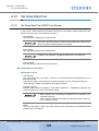
Hot Spare Disk Settings ................................................................................... 78
Create Hot Spare ....................................................................................................................... 78
Delete Hot Spare ....................................................................................................................... 80
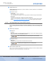
RAID Group Settings ........................................................................................ 81
Create RAID Group ................................................................................................................... 81
Delete RAID Group .................................................................................................................... 82
P2X0-0760-02ENZ0 ETERNUS DX400/DX8000 series ETERNUSmgr User Guide Settings/Maintenance
7
Copyright 2010 FUJITSU LIMITED
Contents
4.3
4.3.1
4.3.2
4.4
4.4.1
4.4.2
4.5
4.5.1
4.5.2
4.5.3
4.5.4
4.5.5
4.5.6
4.5.7
4.6
4.6.1
4.6.2
4.6.3
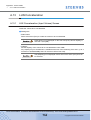
Thin Provisioning Pool Settings ....................................................................... 83
Create/Extend Thin Provisioning Pool ....................................................................................... 83
Delete Thin Provisioning Pool ................................................................................................... 84
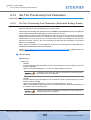
Logical Volume Settings ................................................................................... 85
Create Logical Volume .............................................................................................................. 85
Delete Logical Volume ............................................................................................................... 86
Open-CA Settings ............................................................................................ 87
Set CA Parameters .................................................................................................................... 87
Set Host World Wide Name(s) .................................................................................................. 88
Set iSCSI Host ........................................................................................................................... 89
Set Affinity Group ...................................................................................................................... 90
Allocate Host-Affinity Group ...................................................................................................... 91
Set LUN Mapping ...................................................................................................................... 92
Set CA Reset Group .................................................................................................................. 93
Mainframe-CA Settings .................................................................................... 94
Set CA Parameters .................................................................................................................... 94
Set LCU (ETERNUS DX8000 series only) ................................................................................ 95
Set IOA Mapping (ETERNUS DX8000 series only) .................................................................. 96
Chapter 5
5.1
5.1.1
5.1.2
5.1.3
5.2
5.2.1
5.2.2
5.2.3
5.2.4
5.2.5
5.2.6
5.2.7
5.2.8
5.2.9
5.2.10
5.2.11
5.2.12
5.2.13
5.2.14
5.2.15
5.2.16
5.2.17
Configuration Menu ...............................................................97
Resource Domain Management ...................................................................... 97
Set Resource Domain ............................................................................................................... 97
Assign Numerical Resource .................................................................................................... 103
Assign Resources .................................................................................................................... 108
RAID Management ......................................................................................... 143
Create RAID Group ................................................................................................................. 144
Rename RAID Group .............................................................................................................. 151
Change Controlling CM of RAID Group ................................................................................... 153
Logical Device Expansion ....................................................................................................... 156
Delete RAID Group .................................................................................................................. 165
Create Logical Volume ............................................................................................................ 167
Set Snap Data Pool ................................................................................................................. 182
Rename Logical Volume ......................................................................................................... 197
Convert Encryption Volume ..................................................................................................... 200
Format Logical Volume ............................................................................................................ 204
Initialize Snap Data Volume .................................................................................................... 210
RAID Migration ........................................................................................................................ 214
Progress of RAID Migration ..................................................................................................... 225
LUN Concatenation ................................................................................................................. 229
Delete Logical Volume ............................................................................................................. 236
Create Hot Spare ..................................................................................................................... 241
Delete Hot Spare ..................................................................................................................... 243
P2X0-0760-02ENZ0 ETERNUS DX400/DX8000 series ETERNUSmgr User Guide Settings/Maintenance
8
Copyright 2010 FUJITSU LIMITED
Contents
5.3
5.3.1
5.3.2
5.3.3
5.3.4
5.3.5
5.3.6
5.3.7
5.3.8
5.3.9
5.3.10
5.3.11
5.3.12
5.3.13
5.3.14
5.3.15
5.3.16
5.3.17
5.3.18
5.3.19
5.4
5.4.1
5.4.2
5.4.3
5.4.4
5.4.5
5.4.6
5.4.7
5.4.8
5.4.9
5.4.10
5.4.11
5.4.12
Thin Provisioning Management ...................................................................... 246
Create/Extend Thin Provisioning Pool ..................................................................................... 247
Set Thin Provisioning Pool Parameters ................................................................................... 266
Format Thin Provisioning Pool ................................................................................................ 270
Rename RAID Group .............................................................................................................. 274
Change Controlling CM of RAID Group ................................................................................... 274
Delete Thin Provisioning Pool ................................................................................................. 275
Create Logical Volume ............................................................................................................ 277
Rename Logical Volume ......................................................................................................... 277
Set Thin Provisioning Volume Parameters .............................................................................. 278
Format Logical Volume ............................................................................................................ 280
Thin Provisioning Volume Expansion ...................................................................................... 281
Balance Thin Provisioning Volume .......................................................................................... 284
Progress of Balance Thin Provisioning Volume ...................................................................... 290
RAID Migration ........................................................................................................................ 297
Progress of RAID Migration ..................................................................................................... 297
Delete Logical Volume ............................................................................................................. 297
Create Hot Spare ..................................................................................................................... 297
Delete Hot Spare ..................................................................................................................... 297
Register Thin Provisioning License ......................................................................................... 298
Host Interface Management ........................................................................... 300
Set CA Parameters .................................................................................................................. 300
Set Host World Wide Name(s) ................................................................................................ 327
Set iSCSI Host ......................................................................................................................... 338
Set Affinity Group .................................................................................................................... 355
Allocate Host-Affinity Group .................................................................................................... 375
Set LUN Mapping .................................................................................................................... 388
Set CA Reset Group ................................................................................................................ 398
Set Host Response .................................................................................................................. 401
Set LCU (ETERNUS DX8000 series only) .............................................................................. 417
Set IOA Mapping (ETERNUS DX8000 series only) ................................................................ 425
Change RA Mode .................................................................................................................... 437
Release Reservation ............................................................................................................... 444
Chapter 6
6.1
6.1.1
6.2
6.2.1
6.3
6.3.1
6.3.2
6.3.3
6.3.4
6.3.5
Settings Menu.......................................................................448
Setting Configuration ...................................................................................... 448
Set Configuration ..................................................................................................................... 448
Sub System Parameter .................................................................................. 452
Set Sub System Parameters ................................................................................................... 452
Advanced Copy Settings ................................................................................ 454
Set EC/OPC Priority ................................................................................................................ 455
Set REC Priority ...................................................................................................................... 456
Stop EC/OPC Session ............................................................................................................. 460
Stop REC Session ................................................................................................................... 464
Set Advanced Copy Table Size ............................................................................................... 467
P2X0-0760-02ENZ0 ETERNUS DX400/DX8000 series ETERNUSmgr User Guide Settings/Maintenance
9
Copyright 2010 FUJITSU LIMITED
Contents
6.3.6
6.3.7
6.3.8
6.3.9
6.3.10
6.3.11
6.4
6.4.1
6.4.2
6.4.3
6.5
6.5.1
6.5.2
6.5.3
6.5.4
6.6
6.6.1
6.6.2
6.6.3
6.6.4
6.7
6.7.1
6.8
6.8.1
6.8.2
6.8.3
6.8.4
Register Advanced Copy License ........................................................................................... 472
Set REC Buffer ........................................................................................................................ 474
Create REC Disk Buffer ........................................................................................................... 483
Format REC Disk Buffer .......................................................................................................... 490
Delete REC Disk Buffer ........................................................................................................... 493
Set Advanced Copy Event Notification .................................................................................... 495
SNMP ............................................................................................................. 498
Set SNMP Agent Environment ................................................................................................ 498
Download Extended MIB Definition File .................................................................................. 502
SNMP Trap Test ...................................................................................................................... 504
Eco-mode ....................................................................................................... 506
Set Common Eco-mode .......................................................................................................... 506
Set Eco-mode Schedule .......................................................................................................... 510
Set RAID Group-Eco-mode ..................................................................................................... 521
Set Thin Provisioning Pool-Eco-mode ..................................................................................... 532
Remote Advanced Copy Configuration .......................................................... 542
Export Advanced Copy Information ......................................................................................... 543
Create Advanced Copy Information ........................................................................................ 546
Set Advanced Copy Path ........................................................................................................ 580
Check Advanced Copy Path .................................................................................................... 585
Setting Encryption .......................................................................................... 587
Set Encryption Mode ............................................................................................................... 587
Others ............................................................................................................ 591
Set IP Address for USER Port ................................................................................................. 591
Set IP Address for REMCS Port .............................................................................................. 598
Set Date and Time ................................................................................................................... 605
Set Box ID ............................................................................................................................... 608
Chapter 7
7.1
7.1.1
7.1.2
7.1.3
7.1.4
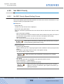
Download ....................................................................................................... 611
Export Configuration ................................................................................................................ 611
Export Log ............................................................................................................................... 612
Set Syslog ............................................................................................................................... 616
Export Panic Dump .................................................................................................................. 621
Chapter 8
8.1
8.1.1
8.1.2
8.2
8.2.1
8.2.2
8.2.3
Download Menu....................................................................611
Remote Support Menu .........................................................624
Display ........................................................................................................... 624
Display Support Settings ......................................................................................................... 624
Communication Log ................................................................................................................. 626
Set .................................................................................................................. 627
Set Remote Support ................................................................................................................ 627
Update Customer Information ................................................................................................. 632
Change Communication Environment Information .................................................................. 635
P2X0-0760-02ENZ0 ETERNUS DX400/DX8000 series ETERNUSmgr User Guide Settings/Maintenance
10
Copyright 2010 FUJITSU LIMITED
Contents
8.3
8.3.1
8.3.2
Operation ....................................................................................................... 639
Sending Log ............................................................................................................................ 639
Pause/Restart Remote Support ............................................................................................... 643
Chapter 9
9.1
9.1.1
9.1.2
9.1.3
User Accounts Menu............................................................645
Account .......................................................................................................... 645
Set User Account ..................................................................................................................... 645
Set Role ................................................................................................................................... 655
Set RADIUS Authentication ..................................................................................................... 663
Appendix A Screen Details.......................................................................669
A.1
A.1.1
A.2
A.2.1
A.3
A.3.1
A.4
A.4.1
A.4.2
A.5
A.5.1
A.6
A.6.1
A.6.2
A.6.3
A.6.4
A.6.5
A.6.6
A.7
A.7.1
A.8
A.8.1
A.9
A.9.1
A.9.2
A.9.3
A.9.4
A.9.5
A.9.6
A.9.7
A.10
Device Status .................................................................................................. 669
Device Status (Collect Device Information) Screen................................................................. 669
Resource Domain List ..................................................................................... 671
Resource Domain List (Initial) Screen ..................................................................................... 671
RAID Group List .............................................................................................. 673
RAID Group List (Initial) Screen .............................................................................................. 673
Thin Provisioning Pool List .............................................................................. 676
Thin Provisioning Pool List (Pool List) Screen......................................................................... 676
Thin Provisioning Pool List (Volume List in the Pool) Screen.................................................. 678
Volume List ..................................................................................................... 682
Volume List (Initial) Screen...................................................................................................... 682
Advanced Copy Status.................................................................................... 688
Advanced Copy Status (EC Session List) Screen...................................................................
Advanced Copy Status (OPC Session List) Screen ................................................................
Advanced Copy Status (EC Session Details/OPC Session Details) Screen...........................
Advanced Copy Status (REC Session List) Screen ................................................................
Advanced Copy Status (REC Session Details) Screen...........................................................
Advanced Copy Status (Advanced Copy Path Status) Screen ...............................................
688
690
693
695
697
699
Set Resource Domain ..................................................................................... 703
Set Resource Domain (Create Resource Domains) Screen ................................................... 703
Assign Numerical Resource............................................................................ 704
Assign Numerical Resource (Set Assignable Resources) Screen .......................................... 704
Assign Resources ........................................................................................... 705
Assign Resources (Set RAID Group) Screen..........................................................................
Assign Resources (Set TPP) Screen ......................................................................................
Assign Resources (Set Host WWN) Screen............................................................................
Assign Resources (Set iSCSI Host) Screen............................................................................
Assign Resources (Set Affinity Group) Screen........................................................................
Assign Resources (Set Host Response) Screen.....................................................................
Assign Resources (Set Eco-mode Schedule) Screen .............................................................
705
706
707
709
710
711
714
Create RAID Group......................................................................................... 716
A.10.1 Create RAID Group (Initial) Screen ......................................................................................... 716
P2X0-0760-02ENZ0 ETERNUS DX400/DX8000 series ETERNUSmgr User Guide Settings/Maintenance
11
Copyright 2010 FUJITSU LIMITED
Contents
A.11
Create Logical Volume................................................................................... 720
A.11.1 Create Logical Volume (Create Logical Volume) Screen ........................................................ 720
A.11.2 Create Logical Volume (Create Thin Provisioning Volume) Screen........................................ 727
A.12
Set Snap Data Pool......................................................................................... 729
A.12.1 Set Snap Data Pool (SDPV List) Screen................................................................................. 729
A.12.2 Set Snap Data Pool (Create SDPV) Screen............................................................................ 731
A.12.3 Set Snap Data Pool (Select SDPV) Screen ............................................................................ 732
A.13
LUN Concatenation......................................................................................... 734
A.13.1 LUN Concatenation (Input Volume) Screen ............................................................................ 734
A.14
Set Thin Provisioning Pool Parameters .......................................................... 735
A.14.1 Set Thin Provisioning Pool Parameters (Notification Setting) Screen ..................................... 735
A.15
Format Thin Provisioning Pool ........................................................................ 737
A.15.1 Format Thin Provisioning Pool (Select Format Type) Screen ................................................. 737
A.16
Set Thin Provisioning Volume Parameters ..................................................... 738
A.16.1 Set Thin Provisioning Volume Parameters (Notification Setting) Screen ................................ 738
A.17
Balance Thin Provisioning Volume ................................................................. 739
A.17.1 Balance Thin Provisioning Volume (Select Balancing TPV) Screen ....................................... 739
A.18
A.18.1
A.18.2
A.18.3
A.18.4
A.18.5
A.18.6
A.18.7
A.19
Set CA Parameters ......................................................................................... 741
Set CA Parameters (FC-CA Detailed Settings) Screen...........................................................
Set CA Parameters (FC-RA Detailed Settings) Screen...........................................................
Set CA Parameters (RFCF-RA Detailed Settings) Screen......................................................
Set CA Parameters (OCLINK Detailed Settings) Screen ........................................................
Set CA Parameters (FCLINK Detailed Settings) Screen.........................................................
Set CA Parameters (iSCSI-CA Detailed Settings) Screen ......................................................
Set CA Parameters (iSCSI-RA Detailed Settings) Screen ......................................................
741
744
745
747
747
748
752
Set Host World Wide Name(s) ........................................................................ 756
A.19.1 Set Host World Wide Name(s) (Initial) Screen ........................................................................ 756
A.20
Set iSCSI Host ................................................................................................ 759
A.20.1 Set iSCSI Host (Add) Screen .................................................................................................. 759
A.21
Set Affinity Group ............................................................................................ 761
A.21.1 Set Affinity Group (Initial) Screen ............................................................................................ 761
A.22
Set Host Response (Add Host Response) ...................................................... 764
A.22.1 Set Host Response (Initial) Screen ......................................................................................... 764
A.22.2 Set Host Response (Detailed Setting) Screen ........................................................................ 766
A.23
Release Reservation....................................................................................... 770
A.23.1 Release Reservation (Select Volume) Screen ........................................................................ 770
A.23.2 Release Reservation (Detail) Screen ...................................................................................... 772
A.24
Set Sub System Parameters ........................................................................... 773
A.24.1 Set Sub System Parameters (Initial) Screen ........................................................................... 773
A.25
Set REC Priority .............................................................................................. 775
A.25.1 Set REC Priority (Speed Setting) Screen ................................................................................ 775
A.26
Set Advanced Copy Table Size ...................................................................... 777
A.26.1 Set Advanced Copy Table Size (Initial) Screen....................................................................... 777
P2X0-0760-02ENZ0 ETERNUS DX400/DX8000 series ETERNUSmgr User Guide Settings/Maintenance
12
Copyright 2010 FUJITSU LIMITED
Contents
A.27
Set REC Buffer................................................................................................ 778
A.27.1 Set REC Buffer (Set) Screen................................................................................................... 778
A.27.2 Set REC Buffer (Add REC Disk Buffer) Screen....................................................................... 781
A.28
Set SNMP Agent Environment........................................................................ 782
A.28.1 Set SNMP Agent Environment (Initial) Screen ........................................................................ 782
A.29
Set Eco-mode Schedule ................................................................................. 786
A.29.1 Set Eco-mode Schedule (Set) Screen..................................................................................... 786
A.30
Set RAID Group-Eco-mode............................................................................. 790
A.30.1 Set RAID Group-Eco-mode (Set) Screen................................................................................ 790
A.31
Set Thin Provisioning Pool-Eco-mode ............................................................ 793
A.31.1 Set Thin Provisioning Pool-Eco-mode (Set) Screen................................................................ 793
A.32
Create Advanced Copy Information ................................................................ 795
A.32.1 Create Advanced Copy Information (Input New Device Information) Screen ......................... 795
A.33
Set IP Address for USER Port ........................................................................ 796
A.33.1 Set IP Address for USER Port (Initial) Screen......................................................................... 796
A.34
Set IP Address for REMCS Port ..................................................................... 798
A.34.1 Set IP Address for REMCS Port (Initial) Screen...................................................................... 798
A.35
Set Syslog ....................................................................................................... 800
A.35.1 Set Syslog (Initial) Screen ....................................................................................................... 800
A.36
Set Remote Support........................................................................................ 802
A.36.1 Set Remote Support (Initial) Screen........................................................................................ 802
A.37
Set User Account ............................................................................................ 808
A.37.1 Set User Account (Registration) Screen.................................................................................. 808
A.38
Set Role .......................................................................................................... 810
A.38.1 Set Role (Register Role/Change Role) Screen ....................................................................... 810
A.39
Set RADIUS Authentication ............................................................................ 814
A.39.1 Set RADIUS Authentication (Initial) Screen............................................................................. 814
Appendix B Notes on Access via https...................................................816
Appendix C Syslog Message List ............................................................822
C.1
C.1.1
C.1.2
C.2
C.2.1
C.2.2
C.2.3
C.2.4
Syslog Function............................................................................................... 822
Outline ..................................................................................................................................... 822
Message Format...................................................................................................................... 822
Syslog Message List ....................................................................................... 825
Common Terms.......................................................................................................................
Error Messages .......................................................................................................................
Warning Messages..................................................................................................................
Informational Messages ..........................................................................................................
825
826
830
835
P2X0-0760-02ENZ0 ETERNUS DX400/DX8000 series ETERNUSmgr User Guide Settings/Maintenance
13
Copyright 2010 FUJITSU LIMITED
Chapter 1
Operation Screens
The ETERNUSmgr backend program, which is embedded in the ETERNUS DX400/DX8000
series, is used to display the status of, setup and maintain the ETERNUS DX400/DX8000 series.
This chapter describes how this may be done.
1.1
Initial Screen
When using an ETERNUS DX400/DX8000 series, you must always keep a careful watch on its
status to monitor the device. Use either the ETERNUSmgr frontend or other operation management software. To start the initial screen, you should take different procedure, depending on the
monitoring method.
Two methods to manage ETERNUS DX400/DX8000 series are explained
in this guide. One is via the ETERNUSmgr frontend, and the other is to use
a Web browser to access the ETERNUSmgr backend program embedded
in the device.
Hereafter, "ETERNUSmgr" is generally used for all device management,
even those that use an ordinary Web browser.
P2X0-0760-02ENZ0 ETERNUS DX400/DX8000 series ETERNUSmgr User Guide Settings/Maintenance
14
Copyright 2010 FUJITSU LIMITED
Chapter 1 Operation Screens
>
1.1 Initial Screen
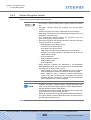
1.1.1
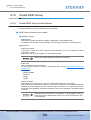
Use the ETERNUSmgr Frontend
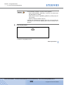
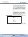
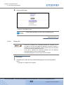
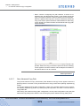
When using the ETERNUSmgr client, the initial screen is the ETERNUSmgr top menu.
Enter the URL of the top menu file ("menu.htm"), and the top menu will appear. For details of the
top menu file, please refer to the "ETERNUS Disk storage systems ETERNUSmgr User Guide Introduction-".
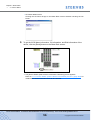
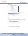
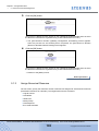
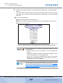
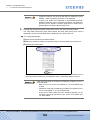
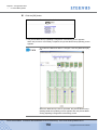
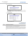
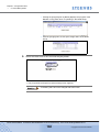
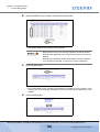
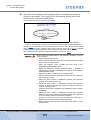
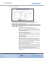
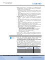
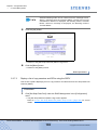
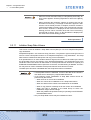
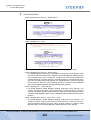
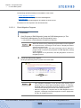
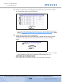
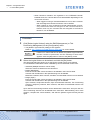
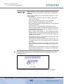
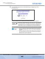
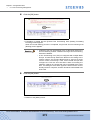
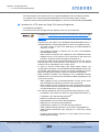
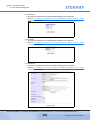
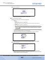
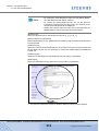
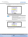
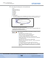
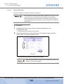
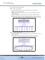
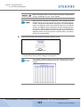
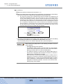
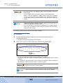
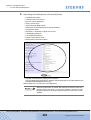
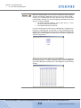
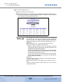
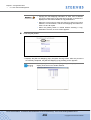
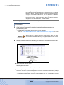
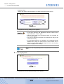
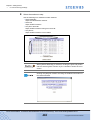
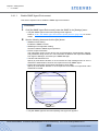
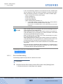
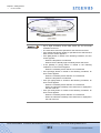
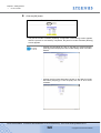
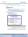
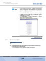
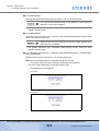
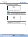
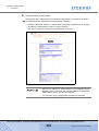
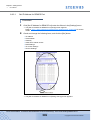
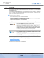
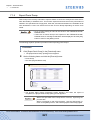
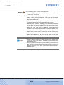
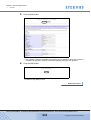
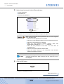
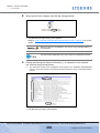
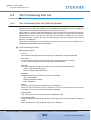
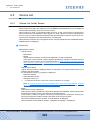
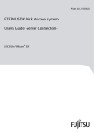
The following shows a typical ETERNUSmgr Top Menu screen.
● Select RAID Device menu
Click the name of a target device listed in the [Select RAID Device] menu to access the
device's logon screen. See "2.1 Logon" (page 37) for details on how to logon.
P2X0-0760-02ENZ0 ETERNUS DX400/DX8000 series ETERNUSmgr User Guide Settings/Maintenance
15
Copyright 2010 FUJITSU LIMITED
Chapter 1 Operation Screens
>
1.1 Initial Screen
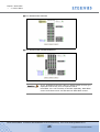
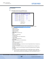
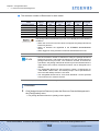
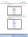
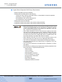
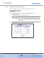
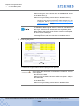
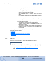
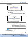
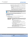
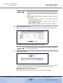
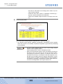
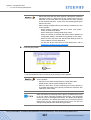
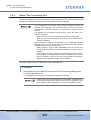
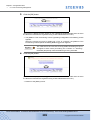
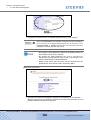
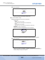
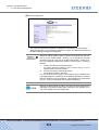
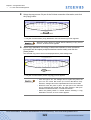
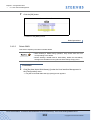
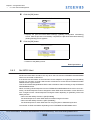
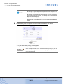
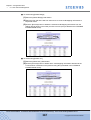
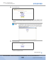
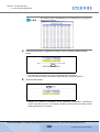
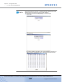
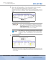
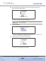
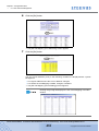
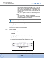
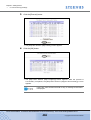
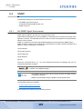
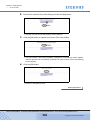
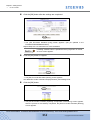
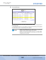
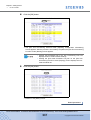
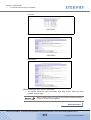
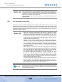
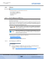
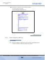
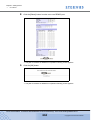
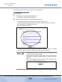
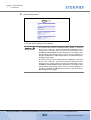
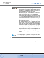
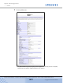
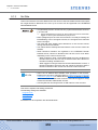
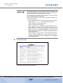
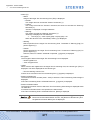
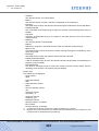
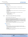
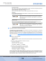
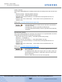
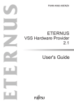
● Show hardware error detect log list menu
Click the name of a target device listed in the [Show hardware error detect log list] menu to
get a listing of the target device's error logs (alarm history files). This will require use of the
Web server's list display function. Refer to the User's Guide for the Web server being used for
more details.
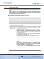
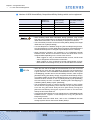
The status of the selected target device appears to the right of its alarm history file link. The
various statuses are described below.
Normal
(Black)
Indicates that device is operating without any error.
*Offline*
(Red)
Indicates that monitoring of the target device is not possible for one of the following
reasons: the ETERNUSmgr monitoring function is not active (e.g. immediately after
ETERNUSmgr installation). a problem has occurred with the target device (e.g.
power supply shutdown, no response), or a problem has occurred with the
communication link between the ETERNUSmgr server and the target device (e.g.
broken wiring, severe delays due to network overload).
The target device status will also be set to "Offline" if the Target Address
(TARGET_ADDR/TARGET_PORT) specified in the setup file is incorrect.
Check that the target device is operating normally, there is no problem with the
network connection, and the setup file details are correct.
This status will only be detected if a DETECT_OFFLINE=TRUE line is present in
the setup file. If this setting is not present, the machine will not change from
"Normal" or "ATTENTION" to "Offline".
*ATTENTION*
(Bold Red)
Indicates that one or more errors have been detected in the machine.
Log in to the machine and check the location of the fault.
*BUSY*
(Red)
Indicates that the device cannot respond due to device suspension, or because a
boot operation is currently in progress. Make sure that the device is operating
normally.
The statuses displayed on the top menu reflect the information current
when the top menu was last reloaded by the Web browser. The actual
current status of the target device may therefore not be displayed until
the top menu is reloaded. Always reload the top menu to check the
current target device status. Note that some Web browsers may display
a previously cached page even after the top menu is reloaded. See the
manual or online help for your Web browser for details.
Note that, depending on the browser being used, "Reload" may be
shown as "Refresh", etc.
P2X0-0760-02ENZ0 ETERNUS DX400/DX8000 series ETERNUSmgr User Guide Settings/Maintenance
16
Copyright 2010 FUJITSU LIMITED
Chapter 1 Operation Screens
>
1.1 Initial Screen
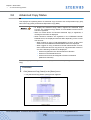
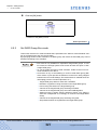
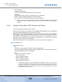
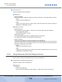
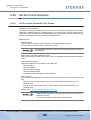
1.1.2
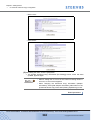
Use direct browser access to ETERNUSmgr Backend Program
When using operation management software other than ETERNUSmgr frontend, initial screen is
title screen of the ETERNUSmgr backend program embedded in the ETERNUS DX400/DX8000
series.
To check and maintain the ETERNUS DX400/DX8000 series, directly start the ETERNUSmgr
backend program embedded in the device from a PC on which Web browser runs. The following
are applicable Web browsers.
• Web browser
-
Microsoft® Internet Explorer 6.0 + Service Pack 2 (for Windows®)
Microsoft® Internet Explorer 7.0 (for Windows®)
Microsoft® Internet Explorer 8.0 (for Windows®)
Netscape 6.0 or later (for Windows®)
• Note the following:
- Set "Do not use proxy server" as the proxy setting.
- Set page acquisition to not use the cache.
- Enable the Java Script setting.
- When Auto Reading of pages is available, enable the setting.
• Furthermore, when using ETERNUSmgr with Microsoft® Internet
Explorer 7.0, note the following:
- Enable [Automatic prompting for file downloads] and [Allow websites
to open windows without address or status bars] under the Internet
Options Security tab.
• Furthermore, when using ETERNUSmgr with Microsoft® Internet
Explorer 8.0, note the following:
- Enable [Automatic prompting for file downloads] and [Allow websites
to open windows without address or status bars] under the Internet
Options Security tab.
- Disable the SmartScreen Filter in the [Tools] menu, or disable the
SmartScreen Filter by clicking the [Safety] button, or delete the
default gateway settings of the PC.
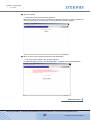
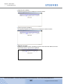
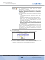
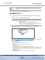
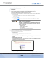
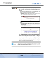
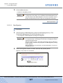
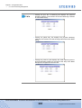
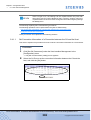
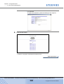
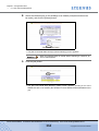
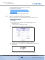
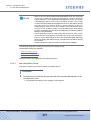
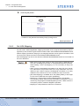
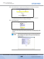
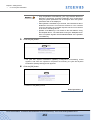
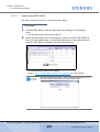
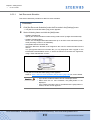
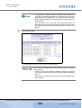
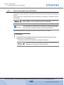
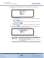
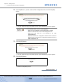
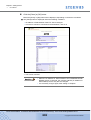
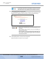
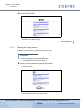
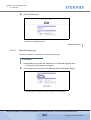
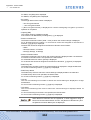
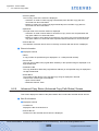
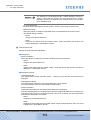
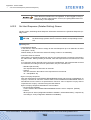
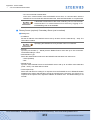
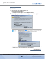
To access the ETERNUSmgr backend program, follow the procedures below.
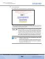
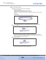
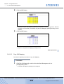
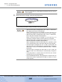
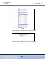
Procedure
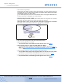
1
Establish a LAN connection between the PC and the ETERNUS DX400/DX8000
series USER port, then start the Web browser (To connect the PC directly to the
device USER port, a LAN straight cable is required).
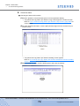
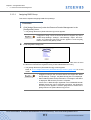
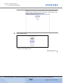
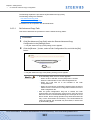
2
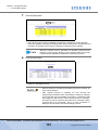
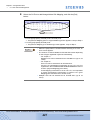
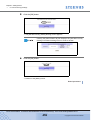
Input URL in the Web browser's address bar.
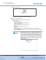
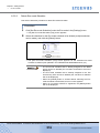
Specify "http://device_IP_address/" or "https://device_IP_address/".
→ The title screen of the ETERNUSmgr backend program appears.
P2X0-0760-02ENZ0 ETERNUS DX400/DX8000 series ETERNUSmgr User Guide Settings/Maintenance
17
Copyright 2010 FUJITSU LIMITED
Chapter 1 Operation Screens
>
1.1 Initial Screen
• There are two methods to specify the ETERNUS DX400/DX8000
series IP address: using "http" or "https". When placing emphasis
on security, use "https".
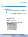
• Security certificate errors can occur when using https to access
an ETERNUS DX400/DX8000 series. Refer to "Appendix B Notes
on Access via https" (page 816) for a procedure to solve this https
access error.
• An IP address is not set for the ETERNUS DX400/DX8000 series
USER port at the factory, and should be set using the following
procedure:
1. Have the customer assign an IP address for the USER port.
2. When the ETERNUS DX400/DX8000 series is installed, use a LAN
straight through cable to connect the FST(*1) to the FST port whose
master LED is on.
*1: Maintenance engineer's Field Support Terminal.
3. Set the USER port IP address from the FST using the "Set IP Address for
USER Port" menu. This setting should be performed by the maintenance
engineer.
4. Use the USER port IP address (the ETERNUS DX400/DX8000 series's
IP address) and start the PC.
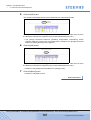
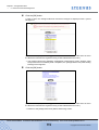
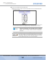
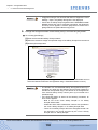
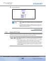
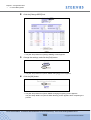
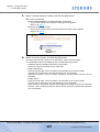
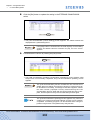
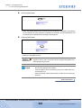
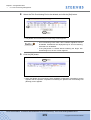
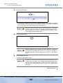
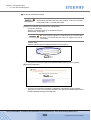
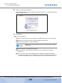
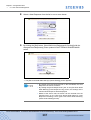
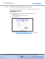
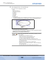
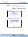
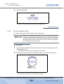
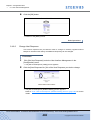
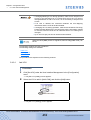
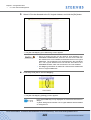
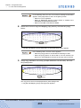
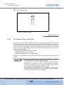
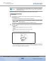
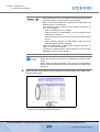
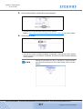
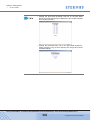
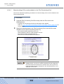
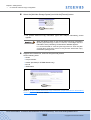
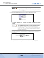
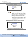
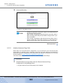
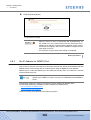
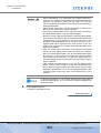
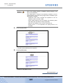
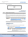
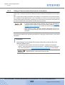
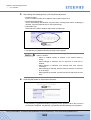
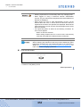
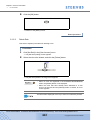
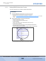
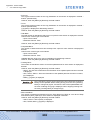
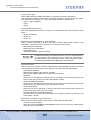
3
Click the "ETERNUS" logo on the title screen.
The "ETERNUS" indicates "ETERNUS DX410/DX440" or "ETERNUS DX8100/DX8400/
DX8700".
→ The ETERNUS DX400/DX8000 series logon screen appears. See "2.1 Logon" (page
37) for details on how to logon.
End of procedure
P2X0-0760-02ENZ0 ETERNUS DX400/DX8000 series ETERNUSmgr User Guide Settings/Maintenance
18
Copyright 2010 FUJITSU LIMITED
Chapter 1 Operation Screens
>
1.2 Operations Menu
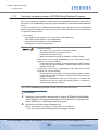
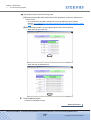
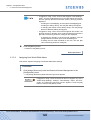
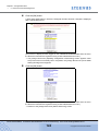
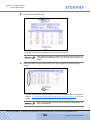
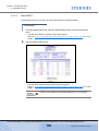
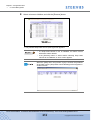
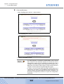
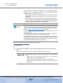
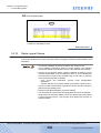
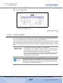
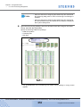
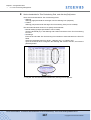
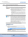
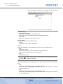
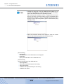
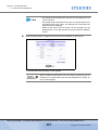
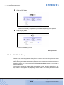
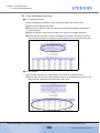
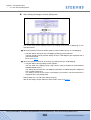
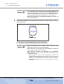
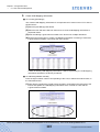
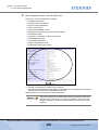
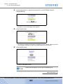
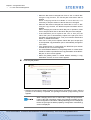
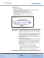
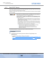
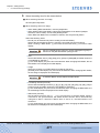
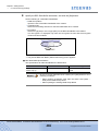
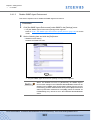
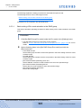
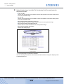
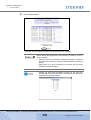
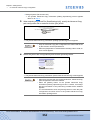
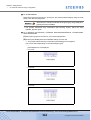
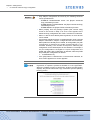
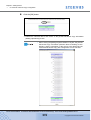
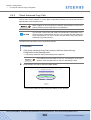
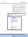
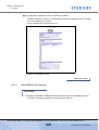
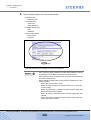
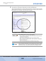
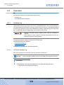
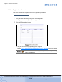
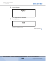
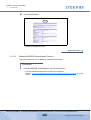
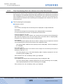
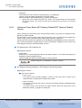
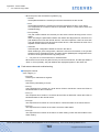
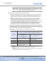
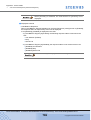
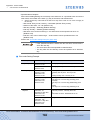
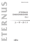
1.2
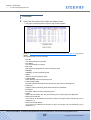
Operations Menu
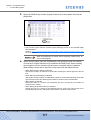
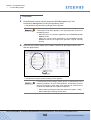
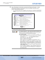
The operation menu consists of a Main menu and various Submenus. Selecting an item from the
Main menu will result in the relevant list of submenu items being displayed.
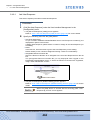
Main menu
Sub menu
(This screen is displayed when logged on the ETERNUS DX400/DX8000 series in which the
Resource Domains are registered using a Total Administrator account.)
Which menus are available will differ according to the account type. The system administrator
(root) can access various maintenance/setting menus (including the Status), and a regular user
can access the Status menus.
The system administrator is able to access the following menus:
•
•
•
•
•
•
•
Status menu
Getting Started menu
Configuration menu
Settings menu
Download menu
Remote Support menu
User Accounts menu
A regular user is only able to access the Status menu.
Operation menus may differ depending on the type of device. The different menus will be
described in each section.
The following describes the ETERNUSmgr main menu screens.
P2X0-0760-02ENZ0 ETERNUS DX400/DX8000 series ETERNUSmgr User Guide Settings/Maintenance
19
Copyright 2010 FUJITSU LIMITED
Chapter 1 Operation Screens
>
1.2 Operations Menu
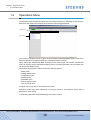
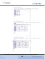
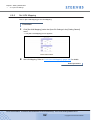
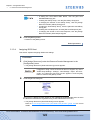
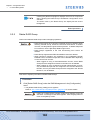
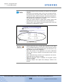
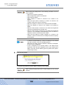
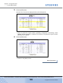
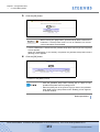
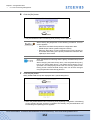
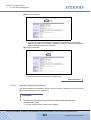
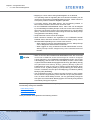
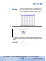
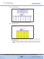
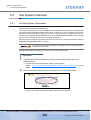
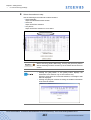
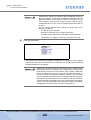
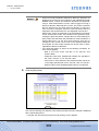
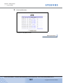
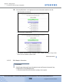
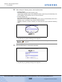
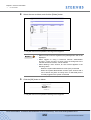
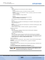
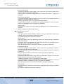
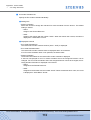
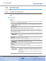
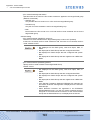
1.2.1
Status Menu
The Status menu is shown below. See "Chapter 3 Status Menu" (page 43) for an explanation of
its submenus and functions.
(This screen is displayed when logged on the ETERNUS DX400/DX8000 series in which the
Resource Domains are registered using a Total Administrator account.)
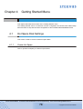
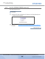
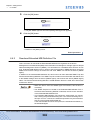
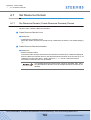
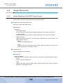
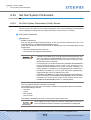
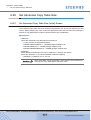
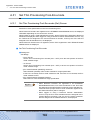
1.2.2
Getting Started Menu
The Getting Started menu is shown below. See "Chapter 4 Getting Started Menu" (page 78) for
an explanation of its submenus and functions.
(This screen is displayed when logged on the ETERNUS DX400/DX8000 series in which the
Resource Domains are registered using a Total Administrator account.)
P2X0-0760-02ENZ0 ETERNUS DX400/DX8000 series ETERNUSmgr User Guide Settings/Maintenance
20
Copyright 2010 FUJITSU LIMITED
Chapter 1 Operation Screens
>
1.2 Operations Menu
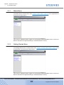
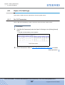
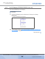
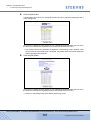
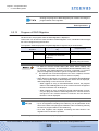
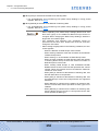
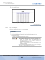
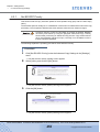
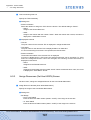
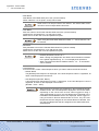
1.2.3
Configuration Menu
The Configuration menu is shown below. See "Chapter 5 Configuration Menu" (page 97) for an
explanation of its submenus and functions.
(This screen is displayed when logged on the ETERNUS DX400/DX8000 series in which the
Resource Domains are registered using a Total Administrator account.)
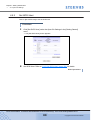
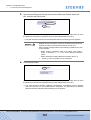
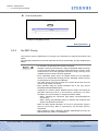
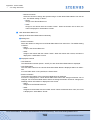
1.2.4
Settings Menu
The Settings menu is shown below. See "Chapter 6 Settings Menu" (page 448) for an explanation of its submenus and functions.
(This screen is displayed when logged on the ETERNUS DX400/DX8000 series in which the
Resource Domains are registered using a Total Administrator account.)
P2X0-0760-02ENZ0 ETERNUS DX400/DX8000 series ETERNUSmgr User Guide Settings/Maintenance
21
Copyright 2010 FUJITSU LIMITED
Chapter 1 Operation Screens
>
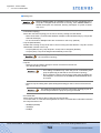
1.2 Operations Menu
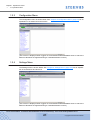
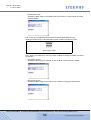
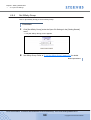
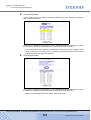
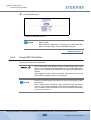
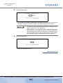
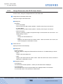
1.2.5
Download Menu
The Download menu is shown below. See "Chapter 7 Download Menu" (page 611) for an explanation of its submenus and functions.
(This screen is displayed when logged on the ETERNUS DX400/DX8000 series in which the
Resource Domains are registered using a Total Administrator account.)
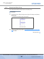
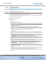
1.2.6
Remote Support Menu
The Remote Support menu is shown below. See "Chapter 8 Remote Support Menu" (page 624)
for an explanation of its submenus and functions.
(This screen is displayed when logged on the ETERNUS DX400/DX8000 series in which the
Resource Domains are registered using a Total Administrator account.)
P2X0-0760-02ENZ0 ETERNUS DX400/DX8000 series ETERNUSmgr User Guide Settings/Maintenance
22
Copyright 2010 FUJITSU LIMITED
Chapter 1 Operation Screens
>
1.2 Operations Menu
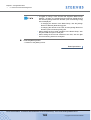
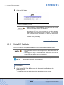
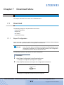
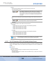
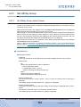
1.2.7
User Accounts Menu
The User Accounts Menu is shown below. See "Chapter 9 User Accounts Menu" (page 645) for
an explanation of its submenus and functions.
(This screen is displayed when logged on the ETERNUS DX400/DX8000 series in which the
Resource Domains are registered using a Total Administrator account.)
P2X0-0760-02ENZ0 ETERNUS DX400/DX8000 series ETERNUSmgr User Guide Settings/Maintenance
23
Copyright 2010 FUJITSU LIMITED
Chapter 1 Operation Screens
>
1.3 Screens when Resource Domains are registered
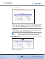
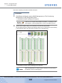
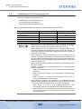
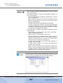
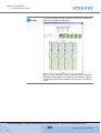
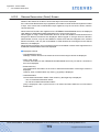
1.3
Screens when Resource Domains are registered
When Resource Domains are registered in the ETERNUS DX400/DX8000 series, the screen
that is displayed differs depending on the current user account.
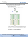
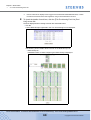
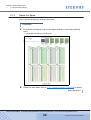
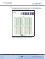
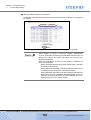
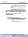
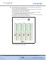
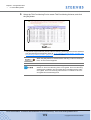
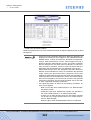
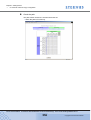
■ RAID Group List when logged on the ETERNUS DX400/DX8000 series using a Total
Administrator account
• All the RAID Groups that are assigned to the Resource Domains are displayed.
• The "Resource Domain" item is displayed.
P2X0-0760-02ENZ0 ETERNUS DX400/DX8000 series ETERNUSmgr User Guide Settings/Maintenance
24
Copyright 2010 FUJITSU LIMITED
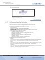
Chapter 1 Operation Screens
>
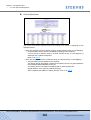
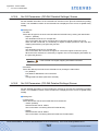
1.3 Screens when Resource Domains are registered
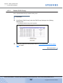
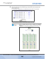
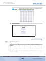
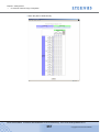
■ RAID Group List when logged on the ETERNUS DX400/DX8000 series using a
Resource Domain Administrator account
• [Resource Domain No. / Name] is displayed in the next of the status lamp.
• Only RAID Groups that are assigned to the Resource Domain (0x00 in the above screen) of
the current user account, and only the RAID Groups that are assigned to the Shared
Resource, are displayed.
• The "Resource Domain" item is not displayed.
P2X0-0760-02ENZ0 ETERNUS DX400/DX8000 series ETERNUSmgr User Guide Settings/Maintenance
25
Copyright 2010 FUJITSU LIMITED
Chapter 1 Operation Screens
>
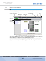
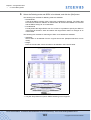
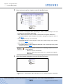
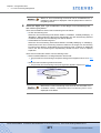
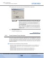
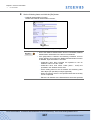
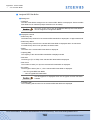
1.4 Screen Operations
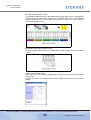
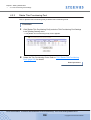
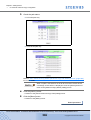
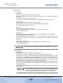
1.4
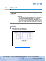
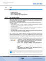
Screen Operations
This section describes the various screens used to setup and/or perform maintenance on the
device using ETERNUSmgr.
Logon user name
Controller firmware version
Model name
[Logoff] link
Help
Serial number
General status
lamp
Main menu
Current
function
Sub menu
From "2.2 Logoff" onward, the procedures use this part of the screen.
(This screen is displayed when logged on the ETERNUS DX400/DX8000 series in which the
Resource Domains are registered using a Total Administrator account.)
To view the details of a function during operation, click the [Help] link. A help screen appears.
Refer to the error messages displayed during operation in each setting window to deal with
errors.
P2X0-0760-02ENZ0 ETERNUS DX400/DX8000 series ETERNUSmgr User Guide Settings/Maintenance
26
Copyright 2010 FUJITSU LIMITED
Chapter 1 Operation Screens
>
1.4 Screen Operations
• When using ETERNUSmgr:
- Unless specified otherwise, never use the Back (←), Forward (→),
and Close Window (X), Refresh (⇔) browser buttons. Reloading
may cause program malfunction.
The window's buttons can be used to change the size of the window.
However, when Netscape is used on Solaris OS, you may need to
reload if you change the window size when logging on.
- It is recommended that the screen resolution be set to 800 × 600 to
better display the contents (part names, etc.) and to make it easier to
perform setting and maintenance.
- It is recommended to hide the standard Web browser buttons and
address bar to prevent incorrect operations while performing settings
and maintenance. Once the logon window is displayed, hide the
standard Web browser buttons and address bar.
- Be sure to logoff after all necessary operations are completed. If it is
not logged off, a massage will be displayed the next time you try to
logon. For details, see "2.1 Logon" (page 37).
• With a registered user account, the available operation menu varies
according to the role. For details, see "9.1.1 Set User Account" (page
645).When using the WWW browser:
- When using a network monitoring tool (such as "Norton Internet
Security" and "Norton Personal Firewall"), disable the monitoring tool
temporarily.
- When adding the URL to "Favorites", do not set to "Make available
offline".
- Do not click any button during browser communication.
- Do not click any button until the browser completes any display
process.
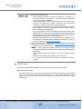
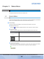
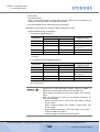
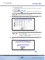
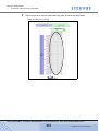
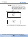
■ Screen Display
This section explains status displays, marks and links which appear on the screen.
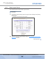
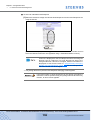
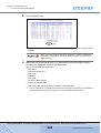
● General Status Display
The status of each device component is periodically checked and the summed result is shown
by the color and status of the device general status lamp. A green lamp indicates the device
status is normal, while the other colors indicate a problem with the status of some
components.
P2X0-0760-02ENZ0 ETERNUS DX400/DX8000 series ETERNUSmgr User Guide Settings/Maintenance
27
Copyright 2010 FUJITSU LIMITED
Chapter 1 Operation Screens
>
1.4 Screen Operations
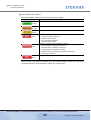
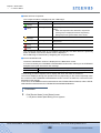
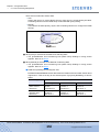
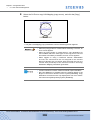
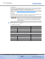
● General Status of the Device
The general status of the device is indicated by a "lamp image".
Lamp image
Description
Each component is in normal status.
(Green)
Component is under maintenance.
(Orange)
Preventive maintenance is required for some components.
(Yellow)
This lamp is displayed in the following conditions:
(Red)
• Component failure is detected.
Check the device status.
• FC-Loop Down is detected.
Check the device status.
This lamp is displayed in the following conditions:
(Red)
• Abnormal status is detected at power-on.
• Abnormal status is detected at power-off.
The device has not started up normally.
• Failed to restore the operating environment at power-on.
• The device is abnormal.
Other unknown
(Red)
Device monitor runs every five minutes.
General status of the device is determined by the combined status of each sub-component
(controller enclosure, drive enclosures, cables, etc.) of the device.
P2X0-0760-02ENZ0 ETERNUS DX400/DX8000 series ETERNUSmgr User Guide Settings/Maintenance
28
Copyright 2010 FUJITSU LIMITED
Chapter 1 Operation Screens
>
1.4 Screen Operations
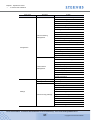
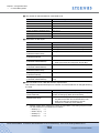
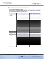
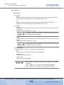
● Display of model and serial number
Model and serial number of the device are displayed by all functions.
Items
Model
Description
Display Contents
Model of the connected device are displayed.
•
•
•
•
•
•
(See left)
ETERNUS DX410
ETERNUS DX440
ETERNUS DX8100
ETERNUS DX8400
ETERNUS DX8700
MODEL unknown
(Caution)
When the model cannot be identified,
model name will be displayed as "MODEL
unknown". In such a case, some functions
cannot be used.
Serial number
Serial number of the connected device is
displayed.
Serial No.xxxxxxxxxx
(Caution)
When the serial number cannot be
identified, [-] (hyphen) will be displayed.
Product number
(Alphanumeric characters
up to 10) or [-]
Resource Domain
Resource Domain of the current user account
is displayed. If a Resource Domain name has
been registered, the Resource Domain name
is also displayed.
Resource Domain No.:0xXX
(Name:YYYYYYYYYYYYYYYY)
(Caution)
When Resource Domains are not registered, or when logged on using a Total
Administrator account, the "Resource
Domain" item is not displayed.
Resource Domain number
(0x00 – 0x07)
Resource Domain name (up
to 16 characters)
● Controller firmware versions
The controller firmware version of the ETERNUS DX400/DX8000 series can be checked in
the browser title bar.
Format
VxxLyy
Meaning
Integrated version number of the running firmware is displayed.
Vxx: Version
Lyy: Level
P2X0-0760-02ENZ0 ETERNUS DX400/DX8000 series ETERNUSmgr User Guide Settings/Maintenance
29
Copyright 2010 FUJITSU LIMITED
Chapter 1 Operation Screens
>
1.5 Menus and Submenus
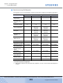
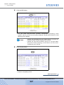
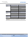
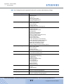
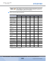
1.5
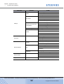
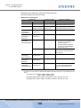
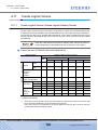
Menus and Submenus
The following shows the ETERNUSmgr menus, submenus, and functions.
The screen differs depending on the type of ETERNUS DX400/DX8000 series.
■ ETERNUS DX410/DX440
Main menu
Logon
Submenu
–
Screen
Logon
Device Status
Resource Domain List
Status
RAID Group List
–
Thin Provisioning Pool List
Volume List
Advanced Copy Status
Hot Spare Disk Settings
RAID Group Settings
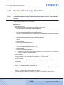
Getting Started
–
Thin Provisioning Pool Settings
Logical Volume Settings
Open-CA Settings
Resource Domain
Management
Set Resource Domain
Assign Numerical Resource
Assign Resources
Create RAID Group
Rename RAID Group
Change Controlling CM of RAID Group
Logical Device Expansion
Delete RAID Group
Create Logical Volume
Set Snap Data Pool
Configuration
Rename Logical Volume
RAID Management
Convert Encryption Volume
Format Logical Volume
Initialize Snap Data Volume
RAID Migration
Progress of RAID Migration
LUN Concatenation
Delete Logical Volume
Create Hot Spare
Delete Hot Spare
P2X0-0760-02ENZ0 ETERNUS DX400/DX8000 series ETERNUSmgr User Guide Settings/Maintenance
30
Copyright 2010 FUJITSU LIMITED
Chapter 1 Operation Screens
>
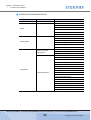
1.5 Menus and Submenus
Main menu
Submenu
Screen
Create/Extend Thin Provisioning Pool
Set Thin Provisioning Pool Parameters
Format Thin Provisioning Pool
Rename RAID Group
Change Controlling CM of RAID Group
Delete Thin Provisioning Pool
Create Logical Volume
Rename Logical Volume
Thin Provisioning
Management
Set Thin Provisioning Volume Parameters
Format Logical Volume
Thin Provisioning Volume Expansion
Balance Thin Provisioning Volume
Progress of Balance Thin Provisioning Volume
RAID Migration
Configuration
Progress of RAID Migration
Delete Logical Volume
Create Hot Spare
Delete Hot Spare
Register Thin Provisioning License
Set CA Parameters
Set Host World Wide Name(s)
Set iSCSI Host
Set Affinity Group
Host Interface
Management
Allocate Host-Affinity Group
Set LUN Mapping
Set CA Reset Group
Set Host Response
Change RA Mode
Release Reservation
Setting Configuration
Set Configuration
Sub System Parameter
Set Sub System Parameters
Set EC/OPC Priority
Set REC Priority
Stop EC/OPC Session
Stop REC Session
Settings
Set Advanced Copy Table Size
Advanced Copy Settings
Register Advanced Copy License
Set REC Buffer
Create REC Disk Buffer
Format REC Disk Buffer
Delete REC Disk Buffer
Set Advanced Copy Event Notification
P2X0-0760-02ENZ0 ETERNUS DX400/DX8000 series ETERNUSmgr User Guide Settings/Maintenance
31
Copyright 2010 FUJITSU LIMITED
Chapter 1 Operation Screens
>
1.5 Menus and Submenus
Main menu
Submenu
Screen
Set SNMP Agent Environment
SNMP
Download Extended MIB Definition File
SNMP Trap Test
Set Common Eco-mode
Eco-mode
Set Eco-mode Schedule
Set RAID Group-Eco-mode
Set Thin Provisioning Pool-Eco-mode
Settings
Export Advanced Copy Information
Remote Advanced Copy
Configuration
Create Advanced Copy Information
Set Advanced Copy Path
Check Advanced Copy Path
Setting Encryption
Set Encryption Mode
Set IP Address for USER Port
Set IP Address for REMCS Port
Others
Set Date and Time
Set Box ID
Export Configuration
Download
Export Log
–
Set Syslog
Export Panic Dump
Display Support Settings
Display
Communication Log
Set Remote Support
Remote Support
Update Customer Information
Set
Change Communication Environment
Information
Sending Log
Operation
Pause/Restart Remote Support
Set User Account
User Accounts
–
Set Role
Set RADIUS Authentication
Logoff
–
Logoff
P2X0-0760-02ENZ0 ETERNUS DX400/DX8000 series ETERNUSmgr User Guide Settings/Maintenance
32
Copyright 2010 FUJITSU LIMITED
Chapter 1 Operation Screens
>
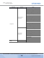
1.5 Menus and Submenus
■ ETERNUS DX8100/DX8400/DX8700
Main menu
Logon
Submenu
–
Screen
Logon
Device Status
Resource Domain List
Status
RAID Group List
–
Thin Provisioning Pool List
Volume List
Advanced Copy Status
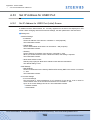
Hot Spare Disk Settings
RAID Group Settings
Getting Started
Thin Provisioning Pool Settings
–
Logical Volume Settings
Open-CA Settings
Mainframe-CA Settings
Resource Domain
Management
Set Resource Domain
Assign Numerical Resource
Assign Resources
Create RAID Group
Rename RAID Group
Change Controlling CM of RAID Group
Logical Device Expansion
Delete RAID Group
Create Logical Volume
Set Snap Data Pool
Configuration
Rename Logical Volume
RAID Management
Convert Encryption Volume
Format Logical Volume
Initialize Snap Data Volume
RAID Migration
Progress of RAID Migration
LUN Concatenation
Delete Logical Volume
Create Hot Spare
Delete Hot Spare
P2X0-0760-02ENZ0 ETERNUS DX400/DX8000 series ETERNUSmgr User Guide Settings/Maintenance
33
Copyright 2010 FUJITSU LIMITED
Chapter 1 Operation Screens
>
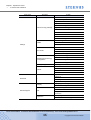
1.5 Menus and Submenus
Main menu
Submenu
Screen
Create/Extend Thin Provisioning Pool
Set Thin Provisioning Pool Parameters
Format Thin Provisioning Pool
Rename RAID Group
Change Controlling CM of RAID Group
Delete Thin Provisioning Pool
Create Logical Volume
Rename Logical Volume
Thin Provisioning
Management
Set Thin Provisioning Volume Parameters
Format Logical Volume
Thin Provisioning Volume Expansion
Balance Thin Provisioning Volume
Progress of Balance Thin Provisioning Volume
RAID Migration
Progress of RAID Migration
Configuration
Delete Logical Volume
Create Hot Spare
Delete Hot Spare
Register Thin Provisioning License
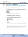
Set CA Parameters
Set Host World Wide Name(s)
Set iSCSI Host
Set Affinity Group
Allocate Host-Affinity Group
Host Interface
Management
Set LUN Mapping
Set CA Reset Group
Set Host Response
Set LCU
Set IOA Mapping
Change RA Mode
Release Reservation
Settings
Setting Configuration
Set Configuration
Sub System Parameter
Set Sub System Parameters
P2X0-0760-02ENZ0 ETERNUS DX400/DX8000 series ETERNUSmgr User Guide Settings/Maintenance
34
Copyright 2010 FUJITSU LIMITED
Chapter 1 Operation Screens
>
1.5 Menus and Submenus
Main menu
Submenu
Screen
Set EC/OPC Priority
Set REC Priority
Stop EC/OPC Session
Stop REC Session
Set Advanced Copy Table Size
Advanced Copy Settings
Register Advanced Copy License
Set REC Buffer
Create REC Disk Buffer
Format REC Disk Buffer
Delete REC Disk Buffer
Set Advanced Copy Event Notification
Set SNMP Agent Environment
SNMP
Download Extended MIB Definition File
Settings
SNMP Trap Test
Set Common Eco-mode
Eco-mode
Set Eco-mode Schedule
Set RAID Group-Eco-mode
Set Thin Provisioning Pool-Eco-mode
Export Advanced Copy Information
Remote Advanced Copy
Configuration
Create Advanced Copy Information
Set Advanced Copy Path
Check Advanced Copy Path
Setting Encryption
Set Encryption Mode
Set IP Address for USER Port
Set IP Address for REMCS Port
Others
Set Date and Time
Set Box ID
Export Configuration
Download
Export Log
–
Set Syslog
Export Panic Dump
Display Support Settings
Display
Communication Log
Set Remote Support
Remote Support
Update Customer Information
Set
Change Communication Environment
Information
Sending Log
Operation
Pause/Restart Remote Support
P2X0-0760-02ENZ0 ETERNUS DX400/DX8000 series ETERNUSmgr User Guide Settings/Maintenance
35
Copyright 2010 FUJITSU LIMITED
Chapter 1 Operation Screens
>
1.5 Menus and Submenus
Main menu
Submenu
Screen
Set User Account
User Accounts
–
Set Role
Set RADIUS Authentication
Logoff
–
Logoff
P2X0-0760-02ENZ0 ETERNUS DX400/DX8000 series ETERNUSmgr User Guide Settings/Maintenance
36
Copyright 2010 FUJITSU LIMITED
Chapter 2
Logon/Logoff
This chapter describes how to logon to and logoff from ETERNUSmgr.
2.1
Logon
Logon to ETERNUSmgr to start operation.
The menu displayed pertains to the logged on user accounts' role.
• A role is assigned to a user account. Available functions vary depending
on the role. A user can use allowed functions for each role. Multiple
roles may be assigned to a user account. Select a role to be used when
logging on with a user account with multiple roles.
In this manual, "system administrator" indicates the user who has
update authority (other than [Read Only]).
• When logged on using a Resource Domain Administrator account, the
following functions are not displayed regardless of the assigned role.
- Set Resource Domain
- Assign Numerical Resource
- Assign Resources
- Change RA Mode
- Set Configuration
- Set REC Priority
- Set REC Buffer
- Create REC Disk Buffer
- Format REC Disk Buffer
- Delete REC Disk Buffer
- Set Advanced Copy Event Notification
- Export Advanced Copy Information
- Create Advanced Copy Information
- Set Advanced Copy Path
- Check Advanced Copy Path
- Display Support Settings
- Communication Log
- Set Remote Support
- Update Customer Information
- Change Communication Environment Information
- Sending Log
- Pause/Restart Remote Support
P2X0-0760-02ENZ0 ETERNUS DX400/DX8000 series ETERNUSmgr User Guide Settings/Maintenance
37
Copyright 2010 FUJITSU LIMITED
Chapter 2 Logon/Logoff
>
2.1 Logon
• An error will occur, if logged on in the following situations. Check the
error message first, and either forcibly log off all users, or wait and retry
logon later.
- When the last operation was terminated without logging off.
- When a system administrator or maintenance engineer has already
logged on.
- When another application is already logging on.
• The starting screen of the ETERNUSmgr differs depending on the
language setting of the browser. To switch to Japanese mode, click the
[Japanese] button. To switch to English mode, click the [English] button.
Items
Description
Jumps to the English Logon screen of ETERNUSmgr.
All the screens after logon will be displayed in English.
Jumps to the Japanese Logon screen of ETERNUSmgr.
All the screens after logon will be displayed in Japanese.
• Refer to the "9.1.2 Set Role" (page 655) menu for allowed functions for
each role. The [Set Role] function can be started up when logging on
with a user account which has default role [account] or category
[Account Settings].
The following explains the logon procedures.
Procedure
1
Enter [User Name] and [Password] on the logon screen and click the [Logon]
button.
[User Name] and [Password] differ, depending on the account type.
The default system administrator user name and password are as follows:
• User Name: root
• Password: root (Default)
For details on general user accounts, refer to "9.1.1 Set User Account" (page 645).
If an input error screen appears, enter user name and password
again to perform the logon operation.
When RADIUS Authentication is used, an input error screen appears
if authentication fails.
P2X0-0760-02ENZ0 ETERNUS DX400/DX8000 series ETERNUSmgr User Guide Settings/Maintenance
38
Copyright 2010 FUJITSU LIMITED
Chapter 2 Logon/Logoff
>
2.1 Logon
→ When logged on with a user account that has multiple roles, select the role.
The [Logon (Select Role)] screen appears.
2
Select the role, and click the [Execute] button.
When logged on with a user account that has multiple roles,
selecting a role is required. When the user account has only one
role, the [Logon (Select Role)] screen does not appear.
P2X0-0760-02ENZ0 ETERNUS DX400/DX8000 series ETERNUSmgr User Guide Settings/Maintenance
39
Copyright 2010 FUJITSU LIMITED
Chapter 2 Logon/Logoff
>
2.1 Logon
■ When there are no other users logged on
→ The [Menu] screen is displayed.
• When the ETERNUS DX400/DX8000 series is under
maintenance work, a message to that effect appears. Clicking the
[Cancel] button displays a message such as "Under
Maintenance". Log off from the ETERNUSmgr and wait until the
maintenance operation is complete.
• When the ETERNUS DX400/DX8000 series is being set up, a
message to that effect appears. Clicking the [OK] button displays
a progress report. Wait until the setup procedure is complete. If
the [Cancel] button is clicked, ETERNUSmgr does not produce a
progress report. Click the function menu link. If the same
message appears again, click the [OK] button. No other menu
can be executed until the setup procedure completes.
• When the ETERNUS DX400/DX8000 series is under
maintenance work or being set up, device status may be checked
by clicking the [Device Status], [RAID Group List], or [Volume List]
links.
■ When attempting to log on, another system administrator, maintenance engineer, or
application is already logged on.
→ The [Logon (Forcible Logon)] screen appears.
To forcibly log off other users in order to logon, click the [OK] button to continue the logon
operation.
The other users will not be notified that another user forcibly logged
on.
P2X0-0760-02ENZ0 ETERNUS DX400/DX8000 series ETERNUSmgr User Guide Settings/Maintenance
40
Copyright 2010 FUJITSU LIMITED
Chapter 2 Logon/Logoff
>
2.1 Logon
■ When recovering
→ The [Logon (Lock Control)] screen appears.
When the number of the lock command retry attempts exceeds a certain number, the
recovery process fails, and the [Logon (Lock Control Error)] screen appears.
■ When an error occurs while acquiring the model information
→ The [Logon (Error Notice Logon)] screen appears.
To display the [Menu] screen, click the [OK] button. To log off, click the [Logoff] button.
End of procedure
P2X0-0760-02ENZ0 ETERNUS DX400/DX8000 series ETERNUSmgr User Guide Settings/Maintenance
41
Copyright 2010 FUJITSU LIMITED
Chapter 2 Logon/Logoff
>
2.2 Logoff
2.2
Logoff
To finish operations, log off the ETERNUSmgr.
If you close the window without logging off, the forcible logon message will
be displayed at the next logon. You must log off when finishing operation
with ETERNUSmgr.
Operating procedures for logoff are explained as follows.
Procedure
1
Click the [Logoff] link.
→ The [Logoff] screen appears.
2
Click the [OK] button.
End of procedure
P2X0-0760-02ENZ0 ETERNUS DX400/DX8000 series ETERNUSmgr User Guide Settings/Maintenance
42
Copyright 2010 FUJITSU LIMITED
Chapter 3
Status Menu
This chapter describes the functions of the Status menu.
3.1
Device Status
This screen displays the status of each component that configures ETERNUS DX400/DX8000
series, such as controller enclosure (CE), drive enclosure (DE), cables, etc.
■ Screen Display
This section explains status displays, marks and links which appear on the screen.
● Detailed Information Icon
Clicking the
icon displays detailed information of the component in another window.
● Component Display
Display of components differs between undefined/uninstalled cases and other cases.
Component Image
State
Undefined/Uninstalled
Others
Device monitor runs every five minutes.
● Component Status Display
A green status LED indicates normal status, and the other colors indicate some failures.
When moving the cursor to the LED of each component, the status is displayed.
P2X0-0760-02ENZ0 ETERNUS DX400/DX8000 series ETERNUSmgr User Guide Settings/Maintenance
43
Copyright 2010 FUJITSU LIMITED
Chapter 3 Status Menu
>
3.1 Device Status
● Status of Each Component
The component status is displayed by the "LED image".
LED image
(Green)
(Blue)
(Orange)
(Yellow)
(Red)
(Red)
State
Description
Normal
Each component is in normal status.
Warning
Some components are installed but unused.
(Note)
When the components are disk drives, the [Normal
(Green)] lamp is displayed instead of the [Warning
(Blue)] lamp for the general status of the device.
Maintenance
Component is under maintenance.
Warning
Preventive maintenance is required for some
components.
Alarm
Component failure is detected.
Error
Other unknown
The component status LEDs is not updated automatically, but rather when the [Refresh]
button is clicked or the Device Status screen is displayed.
Each LED image is determined by integrating the component status.
● Device Identification No.
The device identification number is displayed in the Base Rack screen.
It is used to identify the ETERNUS DX400/DX8000 series when referring to the ETERNUS
Multipath Driver path information and message.
Format
xxxxxx
Meaning
Device identification number is displayed (six ASCII code characters).
The following procedure explains how to display and check the status of the device.
The screens displayed during this operation will vary depending on the model. Especially when
the contents of the ETERNUS DX400/DX8000 series screens are different, both screens are
described in this manual.
In this case, the ETERNUS DX440 is described as the ETERNUS DX410/DX440, and the ETERNUS DX8400 is described as the ETERNUS DX8100/DX8400/DX8700.
Procedure
1
Click [Device Status] in the [Status] menu.
→ The [Device Status (Base Rack)] screen appears.
P2X0-0760-02ENZ0 ETERNUS DX400/DX8000 series ETERNUSmgr User Guide Settings/Maintenance
44
Copyright 2010 FUJITSU LIMITED
Chapter 3 Status Menu
>
3.1 Device Status
■ for ETERNUS DX410/DX440
■ for ETERNUS DX8100/DX8400/DX8700
As for ETERNUS DX8100, [Device Status (Rack Screen)] is
displayed because they have no Expansion Rack.
Hereinafter, if it is not necessary to describe separately, "Base Rack
screen" and "Rack screen" are described as "Base Rack screen".
P2X0-0760-02ENZ0 ETERNUS DX400/DX8000 series ETERNUSmgr User Guide Settings/Maintenance
45
Copyright 2010 FUJITSU LIMITED
Chapter 3 Status Menu
>
3.1 Device Status
2
Click the image of each component in the Base Rack screen, and check the
component status.
• CE: Controller Enclosure screen
Clicking the CE image on the Base Rack screen enables checking the CE.
- for ETERNUS DX410/DX440
- for ETERNUS DX8100/DX8400/DX8700
P2X0-0760-02ENZ0 ETERNUS DX400/DX8000 series ETERNUSmgr User Guide Settings/Maintenance
46
Copyright 2010 FUJITSU LIMITED
Chapter 3 Status Menu
>
3.1 Device Status
Also, clicking a component in the CE enables checking the details of clicked
component
- CPSU details screen
Clicking the CPSU image on the CE screen enables checking the CPSU.
- CM details screen
Clicking the CM image on the CE screen enables checking the CM details.
- Memory details screen
Clicking the Memory image on the CE screen enables checking the memory details.
P2X0-0760-02ENZ0 ETERNUS DX400/DX8000 series ETERNUSmgr User Guide Settings/Maintenance
47
Copyright 2010 FUJITSU LIMITED
Chapter 3 Status Menu
>
3.1 Device Status
- CA details screen (FC)
Clicking the FC image on the CE screen enables checking the FC details.
- CA details screen (iSCSI-CA)
Clicking the iSCSI-CA image on the CE screen enables checking the iSCSI-CA
details.
- CA details screen (iSCSI-RA)
Clicking the iSCSI-RA image on the CE screen enables checking the iSCSI-RA
details.
P2X0-0760-02ENZ0 ETERNUS DX400/DX8000 series ETERNUSmgr User Guide Settings/Maintenance
48
Copyright 2010 FUJITSU LIMITED
Chapter 3 Status Menu
>
3.1 Device Status
- CA details screen (FCLINK)
Clicking the FCLINK image on the CE screen enables checking the FCLINK details.
- CA details screen (OCLINK)
Clicking the OCLINK image on the CE screen enables checking the OCLINK
details.
- SVC details screen (For ETERNUS DX8400 and DX8700 only)
Clicking the SVC image on the CE screen enables checking the SVC details.
P2X0-0760-02ENZ0 ETERNUS DX400/DX8000 series ETERNUSmgr User Guide Settings/Maintenance
49
Copyright 2010 FUJITSU LIMITED
Chapter 3 Status Menu
>
3.1 Device Status
- FRT details screen (For ETERNUS DX8400 and DX8700 only)
Clicking the FRT image on the CE screen enables checking the FRT details.
- BRT details screen (For ETERNUS DX8400 and DX8700 only)
Clicking the BRT image on the CE screen enables checking the BRT details.
• DE: Drive Enclosure screen
Clicking a DE image on the Base Rack screen enables checking the DE details.
- for ETERNUS DX410/DX440
P2X0-0760-02ENZ0 ETERNUS DX400/DX8000 series ETERNUSmgr User Guide Settings/Maintenance
50
Copyright 2010 FUJITSU LIMITED
Chapter 3 Status Menu
>
3.1 Device Status
- for ETERNUS DX8100/DX8400/DX8700
Also, clicking a component in the DE enables checking the details of clicked
component.
- Disk details screen
Clicking a Disk image on the DE screen enables checking the disk details.
- PBC details screen
Clicking the PBC image on the DE screen enables checking the PBC details.
P2X0-0760-02ENZ0 ETERNUS DX400/DX8000 series ETERNUSmgr User Guide Settings/Maintenance
51
Copyright 2010 FUJITSU LIMITED
Chapter 3 Status Menu
>
3.1 Device Status
- DPSU details screen
Clicking the DPSU image on the DE screen enables checking the DPSU details.
• Base Rack Power Source screen (For ETERNUS DX8400 and DX8700 only)
Clicking the Power Source image on the Base Rack screen enables checking the
power source.
Also, clicking a component in the Base Rack Power Source screen enables checking
the details of clicked component.
- BTU details screen
Clicking the BTU images on the Base Rack Power Source screen enables checking
the BTU details.
P2X0-0760-02ENZ0 ETERNUS DX400/DX8000 series ETERNUSmgr User Guide Settings/Maintenance
52
Copyright 2010 FUJITSU LIMITED
Chapter 3 Status Menu
>
3.1 Device Status
- BCU details screen
Clicking the BCU image on the Base Rack Power Source screen enables checking
the BCU details.
• PSE screen (For ETERNUS DX410/DX440, and ETERNUS DX8100 only)
Clicking the PSE image on the Base Rack screen enables checking the PSE.
Also, clicking a component in the PSE screen enables checking the details of clicked
component.
- BTU details screen
Clicking the BTU image on the PSE screen enables checking the BTU details.
- BCU details screen
Clicking the BCU image on the PSE screen enables checking the BCU details.
P2X0-0760-02ENZ0 ETERNUS DX400/DX8000 series ETERNUSmgr User Guide Settings/Maintenance
53
Copyright 2010 FUJITSU LIMITED
Chapter 3 Status Menu
>
3.1 Device Status
• FC-AL List screen
Clicking the FC Cable image on the Base Rack screen enables checking the FC
cables.
Clicking the [FC-AL#xx] link enables checking the FC-AL Attachment diagram.
• DEI List screen (For ETERNUS DX8400 and DX8700 only)
Clicking the DEI Cable image on the Base Rack screen enables checking the DEI
cables.
P2X0-0760-02ENZ0 ETERNUS DX400/DX8000 series ETERNUSmgr User Guide Settings/Maintenance
54
Copyright 2010 FUJITSU LIMITED
Chapter 3 Status Menu
>
3.1 Device Status
• DEI Attachment Diagram screen
For ETERNUS DX8100 click the DEI Cable image on the Rack screen, for ETERNUS
DX410 and DX440, click the DEI Cable image on the Base Rack screen, for ETERNUS
DX8400 and DX8700, click the DEI# on the DEI List screen, to check the DEI
Attachment Diagram screen.
• BBU Cable Attachment Diagram screen
Clicking the BBU Cable image on the Base Rack screen enables checking the BBU
Cables.
• Cache Control details screen
When the device is in the Write Through Mode, the [WT] link is displayed on the Base
Rack screen.
Clicking the WT link on the Base Rack screen enables checking the Cache Control
details.
P2X0-0760-02ENZ0 ETERNUS DX400/DX8000 series ETERNUSmgr User Guide Settings/Maintenance
55
Copyright 2010 FUJITSU LIMITED
Chapter 3 Status Menu
>
3.1 Device Status
• OP Panel details screen
Clicking the OP Panel image on the Base Rack screen enables checking the OP
Panel.
3
To get the iSCSI Name information, CA information, and Disk information of the
device, click the [Detail] button on the Base Rack screen.
→ The [Device Status (Select Device Information Collection)] screen appears.
Refer to "A.1.1 Device Status (Collect Device Information) Screen" (page 669) for
details about device information that can be collected.
P2X0-0760-02ENZ0 ETERNUS DX400/DX8000 series ETERNUSmgr User Guide Settings/Maintenance
56
Copyright 2010 FUJITSU LIMITED
Chapter 3 Status Menu
>
3.1 Device Status
4
To acquire the information all at once, click the [Batch acquisition] link. To select
and acquire information, click the selected information link of [Individual
acquisition].
→ After clicking each link, when acquiring device information the [Device Status
(Acquiring Device Information)] screen appears. After acquiring the device information,
the [Device Status (Save Device Information)] screen appears.
5
Click the [Download] button and save the acquired information.
The device information must be saved within one minute from the
time the [Download] button is clicked. If the download dialog box is
left open for over a minute, the download operation may terminate
with an unsuccessfully downloaded file.
If the downloaded file cannot be opened, the download may have
failed, so try the download again.
6
When checking the Expansion Rack status, click the "Expansion Rack#x" (x is
an expansion rack number), and perform the same procedure as for the Base
Rack.
End of procedure
P2X0-0760-02ENZ0 ETERNUS DX400/DX8000 series ETERNUSmgr User Guide Settings/Maintenance
57
Copyright 2010 FUJITSU LIMITED
Chapter 3 Status Menu
>
3.2 Resource Domain List
3.2
Resource Domain List
The list of Resource Domains registered in the ETERNUS DX400/DX8000 series is displayed.
• When Resource Domains are not registered in the ETERNUS DX400/
DX8000 series, the [Resource Domain List] menu is not displayed.
• When Resource Domains are registered in the ETERNUS DX400/
DX8000 series, the displayed Resource Domain information differs
depending on the current user account.
- When logged on using a Total Administrator account, all the
Resource Domain information registered in the ETERNUS DX400/
DX8000 series is displayed.
- When logged on using a Resource Domain Administrator account,
only the information for the relevant Resource Domain is displayed.
Resource Domains can be created using the [Set Resource Domain]
function.
The following explains procedures to display the Resource Domain List.
Procedure
1
Click [Resource Domain List] in the [Status] menu.
→ The [Resource Domain List (Initial)] screen appears.
(This screen is displayed when logged on the ETERNUS DX400/DX8000 series in which
the Resource Domains are registered using a Total Administrator account.)
Refer to "A.2.1 Resource Domain List (Initial) Screen" (page 671) for screen details.
P2X0-0760-02ENZ0 ETERNUS DX400/DX8000 series ETERNUSmgr User Guide Settings/Maintenance
58
Copyright 2010 FUJITSU LIMITED
Chapter 3 Status Menu
>
3.2 Resource Domain List
The following items can be checked:
• Resource Domain No.
The Resource Domain number
• Resource Domain Name
The name of the Resource Domain
• Status
The status of the Resource Domain
• TPPs
The number of Thin Provisioning Pools assigned to the Resource Domain
• RAID Groups
The number of RAID groups assigned to the Resource Domain
• Assigned Resources / Assignable Resources
The number of the following management target resources that have been assigned
and the maximum number of the management target resources which can be assigned
to the Resource Domains
- Logical Volume
- Host WWN
- iSCSI Host
- Affinity Group
- Host Response
- Eco-mode Schedule
2
Click the [Refresh] button to check the latest status.
3
Click the [Menu] button.
→ Returns to the [Menu] screen.
End of procedure
P2X0-0760-02ENZ0 ETERNUS DX400/DX8000 series ETERNUSmgr User Guide Settings/Maintenance
59
Copyright 2010 FUJITSU LIMITED
Chapter 3 Status Menu
>
3.3 RAID Group List
3.3
RAID Group List
This screen displays the list of RAID Groups and the detailed information of each RAID Group
created in the ETERNUS DX400/DX8000 series.
This function facilitates display of the status of each RAID Group and the Logical Volumes of
each RAID Group, aiding system administrators in their work.
• When no RAID Group is created in the ETERNUS DX400/DX8000
series, a message to that effect is displayed. Click the [OK] button to
return to the [Menu] screen.
• When Resource Domains are registered in the ETERNUS DX400/
DX8000 series, the displayed RAID Groups differ depending on the
current user account.
- When logged on using a Total Administrator account, all the RAID
Groups that are assigned to Resource Domains are displayed.
- When logged on using a Resource Domain Administrator account,
only the RAID Groups that are assigned to the relevant Resource
Domain, and only the RAID Groups that are assigned to the Shared
Resource, are displayed.
• It is possible to check the format progress status, encrypt progress
status, and detailed information for Snap Data volume and Snap Data
Pool volume from the [RAID Group List (Volume List in the RAID
Group)] screen for the RAID Group, as in the case of the [Volume List]
function.
• Check from the [Volume List] function to display all the Logical Volumes
created in the ETERNUS DX400/DX8000 series.
• Check from the [Thin Provisioning Pool List] function to display the list of
Thin Provisioning volumes in the RAID Group that is registered in the
Thin Provisioning Pool.
The following explains procedures to display/set the RAID Group List.
P2X0-0760-02ENZ0 ETERNUS DX400/DX8000 series ETERNUSmgr User Guide Settings/Maintenance
60
Copyright 2010 FUJITSU LIMITED
Chapter 3 Status Menu
>
3.3 RAID Group List
Procedure
1
Click [RAID Group List] in the [Status] menu.
→ The [RAID Group List (Initial)] screen appears.
Refer to "A.3.1 RAID Group List (Initial) Screen" (page 673) for screen details.
The following items can be checked:
• RAID Group No.
RAID Group number
• RAID Group Name
RAID Group name
• RAID Level
RAID level of the RAID Group
• Status
Status of the RAID Group
• Controlling CM
Controlling CM-CPU of the RAID Group
• Capacity (MB)
Capacity of the RAID Group
• DVCF Mode
DVCF mode (ON/OFF) of the RAID Group
• Usage
Volume type of the RAID Group
• Resource Domain No.
The number of the Resource Domain to which the target RAID Group is assigned (*1)
• Resource Domain Name
The name of the Resource Domain to which the target RAID Group is assigned (*1)
• TPP No.
The number of the Thin Provisioning Pool where the target RAID Group is registered
• TPP Name
The name of the Thin Provisioning Pool where the target RAID Group is registered
*1:
Resource Domain is displayed when logged on the ETERNUS DX400/DX8000 series, in
which the Resource Domains have been registered, using a Total Administrator account.
P2X0-0760-02ENZ0 ETERNUS DX400/DX8000 series ETERNUSmgr User Guide Settings/Maintenance
61
Copyright 2010 FUJITSU LIMITED
Chapter 3 Status Menu
>
3.3 RAID Group List
2
To check the details of each item, click the link of the [RAID Group List (Initial)]
screen.
Screens displayed when clicking each link are described below.
• RAID Group number (RAID Group No.)
Displays the installation diagram of disk drives configuring the RAID Group.
For RAID1+0 disks, disk mirror pairing details are displayed under a double-headed
arrow. When the RAID group contains a failed disk, its still normal pair is shown paired
with the hot spare disk replacement for the failed disk, while the failed disk is displayed
to the right of the pair of normal disks.
"(S)" is displayed in the Capacity field of Nearline SATA disk drives.
"(SSD)" is displayed in the Capacity field of Solid State Drives.
P2X0-0760-02ENZ0 ETERNUS DX400/DX8000 series ETERNUSmgr User Guide Settings/Maintenance
62
Copyright 2010 FUJITSU LIMITED
Chapter 3 Status Menu
>
3.3 RAID Group List
• [Progress] link of [Status]
Rebuild/Copyback progress is displayed in another window.
• [LDE Progress] link of [Status]
LDE progress operating in the RAID Group is displayed in another window.
• [RDB] link of [Usage]
Detailed information and the formatting progress of the REC Disk Buffer where the
target RAID Group is registered are displayed.
P2X0-0760-02ENZ0 ETERNUS DX400/DX8000 series ETERNUSmgr User Guide Settings/Maintenance
63
Copyright 2010 FUJITSU LIMITED
Chapter 3 Status Menu
>
3.3 RAID Group List
• Other links of [Usage]
A list of volumes and space usage status of the target RAID Group is displayed.
- [Format Progress] link (in Status) allows "Format" progress to be checked.
- [Encrypt Progress] link (in Status) allows "Convert Encryption Volume" progress to
be checked.
P2X0-0760-02ENZ0 ETERNUS DX400/DX8000 series ETERNUSmgr User Guide Settings/Maintenance
64
Copyright 2010 FUJITSU LIMITED
Chapter 3 Status Menu
>
3.3 RAID Group List
- [SDV] link (in Volume Type) allows Snap Data volume details to be checked.
- [SDPV] link (in Volume Type) allows Snap Data Pool volume details to be checked.
- Also, [SID] link (in SDPV session list) allows SDPV session details to be checked.
End of procedure
P2X0-0760-02ENZ0 ETERNUS DX400/DX8000 series ETERNUSmgr User Guide Settings/Maintenance
65
Copyright 2010 FUJITSU LIMITED
Chapter 3 Status Menu
>
3.4 Thin Provisioning Pool List
3.4
Thin Provisioning Pool List
This function displays a list and configuration information of Thin Provisioning Pools registered in
the ETERNUS DX400/DX8000 series, and a list of Virtual Logical Volumes in the Thin Provisioning Pool.
This function facilitates the display of the status of each Thin Provisioning Pool and the RAID
Groups configuring each Thin Provisioning Pool, aiding system administrators and maintenance
engineers in their work.
• When displaying the Thin Provisioning Pool list, register the Thin
Provisioning Pool license. The [Thin Provisioning Pool List] menu will be
available after registering the license.
• If "Caution" or "Warning" is displayed in the Status item of the Notice
field in the Thin Provisioning Pool List, immediately expand disk drives.
• When no Thin Provisioning Pool is registered in the device, a message
to that effect is displayed. Click the [OK] button to return to the [Menu]
screen.
• When Resource Domains are registered in the ETERNUS DX400/
DX8000 series, the displayed Thin Provisioning Pools differ depending
on the current user account.
- When logged on using a Total Administrator account, all the Thin
Provisioning Pools that are assigned to the Resource Domains are
displayed.
- When logged on using a Resource Domain Administrator account,
only the Thin Provisioning Pools that are assigned to the relevant
Resource Domain, and only the Thin Provisioning Pools that are
assigned to the Shared Resource, are displayed.
• It is possible to check the Rebuilding/Copyback progress and detailed
information for disk drives from the [Thin Provisioning Pool List (RAID
Group List in the Pool)] screen for the Thin Provisioning Pool, as in the
case of the [RAID Group List] function.
• Use the [Volume List] function to display all the Logical Volumes
registered in the ETERNUS DX400/DX8000 series.
• Use the [RAID Group List] function to display all the RAID Groups
registered in the ETERNUS DX400/DX8000 series.
The following explains procedures to display the Thin Provisioning Pool List.
P2X0-0760-02ENZ0 ETERNUS DX400/DX8000 series ETERNUSmgr User Guide Settings/Maintenance
66
Copyright 2010 FUJITSU LIMITED
Chapter 3 Status Menu
>
3.4 Thin Provisioning Pool List
Procedure
1
Click [Thin Provisioning Pool List] in the [Status] menu.
→ The [Thin Provisioning Pool List (Pool List)] screen appears.
Refer to "A.4.1 Thin Provisioning Pool List (Pool List) Screen" (page 676) for screen
details.
The following items can be checked:
• TPP No.
Thin Provisioning Pool number
• TPP Name
Thin Provisioning Pool name
• Disk Type
Disk type that configures the Thin Provisioning Pool
• Reliability
Reliability of Thin Provisioning Pool
• Status
Status of Thin Provisioning Pool
• Capacity (MB)
Total capacity of Thin Provisioning Pool
• Used Capacity (MB)
Physical capacity allocated to the volume from the Thin Provisioning Pool
• Notice (%)
Usage of Thin Provisioning Pool and threshold for notification
• Encryption
Encryption status of Thin Provisioning Pool
• Usage
When volumes exist in the Thin Provisioning Pool, volume types are displayed.
• Resource Domain No.
The number of the Resource Domain to which the target Thin Provisioning Pool is
assigned. (*1)
• Resource Domain Name
The name of the Resource Domain to which the target Thin Provisioning Pool is
assigned. (*1)
P2X0-0760-02ENZ0 ETERNUS DX400/DX8000 series ETERNUSmgr User Guide Settings/Maintenance
67
Copyright 2010 FUJITSU LIMITED
Chapter 3 Status Menu
>
3.4 Thin Provisioning Pool List
*1:
2
Resource Domain is displayed when logged on the ETERNUS DX400/DX8000 series, in which
the Resource Domains have been registered, using a Total Administrator account.
To check the details of each item, click the [Thin Provisioning Pool List (Pool
List)] screen link.
Screens displayed when clicking each link are described below.
• TPP No.
A list of RAID Groups registered in the Thin Provisioning Pool is displayed.
The following shows details about each link in the RAID Group List.
- RAID Group No.
Installation status of disks configuring the RAID Group is displayed.
P2X0-0760-02ENZ0 ETERNUS DX400/DX8000 series ETERNUSmgr User Guide Settings/Maintenance
68
Copyright 2010 FUJITSU LIMITED
Chapter 3 Status Menu
>
3.4 Thin Provisioning Pool List
- [Progress] link of [Status]
Displays the Rebuild/Copyback progress in another window.
• [Format Progress] link of [Status]
Displays the formatting progress of the Thin Provisioning Pool in another window.
• [Usage] link
Displays the list of Thin Provisioning Volumes registered in the Thin Provisioning Pool.
Refer to "A.4.2 Thin Provisioning Pool List (Volume List in the Pool) Screen" (page 678)
for screen details.
End of procedure
P2X0-0760-02ENZ0 ETERNUS DX400/DX8000 series ETERNUSmgr User Guide Settings/Maintenance
69
Copyright 2010 FUJITSU LIMITED
Chapter 3 Status Menu
>
3.5 Volume List
3.5
Volume List
This screen displays the volumes created in the ETERNUS DX400/DX8000 series.
• When no volume is created in the device, a message to that effect is
displayed. Click the [OK] button to return to the [Menu] screen.
• When Resource Domains are registered in the ETERNUS DX400/
DX8000 series, the displayed volumes differ depending on the current
user account.
- When logged on using a Total Administrator account, all the volumes
registered in the ETERNUS DX400/DX8000 series are displayed.
- When logged on using a Resource Domain Administrator account,
only the volumes that are assigned to the relevant Resource
Domain, and only the volumes that are assigned to the Shared
Resource, are displayed.
The following explains procedures to check the status of the volumes created in the device.
Procedure
1
Click [Volume List] in the [Status] menu.
→ The [Volume List (Initial)] screen appears.
Refer to "A.5.1 Volume List (Initial) Screen" (page 682) for screen details.
P2X0-0760-02ENZ0 ETERNUS DX400/DX8000 series ETERNUSmgr User Guide Settings/Maintenance
70
Copyright 2010 FUJITSU LIMITED
Chapter 3 Status Menu
>
3.5 Volume List
2
Check the contents of the list.
If a volume is being formatted, a [Format Progress] link appears in the Status column.
Click this link to check the progress of the format.
If a volume is being encrypted, an [Encrypt Progress] link appears in the Status column.
Click this link to check the progress of the encryption.
For Snap Data volumes, an [SDV] link appears in the Volume Type column. Click this link
to view the Snap Data volume details.
P2X0-0760-02ENZ0 ETERNUS DX400/DX8000 series ETERNUSmgr User Guide Settings/Maintenance
71
Copyright 2010 FUJITSU LIMITED
Chapter 3 Status Menu
>
3.5 Volume List
For Snap Data Pool volumes, an [SDPV] link appears in the Volume Type column. Click
this link to view the Snap Data Pool volume details.
Similarly, click the [SID] link in the SDPV session list to view the SDPV session details.
3
After checking, click the [Menu] button.
→ Returns to the [Menu] screen.
End of procedure
P2X0-0760-02ENZ0 ETERNUS DX400/DX8000 series ETERNUSmgr User Guide Settings/Maintenance
72
Copyright 2010 FUJITSU LIMITED
Chapter 3 Status Menu
>
3.6 Advanced Copy Status
3.6
Advanced Copy Status
This displays the operating status of Advanced Copy functions such as Equivalent Copy (EC),
One Point Copy (OPC), and Remote Equivalent Copy (REC).
• To display the Advanced Copy status, register the Advanced Copy
License. The "Advanced Copy Status" is not available until the license
has been registered.
• When no remote device for Remote Advanced Copy is registered, a
message to that effect is displayed.
• When Resource Domains are registered in the ETERNUS DX400/
DX8000 series, the displayed sessions differ depending on the current
user account.
- When logged on using a Total Administrator account, all the active
sessions in the ETERNUS DX400/DX8000 series are displayed.
- When logged on using a Resource Domain Administrator account,
active sessions that use a copy source or copy destination volume in
one of the following conditions are displayed:
• Volumes registered in the relevant Resource Domain
• Volumes in the Shared Resource
• Volumes that cannot be assigned to Resource Domains
(Mainframe Volumes)
The following explains the procedures to display and check the operating status of Advanced
Copy.
Procedure
1
Click [Advanced Copy Status] in the [Status] menu.
→ The [Advanced Copy Status (Initial)] screen appears.
P2X0-0760-02ENZ0 ETERNUS DX400/DX8000 series ETERNUSmgr User Guide Settings/Maintenance
73
Copyright 2010 FUJITSU LIMITED
Chapter 3 Status Menu
>
3.6 Advanced Copy Status
2
Check the status.
■ Checking the status of EC session
(1)Click the [Number of Active Sessions] link of EC from [Session Status].
→ The [Advanced Copy Status (EC Session List)] screen appears in another window.
Refer to "A.6.1 Advanced Copy Status (EC Session List) Screen" (page 688) for
screen details.
(2)To check detailed information, click the [SID (Session ID)] link for the session that you
want to check.
→ The [Advanced Copy Status (EC Session Details)] screen appears.
Refer to "A.6.3 Advanced Copy Status (EC Session Details/OPC Session Details)
Screen" (page 693) for screen details.
(3)After checking the status, click the [Close] button and close the window.
P2X0-0760-02ENZ0 ETERNUS DX400/DX8000 series ETERNUSmgr User Guide Settings/Maintenance
74
Copyright 2010 FUJITSU LIMITED
Chapter 3 Status Menu
>
3.6 Advanced Copy Status
■ Checking the status of OPC session
(1)Click the [Number of Active Sessions] link of OPC from [Session Status].
→ The [Advanced Copy Status (OPC Session List)] screen appears in another
window.
Refer to "A.6.2 Advanced Copy Status (OPC Session List) Screen" (page 690) for
screen details.
(2)To check detailed information, click the [SID (Session ID)] link for the session that you
want to check.
→ The [Advanced Copy Status (OPC Session Details)] screen appears.
Refer to "A.6.3 Advanced Copy Status (EC Session Details/OPC Session Details)
Screen" (page 693) for screen details.
(3)After checking the status, click the [Close] button and close the window.
P2X0-0760-02ENZ0 ETERNUS DX400/DX8000 series ETERNUSmgr User Guide Settings/Maintenance
75
Copyright 2010 FUJITSU LIMITED
Chapter 3 Status Menu
>
3.6 Advanced Copy Status
■ Checking the status of REC session
(1)Click the [Number of Active Sessions] link of REC from [Session Status].
→ The [Advanced Copy Status (REC Session List)] screen appears in another window.
Refer to "A.6.4 Advanced Copy Status (REC Session List) Screen" (page 695) for
screen details.
(2)To check detailed information, click the [SID (Session ID)] link for the session that you
want to check.
→ The [Advanced Copy Status (REC Session Details)] screen appears.
Refer to "A.6.5 Advanced Copy Status (REC Session Details) Screen" (page 697)
for screen details.
(3)After checking the status, click the [Close] button and close the window.
P2X0-0760-02ENZ0 ETERNUS DX400/DX8000 series ETERNUSmgr User Guide Settings/Maintenance
76
Copyright 2010 FUJITSU LIMITED
Chapter 3 Status Menu
>
3.6 Advanced Copy Status
■ Checking the status of Advanced Copy Path
(1)Click the [Remote Box ID] link from [Connection Destination List] for the path that you
want to check.
→ The [Advanced Copy Status (Advanced Copy Path Status)] screen appears.
Refer to "A.6.6 Advanced Copy Status (Advanced Copy Path Status) Screen" (page
699) for screen details.
(2)After checking the status, click the [Close] button and close the window.
- When the path is FC-RA only
- When the path is iSCSI-RA only
3
Click the [Menu] button.
→ Returns to the [Menu] screen.
End of procedure
P2X0-0760-02ENZ0 ETERNUS DX400/DX8000 series ETERNUSmgr User Guide Settings/Maintenance
77
Copyright 2010 FUJITSU LIMITED
Chapter 4
Getting Started Menu
This chapter describes the functions of the "Getting Started" menu.
The "Getting Started" menu is a collection of basic configuration and host access related setup
items and aims to help with the initial configuration of the ETERNUS DX400/DX8000 series.
4.1
Hot Spare Disk Settings
This screen is used to create or delete hot spare disks.
4.1.1
Create Hot Spare
Click on [Create Hot Spare] to create hot spare disks.
P2X0-0760-02ENZ0 ETERNUS DX400/DX8000 series ETERNUSmgr User Guide Settings/Maintenance
78
Copyright 2010 FUJITSU LIMITED
Chapter 4 Getting Started Menu
>
4.1 Hot Spare Disk Settings
Procedure
1
Click [Create Hot Spare] under the Hot Spare Disk Settings in the [Getting
Started] menu.
→ The [Create Hot Spare] screen appears.
2
Create hot spare disks. Refer to "5.2.16 Create Hot Spare" (page 241) for
details.
End of procedure
P2X0-0760-02ENZ0 ETERNUS DX400/DX8000 series ETERNUSmgr User Guide Settings/Maintenance
79
Copyright 2010 FUJITSU LIMITED
Chapter 4 Getting Started Menu
>
4.1 Hot Spare Disk Settings
4.1.2
Delete Hot Spare
Click on [Delete Hot Spare] to delete hot spare disks.
Procedure
1
Click [Delete Hot Spare] under the Hot Spare Settings in the [Getting Started]
menu.
→ The [Delete Hot Spare] screen appears.
2
Delete hot spare disks. Refer to "5.2.17 Delete Hot Spare" (page 243) for details.
End of procedure
P2X0-0760-02ENZ0 ETERNUS DX400/DX8000 series ETERNUSmgr User Guide Settings/Maintenance
80
Copyright 2010 FUJITSU LIMITED
Chapter 4 Getting Started Menu
>
4.2 RAID Group Settings
4.2
RAID Group Settings
This screen is used to create or delete RAID groups.
4.2.1
Create RAID Group
Click on [Create RAID Group] to create RAID groups.
Procedure
1
Click [Create RAID Group] under the RAID Group Settings in the [Getting
Started] menu.
→ The [Create RAID Group] screen appears.
2
Create RAID groups. Refer to "5.2.1 Create RAID Group" (page 144) for details.
End of procedure
P2X0-0760-02ENZ0 ETERNUS DX400/DX8000 series ETERNUSmgr User Guide Settings/Maintenance
81
Copyright 2010 FUJITSU LIMITED
Chapter 4 Getting Started Menu
>
4.2 RAID Group Settings
4.2.2
Delete RAID Group
Click on [Delete RAID Group] to delete RAID groups.
Procedure
1
Click [Delete RAID Group] under the RAID Group Settings in the [Getting
Started] menu.
→ The [Delete RAID Group] screen appears.
2
Delete the undesired RAID groups. Refer to "5.2.5 Delete RAID Group" (page
165) for details.
End of procedure
P2X0-0760-02ENZ0 ETERNUS DX400/DX8000 series ETERNUSmgr User Guide Settings/Maintenance
82
Copyright 2010 FUJITSU LIMITED
Chapter 4 Getting Started Menu
>
4.3 Thin Provisioning Pool Settings
4.3
Thin Provisioning Pool Settings
This screen is used to create or delete Thin Provisioning Pools.
4.3.1
Create/Extend Thin Provisioning Pool
Click on [Create/Extend Thin Provisioning Pool] to create/expand Thin Provisioning Pools.
Procedure
1
Click [Create/Extend Thin Provisioning Pool] under the Thin Provisioning Pool
Settings in the [Getting Started] menu.
→ The [Create/Extend Thin Provisioning Pool] screen appears.
2
Create/expand Thin Provisioning Pools. Refer to "5.3.1 Create/Extend Thin
Provisioning Pool" (page 247) for details.
End of procedure
P2X0-0760-02ENZ0 ETERNUS DX400/DX8000 series ETERNUSmgr User Guide Settings/Maintenance
83
Copyright 2010 FUJITSU LIMITED
Chapter 4 Getting Started Menu
>
4.3 Thin Provisioning Pool Settings
4.3.2
Delete Thin Provisioning Pool
Click on [Delete Thin Provisioning Pool] to delete Thin Provisioning Pools.
Procedure
1
Click [Delete Thin Provisioning Pool] under the Thin Provisioning Pool Settings
in the [Getting Started] menu.
→ The [Delete Thin Provisioning Pool] screen appears.
2
Delete the Thin Provisioning Pools. Refer to "5.3.6 Delete Thin Provisioning
Pool" (page 275) for details.
End of procedure
P2X0-0760-02ENZ0 ETERNUS DX400/DX8000 series ETERNUSmgr User Guide Settings/Maintenance
84
Copyright 2010 FUJITSU LIMITED
Chapter 4 Getting Started Menu
>
4.4 Logical Volume Settings
4.4
Logical Volume Settings
This screen is used to create or delete Logical Volumes.
4.4.1
Create Logical Volume
Click on [Create Logical Volume] to create Logical Volumes.
Procedure
1
Click [Create Logical Volume] under the Logical Volume Settings in the [Getting
Started] menu.
→ The [Create Logical Volume] screen appears.
2
Create Logical Volumes. Refer to "5.2.6 Create Logical Volume" (page 167) for
details.
End of procedure
P2X0-0760-02ENZ0 ETERNUS DX400/DX8000 series ETERNUSmgr User Guide Settings/Maintenance
85
Copyright 2010 FUJITSU LIMITED
Chapter 4 Getting Started Menu
>
4.4 Logical Volume Settings
4.4.2
Delete Logical Volume
Click on [Delete Logical Volume] to delete Logical Volumes.
Procedure
1
Click [Delete Logical Volume] under the Logical Volume Settings in the [Getting
Started] menu.
→ The [Delete Logical Volume] screen appears.
2
Delete the undesired Logical Volumes. Refer to "5.2.15 Delete Logical Volume"
(page 236) for details.
End of procedure
P2X0-0760-02ENZ0 ETERNUS DX400/DX8000 series ETERNUSmgr User Guide Settings/Maintenance
86
Copyright 2010 FUJITSU LIMITED
Chapter 4 Getting Started Menu
>
4.5 Open-CA Settings
4.5
Open-CA Settings
This screen is used to access volumes from an open system server.
4.5.1
Set CA Parameters
Click on [Set CA Parameters] to set a CA that can access an open system server.
Procedure
1
Click [Set CA Parameters] under the Open-CA Settings in the [Getting Started]
menu.
→ The [Set CA Parameters] screen appears.
2
Set CA Parameters. Refer to "5.4.1 Set CA Parameters" (page 300) for details.
End of procedure
P2X0-0760-02ENZ0 ETERNUS DX400/DX8000 series ETERNUSmgr User Guide Settings/Maintenance
87
Copyright 2010 FUJITSU LIMITED
Chapter 4 Getting Started Menu
>
4.5 Open-CA Settings
4.5.2
Set Host World Wide Name(s)
Click on [Set Host World Wide Name(s)] to set a Host World Wide Name.
Procedure
1
Click [Set Host World Wide Name(s)] under the Open-CA Settings in the
[Getting Started] menu.
→ The [Set Host World Wide Name(s)] screen appears.
2
Set Host World Wide Name(s). Refer to "5.4.2 Set Host World Wide Name(s)"
(page 327) for details.
End of procedure
P2X0-0760-02ENZ0 ETERNUS DX400/DX8000 series ETERNUSmgr User Guide Settings/Maintenance
88
Copyright 2010 FUJITSU LIMITED
Chapter 4 Getting Started Menu
>
4.5 Open-CA Settings
4.5.3
Set iSCSI Host
Click on [Set iSCSI Host] to set an iSCSI Host.
Procedure
1
Click [Set iSCSI Host] under the Open-CA Settings in the [Getting Started]
menu.
→ The [Set iSCSI Host] screen appears.
2
Set iSCSI Host. Refer to "5.4.3 Set iSCSI Host" (page 338) for details.
End of procedure
P2X0-0760-02ENZ0 ETERNUS DX400/DX8000 series ETERNUSmgr User Guide Settings/Maintenance
89
Copyright 2010 FUJITSU LIMITED
Chapter 4 Getting Started Menu
>
4.5 Open-CA Settings
4.5.4
Set Affinity Group
Click on [Set Affinity Group] to set an Affinity Group.
Procedure
1
Click [Set Affinity Group] under the Open-CA Settings in the [Getting Started]
menu.
→ The [Set Affinity Group] screen appears.
2
Set Affinity Group. Refer to "5.4.4 Set Affinity Group" (page 355) for details.
End of procedure
P2X0-0760-02ENZ0 ETERNUS DX400/DX8000 series ETERNUSmgr User Guide Settings/Maintenance
90
Copyright 2010 FUJITSU LIMITED
Chapter 4 Getting Started Menu
>
4.5 Open-CA Settings
4.5.5
Allocate Host-Affinity Group
Click on [Allocate Host-Affinity Group] to allocate a Host-Affinity Group.
Procedure
1
Click [Allocate Host -Affinity Group] under the Open-CA Settings in the [Getting
Started] menu.
→ The [Allocate Host-Affinity Group] screen appears.
2
Allocate Host-Affinity Group. Refer to "5.4.5 Allocate Host-Affinity Group" (page
375) for details.
End of procedure
P2X0-0760-02ENZ0 ETERNUS DX400/DX8000 series ETERNUSmgr User Guide Settings/Maintenance
91
Copyright 2010 FUJITSU LIMITED
Chapter 4 Getting Started Menu
>
4.5 Open-CA Settings
4.5.6
Set LUN Mapping
Click on [Set LUN Mapping] to set LUN Mapping.
Procedure
1
Click [Set LUN Mapping] under the Open-CA Settings in the [Getting Started]
menu.
→ The [Set LUN Mapping] screen appears.
2
Set LUN Mapping. Refer to "5.4.6 Set LUN Mapping" (page 388) for details.
End of procedure
P2X0-0760-02ENZ0 ETERNUS DX400/DX8000 series ETERNUSmgr User Guide Settings/Maintenance
92
Copyright 2010 FUJITSU LIMITED
Chapter 4 Getting Started Menu
>
4.5 Open-CA Settings
4.5.7
Set CA Reset Group
Click on [Set CA Reset Group] to set CA Reset Group.
Procedure
1
Click [Set CA Reset Group] under the Open-CA Settings in the [Getting Started]
menu.
→ The [Set CA Reset Group] screen appears.
2
Set CA Reset Group. Refer to "5.4.7 Set CA Reset Group" (page 398) for
details.
End of procedure
P2X0-0760-02ENZ0 ETERNUS DX400/DX8000 series ETERNUSmgr User Guide Settings/Maintenance
93
Copyright 2010 FUJITSU LIMITED
Chapter 4 Getting Started Menu
>
4.6 Mainframe-CA Settings
4.6
Mainframe-CA Settings
This screen is used to access volumes from the mainframe server.
"Mainframe-CA Settings" is displayed only when the GS License is registered.
4.6.1
Set CA Parameters
Click on [Set CA Parameters] to set a CA that can access the mainframe server.
Procedure
1
Click [Set CA Parameters] under the Mainframe-CA Settings in the [Getting
Started] menu.
→ The [Set CA Parameters] screen appears.
2
Set CA Parameters. Refer to "5.4.1 Set CA Parameters" (page 300) for details.
End of procedure
P2X0-0760-02ENZ0 ETERNUS DX400/DX8000 series ETERNUSmgr User Guide Settings/Maintenance
94
Copyright 2010 FUJITSU LIMITED
Chapter 4 Getting Started Menu
>
4.6 Mainframe-CA Settings
4.6.2
Set LCU (ETERNUS DX8000 series only)
Click on [Set LCU] to set a LCU.
Procedure
1
Click [Set LCU] under the Mainframe-CA Settings in the [Getting Started] menu.
→ The [Set LCU] screen appears.
2
Set LCU. Refer to "5.4.9 Set LCU (ETERNUS DX8000 series only)" (page 417)
for details.
End of procedure
P2X0-0760-02ENZ0 ETERNUS DX400/DX8000 series ETERNUSmgr User Guide Settings/Maintenance
95
Copyright 2010 FUJITSU LIMITED
Chapter 4 Getting Started Menu
>
4.6 Mainframe-CA Settings
4.6.3
Set IOA Mapping (ETERNUS DX8000 series only)
Click on [Set IOA Mapping] to set IOA Mapping.
Procedure
1
Click [Set IOA Mapping] under the Mainframe-CA Settings in the [Getting
Started] menu.
→ The [Set IOA Mapping] screen appears.
2
Set IOA Mapping. Refer to "5.4.10 Set IOA Mapping (ETERNUS DX8000 series
only)" (page 425) for details.
End of procedure
P2X0-0760-02ENZ0 ETERNUS DX400/DX8000 series ETERNUSmgr User Guide Settings/Maintenance
96
Copyright 2010 FUJITSU LIMITED
Chapter 5
Configuration Menu
This chapter describes the functions of the Configuration menu.
5.1
Resource Domain Management
The [Set Resource Domain] function divides the ETERNUS DX400/DX8000 series into a maximum of eight areas, and assigns resources to each area. These divided areas are called
"Resource Domains". The following Open resources can be assigned:
•
•
•
•
•
•
•
RAID Group
Thin Provisioning Pool
Host WWN
iSCSI Host
Affinity Group
Host Response
Eco-mode Schedule
This function provides the Resource Domains related settings and assigns resources.
The following can be set up on this screen.
• Set Resource Domain
• Assign Numerical Resource
• Assign Resources
5.1.1
Set Resource Domain
This menu provides the following Resource Domains related functions:
• Create Resource Domains
• Rename Resource Domain
• Delete Resource Domains
• The [Set Resource Domain] menu is not displayed in the following conditions:
- When the current user account does not support the [Set Resource
Domain] function
- When logged on using a Resource Domain Administrator account
• If deleting the Resource Domain in which resources are assigned, the
assigned resources become Shared Resources. Shared Resources can
be accessed from all the Resource Domains.
P2X0-0760-02ENZ0 ETERNUS DX400/DX8000 series ETERNUSmgr User Guide Settings/Maintenance
97
Copyright 2010 FUJITSU LIMITED
Chapter 5 Configuration Menu
>
5.1 Resource Domain Management
• Up to eight Resource Domains can be created per ETERNUS DX400/
DX8000 series.
• After creating Resource Domains, set the maximum number of
assignable resources using the [Assign Numerical Resource] menu.
• After creating Resource Domains, assign each resource to Resource
Domains using the [Assign Resources] menu.
This section explains [Set Resource Domain] procedures.
The following settings are available.
• Create Resource Domains
• Rename Resource Domain
• Delete Resource Domains
Procedures for each operation are described below.
5.1.1.1
Create Resource Domains
This section explains procedures for creating Resource Domains.
Procedure
1
Click [Set Resource Domain] under the Resource Domain Management in the
[Configuration] menu.
→ The [Set Resource Domain (Resource Domain List)] screen appears.
2
Click the [Create] button.
(This screen is displayed when logged on the ETERNUS DX400/DX8000 series in which
the Resource Domains are registered using a Total Administrator account.)
→ The [Set Resource Domain (Create Resource Domains)] screen appears.
Refer to "A.7.1 Set Resource Domain (Create Resource Domains) Screen" (page 703)
for screen details.
When the maximum number of Resource Domains has already been
registered in the ETERNUS DX400/DX8000 series, the [Create]
button is not displayed.
P2X0-0760-02ENZ0 ETERNUS DX400/DX8000 series ETERNUSmgr User Guide Settings/Maintenance
98
Copyright 2010 FUJITSU LIMITED
Chapter 5 Configuration Menu
>
5.1 Resource Domain Management
3
Select the number of Resource Domains to be created, enter the Resource
Domain name (can be omitted), and click the [Set] button.
(This screen is displayed when logged on the ETERNUS DX400/DX8000 series in which
the Resource Domains are registered using a Total Administrator account.)
→ The [Set Resource Domain (Check Resource Domain Creation)] screen appears.
When clicking the [Set] button in the following conditions, an error
screen appears.
• When entering characters other than ASCII code (0x20 – 0x7E),
or entering "<", ">", or "&", as the Resource Domain name
• When entering an existing Resource Domain name (*1)
• When entering the same name for multiple Resource Domains
(*1)
*1:
Blanks (no name is specified) can be overlapped.
When selecting the number of Resource Domains to be created from
the "Create Resource Domain Count" list box, the same number of
text boxes for entering Resource Domain names are displayed in the
"Create Resource Domain Information" field.
The Resource Domain number is assigned starting from the smallest
unused Resource Domain number in ascending order.
4
Click the [OK] button.
(This screen is displayed when logged on the ETERNUS DX400/DX8000 series in which
the Resource Domains are registered using a Total Administrator account.)
→ The [Set Resource Domain (Updating Configuration Information)] screen appears.
After the process has successfully been completed, the [Set Resource Domain
(Resource Domain Creation Result)] screen appears.
P2X0-0760-02ENZ0 ETERNUS DX400/DX8000 series ETERNUSmgr User Guide Settings/Maintenance
99
Copyright 2010 FUJITSU LIMITED
Chapter 5 Configuration Menu
>
5.1 Resource Domain Management
5
Click the [OK] button.
(This screen is displayed when logged on the ETERNUS DX400/DX8000 series in which
the Resource Domains are registered using a Total Administrator account.)
→ Returns to the [Menu] screen.
• When setting the maximum number of resources for each
Resource Domain, click the [Assign Numerical Resource] link.
• When changing the management target resource type from the
shared resource to a specific Resource Domain, click the [Assign
Resources] link.
End of procedure
5.1.1.2
Rename Resource Domain
This section explains procedures for changing a Resource Domain name.
Procedure
1
Click [Set Resource Domain] under the Resource Domain Management in the
[Configuration] menu.
→ The [Set Resource Domain (Resource Domain List)] screen appears.
2
Click the [Resource Domain No.] link for renaming target Resource Domain.
(This screen is displayed when logged on the ETERNUS DX400/DX8000 series in which
the Resource Domains are registered using a Total Administrator account.)
→ The [Set Resource Domain (Rename Resource Domain)] screen appears.
P2X0-0760-02ENZ0 ETERNUS DX400/DX8000 series ETERNUSmgr User Guide Settings/Maintenance
100
Copyright 2010 FUJITSU LIMITED
Chapter 5 Configuration Menu
>
5.1 Resource Domain Management
3
Input the new Resource Domain name into the Resource Domain name text
box, and click the [Set] button.
(This screen is displayed when logged on the ETERNUS DX400/DX8000 series in which
the Resource Domains are registered using a Total Administrator account.)
→ The [Set Resource Domain (Check Renamed Resource Domain)] screen appears.
• Multiple Resource Domains cannot be renamed at the same time.
Change the name of the Resource Domain one by one.
• When clicking the [Set] button in the following conditions, an error
screen appears.
- When entering characters other than ASCII code (0x20 –
0x7E), or entering "<", ">", or "&", as the Resource Domain
name
- When entering an existing Resource Domain name (*1)
*1:
4
Blanks (no name is specified) can be overlapped.
Click the [OK] button.
(This screen is displayed when logged on the ETERNUS DX400/DX8000 series in which
the Resource Domains are registered using a Total Administrator account.)
→ The [Set Resource Domain (Updating Configuration Information)] screen appears.
After the process has successfully been completed, the [Set Resource Domain
(Rename Resource Domain Name Result)] screen appears.
P2X0-0760-02ENZ0 ETERNUS DX400/DX8000 series ETERNUSmgr User Guide Settings/Maintenance
101
Copyright 2010 FUJITSU LIMITED
Chapter 5 Configuration Menu
>
5.1 Resource Domain Management
5
Click the [OK] button.
(This screen is displayed when logged on the ETERNUS DX400/DX8000 series in which
the Resource Domains are registered using a Total Administrator account.)
→ Returns to the [Menu] screen.
End of procedure
5.1.1.3
Delete Resource Domains
This section explains procedures for deleting Resource Domains.
Procedure
1
Click [Set Resource Domain] under the Resource Domain Management in the
[Configuration] menu.
→ The [Set Resource Domain (Resource Domain List)] screen appears.
2
Select the Resource Domains to be deleted (multiple selections can be made),
and click the [Delete] button.
(This screen is displayed when logged on the ETERNUS DX400/DX8000 series in which
the Resource Domains are registered using a Total Administrator account.)
→ The [Set Resource Domain (Check Resource Domain Deletion)] screen appears.
• When Resource Domains are not registered in the ETERNUS
DX400/DX8000 series, the [Delete] button is not displayed.
• If deleting the Resource Domain in which resources are assigned,
the assigned resources become Shared Resources.
P2X0-0760-02ENZ0 ETERNUS DX400/DX8000 series ETERNUSmgr User Guide Settings/Maintenance
102
Copyright 2010 FUJITSU LIMITED
Chapter 5 Configuration Menu
>
5.1 Resource Domain Management
3
Click the [OK] button.
(This screen is displayed when logged on the ETERNUS DX400/DX8000 series in which
the Resource Domains are registered using a Total Administrator account.)
→ The [Set Resource Domain (Updating Configuration Information)] screen appears.
After the process has successfully been completed, the [Set Resource Domain
(Resource Domain Deletion Result)] screen appears.
4
Click the [OK] button.
(This screen is displayed when logged on the ETERNUS DX400/DX8000 series in which
the Resource Domains are registered using a Total Administrator account.)
→ Returns to the [Menu] screen.
End of procedure
5.1.2
Assign Numerical Resource
On this screen, specify the maximum number of Resources assigned to each Resource Domain
(hereinafter referred to as a domain). The target Resources are as follows.
•
•
•
•
•
•
Logical Volume
Host WWN
iSCSI Host
Affinity Group
Host Response
Eco-mode Schedule
P2X0-0760-02ENZ0 ETERNUS DX400/DX8000 series ETERNUSmgr User Guide Settings/Maintenance
103
Copyright 2010 FUJITSU LIMITED
Chapter 5 Configuration Menu
>
5.1 Resource Domain Management
■ The maximum number of Resources for each model
Logical
Volume
Host WWN
iSCSI Host
Affinity
Group
Host
Response
Eco-mode
Schedule
ETERNUS DX410
2048
256
256
256
255
64
ETERNUS DX440
4096
256
256
256
255
64
ETERNUS DX8100
4096
256
256
256
255
64
ETERNUS DX8400
16384
1024
1024
512
255
64
ETERNUS DX8700
16384
1024
1024
512
255
64
Model
The [Assign Numerical Resource] menu is not displayed in the following
conditions:
• When the current user account does not support the [Assign Numerical
Resource] function
• When no domains are registered in the ETERNUS DX400/DX8000
series
• When logged on using a Resource Domain Administrator account
• Set the maximum number of Resources using the [Assign Numerical
Resource] function, and assign the Resource to the domain using the
[Assign Resources] function. The maximum number of Resources
specified in the [Assign Numerical Resource] function determines the
upper limit of the number of Resources which can be assigned to the
domain.
• The Assignable Resources (the maximum number of Resources) for
"Host WWN", "iSCSI Host", and "Affinity Group" can be specified even
when the Host-Affinity function is not used.
• The Assignable Resources for "Eco-mode Schedule" can be specified
even when the Eco-mode is inactive.
This section explains Numerical Resource settings.
Procedure
1
Click [Assign Numerical Resource] under the Resource Domain Management in
the [Configuration] menu.
→ The [Assign Numerical Resource (Initial)] screen appears.
P2X0-0760-02ENZ0 ETERNUS DX400/DX8000 series ETERNUSmgr User Guide Settings/Maintenance
104
Copyright 2010 FUJITSU LIMITED
Chapter 5 Configuration Menu
>
5.1 Resource Domain Management
2
Select the target Resource to change the Assignable Resources, and click the
[Change] button.
The Assignable Resources for the following Resources can be changed.
•
•
•
•
•
•
Logical Volume
Host WWN
iSCSI Host
Affinity Group
Host Response
Eco-mode Schedule
(This screen is displayed when logged on the ETERNUS DX400/DX8000 series in which
the Resource Domains are registered using a Total Administrator account.)
→ The [Assign Numerical Resource (Set Assignable Resources)] screen appears.
Refer to "A.8.1 Assign Numerical Resource (Set Assignable Resources) Screen" (page
704) for screen details.
3
Change the Assignable Resources, and click the [Set] button.
(This screen is displayed when logged on the ETERNUS DX400/DX8000 series in which
the Resource Domains are registered using a Total Administrator account.)
→ Returns to the [Assign Numerical Resource (Initial)] screen.
Repeat Step 2 and Step 3 to change multiple Assignable Resources.
After changing the number of Assignable Resources, move on to Step 4.
P2X0-0760-02ENZ0 ETERNUS DX400/DX8000 series ETERNUSmgr User Guide Settings/Maintenance
105
Copyright 2010 FUJITSU LIMITED
Chapter 5 Configuration Menu
>
5.1 Resource Domain Management
• For "Assignable Resources", smaller values than "Assigned
Resources" can be specified.
• The total number of "Assignable Resources" for each domain is
displayed in "Total Assignable Resources". If the total value
exceeds the "Maximum Assignable Resources", the [Set] button
cannot be clicked.
• For Logical Volumes, Assignable Resources include the following
volumes.
- Logical Volumes in which the volume type is "Open", "SDV",
and "TPV"
- Concatenation destination volumes for LUN Concatenation
- Work volumes when performing RAID Migration (volumes
temporarily created during the RAID Migration, and deleted
after the process is complete)
- Work volumes when performing balancing of a Thin
Provisioning Volume (volumes temporarily created during the
balancing of a Thin Provisioning Volume, and deleted after the
process is complete)
Set a sufficient number of Assignable Resources for Logical
Volumes. If the Assignable Resources for a Logical Volume in the
d o m a i n a re n o t e n o ug h , s o m e f u n c t i o n s , s u c h a s L U N
Concatenation, RAID Migration, and Balance Thin Provisioning
Volume, cannot be used.
4
Click the [Set] button.
The changed Assignable Resources are displayed with yellow backgrounds.
(This screen is displayed when logged on the ETERNUS DX400/DX8000 series in which
the Resource Domains are registered using a Total Administrator account.)
→ The [Assign Numerical Resource (Check Setting)] screen appears.
P2X0-0760-02ENZ0 ETERNUS DX400/DX8000 series ETERNUSmgr User Guide Settings/Maintenance
106
Copyright 2010 FUJITSU LIMITED
Chapter 5 Configuration Menu
>
5.1 Resource Domain Management
5
Click the [OK] button.
The changed Assignable Resources are displayed with yellow backgrounds.
(This screen is displayed when logged on the ETERNUS DX400/DX8000 series in which
the Resource Domains are registered using a Total Administrator account.)
→ The [Assign Numerical Resource (Updating Configuration Information)] screen
appears. After the process has successfully been completed, the [Assign Numerical
Resource (Setting Result)] screen appears.
6
Click the [OK] button.
(This screen is displayed when logged on the ETERNUS DX400/DX8000 series in which
the Resource Domains are registered using a Total Administrator account.)
→ Returns to the [Assign Numerical Resource (Initial)] screen.
7
Click the [Menu] button.
→ Returns to the [Menu] screen.
End of procedure
P2X0-0760-02ENZ0 ETERNUS DX400/DX8000 series ETERNUSmgr User Guide Settings/Maintenance
107
Copyright 2010 FUJITSU LIMITED
Chapter 5 Configuration Menu
>
5.1 Resource Domain Management
5.1.3
Assign Resources
On this screen, assign each resource to a Resource Domain (hereinafter referred to as a
domain), or change the domain where each resource is being assigned. The target resources
are as follows.
•
•
•
•
•
•
•
RAID Group
Thin Provisioning Pool
Host World Wide Name
iSCSI Host
Affinity Group
Host Response
Eco-mode Schedule
■ Conditions in which a RAID Group can Assign to Domain/Change Assigned Domain
• A RAID Group in which the LDE is not in progress
• A RAID Group that is not registered in the Thin Provisioning Pool
• A RAID Group that is not a working RAID Group which is created during the LDE process
(displayed "TMP" for Usage)
• A RAID Group that does not include a source or a destination Logical Volume for the RAID
Migration
• A RAID Group that does not include Logical Volumes that are concatenated to the volumes in
other RAID Groups
• When the Advanced Copy between domains is not allowed, a RAID Group that does not
include a copy source or a copy destination Logical Volume for EC
• When the Advanced Copy between domains is not allowed, a RAID Group that does not
include a copy source or a copy destination Logical Volume for OPC (including QuickOPC,
SnapOPC, and SnapOPC+)
• A RAID Group that does not include Logical Volumes (except MVV) which are being mapped
(Host-Affinity Settings)
• A RAID Group in which no Eco-mode setting is specified
• A RAID Group that is not registered as the REC Disk Buffer
P2X0-0760-02ENZ0 ETERNUS DX400/DX8000 series ETERNUSmgr User Guide Settings/Maintenance
108
Copyright 2010 FUJITSU LIMITED
Chapter 5 Configuration Menu
>
5.1 Resource Domain Management
■ Conditions in which a Thin Provisioning Pool (TPP) can Assign to Domain/Change
Assigned Domain
• A TPP in which no Eco-mode setting is specified
• A TPP that does not include a source or a destination Logical Volume (TPV) for the RAID
Migration
• When the Advanced Copy between domains is not allowed, a TPP that does not include a
copy source or a copy destination Logical Volume (TPV) for EC
• When the Advanced Copy between domains is not allowed, a TPP that does not include a
copy source or a copy destination Logical Volume (TPV) for OPC (including QuickOPC,
SnapOPC, and SnapOPC+)
• A TPP that does not include Logical Volumes (TPV) which are being mapped (Host-Affinity
Settings)
• A TPP that does not include Logical Volumes (TPV) in which the balancing of a TPV is in
progress
■ Condition in which a Host World Wide Name can Assign to Domain/Change Assigned
Domain
• A Host World Wide Name that is not registered in a Host-Affinity Group
■ Condition in which an iSCSI Host can Assign to Domain/Change Assigned Domain
• An iSCSI Host that is not registered in a Host-Affinity Group
■ Condition in which an Affinity Group can Assign to Domain/Change Assigned Domain
• An Affinity Group that is not registered in a Host-Affinity Group
■ Conditions in which a Host Response can Assign to Domain/Change Assigned Domain
• A Host Response that is assigned to the Resource Domains other than the Shared Resource
(Share)
• When the Host Response is assigned to the Shared Resource, all the Host World Wide
Names and iSCSI hosts that refer to the relevant Host Response are assigned to the same
Resource Domain or Shared Resource
■ Conditions in which an Eco-mode Schedule can Assign to Domain/Change Assigned
Domain
• An Eco-mode schedule that is not specified to the RAID Group
• An Eco-mode schedule that is not specified to the TPP
P2X0-0760-02ENZ0 ETERNUS DX400/DX8000 series ETERNUSmgr User Guide Settings/Maintenance
109
Copyright 2010 FUJITSU LIMITED
Chapter 5 Configuration Menu
>
5.1 Resource Domain Management
• The [Assign Resources] menu is not displayed in the following
conditions:
- When the current user account does not support the [Assign
Resources] function
- When no domains are registered in the ETERNUS DX400/DX8000
series
- When logged on using a Resource Domain Administrator account
• Resources exceeding the maximum number specified using the [Assign
Numerical Resource] function cannot be assigned.
• When the Assigned Domain of a RAID Group is changed, Assigned
Domains for Open Logical Volumes (Open and SDV) in the relevant
RAID Group are also changed to the same Domain as the RAID Group.
• When the Assigned Domain of a TPP is changed, Assigned Domains for
RAID Groups that configure the TPP and Assigned Domains for Logical
Volumes (TPV) in the relevant TPP are also changed to the same
Domain as the TPP. Domains for RAID Groups that configure the TPP
cannot be changed without changing the Assigned Domain of the TPP.
• When the Assigned Domain of an Affinity Group is changed, all the
mappings that are allocated to the relevant Affinity Group are deleted.
After changing the Resource Domain, only the Affinity Group number
and Affinity Group name of the relevant Affinity Group remain.
• Even when the Assigned Domain for the Host Response is changed, the
Assigned Domain for the Host World Wide Name and the iSCSI Host to
which the relevant Host Response is allocated remains the same.
Resources which are not assigned to a domain are called Shared
Resources. Shared Resources can be accessed from all the domains.
This section explains Assigning Resources settings.
The following settings are available.
•
•
•
•
•
•
•
Assigning RAID Group
Assigning Thin Provisioning Pool
Assigning Host World Wilde Name
Assigning iSCSI Host
Assigning Affinity Group
Assigning Host Response
Assigning Eco-mode Schedule
Procedures for each operation are described below.
P2X0-0760-02ENZ0 ETERNUS DX400/DX8000 series ETERNUSmgr User Guide Settings/Maintenance
110
Copyright 2010 FUJITSU LIMITED
Chapter 5 Configuration Menu
>
5.1 Resource Domain Management
5.1.3.1
Assigning RAID Group
This section explains Assigning RAID Group settings.
Procedure
1
Click [Assign Resources] under the Resource Domain Management in the
[Configuration] menu.
→ The [Assign Resources (Select Resource)] screen appears.
If logged on using a user account that does not support any of the
"RAID Group Settings - Change", "Host Settings - Open", and "Ecomode", the [Suppress Function] screen appears. Click the [OK]
button to return to the [Menu] screen.
2
Click the [RAID Group] link.
(This screen is displayed when logged on the ETERNUS DX400/DX8000 series in which
the Resource Domains are registered using a Total Administrator account.)
→ The [Assign Resources (Set RAID Group)] screen appears.
Refer to "A.9.1 Assign Resources (Set RAID Group) Screen" (page 705) for screen
details.
• If logged on using a user account that does not support the "RAID
Group Settings - Change", the [RAID Group] link is not displayed.
• When obtaining RAID Group information, a message to that effect
is displayed. Wait until the process is complete.
• If there are no RAID Groups registered in the ETERNUS DX400/
DX8000 series that can be assigned to domains, the [Suppress
Function] screen appears. Click the [OK] button to return to the
[Assign Resources (Select Resource)] screen.
P2X0-0760-02ENZ0 ETERNUS DX400/DX8000 series ETERNUSmgr User Guide Settings/Maintenance
111
Copyright 2010 FUJITSU LIMITED
Chapter 5 Configuration Menu
>
5.1 Resource Domain Management
3
Change the Assigned Domain of the RAID Group, and click the [Set] button.
■ To set using [Set Range]
(1)Enter the first and last RAID Group numbers.
(2)Select a domain to assign the specified range of the RAID Groups from the list box.
(3)Click the [Execute] button.
(This screen is displayed when logged on the ETERNUS DX400/DX8000 series in
which the Resource Domains are registered using a Total Administrator account.)
If the [Execute] button is clicked in the following conditions, an error
screen appears.
• Both or one of the "From: RAID Group#" or "To: RAID Group#"
field is blank
• Characters other than hexadecimal numbers are specified in the
"From: RAID Group#" or "To: RAID Group#" field
• There are no RAID Groups where the Assigned Domain can be
changed in the range specified by the "From: RAID Group#" and
"To: RAID Group#"
The Set Range setting is performed when there is at least one RAID
Group that satisfies all the conditions described in "Conditions in
which a RAID Group can Assign to Domain/Change Assigned
Domain" (page 108).
P2X0-0760-02ENZ0 ETERNUS DX400/DX8000 series ETERNUSmgr User Guide Settings/Maintenance
112
Copyright 2010 FUJITSU LIMITED
Chapter 5 Configuration Menu
>
5.1 Resource Domain Management
■ To select an individual RAID Group
(1)Select the domain to assign the relevant RAID Group from the RAID Group List using
the list box.
(This screen is displayed when logged on the ETERNUS DX400/DX8000 series in
which the Resource Domains are registered using a Total Administrator account.)
A list box is displayed for the RAID Group where the Assigned
Domain can be changed. For RAID Groups where the Assigned
Domain cannot be changed, domain information is displayed in
text format.
→ The [Assign Resources (Check RAID Group Settings)] screen appears.
When the Assigned Domain for the RAID Group is changed, the
Assigned Domain for Open Logical Volumes (Open and SDV) in the
relevant RAID Group is also changed. Domains for migration source
volumes (Temporary volumes), which fail to be deleted after RAID
Migration is complete, or domains for concatenated volumes in the
relevant RAID Group, are also changed. If the total number of
Logical Volumes (Open, SDV, Temporary, Concatenated Volume,
and TPV) in the domain exceeds the maximum number specified
using the [Assign Numerical Resource] function, an error screen
appears.
P2X0-0760-02ENZ0 ETERNUS DX400/DX8000 series ETERNUSmgr User Guide Settings/Maintenance
113
Copyright 2010 FUJITSU LIMITED
Chapter 5 Configuration Menu
>
5.1 Resource Domain Management
4
Click the [OK] button.
A RAID Group in which the Assigned Domain has been changed is displayed with a yellow
background.
(This screen is displayed when logged on the ETERNUS DX400/DX8000 series in which
the Resource Domains are registered using a Total Administrator account.)
→ The [Assign Resources (Updating Configuration Information)] screen appears. After
the process has successfully been completed, the [Assign Resources (RAID Group
Setting Result)] screen appears.
5
Click the [OK] button.
(This screen is displayed when logged on the ETERNUS DX400/DX8000 series in which
the Resource Domains are registered using a Total Administrator account.)
→ Returns to the [Assign Resources (Select Resource)] screen.
P2X0-0760-02ENZ0 ETERNUS DX400/DX8000 series ETERNUSmgr User Guide Settings/Maintenance
114
Copyright 2010 FUJITSU LIMITED
Chapter 5 Configuration Menu
>
5.1 Resource Domain Management
• If logged on using a user account that supports "Host Settings Open", the [Set LUN Mapping] link, the [Set Affinity Group] link,
and the [Assign Resource Domain (Affinity Group)] link are
displayed.
- If setting the LUN Mapping, click the [Set LUN Mapping] link.
- If setting the Affinity Group, click the [Set Affinity Group] link.
- If changing the domain of the Affinity Group, click the [Assign
Resource Domain (Affinity Group)] link.
• If logged on using a user account that supports "Eco-mode", the
[Assign Resource Domain (Eco-mode Schedule)] link and the
[Set RAID Group-Eco-mode] link are displayed.
- If changing the domain of the Eco-mode schedule, click the
[Assign Resource Domain (Eco-mode Schedule)] link.
- If setting the Eco-mode schedule to the RAID Group, click the
[Set RAID Group-Eco-mode] link.
6
Click the [Menu] button.
→ Returns to the [Menu] screen.
End of procedure
5.1.3.2
Assigning Thin Provisioning Pool
This section explains Assigning Thin Provisioning Pool settings.
Procedure
1
Click [Assign Resources] under the Resource Domain Management in the
[Configuration] menu.
→ The [Assign Resources (Select Resource)] screen appears.
If logged on using a user account that does not support any of the
"RAID Group Settings - Change", "Host Settings - Open", and "Ecomode", the [Suppress Function] screen appears. Click the [OK]
button to return to the [Menu] screen.
P2X0-0760-02ENZ0 ETERNUS DX400/DX8000 series ETERNUSmgr User Guide Settings/Maintenance
115
Copyright 2010 FUJITSU LIMITED
Chapter 5 Configuration Menu
>
5.1 Resource Domain Management
2
Click the [Thin Provisioning Pool] link.
(This screen is displayed when logged on the ETERNUS DX400/DX8000 series in which
the Resource Domains are registered using a Total Administrator account.)
→ The [Assign Resources (Set TPP)] screen appears.
Refer to "A.9.2 Assign Resources (Set TPP) Screen" (page 706) for screen details.
• If logged on using a user account that does not support the "RAID
Group Settings - Change", the [Thin Provisioning Pool] link is not
displayed.
• When obtaining TPP information, a message to that effect is
displayed. Wait until the process is complete.
• If there are no TPPs registered in the ETERNUS DX400/DX8000
series that can be assigned to domains, the [Suppress Function]
screen appears. Click the [OK] button to return to the [Assign
Resources (Select Resource)] screen.
P2X0-0760-02ENZ0 ETERNUS DX400/DX8000 series ETERNUSmgr User Guide Settings/Maintenance
116
Copyright 2010 FUJITSU LIMITED
Chapter 5 Configuration Menu
>
5.1 Resource Domain Management
3
Change the Assigned Domain of the TPP, and click the [Set] button.
■ To set using [Set Range]
(1)Enter the first and last TPP numbers.
(2)Select the domain to assign the specified range of the TPPs from the list box.
(3)Click the [Execute] button.
(This screen is displayed when logged on the ETERNUS DX400/DX8000 series in
which the Resource Domains are registered using a Total Administrator account.)
If the [Execute] button is clicked in the following conditions, an error
screen appears.
• Both or one of the "From: TPP No." or "To: TPP No." field is blank
• Characters other than hexadecimal numbers are specified in the
"From: TPP No." or "To: TPP No." field
• There are no TPPs where the Assigned Domain can be changed
in the range specified by the "From: TPP No." and "To: TPP No."
The Set Range setting is performed when there is at least one TPP
that satisfies all the conditions described in "Conditions in which a
Thin Provisioning Pool (TPP) can Assign to Domain/Change
Assigned Domain" (page 109).
P2X0-0760-02ENZ0 ETERNUS DX400/DX8000 series ETERNUSmgr User Guide Settings/Maintenance
117
Copyright 2010 FUJITSU LIMITED
Chapter 5 Configuration Menu
>
5.1 Resource Domain Management
■ To select an individual TPP
(1)Select the domain to assign the relevant TPP from the Thin Provisioning Pool List
using the list box.
(This screen is displayed when logged on the ETERNUS DX400/DX8000 series in
which the Resource Domains are registered using a Total Administrator account.)
A list box is displayed for a TPP where the Assigned Domain can
be changed. For TPPs where the Assigned Domain cannot be
changed, domain information is displayed in text format.
→ The [Assign Resources (Check TPP Settings)] screen appears.
When the Assigned Domain for the TPP is changed, the Assigned
Domains, for RAID Groups that configure the TPP and for Logical
Volumes (TPV) in the relevant TPP, are also changed. Domains for
migration source volumes (Temporary volumes), which fail to be
deleted after RAID Migration is complete, or domains for work
volumes (Temporary volumes), which fail to be deleted after TPV
balancing, are also changed. If the total number of Logical Volumes
(Open, SDV, Temporary, Concatenated Volume, and TPV) in the
domain exceeds the maximum number specified using the [Assign
Numerical Resource] function, an error screen appears.
P2X0-0760-02ENZ0 ETERNUS DX400/DX8000 series ETERNUSmgr User Guide Settings/Maintenance
118
Copyright 2010 FUJITSU LIMITED
Chapter 5 Configuration Menu
>
5.1 Resource Domain Management
4
Click the [OK] button.
A TPP in which the Assigned Domain has been changed is displayed with a yellow
background.
(This screen is displayed when logged on the ETERNUS DX400/DX8000 series in which
the Resource Domains are registered using a Total Administrator account.)
→ The [Assign Resources (Updating Configuration Information)] screen appears. After
the process has successfully been completed, the [Assign Resources (TPP Setting
Result)] screen appears.
5
Click the [OK] button.
(This screen is displayed when logged on the ETERNUS DX400/DX8000 series in which
the Resource Domains are registered using a Total Administrator account.)
→ Returns to the [Assign Resources (Select Resource)] screen.
P2X0-0760-02ENZ0 ETERNUS DX400/DX8000 series ETERNUSmgr User Guide Settings/Maintenance
119
Copyright 2010 FUJITSU LIMITED
Chapter 5 Configuration Menu
>
5.1 Resource Domain Management
• If logged on using a user account that supports "Host Settings Open", the [Set LUN Mapping] link, the [Set Affinity Group] link,
and the [Assign Resource Domain (Affinity Group)] link are
displayed.
- If setting the LUN Mapping, click the [Set LUN Mapping] link.
- If setting the Affinity Group, click the [Set Affinity Group] link.
- If changing the domain of the Affinity Group, click the [Assign
Resource Domain (Affinity Group)] link.
• If logged on using a user account that supports "Eco-mode", the
[Assign Resource Domain (Eco-mode Schedule)] link and the
[Set Thin Provisioning Pool-Eco-mode] link are displayed.
- If changing the domain of the Eco-mode schedule, click the
[Assign Resource Domain (Eco-mode Schedule)] link.
- If setting the Eco-mode schedule to the TPP, click the [Set
Thin Provisioning Pool-Eco-mode] link.
6
Click the [Menu] button.
→ Returns to the [Menu] screen.
End of procedure
5.1.3.3
Assigning Host World Wilde Name
This section explains Assigning Host World Wide Name settings.
Procedure
1
Click [Assign Resources] under the Resource Domain Management in the
[Configuration] menu.
→ The [Assign Resources (Select Resource)] screen appears.
If logged on using a user account that does not support any of the
"RAID Group Settings - Change", "Host Settings - Open", and "Ecomode", the [Suppress Function] screen appears. Click the [OK]
button to return to the [Menu] screen.
P2X0-0760-02ENZ0 ETERNUS DX400/DX8000 series ETERNUSmgr User Guide Settings/Maintenance
120
Copyright 2010 FUJITSU LIMITED
Chapter 5 Configuration Menu
>
5.1 Resource Domain Management
2
Click the [Host World Wide Name] link.
(This screen is displayed when logged on the ETERNUS DX400/DX8000 series in which
the Resource Domains are registered using a Total Administrator account.)
→ The [Assign Resources (Set Host WWN)] screen appears.
Refer to "A.9.3 Assign Resources (Set Host WWN) Screen" (page 707) for screen
details.
• If logged on using a user account that does not support the "Host
Settings - Open", the [Host World Wide Name] link is not
displayed.
• If there is no Host World Wide Name registered in the ETERNUS
DX400/DX8000 series that can be assigned to domains, the
[Suppress Function] screen appears. Click the [OK] button to
return to the [Assign Resources (Select Resource)] screen.
P2X0-0760-02ENZ0 ETERNUS DX400/DX8000 series ETERNUSmgr User Guide Settings/Maintenance
121
Copyright 2010 FUJITSU LIMITED
Chapter 5 Configuration Menu
>
5.1 Resource Domain Management
3
Change the Assigned Domain of the Host World Wide Name, and click the [Set]
button.
The "Host Table information (Host Table number and Host Table name (if the name is
registered))" for the relevant Host World Wide Name is displayed in the Host World Wide
Name List.
■ To set using [Set Range]
(1)Enter the first and last Host Table numbers.
(2)Select the domain to assign the specified range of the Host Tables from the list box.
(3)Click the [Execute] button.
(This screen is displayed when logged on the ETERNUS DX400/DX8000 series in
which the Resource Domains are registered using a Total Administrator account.)
If the [Execute] button is clicked in the following conditions, an error
screen appears.
• Both or one of the "From: Host Table#" or "To: Host Table#" field
is blank
• Characters other than hexadecimal numbers are specified in the
"From: Host Table#" or "To: Host Table#" field
• There are no Host World Wide Names where the Assigned
Domain can be changed in the range specified by the "From:
Host Table#" and "To: Host Table#"
The Set Range setting is performed when there is at least one Host
World Wide Name that satisfies the condition described in "Condition
in which a Host World Wide Name can Assign to Domain/Change
Assigned Domain" (page 109).
P2X0-0760-02ENZ0 ETERNUS DX400/DX8000 series ETERNUSmgr User Guide Settings/Maintenance
122
Copyright 2010 FUJITSU LIMITED
Chapter 5 Configuration Menu
>
5.1 Resource Domain Management
■ To select an individual Host World Wide Name
(1)Select the domain to assign the relevant Host Table from the Host World Wide Name
List using the list box.
(This screen is displayed when logged on the ETERNUS DX400/DX8000 series in
which the Resource Domains are registered using a Total Administrator account.)
A list box is displayed for the Host Table where the Assigned
Domain can be changed. For Host Tables where the Assigned
Domain cannot be changed, domain information is displayed in
text format.
→ The [Assign Resources (Check Host WWN Settings)] screen appears.
If the total number of Host World Wide Names in the domain
exceeds the maximum number specified using the [Assign
Numerical Resource] function, an error screen appears.
P2X0-0760-02ENZ0 ETERNUS DX400/DX8000 series ETERNUSmgr User Guide Settings/Maintenance
123
Copyright 2010 FUJITSU LIMITED
Chapter 5 Configuration Menu
>
5.1 Resource Domain Management
4
Click the [OK] button.
A Host World Wide Name in which the Assigned Domain has been changed is displayed
with a yellow background.
(This screen is displayed when logged on the ETERNUS DX400/DX8000 series in which
the Resource Domains are registered using a Total Administrator account.)
→ The [Assign Resources (Updating Configuration Information)] screen appears. After
the process has successfully been completed, the [Assign Resources (Host WWN
Setting Result)] screen appears.
5
Click the [OK] button.
(This screen is displayed when logged on the ETERNUS DX400/DX8000 series in which
the Resource Domains are registered using a Total Administrator account.)
→ Returns to the [Assign Resources (Select Resource)] screen.
P2X0-0760-02ENZ0 ETERNUS DX400/DX8000 series ETERNUSmgr User Guide Settings/Maintenance
124
Copyright 2010 FUJITSU LIMITED
Chapter 5 Configuration Menu
>
5.1 Resource Domain Management
• If setting the Host World Wide Name, click the [Set Host
WorldWideName(s)] link.
• If setting the Affinity Group, click the [Set Affinity Group] link.
• If changing the domain of the Affinity Group, click the [Assign
Resource Domain (Affinity Group)] link.
• If setting the Host-Affinity Group, click the [Allocate Host-Affinity
Group] link.
• If setting the Host Response, click the [Set Host Response] link.
• If changing the domain of the Host Response, click the [Assign
Resource Domain (Host Response)] link.
6
Click the [Menu] button.
→ Returns to the [Menu] screen.
End of procedure
5.1.3.4
Assigning iSCSI Host
This section explains Assigning iSCSI Host settings.
Procedure
1
Click [Assign Resources] under the Resource Domain Management in the
[Configuration] menu.
→ The [Assign Resources (Select Resource)] screen appears.
If logged on using a user account that does not support any of the
"RAID Group Settings - Change", "Host Settings - Open", and "Ecomode", the [Suppress Function] screen appears. Click the [OK]
button to return to the [Menu] screen.
2
Click the [iSCSI Host] link.
(This screen is displayed when logged on the ETERNUS DX400/DX8000 series in which
the Resource Domains are registered using a Total Administrator account.)
→ The [Assign Resources (Set iSCSI Host)] screen appears.
Refer to "A.9.4 Assign Resources (Set iSCSI Host) Screen" (page 709) for screen
details.
P2X0-0760-02ENZ0 ETERNUS DX400/DX8000 series ETERNUSmgr User Guide Settings/Maintenance
125
Copyright 2010 FUJITSU LIMITED
Chapter 5 Configuration Menu
>
5.1 Resource Domain Management
• If logged on using a user account that does not support the "Host
Settings - Open", the [iSCSI Host] link is not displayed.
• If there is no iSCSI Host registered in the ETERNUS DX400/
DX8000 series that can be assigned to domains, the [Suppress
Function] screen appears. Click the [OK] button to return to the
[Assign Resources (Select Resource)] screen.
3
Change the Assigned Domain of the iSCSI Host, and click the [Set] button.
The "Host Table information (Host Table number and Host Table name (if the name is
registered))" for the relevant iSCSI Host is displayed in the iSCSI Host List.
■ To set using [Set Range]
(1)Enter the first and last Host Table numbers.
(2)Select the domain to assign the specified range of the Host Tables from the list box.
(3)Click the [Execute] button.
(This screen is displayed when logged on the ETERNUS DX400/DX8000 series in
which the Resource Domains are registered using a Total Administrator account.)
If the [Execute] button is clicked in the following conditions, an error
screen appears.
• Both or one of the "From: Host Table#" or "To: Host Table#" field
is blank
• Characters other than hexadecimal numbers are specified in the
"From: Host Table#" or "To: Host Table#" field
• There are no iSCSI Hosts where the Assigned Domain can be
changed in the range specified by the "From: Host Table#" and
"To: Host Table#"
P2X0-0760-02ENZ0 ETERNUS DX400/DX8000 series ETERNUSmgr User Guide Settings/Maintenance
126
Copyright 2010 FUJITSU LIMITED
Chapter 5 Configuration Menu
>
5.1 Resource Domain Management
The Set Range setting is performed when there is at least one iSCSI
Host that satisfies the condition described in "Condition in which an
iSCSI Host can Assign to Domain/Change Assigned Domain" (page
109).
■ To select an individual iSCSI Host
(1)Select the domain to assign the relevant iSCSI Host from the iSCSI Host List using the
list box.
(This screen is displayed when logged on the ETERNUS DX400/DX8000 series in
which the Resource Domains are registered using a Total Administrator account.)
A list box is displayed for the Host Table where the Assigned
Domain can be changed. For Host Tables where the Assigned
Domain cannot be changed, domain information is displayed in
text format.
→ The [Assign Resources (Check iSCSI Host Settings)] screen appears.
If the total number of iSCSI Hosts in the domain exceeds the
maximum number specified using the [Assign Numerical Resource]
function, an error screen appears.
P2X0-0760-02ENZ0 ETERNUS DX400/DX8000 series ETERNUSmgr User Guide Settings/Maintenance
127
Copyright 2010 FUJITSU LIMITED
Chapter 5 Configuration Menu
>
5.1 Resource Domain Management
4
Click the [OK] button.
An iSCSI Host in which the Assigned Domain has been changed is displayed with a yellow
background.
(This screen is displayed when logged on the ETERNUS DX400/DX8000 series in which
the Resource Domains are registered using a Total Administrator account.)
→ The [Assign Resources (Updating Configuration Information)] screen appears. After
the process has successfully been completed, the [Assign Resources (iSCSI Host
Setting Result)] screen appears.
5
Click the [OK] button.
(This screen is displayed when logged on the ETERNUS DX400/DX8000 series in which
the Resource Domains are registered using a Total Administrator account.)
→ Returns to the [Assign Resources (Select Resource)] screen.
P2X0-0760-02ENZ0 ETERNUS DX400/DX8000 series ETERNUSmgr User Guide Settings/Maintenance
128
Copyright 2010 FUJITSU LIMITED
Chapter 5 Configuration Menu
>
5.1 Resource Domain Management
• If setting the iSCSI Host, click the [Set iSCSI Host] link.
• If setting the Affinity Group, click the [Set Affinity Group] link.
• If changing the domain of the Affinity Group, click the [Assign
Resource Domain (Affinity Group)] link.
• If setting the Host-Affinity Group, click the [Allocate Host-Affinity
Group] link.
• If setting the Host Response, click the [Set Host Response] link.
• If changing the domain of the Host Response, click the [Assign
Resource Domain (Host Response)] link.
6
Click the [Menu] button.
→ Returns to the [Menu] screen.
End of procedure
5.1.3.5
Assigning Affinity Group
This section explains Assigning Affinity Group settings.
Procedure
1
Click [Assign Resources] under the Resource Domain Management in the
[Configuration] menu.
→ The [Assign Resources (Select Resource)] screen appears.
If logged on using a user account that does not support any of the
"RAID Group Settings - Change", "Host Settings - Open", and "Ecomode", the [Suppress Function] screen appears. Click the [OK]
button to return to the [Menu] screen.
2
Click the [Affinity Group] link.
(This screen is displayed when logged on the ETERNUS DX400/DX8000 series in which
the Resource Domains are registered using a Total Administrator account.)
→ The [Assign Resources (Set Affinity Group)] screen appears.
Refer to "A.9.5 Assign Resources (Set Affinity Group) Screen" (page 710) for screen
details.
P2X0-0760-02ENZ0 ETERNUS DX400/DX8000 series ETERNUSmgr User Guide Settings/Maintenance
129
Copyright 2010 FUJITSU LIMITED
Chapter 5 Configuration Menu
>
5.1 Resource Domain Management
• If logged on using a user account that does not support the "Host
Settings - Open", the [Affinity Group] link is not displayed.
• If there are no Affinity Groups registered in the ETERNUS DX400/
DX8000 series that can be assigned to domains, the [Suppress
Function] screen appears. Click the [OK] button to return to the
[Assign Resources (Select Resource)] screen.
3
Change the Assigned Domain of the Affinity Group, and click the [Set] button.
■ To set using [Set Range]
(1)Enter the first and last Affinity Group numbers.
(2)Select the domain to assign the specified range of the Affinity Groups from the list box.
(3)Click the [Execute] button.
(This screen is displayed when logged on the ETERNUS DX400/DX8000 series in
which the Resource Domains are registered using a Total Administrator account.)
• The domain of a Concatenated Affinity Group [0xXXX-0xYYY] is
changed only when the first Affinity Group number [0xXXX] is
included in the specified range. The domain is not changed even
if the second Affinity Group number [0xYYY] is included in the
specified range.
• If the [Execute] button is clicked in the following conditions, an
error screen appears.
- Both or one of the "From: Affinity Group#" or "To: Affinity
Group#" field is blank
- Characters other than hexadecimal numbers are specified in
the "From: Affinity Group#" or "To: Affinity Group#" field
- There are no Affinity Groups where the Assigned Domain can
be changed in the range specified by the "From: Affinity
Group#" and "To: Affinity Group#"
P2X0-0760-02ENZ0 ETERNUS DX400/DX8000 series ETERNUSmgr User Guide Settings/Maintenance
130
Copyright 2010 FUJITSU LIMITED
Chapter 5 Configuration Menu
>
5.1 Resource Domain Management
The Set Range setting is performed when there is at least one
Affinity Group that satisfies the condition described in "Condition in
which an Affinity Group can Assign to Domain/Change Assigned
Domain" (page 109).
■ To select an individual Affinity Group
(1)Select the domain to assign the relevant Affinity Group from the Affinity Group List
using the list box.
(This screen is displayed when logged on the ETERNUS DX400/DX8000 series in
which the Resource Domains are registered using a Total Administrator account.)
A list box is displayed for the Affinity Group where the Assigned
Domain can be changed. For Affinity Groups where the Assigned
Domain cannot be changed, domain information is displayed in
text format.
→ The [Assign Resources (Check Affinity Group Settings)] screen appears.
• If the total number of Affinity Groups in the domain exceeds the
maximum number specified using the [Assign Numerical
Resource] function, an error screen appears.
• When the Assigned Domain of an Affinity Group is changed,
mapping that is allocated to the relevant Affinity Group is deleted.
P2X0-0760-02ENZ0 ETERNUS DX400/DX8000 series ETERNUSmgr User Guide Settings/Maintenance
131
Copyright 2010 FUJITSU LIMITED
Chapter 5 Configuration Menu
>
5.1 Resource Domain Management
4
Click the [OK] button.
An Affinity Group in which the Assigned Domain has been changed is displayed with a
yellow background.
(This screen is displayed when logged on the ETERNUS DX400/DX8000 series in which
the Resource Domains are registered using a Total Administrator account.)
→ The [Assign Resources (Updating Configuration Information)] screen appears. After
the process has successfully been completed, the [Assign Resources (Affinity Group
Setting Result)] screen appears.
5
Click the [OK] button.
(This screen is displayed when logged on the ETERNUS DX400/DX8000 series in which
the Resource Domains are registered using a Total Administrator account.)
→ Returns to the [Assign Resources (Select Resource)] screen.
P2X0-0760-02ENZ0 ETERNUS DX400/DX8000 series ETERNUSmgr User Guide Settings/Maintenance
132
Copyright 2010 FUJITSU LIMITED
Chapter 5 Configuration Menu
>
5.1 Resource Domain Management
• If logged on using a user account that supports "RAID Group
Settings - Change", the [Assign Resource Domain (RAID Group)]
link and the [Assign Resource Domain (Thin Provisioning Pool)]
link are displayed.
- If changing the domain of the RAID Group, click the [Assign
Resource Domain (RAID Group)] link.
- If changing the domain of the TPP, click the [Assign Resource
Domain (Thin Provisioning Pool)] link.
• If changing the domain of the Host World Wide Name, click the
[Assign Resource Domain (Host World Wide Name)] link.
• If changing the domain of the iSCSI Host, click the [Assign
Resource Domain (iSCSI Host)] link.
• If setting the Affinity Group, click the [Set Affinity Group] link.
• If setting the Host-Affinity Group, click the [Allocate Host-Affinity
Group] link.
6
Click the [Menu] button.
→ Returns to the [Menu] screen.
End of procedure
5.1.3.6
Assigning Host Response
This section explains Assigning Host Response settings.
Procedure
1
Click [Assign Resources] under the Resource Domain Management in the
[Configuration] menu.
→ The [Assign Resources (Select Resource)] screen appears.
If logged on using a user account that does not support any of the
"RAID Group Settings - Change", "Host Settings - Open", and "Ecomode", the [Suppress Function] screen appears. Click the [OK]
button to return to the [Menu] screen.
P2X0-0760-02ENZ0 ETERNUS DX400/DX8000 series ETERNUSmgr User Guide Settings/Maintenance
133
Copyright 2010 FUJITSU LIMITED
Chapter 5 Configuration Menu
>
5.1 Resource Domain Management
2
Click the [Host Response] link.
(This screen is displayed when logged on the ETERNUS DX400/DX8000 series in which
the Resource Domains are registered using a Total Administrator account.)
→ The [Assign Resources (Set Host Response)] screen appears.
Refer to "A.9.6 Assign Resources (Set Host Response) Screen" (page 711) for screen
details.
• If logged on using a user account that does not support the "Host
Settings - Open", the [Host Response] link is not displayed.
• If there are no Host Responses registered in the ETERNUS
DX400/DX8000 series that can be assigned to domains, the
[Suppress Function] screen appears. Click the [OK] button to
return to the [Assign Resources (Select Resource)] screen.
P2X0-0760-02ENZ0 ETERNUS DX400/DX8000 series ETERNUSmgr User Guide Settings/Maintenance
134
Copyright 2010 FUJITSU LIMITED
Chapter 5 Configuration Menu
>
5.1 Resource Domain Management
3
Change the Assigned Domain of the Host Response, and click the [Set] button.
■ To set using [Set Range]
(1)Enter the first and last Host Response numbers.
(2)Select the domain to assign the specified range of the Host Responses from the list
box.
(3)Click the [Execute] button.
(This screen is displayed when logged on the ETERNUS DX400/DX8000 series in
which the Resource Domains are registered using a Total Administrator account.)
• The domain for "Host Response No.: 0x000 (Default)" is fixed to
"Share". The domain for "Host Response No.: 0x000 (Default)"
cannot be changed to other domains.
• If the [Execute] button is clicked in the following conditions, an
error screen appears.
- Both or one of the "From: Host Response" or "To: Host
Response" field is blank
- Characters other than hexadecimal numbers are specified in
the "From: Host Response" or "To: Host Response" field
- There are no Host Responses where the Assigned Domain
can be changed in the range specified by the "From: Host
Response" and "To: Host Response"
• The Set Range setting is performed when there is at least one
Host Response that satisfies all the conditions described in
"Conditions in which a Host Response can Assign to Domain/
Change Assigned Domain" (page 109).
• The Set Range setting is applied only for the Host Response that
can be changed to the selected domain. Refer to "(Supplement)
Changing domain of a Host Response" (page 713) for Host
Responses in which the domain can be changed.
P2X0-0760-02ENZ0 ETERNUS DX400/DX8000 series ETERNUSmgr User Guide Settings/Maintenance
135
Copyright 2010 FUJITSU LIMITED
Chapter 5 Configuration Menu
>
5.1 Resource Domain Management
■ To select an individual Host Response
(1)Select the domain to assign the relevant Host Response from the Host Response List
using the list box.
(This screen is displayed when logged on the ETERNUS DX400/DX8000 series in
which the Resource Domains are registered using a Total Administrator account.)
A list box is displayed for the Host Response where the Assigned
Domain can be changed. For Host Responses where the
Assigned Domain cannot be changed, domain information is
displayed in text format. Refer to "(Supplement) Changing
domain of a Host Response" (page 713) for Host Responses in
which the domain can be changed.
→ The [Assign Resources (Check Host Response Settings)] screen appears.
If the total number of Host Responses in the domain exceeds the
maximum number specified using the [Assign Numerical Resource]
function, an error screen appears.
P2X0-0760-02ENZ0 ETERNUS DX400/DX8000 series ETERNUSmgr User Guide Settings/Maintenance
136
Copyright 2010 FUJITSU LIMITED
Chapter 5 Configuration Menu
>
5.1 Resource Domain Management
4
Click the [OK] button.
A Host Response in which the Assigned Domain has been changed is displayed with a
yellow background.
(This screen is displayed when logged on the ETERNUS DX400/DX8000 series in which
the Resource Domains are registered using a Total Administrator account.)
→ The [Assign Resources (Updating Configuration Information)] screen appears. After
the process has successfully been completed, the [Assign Resources (Host Response
Setting Result)] screen appears.
5
Click the [OK] button.
(This screen is displayed when logged on the ETERNUS DX400/DX8000 series in which
the Resource Domains are registered using a Total Administrator account.)
→ Returns to the [Assign Resources (Select Resource)] screen.
P2X0-0760-02ENZ0 ETERNUS DX400/DX8000 series ETERNUSmgr User Guide Settings/Maintenance
137
Copyright 2010 FUJITSU LIMITED
Chapter 5 Configuration Menu
>
5.1 Resource Domain Management
• If setting the CA parameters, click the [Set CA Parameters] link.
• If setting the Host World Wide Name, click the [Set Host
WorldWideName(s)] link.
• If changing the domain of the Host World Wide Name, click the
[Assign Resource Domain (Host World Wide Name)] link.
• If setting the iSCSI Host, click the [Set iSCSI Host] link.
• If changing the domain of the iSCSI Host, click the [Assign
Resource Domain (iSCSI Host)] link.
6
Click the [Menu] button.
→ Returns to the [Menu] screen.
End of procedure
5.1.3.7
Assigning Eco-mode Schedule
This section explains Assigning Eco-mode schedule settings.
Procedure
1
Click [Assign Resources] under the Resource Domain Management in the
[Configuration] menu.
→ The [Assign Resources (Select Resource)] screen appears.
If logged on using a user account that does not support any of the
"RAID Group Settings - Change", "Host Settings - Open", and "Ecomode", the [Suppress Function] screen appears. Click the [OK]
button to return to the [Menu] screen.
2
Click the [Eco-mode Schedule] link.
(This screen is displayed when logged on the ETERNUS DX400/DX8000 series in which
the Resource Domains are registered using a Total Administrator account.)
→ The [Assign Resources (Set Eco-mode Schedule)] screen appears.
Refer to "A.9.7 Assign Resources (Set Eco-mode Schedule) Screen" (page 714) for
screen details.
P2X0-0760-02ENZ0 ETERNUS DX400/DX8000 series ETERNUSmgr User Guide Settings/Maintenance
138
Copyright 2010 FUJITSU LIMITED
Chapter 5 Configuration Menu
>
5.1 Resource Domain Management
• If logged on using a user account that does not support the "Ecomode", the [Eco-mode Schedule] link is not displayed.
• If there are no Eco-mode schedules registered in the ETERNUS
DX400/DX8000 series that can be assigned to domains, the
[Suppress Function] screen appears. Click the [OK] button to
return to the [Assign Resources (Select Resource)] screen.
3
Change the Assigned Domain of the Eco-mode schedule, and click the [Set]
button.
■ To set using [Set Range]
(1)Enter the first and last Eco-mode schedule numbers.
(2)Select the domain to assign the specified range of the Eco-mode schedule from the list
box.
(3)Click the [Execute] button.
(This screen is displayed when logged on the ETERNUS DX400/DX8000 series in
which the Resource Domains are registered using a Total Administrator account.)
If the [Execute] button is clicked in the following conditions, an error
screen appears.
• Both or one of the "From: Eco-mode Schedule#" or "To: Ecomode Schedule#" field is blank
• Characters other than hexadecimal numbers are specified in the
"From: Eco-mode Schedule#" or "To: Eco-mode Schedule#" field
• There are no Eco-mode schedules where the Assigned Domain
can be changed in the range specified by the "From: Eco-mode
Schedule#" and "To: Eco-mode Schedule#"
P2X0-0760-02ENZ0 ETERNUS DX400/DX8000 series ETERNUSmgr User Guide Settings/Maintenance
139
Copyright 2010 FUJITSU LIMITED
Chapter 5 Configuration Menu
>
5.1 Resource Domain Management
The Set Range setting is performed when there is at least one Ecomode schedule that satisfies all the conditions described in
"Conditions in which an Eco-mode Schedule can Assign to Domain/
Change Assigned Domain" (page 109).
■ To select an individual Eco-mode Schedule
(1)Select the domain to assign the relevant Eco-mode schedule from the Eco-mode
Schedule List using the list box.
(This screen is displayed when logged on the ETERNUS DX400/DX8000 series in
which the Resource Domains are registered using a Total Administrator account.)
A list box is displayed for the Eco-mode schedule where the
Assigned Domain can be changed. For Eco-mode schedules
where the Assigned Domain cannot be changed, domain
information is displayed in text format.
→ The [Assign Resources (Check Eco-mode Schedule Settings)] screen appears.
If the total number of Eco-mode schedules in the domain exceeds
the maximum number specified using the [Assign Numerical
Resource] function, an error screen appears.
P2X0-0760-02ENZ0 ETERNUS DX400/DX8000 series ETERNUSmgr User Guide Settings/Maintenance
140
Copyright 2010 FUJITSU LIMITED
Chapter 5 Configuration Menu
>
5.1 Resource Domain Management
4
Click the [OK] button.
An Eco-mode schedule in which the Assigned Domain has been changed is displayed
with a yellow background.
(This screen is displayed when logged on the ETERNUS DX400/DX8000 series in which
the Resource Domains are registered using a Total Administrator account.)
→ The [Assign Resources (Updating Configuration Information)] screen appears. After
the process has successfully been completed, the [Assign Resources (Eco-mode
Schedule Setting Result)] screen appears.
5
Click the [OK] button.
(This screen is displayed when logged on the ETERNUS DX400/DX8000 series in which
the Resource Domains are registered using a Total Administrator account.)
→ Returns to the [Assign Resources (Select Resource)] screen.
P2X0-0760-02ENZ0 ETERNUS DX400/DX8000 series ETERNUSmgr User Guide Settings/Maintenance
141
Copyright 2010 FUJITSU LIMITED
Chapter 5 Configuration Menu
>
5.1 Resource Domain Management
• If logged on using a user account that supports "RAID Group
Settings - Change", the [Assign Resource Domain (RAID Group)]
link and the [Assign Resource Domain (Thin Provisioning Pool)]
link are displayed.
- If changing the domain of the RAID Group, click the [Assign
Resource Domain (RAID Group)] link.
- If changing the domain of the TPP, click the [Assign Resource
Domain (Thin Provisioning Pool)] link.
• When setting the Eco-mode schedule to the RAID Group, click
the [Set RAID Group-Eco-mode] link.
• When setting the Eco-mode schedule to the TPP, click the [Set
Thin Provisioning Pool-Eco-mode] link.
6
Click the [Menu] button.
→ Returns to the [Menu] screen.
End of procedure
P2X0-0760-02ENZ0 ETERNUS DX400/DX8000 series ETERNUSmgr User Guide Settings/Maintenance
142
Copyright 2010 FUJITSU LIMITED
Chapter 5 Configuration Menu
>
5.2 RAID Management
5.2
RAID Management
Under RAID setting, ETERNUS DX400/DX8000 series RAID groups and Logical Volumes are
setup.
The following can be set on this screen.
•
•
•
•
•
•
•
•
•
•
•
•
•
•
•
•
•
Create RAID Group
Rename RAID Group
Change Controlling CM of RAID Group
Logical Device Expansion
Delete RAID Group
Create Logical Volume
Set Snap Data Pool
Rename Logical Volume
Convert Encryption Volume
Format Logical Volume
Initialize Snap Data Volume
RAID Migration
Progress of RAID Migration
LUN Concatenation
Delete Logical Volume
Create Hot Spare
Delete Hot Spare
• To use encryption, set the encryption mode using the [Set Encryption
Mode] menu. The following menu is not available until the encryption
mode has been set:
- Convert Encryption Volume
• To use Advanced Copy, register the Advanced Copy license using the
[Register Advanced Copy License] menu. The following menus are not
available until the Advanced Copy license has been registered:
- Set Snap Data Pool
- Initialize Snap Data Volume
P2X0-0760-02ENZ0 ETERNUS DX400/DX8000 series ETERNUSmgr User Guide Settings/Maintenance
143
Copyright 2010 FUJITSU LIMITED
Chapter 5 Configuration Menu
>
5.2 RAID Management
5.2.1
Create RAID Group
This function creates a RAID Group without stopping ETERNUS DX400/DX8000 series operations.
Although RAID Groups have already been set at the time of shipping, the RAID Groups must be
created when settings are changed and/or disk drives are expanded. The created contents can
be checked using the [RAID Group List] function.
■ The maximum number of RAID groups for each model
Model
The maximum number of RAID groups (*1)
ETERNUS DX410
105
ETERNUS DX440
210
ETERNUS DX8100
29
ETERNUS DX8400
502
ETERNUS DX8700
1364
*1: This indicates the number of RAID groups when all of the RAID levels are defined as "RAID1". In a
GlobalServer system, the number of RAID groups that can create volumes may be limited by disk
capacity and Logical Volume type (G/H/K).
• Only data disk(s) which do not belong to any RAID Group can be
selected for a new RAID Group.
• All disk drives selected for a RAID Group must be the same capacity. If
disk drives of different capacities exist in a RAID Group, the smallest
becomes the standard, and all other disks are regarded as the same
capacity as the smallest disk drive. In this case, the remaining disk
space will NOT be used.
• A mixture of Fibre Channel disk drives and Nearline SATA disk drives
cannot be used in a single RAID group.
• A mixture of Fibre Channel disk drives and SSDs cannot be used in a
single RAID group.
• A mixture of Nearline SATA disk drives and SSDs cannot be used in a
single RAID group.
• Adding RAID Groups in the Thin Provisioning Pool cannot be performed
from the [Create RAID Group] function. Use the [Create/Extend Thin
Provisioning Pool] function to expand the Thin Provisioning Pool
capacity.
• When Resource Domains are registered in the ETERNUS DX400/
DX8000 series, Resource Domains that can be assigned to the RAID
Group differ depending on the current user account.
- When logged on using a Total Administrator account, RAID Groups
can be assigned to all the Resource Domains.
- When logged on using a Resource Domain Administrator account,
the RAID Groups can be assigned only to the relevant Resource
Domain.
P2X0-0760-02ENZ0 ETERNUS DX400/DX8000 series ETERNUSmgr User Guide Settings/Maintenance
144
Copyright 2010 FUJITSU LIMITED
Chapter 5 Configuration Menu
>
5.2 RAID Management
Create volumes using the [Create Logical Volume] function after creating a
RAID Group.
This section explains procedures to create RAID Groups.
Procedure
1
Click [Create RAID Group] under the RAID Management in the [Configuration]
menu.
→ The [Create RAID Group (Initial)] screen appears.
In the following cases, a RAID Group cannot be created. When a
message to that effect is displayed, return to the [Menu] screen by
clicking the [OK] button.
• When there is no disk to configure a RAID Group.
• When the number of existing RAID Groups has already reached
the maximum number that can be created.
2
Select the information of the RAID Group to be created, and click the [Set]
button.
Refer to "A.10.1 Create RAID Group (Initial) Screen" (page 716) for details about setting
items.
Specify the following items.
• RAID Group Name
Input a name for the RAID Group to be created.
• RAID Level
Select RAID Level for the RAID Group to be created.
• Resource Domain
Select the Resource Domain for the RAID Group to be created.
The "Resource Domain" item is displayed when logged on the ETERNUS DX400/
DX8000 series, in which the Resource Domains have been registered, using a Total
Administrator account.
• Controlling CM
Select the Controlling CM-CPU for the RAID Group to be created.
P2X0-0760-02ENZ0 ETERNUS DX400/DX8000 series ETERNUSmgr User Guide Settings/Maintenance
145
Copyright 2010 FUJITSU LIMITED
Chapter 5 Configuration Menu
>
5.2 RAID Management
• DVCF Mode
Sets DVCF Mode.
DVCF mode is displayed as a setting item only when GS license is registered. This
setting is enabled only when the RAID level is RAID1.
→ The [Create RAID Group (Select Disk)] screen appears.
Depending on the RAID level, supported RAID configuration varies.
• Supported RAID Group configuration
- For ETERNUS DX410/DX440
Support
RAID Level
Number of
configuration disks
Open system server
GlobalServer
RAID0
OK
–
2 to 16
RAID1
OK
–
1+1
RAID1+0
OK
–
Even numbers only
2+2 to 16+16
RAID5
OK
–
2+1 to 15+1
RAID6
OK
–
3+2 to 14+2
OK: Supported
–: Excluded
- For ETERNUS DX8100/DX8400/DX8700
Support
RAID Level
Number of
configuration disks
Open system server
GlobalServer
RAID0
OK
NO
2 to 16
RAID1
OK
OK
1+1
RAID1+0
OK
NO
Even numbers only
2+2 to 16+16
RAID5
OK
NO
3+1 or 7+1
RAID6
OK
NO
6+2 or 14+2
OK: Supported
NO: Not supported
• RAID0 has no data redundancy. RAID1, RAID1+0, RAID5, or
RAID6 are recommended selections for the RAID level.
• When setting the RAID level other than RAID1, set the DVCF
[OFF].
• When the [Set] button is clicked in the following conditions, an
error screen appears.
- When the RAID level is a level other than RAID1, and the
DVCF is [ON]
- When configuring RAID1 with 300GB or larger disks, and
DVCF is [ON]
- When inputting characters other than ASCII code (0x20 –
0x7E) for RAID Group Name
- When inputting the existing RAID Group name
P2X0-0760-02ENZ0 ETERNUS DX400/DX8000 series ETERNUSmgr User Guide Settings/Maintenance
146
Copyright 2010 FUJITSU LIMITED
Chapter 5 Configuration Menu
>
5.2 RAID Management
3
Select all the disks to be created in the RAID Group, and click the [Set] button.
Click the [Move] button to display the Expansion Rack screen. Select the Expansion Rack
disks using the same procedure as for the Base Rack.
→ The [Create RAID Group (Check Setting)] screen appears.
P2X0-0760-02ENZ0 ETERNUS DX400/DX8000 series ETERNUSmgr User Guide Settings/Maintenance
147
Copyright 2010 FUJITSU LIMITED
Chapter 5 Configuration Menu
>
5.2 RAID Management
Depending on the RAID level, restrictions of disk layout vary.
Check the following and select the disks.
Restrictions of disk layout
RAID Level
Number of disks
RAID0
Selection Conditions
2 to 16
-
RAID1
RAID1(1+1)
2
Mirroring should NOT be by disk
drives in the same FC-Loop (*1).
RAID1+0
RAID1+0(2+2) to
RAID1+0(16+16)
Even numbers
from 4 to 32
Mirroring should NOT be by disk
drives in the same FC-Loop (*1).
RAID5
(ETERNUS
DX410/DX440)
RAID5(2+1) to
RAID5(15+1)
3 to 16
-
RAID5
(ETERNUS
DX8100)
RAID5(3+1) or
RAID5(7+1)
4 or 8
-
RAID5
(ETERNUS
DX8400/DX8700)
RAID5(3+1)
4
• Disk drives containing RAID5
should not be used in the
same FC-Loop (*1).
• Configure RAID5 using disk
drives in the pair BRT (Backend Router). (*2)
RAID5(7+1)
8
Disk drives containing RAID5
should not be used in the same
FC-Loop (*1).
RAID6
(ETERNUS
DX410/DX440)
RAID6(3+2) to
RAID6(14+2)
5 to 16
-
RAID6
(ETERNUS
DX8100)
RAID6(6+2) or
RAID6(14+2)
8 or 16
-
RAID6
(ETERNUS
DX8400/DX8700)
RAID6(6+2) or
RAID6(14+2)
8 or 16
Each FC-Loop should contain
no more than three disk drives
from any given RAID6 group
(*1).
*1:
The FC-Loop number is represented as the lower 5 bits of the DE-ID (DE#xx). Disk drives in
the same FC-Loop mean the disk drives installed in the DEs whose FC-Loop numbers are the
same.
The same FC-Loop: DE#0x, DE#2x, DE#4x, DE#6x
DE#1x, DE#3x, DE#5x, DE#7x
(Example) DE#00, DE#20, DE#40, and DE#60 are DEs in the same FC-Loop.
(Example) DE#11, DE#31, DE#51, and DE#71 are DEs in the same FC-Loop.
P2X0-0760-02ENZ0 ETERNUS DX400/DX8000 series ETERNUSmgr User Guide Settings/Maintenance
148
Copyright 2010 FUJITSU LIMITED
Chapter 5 Configuration Menu
>
5.2 RAID Management
*2:
Pair BRT are BRT#0/BRT#1, BRT#2/BRT#3, BRT#4/BRT#5, BRT#6/BRT#7, used as sets.
The disk drives in the pair BRTs are the disk drives installed in the DEs which are connected to
the paired BRT and to the cascade connected DEs. These DEs can be recognized by the
lower 4 bits of the DE-ID (DE#xx).
• DEs under pair BRT (BRT#0/BRT#1): DE#x0, DE#x1, DE#x2, DE#x3 (All x =0 – 7)
• DEs under pair BRT (BRT#2/BRT#3): DE#x4, DE#x5, DE#x6, DE#x7 (All x =0 – 7)
• DEs under pair BRT (BRT#4/BRT#5): DE#x8, DE#x9, DE#xA, DE#xB (All x =0 – 7)
• DEs under pair BRT (BRT#6/BRT#7): DE#xC, DE#xD, DE#xE, DE#xF (All x =0 – 7)
(Example) DEs under pair BRT (BRT#0/BRT#1) are as follows:
DE#00, DE#01, DE#02, DE#03
DE#10, DE#11, DE#12, DE#13
DE#20, DE#21, DE#22, DE#23
DE#30, DE#31, DE#32, DE#33
DE#40, DE#41, DE#42, DE#43
DE#50, DE#51, DE#52, DE#53
DE#60, DE#61, DE#62, DE#63
DE#70, DE#71, DE#72, DE#73
• Disks can be selected in the following cases.
- No longer assigned to a RAID group (*1)
- Disk status is PRESENT (*2)
- Not registered as a REC Disk Buffer
*1:
*2:
The RAID group where the disk was registered has been
deleted.
The disk has been installed, but it is not being used (has not
been assigned to a RAID Group or a hot spare disk yet).
On the Device Status display, this disk status is shown as a
"Blue LED".
• When creating a RAID Group, all disks to be used in the RAID
Group must be the same capacity. If disks of different capacities
exist in a RAID Group, the smallest becomes the standard, and
all other disks are regarded as the same capacity as the smallest
disk. In this case, the remaining disk space will NOT be used.
• In the following cases, an input error screen appears.
- When selecting 33 or more disks
- When attempting to create DVCF Mode ON RAID1 using a
disk more than 300GB.
- When selecting disks other than the specified number of
configuration disks for each RAID level.
For supported RAID Group configurations of each RAID level,
refer to "Supported RAID Group configuration" (page 146).
- When the Loop where the selected disk belongs does not
meet conditions for each RAID level.
For the disk layout restrictions for each RAID level, refer to
"Restrictions of disk layout" (page 148).
P2X0-0760-02ENZ0 ETERNUS DX400/DX8000 series ETERNUSmgr User Guide Settings/Maintenance
149
Copyright 2010 FUJITSU LIMITED
Chapter 5 Configuration Menu
>
5.2 RAID Management
4
Click the [OK] button.
→ The [Create RAID Group (Updating Configuration Information)] screen appears.
When the process is successfully completed, the [Create RAID Group (Result)] screen
appears.
To confirm the DEs and disks to configure, click the [RAID Group#]
link.
When the RAID Group name is specified, the [Create RAID Group
(Setting RAID Group Name)] screen appears after the [Create RAID
Group (Updating Configuration Information)] screen.
P2X0-0760-02ENZ0 ETERNUS DX400/DX8000 series ETERNUSmgr User Guide Settings/Maintenance
150
Copyright 2010 FUJITSU LIMITED
Chapter 5 Configuration Menu
>
5.2 RAID Management
5
Click the [OK] button.
→ Returns to the [Menu] screen.
• When changing the controlling CM-CPU after RAID Groups have
been created, use the [Change Controlling CM of RAID Group]
menu.
• The [Delete RAID Group] link is displayed when the user account
which is currently accessing the ETERNUSmgr supports the
[Delete RAID Group] function.
End of procedure
5.2.2
Rename RAID Group
This function changes the RAID Group name without stopping the ETERNUS DX400/DX8000
series. Also, this function can rename multiple RAID Groups at the same time.
When Resource Domains are registered in the ETERNUS DX400/DX8000
series, RAID Groups that can be renamed differ depending on the current
user account.
• When logged on using a Total Administrator account, all the RAID
Groups that are assigned to Resource Domains can be renamed.
• When logged on using a Resource Domain Administrator account, only
the RAID Groups that are assigned to the relevant Resource Domain,
and only the RAID Groups that are assigned to the Shared Resource,
can be renamed.
P2X0-0760-02ENZ0 ETERNUS DX400/DX8000 series ETERNUSmgr User Guide Settings/Maintenance
151
Copyright 2010 FUJITSU LIMITED
Chapter 5 Configuration Menu
>
5.2 RAID Management
The procedure to change RAID Group name is described below.
Procedure
1
Click [Rename RAID Group] under the RAID Management (or Thin Provisioning
Management ) in the [Configuration] menu.
→ The [Rename RAID Group (Change)] screen appears.
When there are no RAID Groups in the ETERNUS DX400/DX8000
series, the RAID Group name cannot be changed. When a message
to that effect is displayed, click the [OK] button to return to the [Menu]
screen.
2
Enter the new RAID Group name in the "Name" text box for the target RAID
Group, and click the [Set] button.
→ The [Rename RAID Group (Check)] screen appears.
If clicking the [Jump to Page], [Next], [Prev], or [Set] button in the
following conditions, an error screen appears. This function performs
the error checking for each page of the RAID Group List. RAID
Groups to be renamed are displayed with a yellow background.
• When entering characters other than ASCII code (0x20 – 0x7E)
• When entering the existing RAID Group name
P2X0-0760-02ENZ0 ETERNUS DX400/DX8000 series ETERNUSmgr User Guide Settings/Maintenance
152
Copyright 2010 FUJITSU LIMITED
Chapter 5 Configuration Menu
>
5.2 RAID Management
3
Click the [OK] button.
RAID Groups to be renamed are displayed with a yellow background.
→ When the [Rename RAID Group (Updating Configuration Information)] screen appears
and the operation completes successfully, the [Rename RAID Group (Result)] screen
appears.
4
Click the [OK] button.
→ Returns to the [Menu] screen.
End of procedure
5.2.3
Change Controlling CM of RAID Group
This function changes the CM assigned to the RAID Group created in the device, without stopping the device.
When the load is not balanced between CMs, changing the controlling CM enables distribution of
the load.
P2X0-0760-02ENZ0 ETERNUS DX400/DX8000 series ETERNUSmgr User Guide Settings/Maintenance
153
Copyright 2010 FUJITSU LIMITED
Chapter 5 Configuration Menu
>
5.2 RAID Management
• In the following cases, the controlling CM cannot be changed.
- When the Bind in Cache memory is already specified
- When no RAID Group is registered in the ETERNUS DX400/DX8000
series
- When LDE is in progress
- When there is Pinned data
- When RAID Migration is in progress
- When balancing TPV is in progress
- When a REC Buffer whose usage is not "Unused" is registered
• Controlling CM for the RAID group in the following status cannot be
changed.
- When the RAID group status is not "Available"
- When the RAID group is blocked
- When there is a volume that is being encrypted
- When there is a volume that is being formatted
• While the controlling CM is being changed, the device mode changes
from "Write Back" to "Write Through". When using the [Change
Controlling CM of RAID Group] menu, be sure to consider the workload.
• When Resource Domains are registered in the ETERNUS DX400/
DX8000 series, the RAID Groups that can change the controlling CM
differ depending on the current user account.
- When logged on using a Total Administrator account, controlling
CMs of all the RAID Groups that are assigned to Resource Domains
can be changed.
- When logged on using a Resource Domain Administrator account,
only the controlling CM for RAID Groups that are assigned to the
relevant Resource Domain, and only the controlling CM for RAID
Groups that are assigned to the Shared Resource, can be changed.
This section describes procedures to change controlling CMs for RAID Groups.
Procedure
1
Click [Change Controlling CM of RAID Group] under the RAID Management (or
Thin Provisioning Management) in the [Configuration] menu.
→ The [Change Controlling CM of RAID Group (Initial)] screen appears.
2
Select the change setting mode as either [Automatic Allocation] or [Individual
Selection], and click the [Set] button.
■ When [Automatic Allocation] is selected:
If [Automatic Allocation] is selected, the controlling CM-CPU is changed automatically. All
the RAID Groups are targets for [Automatic Allocation]. It is not necessary to select the
controlling CM-CPU for each RAID Group from the list box. [Automatic Allocation] assigns
the same CM-CPU as when "Auto" is specified for the controlling CM-CPU in [Create
RAID Group] menu. Refer to "5.2.1 Create RAID Group" (page 144) for details.
P2X0-0760-02ENZ0 ETERNUS DX400/DX8000 series ETERNUSmgr User Guide Settings/Maintenance
154
Copyright 2010 FUJITSU LIMITED
Chapter 5 Configuration Menu
>
5.2 RAID Management
■ When [Individual Selection] is selected:
Change the controlling CM-CPU manually. Select the controlling CM-CPU to change from
the list box.
→ The [Change Controlling CM of RAID Group (Check Setting)] screen appears.
• When logged on using a Resource Domain Administrator
account, [Automatic Allocation] and [Individual Selection] are not
displayed. Perform the same operation as selecting the
[Individual Selection].
• When the [Set] button is clicked in the following conditions, an
error screen appears.
- When [Individual Selection] has been selected and controlling
CM-CPU is not changed.
- When [Automatic Allocation] has been selected and there are
no RAID groups to change the controlling CM-CPU.
- When [Automatic Allocation] has been selected and there are
RAID groups in the ETERNUS DX400/DX8000 series for
which the controlling CM-CPU can not be changed (such as a
RAID group that is not in normal status).
P2X0-0760-02ENZ0 ETERNUS DX400/DX8000 series ETERNUSmgr User Guide Settings/Maintenance
155
Copyright 2010 FUJITSU LIMITED
Chapter 5 Configuration Menu
>
5.2 RAID Management
3
Click the [OK] button.
→ The [Change Controlling CM of RAID Group (Updating Configuration Information)]
screen appears.
When the update is completed, the [Change Controlling CM of RAID Group (Setting
Result)] screen appears.
4
Click the [OK] button.
→ Returns to the [Menu] screen.
End of procedure
5.2.4
Logical Device Expansion
Logical Device Expansion (LDE) is a function that is able to dynamically increase the capacity of
a RAID group by adding disks to it and/or changing its RAID level.
Normally, volume expansion requires that the RAID group itself be expanded, requiring the
installation (use) of multiple disks. However, because LDE can be used to add even single disks
to an existing RAID group, the RAID group capacity can be expanded by a smaller number of
disks than normal. LDE also allows use of the data in the existing RAID group to continue as normal.
P2X0-0760-02ENZ0 ETERNUS DX400/DX8000 series ETERNUSmgr User Guide Settings/Maintenance
156
Copyright 2010 FUJITSU LIMITED
Chapter 5 Configuration Menu
>
5.2 RAID Management
■ Logical Device Expansion RAID Group Requirements
• RAID group [Status] must be [Available].
• RAID group must satisfy either of the following:
- At least one Open Volume, Snap Data Volume, or Snap Data Pool Volume registered.
- Absolutely no volumes registered.
- Not registered in the Thin Provisioning Pool.
- Not registered as a REC Disk Buffer.
• RAID group must not be blocked.
• Component volumes may not be in the process of being formatted.
• Component volumes may not be in the process of being encrypted.
• Before performing the LDE, be sure to back up all data from the Logical
Volumes of the target RAID group to safe areas on unaffected volumes
(as the original data will not be recoverable if the LDE fails). If the LDE
fails, restore from the backed up data.
• When adding a disk drive, be sure it has the same capacity as the other
disk drives in the LDE target RAID group. If different capacity disk drives
are used, then post-LDE all the disk drives will have a usable capacity
the same size as that of the smallest disk drive in the RAID group, with
the excess capacity in any larger disk drives not usable.
• When adding a disk drive, be sure to use the disk drive which is the
same type as the other disk drives in the LDE target RAID group.
• LDE cannot be performed if it will decrease the RAID group capacity.
• LDE cannot be performed if the RAID Group is registered in the Thin
Provisioning Pool.
• LDE cannot be performed if the RAID Group is registered as a REC
Disk Buffer.
• Running LDE on a RAID group will prevent the following operations from
being executed on component disks/volumes:
- Volume format
- Volume creation
- Volume encryption
- RAID Migration of volumes
- LUN concatenation of volumes
- Disk preventive maintenance
- Disk diagnosis
- RAID group diagnosis
- Assigning to Resource Domain
P2X0-0760-02ENZ0 ETERNUS DX400/DX8000 series ETERNUSmgr User Guide Settings/Maintenance
157
Copyright 2010 FUJITSU LIMITED
Chapter 5 Configuration Menu
>
5.2 RAID Management
• When Resource Domains are registered in the ETERNUS DX400/
DX8000 series, the RAID Groups for which LDE can be performed differ
depending on the current user account.
- When logged on using a Total Administrator account, LDE can be
performed for all the RAID Groups that are assigned to Resource
Domains.
- When logged on using a Resource Domain Administrator account,
LDE can be performed only for the RAID Groups that are assigned to
the relevant Resource Domain, and only for the RAID Groups that
are assigned to the Shared Resource.
When the capacity of the individual RAID group disk drives needs to be
increased, "RAID Migration" should be used instead of "LDE".
The following describes procedures to execute Logical Device Expansion.
Procedure
1
Click [Logical Device Expansion] under the RAID Management in the
[Configuration] menu.
→ The [Logical Device Expansion (Initial)] screen appears.
If there is at least one of the following, a message to that effect is
displayed, and LDE cannot be executed.
• When there is no RAID Group that LDE can be executed on.
• When there is a RAID Group where LDE has already been
running.
• When there is an abnormal component in the CE.
• When the device is operating in Write Through Mode.
P2X0-0760-02ENZ0 ETERNUS DX400/DX8000 series ETERNUSmgr User Guide Settings/Maintenance
158
Copyright 2010 FUJITSU LIMITED
Chapter 5 Configuration Menu
>
5.2 RAID Management
2
Select the radio button of the RAID Group in which LDE is to be executed, and
click the [Set] button.
The radio button is displayed only on the RAID Group where LDE can be executed.
→ The [Logical Device Expansion (Select RAID Level)] screen appears.
• When the [RAID Group No.] link is clicked, the installation
diagram of the disks which configure the RAID Group can be
confirmed.
P2X0-0760-02ENZ0 ETERNUS DX400/DX8000 series ETERNUSmgr User Guide Settings/Maintenance
159
Copyright 2010 FUJITSU LIMITED
Chapter 5 Configuration Menu
>
5.2 RAID Management
• Clicking the [Progress] link in [Status] displays the progress of the
Rebuild or Copy back which is operating in the RAID Group.
• Click the [Usage] link to check space usage status of the RAID
Group.
3
Select the RAID level to set, and click the [Set] button.
→ The [Logical Device Expansion (Select Disk)] screen appears.
"Controlling CM" cannot be changed with this function.
P2X0-0760-02ENZ0 ETERNUS DX400/DX8000 series ETERNUSmgr User Guide Settings/Maintenance
160
Copyright 2010 FUJITSU LIMITED
Chapter 5 Configuration Menu
>
5.2 RAID Management
4
When adding disks to the RAID Group, select the checkboxes of the disks that
are to be used, and click the [Set] button.
To remove disks from the RAID Group, deselect the checkboxes of the disks that
are no longer required, and click the [Set] button.
Only disks that can be used will have checkboxes.
Only blue LED disks(*1) can be added, and only green LED disks(*2) can be deleted.
*1:
*2:
Disk not currently assigned to any RAID Group or REC Disk Buffer.
Disk assigned to the RAID Group before the LDE.
Click the [Move] button to display the Expansion Rack screen. Select the Expansion Rack
disks using the same procedure as for the Base Rack
→ The [Logical Device Expansion (Setting Check)] screen appears.
Check the following when select the disks.
P2X0-0760-02ENZ0 ETERNUS DX400/DX8000 series ETERNUSmgr User Guide Settings/Maintenance
161
Copyright 2010 FUJITSU LIMITED
Chapter 5 Configuration Menu
>
5.2 RAID Management
■ The number of selected disks for each RAID Level
RAID Level
Range of the number of disks
RAID0
2 to 16
RAID1
1+1
RAID1+0
2+2 to 16+16
RAID5 (ETERNUS DX400 series)
2+1 to 15+1
RAID5 (ETERNUS DX8000 series)
3+1 or 7+1
RAID6 (ETERNUS DX400 series)
3+2 to 14+2
RAID6 (ETERNUS DX8000 series)
6+2 or 14+2
■ Restrictions of disk layout
RAID Level
Disk layout requirements
RAID0
No requirements
RAID1
Mirroring should NOT be in the same FC-Loop.
RAID1+0
Mirroring should NOT be in the same FC-Loop.
RAID5
(ETERNUS DX400 series)
No requirements
RAID5(3+1), RAID5(7+1)
(ETERNUS DX8100)
No requirements
RAID5(3+1)
(ETERNUS DX8400/DX8700)
• Member Disks should NOT be in the same FC-Loop.
• RAID group should be configured in the pair BRT.
RAID5(7+1)
(ETERNUS DX8400/DX8700)
Member Disks should NOT be in the same FC-Loop.
RAID6
(ETERNUS DX400 series)
No requirements
RAID6(6+2), RAID6(14+2)
(ETERNUS DX8100)
No requirements
RAID6(6+2), RAID6(14+2)
(ETERNUS DX8400/DX8700)
3 or more member disks should NOT be in the same FCLoop.
■ Effect of RAID level on LDE disk selection requirements
Disk selection requirements depend on whether or not the RAID level is changed following
the LDE.
Post-LDE RAID Level
Disk Selection Requirement
Unchanged
(Same RAID level)
RAID group disks may NOT be deleted by the LDE (total
number of RAID group disks cannot decrease).
Changed
(Different RAID level)
• Number of RAID group data disks(*1) after the LDE
may NOT be less than the number before the LDE.
• RAID group disks may be deleted by the LDE
(however, ALL disks may not be deleted).
*1:
"Number of data disks" indicates the number of logical disks in the RAID group that contain
user data. Different for each RAID level, as follows:
→ 1
• RAID1(1+1):
• RAID1+0(n+n): → n
• RAID5(n+1):
→ n
→ n
• RAID6(n+2):
P2X0-0760-02ENZ0 ETERNUS DX400/DX8000 series ETERNUSmgr User Guide Settings/Maintenance
162
Copyright 2010 FUJITSU LIMITED
Chapter 5 Configuration Menu
>
5.2 RAID Management
(Example 1) When changing to the same RAID level
- When changing from RAID1+0(6+6) to RAID1+0(3+3)
Total number of disks: 12 > 6, so LDE cannot be performed
- When changing from RAID1+0(6+6) to RAID1+0(8+8)
Total number of disks: 12 < 16, so LDE can be performed
(Example 2) When changing to a different RAID level
- When changing from RAID1+0(6+6) to RAID5(3+1)
Number of data disks: 6 > 3, so LDE cannot be performed (Total number of disks: 12 → 4)
- When changing from RAID1+0(6+6) to RAID6(6+2)
Number of data disks: 6 = 6, so LDE can be performed. (Total number of disks: 12 → 8)
- When changing from RAID1+0(6+6) to RAID5(7+1)
Number of data disks: 6 < 7, so LDE can be performed (Total number of disks: 12 → 8)
In the following cases, an input error screen appears.
• When selecting 33 or more disks.
• When the configuration of the RAID Group to be created is
abnormal
Depending on the RAID level, range of the number of disks and
restrictions of disk layout vary. For the range of the number of
disks and disk layout restrictions, refer to "The number of
selected disks for each RAID Level" (page 162) and "Restrictions
of disk layout" (page 162).
• When the new RAID Group does not satisfy the conditions
required to perform the LDE.
These conditions depend on whether the RAID levels before and
after the LDE are the same or not. For details, refer to "Effect of
RAID level on LDE disk selection requirements" (page 162).
• When the capacity of the RAID Group to be created is smaller
than that of the RAID Group before the LDE execution.
• The total capacity of the Logical Volumes defined in the RAID
Group is larger than the capacity of the RAID Group to be
created.
• When the configuration of the RAID Group to be created is the
same as the configuration of the RAID Group before the LDE
execution.
5
Click the [OK] button to execute the process.
→ The [Logical Device Expansion (Updating Configuration Information)] screen appears.
When the process is completed successfully, the [Logical Device Expansion (Result)]
screen appears.
P2X0-0760-02ENZ0 ETERNUS DX400/DX8000 series ETERNUSmgr User Guide Settings/Maintenance
163
Copyright 2010 FUJITSU LIMITED
Chapter 5 Configuration Menu
>
5.2 RAID Management
Clicking the [RAID Group#] link displays the list of its component
disks, allowing the RAID Group's installation configuration to be
checked.
The disks used by the RAID Group are displayed with a blue
background.
6
Click the [OK] button.
→ Returns to the [Menu] screen.
P2X0-0760-02ENZ0 ETERNUS DX400/DX8000 series ETERNUSmgr User Guide Settings/Maintenance
164
Copyright 2010 FUJITSU LIMITED
Chapter 5 Configuration Menu
>
5.2 RAID Management
Clicking the [RAID Group#] link displays the list of its component
disks, allowing the RAID Group's installation configuration to be
checked.
The disks used by the RAID Group are displayed with a blue
background.
End of procedure
5.2.5
Delete RAID Group
This function deletes RAID Groups without stopping operations.
• RAID Groups which have volumes registered cannot be deleted. When
deleting a RAID Group, delete the volumes beforehand. To delete
volumes, use the [Delete Logical Volume] function. To delete Snap Data
Pool volumes, use the [Set Snap Data Pool] function.
• RAID Groups registered in the Thin Provisioning Pool cannot be
deleted.
• RAID Groups registered as REC Disk Buffers cannot be deleted.
• When Resource Domains are registered in the ETERNUS DX400/
DX8000 series, the RAID Groups that can be deleted differ depending
on the current user account.
- When logged on using a Total Administrator account, all the RAID
Groups that are assigned to Resource Domains can be deleted.
- When logged on using a Resource Domain Administrator account,
only the RAID Groups that are assigned to the relevant Resource
Domain, and only the RAID Groups that are assigned to the Shared
Resource, can be deleted.
This section explains procedures to delete RAID Groups.
Procedure
1
Click [Delete RAID Group] under the RAID Management in the [Configuration]
menu.
→ The [Delete RAID Group (Initial)] screen appears.
Refer to "A.3.1 RAID Group List (Initial) Screen" (page 673) for screen details.
If there is no RAID Group to delete, RAID Group deletion cannot be
executed. A message to that effect appears. Click the [OK] button to
return to the [Menu] screen.
P2X0-0760-02ENZ0 ETERNUS DX400/DX8000 series ETERNUSmgr User Guide Settings/Maintenance
165
Copyright 2010 FUJITSU LIMITED
Chapter 5 Configuration Menu
>
5.2 RAID Management
2
Select the RAID Group to delete, and click the [Set] button.
→ The [Delete RAID Group (Check)] screen appears.
• RAID Groups which have volumes registered cannot be deleted.
• RAID Groups registered in the Thin Provisioning Pool cannot be
deleted.
• RAID Groups registered as REC Disk Buffers cannot be deleted.
• If no checkbox is selected, an input error screen is displayed.
3
Click the [OK] button.
→ The [Delete RAID Group (Updating Configuration Information)] screen appears. After
the process is successfully completed, the [Delete RAID Group (Result)] screen
appears.
4
Click the [OK] button.
→ Returns to the [Menu] screen.
P2X0-0760-02ENZ0 ETERNUS DX400/DX8000 series ETERNUSmgr User Guide Settings/Maintenance
166
Copyright 2010 FUJITSU LIMITED
Chapter 5 Configuration Menu
>
5.2 RAID Management
The [Create RAID Group] link is displayed only when logged on with
a user account whose role supports the [Create RAID Group]
function.
End of procedure
5.2.6
Create Logical Volume
This function creates a volume in a registered RAID Group or Thin Provisioning Pool without
stopping ETERNUS DX400/DX8000 series operations.
Open Volumes, Mainframe Volumes, MVV Volumes, MVV Concatenated Volumes, and Snap
Data Volumes (SDV) can be created in RAID Groups. Thin Provisioning Volumes can be created
in Thin Provisioning Pools. When creating non-Thin Provisioning Volumes, volumes will be formatted automatically.
Once a volume is created in a RAID Group or a Thin Provisioning Pool and mapping is done, the
volume becomes accessible from hosts.
■ The maximum number of volumes for each model
The following table shows the maximum number of volumes which can be created for each
model.
The maximum number of volumes
Open Volumes +
Snap Data Volumes +
Snap Data Pool Volumes (*1) +
Thin Provisioning Volumes (*2)
Mainframe Volumes +
MVV Volumes
ETERNUS DX410
2048
–
ETERNUS DX440
4096
–
ETERNUS DX8100
3712
(4096) (*3)
1024
ETERNUS DX8400
16384
8192
ETERNUS DX8700
16384
8192
Model
–: Not supported
*1:
*2:
*3:
Snap Data Pool Volume (SDPV) is an expansion volume that is used when the Snap Data Volume
capacity is insufficient.
Thin Provisioning Volume (TPV) is a volume created in the Thin Provisioning Pool.
The maximum number of volumes when creating Thin Provisioning Volumes. However, the actual
number of volumes that can be created is less than the maximum value as specified by the Thin
Provisioning function.
P2X0-0760-02ENZ0 ETERNUS DX400/DX8000 series ETERNUSmgr User Guide Settings/Maintenance
167
Copyright 2010 FUJITSU LIMITED
Chapter 5 Configuration Menu
>
5.2 RAID Management
■ The supported volume types for each device type
The following table shows supported volume types for each device type.
Device type
Volume type
ETERNUS DX400 series
Open, SDV, SDPV, TPV
ETERNUS DX8000 series
OK
OK
Mainframe
(F6427G, F6427H, F6427K)
–
OK
MVV
(MVV (G), MVV (H), MVV (K))
–
OK
OK: Supported
–: Not supported
■ The maximum number of volumes for each RAID Group
The following table shows the maximum number of volumes that can be created in a given RAID
Group, as determined by the types of volumes and disk drives involved.
● For Open Volumes:
Disk drive type
Volume types
200GB
(SSD)
(*1)
400GB
(SSD)
(*1)
300GB
450GB
600GB
500GB
(S)
(*2)
750GB
(S)
(*2)
1TB
(S)
(*2)
2TB
(S)
(*2)
Open + SDV +
SDPV + TPV
128
128
128
128
128
128
128
128
128
*1:
*2:
"200GB (SSD)" and "400GB (SSD)" are Solid State Drives.
"500GB (S)", "750GB (S)", "1TB (S)", and "2TB (S)" are Nearline SATA disk drives.
● For Mainframe Volumes:
Disk drive type
Volume types
73GB
(SSD)
(*1)
146GB
(SSD)
(*1)
200GB
(SSD)
(*1)
36GB
73GB
146GB
300GB
Mainframe (F6427G) + MVV (G)
48
96
128
24
48
96
128
Mainframe (F6427H) + MVV (H)
32
64
101
16
32
64
128
Mainframe (F6427K) + MVV (K)
24
48
67
12
24
48
96
*1:
"73GB (SSD)", "146GB (SSD)" , and "200GB (SSD)" are Solid State Drives.
P2X0-0760-02ENZ0 ETERNUS DX400/DX8000 series ETERNUSmgr User Guide Settings/Maintenance
168
Copyright 2010 FUJITSU LIMITED
Chapter 5 Configuration Menu
>
5.2 RAID Management
■ RAID levels supported by volume type in a RAID Group
The following table shows supported RAID levels for each volume type in a RAID Group.
RAID Level
Volume type
RAID0
Open, SDV, SDPV
RAID1
RAID1+0
RAID5
RAID6
OK
OK
OK
OK
OK
Mainframe
(F6427G, F6427H, F6427K)
–
OK
–
–
–
MVV
(MVV (G), MVV (H), MVV (K))
–
OK
–
–
–
OK: Supported
–: Not supported
■ Coexistence of volume types in a RAID Group
Volume type
Open
SDV
SDPV
Open
OK
OK
SDV
OK
SDPV
Mainframe
MVV
Mainframe
MVV
F6427G
F6427H
F6427K
MVV(G)
MVV(H)
MVV(K)
OK
–
–
–
–
–
–
OK
OK
–
–
–
–
–
–
OK
OK
OK
–
–
–
–
–
–
F6427G
–
–
–
OK
–
–
OK
–
–
F6427H
–
–
–
–
OK
–
–
OK
–
F6427K
–
–
–
–
–
OK
–
–
OK
MVV(G)
–
–
–
OK
–
–
OK
–
–
MVV(H)
–
–
–
–
OK
–
–
OK
–
MVV(K)
–
–
–
–
–
OK
–
–
OK
OK: Coexistence possible
–: Coexistence Not permitted
Different volume types cannot coexist in one RAID Group. However, Mainframe Volume and
MVV Volume, or Open Volume, Snap Data Volume, and Snap Data Pool Volume can exist
together in one RAID Group.
■ Maximum capacity of Thin Provisioning Volume (TPV) for each model
The following table shows the maximum Thin Provisioning Volume capacity that can be created
for each model.
Model
Maximum TPV Capacity (TB) (*1)
ETERNUS DX410
312
ETERNUS DX440
630
ETERNUS DX8100
630
ETERNUS DX8400
1024
ETERNUS DX8700
1024
*1:
The maximum Thin Provisioning Volume capacity for each model is equal to the maximum Thin
Provisioning Pool capacity for each model.
P2X0-0760-02ENZ0 ETERNUS DX400/DX8000 series ETERNUSmgr User Guide Settings/Maintenance
169
Copyright 2010 FUJITSU LIMITED
Chapter 5 Configuration Menu
>
5.2 RAID Management
• When the model of ETERNUS DX400/DX8000 series is unidentifiable,
volumes cannot be created. Click the [OK] button to return to the [Menu]
screen.
• When there is a concatenated volume (MVV Concatenated volume or
Open Concatenated volume) in the ETERNUS DX400/DX8000 series,
creation of the maximum number of volumes is not allowed.
• When "GS License" is not registered in the device, Mainframe Volume,
MVV Volume, and MVV Concatenated Volume cannot be created.
• When "Advanced Copy License" is not registered in the device, Snap
Data Volume cannot be created.
• When encryption mode is disabled, an encryption volume cannot be
created.
• Snap Data Pool Volumes (SDPV) cannot be created with the [Create
Logical Volume] function. Create an SDPV using the [Set Snap Data
Pool] function.
• When the "Thin Provisioning License" is not registered in the ETERNUS
DX400/DX8000 series, Thin Provisioning Volume cannot be created.
• When there is a Thin Provisioning Volume in the ETERNUS DX400/
DX8000 series, creation of the maximum number of volumes is not
allowed.
• When Resource Domains are registered in the ETERNUS DX400/
DX8000 series, the RAID Groups or Thin Provisioning Pools in which
volumes can be created differ depending on the current user account.
- When logged on using a Total Administrator account, volumes can
be created in all the RAID Groups, or in all the Thin Provisioning
Pools, that are assigned to Resource Domains.
- When logged on using a Resource Domain Administrator account,
volumes can be created only in the RAID Groups, or only in the Thin
Provisioning Pools, that are assigned to the relevant Resource
Domain and the Shared Resource.
After creating Thin Provisioning Volume in the ETERNUS DX400/DX8000
series, use the [Set Thin Provisioning Volume Parameters] menu to set the
threshold to monitor the free capacity of Thin Provisioning Pool. The
default threshold value (10(%)) is specified when a Thin Provisioning
Volume is created.
The following settings are available.
• Create Thin Provisioning Volumes
• Create Non-Thin Provisioning Volumes
Procedures for each operation are described below.
P2X0-0760-02ENZ0 ETERNUS DX400/DX8000 series ETERNUSmgr User Guide Settings/Maintenance
170
Copyright 2010 FUJITSU LIMITED
Chapter 5 Configuration Menu
>
5.2 RAID Management
5.2.6.1
Create Thin Provisioning Volumes
This section explains procedures to create Thin Provisioning Volumes.
Procedure
1
Click [Create Logical Volume] under the Thin Provisioning Management in the
[Configuration] menu.
→ The [Create Logical Volume (Initial)] screen appears.
• When there is no Thin Provisioning License registered, the
[Create Thin Provisioning Volume] link does not appear.
• When the maximum number of volumes has already been
created in the device, the [Create Thin Provisioning Volume] link
does not appear. To create a new Thin Provisioning Volume,
please delete volumes first using the [Delete Logical Volume]
function, and then, re-execute [Create Logical Volume].
2
Click the [Create Thin Provisioning Volume] link to start creating a Thin
Provisioning Volume.
→ The [Create Logical Volume (Select Pool)] screen appears.
If the [Create Thin Provisioning Volume] link is clicked in the
following conditions, the suppress function screen appears. Click the
[OK] button to return to the [Menu] screen.
• When there is no Thin Provisioning Pool that can create Thin
Provisioning Volumes in the ETERNUS DX400/DX8000 series
• When the maximum capacity of Thin Provisioning Volumes are
already registered
P2X0-0760-02ENZ0 ETERNUS DX400/DX8000 series ETERNUSmgr User Guide Settings/Maintenance
171
Copyright 2010 FUJITSU LIMITED
Chapter 5 Configuration Menu
>
5.2 RAID Management
3
Select the Thin Provisioning Pool to create Thin Provisioning Volumes, and click
the [Set] button.
→ The [Create Logical Volume (Create Thin Provisioning Volume)] screen for the selected
Thin Provisioning Pool appears. Refer to "A.11.2 Create Logical Volume (Create Thin
Provisioning Volume) Screen" (page 727) for screen details.
When the [Set] button is clicked without selecting a Thin Provisioning
Pool, an error screen appears.
Encrypt status of the Thin Provisioning Volume follows the encrypt
status of Thin Provisioning Pool. Encrypted Thin Provisioning
Volumes are created in the encrypted Thin Provisioning Pool. Nonencrypted Thin Provisioning Volumes are created in the nonencrypted Thin Provisioning Pool.
P2X0-0760-02ENZ0 ETERNUS DX400/DX8000 series ETERNUSmgr User Guide Settings/Maintenance
172
Copyright 2010 FUJITSU LIMITED
Chapter 5 Configuration Menu
>
5.2 RAID Management
4
Input the volume capacity in the Capacity text box, and specify the number of
volumes to be created. Then, input the Thin Provisioning Volume name in the
Name text box, and click the [Add] button.
Thin Provisioning Volume name can be omitted.
→ The [Create Logical Volume (Create Thin Provisioning Volume)] screen appears.
The Thin Provisioning Volumes to be added are displayed with a yellow background.
Repeat Step 4 to add more Thin Provisioning Volumes. Up to 128 volumes can be created
at the same time. When creating 129 or more volumes, move on to Step 5, complete
creating Thin Provisioning Volumes, and re-execute the [Create Logical Volume].
When adding Thin Provisioning Volumes completes, move on to Step 5.
When clicking the [Add] button in the following conditions, an error
screen appears.
• When Capacity field is blank
• When entering characters other than numerals (between 24 and
33,554,432) for Capacity field
• When the Capacity value exceeds the Free area in the
ETERNUS DX400/DX8000 series
• When the additional capacity (Capacity value × Number of
volumes to be created) exceeds the Free area in the ETERNUS
DX400/DX8000 series
• When the number of volumes to be created is blank
• When entering characters other than numerals as the number of
volumes to be created
• When the total number of additional volumes and specified
number of volumes exceeds 128
• When the total number of additional volumes and specified
number of volumes exceeds the available number of resources
used for creating volume
(Usage of resources is displayed as [Used/Max] or [All Domains
Used/Max])
• When the total number of additional volumes and specified
number of volumes exceeds the available number of the selected
Thin Provisioning Pools in the Resource Domain
(Usage of resources in the relevant Resource Domain is
displayed as [Current Domain Used/Assignable])
• When entering characters other than ASCII code (0x20 – 0x7E)
for Name field
P2X0-0760-02ENZ0 ETERNUS DX400/DX8000 series ETERNUSmgr User Guide Settings/Maintenance
173
Copyright 2010 FUJITSU LIMITED
Chapter 5 Configuration Menu
>
5.2 RAID Management
• When entering existing Thin Provisioning Volume names in the
Name field (*1)
• When entering existing volume names in the Name field (*1)
*1:
This item is not checked when creating two or more volumes at the
same time. Note that the volume name will be changed so as not to
overlap. Refer to "Naming rules when creating multiple volumes"
(page 722) for details.
• Thin Provisioning Volumes that have already been registered in
the Thin Provisioning Pool are not displayed in the Volume List.
• To delete the added Thin Provisioning Volume(s), select the Thin
Provisioning Volume(s) to be deleted using the checkbox, and
click the [Delete] button.
• Thin Provisioning Volumes registered in the Volume List can be
renamed. When renaming Thin Provisioning Volume, enter the
new name in the Name field.
5
Click the [Set] button.
→ The [Create Logical Volume (Check Thin Provisioning Volume Creation)] screen
appears.
When clicking the [Set] button in the following conditions, an error
screen appears.
• When entering characters other than ASCII code (0x20 – 0x7E)
for Name field
• When entering the same volume name as the additional volume
in the Name field
• When entering an existing volume name in the Name field
P2X0-0760-02ENZ0 ETERNUS DX400/DX8000 series ETERNUSmgr User Guide Settings/Maintenance
174
Copyright 2010 FUJITSU LIMITED
Chapter 5 Configuration Menu
>
5.2 RAID Management
6
Click the [OK] button.
→ The [Create Logical Volume (Updating Configuration Information)] screen appears.
When all the operations complete successfully, the [Create Logical Volume (Complete
Thin Provisioning Volume Creation)] screen appears.
When the Thin Provisioning Volume name is specified, the [Create
Logical Volume (Setting Logical Volume Name)] screen appears
after the [Create Logical Volume (Updating Configuration
Information)] screen.
7
Click the [OK] button.
→ Returns to the [Menu] screen.
• When a problem occurs during the setting process of Thin
Provisioning Volumes, an error screen appears.
• When creating Thin Provisioning Volumes, thresholds (default
value) for monitoring the free capacity of Thin Provisioning Pool
are specified for each volume. Set the appropriate thresholds
using the [Set Thin Provisioning Volume Parameters] function.
Click the [Create Logical Volume] link to continue Thin Provisioning
Volume creation.
End of procedure
P2X0-0760-02ENZ0 ETERNUS DX400/DX8000 series ETERNUSmgr User Guide Settings/Maintenance
175
Copyright 2010 FUJITSU LIMITED
Chapter 5 Configuration Menu
>
5.2 RAID Management
5.2.6.2
Create Non-Thin Provisioning Volumes
This section explains procedures for creating non-Thin Provisioning Volumes.
Procedure
1
Click [Create Logical Volume] under the RAID Management in the
[Configuration] menu.
→ The [Create Logical Volume (Initial)] screen appears.
When the maximum number of volumes has already been created in
the device, the [Create Logical Volume] link does not appear. To
create a new Logical Volume, please delete volumes first using the
[Delete Logical Volume] function, and then, re-execute [Create
Logical Volume].
2
Click the [Create Logical Volume] link to start creating a volume.
→ The [Create Logical Volume (Select RAID Group)] screen appears.
P2X0-0760-02ENZ0 ETERNUS DX400/DX8000 series ETERNUSmgr User Guide Settings/Maintenance
176
Copyright 2010 FUJITSU LIMITED
Chapter 5 Configuration Menu
>
5.2 RAID Management
3
Select the RAID Group in which Logical Volumes are to be created, and click the
[Set] button.
→ The [Create Logical Volume (Create Logical Volume)] screen of the selected RAID
Group appears.
Refer to "A.11.1 Create Logical Volume (Create Logical Volume) Screen" (page 720)
for screen details.
When the [Set] button is clicked without selecting a RAID Group, an
error screen appears.
4
Select the free space using the checkbox(es), and specify the type and number
of volumes for Logical Volumes to be created in the RAID Group. When creating
the encryption volume, check the [Create as an encrypted volume.] checkbox.
When setting volume name, input the volume name into the Name text box.
• When [Mainframe] or [MVV] is selected
Specify the number of volumes to create after selecting the format type from the list
box.
• When [MVV Concatenation] is selected
Specify the number of MVV Concatenated volumes to create after selecting the format
type from the list box and entering the number of volumes to be concatenated.
• When [Open] is selected
Specify the size of 1 volume in the Capacity text box, and specify the number of
volumes to be created.
• When [SDV] (Snap Data volume) is selected
Specify the size of 1 volume in the Capacity text box, enter copy source size in the
Virtual Capacity text box, and specify the number of volumes to be created.
P2X0-0760-02ENZ0 ETERNUS DX400/DX8000 series ETERNUSmgr User Guide Settings/Maintenance
177
Copyright 2010 FUJITSU LIMITED
Chapter 5 Configuration Menu
>
5.2 RAID Management
• Encrypted volumes cannot be directly converted to non-encrypted
volumes.
To convert an encrypted volume into a non-encrypted volume,
first backup the encrypted volume's data via the server, then
recreate the volume, without encryption, and restore the data to it.
Make sure that the [Create as an encrypted volume.] checkbox is
not selected when creating the new volume.
• Create the equal number of Snap Data volumes (SDV) and
generations per copy source volume when using SnapOPC+.
• Volume name can be omitted. Note that volume name cannot be
specified for the Mainframe volumes.
• Volume types that can be created differ depending on the RAID
level, enabled/disabled for the DVCF mode, and the volume
conditions, etc. in the selected RAID Group. On this screen, only
the available volume type is displayed.
• When "GS License" is not registered in the device, Mainframe
Volume, MVV Volume, and MVV Concatenated Volume cannot
be created.
• When "Advanced Copy License" is not registered in the device,
Snap Data Volume cannot be created.
• When the encryption mode is disabled, the encryption volume
cannot be created.
• Checking multiple "free" spaces and creating a volume is not
allowed.
P2X0-0760-02ENZ0 ETERNUS DX400/DX8000 series ETERNUSmgr User Guide Settings/Maintenance
178
Copyright 2010 FUJITSU LIMITED
Chapter 5 Configuration Menu
>
5.2 RAID Management
5
Click the [Add] button.
→ The [Create Logical Volume (Check Logical Volume Creation)] screen appears.
The Logical Volumes to be added are displayed with a yellow background.
Repeat Steps 4 and 5 to add more volumes.
When clicking the [Add] button in the following conditions, an error
screen appears.
• Volume type and format type are not selected
• Capacity, copy source capacity, number of concatenated
volumes, and number of volumes to be created are not specified
• When entering characters other than numerals (between 24 and
8,388,607) for Capacity field
• When the Capacity value exceeds the Free area in the
ETERNUS DX400/DX8000 series
• When the additional capacity (Capacity value × Number of
volumes to be created) exceeds the Free area in the ETERNUS
DX400/DX8000 series
• When entering characters other than numerals as the number of
volumes to be created
• When the entered number of volumes to be created exceeds the
maximum number which can be created in one RAID Group
• When the total number of volumes to be created and registered
volumes in the ETERNUS DX400/DX8000 series exceeds the
maximum number of volumes for each model
• When the total number of additional volumes and specified
number of volumes exceeds 128
• When the total number of additional volumes, specified number of
volumes, and the total number of volumes (total number of Open,
SDV, and TPV) that have already been assigned to the Resource
Domain of the selected RAID Group exceeds the maximum
number of volumes for the relevant Resource Domain
• When entering characters other than ASCII code (0x20 – 0x7E) in
the Name field
P2X0-0760-02ENZ0 ETERNUS DX400/DX8000 series ETERNUSmgr User Guide Settings/Maintenance
179
Copyright 2010 FUJITSU LIMITED
Chapter 5 Configuration Menu
>
5.2 RAID Management
• When entering the same volume name as the additional volume
in the Name field (*1)
• When entering an existing volume name in the Name field (*1)
*1:
This item is not checked when creating two or more volumes at the
same time. Note that the volume name will be changed not to be
overlapped. Refer to "Naming rules when creating multiple
volumes" (page 722) for details.
• To delete the added Logical Volumes, select the checkboxes of
the Logical Volumes to be deleted, and click the [Delete] button.
Note that free space cannot be deleted. If deletion is attempted,
an error screen is displayed.
• Volumes registered in the Volume List can be renamed. When
renaming Volumes, enter the new name in the Name text box.
6
Click the [Set] button.
→ The [Create Logical Volume (Check Update)] screen appears.
When clicking the [Set] button in the following conditions, an error
screen appears.
• No volumes are added
• When entering characters other than ASCII code (0x20 – 0x7E) in
the Name field
• When entering the same volume name as the additional volume
in the Name field
• When entering an existing volume name in the Name field
P2X0-0760-02ENZ0 ETERNUS DX400/DX8000 series ETERNUSmgr User Guide Settings/Maintenance
180
Copyright 2010 FUJITSU LIMITED
Chapter 5 Configuration Menu
>
5.2 RAID Management
7
Click the [OK] button.
→ The [Create Logical Volume (Updating Configuration Information)] screen appears.
When the updating completes, formatting starts. When starting of the format process is
complete, the [Create Logical Volume (Creating Complete)] screen appears.
When the volume name is specified, the [Create Logical Volume
(Setting Logical Volume Name)] screen appears after the [Create
Logical Volume (Updating Configuration Information)] screen.
8
Click the [OK] button.
→ Returns to the [Menu] screen.
• When a problem occurs during the setting process of volumes, an
error screen appears.
• After creating volumes is complete, the new volumes are
automatically formatted. When exceeding the maximum capacity
of volumes that can be formatted concurrently, a message to that
effect appears. Wait until the current format process is complete,
and then format the volumes that failed to be formatted. When
volumes fail to be formatted, "Error" or "Not formatted" is
displayed as the result of the format starting process.
P2X0-0760-02ENZ0 ETERNUS DX400/DX8000 series ETERNUSmgr User Guide Settings/Maintenance
181
Copyright 2010 FUJITSU LIMITED
Chapter 5 Configuration Menu
>
5.2 RAID Management
• Click the [Create Logical Volume] link to continue volume
creation.
• If mapping is performed after volume registration and during
format, the volume will be accessible from the host. If mapping is
performed on an encrypted volume where [Create as an
encrypted volume.] was selected when creating, access is also
possible during format.
• Progress of volume format can be checked using the [Volume
List] or the [RAID Group List] function.
End of procedure
5.2.7
Set Snap Data Pool
When the Snap Data Volume (SDV) used as a copy destination for SnapOPC or SnapOPC+ is
shortened during the operation, the SDV capacity is automatically expanded. Space to be used
for the SDV capacity expansion is called Snap Data Pool (SDP), which is configured by multiple
Snap Data Pool Volumes (SDPV). When the SDV capacity is shortened by data copy and/or writing from the host, space in the SDP is allocated in units of Snap Data Pool Elements (SDPE).
When the SDPV creation process is completed, the SDPV will be formatted automatically.
■ SDPV Requirements
• Volume capacity should be 2TB or less.
• Volume capacity should be in multiple of SDPE capacity (1GB/2GB/4GB).
■ Conditions of RAID group in which SDPV(s) will be created
• The [Status] of the RAID Group must be [Available], or [Present].
• A RAID Group which is not used, or a RAID Group with an Open Volume, a Snap Data
Volume, or a Snap Data Pool Volume created.
• If volumes are created in the RAID Group, the number of volumes in the RAID Group must be
less than 128.
• RAID Group must not be registered in the Thin Provisioning Pool.
• RAID Group must not be registered as the REC Disk Buffer.
• If the RAID Group is not used (no volume created), DVCF Mode must be [OFF] or [-].
• The free space (Free) in the RAID group must be 1GB or more.
• RAID Group must not be blocked.
• The RAID Group is not LDE processing.
P2X0-0760-02ENZ0 ETERNUS DX400/DX8000 series ETERNUSmgr User Guide Settings/Maintenance
182
Copyright 2010 FUJITSU LIMITED
Chapter 5 Configuration Menu
>
5.2 RAID Management
■ The maximum number of volumes for each model
The [Set Snap Data Pool] function creates a new volume. The following shows the maximum
number of volumes which can be created for each model.
Model
The maximum numbers of volumes
(Open Volume + Snap Data Volume + Snap Data Pool Volume +
Thin Provisioning Volume)
ETERNUS DX410
2048
ETERNUS DX440
4096
ETERNUS DX8100
3712
(4096) (*1)
ETERNUS DX8400
16384
ETERNUS DX8700
16384
*1:
The maximum number of volumes when creating Thin Provisioning Volumes. However, the actual
number of volumes that can be created is less than the maximum value as specified by the Thin
Provisioning function.
• When "Advanced Copy License" is not registered in the ETERNUS
DX400/DX8000 series, SDPV cannot be created.
• When the encryption mode is disabled, the encrypted SDPV cannot be
created.
• When expanding a Non-encrypted SDV, a Non-encrypted SDPV is
required. When expanding an encrypted SDV, an encrypted SDPV is
required. Create Non-encrypted or encrypted SDPV according to the
encryption status of SDV to be expanded.
• Even though the Eco-mode schedule is set for a RAID Group with
SDPV, the disk motor will not be deactivated.
• SDPV cannot be created in a RAID Group that is registered in the Thin
Provisioning Pool.
• SDPV cannot be created in a RAID Group that is registered as the REC
Disk Buffer.
• The following functions cannot be used for SDPV:
- Host Affinity settings
- LUN mapping
- Convert encryption volume
- LUN Concatenation
- RAID Migration
- Volume name assignment
- Assigning to Resource Domain
P2X0-0760-02ENZ0 ETERNUS DX400/DX8000 series ETERNUSmgr User Guide Settings/Maintenance
183
Copyright 2010 FUJITSU LIMITED
Chapter 5 Configuration Menu
>
5.2 RAID Management
• When Resource Domains are registered in the ETERNUS DX400/
DX8000 series, the RAID Groups in which SDPVs can be created differ
depending on the current user account.
- When logged on using a Total Administrator account, SDPVs can be
created in all the RAID Groups that are assigned to Resource
Domains.
- When logged on using a Resource Domain Administrator account,
SDPVs can be created only in the RAID Groups that are assigned to
the relevant Resource Domain and the Shared Resource.
• The [Set Snap Data Pool] function cannot be used in the following
conditions:
- No RAID Groups are registered in the ETERNUS DX400/DX8000
series.
- Mainframe volumes, MVV volumes, or MVV Concatenated volumes
are registered for all the RAID groups in the ETERNUS DX400/
DX8000 series.
- When all the RAID Groups registered in the ETERNUS DX400/
DX8000 series are registered in the Thin Provisioning Pool.
- When all the RAID Groups registered in the ETERNUS DX400/
DX8000 series are registered as the REC Disk Buffer.
- When no SDPV is created in the ETERNUS DX400/DX8000 series,
and the RAID Group is in the following conditions:
• Only one RAID Group is registered in the ETERNUS DX400/DX8000
series, and LDE is in progress in the RAID Group.
• The [Status] of all the RAID Groups is not [Available], or [Present].
• The DVCF mode for all the RAID Group is [ON].
• All the RAID Groups are blocked.
• When no SDPV is created, and the maximum number of volumes for
each model is already registered, the [Set Snap Data Pool] function
cannot be used.
• Unlike other volumes, SDPV cannot be created by [Create Logical
Volume] function or deleted by [Delete Logical Volume] function.
• While SDPV can be created in any level RAID group, it is recommended
that the same RAID group configuration (same RAID level and same
number of disk drives) be used for all SDPVs created.
• The maximum capacity of SDP varies according to the unit of SDV
allocation (SDPE). The following table shows the maximum capacity of
SDP for each SDPE capacity. Refer to the "Available Capacity (GB)" in
[Snap Data Pool Information] on the [Set Snap Data Pool (SDPV List)]
screen for the available SDP capacity when creating the SDPV.
SDPE capacity
(Unit of SDV allocation)
Maximum number of
SDPE
(in the system)
Maximum capacity of
SDP
(in the system)
1GB
16384
16TB
2GB
16384
32TB
4GB
16384
64TB
P2X0-0760-02ENZ0 ETERNUS DX400/DX8000 series ETERNUSmgr User Guide Settings/Maintenance
184
Copyright 2010 FUJITSU LIMITED
Chapter 5 Configuration Menu
>
5.2 RAID Management
• Allocated space (SDPE) to SDV from the SDPV is canceled in the
following conditions:
- When stopping the SnapOPC session or SnapOPC+ session:
If one SnapOPC+ session is stopped, all the SnapOPC+ sessions
started earlier than that session are also stopped. Space used in the
SDV for the stopped generation is canceled.
- When the SnapOPC session or SnapOPC+ session turns to [Error]
status:
If one SnapOPC+ session status turns to Error, all the SnapOPC+
sessions started earlier than that session also become Error status.
Space used in the SDV for the generation in Error status is canceled.
- When initializing the SDV with [Initialize Snap Data Volume] menu.
• When deleting the SDPV in "Normal mode", the SDPV that is being
used becomes scheduled for deletion. This status can be checked from
the [Set Snap Data Pool (SDPV List)] screen in the [Set Snap Data
Pool] and the following screens.
- The [Volume List (Initial)] screen in the [Volume List] menu
- The [RAID Group List (Volume in the RAID Group)] screen in the
[RAID Group List] menu
- The [Volume List (Snap Data Volume Details)] screen when clicking
the [SDPV] link in the [Logical Volume List] menu (displayed in
another window)
This function provides the functions regarding SDP used for SDV expansion.
The following settings are available.
•
•
•
•
Create SDPV
Delete SDPV
Display a list of copy sessions and SDVs using the SDPV
Change SDPE
This section explains procedures to set the Snap Data Pool.
5.2.7.1
Create SDPV
The following shows the procedure to create a Snap Data Pool Volume (SDPV).
Procedure
1
Click [Set Snap Data Pool] under the RAID Management in the [Configuration]
menu.
→ The [Set Snap Data Pool (SDPV List)] screen appears.
Refer to "A.12.1 Set Snap Data Pool (SDPV List) Screen" (page 729) for screen
details.
P2X0-0760-02ENZ0 ETERNUS DX400/DX8000 series ETERNUSmgr User Guide Settings/Maintenance
185
Copyright 2010 FUJITSU LIMITED
Chapter 5 Configuration Menu
>
5.2 RAID Management
2
Click the [Create SDPV] link.
→ The [Set Snap Data Pool (Select RAID Group)] screen appears.
If the maximum number of volumes has already been created in the
ETERNUS DX400/DX8000 series, the [Create SDPV] link will not
appear.
3
Select the RAID Group in which SDPVs are to be created, and click the [Set]
button.
→ The [Set Snap Data Pool (Create SDPV)] screen of the selected RAID Group appears.
Refer to "A.12.2 Set Snap Data Pool (Create SDPV) Screen" (page 731) for screen
details.
When the [Set] button is clicked without selecting a RAID Group, an
error screen appears.
P2X0-0760-02ENZ0 ETERNUS DX400/DX8000 series ETERNUSmgr User Guide Settings/Maintenance
186
Copyright 2010 FUJITSU LIMITED
Chapter 5 Configuration Menu
>
5.2 RAID Management
4
Select the free space (Free), and specify the capacity and number of SDPV to
be created in the RAID Group.
When creating the encrypted SDPV, check the [Create as an encrypted volume.]
checkbox.
• If the encryption mode is disabled, encrypted SDPVs cannot be
created.
• Multiple [Free] spaces cannot be selected to create an SDPV.
• Specify the SDPV capacity as a multiple of the SDPE capacity.
The SDPE capacity value may be changed using the "5.2.7.4
Change SDPE" (page 195)function. SDPVs created after the
SDPE is changed will use the new value.
If a different SDPE is used in an ETERNUS DX400/DX8000
series, space may be allocated from the SDPVs created with the
old SDPE setting. It is recommended to delete the SDPV created
with the old SDPE setting in "Normal mode" when the SDPE is
changed. Note that SDPV that is "Scheduled for Deletion" is not
allocated to the SDV.
• Encrypted SDPVs cannot be changed to Non-encrypted SDPVs,
nor may Non-encrypted SDPVs be changed to encrypted SDPVs.
Create a Non-encrypted or Encrypted SDPV to match the
encryption status of the SDV being expanded.
5
Click the [Add] button.
→ The [Set Snap Data Pool (Create SDPV)] screen appears.
The background color of the SDPV to be added is displayed in yellow.
Repeat Step 4 and Step 5 to add more SDPV.
P2X0-0760-02ENZ0 ETERNUS DX400/DX8000 series ETERNUSmgr User Guide Settings/Maintenance
187
Copyright 2010 FUJITSU LIMITED
Chapter 5 Configuration Menu
>
5.2 RAID Management
When clicking the [Add] button in the following conditions, an error
screen appears.
• When no Free space is selected.
• When multiple Free spaces are selected.
• When selecting SDPV.
• When capacity or number of volumes to be created is not
entered.
• When the input value of capacity or number of volumes to be
created is other than numeric characters.
• When the capacity of volume to be created exceeds 2,048GB.
• When the capacity of volume to be created is not multiple of
SDPE.
• When the total number of volumes to be created and registered
volumes in the RAID Group exceeds 128.
• When the total number of volumes to be created and registered
volumes in the ETERNUS DX400/DX8000 series exceeds the
maximum number of volumes for each model.
• When the total capacity of SDPV (capacity of a volume to be
created × number of volumes to be created) exceeds the capacity
of Free space.
• To delete the added SDPV(s), select the SDPV(s) to be deleted
using the checkbox, and click the [Delete] button.
Note that Free space cannot be deleted. If deletion is attempted,
an error screen is displayed.
• A link is displayed for the existing SDPV in the RAID Group
information. Click the link to display the list of copy sessions and
SDVs using the relevant SDPV ([Set Snap Data Pool (SDPV
session list)] screen).
6
Click the [Set] button.
→ The [Set Snap Data Pool (Check SDPV Creation)] screen appears.
When clicking the [Set] button with no SDPV added, an error screen
appears.
P2X0-0760-02ENZ0 ETERNUS DX400/DX8000 series ETERNUSmgr User Guide Settings/Maintenance
188
Copyright 2010 FUJITSU LIMITED
Chapter 5 Configuration Menu
>
5.2 RAID Management
7
Click the [OK] button.
→ The [Set Snap Data Pool (Check SDPV Creation Progress)] screen appears.
When creation completes, formatting starts.
The [Set Snap Data Pool (SDPV Creation Result)] screen appears after completing the
starting format process.
If creating an SDPV that exceeds the available capacity is attempted,
an error screen appears.
8
Click the [OK] button.
→ Returns to the [Set Snap Data Pool (SDPV List)] screen.
• If any errors occur during the SDPV creation process, a message
to that effect is displayed.
• After creating SDPV is complete, the new volumes are
automatically formatted. When exceeding the maximum capacity
of volumes that can be formatted concurrently, a message to that
effect appears. Wait until the current format process is complete,
and then format the SDPVs that failed to format. When SDPVs
fail to format, "Error" or "Not formatted" is displayed as the result
of the format starting process.
Progress of volume format can be checked using the [Volume List] or
the [RAID Group List] function.
9
Click the [Menu] button.
→ Returns to the [Menu] screen.
End of procedure
P2X0-0760-02ENZ0 ETERNUS DX400/DX8000 series ETERNUSmgr User Guide Settings/Maintenance
189
Copyright 2010 FUJITSU LIMITED
Chapter 5 Configuration Menu
>
5.2 RAID Management
5.2.7.2
Delete SDPV
The following shows the procedure to delete Snap Data Pool Volumes (SDPV).
Procedure
1
Click [Set Snap Data Pool] under the RAID Management in the [Configuration]
menu.
→ The [Set Snap Data Pool (SDPV List)] screen appears.
Refer to "A.12.1 Set Snap Data Pool (SDPV List) Screen" (page 729) for screen
details.
2
Click the [Delete SDPV] link.
→ The [Set Snap Data Pool (Select SDPV)] screen appears.
Refer to "A.12.3 Set Snap Data Pool (Select SDPV) Screen" (page 732) for screen
details.
If SDPV is not registered, the [Delete SDPV] link is not displayed.
P2X0-0760-02ENZ0 ETERNUS DX400/DX8000 series ETERNUSmgr User Guide Settings/Maintenance
190
Copyright 2010 FUJITSU LIMITED
Chapter 5 Configuration Menu
>
5.2 RAID Management
3
Select the Deleting mode and SDPV to be deleted, and click the [Set] button.
The following two methods for Deleting mode are available.
• Normal Mode:
If the target SDPV is being used, it becomes scheduled for deletion. The SDPV that
becomes scheduled for deletion is deleted after all the allocated SDPE are canceled
and the SDPV change to an unused state.
• Forcible Mode
Forcibly delete the target SDPV even if it is used. It is possible to specify the SDPV in
"scheduled for deletion" state and delete the target SDPV before it changes to an
unused state.
The following two methods for selecting an SDPV to be deleted are available:
• Individual:
Select SDPV to be deleted from the Logical Volume list. (Multiple selections can be
made)
• Range:
Enter the first and last volume numbers to be deleted in the From/To fields.
→ The [Set Snap Data Pool (Check SDPV Deletion)] screen appears.
P2X0-0760-02ENZ0 ETERNUS DX400/DX8000 series ETERNUSmgr User Guide Settings/Maintenance
191
Copyright 2010 FUJITSU LIMITED
Chapter 5 Configuration Menu
>
5.2 RAID Management
When clicking the [Set] button in the following conditions, an error
screen appears.
• When the Individual Selection is selected, and no SDPV to be
deleted is selected.
• When Range Selection is selected, and From: Logical Volume#
field is not entered.
• When the Range Selection is selected, and characters other than
numeric or alphabetic characters [a] – [f] or [A] – [F] are entered in
the From: Logical Volume# field.
• When the Range Selection is selected, and To: Logical Volume#
field is not entered.
• When the Range Selection is selected, and characters other than
numeric or alphabetic characters [a] – [f] or [A] – [F] are entered in
the To: Logical Volume# field.
• When the Range Selection is selected, and there is no SDPV to
be deleted between From: Logical Volume# and To: Logical
Volume#.
• When the Individual Selection and Normal mode are selected,
and "scheduled for deletion" SDPV is selected.
• When the Range Selection and Normal mode is selected, and all
the SDPV to be deleted between From: Logical Volume# and To:
Logical Volume# is "scheduled for deletion".
Click the [SDPV] link in the [Logical Volume List] to display the list of
copy sessions and SDVs using the relevant SDPV ([Set Snap Data
Pool (SDPV session list)] screen).
4
Click the [OK] button.
→ The [Set Snap Data Pool (Check SDPV Deletion Progress)] screen appears.
The [Set Snap Data Pool (SDPV Deletion Result)] screen appears after completing the
scheduling for deletion or forcible deletion.
P2X0-0760-02ENZ0 ETERNUS DX400/DX8000 series ETERNUSmgr User Guide Settings/Maintenance
192
Copyright 2010 FUJITSU LIMITED
Chapter 5 Configuration Menu
>
5.2 RAID Management
Selected Deleting mode can be checked from the message screen.
When a message that the selected SDPV volume has become
scheduled for deletion is displayed, the Deleting mode is "Normal
Mode". When no message is displayed, the Deleting mode is
"Forcible Mode".
5
Click the [OK] button.
→ Returns to the [Set Snap Data Pool (SDPV List)] screen.
6
Click the [Menu] button.
→ Returns to the [Menu] screen.
End of procedure
5.2.7.3
Display a list of copy sessions and SDVs using the SDPV
This section explains displaying a list of copy sessions and SDVs that use the Snap Data Pool
Volumes (SDPV).
Procedure
1
Click [Set Snap Data Pool] under the RAID Management in the [Configuration]
menu.
→ The [Set Snap Data Pool (SDPV List)] screen appears.
Refer to "A.12.1 Set Snap Data Pool (SDPV List) Screen" (page 729) for screen
details.
P2X0-0760-02ENZ0 ETERNUS DX400/DX8000 series ETERNUSmgr User Guide Settings/Maintenance
193
Copyright 2010 FUJITSU LIMITED
Chapter 5 Configuration Menu
>
5.2 RAID Management
2
Click the [SDPV] link in the Logical Volume list.
→ The [Set Snap Data Pool (SDPV session list)] screen appears.
3
Check the SDPV usage, and click the [Return] button.
→ Returns to the [Set Snap Data Pool (SDPV List)] screen.
• The SDPV session list must be saved within one minute after
clicking the [Download] button. If the download dialog box is left
open for over a minute, the download operation may be
terminated with an unsuccessfully downloaded file.
If the downloaded file cannot be opened, the download has failed,
try the download again.
• If the SDPV is deleted, a message to that effect appears. Click
the [OK] button to return to the [Set Snap Data Pool (SDPV List)]
screen.
P2X0-0760-02ENZ0 ETERNUS DX400/DX8000 series ETERNUSmgr User Guide Settings/Maintenance
194
Copyright 2010 FUJITSU LIMITED
Chapter 5 Configuration Menu
>
5.2 RAID Management
• Click the [Download] button in the [Set Snap Data Pool (SDPV
session list)] screen to download the SDPV session list. The file
name is "SDPV_session.txt".
• Click the [SID] link in the SDPV session list to check the detailed
information of SDPV session.
4
Click the [Menu] button.
→ Returns to the [Menu] screen.
End of procedure
5.2.7.4
Change SDPE
The following shows the procedure to change Snap Data Pool Element (SDPE).
Procedure
1
Click [Set Snap Data Pool] under RAID Management in the [Configuration]
menu.
→ The [Set Snap Data Pool (SDPV List)] screen appears.
Refer to "A.12.1 Set Snap Data Pool (SDPV List) Screen" (page 729) for screen
details.
P2X0-0760-02ENZ0 ETERNUS DX400/DX8000 series ETERNUSmgr User Guide Settings/Maintenance
195
Copyright 2010 FUJITSU LIMITED
Chapter 5 Configuration Menu
>
5.2 RAID Management
2
Click the [Change SDPE] link.
→ The [Set Snap Data Pool (Change SDPE)] screen appears.
3
Change the settings, and click the [Set] button.
→ The [Set Snap Data Pool (Check SDPE Changing)] screen appears.
4
Click the [OK] button.
→ The [Set Snap Data Pool (Check SDPE Changing Progress)] screen appears.
The [Set Snap Data Pool (Check SDPE Result)] screen appears after completing the
process.
P2X0-0760-02ENZ0 ETERNUS DX400/DX8000 series ETERNUSmgr User Guide Settings/Maintenance
196
Copyright 2010 FUJITSU LIMITED
Chapter 5 Configuration Menu
>
5.2 RAID Management
5
Click the [OK] button.
→ Returns to the [Set Snap Data Pool (SDPV List)] screen.
If the SDPE is changed, a new SDPV is created with the new SDV
allocation unit setting.
However, in-use and existing SDPVs continue using their old SDPE
capacity based allocation unit settings.
6
Click the [Menu] button.
→ Returns to the [Menu] screen.
End of procedure
5.2.8
Rename Logical Volume
This function changes the volume name without stopping ETERNUS DX400/DX8000 series
operations. Also, this function can rename multiple volumes at the same time.
The [Rename Logical Volume] function supports the following volume types:
•
•
•
•
•
•
Open Volumes
Snap Data Volumes
Open Concatenated Volumes
Thin Provisioning Volumes
MVV Volumes
MVV Concatenated Volumes
When Resource Domains are registered in the ETERNUS DX400/DX8000
series, volumes that can be renamed differ depending on the current user
account.
• When logged on using a Total Administrator account, all the volumes
that are assigned to Resource Domains can be renamed.
• When logged on using a Resource Domain Administrator account, only
the volumes that are assigned to the relevant Resource Domain, and
only the volumes that are assigned to the Shared Resource, can be
renamed.
The procedure to change Logical Volume name is described below.
P2X0-0760-02ENZ0 ETERNUS DX400/DX8000 series ETERNUSmgr User Guide Settings/Maintenance
197
Copyright 2010 FUJITSU LIMITED
Chapter 5 Configuration Menu
>
5.2 RAID Management
Procedure
1
Click [Rename Logical Volume] under the RAID Management (or Thin
Provisioning Management) in the [Configuration] menu.
→ The [Rename Logical Volume (Change)] screen appears.
In the following conditions, volume names cannot be changed. When
a message to that effect appears, click the [OK] button to return to
the [Menu] screen.
• When there are no volumes registered in the ETERNUS DX400/
DX8000 series
• When the volume types registered in the ETERNUS DX400/
DX8000 series do not support the [Rename Logical Volume]
function
2
Enter the new volume name in the "Name" text box for the target volume, and
click the [Set] button.
→ The [Rename Logical Volume (Check)] screen appears.
If clicking the [Jump to Page], [Next], [Prev], or [Set] button in the
following conditions, an error screen appears. This function performs
the error checking for each page of the Volume List. Volumes to be
renamed are displayed with a yellow background.
• When entering characters other than ASCII code (0x20 – 0x7E)
• When entering the existing volume name
P2X0-0760-02ENZ0 ETERNUS DX400/DX8000 series ETERNUSmgr User Guide Settings/Maintenance
198
Copyright 2010 FUJITSU LIMITED
Chapter 5 Configuration Menu
>
5.2 RAID Management
3
Click the [OK] button.
Volumes to be renamed are displayed with a yellow background.
→ When the [Rename Logical Volume (Updating Configuration Information)] screen
appears and the operation completes successfully, the [Rename Logical Volume
(Result)] screen appears.
4
Click the [OK] button.
→ Returns to the [Menu] screen.
End of procedure
P2X0-0760-02ENZ0 ETERNUS DX400/DX8000 series ETERNUSmgr User Guide Settings/Maintenance
199
Copyright 2010 FUJITSU LIMITED
Chapter 5 Configuration Menu
>
5.2 RAID Management
5.2.9
Convert Encryption Volume
This function encrypts existing Logical Volumes.
• This function cannot be used if the encryption mode has not been
set.
• Encrypted volumes cannot be changed into non-encrypted
volumes.
• Volume encryption may not be suspended once it has begun.
• Snap Data Pool Volumes cannot be encrypted using the [Convert
Encryption Volume] function.
• Thin Provisioning Volumes cannot be encrypted using the
[Convert Encryption Volume] function.
• During the encryption, the following functions cannot be executed
until the encryption is completed.
- RAID Migration of the target volume
- Formatting of the target volume
- Encrypting of the target volume
- LDE of the RAID Group where the target volume belongs
- Changing controlling CM-CPU of the RAID Group where the
target volume belongs
- CM Hot Expansion
- Apply Controller Firmware
- Apply Disk Firmware
- Set Configuration
• When Resource Domains are registered in the ETERNUS
DX400/DX8000 series, the volumes that can be encrypted differ
depending on the current user account.
- When logged on using a Total Administrator account, all the
volumes assigned to Resource Domains can be encrypted.
- When logged on using a Resource Domain Administrator
account, only the volumes that are assigned to the relevant
Resource Domain, and only the volumes that are assigned to
the Shared Resource, can be encrypted.
• Available encryption methods (Fujitsu Original Encryption and
AES) can be checked using the [Set Encryption Mode] function.
See the default encryption mode setting.
• If an existing volume is encrypted, the progress of encryption may
be checked from the [Volume List] function.
• Delete all encrypted and encrypting volumes before switching the
encryption setting (Fujitsu Original Encryption or AES) from the
[Set Encryption Mode] function.
The procedure to convert into the encryption volume is described below.
P2X0-0760-02ENZ0 ETERNUS DX400/DX8000 series ETERNUSmgr User Guide Settings/Maintenance
200
Copyright 2010 FUJITSU LIMITED
Chapter 5 Configuration Menu
>
5.2 RAID Management
Procedure
1
Click [Convert Encryption Volume] under the RAID Management in the
[Configuration] menu.
→ The [Convert Encryption Volume (Initial)] screen appears.
In the following cases, an error screen appears. Click the [OK] button
to return to the [Menu] screen.
• When there is an abnormal status component in the Controller
Enclosure
• When there are no Logical Volumes that can be encrypted.
2
Choose a volume selection method, and click the [Set] button.
→ When [Select Individual Selection or Range Selection and convert] is selected, the
[Convert Encryption Volume (Select Volume)] screen appears. Move on to Step 3.
When [Select all volumes and convert] is selected, the [Convert Encryption Volume
(Check Execution)] screen appears. Move on to Step 4.
The following volumes will not be encrypted even if the [Select all
volumes and convert] is selected.
• Volumes which are not in normal status (Rebuilding/Copybacking,
etc.)
• Volumes which are being formatted
• Volumes in RAID Migration Operation
• Volumes in the RAID Group where LDE is being executed
• Volumes which are being encrypted
• Snap Data Pool Volumes
• Thin Provisioning Volumes
• Temporary Volumes
• When logged on using a Resource Domain Administrator
account, volumes assigned to domains other than the relevant
Resource Domain
P2X0-0760-02ENZ0 ETERNUS DX400/DX8000 series ETERNUSmgr User Guide Settings/Maintenance
201
Copyright 2010 FUJITSU LIMITED
Chapter 5 Configuration Menu
>
5.2 RAID Management
3
Select the volumes or a range of volume to be changed and click the [Set]
button.
The three methods below show how to specify the volume to be changed.
A concatenated volume is changed by the concatenated volume units.
• Individual (multiple selections can be made)
Select the volume to be encrypted from the Logical Volume list.
• Range (Mainframe)
Enter the first and last volume numbers to be changed in the From/To fields.
Volumes with checkboxes in the specified range can be changed.
Mainframe Volumes, MVV Volumes, and MVV Concatenated Volumes can be
changed.
• Range (Open)
Enter the first and last volume numbers to be changed in the From/To fields.
Volumes with checkboxes in the specified range can be changed.
Open Volumes, Snap Data Volumes, Open Concatenated Volumes, MVV Volumes,
and MVV Concatenated Volumes can be changed.
→ The [Convert Encryption Volume (Check Execution)] screen appears.
• When any of the following operations are being executed,
encryption cannot be used. (Checkbox is not displayed). Perform
the encryption after the executing operation has been completed.
- Format
- RAID Migration
- Logical Volume in the RAID Group where LDE is being
executed
• Snap Data Pool Volumes cannot be encrypted. For a Snap Data
Pool Volume, a checkbox is not displayed.
• Thin Provisioning Volumes cannot be encrypted. For a Thin
Provisioning Volume, a checkbox is not displayed.
• Temporary Volumes cannot be encrypted. For a Temporary
Volume, a checkbox is not displayed.
P2X0-0760-02ENZ0 ETERNUS DX400/DX8000 series ETERNUSmgr User Guide Settings/Maintenance
202
Copyright 2010 FUJITSU LIMITED
Chapter 5 Configuration Menu
>
5.2 RAID Management
• Only normal status volumes can be encrypted. If a volume cannot
be encrypted, a checkbox is not displayed.
• [- (Non-encrypted volume)] is displayed for an encrypting volume
until the operation is completed. Checkboxes are not displayed
for encrypting volumes.
• The same Logical Volume numbers apply for both Open volumes
and Mainframe volumes. When encrypting volumes by the
[Range selection] method, pay attention to the radio button
setting.
• When clicking the [Set] button in the following cases, an error
screen appears.
- When the [Individual selection] is selected, and no volumes
are selected
- When the [Range] is selected, and nothing is entered in either
or both the From or To fields
- When the [Range] is selected, and something other than
hexadecimal numbers are entered in either or both the From
or To fields
- When the [Range] is selected, and there are no volumes that
can be encrypted between the range specified with the From
and To fields
4
Click the [OK] button to start the encryption process.
→ The [Convert Encryption Volume (Convert Startup Progress)] screen appears.
When the process is completed, the [Convert Encryption Volume (Startup Results)] screen
appears.
P2X0-0760-02ENZ0 ETERNUS DX400/DX8000 series ETERNUSmgr User Guide Settings/Maintenance
203
Copyright 2010 FUJITSU LIMITED
Chapter 5 Configuration Menu
>
5.2 RAID Management
5
Click the [OK] button.
→ Returns to the [Menu] screen.
If the startup process is complete, but part of it or all of it has not
completed successfully, a message to that effect appears.
For volumes that have not completed successfully, clicking the
[Detail] link displays detailed error information in another window.
In this case, export the log and contact the maintenance engineer.
End of procedure
5.2.10
Format Logical Volume
This function formats volumes for use from the host.
Formatting is carried out by each Logical Volume, and finishes quickly. As soon as formatting is
complete, the formatted volume can be used.
• The [Format Logical Volume] function can format all volumes displayed
for the current user account. If formatting a volume which is in use, the
data stored in the volume will be deleted.
• When Thin Provisioning Volumes are formatted, the physical allocating
area that is allocated to the target Thin Provisioning Volumes is
released.
• If a [GS License] is not registered, Open Volumes, Snap Data Volumes,
Snap Data Pool Volumes, Open Concatenated Volumes, and Thin
Provisioning Volumes can be formatted. In this case, the [Format
Logical Volume (Select Volume Type)] screen does not appear, but the
screen jumps to [Format Logical Volume (Select Volume Selection
Method)] directly from the [Menu] screen.
• If a volume is created using the [Create Logical Volume] function, the
created volume will be formatted automatically. In this case, it is not
necessary to format the volume using the [Format Logical Volume]
function.
P2X0-0760-02ENZ0 ETERNUS DX400/DX8000 series ETERNUSmgr User Guide Settings/Maintenance
204
Copyright 2010 FUJITSU LIMITED
Chapter 5 Configuration Menu
>
5.2 RAID Management
• If a Snap Data Pool Volume is created using the [Set Snap Data Pool]
function, the created Snap Data Pool Volume will be formatted
automatically. In this case, it is not necessary to format the volume using
the [Format Logical Volume] function.
• There is a limit to the capacity of volumes that can be formatted
concurrently. If formatting fails, wait until the current format process is
complete, and then format the volumes that failed to format.
• When Resource Domains are registered in the ETERNUS DX400/
DX8000 series, volumes that can be formatted differ depending on the
current user account.
- When logged on using a Total Administrator account, all the volumes
that are assigned to Resource Domains can be formatted.
- When logged on using a Resource Domain Administrator account,
only the volumes that are assigned to the relevant Resource
Domain, and only the volumes that are assigned to the Shared
Resource, can be formatted.
• Volumes cannot be formatted under the following conditions:
- When the relevant volume is being encrypted
- When the relevant volume is in a RAID Group in which LDE is being
performed
- When the relevant volume status is not "Available" or "Readying"
• If a volume is formatted while any of the following operations are in
progress, an error will occur and stop the operation.
- Advanced Copy
- Remote Advanced Copy
- RAID Migration
- Balancing of Thin Provisioning Volumes
• Formatting progress of non-Thin Provisioning Volumes can be checked
either using the [Volume List] function or the [RAID Group List] function.
• Formatting progress of Thin Provisioning Volumes can be checked
using the [Thin Provisioning Pool List] function. Note that Thin
Provisioning Volume (TPV) formatting progress is displayed as the
progress of Thin Provisioning Pool formatting where the TPV is
registered.
• Progress of Advanced Copy and Remote Advanced Copy can be
checked using the [Advanced Copy Status] function.
• Progress of RAID Migration can be checked using the [Progress of
RAID Migration] function.
• Progress of balancing Thin Provisioning Volumes can be checked using
the [Progress of Balance Thin Provisioning Volume] function.
P2X0-0760-02ENZ0 ETERNUS DX400/DX8000 series ETERNUSmgr User Guide Settings/Maintenance
205
Copyright 2010 FUJITSU LIMITED
Chapter 5 Configuration Menu
>
5.2 RAID Management
This section explains procedures to format Logical Volume.
Procedure
1
Click [Format Logical Volume] under the RAID Management (or Thin
Provisioning Management) in the [Configuration] menu.
The initial screen varies depending on the status of "GS Licensed" and "Not GS Licensed".
• For GS Licensed
→ The [Format Logical Volume (Select Volume Type)] screen appears.
Move on to Step 2.
• For not GS Licensed
→ The [Format Logical Volume (Select Volume Selection Method)] screen appears.
Move on to Step 3.
• If selecting and formatting a volume which is in use, the data
stored in the volume will be deleted.
• If a volume is formatted while any of the following operations are
in progress, formatting can be performed, but an error will occur
and stop the operation.
- Advanced Copy
- Remote Advanced Copy
- RAID Migration
- Balancing of Thin Provisioning Volumes
2
Select a volume type to format, and click the [Set] button.
Select from the following three types.
• All Volume Type
Format all volumes displayed for the current user account.
• Open Volume Type
Format Open Volumes, Snap Data Volumes, Snap Data Pool Volumes, Open
Concatenated Volumes, and Thin Provisioning Volumes displayed for the current user
account.
• Mainframe/MVV Volume Type
Format Mainframe Volumes, MVV Volumes, and MVV Concatenated Volumes
displayed for the current user account.
→ The [Format Logical Volume (Select Volume Selection Method)] screen appears.
P2X0-0760-02ENZ0 ETERNUS DX400/DX8000 series ETERNUSmgr User Guide Settings/Maintenance
206
Copyright 2010 FUJITSU LIMITED
Chapter 5 Configuration Menu
>
5.2 RAID Management
3
Select a volume selection method, and click the [Set] button.
Select from the following.
• Select Individual Selection or Range Selection, and format.
→ The [Format Logical Volume (Select Volume)] screen appears.
Move on to Step 4.
• Select all volumes and format.
→ The [Format Logical Volume (Check Format Execution)] screen appears.
Move on to Step 5.
4
Select volumes to format, and click the [Set] button.
The three methods below show how to specify the volume to be formatted.
A concatenated volume is formatted by the concatenated volume units.
• Individual Selection (Multiple selections can be made)
Select the volume to format from the volume list.
• Range (Mainframe)
Enter the first and last volume numbers to be formatted in the From/To fields.
Volumes with checkboxes in the specified range can be formatted.
Mainframe Volumes, MVV Volumes, and MVV Concatenated Volumes can be
formatted.
• Range (Open)
Enter the first and last volume numbers to be formatted in the From/To fields.
Volumes with checkboxes in the specified range can be formatted.
Open Volumes, Snap Data Volumes, Snap Data Pool Volumes, Open Concatenated
Volumes, Thin Provisioning Volumes, MVV Volumes, and MVV Concatenated Volumes
can be formatted.
P2X0-0760-02ENZ0 ETERNUS DX400/DX8000 series ETERNUSmgr User Guide Settings/Maintenance
207
Copyright 2010 FUJITSU LIMITED
Chapter 5 Configuration Menu
>
5.2 RAID Management
→ The [Format Logical Volume (Check Format Execution)] screen appears.
When clicking the [Set] button in the following conditions, an error
screen appears.
• No volumes are selected
• One field or both fields of the Range (From and/or To) has/have
not been entered
• Volume number in From or To is out of range for the volume range
specification to format
• There are no formatting target volumes in the range (From and
To)
P2X0-0760-02ENZ0 ETERNUS DX400/DX8000 series ETERNUSmgr User Guide Settings/Maintenance
208
Copyright 2010 FUJITSU LIMITED
Chapter 5 Configuration Menu
>
5.2 RAID Management
5
Click the [OK] button.
All specified Logical Volumes are formatted by clicking the [OK]
button. If formatting a volume which is in use, the data stored in the
volume will be deleted.
→ Formatting is started and the [Format Logical Volume (Starting Formatting Process)]
screen appears.
The [Format Logical Volume (Complete Starting Formatting Process)] screen appears
after the starting formatting process has been completed.
When formatting both Thin Provisioning Volumes and non-Thin
Provisioning Volumes, the [Format Logical Volume (Starting
Formatting Process)] screen for each volume type is displayed.
6
Click the [OK] button.
→ Returns to the [Menu] screen.
P2X0-0760-02ENZ0 ETERNUS DX400/DX8000 series ETERNUSmgr User Guide Settings/Maintenance
209
Copyright 2010 FUJITSU LIMITED
Chapter 5 Configuration Menu
>
5.2 RAID Management
• When the format ends abnormally or ends partially abnormally, an
error screen appears. Click the [OK] button to return to the [Menu]
screen.
• When exceeding the maximum capacity of volumes that can be
formatted concurrently, a message to that effect appears. Wait
until the current format process is complete, and then format the
volumes that failed to format. When Thin Provisioning Volumes
fail to format, "Unknown" is displayed as the result of the format
starting process. When volumes other than Thin Provisioning
Volumes fail to format, "Error" or "Not formatted" is displayed as
the result of the format starting process.
End of procedure
5.2.11
Initialize Snap Data Volume
This screen is used to initialize a Snap Data Volume (SDV) for use as a SnapOPC/SnapOPC+
copy destination.
SnapOPC/SnapOPC+ are Advanced Copy functions. The [Create Logical Volume] function is
used to create a Snap Data Volume as a SnapOPC/SnapOPC+ copy destination. The Snap
Data Volume contains both data space and copy control information.
If an operational error or other mistake causes a large amount of data to be written by the host to
the Snap Data Volume, the capacity of the SnapOPC/SnapOPC+ copy destination may prove
insufficient. When the amount of data written to a Snap Data Volume exceeds its capacity, the
ETERNUS DX400/DX8000 series reports this to the host, and data writing is disabled. This function may also be used to reinitialize a Snap Data Volume when this has occurred.
The data space becomes unavailable after the Snap Data Volume is initialized.
• If a Snap Data Volume is initialized, access to the data in the volume is
lost. Make sure to backup any required data beforehand.
• In the following cases, initialization of Snap Data Volume cannot be
performed by this function.
- When there is no volume to be initialized
- When the volume to be initialized is not a Snap Data Volume
- When the status of the volume to be initialized is not Available
- When a copy session is already set for the volume to be initialized
- When the LDE is operating in the RAID Group to which the
initialization target volume belongs
- When the [Initialize Snap Data Volume] is operating in the ETERNUS
DX400/DX8000 series
• Only one Snap Data Volume may be initialized at a time.
P2X0-0760-02ENZ0 ETERNUS DX400/DX8000 series ETERNUSmgr User Guide Settings/Maintenance
210
Copyright 2010 FUJITSU LIMITED
Chapter 5 Configuration Menu
>
5.2 RAID Management
• When Resource Domains are registered in the ETERNUS DX400/
DX8000 series, Snap Data Volumes that can be initialized differ
depending on the current user account.
- When logged on using a Total Administrator account, all the Snap
Data Volumes that are assigned to Resource Domains can be
initialized.
- When logged on using a Resource Domain Administrator account,
only the Snap Data Volumes that are assigned to the relevant
Resource Domain, and only the Snap Data Volumes that are
assigned to the Shared Resource, can be initialized.
When initializing a Snap Data Volume (SDV), the space allocated to the
SDV from the Snap Data Pool Volume (SDPV) is canceled.
This section describes the procedures to initialize the Snap Data Volume.
Procedure
1
Click [Initialize Snap Data Volume] under the RAID Management in the
[Configuration] menu.
→ The [Initialize Snap Data Volume (Initial)] screen appears.
• In the following cases, the Snap Data Volume cannot be
initialized.
When a message to that effect appears, return to the [Menu]
screen by clicking the [OK] button.
- When there is no volume to be initialized
- When the LDE is operating in the RAID Group to which the
initialization target volume belongs
• In the following cases, volumes cannot be selected (The radio
button is not displayed).
- When the status of the volume to be initialized is not Available
- When the SnapOPC/SnapOPC+ session is set
• When the [Initialize Snap Data Volume] is operating in the
ETERNUS DX400/DX8000 series, the volume progress screen
during the initialization is displayed.
Only one Snap Data Volume can be initialized at a time.
P2X0-0760-02ENZ0 ETERNUS DX400/DX8000 series ETERNUSmgr User Guide Settings/Maintenance
211
Copyright 2010 FUJITSU LIMITED
Chapter 5 Configuration Menu
>
5.2 RAID Management
2
Select volumes to initialize, and click the [Execute] button.
→ The [Initialize Snap Data Volume (Check)] screen appears.
• If a Snap Data volume in use is initialized, its volume control
information will be deleted.
• If the [Execute] button is clicked before selecting Snap Data
volumes to be initialized, an error screen appears.
When the [SDV] link in the [Volume Type] is clicked, the [Initialize
Snap Data Volume (Snap Data Volume Details)] screen appears in
another window.
P2X0-0760-02ENZ0 ETERNUS DX400/DX8000 series ETERNUSmgr User Guide Settings/Maintenance
212
Copyright 2010 FUJITSU LIMITED
Chapter 5 Configuration Menu
>
5.2 RAID Management
3
Click the [OK] button.
When clicking the [OK] button, specified Snap Data volumes are
initialized. If a Snap Data volume in use is initialized, its volume
control information will be deleted.
→ Volume initialization is started and the [Initialize Snap Data Volume (Check Progress)]
screen appears.
When the initialization is successfully completed, the [Initialize Snap Data Volume
(Result)] screen appears.
4
Click the [OK] button.
→ Returns to the [Menu] screen.
• Click the [Initialize Snap Data Volume] link to return to the
[Initialize Snap Data Volume (Initial)] screen.
• When the [SDV] link in the [Volume Type] is clicked, the [Initialize
Snap Data Volume (Snap Data Volume Details)] screen appears
in another window.
End of procedure
P2X0-0760-02ENZ0 ETERNUS DX400/DX8000 series ETERNUSmgr User Guide Settings/Maintenance
213
Copyright 2010 FUJITSU LIMITED
Chapter 5 Configuration Menu
>
5.2 RAID Management
5.2.12
RAID Migration
This function migrates a volume in a RAID Group or Thin Provisioning Pool (TPP) to free space
in another RAID Group or TPP.
The [RAID Migration] function enables load-balancing of host access as well as RAID level conversion by moving volumes. When the migration source and destination are Open Volumes, the
capacity can be expanded by setting the volume capacity of the destination using RAID Migration.
This function has an automatic function that creates a new Logical Volume, formats, and establishes a host interface. Because data in the volume will be moved to the new volume, users are
allowed to access the data anytime without being affected by the migration. After RAID Migration
has completed, the migration source volume will be deleted.
■ Migration Type
The combinations for volume types that can be migrated (migration source volume → migration
destination volume) are as follows.
•
•
•
•
*1:
*2:
Open → Open
Open → TPV (*1)
TPV → Open (*2)
TPV → TPV
For [Open] to [TPV] migration, 100% of the logical capacity for the Open Volume is used as the physical allocating capacity of the TPV. When expanding the relevant TPV capacity using the [Thin Provisioning Volume Expansion] function after migration, physical allocation is performed only to the
capacity that is used by the Thin Provisioning function for the expanded area.
For [TPV] to [Open] migration, 100% of the logical capacity for the TPV is used as the logical capacity
(physical allocating capacity) of Open Volumes.
■ Migration Source Volume Requirements
•
•
•
•
•
•
•
•
•
•
•
The volume type is [Open] or [TPV]
The [Status] is [Available]
The volume is not being formatted (when the migration target volume type is Open)
RAID Migration is not being performed (the target volume is not specified as a migration
source or migration destination of existing RAID Migration)
An Advanced Copy is not being performed (the target volume is not specified as a copy
source or copy destination of existing Advanced Copy)
A Remote Advanced Copy is not being performed (the target volume is not specified as a
copy source or copy destination of existing Remote Advanced Copy)
Balancing TPV is not being performed
The RAID Group to which the volume belongs is not in the LDE process
Encryption is not being performed
The target volume is not a concatenated volume
The total capacity of the volumes to be migrated, the capacity of the volumes being migrated,
and the capacity of TPV being balanced does not exceed 8.0TB (8,388,608MB)
P2X0-0760-02ENZ0 ETERNUS DX400/DX8000 series ETERNUSmgr User Guide Settings/Maintenance
214
Copyright 2010 FUJITSU LIMITED
Chapter 5 Configuration Menu
>
5.2 RAID Management
■ Migration Destination RAID Group Requirements
• A RAID Group which is not used or a RAID Group with an Open Volume, Snap Data Volume,
or Snap Data Pool Volume created
• A RAID Group that is not registered in the Thin Provisioning Pool
• If volumes are created in the RAID Group, the number of volumes in the RAID Group is less
than 128
• A RAID Group that is not registered as the REC Disk Buffer
• If a RAID Group is not used, [DVCF Mode] is [OFF] or [-]
• The [Status] of the RAID Group is [Available] or [Present]
• The RAID Group is not blocked
• The unused capacity of the RAID Group is equal or larger than the volume capacity of the
migration source (*1)
• Not the RAID Group to which the migration source volume belongs
• The RAID Group is not in the LDE process
• The migration destination RAID Group is in the same Resource Domain as the migration
source volume (*2)
■ Migration Destination Thin Provisioning Pool (TPP) Requirements
• The [Status] is [Available]
• The TPP capacity is equal or larger than the migration source volume capacity (*1)
• The migration source volume capacity is smaller than the maximum TPP capacity for each
model
• Not the TPP to which the migration source volume belongs
• The migration destination TPP is in the same Resource Domain as the migration source
volume (*2)
• If the migration source is an encrypted volume (*3), the encryption status of TPP is
"Encrypted"
*1:
*2:
*3:
When the migration source is a Thin Provisioning Volume, the migration source volume capacity
indicates the Used Capacity (physical capacity allocated from TPP).
When the Resource Domain is registered, RAID Migration can be performed between the migration
source and the destination RAID Groups or TPPs that are assigned to the same Resource Domain.
When the migration source volume is a Shared Resource (in which the Resource Domain is "Share"),
RAID Migration can be performed when the Resource Domain of the migration destination RAID
Group or TPP is also a Shared Resource.
When the migration source is a Thin Provisioning Volume, the encrypted volume is a Thin
Provisioning Volume that is created in an encrypted TPP.
P2X0-0760-02ENZ0 ETERNUS DX400/DX8000 series ETERNUSmgr User Guide Settings/Maintenance
215
Copyright 2010 FUJITSU LIMITED
Chapter 5 Configuration Menu
>
5.2 RAID Management
■ Restrictions during RAID Migration
The migration source and destination volumes cannot both be used for the following operations.
Operation
Migration Type
Open → Open
Open → TPV
TPV → Open
TPV → TPV
Setting Advanced
Copy session
Not Available
Not Available
Not Available
Not Available
Setting Remote
Advanced Copy
session
Not Available
Not Available
Not Available
Not Available
Not Available
(*1)
Not Available
(*1)
Not Available
(*1)
Not Available
(*1)
Not Available
Not Available
TPV is not
supported
Not Available
TPV is not
supported
–
Not Available
Not Available
TPV is not
supported
Not Available
TPV is not
supported
–
–
Not Available
Open is not
supported
Not Available
Open is not
supported
Not Available
–
Not Available
Open is not
supported
Not Available
Open is not
supported
Not Available
Deleting volumes
Not Available
Not Available
Not Available
Not Available
Preventive
Maintenance of disks
Not Available
Not Available
Not Available
Not Available
Changing Controlling
CM of RAID Group
Not Available
Not Available
Not Available
Not Available
Changing Resource
Domain of RAID
Group
Not Available
Not Available
Not Available
Not Available
Concurrent
firmware loading
Not Available
Not Available
Not Available
Not Available
Reducing Advanced
Copy Table Size
Not Available
Not Available
Not Available
Not Available
Set Configuration
(Restore mode)
Not Available
(*1)
Not Available
Not Available
(*1)
Not Available
CM Hot Expansion
Not Available
Not Available
Not Available
Not Available
Formatting volumes
LUN Concatenation
Encryption
Expanding TPV
capacity
Balancing TPV
Not Available: Functions that cannot be used
−: Functions that are not supported
*1:
When these operations are performed during migration, an error occurs and the RAID Migration is
stopped.
P2X0-0760-02ENZ0 ETERNUS DX400/DX8000 series ETERNUSmgr User Guide Settings/Maintenance
216
Copyright 2010 FUJITSU LIMITED
Chapter 5 Configuration Menu
>
5.2 RAID Management
■ The maximum number of volumes / The maximum capacity of Thin Provisioning
Volumes for each model
RAID Migration creates a new volume. The following table shows the maximum number of volumes and the maximum capacity of Thin Provisioning Volumes which can be created for each
model.
For the maximum number of volumes for each RAID Group, refer to "The maximum number of
volumes for each RAID Group" (page 168).
The maximum number of volumes
(Open Volume + Snap Data Volume +
Snap Data Pool Volume +
Thin Provisioning Volume)
Model
The maximum capacity of
Thin Provisioning Volumes (TB)
(The total capacity of
Thin Provisioning Volumes)
ETERNUS DX410
2048
312
ETERNUS DX440
4096
630
ETERNUS DX8100
3712
(4096) (*1)
630
ETERNUS DX8400
16384
1024
ETERNUS DX8700
16384
1024
*1:
The maximum number of volumes when creating Thin Provisioning Volumes. However, the actual
number of volumes that can be created is less than the maximum value as specified by the Thin
Provisioning function.
• In addition to "Migration Source Volume Requirements" (page 214),
"Migration Destination RAID Group Requirements" (page 215), and
"Migration Destination Thin Provisioning Pool (TPP) Requirements"
(page 215), the following requirements must be met to execute
migration.
Click the [OK] button to return to the [Menu] screen if a message
appears, depending on the status of the ETERNUS DX400/DX8000
series.
- The total number of active migrations and TPV Balancing must be 31
or less
- The free space available for RAID Migration must be larger than the
total capacity of all the volumes available for RAID Migration
- The maximum number of volumes are not created in ETERNUS
DX400/DX8000 series.
- When Resource Domains are registered in ETERNUS DX400/
DX8000 series, work volumes can be assigned to the Resource
Domain to which the migration source volume belongs (*1)
*1:
When Resource Domains are registered, and if the sufficient number of
Assignable Resources for Logical Volumes does not exist in the Resource
Domain to which the migration source volume belongs, migration cannot
be executed. The number of Logical Volumes that have been assigned to
the relevant Resource Domain and the number of Assignable Resources
can be checked using the [Resource Domain List] function.
• When the volume capacity of the new location is expanded with RAID
Migration, it is necessary for the server to recognize the expanded
volume capacity after the migration is complete. Refer to each OS or the
file system manual for operation from the server.
P2X0-0760-02ENZ0 ETERNUS DX400/DX8000 series ETERNUSmgr User Guide Settings/Maintenance
217
Copyright 2010 FUJITSU LIMITED
Chapter 5 Configuration Menu
>
5.2 RAID Management
• In order to recover normal status (the status before failure), the device
configuration information may be needed. After RAID Migration has
been completed, use the [Export Configuration] function to get the
configuration information.
• When Resource Domains are registered in ETERNUS DX400/DX8000
series, volumes that can be migrated differ depending on the current
user account.
- When logged on using a Total Administrator account, all the volumes
that are assigned to Resource Domains can be migrated.
- When logged on using a Resource Domain Administrator account,
only the volumes that are assigned to the relevant Resource
Domain, and only the volumes that are assigned to the Shared
Resource, can be migrated.
• If the migration source and/or migration destination volume type is TPV,
volume capacity expansion using RAID Migration is not available. Use
the [Thin Provisioning Volume Expansion] function before starting RAID
Migration or after the migration process completes to expand the
capacity of the TPV.
• If an unencrypted volume is migrated in an encrypted TPP, the volume
cannot be returned to unencrypted status.
• For restrictions during RAID Migration, refer to "Restrictions during
RAID Migration" (page 216).
• Migration progress can be checked with the [Progress of RAID
Migration] function.
• Note that the following information is not changed after migration.
- Logical Volume number
- Logical Volume name
The following explains the RAID Migration setting procedures.
Procedure
1
Click [RAID Migration] under the RAID Management (or Thin Provisioning
Management) in the [Configuration] menu.
→ The [RAID Migration (Initial)] screen appears.
The initial screen displays the data download screen for each copy session.
When the data download is completed, the [RAID Migration (Select Migration Source
Volume)] screen appears.
When the migration cannot be executed, a message to that effect is
displayed. Click the [OK] button to return to the [Menu] screen.
P2X0-0760-02ENZ0 ETERNUS DX400/DX8000 series ETERNUSmgr User Guide Settings/Maintenance
218
Copyright 2010 FUJITSU LIMITED
Chapter 5 Configuration Menu
>
5.2 RAID Management
2
Select volumes to perform migration, and click the [Set] button.
→ The screen to be displayed differs depending on whether the RAID Group or TPP can
be selected as the migration destination.
• When RAID Groups and TPPs can both be selected as the migration destination:
→ The [RAID Migration (Select Migration Destination Type)] screen appears. Move on
to Step 3.
• When only RAID Groups can be selected:
→ The [RAID Migration (Select Migration Destination RAID Group)] screen appears.
Move on to Step 4.
• When only TPPs can be selected:
→ The [RAID Migration (Select Migration Destination Thin Provisioning Pool)] screen
appears. Move on to Step 6.
When the [Set] button is clicked in the following conditions, an error
screen appears.
• When no volumes are selected
• When no RAID groups and TPPs can be selected as migration
destinations
3
Select the migration destination type, and click the [Set] button.
→ The screen to be displayed differs depending on the selected migration destination
type.
P2X0-0760-02ENZ0 ETERNUS DX400/DX8000 series ETERNUSmgr User Guide Settings/Maintenance
219
Copyright 2010 FUJITSU LIMITED
Chapter 5 Configuration Menu
>
5.2 RAID Management
• When selecting "RAID Group":
→ The [RAID Migration (Select Migration Destination RAID Group)] screen appears.
Move on to Step 4.
• When selecting "Thin Provisioning Pool":
→ The [RAID Migration (Select Migration Destination Thin Provisioning Pool)] screen
appears. Move on to Step 6.
When the [Set] button is clicked without selecting a migration
destination type, an error screen appears.
4
Select the destination RAID Group for migration, and click the [Set] button.
→ The [RAID Migration (Select Migration Destination Area)] screen appears.
• When the [Set] button is clicked without selecting a RAID Group,
an error screen appears.
• If there is no free space to migrate in the selected RAID Group, a
message to that effect is displayed.
5
Select the migration destination area, enter the capacity and click the [Set]
button.
→ The [RAID Migration (Check Setting)] screen appears. Move on to Step 7.
P2X0-0760-02ENZ0 ETERNUS DX400/DX8000 series ETERNUSmgr User Guide Settings/Maintenance
220
Copyright 2010 FUJITSU LIMITED
Chapter 5 Configuration Menu
>
5.2 RAID Management
• When clicking the [Set] button in the following conditions, an error
screen appears.
- When migration destination area is not selected
- When the "Capacity" is not entered or non-numeric characters
are entered in the "Capacity"
- When the entered value of "Capacity" is less than the
migration source volume capacity
- When the entered value of "Capacity" is larger than the free
space of the migration destination RAID Group
- When the entered value of "Capacity" is 8.0TB (8,388,608MB)
or larger
• The volume number of the migration destination volume will be
the same as the volume number of the migration source volume.
Therefore, a volume (work volume) temporarily used as a working
volume will be created. This work volume's volume number is
displayed as a [Caution] under the volume information.
Capacity expansion cannot be performed when the migration source
volume type is "TPV". Therefore, the "Destination Capacity" is
displayed only when the migration source volume type is "Open".
6
Select the destination TPP for migration, and click the [Set] button.
→ The [RAID Migration (Check Setting)] screen appears.
When the [Set] button is clicked in the following conditions, an error
screen appears.
• When the TPP is not selected
• When there is no free area (physical allocating capacity) that can
be used for migration in the selected TPP
P2X0-0760-02ENZ0 ETERNUS DX400/DX8000 series ETERNUSmgr User Guide Settings/Maintenance
221
Copyright 2010 FUJITSU LIMITED
Chapter 5 Configuration Menu
>
5.2 RAID Management
7
Click the [OK] button.
• When migrating Open Volume → Open Volume:
• When migrating TPV → TPV:
→ The screen to be displayed differs depending on the selected migration type.
• When migrating Open Volume → Open Volume:
→ The [RAID Migration (Updating Configuration Information)] screen appears. After
the process has successfully been completed, the [RAID Migration (Setting Result/
Format Migration)] screen is displayed. Creation of a work volume (temporarily
created volume as a working volume) to execute migration is complete at this point.
Since the formatting starts subsequently, the [RAID Migration (Format Progress)]
screen appears. When the format starting process is complete, RAID Migration
starts, and the [RAID Migration (Setting Result)] screen appears.
• When migrating TPV → Open Volume:
→ The [RAID Migration (RAID Migration Starting Progress)] screen appears. The
creation and format of a work volume (temporarily created volume as a working
volume) to execute migration starts at this point. When the format starting process is
complete, RAID Migration starts, and the [RAID Migration (Setting Result)] screen
appears.
• When migrating Open Volume → TPV, TPV → TPV:
→ The [RAID Migration (RAID Migration Starting Progress)] screen appears. The
creation of a work volume (temporarily created volume as a working volume) to
execute migration starts at this point. When volume creation is complete, RAID
Migration starts, and the [RAID Migration (Setting Result)] screen appears.
P2X0-0760-02ENZ0 ETERNUS DX400/DX8000 series ETERNUSmgr User Guide Settings/Maintenance
222
Copyright 2010 FUJITSU LIMITED
Chapter 5 Configuration Menu
>
5.2 RAID Management
• In the following cases, it is necessary to export log information
and contact your maintenance engineer.
After contacting your maintenance engineer, take appropriate
measures.
- When an error is detected during the RAID Migration start
process and the process cannot be continued:
→ The [RAID Migration (Start Deleting Work Volume)] screen
appears.
Click the [OK] button to delete the work volume.
- When a process failure occurs during deletion of the work
volume:
→ The [RAID Migration (Start Deleting Work Volume Failure)]
screen appears.
Click the [OK] button to delete the work volume using
[Delete Logical Volume] function.
• If the migration destination is TPP, and the used capacity of the
relevant TPP is in alarm state (exceeding "Caution" or "Warning"
threshold) after the migration has been completed, a message to
recommend expanding the relevant TPP capacity appears.
• If an unencrypted volume is migrated to an encrypted TPP, the
volume cannot be returned to unencrypted status. When
performing migration from unencrypted volumes to encrypted
volumes, the caution message is displayed.
When Resource Domains are registered in the ETERNUS DX400/
DX8000 series, work volume is assigned to the same Resource
Domain as the migration source volume.
P2X0-0760-02ENZ0 ETERNUS DX400/DX8000 series ETERNUSmgr User Guide Settings/Maintenance
223
Copyright 2010 FUJITSU LIMITED
Chapter 5 Configuration Menu
>
5.2 RAID Management
8
Click the [OK] button.
• When migrating Open Volume → Open Volume:
• When migrating TPV → TPV:
→ Returns to the [Menu] screen.
• For RAID Migration, ETERNUS DX400/DX8000 series formats
work volumes. If the maximum capacity of volumes that can be
formatted the same time is exceeded, formatting fails, and a
message to that effect appears when starting the format process.
Delete the work volume. Wait until the current format process is
complete, and then perform the [RAID Migration] again.
• In order to recover normal status (the status before failure), the
configuration information of the ETERNUS DX400/DX8000 series
may be needed. After RAID Migration has been completed, use
the [Export Configuration] function to export the configuration
information.
P2X0-0760-02ENZ0 ETERNUS DX400/DX8000 series ETERNUSmgr User Guide Settings/Maintenance
224
Copyright 2010 FUJITSU LIMITED
Chapter 5 Configuration Menu
>
5.2 RAID Management
Clicking the [Progress of RAID Migration] link enables checking the
progress status of the migration.
End of procedure
5.2.13
Progress of RAID Migration
On this screen, the progress status of RAID Migration is displayed.
This function can be used to check the status of RAID Migration. Also, unintended volume migration can be stopped using this function.
The operation status displayed in the [RAID Migration Progress List] is shown below.
Operation status of RAID
Migration
Normal
Display of [RAID Migration Progress
List]
Required actions
In operation
The status is displayed in the list.
Unnecessary
Complete
The status is not displayed in the
list. (Deleted from the list after
completion.)
Unnecessary
The status is displayed in the list.
Delete the work volume
manually using this function.
Errors detected
• In order to recover normal status (the status before failure), the
configuration information of the ETERNUS DX400/DX8000 series may
be needed. After RAID Migration has been completed (*1), use the
[Export Configuration] function to get the configuration information.
*1:
This indicates that normal RAID Migrations have been completed, and RAID
Migrations that terminated due to error are deleted completely.
• When Resource Domains are registered in ETERNUS DX400/DX8000
series, the progress status of RAID Migration which can be displayed,
differs depending on the current user account.
- When logged on using a Total Administrator account, the progress
status of the RAID Migration for all the volumes that are assigned to
Resource Domains can be displayed.
- When logged on using a Resource Domain Administrator account,
only the progress status of RAID Migrations for volumes that are
assigned to the relevant Resource Domain and the Shared
Resource can be displayed.
• Use the [RAID Migration] function to perform the actual migration.
• Up to 32 migrations including TPV balancing can be performed at the
same time. Refer to the [Progress of Balance Thin Provisioning Volume]
function for progress status of TPV balancing.
• Once the migration has stopped, accessing the data stored in the
migration source volume is possible.
The following describes procedures to display the progress of RAID Migration.
P2X0-0760-02ENZ0 ETERNUS DX400/DX8000 series ETERNUSmgr User Guide Settings/Maintenance
225
Copyright 2010 FUJITSU LIMITED
Chapter 5 Configuration Menu
>
5.2 RAID Management
The following operations/settings are available on this screen.
• Check Migration Progress
Check the status and progress of the RAID Migration
• Stop Migration
Stop the selected RAID Migration and delete the work volume.
Procedures for each operation are described below.
5.2.13.1
Check Migration Progress
Procedure
1
Click [Progress of RAID Migration] under the RAID Management (or Thin
Provisioning Management) in the [Configuration] menu.
→ The [Progress of RAID Migration (Initial)] screen appears.
When the device is busy (retrieving progress data) or when migration
is not performed, a message to that effect is displayed without
showing the initial screen.
When the status is busy, wait until processing is done. When the
progress data is retrieved, the [Progress of RAID Migration (Initial)]
screen appears.
When migration is not performed, click the [OK] button to return to
the [Menu] screen.
2
Check the status and progress.
Clicking the [Refresh] button updates to the latest state.
• If the migration destination is TPP, and the used capacity of the
relevant TPP is in alarm state (exceeding "Caution" or "Warning"
threshold) after the migration has been completed, a message to
recommend expanding the relevant TPP capacity appears.
• When the migration is complete and no RAID Migrations are in
progress, a message to that effect appears. Click the [OK] button
to return to the [Menu] screen.
P2X0-0760-02ENZ0 ETERNUS DX400/DX8000 series ETERNUSmgr User Guide Settings/Maintenance
226
Copyright 2010 FUJITSU LIMITED
Chapter 5 Configuration Menu
>
5.2 RAID Management
3
Click the [Menu] button.
→ Returns to the [Menu] screen.
In order to recover normal status (the status before failure), the
configuration information of the ETERNUS DX400/DX8000 series
may be needed. After RAID Migration has been completed, use the
[Export Configuration] function to get the configuration information.
End of procedure
5.2.13.2
Stop Migration
Procedure
1
Click [Progress of RAID Migration] under the RAID Management (or Thin
Provisioning Management) in the [Configuration] menu.
→ The [Progress of RAID Migration (Initial)] screen appears.
When the device is busy (retrieving progress data) or when migration
is not performed, a message to that effect is displayed without
showing the initial screen.
When the status is busy, wait until processing is done. When the
progress data is retrieved, the [Progress of RAID Migration (Initial)]
screen appears.
When migration is not performed, click the [OK] button to return to
the [Menu] screen.
2
Select the migration session to delete, and click the [Delete] button.
Migration of any status can be deleted.
→ The [Progress of RAID Migration (Deletion Check)] screen appears.
P2X0-0760-02ENZ0 ETERNUS DX400/DX8000 series ETERNUSmgr User Guide Settings/Maintenance
227
Copyright 2010 FUJITSU LIMITED
Chapter 5 Configuration Menu
>
5.2 RAID Management
• When the [Delete] button is clicked without selecting a migration
session to delete, an error screen appears.
• If the migration destination is TPP, and the used capacity of the
relevant TPP is in alarm state (exceeding "Caution" or "Warning"
threshold) after the migration has been completed, a message to
recommend expanding the relevant TPP capacity appears.
3
Click the [OK] button.
→ Displays the [Progress of RAID Migration (Deleting Migration Session)] screen. After
the process is successfully completed, the [Progress of RAID Migration (Deletion
Result)] screen appears.
When the specified migration has already been completed, deletion
cannot be executed. A message to that effect appears. Click the
[OK] button to return to the [Menu] screen.
4
Click the [OK] button.
→ Returns to the [Progress of RAID Migration (Initial)] screen.
When the migration has been deleted or has been completed and no
RAID Migrations are in progress, a message to that effect appears.
Click the [OK] button to return to the [Menu] screen.
P2X0-0760-02ENZ0 ETERNUS DX400/DX8000 series ETERNUSmgr User Guide Settings/Maintenance
228
Copyright 2010 FUJITSU LIMITED
Chapter 5 Configuration Menu
>
5.2 RAID Management
5
Click the [Menu] button.
→ Returns to the [Menu] screen.
In order to recover normal status (the status before failure), the
configuration information of the ETERNUS DX400/DX8000 series
may be needed. After RAID Migration has been completed, use the
[Export Configuration] function to get the configuration information.
End of procedure
5.2.14
LUN Concatenation
This function concatenates multiple existing and new Logical Volumes in order to create a single
Logical Volume with a larger capacity. A volume that is concatenated with this function is called
an "Open Concatenated Volume".
By using [LUN Concatenation], it is possible to expand the server-usable volume capacity while
the storage system is running (hot mode). If there is sufficient free area in the existing RAID
groups, addition of new disks is not necessarily required to create a concatenated volume.
[LUN Concatenation] is effective in solving capacity shortages.
• New volumes may be concatenated with existing volumes.
If less than 16 volumes are concatenated, extra volumes may be added.
• Concatenated volumes are created from the free areas of RAID groups.
• This function enables concatenation over multiple RAID groups.
It also enables the concatenation of multiple free areas in the same RAID group.
• When concatenating existing volumes, all RAID levels are supported.
Concatenation is possible even if the new and existing volumes use different RAID levels.
• Volumes with a capacity of between 1,024(MB) and 8,388,607(MB) can be concatenated.
• Maximum volume capacity after concatenation is 32(TB).
• Up to 16 volumes can be concatenated.
■ Concatenated Volume Requirements
•
•
•
•
•
•
•
•
•
Volume type must be [Open].
Volume [Status] must be [Available] (*1).
Volume capacity must be at least 1,024(MB).
For already concatenated volumes:
- Number of volumes must be less than 16.
- Volume capacity must be less than 32(TB).
RAID Migration may not be running.
Advanced Copy sessions may not be running.
Remote Advanced Copy sessions may not be running.
LDE process may not be running on any parent RAID groups.
Volume Encryption may not be running.
*1:
The [Available] status includes volumes that are being formatted.
P2X0-0760-02ENZ0 ETERNUS DX400/DX8000 series ETERNUSmgr User Guide Settings/Maintenance
229
Copyright 2010 FUJITSU LIMITED
Chapter 5 Configuration Menu
>
5.2 RAID Management
■ Concatenated Volume RAID Group Requirements
• A RAID Group must be the same disk type as the RAID Group where the volume to be
concatenated is registered.
• RAID group [Status] must be [Available].
• RAID group must satisfy either of the following:
- A RAID Group with Open Volume, Snap Data Volume, or Snap Data Pool Volume
registered.
- A RAID Group with no volume registered.
- A RAID Group that is not registered in the Thin Provisioning Pool.
- A RAID Group that is not registered as the REC Disk Buffer.
• RAID group must have less than 128 volumes registered.
• RAID group must have 1,024MB or more free area.
• RAID group must not be blocked.
• RAID group must not be running LDE.
• A RAID Group must be registered in the same Resource Domain as the concatenation source
volume (*1).
*1:
When Resource Domains are registered in the ETERNUS DX400/DX8000 series, concatenation
is available only when the RAID Groups to which the concatenation source and destination
volumes belong are registered in the same Resource Domain. If the concatenation source volume
is a Shared Resource (volumes in which Resource Domain is "Share"), RAID Group to create the
volume to be concatenated must be also the Shared Resource.
• Concatenated volumes with no existing volumes cannot be created.
To concatenate only new volumes, first use the [Create Logical Volume]
menu to create a ne w "existing" volume , then us e the [LUN
Concatenation] menu to concatenate the other new volumes on it.
Mapping will be required after concatenating new volumes.
• Volumes may not be deleted (removed) from the concatenated volume
with the [LUN Concatenation] function.
• After the [LUN Concatenation] function is used to expand the capacity of
an existing volume, the server will need to re-acquire the increased
volume capacity.
Refer to the server OS and file system manuals for details.
• A concatenated volume including Thin Provisioning Volumes registered
in the Thin Provisioning Pool cannot be created.
• When Resource Domains are registered in the ETERNUS DX400/
DX8000 series, Assignable Resources for Logical Volume of the same
number as volumes to be concatenated are required in the Resource
Domain to which the concatenation source volume belongs to use the
[LUN Concatenation] function. When the Assigned Resources for
Logical Volumes reach the maximum number of Assignable Resources
for Logical Volumes, volumes cannot be concatenated. The number of
Logical Volumes that are assigned to the relevant Resource Domain
and the number of Assignable Resources can be checked using the
[Resource Domain List] function.
P2X0-0760-02ENZ0 ETERNUS DX400/DX8000 series ETERNUSmgr User Guide Settings/Maintenance
230
Copyright 2010 FUJITSU LIMITED
Chapter 5 Configuration Menu
>
5.2 RAID Management
• When Resource Domains are registered in the ETERNUS DX400/
DX8000 series, the displayed volumes and the RAID Groups differ
depending on the current user account.
- When logged on using a Total Administrator account, all the volumes
and RAID Groups that are assigned to Resource Domains are
displayed.
- When logged on using a Resource Domain Administrator account,
only the volumes and RAID Groups that are assigned to the relevant
Resource Domain, and only the volumes and RAID Groups that are
assigned to the Shared Resource, are displayed.
• Apart from existing volume expansion using the [LUN Concatenation]
function, there is another way of expanding the capacity of a volume.
This is migrated volume expansion using the [RAID Migration] function.
Refer to "5.2.12 RAID Migration" (page 214) details.
• Encryption status of the new concatenated volume follows that of the
existing volume.
• New concatenated volumes are automatically formatted. Progress of
formatting may be checked via the [Volume List] menu.
• When adding a new volume to the existing concatenated volume, where
the different disk type volumes are concatenated, only the volume
registered in the RAID Group with the same disk type as the volume to
be concatenated (the first volume) can be used.
This section explains the LUN Concatenation procedures.
Procedure
1
Click [LUN Concatenation] under the RAID Management in the [Configuration]
menu.
→ The [LUN Concatenation (Select Volume to Expand)] screen appears.
In the following cases, the LUN Concatenation function cannot be
used.
• When there is an abnormal component in the Controller
Enclosure (CE) (CE Component Error).
• When there are no Logical Volumes that can be expanded.
• When the maximum number of Logical Volumes are already
registered.
P2X0-0760-02ENZ0 ETERNUS DX400/DX8000 series ETERNUSmgr User Guide Settings/Maintenance
231
Copyright 2010 FUJITSU LIMITED
Chapter 5 Configuration Menu
>
5.2 RAID Management
2
Select the radio button of the Logical Volume to be expanded and click the [Set]
button.
→ The [LUN Concatenation (Concatenation Setting)] screen for the selected volume
appears.
3
Click the [Add] button.
→ The [LUN Concatenation (Select RAID Group)] screen appears.
P2X0-0760-02ENZ0 ETERNUS DX400/DX8000 series ETERNUSmgr User Guide Settings/Maintenance
232
Copyright 2010 FUJITSU LIMITED
Chapter 5 Configuration Menu
>
5.2 RAID Management
4
Select the radio button of the RAID group in which new volume is to be created
for concatenation, and click the [Set] button.
→ The [LUN Concatenation (Input Volume)] screen for the selected RAID group appears.
Refer to "A.13.1 LUN Concatenation (Input Volume) Screen" (page 734) for details
about setting items.
5
Create the new volume to be concatenated.
Select the radio button of the free area (Free) in which the new volume is to be
created, enter the capacity of the concatenated volume, and click the [Set]
button.
→ The [LUN Concatenation (Concatenation Setting)] screen appears with the created
volume added (Not updated in the ETERNUS DX400/DX8000 series yet).
Repeat Steps 3 to 5 to add more volumes.
Move to Step 6 to remove added volumes.
Move to Step 8 when creating the volumes to be concatenated is completed.
P2X0-0760-02ENZ0 ETERNUS DX400/DX8000 series ETERNUSmgr User Guide Settings/Maintenance
233
Copyright 2010 FUJITSU LIMITED
Chapter 5 Configuration Menu
>
5.2 RAID Management
• If the RAID group and/or the capacity of the added volume was
not correct, remove the volume and add a new volume again. It is
impossible to change the RAID group and capacity of the added
volume.
• When clicking the [Set] button in the following conditions, an error
screen appears.
- When the [Capacity] is not entered or non-numeric characters
are entered in the [Capacity].
- When anything other than between 1,024 (MB) and
8,388,607(MB) is entered.
- When a capacity exceeding the free area (Free) is entered.
6
Remove the added volume.
Select the volume to remove with the radio button, and click the [Delete] button.
→ The [LUN Concatenation (Deletion Check)] screen appears.
The existing volume to be concatenated or existing concatenated
volume cannot be removed.
7
Click the [OK] button.
→ The [LUN Concatenation (Concatenation Setting)] screen appears with the selected
volume removed (Not updated in the ETERNUS DX400/DX8000 series yet).
Repeat Steps 6 and 7 to remove more volumes.
Repeat Steps 3 to 5 to add new volumes.
Move to Step 8 when creating the volumes to be concatenated is completed.
P2X0-0760-02ENZ0 ETERNUS DX400/DX8000 series ETERNUSmgr User Guide Settings/Maintenance
234
Copyright 2010 FUJITSU LIMITED
Chapter 5 Configuration Menu
>
5.2 RAID Management
8
Click the [Set] button to update the setting in the ETERNUS DX400/DX8000
series.
→ The [LUN Concatenation (Check Setting)] screen appears. The added volumes are
displayed with a yellow background.
If the [Set] button is clicked when the total capacity of the existing
volume and added volumes exceeds 32 (TB), an error screen
appears.
9
Concatenate the volume by clicking the [OK] button.
→ The [LUN Concatenation (Updating Configuration Information)] screen appears. After
the process is successfully completed, the [LUN Concatenation (Result)] screen
appears.
The [LUN Concatenation] function formats the new volumes to be
added. When exceeding the maximum capacity of volumes that can
be formatted concurrently, a message to that effect appears. Delete
the work volume (TmpOpen volume) created during the LUN
Concatenation process. Wait until the current format process is complete, and then perform the [LUN Concatenation] function again.
The [LUN Concatenation (Result)] screen appears only when the
creating new volumes and format starting process are successfully
completed. Formatting progress can be checked either using the
[Volume List] function or the [RAID Group List] function.
P2X0-0760-02ENZ0 ETERNUS DX400/DX8000 series ETERNUSmgr User Guide Settings/Maintenance
235
Copyright 2010 FUJITSU LIMITED
Chapter 5 Configuration Menu
>
5.2 RAID Management
10 Click the [OK] button.
→ Returns to the [Menu] screen.
End of procedure
5.2.15
Delete Logical Volume
This function deletes the created volume(s) without stopping ETERNUS DX400/DX8000 series
operations.
• If a volume is deleted, access to the data in the volume is lost.
• If any mapping information exists at volume deletion, the mapping
information related to the deleted volume is also deleted automatically.
• Volumes in the following status cannot be deleted. If deletion of such
volumes is attempted, an error is displayed. Also, an error is displayed if
such volumes are a part of the selected range. In this case, no volumes
in the selected range will be deleted.
- Copy source and destination volumes under EC/OPC/REC
operations.
- Volumes that are set for extent setting by the bind-in-cache function.
Volumes under EC/OPC/REC operations can be checked using the
[Advanced Copy Status] menu.
• Volumes under RAID Migration cannot be deleted.
• Thin Provisioning Volumes that are being balanced cannot be deleted.
• Snap Data Pool Volumes (SDPV) cannot be deleted using the [Delete
Logical Volume] function. Use the [Set Snap Data Pool] function to
delete an SDPV.
P2X0-0760-02ENZ0 ETERNUS DX400/DX8000 series ETERNUSmgr User Guide Settings/Maintenance
236
Copyright 2010 FUJITSU LIMITED
Chapter 5 Configuration Menu
>
5.2 RAID Management
• When Resource Domains are registered in the ETERNUS DX400/
DX8000 series, the volumes that can be deleted differ depending on the
current user account.
- When logged on using a Total Administrator account, all the volumes
that are assigned to Resource Domains can be deleted.
- When logged on using a Resource Domain Administrator account,
only the volumes that are assigned to the relevant Resource
Domain, and only the volumes that are assigned to the Shared
Resource, can be deleted.
This section explains procedures to delete Logical Volume.
Procedure
1
Click [Delete Logical Volume] under the RAID Management (or Thin
Provisioning Management) in the [Configuration] menu.
→ The [Delete Logical Volume (Initial)] screen appears.
Refer to "A.5.1 Volume List (Initial) Screen" (page 682) for screen details.
If there is no volume that can be deleted, the [Delete Logical Volume]
function cannot be performed, and the message to that effect
appears. Click the [OK] button to return to the [Menu] screen.
2
Select the Logical Volume to be deleted, and click the [Set] button.
The three methods below show how to specify the Logical Volume to be deleted.
A consolidated/concatenated volume is deleted by the concatenated volume units.
• Individual (Multiple selections can be made)
Select the volume to delete from the volume list.
• Range (Mainframe)
Enter the first and last volume numbers to be deleted in the From/To fields.
Volumes with checkboxes in the specified range can be deleted.
Mainframe Volumes, MVV Volumes, and MVV Concatenated Volumes can be deleted.
• Range (Open)
Enter the first and last volume numbers to be deleted in the From/To fields.
Volumes with checkboxes in the specified range can be deleted.
Open Volumes, Snap Data volumes, Open Concatenated Volumes, Thin Provisioning
Volumes, Temporary Volumes, MVV Volumes, and MVV Concatenated Volumes can
be deleted.
Up to 128 Thin Provisioning Volumes can be deleted at the same time. And up to 128 nonThin Provisioning Volumes can be deleted at the same time. When deleting 129 or more
volumes, complete the volume deletion, and start the [Delete Logical Volume] function
again.
P2X0-0760-02ENZ0 ETERNUS DX400/DX8000 series ETERNUSmgr User Guide Settings/Maintenance
237
Copyright 2010 FUJITSU LIMITED
Chapter 5 Configuration Menu
>
5.2 RAID Management
→ The [Delete Logical Volume (Check)] screen appears.
• The same Logical Volume number exists in Open Volumes and
Mainframe Volumes.
When deleting volumes by the [Range], pay attention to the
selection of the radio button.
• If the volume to be deleted is mapped, the mapping will be
deleted as well.
• If all the volumes in the Affinity Group are deleted, the Affinity
Group will be deleted as well.
• Volumes under RAID Migration (Migration Source Volume and
Work Volume) cannot be deleted. Checkboxes are not displayed
for these volumes.
• Thin Provisioning Volumes that are being balanced (balancing
target Thin Provisioning Volumes and work volumes) cannot be
deleted. Checkboxes are not displayed for these volumes.
• When clicking the [Set] button in the following conditions, an error
screen appears:
- No volumes are selected
- Selecting 129 or more volumes for Individual selection
- 129 or more deletion target volumes exist in the range for
Range (Mainframe) selection
- 129 or more deletion target Thin Provisioning Volumes exist in
the range for Range (Open) selection
- 129 or mode deletion target volumes other than Thin
Provisioning Volumes exist in the range for Range (Open)
selection
P2X0-0760-02ENZ0 ETERNUS DX400/DX8000 series ETERNUSmgr User Guide Settings/Maintenance
238
Copyright 2010 FUJITSU LIMITED
Chapter 5 Configuration Menu
>
5.2 RAID Management
- One field or both fields of the Range (From and/or To) has/
have not been entered
- Characters other than numeric or alphabetic characters [a] –
[f] or [A] – [F] are specified in the range field
- There are no deletion target volumes in the range (From and
To)
3
Click the [OK] button.
The volume that is being mapped is displayed with a yellow background.
→ The [Delete Logical Volume (Updating Configuration Information)] screen appears.
When the process is successfully completed, the [Delete Logical Volume (Complete)]
screen appears.
• An error screen appears when an error occurs during volume
deletion and/or mapping deletion.
Click the [OK] button to return to the [Menu] screen.
• When Thin Provisioning Volumes (TPV) are deleted, the physical
allocating area of the relevant TPV will be formatted. When
exceeding the maximum capacity of volumes that can be
formatted concurrently, a message to that effect appears. TPV
that fails to be formatted cannot be deleted. Wait until the current
format process is complete, and then delete the TPV that failed to
be formatted. "Readying" is displayed for "Status" field of the TPV
for which formatting failed in the Logical Volume List.
P2X0-0760-02ENZ0 ETERNUS DX400/DX8000 series ETERNUSmgr User Guide Settings/Maintenance
239
Copyright 2010 FUJITSU LIMITED
Chapter 5 Configuration Menu
>
5.2 RAID Management
If a volume is being mapped, a link is displayed in the [Logical
Volume#]. Click the [Logical Volume#] link to check the mapping
information for the target volume.
• For Open Volumes
• For Mainframe Volumes
P2X0-0760-02ENZ0 ETERNUS DX400/DX8000 series ETERNUSmgr User Guide Settings/Maintenance
240
Copyright 2010 FUJITSU LIMITED
Chapter 5 Configuration Menu
>
5.2 RAID Management
4
Click the [OK] button.
→ Returns to the [Menu] screen.
End of procedure
5.2.16
Create Hot Spare
This function creates hot spare disks without stopping ETERNUS DX400/DX8000 series operations. A hot spare disk acts as a backup disk in case of disk drive failure.
The created hot spare disks are shared by each RAID Group. If a disk failure occurs, rebuild
starts automatically. After a failed disk drive is replaced, the data is copied back to the new disk
drive. The hot spare disk which was used as a backup of the failed disk drive returns to a spare
disk.
• A system disk can NOT be created as a hot spare disk.
• The capacity of a hot spare disk must be equal to or larger than the
failed disk drive in order to take over. Make sure to create a hot spare
disk of the same capacity as or larger than the data disk.
• Create a hot spare disk which is the same type (Fibre Channel disk
drive, Nearline SATA disk drive, or SSD) as the data disks and has the
largest capacity of the data disks.
The disk drive in the last slot (Disk#OE) of each Drive Enclosure (DE)
should be assigned as a hot spare disk. When multiple hot spare disks are
assigned, it is recommended that they be in reverse order from the last slot
(i.e. Disk#OE, then Disk#OD, Disk#OC, ...).
P2X0-0760-02ENZ0 ETERNUS DX400/DX8000 series ETERNUSmgr User Guide Settings/Maintenance
241
Copyright 2010 FUJITSU LIMITED
Chapter 5 Configuration Menu
>
5.2 RAID Management
This section explains procedures to create Hot Spare.
Procedure
1
Click [Create Hot Spare] under the RAID Management (or Thin Provisioning
Management) in the [Configuration] menu.
→ The [Create Hot Spare (Initial)] screen appears.
If there is no disk available for creating a hot spare, a message to
that effect appears. Click the [OK] button to return to the [Menu]
screen.
In order to create a hot spare disk, add a disk drive before executing
the [Create Hot Spare] function again.
2
Select the disk(s) to be created as hot spare, and click the [Set] button.
Click the [Move] button to display the Expansion Rack screen. Select the Expansion Rack
disk(s) using the same procedure as for the Base Rack.
→ The [Create Hot Spare (Check Setting)] screen appears.
When the [Set] button is clicked without selecting a disk to be
created as hot spare, an error screen appears.
P2X0-0760-02ENZ0 ETERNUS DX400/DX8000 series ETERNUSmgr User Guide Settings/Maintenance
242
Copyright 2010 FUJITSU LIMITED
Chapter 5 Configuration Menu
>
5.2 RAID Management
3
Click the [OK] button.
→ When the [Create Hot Spare (Updating Configuration Information)] screen appears and
the operation completes successfully, the [Create Hot Spare (Result)] screen appears.
4
Click the [OK] button.
→ Returns to the [Menu] screen.
End of procedure
5.2.17
Delete Hot Spare
This function deletes registered hot spare disk(s) without stopping ETERNUS DX400/DX8000
series operations.
Hot spare disk(s) currently in use cannot be deleted.
Once the deletion is complete, the disk drive can be used as a data disk. In
that case, the disk drive should be configured in a RAID Group.
P2X0-0760-02ENZ0 ETERNUS DX400/DX8000 series ETERNUSmgr User Guide Settings/Maintenance
243
Copyright 2010 FUJITSU LIMITED
Chapter 5 Configuration Menu
>
5.2 RAID Management
This section explains procedures to delete Hot Spare.
Procedure
1
Click [Delete Hot Spare] under the RAID Management (or Thin Provisioning
Management) in the [Configuration] menu.
→ The [Delete Hot Spare (Initial)] screen appears.
If there is no hot spare disk available for deletion, a message to that
effect appears. Click the [OK] button to return to the [Menu] screen.
2
Select the hot spare disk(s) to be deleted, and click the [Set] button.
Click the [Move] button to display the Expansion Rack screen. Select the hot spare disk(s)
in the Expansion Rack using the same procedure as for the Base Rack.
→ The [Delete Hot Spare (Check Setting)] screen appears.
When the [Set] button is clicked without selecting a hot spare disk to
be deleted, an error screen appears.
P2X0-0760-02ENZ0 ETERNUS DX400/DX8000 series ETERNUSmgr User Guide Settings/Maintenance
244
Copyright 2010 FUJITSU LIMITED
Chapter 5 Configuration Menu
>
5.2 RAID Management
3
Click the [OK] button.
→ When the [Delete Hot Spare (Updating Configuration Information)] screen appears and
the operation completes successfully, the [Delete Hot Spare (Result)] screen appears.
4
Click the [OK] button.
→ Returns to the [Menu] screen.
End of procedure
P2X0-0760-02ENZ0 ETERNUS DX400/DX8000 series ETERNUSmgr User Guide Settings/Maintenance
245
Copyright 2010 FUJITSU LIMITED
Chapter 5 Configuration Menu
>
5.3 Thin Provisioning Management
5.3
Thin Provisioning Management
Thin Provisioning Management provides the volume settings under the Thin Provisioning environment.
The following can be set up on this screen.
•
•
•
•
•
•
•
•
•
•
•
•
•
•
•
•
•
•
•
Create/Extend Thin Provisioning Pool
Set Thin Provisioning Pool Parameters
Format Thin Provisioning Pool
Rename RAID Group
Change Controlling CM of RAID Group
Delete Thin Provisioning Pool
Create Logical Volume
Rename Logical Volume
Set Thin Provisioning Volume Parameters
Format Logical Volume
Thin Provisioning Volume Expansion
Balance Thin Provisioning Volume
Progress of Balance Thin Provisioning Volume
RAID Migration
Progress of RAID Migration
Delete Logical Volume
Create Hot Spare
Delete Hot Spare
Register Thin Provisioning License
When using the Thin Provisioning, register the Thin Provisioning license
using the [Register Thin Provisioning License] function. When there is no
Thin Provisioning License registered, the following functions cannot be
used.
• Status
- Thin Provisioning Pool List
• Thin Provisioning Management
- Create/Extend Thin Provisioning Pool
- Set Thin Provisioning Pool Parameters
- Format Thin Provisioning Pool
- Delete Thin Provisioning Pool
- Set Thin Provisioning Volume Parameters
- Thin Provisioning Volume Expansion
- Balance Thin Provisioning Volume
- Progress of Balance Thin Provisioning Volume
P2X0-0760-02ENZ0 ETERNUS DX400/DX8000 series ETERNUSmgr User Guide Settings/Maintenance
246
Copyright 2010 FUJITSU LIMITED
Chapter 5 Configuration Menu
>
5.3 Thin Provisioning Management
5.3.1
Create/Extend Thin Provisioning Pool
This menu provides the following functions:
• Create/Extend Thin Provisioning Pool
• Thin Provisioning Pool Expansion
• Change Thin Provisioning Pool Name
■ The maximum number and capacity of Thin Provisioning Pool (TPP)
Model
Maximum Number of TPP
Maximum TPP Capacity (TB)
ETERNUS DX410
52
312
ETERNUS DX440
105
630
ETERNUS DX8100
14
630
ETERNUS DX8400
251
1024
ETERNUS DX8700
256
1024
• When there is no Thin Provisioning License registered, the [Create/
Extend Thin Provisioning Pool] function cannot be executed.
• After creating the Thin Provisioning Pool, registered RAID Group
information (RAID levels and disk drive types) cannot be changed. To
change the RAID Group information, delete the target Thin Provisioning
Pool, and create it again.
• After creating the Thin Provisioning Pool, the Pool capacity can be
expanded in units of RAID Groups. New RAID Groups are added in the
Pool according to the existing RAID Group information (RAID levels and
disk drive types). When changing RAID Group information, create a new
Thin Provisioning Pool.
• When encryption mode is disabled, encrypted Thin Provisioning Pools
cannot be created.
• Creating or expanding Thin Provisioning Pools is not available in the
following conditions:
- When the maximum number of Thin Provisioning Pools are already
registered
- When the maximum capacity of Thin Provisioning Pools are already
registered
- When resources for creating Thin Provisioning Pools (such as
number of RAID Groups) are insufficient
• When Resource Domains are registered in the ETERNUS DX400/
DX8000 series, Resource Domains that can be assigned to the Thin
Provisioning Pools differ depending on the current user account.
- When logged on using a Total Administrator account, Thin
Provisioning Pools can be assigned to all the Resource Domains.
- When logged on using a Resource Domain Administrator account,
Thin Provisioning Pools can be assigned only to the relevant
Resource Domain.
P2X0-0760-02ENZ0 ETERNUS DX400/DX8000 series ETERNUSmgr User Guide Settings/Maintenance
247
Copyright 2010 FUJITSU LIMITED
Chapter 5 Configuration Menu
>
5.3 Thin Provisioning Management
• When the Thin Provisioning Pool creation process is completed, the
Thin Provisioning Pool will be formatted automatically. Refer to the [Thin
Provisioning Pool List] function for format progress.
• After creating Thin Provisioning Pool in the ETERNUS DX400/DX8000
series, use the [Set Thin Provisioning Pool Parameters] menu to set the
threshold to monitor the Pool usage. When a Thin Provisioning Pool is
created, default thresholds (Warning threshold: 90(%) and Caution
threshold: 75(%)) is specified.
• When changing Controlling CM-CPU for RAID Groups registered in the
Thin Provisioning Pool, use the [Change Controlling CM of RAID Group]
function.
• When changing RAID Group names registered in the Thin Provisioning
Pool, use the [Rename RAID Group] function.
This section explains [Create/Extend Thin Provisioning Pool] procedures.
The following settings are available.
• Create Thin Provisioning Pool
• Thin Provisioning Pool Expansion
• Change Thin Provisioning Pool Name
Procedures for each operation are described below.
5.3.1.1
Create Thin Provisioning Pool
This section explains how to create new Thin Provisioning Pools.
Procedure
1
Click [Create/Extend Thin Provisioning Pool] under the Thin Provisioning
Management in the [Configuration] menu.
→ The [Create/Extend Thin Provisioning Pool (Select Pool)] screen appears.
P2X0-0760-02ENZ0 ETERNUS DX400/DX8000 series ETERNUSmgr User Guide Settings/Maintenance
248
Copyright 2010 FUJITSU LIMITED
Chapter 5 Configuration Menu
>
5.3 Thin Provisioning Management
2
Click the [Add] button.
→ The [Create/Extend Thin Provisioning Pool (Pool Setting (Create Pool))] screen
appears.
When new Thin Provisioning Pools cannot be created, a message to
that effect is displayed. Click the [Menu] button to return to the
[Menu] screen.
3
Select the Thin Provisioning Pool (TPP) information, input the number of RAID
Groups to be registered, and click the [Set] button.
Specify the following TPP information.
• TPP Name
• Resource Domain (*1)
• Disk Type
• Reliability
• Encryption
• Number of RAID Groups
• Method of selecting disk
• Disk Size (when selecting "Auto" for Method of selecting disk)
*1:
Resource Domain is only displayed when Resource Domains are registered in the ETERNUS
DX400/DX8000 series, and when logged on using a Total Administrator account.
P2X0-0760-02ENZ0 ETERNUS DX400/DX8000 series ETERNUSmgr User Guide Settings/Maintenance
249
Copyright 2010 FUJITSU LIMITED
Chapter 5 Configuration Menu
>
5.3 Thin Provisioning Management
There are two methods to select disks.
• Auto
Select disk drives to create RAID Groups. Disk layout is automatically decided.
Controlling CM-CPU for the RAID Group is allocated with [Auto] setting.
• Manual
User selects the disk capacity, layout, and Controlling CM-CPU to configure the RAID
Groups.
■ When [Auto] is selected as the Method of selecting disks
→ The [Create/Extend Thin Provisioning Pool (RAID Group Settings in Pool)] screen
appears. Move on to Step 6.
■ When [Manual] is selected as the Method of selecting disks
→ The [Create/Extend Thin Provisioning Pool (RAID Group Settings in Pool)] screen
appears. Move on to Step 4.
● RAID Group Settings that Configures TPP
ETERNUS DX400/DX8000 series determines the RAID level and number of disk drives
registered in TPP according to the selected [Disk Type] and [Reliability] as shown
below.
Disk Type
Reliability
High
Medium
None
Online
(Fibre Channel
disk drives)
RAID1+0(2+2)
Number
of disk drives: 4
RAID5(3+1)
Number of
disk drives: 4
RAID0
Number of
disk drives: 4
Nearline
(Nearline SATA
disk drives)
RAID6(6+2)
Number of
disk drives: 8
RAID5(7+1)
Number of
disk drives: 8
RAID0
Number of
disk drives: 4
P2X0-0760-02ENZ0 ETERNUS DX400/DX8000 series ETERNUSmgr User Guide Settings/Maintenance
250
Copyright 2010 FUJITSU LIMITED
Chapter 5 Configuration Menu
>
5.3 Thin Provisioning Management
• When Reliability is [None], RAID0 is selected as the RAID level.
RAID0 has no data redundancy. Select [High] or [Medium] for
Reliability.
• When clicking the [Set] button in the following conditions, an error
screen appears.
- When entering characters other than ASCII code (0x20 –
0x7E) as TPP Name
- When entering existing Pool name as the TPP name
- When the Number of RAID Groups value is blank
- When entering characters other than numerals as the Number
of RAID Groups value
- When entering "0" as the Number of RAID Groups value
- When the total of Number of RAID Groups value and number
of existing RAID Group exceeds the maximum number of
RAID Groups for each model
- When creating RAID Groups in TPP, ETERNUS DX400/
DX8000 series secures resources that represents the volume
number. When the required resource exceeds the maximum
number for each model
- When [Auto] is selected as the Method of selecting disk, and
the Disk Size value is not specified
- When [Auto] is selected as the Method of selecting disk, and
the RAID Groups cannot be configured with the registered
disk drives
- When [Manual] is selected as the Method of selecting disk,
and the unused disk drives specified as Disk Type is not
installed
- When [Manual] is selected as the Method of selecting disk,
and the RAID Groups cannot be configured with the disk
drives specified as Disk Type
4
Click the [RAID Group No.] link of the RAID Group to be registered in the Thin
Provisioning Pool.
→ The [Create/Extend Thin Provisioning Pool (Select Disk Drive)] screen appears.
P2X0-0760-02ENZ0 ETERNUS DX400/DX8000 series ETERNUSmgr User Guide Settings/Maintenance
251
Copyright 2010 FUJITSU LIMITED
Chapter 5 Configuration Menu
>
5.3 Thin Provisioning Management
• When the disk drives configuring the RAID Group are determined,
the [Capacity (MB)] value of Thin Provisioning Pool Settings is
updated.
• When the disk drives configuring the RAID Group are determined,
the relevant RAID Group in the RAID Group Settings is displayed
with a yellow background.
5
Input the RAID Group settings, select all the disk drives that configure the RAID
Group, and click the [Set] button.
Specify the following RAID Group settings:
• RAID Group Name
• Controlling CM
• Disk drive
→ The [Create/Extend Thin Provisioning Pool (RAID Group Settings in Pool)] screen
appears.
P2X0-0760-02ENZ0 ETERNUS DX400/DX8000 series ETERNUSmgr User Guide Settings/Maintenance
252
Copyright 2010 FUJITSU LIMITED
Chapter 5 Configuration Menu
>
5.3 Thin Provisioning Management
When registering multiple RAID Groups in the Thin Provisioning Pool, repeat Step 4 and
Step 5 as required.
After registering RAID Groups to the Thin Provisioning Pool completes, move on to Step 6.
Restrictions for disk layout varies depending on the RAID level of the RAID Groups
registered in the Thin Provisioning Pool. Confirm the following restrictions to select disk
drives.
● Restrictions for Disk Layout
RAID level
Restrictions for disk layout
RAID0
No restrictions
RAID1+0
Mirroring should NOT be by disk drives in the same
FC-Loop
RAID5(3+1), RAID5(7+1)
(for ETERNUS DX410/DX440 or
ETERNUS DX8100)
No restrictions
RAID5(3+1)
(for ETERNUS DX8400/DX8700)
• Member Disks should NOT be in the same FCLoop
• RAID Group should be configured in the pair BRT
RAID5(7+1)
(for ETERNUS DX8400/DX8700)
Member Disks should NOT be in the same FC-Loop
RAID6(6+2)
(for ETERNUS DX410/DX440 or
ETERNUS DX8100)
No restrictions
RAID6(6+2)
(for ETERNUS DX8400/DX8700)
3 or more Member Disks should NOT be in the same
FC-Loop
• Select disk drives with the same capacity. If disk drives of different
capacities exist in a RAID Group, the smallest becomes the
standard, and all other disks are regarded as the same capacity
as the smallest disk drive. In this case, the remaining disk space
will NOT be used.
• When clicking the [Set] button in the following conditions, an error
screen appears.
- When entering characters other than ASCII code (0x20 –
0x7E) as RAID Group Name.
- When entering the existing RAID Group name.
- When the number of selected disk drives and the [Number of
configuration disks] in the RAID Group settings do not match.
- When the FC-Loop where the selected disk belongs does not
meet conditions for each RAID level.
For the disk layout restrictions for each RAID level, refer to
"Restrictions for Disk Layout" (page 253).
P2X0-0760-02ENZ0 ETERNUS DX400/DX8000 series ETERNUSmgr User Guide Settings/Maintenance
253
Copyright 2010 FUJITSU LIMITED
Chapter 5 Configuration Menu
>
5.3 Thin Provisioning Management
6
Click the [Set] button.
→ The [Create/Extend Thin Provisioning Pool (Check)] screen appears.
When clicking the [Set] button in the following conditions, an error
screen appears.
• When there are RAID Groups without configuration disks.
(RAID Groups without yellow background exists)
• When the total value of Thin Provisioning Pool (TPP) capacity to
be created and existing TPP capacity exceeds the maximum TPP
capacity for each model.
When the Method for selecting disks is [Auto], the RAID Group name
is not set.
When changing the RAID Group name, click the [RAID Group No.]
link for the target RAID Group. The [RAID Group Name] can be
specified in the displayed [Create Thin Provisioning (Select Disk
Drive)] screen. Note that RAID Group name can be also changed
using the [Rename RAID Group] function.
7
Click the [OK] button.
Newly added RAID Groups are displayed with a yellow background.
→ When the [Create/Extend Thin Provisioning Pool (Updating Configuration Information)]
screen appears and the operation completes successfully, the [Create/Extend Thin
Provisioning Pool (Result)] screen appears.
P2X0-0760-02ENZ0 ETERNUS DX400/DX8000 series ETERNUSmgr User Guide Settings/Maintenance
254
Copyright 2010 FUJITSU LIMITED
Chapter 5 Configuration Menu
>
5.3 Thin Provisioning Management
When creating a new Thin Provisioning Pool (TPP), RAID Groups
are registered in the TPP. A RAID Group obtains the Resource
according to the volume number, and a single RAID Group is used
as a single volume. After creating a TPP, all the RAID Groups that
configure the TPP are formatted. When exceeding the maximum
capacity of volumes that can be formatted at the same time, a
message to that effect appears. Wait until the current format process
is complete, and then format the unformatted area of the TPP.
• Clicking the [RAID Group No.] link displays the disk drives
configure the RAID Group.
• When the RAID Group name is changed, the [Create/Extend Thin
Provisioning Pool (Setting RAID Group Name)] screen appears
after the [Create/Extend Thin Provisioning Pool (Updating
Configuration Information)] screen.
P2X0-0760-02ENZ0 ETERNUS DX400/DX8000 series ETERNUSmgr User Guide Settings/Maintenance
255
Copyright 2010 FUJITSU LIMITED
Chapter 5 Configuration Menu
>
5.3 Thin Provisioning Management
8
Click the [OK] button.
→ Returns to the [Menu] screen.
The [Delete Thin Provisioning Pool] link is displayed only when
logged on with a user account whose role supports the [Delete Thin
Provisioning Pool] function.
• Click the [Create/Extend Thin Provisioning Pool] link to continue
the Thin Provisioning Pool creation.
• Click the [Delete Thin Provisioning Pool] link to delete the Thin
Provisioning Pool.
• Click the [Create Logical Volume] link to create Thin Provisioning
Volumes.
End of procedure
5.3.1.2
Thin Provisioning Pool Expansion
This section describes how to expand the Thin Provisioning Pool capacity.
Procedure
1
Click [Create/Extend Thin Provisioning Pool] under the Thin Provisioning
Management in the [Configuration] menu.
→ The [Create/Extend Thin Provisioning Pool (Select Pool)] screen appears.
P2X0-0760-02ENZ0 ETERNUS DX400/DX8000 series ETERNUSmgr User Guide Settings/Maintenance
256
Copyright 2010 FUJITSU LIMITED
Chapter 5 Configuration Menu
>
5.3 Thin Provisioning Management
2
Click the [TPP No.] link for the Thin Provisioning Pool to be expanded.
→ The [Create/Extend Thin Provisioning Pool (Pool Setting (Capacity Expansion))]
screen appears.
If the capacity of the Thin Provisioning Pool cannot be expanded, a
message to that effect is displayed. Click the [Menu] button to return
to the [Menu] screen.
3
Input the number of RAID Groups to be added in the Thin Provisioning Pool
(TPP), select the Method of selecting disk, and click the [Set] button.
Add the RAID Groups to the selected TPP. New RAID Group are added in the Pool
according to the existing RAID level, disk drive type (Fibre Channel or Nearline SATA disk
drive), and encryption status. Refer to "RAID Group Settings that Configures TPP" (page
250) for details.
Specify the following TPP information.
• Number of RAID Groups
• Method of selecting disk
• Disk Size (when selecting "Auto" for Method of selecting disk)
There are two methods to select disks.
• Auto
Select disk drives to create RAID Groups. Disk layout is automatically decided.
Controlling CM-CPU for the RAID Group is allocated with [Auto] setting.
• Manual
User selects the disk capacity, layout, and Controlling CM-CPU to configure the RAID
Groups.
P2X0-0760-02ENZ0 ETERNUS DX400/DX8000 series ETERNUSmgr User Guide Settings/Maintenance
257
Copyright 2010 FUJITSU LIMITED
Chapter 5 Configuration Menu
>
5.3 Thin Provisioning Management
■ When [Auto] is selected as the Method of selecting disks
→ The [Create/Extend Thin Provisioning Pool (RAID Group Settings in Pool)] screen
appears. Move on to Step 6.
■ When [Manual] is selected as the Method of selecting disks
→ The [Create/Extend Thin Provisioning Pool (RAID Group Settings in Pool)] screen
appears. Move on to Step 4.
• When expanding TPP, RAID Group Settings (RAID levels and
disk drive types) for the additional RAID Groups cannot be
changed. When changing the RAID Group Settings, delete the
target TPP, and create it again.
• TPP expansion and renaming TPP operations cannot be
performed at the same time. Expand the TPP first, and then
change the TPP name.
• When clicking the [Set] button in the following conditions, an error
screen appears.
- When the Number of RAID Groups value is blank
- When entering characters other than numerals as the Number
of RAID Groups value
- When entering "0" as the Number of RAID Groups value
- When the total of Number of RAID Groups value and number
of existing RAID Group exceeds the maximum number of
RAID Groups for each model
- When creating RAID Groups in TPP, ETERNUS DX400/
DX8000 series secures resources that represents the volume
number. When the required resource exceeds the maximum
number for each model
- When [Auto] is selected as the Method of selecting disk, and
the Disk Size value is not specified
- When [Auto] is selected as the Method of selecting disk, and
the RAID Groups cannot be configured with the registered
disk drives
- When [Manual] is selected as the Method of selecting disk,
and the unused disk drives specified as Disk Type is not
installed
- When [Manual] is selected as the Method of selecting disk,
and the RAID Groups cannot be configured with the disk
drives specified as Disk Type
P2X0-0760-02ENZ0 ETERNUS DX400/DX8000 series ETERNUSmgr User Guide Settings/Maintenance
258
Copyright 2010 FUJITSU LIMITED
Chapter 5 Configuration Menu
>
5.3 Thin Provisioning Management
4
Click the [RAID Group No.] link of the RAID Group to be added in the Thin
Provisioning Pool.
→ The [Create/Extend Thin Provisioning Pool (Select Disk Drive)] screen appears.
RAID Group Settings (RAID level, disk drive types, disk capacities,
Controlling CM-CPU, and RAID Group name) for RAID Groups
registered in the Thin Provisioning Pool cannot be changed. The
[RAID Group No.] link is not displayed for the existing RAID Group.
• When the disk drives configuring the RAID Group are determined,
the [Capacity (MB)] value of Thin Provisioning Pool Settings is
updated.
• When the disk drives configuring the RAID Group are determined,
the relevant RAID Group in the Thin Provisioning Pool Settings is
displayed with a yellow background.
P2X0-0760-02ENZ0 ETERNUS DX400/DX8000 series ETERNUSmgr User Guide Settings/Maintenance
259
Copyright 2010 FUJITSU LIMITED
Chapter 5 Configuration Menu
>
5.3 Thin Provisioning Management
5
Input the additional RAID Group settings, select all the disk drives that configure
the RAID Group, and click the [Set] button.
Specify the following RAID Group settings:
• RAID Group Name
• Controlling CM
• Disk drive
→ The [Create/Extend Thin Provisioning Pool (RAID Group Settings in Pool)] screen
appears.
When adding multiple RAID Groups in the Thin Provisioning Pool, repeat Step 4 and Step
5 as required.
After adding RAID Groups to the Thin Provisioning Pool completes, move on to Step 6.
Restrictions for disk layout varies depending on the RAID level of the RAID Groups added
in the Thin Provisioning Pool. Refer to "Restrictions for Disk Layout" (page 253) for details.
P2X0-0760-02ENZ0 ETERNUS DX400/DX8000 series ETERNUSmgr User Guide Settings/Maintenance
260
Copyright 2010 FUJITSU LIMITED
Chapter 5 Configuration Menu
>
5.3 Thin Provisioning Management
• Select disk drives with the same capacity. If disk drives of different
capacities exist in a RAID Group, the smallest becomes the
standard, and all other disks are regarded as the same capacity
as the smallest disk drive. In this case, the remaining disk space
will NOT be used.
• When clicking the [Set] button in the following conditions, an error
screen appears.
- When entering characters other than ASCII code (0x20 –
0x7E) as RAID Group Name
- When entering the existing RAID Group name
- When the number of selected disk drives and the [Number of
configuration disks] in the RAID Group settings do not match
- When the FC-Loop where the selected disk belongs does not
meet conditions for each RAID level
For the disk layout restrictions for each RAID level, refer to
"Restrictions for Disk Layout" (page 253).
6
Click the [Set] button.
→ The [Create/Extend Thin Provisioning Pool (Check)] screen appears.
When clicking the [Set] button in the following conditions, an error
screen appears.
• When there are RAID Groups without configuration disks
(RAID Groups without yellow backgrounds exist)
• When the total value of Thin Provisioning Pool (TPP) capacity to
be created and existing TPP capacity exceeds the maximum TPP
capacity for each model
When the Method for selecting disks is [Auto], the RAID Group name
is not set. When changing the RAID Group name, click the [RAID
Group No.] link for the target RAID Group. The [RAID Group Name]
can be specified in the displayed [Create Thin Provisioning (Select
Disk Drive)] screen. Note that RAID Group name can be also
changed using the [Rename RAID Group] function.
P2X0-0760-02ENZ0 ETERNUS DX400/DX8000 series ETERNUSmgr User Guide Settings/Maintenance
261
Copyright 2010 FUJITSU LIMITED
Chapter 5 Configuration Menu
>
5.3 Thin Provisioning Management
7
Click the [OK] button.
Newly added RAID Groups are displayed with a yellow background.
→ When the [Create/Extend Thin Provisioning Pool (Updating Configuration Information)]
screen appears and the operation completes successfully, the [Create/Extend Thin
Provisioning Pool (Result)] screen appears.
When expanding the Thin Provisioning Pool (TPP) capacity, RAID
Groups are added in the TPP. A RAID Group obtains the Resource
according to the volume number, and a single RAID Group is used
as a single volume. After expanding TPP capacity, added RAID
Groups are formatted. When exceeding the maximum capacity of
volumes that can be formatted at the same time, a message to that
effect appears. Wait until the current format process is complete, and
then format the added RAID Groups (unformatted area of the TPP).
• Clicking the [RAID Group No.] link displays the disk drives
configuring the RAID Group.
• When the RAID Group name is changed, the [Create/Extend Thin
Provisioning Pool (Setting RAID Group Name)] screen appears
after the [Create/Extend Thin Provisioning Pool (Updating
Configuration Information)] screen.
P2X0-0760-02ENZ0 ETERNUS DX400/DX8000 series ETERNUSmgr User Guide Settings/Maintenance
262
Copyright 2010 FUJITSU LIMITED
Chapter 5 Configuration Menu
>
5.3 Thin Provisioning Management
8
Click the [OK] button.
→ Returns to the [Menu] screen.
The [Delete Thin Provisioning Pool] link is displayed only when
logged on with a user account whose role supports the [Delete Thin
Provisioning Pool] function.
• Click the [Create/Extend Thin Provisioning Pool] link to continue
the Thin Provisioning Pool creation.
• Click the [Delete Thin Provisioning Pool] link to delete the Thin
Provisioning Pool.
• Click the [Create Logical Volume] link to create Thin Provisioning
Volumes.
End of procedure
5.3.1.3
Change Thin Provisioning Pool Name
This section describes how to rename the Thin Provisioning Pool.
Procedure
1
Click [Create/Extend Thin Provisioning Pool] under the Thin Provisioning
Management in the [Configuration] menu.
→ The [Create/Extend Thin Provisioning Pool (Select Pool)] screen appears.
P2X0-0760-02ENZ0 ETERNUS DX400/DX8000 series ETERNUSmgr User Guide Settings/Maintenance
263
Copyright 2010 FUJITSU LIMITED
Chapter 5 Configuration Menu
>
5.3 Thin Provisioning Management
2
Click the [TPP No.] link for the Thin Provisioning Pool to be renamed.
→ The [Create/Extend Thin Provisioning Pool (Pool Setting (Rename))] screen appears.
When no Thin Provisioning Pool is registered in the device, a
message to that effect is displayed. Click the [Menu] button to return
to the [Menu] screen.
3
Input the new Thin Provisioning Pool name into the TPP Name text box, and
click the [Rename] button.
→ The [Create/Extend Thin Provisioning Pool (Check Rename Pool)] screen appears.
• Renaming TPP and TPP expansion operations cannot be
performed at the same time. Rename the TPP first, and then
expand the TPP capacity.
• Renaming multiple TPP is not allowed. Change the TPP name
one by one.
• When clicking the [Rename] button in the following conditions, an
error screen appears.
- When entering characters other than ASCII code (0x20 –
0x7E) as TPP Name
- When entering existing Pool name as the TPP name
- When the TPP name is not changed
P2X0-0760-02ENZ0 ETERNUS DX400/DX8000 series ETERNUSmgr User Guide Settings/Maintenance
264
Copyright 2010 FUJITSU LIMITED
Chapter 5 Configuration Menu
>
5.3 Thin Provisioning Management
4
Click the [OK] button.
→ When the [Create/Extend Thin Provisioning Pool (Updating Configuration Information)]
screen appears and the operation completes successfully, the [Create/Extend Thin
Provisioning Pool (Rename Pool Result)] screen appears.
5
Click the [OK] button.
→ Returns to the [Menu] screen.
The [Delete Thin Provisioning Pool] link is displayed only when
logged on with a user account whose role supports the [Delete Thin
Provisioning Pool] function.
• Click the [Create/Extend Thin Provisioning Pool] link to continue
the Thin Provisioning Pool creation.
• Click the [Delete Thin Provisioning Pool] link to delete the Thin
Provisioning Pool.
• Click the [Create Logical Volume] link to create Thin Provisioning
Volumes.
End of procedure
P2X0-0760-02ENZ0 ETERNUS DX400/DX8000 series ETERNUSmgr User Guide Settings/Maintenance
265
Copyright 2010 FUJITSU LIMITED
Chapter 5 Configuration Menu
>
5.3 Thin Provisioning Management
5.3.2
Set Thin Provisioning Pool Parameters
This function sets the thresholds for notification of a Thin Provisioning Pool shortage. There are
two thresholds for Thin Provisioning Pools: Caution and Warning.
• When there are no Thin Provisioning Pools registered in the ETERNUS
DX400/DX8000 series, the [Set Thin Provisioning Pool Parameters]
function cannot be executed.
• When Resource Domains are registered in the ETERNUS DX400/
DX8000 series, Thin Provisioning Pools to which the thresholds can be
set differ depending on the current user account.
- When logged on using a Total Administrator account, the thresholds
of all the Thin Provisioning Pools that are assigned to Resource
Domains can be set.
- When logged on using a Resource Domain Administrator account,
the thresholds of only the Thin Provisioning Pools that are assigned
to the relevant Resource Domain and the Shared Resource can be
set.
• The following two methods are available for notification of a Thin
Provisioning Pool shortage.
- SNMP Trap
- ETERNUS SF Storage Cruiser
• If "Caution" or "Warning" is displayed in the status field of notification,
immediately expand disk drives.
This section describes how to set the Thin Provisioning Pool parameters.
Procedure
1
Click [Set Thin Provisioning Pool Parameters] under the Thin Provisioning
Management in the [Configuration] menu.
→ The [Set Thin Provisioning Parameters (Notification Setting)] screen appears.
Refer to "A.14.1 Set Thin Provisioning Pool Parameters (Notification Setting) Screen"
(page 735) for screen details.
If the thresholds of a Thin Provisioning Pool cannot be specified, a
message to that effect is displayed. Click the [OK] button to return to
the [Menu] screen.
P2X0-0760-02ENZ0 ETERNUS DX400/DX8000 series ETERNUSmgr User Guide Settings/Maintenance
266
Copyright 2010 FUJITSU LIMITED
Chapter 5 Configuration Menu
>
5.3 Thin Provisioning Management
2
Set the thresholds for Thin Provisioning Pool, and click the [Set] button.
There are two thresholds for Thin Provisioning Pools.
• Warning
Warning (high) threshold for the target Thin Provisioning Pool (required).
• Caution
Warning (low) threshold for the target Thin Provisioning Pool (can be omitted).
The two methods below show how to specify the thresholds.
• Manual setting (multiple specification can be made)
Input the threshold (%) in the Warning and Caution text boxes of the Thin Provisioning
Pool List.
• Set Range
Enter the first and last Thin Provisioning Pool numbers to set thresholds in the From/To
fields.
Select the threshold types from "Both", "Warning only", or "Caution only".
Input the threshold to be changed in the Warning and Caution text box, and click the
[Execute] button.
→ The [Set Thin Provisioning Pool Parameters (Check)] screen appears.
P2X0-0760-02ENZ0 ETERNUS DX400/DX8000 series ETERNUSmgr User Guide Settings/Maintenance
267
Copyright 2010 FUJITSU LIMITED
Chapter 5 Configuration Menu
>
5.3 Thin Provisioning Management
• When using the Set Range, and if the [Execute] button is clicked
in the following situations, an error screen appears.
- Both of or one of the "From" or "To" text boxes is blank.
- A value has been input in characters other than alphanumeric
characters (hexadecimal) in the "From" and/or "To" text box.
- No Thin Provisioning Pools to be the target of this function are
included between the range specified with the "From" and "To"
text boxes.
- When "Warning only" is selected, and no values or characters
other than numerals (5 – 99) are entered in the Warning text
box.
- When "Caution only" is selected, and no values or characters
other than numerals (5 – 80) are entered in the Caution text
box.
- When "Both" is selected, and no values or characters other
than numerals (5 – 99) are entered in the Warning text box.
- When "Both" is selected, and no values or characters other
than numerals (5 – 80) are entered in the Caution text box.
- When "Both" is selected, and the Warning threshold is smaller
than the Caution threshold.
- When "Warning only" is selected, and the Warning thresholds
is smaller than the Caution threshold specified for the target
Thin Provisioning Pool.
- When "Caution only" is selected, and the Caution thresholds is
larger than the Warning threshold specified for the target Thin
Provisioning Pool.
• When clicking the [Jump to Page], [Next], [Prev], or [Set] button in
the following conditions, an error screen appears. This function
performs error checking for each page of the Thin Provisioning
Pool List. Thin Provisioning Pools where the threshold will be
changed are displayed with a yellow background.
- When the Warning text box in the Thin Provisioning Pool List
is blank.
- When characters other than numerals (5 – 99) are entered for
the Warning text box in the Thin Provisioning Pool List.
- When characters other than numerals (5 – 80) are entered for
the Caution text box in the Thin Provisioning Pool List.
- When the value entered for the Warning text box in the Thin
Provisioning Pool List is smaller than Caution text box value.
• When the [Set] button is clicked without changing the thresholds
in the Thin Provisioning Pool List, an error screen appears.
P2X0-0760-02ENZ0 ETERNUS DX400/DX8000 series ETERNUSmgr User Guide Settings/Maintenance
268
Copyright 2010 FUJITSU LIMITED
Chapter 5 Configuration Menu
>
5.3 Thin Provisioning Management
3
Click the [OK] button.
Thin Provisioning Pools where the threshold will be changed are displayed with a yellow
background.
→ When the [Set Thin Provisioning Pool Parameters (Updating Configuration
Information)] screen appears and the operation completes successfully, the [Set Thin
Provisioning Pool Parameters (Result)] screen appears.
4
Click the [OK] button.
→ Returns to the [Menu] screen.
End of procedure
P2X0-0760-02ENZ0 ETERNUS DX400/DX8000 series ETERNUSmgr User Guide Settings/Maintenance
269
Copyright 2010 FUJITSU LIMITED
Chapter 5 Configuration Menu
>
5.3 Thin Provisioning Management
5.3.3
Format Thin Provisioning Pool
This function formats the Thin Provisioning Pool. Select whether to format all the registered Thin
Provisioning Pools or format only the unformatted Thin Provisioning Pools.
• When formatting all the registered Thin Provisioning Pools (TPP), data
stored in the Thin Provisioning Volumes (TPV) in TPP will be deleted.
Format TPV to use them again, after deleting data. Use the [Format
Logical Volume] function to format TPV.
• If a Thin Provisioning Pool (TPP) is created using the [Create/Extend
Thin Provisioning Pool] function, the created TPP will be formatted
automatically. In this case, it is not necessary to format the TPP using
the [Format Thin Provisioning Pool] function.
• When a TPP, to which the currently balancing TPV belongs, is
formatted, an error occurs and the balancing TPV is stopped.
• When a TPP, to which the currently migrating TPV belongs, is formatted,
an error occurs and the RAID Migration is stopped.
• The [Format Thin Provisioning Pool] function cannot be used in the
following conditions:
- When no Thin Provisioning Pools are registered
- When no Thin Provisioning Pools can be formatted
• When Resource Domains are registered in the ETERNUS DX400/
DX8000 series, the Thin Provisioning Pools that can be formatted differ
depending on the current user account.
- When logged on using a Total Administrator account, all the Thin
Provisioning Pools that are assigned to Resource Domains can be
formatted.
- When logged on using a Resource Domain Administrator account,
only the Thin Provisioning Pools that are assigned to the relevant
Resource Domain, and only the Thin Provisioning Pools that are
assigned to the Shared Resource, can be formatted.
Refer to the [Thin Provisioning Pool List] function for format progress.
This section describes how to format the Thin Provisioning Pools.
Procedure
1
Click [Format Thin Provisioning Pool] under the Thin Provisioning Management
in the [Configuration] menu.
→ The [Format Thin Provisioning Pool (Select Format Type)] screen appears.
Refer to "A.15.1 Format Thin Provisioning Pool (Select Format Type) Screen" (page
737) for screen details.
P2X0-0760-02ENZ0 ETERNUS DX400/DX8000 series ETERNUSmgr User Guide Settings/Maintenance
270
Copyright 2010 FUJITSU LIMITED
Chapter 5 Configuration Menu
>
5.3 Thin Provisioning Management
When no Thin Provisioning Pools that can be formatted exist, a
message to that effect is displayed. Click the [OK] button to return to
the [Menu] screen.
2
Select the "Mode" and "Type of Selection" for the target Thin Provisioning Pool,
and click the [Set] button.
There are two Modes to select Thin Provisioning Pool as follows:
• All Thin Provisioning Pool
Select the Thin Provisioning Pools whose status is "Available", "Partially Readying", or
"Readying". When performing the format, data stored in the Thin Provisioning Volumes
created in the target Thin Provisioning Pool will be deleted.
• Unformatted Thin Provisioning Pool
Select the Thin Provisioning Pools whose status is "Partially Readying" or "Readying".
Data stored in the Thin Provisioning Volumes created in the target Thin Provisioning
Pool will not be deleted. "Unformatted Thin Provisioning Pool" indicates an additional
area in the Thin Provisioning Pool expanded by another function, such as capacity
expansion.
There are two methods to select Thin Provisioning Pools.
• Select Individual Selection or Range Selection and format.
→ The [Format Thin Provisioning Pool (Select Pool)] screen appears. Move on to Step
3.
• Select all Thin Provisioning Pools and format.
→ The [Format Thin Provisioning Pool (Check)] screen appears. Move on to Step 4.
When all the Thin Provisioning Pools that can be formatted are in
"Available" status, "Unformatted Thin Provisioning Pool" is not
displayed as the Mode.
P2X0-0760-02ENZ0 ETERNUS DX400/DX8000 series ETERNUSmgr User Guide Settings/Maintenance
271
Copyright 2010 FUJITSU LIMITED
Chapter 5 Configuration Menu
>
5.3 Thin Provisioning Management
3
Select the Thin Provisioning Pool to be formatted, and click the [Set] button.
There are two methods to select Thin Provisioning Pools.
• Individual Selection (multiple selections can be made)
Select the Thin Provisioning Pools to be formatted from the Thin Provisioning Pool List.
• Range Selection
Enter the first and last Thin Provisioning Pool numbers to be formatted in the From/To
fields.
Thin Provisioning Pools displayed with a checkbox in the specified range will be
formatted.
→ The [Format Thin Provisioning Pool (Check)] screen appears.
• If selecting "All Thin Provisioning Pool" as the Mode, data in the
Thin Provisioning Volume created in the target Thin Provisioning
Pool will be deleted.
• When clicking the [Set] button in the following conditions, an error
screen appears.
- When Individual Selection is selected, and no Thin
Provisioning Pools (TPP) are specified for formatting.
- When Range Selection is selected, and both or one of the
From: TPP No. or To: TPP No. text boxes is blank.
- When Range Selection is selected, and characters other than
numeric or alphabetic characters [a] – [f] or [A] – [F] are
specified in the From: TPP No. or To: TPP No. field.
- When Range Selection is selected, and there are no TPPs
that can be formatted in the range specified with From: TPP
No. and To: TPP No..
P2X0-0760-02ENZ0 ETERNUS DX400/DX8000 series ETERNUSmgr User Guide Settings/Maintenance
272
Copyright 2010 FUJITSU LIMITED
Chapter 5 Configuration Menu
>
5.3 Thin Provisioning Management
4
Click the [OK] button.
→ Formatting is started and the [Format Thin Provisioning Pool (Starting Formatting
Process)] screen appears.
When the format starting process is completed, the [Format Thin Provisioning Pool
(Result)] screen appears.
• If selecting "All Thin Provisioning Pool" as the Mode, data in the
Thin Provisioning Volume created in the target Thin Provisioning
Pool will be deleted.
• A Thin Provisioning Pool (TPP) is configured with multiple RAID
Groups. A RAID Group obtains the Resource according to the
volume number, and a single RAID Group is used as a single
volume. When formatting a TPP, all the RAID Groups that
configure the TPP are also formatted. When exceeding the
maximum capacity of volumes that can be formatted at the same
time, a message to that effect appears. Wait until the current
format process is complete, and then format the unformatted area
of the TPP.
5
Click the [OK] button.
→ Returns to the [Menu] screen.
P2X0-0760-02ENZ0 ETERNUS DX400/DX8000 series ETERNUSmgr User Guide Settings/Maintenance
273
Copyright 2010 FUJITSU LIMITED
Chapter 5 Configuration Menu
>
5.3 Thin Provisioning Management
After selecting "All Thin Provisioning Pool" as the Mode and the
format is complete, the Thin Provisioning Volume (TPV) must be
formatted in order to use TPV again in the formatted Thin
Provisioning Pool.
Refer to the [Thin Provisioning Pool List (Pool Format Progress
Display)] screen of the [Thin Provisioning Pool List] function for
format progress.
End of procedure
5.3.4
Rename RAID Group
This function changes the RAID Group name without stopping host access. Refer to "5.2.2
Rename RAID Group" (page 151) for details.
5.3.5
Change Controlling CM of RAID Group
This function changes the CM assigned to the RAID Group created in the device, without stopping the device. Refer to "5.2.3 Change Controlling CM of RAID Group" (page 153) for details.
P2X0-0760-02ENZ0 ETERNUS DX400/DX8000 series ETERNUSmgr User Guide Settings/Maintenance
274
Copyright 2010 FUJITSU LIMITED
Chapter 5 Configuration Menu
>
5.3 Thin Provisioning Management
5.3.6
Delete Thin Provisioning Pool
This function deletes the Thin Provisioning Pool. When deleting the Thin Provisioning Pool, RAID
Groups that configures the deleted Thin Provisioning Pool are also deleted.
• Thin Provisioning Pools which have volumes registered cannot be
deleted. When deleting a Thin Provisioning Pool, delete the volumes
beforehand. To delete volumes, use the [Delete Logical Volume]
function.
• The [Delete Thin Provisioning Pool] function cannot be used in the
following conditions:
- When there are no Thin Provisioning Pools that can be deleted
- When all the Thin Provisioning Pools that can be deleted have
volumes registered
• When Resource Domains are registered in the ETERNUS DX400/
DX8000 series, the Thin Provisioning Pools that can be deleted differ
depending on the current user account.
- When logged on using a Total Administrator account, all the Thin
Provisioning Pools that are assigned to Resource Domains can be
deleted.
- When logged on using a Resource Domain Administrator account,
only the Thin Provisioning Pools that are assigned to the relevant
Resource Domain, and only the Thin Provisioning Pools that are
assigned to the Shared Resource, can be deleted.
This section describes how to delete the Thin Provisioning Pools.
Procedure
1
Click [Delete Thin Provisioning Pool] under the Thin Provisioning Management
in the [Configuration] menu.
→ The [Delete Thin Provisioning Pool (Select Pool)] screen appears.
If there are no Thin Provisioning Pools to be deleted, the [Delete Thin
Provisioning Pool] function cannot be executed. If a message to that
effect appears, click the [OK] button to return to the [Menu] screen.
P2X0-0760-02ENZ0 ETERNUS DX400/DX8000 series ETERNUSmgr User Guide Settings/Maintenance
275
Copyright 2010 FUJITSU LIMITED
Chapter 5 Configuration Menu
>
5.3 Thin Provisioning Management
2
Select the Thin Provisioning Pool to be deleted, and click the [Set] button.
→ The [Delete Thin Provisioning Pool (Check)] screen appears.
• Thin Provisioning Pools which have volumes registered cannot
be deleted. Checkboxes are displayed only for Thin Provisioning
Pools that can be deleted.
• If the [Set] button is clicked without selecting the target Thin
Provisioning Pool, an error screen appears.
3
Click the [OK] button.
→ When the [Delete Thin Provisioning Pool (Updating Configuration Information)] screen
appears and the operation completes successfully, the [Delete Thin Provisioning Pool
(Result)] screen appears.
P2X0-0760-02ENZ0 ETERNUS DX400/DX8000 series ETERNUSmgr User Guide Settings/Maintenance
276
Copyright 2010 FUJITSU LIMITED
Chapter 5 Configuration Menu
>
5.3 Thin Provisioning Management
4
Click the [OK] button.
→ Returns to the [Menu] screen.
End of procedure
5.3.7
Create Logical Volume
This function creates a volume in a registered RAID Group or Thin Provisioning Pool without
stopping ETERNUS DX400/DX8000 series operations. Refer to "5.2.6 Create Logical Volume"
(page 167) for details.
5.3.8
Rename Logical Volume
This function changes the volume name without stopping host access. Refer to "5.2.8 Rename
Logical Volume" (page 197) for details.
P2X0-0760-02ENZ0 ETERNUS DX400/DX8000 series ETERNUSmgr User Guide Settings/Maintenance
277
Copyright 2010 FUJITSU LIMITED
Chapter 5 Configuration Menu
>
5.3 Thin Provisioning Management
5.3.9
Set Thin Provisioning Volume Parameters
This function sets the thresholds for monitoring shortages of the Thin Provisioning Pool for each
volume.
• When there are no Thin Provisioning Volumes registered, the [Set Thin
Provisioning Volume Parameters] function cannot be used.
• When Resource Domains are registered in the ETERNUS DX400/
DX8000 series, Thin Provisioning Volumes to which the thresholds can
be set differ depending on the current user account.
- When logged on using a Total Administrator account, the thresholds
of all the Thin Provisioning Volumes that are assigned to Resource
Domains can be set.
- When logged on using a Resource Domain Administrator account,
the thresholds of only the Thin Provisioning Volumes that are
assigned to the relevant Resource Domain, and only the Thin
Provisioning Volumes that are assigned to the Shared Resource, can
be set.
• This function monitors the Thin Provisioning Pool (TPP) shortage for
each Thin Provisioning Volume. If unused TPP capacity becomes less
than the non-allocated Thin Provisioning Volume capacity threshold
value, "Caution" is displayed in the Status of the Notice field. TPP is
used by multiple volumes. Therefore, if the amount of areas allocated to
other volumes in the TPP increases, other volumes with small allocation
(volumes that are not accessed from the host very often) may be in the
"Caution" state. Consider the access status of volumes in TPP and
expand the TPP capacity. Use the [Create/Extend Thin Provisioning
Pool] function to expand the TPP capacity.
• Notification destination of Thin Provisioning Pool shortage for each
volume is only the ETERNUS SF Storage Cruiser.
This section describes how to set the Thin Provisioning Volume parameters.
Procedure
1
Click [Set Thin Provisioning Volume Parameters] under the Thin Provisioning
Management in the [Configuration] menu.
→ The [Set Thin Provisioning Volume Parameters (Notification Setting)] screen appears.
Refer to "A.16.1 Set Thin Provisioning Volume Parameters (Notification Setting)
Screen" (page 738) for screen details.
If the thresholds for a Thin Provisioning Volume cannot be specified,
a message to that effect is displayed. Click the [OK] button to return
to the [Menu] screen.
P2X0-0760-02ENZ0 ETERNUS DX400/DX8000 series ETERNUSmgr User Guide Settings/Maintenance
278
Copyright 2010 FUJITSU LIMITED
Chapter 5 Configuration Menu
>
5.3 Thin Provisioning Management
2
Set the thresholds, and click the [Set] button.
There are two methods to specify the thresholds:
• Manual setting (multiple specification can be made)
Input the threshold (%) in the Caution text box of the Volume List.
• Set Range
Input the first and last volume numbers to set the threshold in the From/To fields.
Input the threshold to be changed in the Caution text box, and click the [Execute]
button.
→ The [Set Thin Provisioning Volume Parameters (Check)] screen appears.
• When using the Set Range, and if the [Execute] button is clicked
in the following situations, an error screen appears.
- Both of or one of the "From" or "To" text boxes is blank
- A value other than alphanumeric characters (hexadecimal)
has been input as "From" and/or "To" text box
- No volumes to be the target of this function are included
between the range specified with the "From" and "To" text
boxes
- The Caution text box is blank
- A value other than numerals (1 – 200) has been input in the
Caution text box
• If clicking the [Jump to Page], [Next], [Prev], or [Set] button in the
following conditions, an error screen appears. This function
performs the error checking for each page of the Volume List.
Volumes where the threshold will be changed are displayed with
a yellow background.
- The Caution text box in the Volume List is blank
- A value other than numerals (1 – 200) has been input in the
Caution text box of Volume List
• If clicking the [Set] button without changing the thresholds in the
Volume List, an error screen appears.
P2X0-0760-02ENZ0 ETERNUS DX400/DX8000 series ETERNUSmgr User Guide Settings/Maintenance
279
Copyright 2010 FUJITSU LIMITED
Chapter 5 Configuration Menu
>
5.3 Thin Provisioning Management
3
Click the [OK] button.
Thin Provisioning Volumes where the threshold will be changed are displayed with a
yellow background.
→ When [Set Thin Provisioning Volume Parameters (Updating Configuration Information)]
screen appears and the operation completes successfully, the [Set Thin Provisioning
Volume Parameters (Result)] screen appears.
4
Click the [OK] button.
→ Returns to the [Menu] screen.
End of procedure
5.3.10
Format Logical Volume
This function formats the Thin Provisioning Pool. Refer to "5.2.10 Format Logical Volume" (page
204) for details.
P2X0-0760-02ENZ0 ETERNUS DX400/DX8000 series ETERNUSmgr User Guide Settings/Maintenance
280
Copyright 2010 FUJITSU LIMITED
Chapter 5 Configuration Menu
>
5.3 Thin Provisioning Management
5.3.11
Thin Provisioning Volume Expansion
This function expands the Thin Provisioning Volume capacity.
■ Conditions of Thin Provisioning Volumes (TPV) that can be expanded:
• Capacity of the target TPV must not exceed 32TB (33,554,432MB)
• No Advanced Copy session is registered in the target TPV
• No Remote Advanced Copy session is registered in the target TPV
■ The maximum capacity of Thin Provisioning Pool (TPP) for each model
Model
Maximum TPP Capacity (TB)
ETERNUS DX410
312
ETERNUS DX440
630
ETERNUS DX8100
630
ETERNUS DX8400
1024
ETERNUS DX8700
1024
• After expanding the Thin Provisioning Volume capacity, the volume
capacity change must be recognized by the server. Refer to the
manuals of each OS or file system for information about server
operation.
• Expanding the capacity of a Thin Provisioning Volume is not available
when the relevant Thin Provisioning Volume is being balanced.
• Expanding the capacity of a Thin Provisioning Volume is not available
when the relevant Thin Provisioning Pool is a migration source of the
RAID Migration that is being performed.
• The [Thin Provisioning Volume Expansion] function cannot be used in
the following conditions:
- When there are no Thin Provisioning Volumes registered
- When there is no free area to be expanded in the ETERNUS DX400/
DX8000 series
• When Resource Domains are registered in the ETERNUS DX400/
DX8000 series, the Thin Provisioning Volumes that can be expanded
differ depending on the current user account.
- When logged on using a Total Administrator account, all the Thin
Provisioning Volumes that are assigned to Resource Domains can
be expanded.
- When logged on using a Resource Domain Administrator account,
only the Thin Provisioning Volumes that are assigned to the relevant
Resource Domain, and only the Thin Provisioning Volumes that are
assigned to the Shared Resource, can be expanded.
P2X0-0760-02ENZ0 ETERNUS DX400/DX8000 series ETERNUSmgr User Guide Settings/Maintenance
281
Copyright 2010 FUJITSU LIMITED
Chapter 5 Configuration Menu
>
5.3 Thin Provisioning Management
When expanding the Thin Provisioning Volume (TPV), Thin Provisioning
Pool (TPP) capacity for each TPV may exceed the thresholds. Expand the
TPP capacity as required. Use the [Create/Extend Thin Provisioning Pool]
menu to expand the TPP capacity. Refer to the [Thin Provisioning Pool List]
menu for thresholds for each TPV.
This section describes how to expand the Thin Provisioning Volume capacity.
Procedure
1
Click [Thin Provisioning Volume Expansion] under the Thin Provisioning
Management in the [Configuration] menu.
→ The [Thin Provisioning Volume Expansion (Capacity Expansion)] screen appears.
If the capacity of the Thin Provisioning Volume cannot be expanded,
a message to that effect is displayed. Click the [OK] button to return
to the [Menu] screen.
2
Input the new capacity in the capacity text box of the target Thin Provisioning
Volume, and click the [Set] button.
→ The [Thin Provisioning Volume Expansion (Check)] screen appears.
P2X0-0760-02ENZ0 ETERNUS DX400/DX8000 series ETERNUSmgr User Guide Settings/Maintenance
282
Copyright 2010 FUJITSU LIMITED
Chapter 5 Configuration Menu
>
5.3 Thin Provisioning Management
• If clicking the [Jump to Page], [Next], [Prev], or [Set] button in the
following conditions, an error screen appears. This function
performs the error checking for each page of the Volume List.
Volumes where the capacity will be expanded are displayed with
a yellow background.
- The capacity text box in the Volume List is blank
- A value other than numerals (24 – 33,554,432) has been input
in the capacity text box of Volume List
- A value smaller than the current capacity in the capacity text
box of Volume List
- The total capacity of all Thin Provisioning Volumes in the
ETERNUS DX400/DX8000 series exceeds the maximum Thin
Provisioning Pool capacity for each model
• If clicking the [Set] button without expanding the capacity, an error
screen appears.
Available capacity for Thin Provisioning Volume expansion is
displayed in the "Free" field. "Free" capacity is updated when clicking
the [Jump to Page], [Next], [Prev], or [Set] button according to the
input capacity. If an incorrect value is input, "Free" is calculated from
the correct value before changing the capacity. When the total
capacity of all Thin Provisioning Volumes in the ETERNUS DX400/
DX8000 series exceeds the maximum Thin Provisioning Pool
capacity for each model, [0 (MB)] is displayed in the "Free" field.
3
Click the [OK] button.
Thin Provisioning Volumes where the capacity will be expanded are displayed with a
yellow background.
→ When the [Thin Provisioning Volume Expansion (Updating Configuration Information)]
screen appears and the operation completes successfully, the [Thin Provisioning
Volume Expansion (Result)] screen appears.
P2X0-0760-02ENZ0 ETERNUS DX400/DX8000 series ETERNUSmgr User Guide Settings/Maintenance
283
Copyright 2010 FUJITSU LIMITED
Chapter 5 Configuration Menu
>
5.3 Thin Provisioning Management
4
Click the [OK] button.
→ Returns to the [Menu] screen.
End of procedure
5.3.12
Balance Thin Provisioning Volume
This function relocates the physical allocating area of the Thin Provisioning Volume (TPV) to
make the physical area of TPV is allocated equally among the RAID Groups that configure the
Thin Provisioning Pool (TPP).
When multiple TPVs in the same TPP are accessed, the physical area is allocated by using the
RAID Groups of the TPP one by one in the access order. Therefore the physical area of TPVs
may be unequally allocated among the RAID Groups. This phenomenon also occurs when
expanding the capacity of a TPP. In this case, the physical area is allocated unevenly among the
newly added and existing RAID Groups. The [Balance Thin Provisioning Volume] function is to
solve the unequal allocation among RAID Groups, and balance the physical allocating area in
each RAID Group. IO load is dispersed among the RAID Groups in the TPP and access performance may be improved.
■ Conditions for a TPV to be Balanced
•
•
•
•
The volume type is [TPV]
The [Status] is [Available]
The TPV capacity is 8.0TB (8,388,608MB) or less
RAID Migration is not being performed (the target volume is not specified as a migration
source or migration destination for the existing RAID Migration)
• An Advanced Copy is not being performed (the target volume is not specified as a copy
source or copy destination for the existing Advanced Copy)
• A Remote Advanced Copy is not being performed (the target volume is not specified as a
copy source or copy destination for the existing Remote Advanced Copy)
• Balancing of a TPV is not being performed
P2X0-0760-02ENZ0 ETERNUS DX400/DX8000 series ETERNUSmgr User Guide Settings/Maintenance
284
Copyright 2010 FUJITSU LIMITED
Chapter 5 Configuration Menu
>
5.3 Thin Provisioning Management
• The total capacity of the selected TPV to be performed Balance Thin Provisioning Volume,
the capacity of the TPVs being performed Balance Thin Provisioning Volume, and the
capacity of volumes being performed RAID Migration, does not exceed 8.0TB (8,388,608MB)
■ Conditions for a TPP where the Target TPV has been Registered
• The [Status] is [Available]
• Free space in the TPP is larger than the capacity of the TPV to be balanced
• In addition to "Conditions for a TPV to be Balanced" (page 284) and
"Conditions for a TPP where the Target TPV has been Registered"
(page 285), the following conditions are also required for balancing a
TPV.
Depending on the status of the ETERNUS DX400/DX8000 series, a
message appears. Click the [OK] button to return to the [Menu] screen.
- The total number of active TPV balancings and RAID Migrations
must be 31 or less
- The maximum number of volumes are not set in the ETERNUS
DX400/DX8000 series
- When Resource Domains are registered in the ETERNUS DX400/
DX8000 series, work volumes can be allocated to the Resource
Domain in which the balancing target TPV belongs (*1)
• This function balances the physical allocating area of the TPV among
RAID Groups of the TPP where the TPV belongs to. It is not able to
balance TPV by migrating the TPV to other TPPs.
• In order to recover normal status (the status before failure), the
configuration information of the ETERNUS DX400/DX8000 series may
be needed. After balancing of all the TPVs have completed, use the
[Export Configuration] function to get the configuration information.
• When Resource Domains are registered in the ETERNUS DX400/
DX8000 series, the TPVs that can be balanced differ depending on the
current user account.
- When logged on using a Total Administrator account, all the TPVs
that are assigned to Resource Domains can be balanced.
- When logged on using a Resource Domain Administrator account,
only the TPVs that are assigned to the relevant Resource Domain
and Shared Resource can be balanced.
• The following operations cannot be performed when balancing a TPV:
- Formatting a TPP where the TPV that is being balanced belongs (*2)
Formatting a TPV that is being balanced(*2)
Deleting a TPV that is being balanced
RAID Migration of a TPV that is being balanced
Balancing of a TPV that is being balanced
Expanding the capacity of a TPV that is being balanced
Setting Advanced Copy sessions to a TPV that is being balanced
Setting Remote Advanced Copy sessions to a TPV that is being
balanced
- Changing the Resource Domain of a TPP where the TPV that is
being balanced belongs
-
P2X0-0760-02ENZ0 ETERNUS DX400/DX8000 series ETERNUSmgr User Guide Settings/Maintenance
285
Copyright 2010 FUJITSU LIMITED
Chapter 5 Configuration Menu
>
5.3 Thin Provisioning Management
- Preventive maintenance of the disks configuring a TPP where the
TPV that is being balanced belongs
- Changing the controlling CM-CPU of the RAID Groups registered in
the TPP where the TPV that is being balanced belongs
- Reducing the Advanced Copy table size
- Setting Configuration (Restore mode)
- Concurrent firmware loading
- CM hot expansion
*1:
*2:
When Resource Domains are registered in the ETERNUS DX400/DX8000
series, and if the sufficient number of Assignable Resources for Logical
Volumes does not exist in the Resource Domain in which the balancing target
TPV belongs, balancing of a TPV cannot be performed. The number of
Logical Volumes that have been assigned to the relevant Resource Domain
and the number of Assignable Resources can be checked using the
[Resource Domain List] function.
If any of the operations described above are executed, an error occurs and
the balancing of a TPV is stopped.
The progress of a balancing TPV can be checked with the [Progress of
Balance Thin Provisioning Volume] function.
This section explains balancing Thin Provisioning Volume setting procedures.
Procedure
1
Click [Balance Thin Provisioning Volume] under the Thin Provisioning
Management in the [Configuration] menu.
→ The [Balance Thin Provisioning Volume (Initial)] screen appears.
The initial screen displays the data download screen for each copy session.
→ When the data download is complete, the [Balance Thin Provisioning Volume (Select
Balancing TPV)] screen appears.
Refer to "A.17.1 Balance Thin Provisioning Volume (Select Balancing TPV) Screen"
(page 739) for screen details.
When the balancing of a TPV cannot be executed, a message to that
effect is displayed. Click the [OK] button to return to the [Menu]
screen.
P2X0-0760-02ENZ0 ETERNUS DX400/DX8000 series ETERNUSmgr User Guide Settings/Maintenance
286
Copyright 2010 FUJITSU LIMITED
Chapter 5 Configuration Menu
>
5.3 Thin Provisioning Management
2
Select the TPV to be balanced, and click the [Set] button.
(This screen is displayed when logged on the ETERNUS DX400/DX8000 series in which
the Resource Domains are registered using a Total Administrator account.)
→ The [Balance Thin Provisioning Volume (Check)] screen appears.
• If there is not enough capacity for balancing the selected TPV in
the TPP where the TPV belongs, a message to that effect is
displayed. When balancing the target TPV, ensure that there is
enough free space in the TPP and execute the [Balance Thin
Provisioning Volume] function again. Free space in the TPP can
be secured by expanding the TPP or using the migration of the
TPV registered in the TPP.
• If the TPP where the selected TPV belongs is temporarily
changed to alarm state (exceeding the "Caution" or "Warning"
threshold) when balancing the relevant TPV, a message to that
effect is displayed in the [Balance Thin Provisioning Volume
(Check)] screen.
• If the [Set] button is clicked without selecting a TPV to be
balanced, an error screen appears.
P2X0-0760-02ENZ0 ETERNUS DX400/DX8000 series ETERNUSmgr User Guide Settings/Maintenance
287
Copyright 2010 FUJITSU LIMITED
Chapter 5 Configuration Menu
>
5.3 Thin Provisioning Management
• Clicking the [TPV No.] link displays the physical allocating
capacity of the relevant TPV for each RAID Group.
(This screen is displayed when logged on the ETERNUS DX400/
DX8000 series in which the Resource Domains are registered
using a Total Administrator account.)
• Clicking the [TPP No.] link displays the Used Capacity (total of
physical allocating capacity for all TPVs of the TPP) of the RAID
Groups that configure the relevant TPP.
(This screen is displayed when logged on the ETERNUS DX400/
DX8000 series in which the Resource Domains are registered
using a Total Administrator account.)
P2X0-0760-02ENZ0 ETERNUS DX400/DX8000 series ETERNUSmgr User Guide Settings/Maintenance
288
Copyright 2010 FUJITSU LIMITED
Chapter 5 Configuration Menu
>
5.3 Thin Provisioning Management
3
Click the [OK] button.
(This screen is displayed when logged on the ETERNUS DX400/DX8000 series in which
the Resource Domains are registered using a Total Administrator account.)
→ The [Balance Thin Provisioning Volume (Updating Configuration Information)] screen
appears.
When the starting process for balancing a TPV is complete, the [Balance Thin
Provisioning Volume (Result of Starting Balancing)] screen appears.
The TPP where the TPV that is being balanced belongs may be
changed to alarm state (exceeding the "Caution" or "Warning"
threshold) temporarily when the balancing is being executed.
4
Click the [OK] button.
(This screen is displayed when logged on the ETERNUS DX400/DX8000 series in which
the Resource Domains are registered using a Total Administrator account.)
→ Returns to the [Menu] screen.
P2X0-0760-02ENZ0 ETERNUS DX400/DX8000 series ETERNUSmgr User Guide Settings/Maintenance
289
Copyright 2010 FUJITSU LIMITED
Chapter 5 Configuration Menu
>
5.3 Thin Provisioning Management
• After the balancing of a TPV is complete, this function deletes the
working TPV and formats the working TPV. If the maximum
capacity of volumes that can be formatted concurrently is
exceeded when formatting starts, or the ETERNUS DX400/
DX8000 series is in abnormal status, the deletion or formatting of
working TPV fails, and a message to that effect is displayed. Wait
until the current formatting process is complete, or correct the
error in the device, and then delete the working TPV (temporary
volume).
• The TPP where the TPV that is being balanced belongs may be
changed to alarm state (exceeding "Caution" or "Warning"
threshold) temporarily when the balancing is being executed.
• In order to recover normal status (the status before failure), the
configuration information of the ETERNUS DX400/DX8000 series
may be needed. After the balancing of a TPV has been
completed, use the [Export Configuration] function to get the
configuration information.
Click the [Progress of Balance Thin Provisioning Volume] link to
check a progress of balancing TPV.
End of procedure
5.3.13
Progress of Balance Thin Provisioning Volume
This screen displays the progress of a balancing TPV that has been specified using the [Balance
Thin Provisioning Volume] function.
This function can be used to check the operating status of a balancing TPV. In addition, an unintended balancing TPV can be stopped using this function.
The operating status that is displayed in the "Balancing Thin Provisioning Volume Progress List"
is shown below.
Operating status of the
balancing TPV
Normal
Errors detected
Whether the balancing TPV is
displayed or not in the "Balancing Thin
Provisioning Volume Progress List"
Required actions
In operation
Displayed in the list.
Unnecessary
Complete
Not displayed in the list.
(Deleted from the list after completion.)
Unnecessary
Displayed in the list.
Delete the work volume
manually using this function.
P2X0-0760-02ENZ0 ETERNUS DX400/DX8000 series ETERNUSmgr User Guide Settings/Maintenance
290
Copyright 2010 FUJITSU LIMITED
Chapter 5 Configuration Menu
>
5.3 Thin Provisioning Management
• In order to recover normal status (the status before failure), the
configuration information of the ETERNUS DX400/DX8000 series may
be needed. After balancing of all the TPVs has been completed (*1),
use the [Export Configuration] function to get the configuration
information.
• When Resource Domains are registered in the ETERNUS DX400/
DX8000 series, the displayed progress status of a balancing TPV differs
depending on the current user account.
- When logged on using a Total Administrator account, progress status
for all the balancing TPVs that are assigned to Resource Domains
are displayed.
- When logged on using a Resource Domain Administrator account,
only the progress status of balancing TPVs that are assigned to the
relevant Resource Domain, and only the progress status of
balancing TPVs that are assigned to the Shared Resource, are
displayed.
*1:
This indicates that normal balancing of TPVs has been completed, and
balancing TPV sessions that terminated due to error are deleted completely.
• Use the [Balance Thin Provisioning Volume] function to balance TPVs.
• Up to 32 balancing TPVs including RAID Migration can be performed at
the same time. Refer to the [Progress of RAID Migration] menu for
progress status of RAID Migration.
• When the balancing of a TPV is stopped, the physical allocated state of
the TPV is not changed from it was before balancing was performed.
This section explains how to display the progress of a balancing Thin Provisioning Volume.
The following operations/settings are available on this screen.
• Checking the Progress of the Balancing TPV
Check the status and progress of the balancing TPV.
• Stopping a Balancing TPV
Stop the selected balancing TPV and delete the work volume.
P2X0-0760-02ENZ0 ETERNUS DX400/DX8000 series ETERNUSmgr User Guide Settings/Maintenance
291
Copyright 2010 FUJITSU LIMITED
Chapter 5 Configuration Menu
>
5.3 Thin Provisioning Management
Procedures for each operation are described below.
5.3.13.1
Checking the Progress of the Balancing TPV
Procedure
1
Click [Progress of Balance Thin Provisioning Volume] under the Thin
Provisioning Management in the [Configuration] menu.
→ The [Progress of Balance Thin Provisioning Volume (Initial)] screen appears.
When the ETERNUS DX400/DX8000 series is busy (retrieving
progress data) or no balancing of a TPV is in progress, a message to
that effect is displayed without showing the initial screen.
When the status is busy, wait until processing is done. When the
progress data is retrieved, the [Progress of Balance Thin
Provisioning Volume (Initial)] screen appears.
When no balancing of TPV is in progress, click the [OK] button to
return to the [Menu] screen.
2
Check the status and progress.
Clicking the [Refresh] button updates to the latest state.
When the balancing of a TPV has been completed and no balancing
of a TPV is in progress, a message to that effect appears. Click the
[OK] button to return to the [Menu] screen.
P2X0-0760-02ENZ0 ETERNUS DX400/DX8000 series ETERNUSmgr User Guide Settings/Maintenance
292
Copyright 2010 FUJITSU LIMITED
Chapter 5 Configuration Menu
>
5.3 Thin Provisioning Management
• Clicking the [Vol. No. to Balance] link displays the physical
allocating capacity of the relevant TPV when balancing is started
for each RAID Group.
• Clicking the [Work Vol.] link displays the physical allocating
capacity of the relevant TPV that is being balanced for each RAID
Group.
• Clicking the [TPP No.] link displays the Used Capacity (total of
physical allocating capacity for all TPVs of the TPP) of the RAID
Groups that configure the relevant TPP.
P2X0-0760-02ENZ0 ETERNUS DX400/DX8000 series ETERNUSmgr User Guide Settings/Maintenance
293
Copyright 2010 FUJITSU LIMITED
Chapter 5 Configuration Menu
>
5.3 Thin Provisioning Management
3
Click the [Menu] button.
→ Returns to the [Menu] screen.
In order to recover normal status (the status before failure), the
configuration information of the ETERNUS DX400/DX8000 series
may be needed. After balancing of all the TPVs have completed, use
the [Export Configuration] function to export the configuration
information.
End of procedure
5.3.13.2
Stopping a Balancing TPV
Procedure
1
Click [Progress of Balance Thin Provisioning Volume] under the Thin
Provisioning Management in the [Configuration] menu.
→ The [Progress of Balance Thin Provisioning Volume (Initial)] screen appears.
When the ETERNUS DX400/DX8000 series is busy (retrieving
progress data) or no balancing of a TPV is in progress, a message to
that effect is displayed without showing the initial screen.
When the status is busy, wait until processing is done. When the
progress data is retrieved, the [Progress of Balance Thin
Provisioning Volume (Initial)] screen appears.
When no balancing of TPV is in progress, click the [OK] button to
return to the [Menu] screen.
2
Select which balancing TPV session to delete, and click the [Delete] button.
The status of any balancing TPV can be selected as a target for deletion.
→ The [Progress of Balance Thin Provisioning Volume (Deletion Check)] screen appears.
When the [Delete] button is clicked without selecting a balancing
TPV session to delete, an error screen appears.
P2X0-0760-02ENZ0 ETERNUS DX400/DX8000 series ETERNUSmgr User Guide Settings/Maintenance
294
Copyright 2010 FUJITSU LIMITED
Chapter 5 Configuration Menu
>
5.3 Thin Provisioning Management
• Clicking the [Vol. No. to Balance] link displays the physical
allocating capacity of the relevant TPV when balancing is started
for each RAID Group.
• Clicking the [Work Vol.] link displays the physical allocating
capacity of the relevant TPV that is being balanced for each RAID
Group.
• Clicking the [TPP No.] link displays the Used Capacity (total of
physical allocating capacity for all TPVs of the TPP) of the RAID
Groups that configure the relevant TPP.
P2X0-0760-02ENZ0 ETERNUS DX400/DX8000 series ETERNUSmgr User Guide Settings/Maintenance
295
Copyright 2010 FUJITSU LIMITED
Chapter 5 Configuration Menu
>
5.3 Thin Provisioning Management
3
Click the [OK] button.
→ The [Progress of Balance Thin Provisioning Volume (Deleting TPV Balancing Session)]
screen appears. After the process is successfully complete, the [Progress of Balance
Thin Provisioning Volume (Deletion Result)] screen appears.
When the specified balancing TPV has already been completed,
deletion cannot be executed. A message to that effect appears. Click
the [OK] button to return to the [Progress of Balance Thin
Provisioning Volume (Initial)] screen.
4
Click the [OK] button.
→ Returns to the [Progress of Balance Thin Provisioning Volume (Initial)] screen.
When the balancing TPV session has been deleted, or has been
completed and no balancing of a TPV is in progress, a message to
that effect appears. Click the [OK] button to return to the [Menu]
screen.
5
Click the [Menu] button.
→ Returns to the [Menu] screen.
In order to recover normal status (the status before failure), the
configuration information of the ETERNUS DX400/DX8000 series
may be needed. After balancing of all the TPVs have completed, use
the [Export Configuration] function to export the configuration
information.
End of procedure
P2X0-0760-02ENZ0 ETERNUS DX400/DX8000 series ETERNUSmgr User Guide Settings/Maintenance
296
Copyright 2010 FUJITSU LIMITED
Chapter 5 Configuration Menu
>
5.3 Thin Provisioning Management
5.3.14
RAID Migration
This function migrates a volume in a RAID Group or Thin Provisioning Pool (TPP) to free space
in another RAID Group or TPP. Refer to "5.2.12 RAID Migration" (page 214) for details.
5.3.15
Progress of RAID Migration
This function can be used to check the status of RAID Migration. Refer to "5.2.13 Progress of
RAID Migration" (page 225) for details.
5.3.16
Delete Logical Volume
This function deletes the created volume(s) without stopping ETERNUS DX400/DX8000 series
operations. Refer to "5.2.15 Delete Logical Volume" (page 236) for details.
5.3.17
Create Hot Spare
This function creates hot spare disks without stopping ETERNUS DX400/DX8000 series operations. Refer to "5.2.16 Create Hot Spare" (page 241) for details.
5.3.18
Delete Hot Spare
This function deletes registered hot spare disk(s) without stopping ETERNUS DX400/DX8000
series operations. Refer to "5.2.17 Delete Hot Spare" (page 243) for details.
P2X0-0760-02ENZ0 ETERNUS DX400/DX8000 series ETERNUSmgr User Guide Settings/Maintenance
297
Copyright 2010 FUJITSU LIMITED
Chapter 5 Configuration Menu
>
5.3 Thin Provisioning Management
5.3.19
Register Thin Provisioning License
The Thin Provisioning License can be registered in the ETERNUS DX400/DX8000 series.
Thin Provisioning is an optional function offered for the ETERNUS DX400/DX8000 series. It is
necessary to buy a license to use Thin Provisioning. By purchasing this license, the "License
Label" can be obtained.
The license information on the label can be registered to the ETERNUS DX400/DX8000 series
using the [Register Thin Provisioning License] function. When this registration is completed successfully, the customer can use the Thin Provisioning function.
If the "Thin Provisioning License" is not registered, the Thin Provisioning
function is not available.
This section describes how to register the Thin Provisioning License.
Procedure
1
Click [Register Thin Provisioning License] under the Thin Provisioning
Management in the [Configuration] menu.
→ The [Register Thin Provisioning License (Initial)] screen appears.
When the license has already been registered, a message to that
effect is displayed. Click the [OK] button to return to the [Menu]
screen.
2
In order to register the Thin Provisioning License, set the following items and
click the [Set] button.
• MODEL
Enter the MODEL (Model Name) of the license number.
• SER No.
Enter the SER No. (Serial Number) of the license number.
• CC
Enter the CC (Check Code) of the license number.
→ When the [Register Thin Provisioning License (Updating Configuration Information)]
screen appears and the operation completes successfully, the [Register Thin
Provisioning License (Setting Result)] screen appears.
P2X0-0760-02ENZ0 ETERNUS DX400/DX8000 series ETERNUSmgr User Guide Settings/Maintenance
298
Copyright 2010 FUJITSU LIMITED
Chapter 5 Configuration Menu
>
5.3 Thin Provisioning Management
• In the following conditions, an error screen appears.
- When either [MODEL], [SER No.], or [CC] is not entered and
the [Set] button is clicked
- When entered value of [MODEL], [SER No.], and/or [CC] are
out of range
- When the license number is wrong
• Contact your maintenance engineer if an error occurs when the
information on the license display label is input correctly in the
text box.
3
Click the [OK] button.
→ Returns to the [Menu] screen.
End of procedure
P2X0-0760-02ENZ0 ETERNUS DX400/DX8000 series ETERNUSmgr User Guide Settings/Maintenance
299
Copyright 2010 FUJITSU LIMITED
Chapter 5 Configuration Menu
>
5.4 Host Interface Management
5.4
Host Interface Management
Under the Host Interface Management, CAs are setup.
The following can be set up on this screen.
•
•
•
•
•
•
•
•
•
•
•
•
5.4.1
Set CA Parameters
Set Host World Wide Name(s)
Set iSCSI Host
Set Affinity Group
Allocate Host-Affinity Group
Set LUN Mapping
Set CA Reset Group
Set Host Response
Set LCU
Set IOA Mapping
Change RA Mode
Release Reservation
Set CA Parameters
This function sets the connection information between CA (Channel Adapter) and hosts without
stopping the ETERNUS DX400/DX8000 series operations. The setting contents of a CA can be
copied to another CA if both are the same type of CA. The following types of CA are used.
P2X0-0760-02ENZ0 ETERNUS DX400/DX8000 series ETERNUSmgr User Guide Settings/Maintenance
300
Copyright 2010 FUJITSU LIMITED
Chapter 5 Configuration Menu
>
5.4 Host Interface Management
■ CA type
CA
Description
FC
FC stands for Fibre Channel.
FC type CAs use Fibre Channel (FC) with a maximum transfer speed of 4Gbit/s to
transfer data.
FC can be used as an FC-CA, FC-RA, or RFCF-RA for each port. The default is
FC-CA for all ports. To change RA Mode of FC-CA, FC-RA, and RFCF-RA, use the
[Change RA Mode] function.
FC-CA is used to connect open system hosts and mainframe hosts.
FC-RA is used to perform Remote Advanced Copy.
RFCF-RA is used to perform Remote File Copy Facility-Expand (RFCF-EX).
Detailed information must be set for each FC Port.
When 4Gbit/s and 8Gbit/s FC are described separately in this manual, "FC4G"
indicates 4Gbit/s FC. Otherwise, "FC" indicates both 4Gbit/s and 8Gbit/s FC.
FC8G
FC8G stands for 8Gbit/s Fibre Channel.
FC8G type CAs use Fibre Channel (FC) with a maximum transfer speed of 8Gbit/s
to transfer data.
FC8G can be used as an FC-CA or FC-RA for each port, and cannot be used as an
RFCF-RA. The default is FC8G-CA for all ports. To change RA Mode of FC8G-CA
and FC8G-RA, use the [Change RA Mode] function.
FC8G-CA is used to connect open system hosts.
FC8G-RA is used to perform Remote Advanced Copy.
Detailed information must be set for each FC8G Port.
When 4Gbit/s and 8Gbit/s FC are described separately in this manual, "FC8G"
indicates 8Gbit/s FC. Otherwise, "FC" indicates both 4Gbit/s and 8Gbit/s FC.
OCLINK
OCLINK stands for Optical Channel LINK.
OCLINK is a CA (Channel Adapter) that uses Optical Channel Links to transfer
data. OCLINK is used to connect to mainframe hosts.
Detailed information must be set for each OCLINK Port.
FCLINK
FCLINK stands for Fibre Channel LINK.
FCLINK is a CA (Channel Adapter) module that uses Fibre Channel (FC) to
transfer data. FCLINK is used to connect to mainframe hosts. FCLINK is a CA that
will take over from OCLINK.
Detailed information must be set for each FCLINK Port.
iSCSI-CA
iSCSI-CA stands for Internet Small Computer System Interface - Channel Adapter.
iSCSI-CA is a CA (Channel Adapter) module that uses TCP/IP to transfer data.
iSCSI-CA is used to connect to open system servers.
Detailed information must be set for each iSCSI-CA port.
iSCSI-RA
iSCSI-RA stands for Internet Small Computer System Interface - Remote Adapter.
iSCSI-RA is a RA (Remote Adapter) module that uses TCP/IP to transfer data.
iSCSI-RA is used for Remote Advanced Copy.
Detailed information must be set for each iSCSI-RA port.
• To change the detailed information of a CA during operation, make sure
to disconnect access from all hosts connected to the CA or the CA Port
whose setting will be changed. To change the detailed information of a
newly added CA, it is not necessary to stop the host access.
• When copying CA-host connection information to an active CA, make
sure to stop host access to the copy destination CA Port. When copying
CA-host connection information to a newly added CA, it is not necessary
to stop host access.
P2X0-0760-02ENZ0 ETERNUS DX400/DX8000 series ETERNUSmgr User Guide Settings/Maintenance
301
Copyright 2010 FUJITSU LIMITED
Chapter 5 Configuration Menu
>
5.4 Host Interface Management
If the CA type is FC, the settings can be copied between the ports with
same RA mode (FC-CA/FC-RA/RFCF-RA). However, settings cannot be
copied between FC4G and FC8G. Change the RA mode using the [Change
RA Mode] menu.
The following explains [Set CA Parameters] procedures.
The following operations can be performed in the [Set CA Parameters].
• Set Connection Information of a Connection between the CA and the Host
• Copy the Connection Information
These procedures are explained in the following sections.
5.4.1.1
Set Connection Information of a Connection between the CA and the Host
This section explains the procedures for how to set the connection information of a CA and host.
Procedure
1
Click [Set CA Parameters] under the Host Interface Management in the
[Configuration] menu.
→ The [Set CA Parameters (Initial)] screen appears.
2
Select the CA Port to set the connection information between the CA and the
host, and click the [Set] button.
P2X0-0760-02ENZ0 ETERNUS DX400/DX8000 series ETERNUSmgr User Guide Settings/Maintenance
302
Copyright 2010 FUJITSU LIMITED
Chapter 5 Configuration Menu
>
5.4 Host Interface Management
The displayed screens vary depending on the type of CA selected.
• For FC
The displayed screen varies depending on the RA Mode of the FC Port.
- For CA
→ The [Set CA Parameters (FC-CA Detailed Settings)] screen appears.
Refer to "A.18.1 Set CA Parameters (FC-CA Detailed Settings) Screen" (page
741) for screen details.
- For RA
→ The [Set CA Parameters (FC-RA Detailed Settings)] screen appears.
Refer to "A.18.2 Set CA Parameters (FC-RA Detailed Settings) Screen" (page
744) for screen details.
- For RFCF-RA
→ The [Set CA Parameters (RFCF-RA Detailed Settings)] screen appears.
Refer to "A.18.3 Set CA Parameters (RFCF-RA Detailed Settings) Screen"
(page 745) for screen details.
P2X0-0760-02ENZ0 ETERNUS DX400/DX8000 series ETERNUSmgr User Guide Settings/Maintenance
303
Copyright 2010 FUJITSU LIMITED
Chapter 5 Configuration Menu
>
5.4 Host Interface Management
• For OCLINK
→ The [Set CA Parameters (OCLINK Detailed Setting)] screen appears.
Refer to "A.18.4 Set CA Parameters (OCLINK Detailed Settings) Screen" (page
747) for screen details.
• For FCLINK
→ The [Set CA Parameters (FCLINK Detailed Setting)] screen appears.
Refer to "A.18.5 Set CA Parameters (FCLINK Detailed Settings) Screen" (page
747) for screen details.
• For iSCSI-CA
→ The [Set CA Parameters (iSCSI-CA Detailed Setting)] screen appears.
Refer to "A.18.6 Set CA Parameters (iSCSI-CA Detailed Settings) Screen" (page
748) for screen details.
P2X0-0760-02ENZ0 ETERNUS DX400/DX8000 series ETERNUSmgr User Guide Settings/Maintenance
304
Copyright 2010 FUJITSU LIMITED
Chapter 5 Configuration Menu
>
5.4 Host Interface Management
• For iSCSI-RA
→ The [Set CA Parameters (iSCSI-RA Detailed Setting)] screen appears.
Refer to "A.18.7 Set CA Parameters (iSCSI-RA Detailed Settings) Screen" (page
752) for screen details.
When the [Set] button is clicked without selecting the CA Port for
which to set connection information, an error screen appears.
3
Select and set the setting items on each screen.
■ For FC-CA detailed settings
(1)Select the following items and click the [Set] button.
- Connection Topology
Select a connection topology for the FC-CA Port.
Select either Fabric Connection or FC-AL Connection.
When [FC-AL Connection] is selected, it is necessary to assign a Loop-ID to the FCCA Port.
- FC Frame Size
Select a FC frame size for the FC-CA Port from the list box.
- Transfer Rate
Select a transfer rate for the FC-CA Port from the list box.
- Affinity Mode
Select ON (Enabled) or OFF (Disabled) for the Host-Affinity function of the FC-CA
Port.
When OFF (Disabled) is selected for [Affinity Mode], it is necessary to assign a Host
Response to the FC-CA Port.
- Reset Scope
Select the Reset Scope for the FC-CA Port from [I_T_L] or [T_L].
- Reserve Cancel at Chip Reset
Select ON (Enabled) or OFF (Disabled) for the Reserve Cancel setting for the FCCA Port Chip Reset.
P2X0-0760-02ENZ0 ETERNUS DX400/DX8000 series ETERNUSmgr User Guide Settings/Maintenance
305
Copyright 2010 FUJITSU LIMITED
Chapter 5 Configuration Menu
>
5.4 Host Interface Management
→ The [Set CA Parameters (FC-CA Detailed Setting Check)] screen appears.
Reboot PRIMEPOWER and SPARC Enterprise servers immediately
if the Loop-ID is changed while the server is running. If the
PRIMEPOWER or SPARC Enterprise not rebooted, warning
messages or system crashes may occur.
• By clicking the [Host Response List] link in the [Affinity Mode], the
Host Response List can be checked.
• By clicking the [Host Response No.] link on the [Set CA
Parameters (Host Response List)] screen, the settings of the
selected Host Response will be displayed.
• Details of the sense code conversion can be checked from the
[Detail] button of the Sense Code Conversion Pattern.
(2)Click the [OK] button.
→ The [Set CA Parameters (Updating Configuration Information)] screen appears.
When the process is successfully completed, the [Set CA Parameters (FC-CA
Detailed Settings Result)] screen appears.
P2X0-0760-02ENZ0 ETERNUS DX400/DX8000 series ETERNUSmgr User Guide Settings/Maintenance
306
Copyright 2010 FUJITSU LIMITED
Chapter 5 Configuration Menu
>
5.4 Host Interface Management
When the Affinity Mode is [OFF], and the Host Response that can
use up to 512 LUNs (0x000 – 0x1FF) (*1) is changed to the Host
Response that can only use up to 256 LUNs (0x000 – 0x0FF) (*2),
the LUN mappings allocated for FC-CA Port (0x100 – 0x1FF) is
deleted.
*1:
*2:
Indicates the following Host Specific Modes:
AIX Mode (Extended Address), HP-UX Mode (SCC), or Linux/
NR1000V Mode (Extended Address)
Indicates the following Host Specific Modes:
Normal Mode (Default) or AIX Mode
For the FC-CA Ports where LUN mapping will be deleted, the [LUN
Mapping] link is displayed in the [Affinity Mode] field. Clicking the link
displays the LUN mapping. LUN mapping to be deleted (0x100 –
0x1FF) is displayed with a yellow background.
When the Affinity Mode is OFF, the selected Host Response is
displayed in the [Affinity Mode] field. Clicking the link enables you to
check the details of the Host Response.
(3)Click the [OK] button.
→ Returns to the [Set CA Parameters (Initial)] screen.
P2X0-0760-02ENZ0 ETERNUS DX400/DX8000 series ETERNUSmgr User Guide Settings/Maintenance
307
Copyright 2010 FUJITSU LIMITED
Chapter 5 Configuration Menu
>
5.4 Host Interface Management
■ For FC-RA detailed settings
(1)Select the following items and click the [Set] button.
- Connection Topology
Select a connection topology for the FC-CA Port.
Select either Fabric Connection or FC-AL Connection.
When [FC-AL Connection] is selected, it is necessary to assign a Loop-ID to the FCCA Port.
- Transfer Rate
Select a transfer rate for the FC-RA Port from the list box.
→ The [Set CA Parameters (FC-RA Detailed Setting Check)] screen appears.
(2)Click the [OK] button.
→ The [Set CA Parameters (Updating Configuration Information)] screen appears.
When the process is successfully completed, the [Set CA Parameters (FC-RA
Detailed Settings Result)] screen appears.
(3)Click the [OK] button.
→ Returns to the [Set CA Parameters (Initial)] screen.
P2X0-0760-02ENZ0 ETERNUS DX400/DX8000 series ETERNUSmgr User Guide Settings/Maintenance
308
Copyright 2010 FUJITSU LIMITED
Chapter 5 Configuration Menu
>
5.4 Host Interface Management
■ For RFCF-RA detailed settings
RFCF-EX uses the ports in pairs. The pair port of the selected port is
automatically specified with the same settings. "Pair port" indicates
Port#0 and Port#1, or Port#2 and Port#3.
(1)Select the following items and click the [Set] button.
- Connection Topology
Select a connection topology for the RFCF-RA Port.
Select Fabric Connection.
Be sure to specify [Fabric connection] for the Connection
Topology. The RFCF-RA port does not support the [FC-AL
connection].
- Transfer Rate
Select a transfer rate for the RFCF-RA Port from the list box.
→ The [Set CA Parameters (RFCF-RA Detailed Setting Check)] screen appears.
(2)Click the [OK] button.
→ The [Set CA Parameters (Updating Configuration Information)] screen appears.
When the process is successfully completed, the [Set CA Parameters (RFCF-RA
Detailed Settings Result)] screen appears.
P2X0-0760-02ENZ0 ETERNUS DX400/DX8000 series ETERNUSmgr User Guide Settings/Maintenance
309
Copyright 2010 FUJITSU LIMITED
Chapter 5 Configuration Menu
>
5.4 Host Interface Management
(3)Click the [OK] button.
→ Returns to the [Set CA Parameters (Initial)] screen.
■ For OCLINK detailed settings
(1)Select the following item and click the [Set] button.
- OS Kind
• Fujitsu 1
The destination host runs on a Fujitsu OS.
This is used when the OS can recognize and control the Logical Control Unit (LCU).
• Fujitsu 2
The destination host runs on a Fujitsu OS.
This is used when the OS cannot recognize and control the Logical Control Unit (LCU).
If the OS Kind is changed, mapping information is deleted.
- Port Mode
Select the desired port mode for the OCLINK Port.
Note that the [CH] type port mode is not supported and cannot be selected.
→ The [Set CA Parameters (OCLINK Detailed Settings Check)] screen appears.
(2)Click the [OK] button.
→ The [Set CA Parameters (Updating Configuration Information)] screen appears.
When the process is successfully completed, the [Set CA Parameters (OCLINK
Detailed Settings Result)] screen appears.
P2X0-0760-02ENZ0 ETERNUS DX400/DX8000 series ETERNUSmgr User Guide Settings/Maintenance
310
Copyright 2010 FUJITSU LIMITED
Chapter 5 Configuration Menu
>
5.4 Host Interface Management
(3)Click the [OK] button.
→ Returns to the [Set CA Parameters (Initial)] screen.
■ For FCLINK detailed settings
(1)Select the following items and click the [Set] button.
- Transfer Rate
• 1Gbit/s
Sets the transfer rate to 1Gbit/s.
This is used when connecting GS and FCLINK directly.
• 2Gbit/s
Sets the transfer rate to 2Gbit/s.
This is used when connecting GS and FCLINK via FCLINK switch.
- Port Mode
Select a port mode for FCLINK Port.
Note that "CH" port is not supported and cannot be selected.
→ The [Set CA Parameters (FCLINK Detailed Settings Check)] screen appears.
(2)Click the [OK] button.
→ The [Set CA Parameters (Updating Configuration Information)] screen appears.
When the process is successfully completed, the [Set CA Parameters (FCLINK
Detailed Settings Result)] screen appears.
P2X0-0760-02ENZ0 ETERNUS DX400/DX8000 series ETERNUSmgr User Guide Settings/Maintenance
311
Copyright 2010 FUJITSU LIMITED
Chapter 5 Configuration Menu
>
5.4 Host Interface Management
(3)Click the [OK] button.
→ Returns to the [Set CA Parameters (Initial)] screen.
■ For iSCSI-CA detailed settings
(1)Select the following items and click the [Set] button.
[TCP/IP Setting]
- IP Address (required)
Specify the IP Address of the iSCSI-CA Port.
- Subnet Mask (required)
Specify the subnet mask of the iSCSI-CA Port.
- Gateway
Specify the gateway of the iSCSI-CA Port.
- iSNS Server
Specify ON (Enabled) or OFF (Disabled) for the iSCSI-CA Port iSNS server.
When ON (Enabled) is selected, it is necessary to set the IP address of the iSCSICA Port iSNS server.
• Clicking the [ping] link of the [IP Address] field enables you to
check if the IP Address is assigned properly or if the
connection path to the destination device is operating normally.
After entering the destination device IP Address for which you
wish to check the connection status in [Ping IP Address] and
specifying the number of "Ping" commands to execute in [Ping
Count], click the [Execute] button ([Set CA Parameters (Ping
Setting)] screen).
P2X0-0760-02ENZ0 ETERNUS DX400/DX8000 series ETERNUSmgr User Guide Settings/Maintenance
312
Copyright 2010 FUJITSU LIMITED
Chapter 5 Configuration Menu
>
5.4 Host Interface Management
• When the Execution Result screen appears, check the results
([Set CA Parameters (Ping Execution Result)] screen).
[iSCSI Settings]
- iSCSI Name (required)
Specify the iSCSI Name of the iSCSI-CA Port.
When setting the default iSCSI Name, click the [Default] button.
- Alias Name
Specify the Alias Name of the iSCSI-CA Port.
[Transfer Rate]
Set the transfer rate of the iSCSI-CA Port.
- 1Gbit/s
The transfer rate is 1Gbit/s (full-duplex).
[CHAP]
Select ON (Enabled) or OFF (Disabled) for the CHAP of the iSCSI-CA Port.
- ON
Enables the CHAP
Enter the user name for the CHAP and the current password.
To change the password, enter a new password.
- OFF
Disables the CHAP
When setting the user name and/or the password, check the
"Change" checkbox.
[Affinity Mode]
Select ON (Enabled) or OFF (Disabled) for the Host-Affinity function of the iSCSI-CA
Port.
- ON
Enables the Host-Affinity function of the iSCSI-CA Port.
In this case, [Set LUN Mapping] is disabled and the Host-Affinity function is enabled
for the iSCSI-CA Port.
- OFF
Disables the Host-Affinity function of the iSCSI-CA Port.
In this case, [Set LUN Mapping] is enabled and the Host-Affinity function is disabled
for the iSCSI-CA Port.
P2X0-0760-02ENZ0 ETERNUS DX400/DX8000 series ETERNUSmgr User Guide Settings/Maintenance
313
Copyright 2010 FUJITSU LIMITED
Chapter 5 Configuration Menu
>
5.4 Host Interface Management
• By clicking the [Host Response List] link of the [Affinity Mode],
the Host Response List can be checked.
• By clicking the [Host Response No.] link on the [Set CA
Parameters (Host Response List)] screen, the settings of the
selected Host Response will be displayed.
• Details of the sense code conversion can be checked from the
[Detail] button of the Sense Code Conversion Pattern.
[Reset Scope]
Select the Reset Scope for the iSCSI-CA Port from [I_T_L] or [T_L].
[Reserve Cancel at Chip Reset]
Select ON (Enabled) or OFF (Disabled) for the Reserve Cancel setting of the iSCSI-CA
Port Chip Reset.
[CmdSN Count]
Select the number of commands that can be accepted from the host at the same time
for the iSCSI-CA port. It is not necessary to change this default setting (Unlimited) for
normal use.
[Header Digest]
Select the Header Digest for the iSCSI-CA Port from [OFF] or [CRC32C].
[Data Digest]
Select the Data Digest for the iSCSI-CA Port from [OFF] or [CRC32C].
→ The [Set CA Parameters (iSCSI-CA Detailed Settings Check)] screen appears.
P2X0-0760-02ENZ0 ETERNUS DX400/DX8000 series ETERNUSmgr User Guide Settings/Maintenance
314
Copyright 2010 FUJITSU LIMITED
Chapter 5 Configuration Menu
>
5.4 Host Interface Management
When clicking the [Set] button in the following conditions, an error
screen appears.
• When the required setting items (IP Address, Subnet Mask, iSCSI
Name) are not set.
• When characters other than the numbers (0 to 255) are entered in
the IP Address, Subnet Mask, or Gateway.
• When a value exceeding the maximum value is set in the IP
Address or Gateway.
• When "255.255.255.255" is entered in the IP Address, Subnet
Mask, or Gateway.
• When the IP Address is the same as the network address.
• When the IP Address is the same as the broadcast address.
• When the Gateway has been set, and the IP Address and the
Gateway address are the same.
• When the Gateway has been set, and the IP Address and the
Gateway are not in the same subnet.
• When the iSCSI Name contains characters other than
alphanumeric characters and symbols ":", "-" and ".".
• When the same Alias Name is registered to two or more iSCSICA Ports.
• When the CHAP is ON, and the User Name is 256 characters or
longer.
• When the CHAP is ON, and the User Name includes characters
other than 0x20 – 0x7E of ACSII code (alphanumeric characters
and symbols).
• When the CHAP is ON, and the Current Password is different
from the data in the device information.
• When the CHAP is ON, and the New Password and/or New
Password (Re-enter) include characters other than 0x20 – 0x7E
of ASCII code (alphanumeric characters and symbols).
• When the CHAP is ON, and the New Password and the New
Password (Re-enter) are 11 characters or shorter, or 101
characters or longer.
• When the CHAP is ON, and the New Password and the New
Password (Re-enter) are not the same.
P2X0-0760-02ENZ0 ETERNUS DX400/DX8000 series ETERNUSmgr User Guide Settings/Maintenance
315
Copyright 2010 FUJITSU LIMITED
Chapter 5 Configuration Menu
>
5.4 Host Interface Management
(2)Click the [OK] button.
→ The [Set CA Parameters (Updating Configuration Information)] screen appears.
When the process is successfully completed, the [Set CA Parameters (iSCSI-CA
Detailed Settings Result)] screen appears.
When the Affinity Mode is [OFF], and the Host Response that can
use up to 512 LUNs (0x000 – 0x1FF) (*1) is changed to the Host
Response that can only use up to 256 LUNs (0x000 – 0x0FF) (*2),
the LUN mappings allocated for iSCSI-CA Port (0x100 – 0x1FF) is
deleted.
*1:
*2:
Indicates the following Host Specific Modes:
AIX Mode (Extended Address), HP-UX Mode (SCC), or Linux/
NR1000V Mode (Extended Address)
Indicates the following Host Specific Modes:
Normal Mode (Default) or AIX Mode
For the iSCSI-CA Ports where LUN mapping will be deleted, the
[LUN Mapping] link is displayed in the [Affinity Mode] field. Clicking
the link displays the LUN mapping. LUN mappings to be deleted
(0x100 – 0x1FF) is displayed with a yellow background.
When the Affinity Mode is [OFF], the selected Host Response is
displayed in the [Affinity Mode] field. Clicking the link enables you to
check the details of the Host Response.
P2X0-0760-02ENZ0 ETERNUS DX400/DX8000 series ETERNUSmgr User Guide Settings/Maintenance
316
Copyright 2010 FUJITSU LIMITED
Chapter 5 Configuration Menu
>
5.4 Host Interface Management
(3)Click the [OK] button.
→ Returns to the [Set CA Parameters (Initial)] screen.
■ For iSCSI-RA detailed settings
(1)Select the following items and click the [Set] button.
[TCP/IP Setting]
- IP Address (required)
Specify the IP Address of the iSCSI-RA Port.
- Subnet Mask (required)
Specify the subnet mask of the iSCSI-RA Port.
- Gateway
Specify the gateway of the iSCSI-RA Port.
- iSNS Server
Specify ON (Enabled) or OFF (Disabled) for the iSCSI-RA Port iSNS server.
When ON (Enabled) is selected, it is necessary to set the IP address of the iSCSIRA Port iSNS server.
P2X0-0760-02ENZ0 ETERNUS DX400/DX8000 series ETERNUSmgr User Guide Settings/Maintenance
317
Copyright 2010 FUJITSU LIMITED
Chapter 5 Configuration Menu
>
5.4 Host Interface Management
• Clicking the [ping] link of the [IP Address] field enables you to
check if the IP Address is assigned properly or if the connection
path to the destination device is operating normally.
After entering the destination device IP Address for which you
wish to check the connection status in [Ping IP Address] and
specifying the number of "Ping" commands to execute in [Ping
Count], click the [Execute] button ([Set CA Parameters (Ping
Setting)] screen).
• When the Execution Result screen appears, check the results
([Set CA Parameters (Ping Execution Result)] screen).
[iSCSI Setting]
- iSCSI Name
The iSCSI Name of the iSCSI-RA Port is displayed.
- Alias Name
Specify the Alias Name of the iSCSI-RA Port.
[Transfer Rate]
Set the transfer rate of the iSCSI-RA Port.
- Auto-negotiation
- 1Gbit/s Full duplex/Half duplex auto-setting
- 1Gbit/s Full duplex
- 100Mbit/s Full duplex/Half duplex auto-setting
- 100Mbit/s Full duplex
P2X0-0760-02ENZ0 ETERNUS DX400/DX8000 series ETERNUSmgr User Guide Settings/Maintenance
318
Copyright 2010 FUJITSU LIMITED
Chapter 5 Configuration Menu
>
5.4 Host Interface Management
[Bandwidth Limit]
Set the bandwidth limit (between 10Mbit/s and 400Mbit/s) of the iSCSI-RA Port.
Only set a bandwidth limit (as appropriate) if the line being used
requires one.
[MTU size]
Set the MTU size for the iSCSI-RA Port.
- 1000bytes/1050bytes/1100bytes/1150bytes/1200bytes/1250bytes/1300bytes/
1350bytes/1400bytes/1438bytes
[CHAP]
Select ON (Enabled) or OFF (Disabled) for the CHAP of the iSCSI-RA Port.
- ON
Enables the CHAP.
Enter the user name for the CHAP and the current password.
To change the password, enter a new password.
- OFF
Disables the CHAP.
When setting the user name and/or the password, check the
"Change" checkbox.
[Header Digest]
Select the Header Digest for the iSCSI-RA Port from [OFF] or [CRC32C].
[Data Digest]
Select the Data Digest for the iSCSI-RA Port from [OFF] or [CRC32C].
→ The [Set CA Parameters (iSCSI-RA Detailed Settings Check)] screen appears.
P2X0-0760-02ENZ0 ETERNUS DX400/DX8000 series ETERNUSmgr User Guide Settings/Maintenance
319
Copyright 2010 FUJITSU LIMITED
Chapter 5 Configuration Menu
>
5.4 Host Interface Management
When clicking the [Set] button in the following conditions, an error
screen appears.
• When the required setting items (IP Address or Subnet Mask) are
not set.
• When characters other than the numbers (0 to 255) are entered in
the IP Address, Subnet Mask, or Gateway.
• When a value exceeding the maximum value is set in the IP
Address or Gateway.
• When "255.255.255.255" is entered in the IP Address, Subnet
Mask, or Gateway.
• When the IP Address is the same as the network address.
• When the IP Address is the same as the broadcast address.
• When the Gateway has been set, and the IP Address and the
Gateway address are the same.
• When the Gateway has been set, and the IP Address and the
Gateway are not in the same subnet.
• When the same Alias Name is registered to two or more iSCSIRA Ports.
• When the CHAP is ON, and the User Name is 64 characters or
longer.
• When the CHAP is ON, and the User Name includes characters
other than 0x20 – 0x7E of ACSII code (alphanumeric characters
and symbols).
• When the CHAP is ON, and the Current Password is different
from the data in the device information.
• When the CHAP is ON, and the New Password and/or New
Password (Re-enter) include characters other than 0x20 – 0x7E
of ASCII code (alphanumeric characters and symbols).
• When the CHAP is ON, and the New Password and the New
Password (Re-enter) are 11 characters or shorter, or 33
characters or longer.
• When the CHAP is ON, and the New Password and the New
Password (Re-enter) are not the same.
P2X0-0760-02ENZ0 ETERNUS DX400/DX8000 series ETERNUSmgr User Guide Settings/Maintenance
320
Copyright 2010 FUJITSU LIMITED
Chapter 5 Configuration Menu
>
5.4 Host Interface Management
(2)Click the [OK] button.
→ The [Set CA Parameters (Updating Configuration Information)] screen appears.
When the process is successfully completed, the [Set CA Parameters (iSCSI-RA
Detailed Settings Result)] screen appears.
(3)Click the [OK] button.
→ Returns to the [Set CA Parameters (Initial)] screen.
End of procedure
5.4.1.2
Copy the Connection Information
This section explains the procedures used to copy the connection information of the connection
between the CA and the host to another CA.
Procedure
1
Click [Set CA Parameters] under the Host Interface Management in the
[Configuration] menu.
→ The [Set CA Parameters (Initial)] screen appears.
P2X0-0760-02ENZ0 ETERNUS DX400/DX8000 series ETERNUSmgr User Guide Settings/Maintenance
321
Copyright 2010 FUJITSU LIMITED
Chapter 5 Configuration Menu
>
5.4 Host Interface Management
2
Select the copy source CA port of the CA-host connection information, and click
the [Copy] button.
→ The [Set CA Parameters (Copy Destination CA Port Selection)] screen appears.
When the [Copy] button is clicked without selecting a copy source
CA Port, an error screen appears.
3
Select copy destination CA Port(s) to which the selected CA Port connection
information will be copied (multiple selections can be made), and click the
[Paste] button.
The selected copy source CA Port is displayed with a yellow background.
→ The [Set CA Parameters (Check Copying)] screen appears.
• If the CA type is FC, the settings can be copied only when the
port has the same RA mode (FC-CA/FC-RA/RFCF-RA).
However, settings cannot be copied between FC4G and FC8G.
• RFCF-EX uses the ports in pairs. The pair port of the selected
port is automatically copied with the same settings. "Pair port"
indicates Port#0 and Port#1, or Port#2 and Port#3.
• When the [Paste] button is clicked without selecting a copy
destination CA Port, an error screen appears.
P2X0-0760-02ENZ0 ETERNUS DX400/DX8000 series ETERNUSmgr User Guide Settings/Maintenance
322
Copyright 2010 FUJITSU LIMITED
Chapter 5 Configuration Menu
>
5.4 Host Interface Management
4
Click the [OK] button.
→ The [Set CA Parameters (Updating Configuration Information)] screen appears.
When the process is successfully completed, the [Set CA Parameters (Copy Result)]
screen appears.
• When the connection topology of the copy source CA Port is "FCAL Connection Loop-ID (Manual)", the setting value of "Loop-ID"
will not be copied. After the connection information has been
copied, set the "Loop-ID" of the copy destination CA Port.
• When the copy source is "iSCSI-CA" Port, the "IP Address",
"iSCSI Name", and "Alias Name" will not be copied. After the
connection information has been copied, set the "IP Address",
"iSCSI Name", and "Alias Name (if necessary)" of the copy
destination CA Port.
• When the copy source is "iSCSI-RA" Port, the "IP Address",
"iSCSI Name", and "Alias Name" will not be copied. After the
connection information has been copied, set the "IP Address" and
"Alias Name (if necessary)" of the copy destination CA Port.
• When the copy source is the "FC-CA" Port and the Affinity Mode
is [OFF], the copy destination CA Port where registration
information of LUN mapping will be changed is displayed with a
yellow background. LUN mappings for the CA Ports with a yellow
background (0x100 – 0x1FF) is deleted after copying the FC-CA
Port.
• When the copy source is the "iSCSI-CA" Port and the Affinity
Mode is [OFF], the copy destination CA Port where the
registration information of LUN mapping will be changed is
displayed with a yellow background. LUN mappings for the CA
Ports with a yellow background (0x100 – 0x1FF) is deleted after
copying the iSCSI-CA Port.
• If the OS Kind of the OCLINK is changed by copying, the
mapping information will be deleted.
P2X0-0760-02ENZ0 ETERNUS DX400/DX8000 series ETERNUSmgr User Guide Settings/Maintenance
323
Copyright 2010 FUJITSU LIMITED
Chapter 5 Configuration Menu
>
5.4 Host Interface Management
Clicking the copy source CA Port link or copy destination CA Port link
displays the CA Port detailed screen.
The displayed screens vary depending on the selected CA Port type.
• For FC-CA
The [Set CA Parameters (FC-CA Details)] screen appears.
• For FC-RA
The [Set CA Parameters (FC-RA Details)] screen appears.
• For RFCF-RA
The [Set CA Parameters (RFCF-RA Details)] screen appears.
P2X0-0760-02ENZ0 ETERNUS DX400/DX8000 series ETERNUSmgr User Guide Settings/Maintenance
324
Copyright 2010 FUJITSU LIMITED
Chapter 5 Configuration Menu
>
5.4 Host Interface Management
• For OCLINK
The [Set CA Parameters (OCLINK Details)] screen appears.
• For FCLINK
The [Set CA Parameters (FCLINK Details)] screen appears.
• For iSCSI-CA
The [Set CA Parameters (iSCSI-CA Details)] screen appears.
P2X0-0760-02ENZ0 ETERNUS DX400/DX8000 series ETERNUSmgr User Guide Settings/Maintenance
325
Copyright 2010 FUJITSU LIMITED
Chapter 5 Configuration Menu
>
5.4 Host Interface Management
• For iSCSI-RA
The [Set CA Parameters (iSCSI-RA Details)] screen appears.
5
Click the [OK] button.
→ Returns to the [Set CA Parameters (Initial)] screen.
End of procedure
P2X0-0760-02ENZ0 ETERNUS DX400/DX8000 series ETERNUSmgr User Guide Settings/Maintenance
326
Copyright 2010 FUJITSU LIMITED
Chapter 5 Configuration Menu
>
5.4 Host Interface Management
5.4.2
Set Host World Wide Name(s)
Host World Wide Name(s) (hereafter WWNs) should be set only when the host and the
ETERNUS DX400/DX8000 series are connected via FC-CA.
If the WWNs of the host-side Fibre Channel cards are registered, the Host-Affinity function can
use them to restrict which hosts are allowed to access which ETERNUS DX400/DX8000 series
Logical Volumes.
This function adds/deletes WWNs without needing to stop ETERNUS DX400/DX8000 series.
When it is necessary to use non-default Host Response(s) from the ETERNUS DX400/DX8000
series to the host, a Host Response must be assigned to each WWN or each FC-CA Port. A target to which a Host Response is assigned varies depending on [ON/OFF] of the Host-Affinity
function.
• When the Host-Affinity function is [ON (Enabled)]
Set Host Response for each WWN using the [Set Host World Wide Name(s)] function.
• When the Host-Affinity function is [OFF (Disabled)]
Set Host Response for each FC-CA Port using the [Set CA Parameters] function.
The maximum number of WWNs, Affinity Groups, and Host-Affinity Settings which can be
registered vary depending on each model. The following shows the number which can be set for
each model.
■ Number of WWNs/Affinity Groups/Host-Affinity Settings which can be registered
Model
Number of WWNs
Number of
Affinity Groups
(in the system)
Number of
Host-Affinity Settings
(per port)
ETERNUS DX410
256
256
64
ETERNUS DX440
256
256
64
ETERNUS DX8100
256
256
64
ETERNUS DX8400
1024
512
64
ETERNUS DX8700
1024
512
64
• When deleting a WWN during operation, stop access from the host
corresponding to the WWN. To add a new WWN, it is not necessary to
stop the host access.
• Host-Affinity Function can be used if the [Affinity Mode] of the target FCCA Port is [ON (Enabled)].
• When deleting a Host Response using the [Set Host Response]
function, the Host Response of each WWN related to it changes to the
[Host Response No.: Default].
• When Resource Domains are registered in the ETERNUS DX400/
DX8000 series, the Resource Domains to which WWNs can be
assigned differ depending on the current user account.
- When logged on using a Total Administrator account, WWNs can be
assigned to all Resource Domains.
- When logged on using a Resource Domain Administrator account,
WWNs can be assigned only to the relevant Resource Domain.
P2X0-0760-02ENZ0 ETERNUS DX400/DX8000 series ETERNUSmgr User Guide Settings/Maintenance
327
Copyright 2010 FUJITSU LIMITED
Chapter 5 Configuration Menu
>
5.4 Host Interface Management
• When the host and the ETERNUS DX400/DX8000 series are connected
via FC-CA, there are two methods to have the host recognize the
Logical Volumes of the ETERNUS DX400/DX8000 series. One is [Set
LUN Mapping], and the other is the Host-Affinity function, which requires
[Set Host World Wide Name(s)], [Set Affinity Group], and [Allocate HostAffinity Group]. The [Affinity Mode] of [Set CA Parameters] set in every
FC-CA Port determines which function to use. If [Affinity Mode] is [ON
(Enabled)], the Host-Affinity function is enabled, whereas [Set LUN
Mapping] is enabled if [Affinity Mode] is [OFF (Disabled)].
• The Host-Affinity function is a device security function for open system
servers which is supported by Fibre Channel CAs (FC-CA) and iSCSICAs. Not only [Set Host World Wide Name(s)] but also [Set Affinity
Group] and [Allocate Host-Affinity Group] are required in order to use
the Host-Affinity function with FC-CA.
• If appropriate Host Response is not registered in the ETERNUS DX400/
DX8000 series, register a Host Response using the [Set Host
Response] function.
• When a server-side FC card is changed, the WWN must also be
changed. If the WWN is being used by the Host-Affinity function, first
delete the link between the WWN and the Affinity Group via the
[Allocate Host-Affinity Group] menu, then delete the old WWN and add
the new WWN via the [Set Host World Wide Name(s)] menu. Finish by
creating a link between the new WWN and the Affinity Group via the
[Allocate Host-Affinity Group] menu.
Host access must be stopped while the FC card is being changed.
The following explains Set Host World Wide Name(s) procedures.
The following settings are available.
• Add WWN
• Delete WWN
• Change Host Response
Procedures for each operation are described below.
5.4.2.1
Add WWN
This section explains procedures to add WWN.
Procedure
1
Click [Set Host World Wide Name(s)] under the Host Interface Management in
the [Configuration] menu.
→ The [Set Host World Wide Name(s) (Initial)] screen appears.
Refer to "A.19.1 Set Host World Wide Name(s) (Initial) Screen" (page 756) for screen
details.
P2X0-0760-02ENZ0 ETERNUS DX400/DX8000 series ETERNUSmgr User Guide Settings/Maintenance
328
Copyright 2010 FUJITSU LIMITED
Chapter 5 Configuration Menu
>
5.4 Host Interface Management
2
Select a method to add WWN.
Select [Select] to select from the WWN list collected from the CA, or select [Manual Input]
to enter a WWN directly.
3
Add WWN.
■ To add using [Select]
(1)Input the Host Table name for the WWN to be added in the text box (can be omitted).
(2)Select the FC-CA Port for which to collect a WWN from the list box.
(3)Click the [Collect] button to collect the WWN.
WWN can be collected either by [FC-AL Connection] or [Fabric
Connection].
(4)Select a WWN to be added from the list box.
(5)From the list box, select a Resource Domain to which the WWN to be added is
assigned. (*1)
(6)From the list box, select a Host Response that is added to the WWN to be added.
*1:
The "Resource Domain" item is only displayed when Resource Domains are registered in the
ETERNUS DX400/DX8000 series, and when logged on using a Total Administrator account.
P2X0-0760-02ENZ0 ETERNUS DX400/DX8000 series ETERNUSmgr User Guide Settings/Maintenance
329
Copyright 2010 FUJITSU LIMITED
Chapter 5 Configuration Menu
>
5.4 Host Interface Management
• When the [Collect] button is clicked without selecting CA, an error
screen appears.
• In case WWNs are not shown in list box using [Collect] button,
check the path between the host and the CA port as well the
configuration setting such as CA port setting to insure that there
are no problems. If there are no problems in the path and the
WWN collection still fails, please report the condition to customer
support or enter the WWN by manual entry.
■ To add using [Manual Input]
(1)Input the Host Table name for the WWN to be added in the text box (can be omitted).
(2)Directly input WWN, which can be connected to a CA, in the text box.
(3)From the list box, select a Resource Domain to which the WWN to be added is
assigned. (*1)
(4)From the list box, select a Host Response that is added to the WWN to be added.
*1:
The "Resource Domain" item is only displayed when Resource Domains are registered in the
ETERNUS DX400/DX8000 series, and when logged on using a Total Administrator account.
P2X0-0760-02ENZ0 ETERNUS DX400/DX8000 series ETERNUSmgr User Guide Settings/Maintenance
330
Copyright 2010 FUJITSU LIMITED
Chapter 5 Configuration Menu
>
5.4 Host Interface Management
4
Click the [Add] button to add the WWN to the [Host WWN List (Registered &
Pending)] on the [Set Host World Wide Name(s) (Initial)] screen.
→ The [Set Host World Wide Name(s) (Initial)] screen appears as the selected WWN is
added (Not updated in the ETERNUS DX400/DX8000 series yet).
The selected WWN is displayed with a yellow background.
Repeat Steps 2 to 4 to add more WWN(s).
• When the [Add] button is clicked in the following conditions, an
error screen appears.
- Without selecting a WWN to add using [Select]
- Without entering a WWN to add using [Manual Input]
- Characters other than 0-9, A-F, or a-f were entered in the
WWN to add using [Manual Input]
- More than or less than 16 digits were entered in the WWN to
add using [Manual Input]
- 0 was entered as the first character of the WWN to add using
[Manual Input]
- After all 0 or all F (f) were entered for the 16 digits in the WWN
to add using [Manual Input]
- After selecting an already registered WWN to add using
[Select] or [Manual Input]
- After characters other than ASCII code (0x20 – 0x7E) were
entered in the Host Table name
- After entering a Host Table name for an already registered
Fibre Channel card
- The selected Resource Domain differs from the Resource
Domain of the Host Response (An error does not occur when
either or both of the Resource Domains are the Shared
Resource)
• The Host Table name cannot be changed after clicking the [Add]
button. When changing the Host Table name, delete the relevant
WWN, change the Host Table name, and register again.
P2X0-0760-02ENZ0 ETERNUS DX400/DX8000 series ETERNUSmgr User Guide Settings/Maintenance
331
Copyright 2010 FUJITSU LIMITED
Chapter 5 Configuration Menu
>
5.4 Host Interface Management
5
Click the [Set] button to register the added WWN(s) in the ETERNUS DX400/
DX8000 series.
→ The [Set Host World Wide Name(s) (Check Setting)] screen appears.
• By clicking the [Host Response] link in the Add WWN, the Host
Response List can be checked.
• By clicking the [Host Response No.] link on the [Set Host World
Wide Name(s) (Host Response List)] screen, the settings of the
selected Host Response will be displayed.
• Details of the sense code conversion can be checked from the
[Detail] button on the [Set Host World Wide Name(s) (Host
Response Details)] screen.
6
Click the [OK] button.
→ Displays the [Set Host World Wide Name(s) (Updating Configuration Information)]
screen. After the process is successfully completed, the [Set Host World Wide Name(s)
(Setting Result)] screen appears.
P2X0-0760-02ENZ0 ETERNUS DX400/DX8000 series ETERNUSmgr User Guide Settings/Maintenance
332
Copyright 2010 FUJITSU LIMITED
Chapter 5 Configuration Menu
>
5.4 Host Interface Management
7
Click the [OK] button.
→ Returns to the [Menu] screen.
End of procedure
5.4.2.2
Delete WWN
This section explains procedures to delete WWN.
• When deleting a WWN during operation, stop access from the host
corresponding to the WWN.
• Before deleting a WWN used for Host-Affinity, delete the Host-Affinity
settings for that WWN from the [Allocate Host-Affinity Group] menu.
Procedure
1
Click [Set Host World Wide Name(s)] under the Host Interface Management in
the [Configuration] menu.
→ The [Set Host World Wide Name(s) (Initial)] screen appears.
P2X0-0760-02ENZ0 ETERNUS DX400/DX8000 series ETERNUSmgr User Guide Settings/Maintenance
333
Copyright 2010 FUJITSU LIMITED
Chapter 5 Configuration Menu
>
5.4 Host Interface Management
2
Select the checkbox(es) for the WWN(s) to be deleted (multiple selections can
be made), and click the [Delete] button.
→ The [Set Host World Wide Name(s) (Check Deleting)] screen appears.
When the [Delete] button is clicked without selecting a checkbox, an
error screen appears.
3
Click the [OK] button.
→ The [Set Host World Wide Name(s) (Initial)] screen appears, showing a list of the
WWNs that are to be deleted. (Not updated in the ETERNUS DX400/DX8000 series
yet)
P2X0-0760-02ENZ0 ETERNUS DX400/DX8000 series ETERNUSmgr User Guide Settings/Maintenance
334
Copyright 2010 FUJITSU LIMITED
Chapter 5 Configuration Menu
>
5.4 Host Interface Management
• The WWN with Host-Affinity settings is displayed with a yellow
background, and a link is displayed in the [Host Table#] field.
Click the [Host Table#] link to check the list of CA ports that
reference the target WWN ([Set Host World Wide Name(s) (CA
Port List)] screen).
• By clicking the [Host Response] link, details of relevant Host
Responses can be displayed ([Set Host World Wide Name(s)
(Host Response Details)] screen).
• By clicking the [Host Response] link, details of relevant Host
Responses can be displayed ([Set Host World Wide Name(s)
(Host Response Details)] screen).
• By clicking the [Host Response No.] link on the [Set Host World
Wide Name(s) (Host Response List)] screen, further information
can be displayed ([Set Host World Wide Name(s) (Host
Response Details)] screen).
• Details of the sense code conversion can be checked from the
[Detail] button on the [Set Host World Wide Name(s) (Host
Response Details)] screen ([Set Host World Wide Name(s)
(Sense Code Details)] screen).
4
Click the [Set] button to delete the selected WWNs.
→ The [Set Host World Wide Name(s) (Check Setting)] screen appears.
P2X0-0760-02ENZ0 ETERNUS DX400/DX8000 series ETERNUSmgr User Guide Settings/Maintenance
335
Copyright 2010 FUJITSU LIMITED
Chapter 5 Configuration Menu
>
5.4 Host Interface Management
5
Click the [OK] button.
→ Displays the [Set Host World Wide Name(s) (Updating Configuration Information)]
screen. After the process is successfully completed, the [Set Host World Wide Name(s)
(Setting Result)] screen appears.
6
Click the [OK] button.
→ Returns to the [Menu] screen.
End of procedure
5.4.2.3
Change Host Response
This section explains how to change the Host Response added to each registered WWN.
Procedure
1
Click [Set Host World Wide Name(s)] under the Host Interface Management in
the [Configuration] menu.
→ The [Set Host World Wide Name(s) (Initial)] screen appears.
P2X0-0760-02ENZ0 ETERNUS DX400/DX8000 series ETERNUSmgr User Guide Settings/Maintenance
336
Copyright 2010 FUJITSU LIMITED
Chapter 5 Configuration Menu
>
5.4 Host Interface Management
2
Select a Host Response from the list in one or more boxes.
3
By clicking the [Set] button, [Host WWN List (Registered & Pending)] with the
changed Host Response(s) is/are updated in the ETERNUS DX400/DX8000
series.
→ The [Set Host World Wide Name(s) (Check Setting)] screen appears.
• By clicking the [Host Response] link in the Add WWN, the Host
Response List can be checked.
• By clicking the [Host Response No.] link on the [Set Host World
Wide Name(s) (Host Response List)] screen, the settings of the
selected Host Response will be displayed.
• Details of the sense code conversion can be checked from the
[Detail] button on the [Set Host World Wide Name(s) (Host
Response Details)] screen ([Set Host World Wide Name(s)
(Sense Code Details)] screen).
P2X0-0760-02ENZ0 ETERNUS DX400/DX8000 series ETERNUSmgr User Guide Settings/Maintenance
337
Copyright 2010 FUJITSU LIMITED
Chapter 5 Configuration Menu
>
5.4 Host Interface Management
4
Click the [OK] button.
→ Displays the [Set Host World Wide Name(s) (Updating Configuration Information)]
screen. After the process is successfully completed, the [Set Host World Wide Name(s)
(Setting Result)] screen appears.
5
Click the [OK] button.
→ Returns to the [Menu] screen.
End of procedure
5.4.3
Set iSCSI Host
iSCSI Host information should be set only when the host and the ETERNUS DX400/DX8000
series are connected via iSCSI-CA.
If the iSCSI Host information of the host-side host bus adapters are registered, the Host-Affinity
function can use them to restrict which hosts are allowed to access which ETERNUS DX400/
DX8000 series Logical Volume.
This function adds/changes/deletes iSCSI Host information without needing to stop ETERNUS
DX400/DX8000 series.
When converting a Host Response from the ETERNUS DX400/DX8000 series to the host is necessary, the Host Response must be assigned to each iSCSI Host information or each iSCSI-CA
Port. A target to which a Host Response is assigned varies depending on [ON/OFF] of the Host
Affinity function.
• When the Host-Affinity function is [ON (Enabled)]
Set Host Response for each iSCSI Host information using this function.
• When the Host-Affinity function is [OFF (Disabled)]
Set Host Response for each iSCSI-CA Port using the [Set CA Parameters] function.
The number of iSCSI Host differs depending on the ETERNUS DX400/DX8000 series.
P2X0-0760-02ENZ0 ETERNUS DX400/DX8000 series ETERNUSmgr User Guide Settings/Maintenance
338
Copyright 2010 FUJITSU LIMITED
Chapter 5 Configuration Menu
>
5.4 Host Interface Management
■ Number of iSCSI Hosts/Affinity Groups/Host-Affinity Settings which can be registered
Model
Number of
iSCSI Hosts
Number of
Affinity Groups
(in the system)
Number of
Host-Affinity Settings
(per port)
ETERNUS DX410
256
256
64
ETERNUS DX440
256
256
64
ETERNUS DX8100
256
256
64
ETERNUS DX8400
1024
512
64
ETERNUS DX8700
1024
512
64
• When deleting iSCSI Host information during operation, stop access
from the host corresponding to the iSCSI Host information. To set a new
iSCSI Host information, it is not necessary to stop the host access.
• The Host-Affinity Function can be used if the [Affinity Mode] of the target
iSCSI-CA Port is [ON (Enabled)].
• If a Host Response is deleted using the [Set Host Response] function,
the Host Response of each iSCSI Host information associated with the
deleted Host Response is changed to [Host Response No.: Default].
• When Resource Domains are registered in the ETERNUS DX400/
DX8000 series, Resource Domains to which the iSCSI Host can be
assigned differ depending on the current user account.
- When logged on using a Total Administrator account, iSCSI Hosts
can be assigned to all the Resource Domains.
- When logged on using a Resource Domain Administrator account,
iSCSI Hosts can be assigned only to the relevant Resource Domain.
• When the host and the ETERNUS DX400/DX8000 series are connected
via iSCSI-CA, there are two methods to have the host recognize the
Logical Volumes of the ETERNUS DX400/DX8000 series. One is [Set
LUN Mapping], and the other is the Host-Affinity function, which requires
[Set iSCSI Host], [Set Affinity Group], and [Allocate Host-Affinity Group].
The [Affinity Mode] of [Set CA Parameters] set in every iSCSI-CA Port
determines which function to use. If [Affinity Mode] is [ON (Enabled)],
the Host-Affinity function is enabled, whereas [Set LUN Mapping] is
enabled if [Affinity Mode] is [OFF (Disabled)].
• The Host-Affinity function is a device security function for open system
servers which is supported by Fibre Channel CAs (FC-CA) and iSCSICAs. Not only [Set iSCSI Host] but also [Set Affinity Group] and
[Allocate Host-Affinity Group] are required in order to use the HostAffinity function with iSCSI-CA.
• If appropriate Host Response is not registered in the ETERNUS DX400/
DX8000 series, register a Host Response using the [Set Host
Response] function.
• For details about Set iSCSI Host, refer to the "ETERNUS DX Disk
storage systems Server Connection Guide (iSCSI)".
P2X0-0760-02ENZ0 ETERNUS DX400/DX8000 series ETERNUSmgr User Guide Settings/Maintenance
339
Copyright 2010 FUJITSU LIMITED
Chapter 5 Configuration Menu
>
5.4 Host Interface Management
The following explains the operating procedures of iSCSI Host.
The following settings are available.
•
•
•
•
Add iSCSI Host (Retrieve iSCSI Host function used)
Add iSCSI Host (Retrieve iSCSI Host function not used)
Change iSCSI Host
Delete iSCSI Host
These procedures are explained in the following sections.
5.4.3.1
Add iSCSI Host (Retrieve iSCSI Host function used)
This section explains procedures to add iSCSI Host using Retrieve iSCSI Host function.
Procedure
1
Click [Set iSCSI Host] under the Host Interface Management in the
[Configuration] menu.
→ The [Set iSCSI Host (Initial)] screen appears.
2
Click the [Retrieve iSCSI Host] link and collect iSCSI name.
→ The [Set iSCSI Host (Select Collected CA Port)] screen appears.
3
Select the CA Port to collect the iSCSI name from the list box and click the
[Collect] button.
→ The [Set iSCSI Host (Register Collected iSCSI Host)] screen appears.
P2X0-0760-02ENZ0 ETERNUS DX400/DX8000 series ETERNUSmgr User Guide Settings/Maintenance
340
Copyright 2010 FUJITSU LIMITED
Chapter 5 Configuration Menu
>
5.4 Host Interface Management
When the [Collect] button is clicked without selecting a CA Port, an
error screen appears.
4
Select the iSCSI Host checkbox to register in the device (multiple selections can
be made), enter the Alias name and click the [Execute] button.
→ The [Set iSCSI Host (Initial)] screen appears.
If the [Execute] button is clicked in the following situations, an error
occurs and a message to that effect is displayed.
• When the iSCSI Host to be registered in the device is not
selected
• When the number of iSCSI Host exceeds the maximum
registration number
• When an inappropriate character is entered in the Alias name
5
Click the [Host Table#] link of the iSCSI Host that is to be added.
→ The [Set iSCSI Host (Add)] screen appears.
Refer to "A.20.1 Set iSCSI Host (Add) Screen" (page 759) for details.
P2X0-0760-02ENZ0 ETERNUS DX400/DX8000 series ETERNUSmgr User Guide Settings/Maintenance
341
Copyright 2010 FUJITSU LIMITED
Chapter 5 Configuration Menu
>
5.4 Host Interface Management
6
After setting the following items, click the [OK] button.
•
•
•
•
•
•
•
•
*1:
Name
Resource Domain (*1)
iSCSI Name (required)
IP Address
Alias Name
User Name
Password
Host Response
The "Resource Domain" item is only displayed when Resource Domains are registered in the
ETERNUS DX400/DX8000 series, and when logged on using a Total Administrator account.
→ The [Set iSCSI Host (Initial)] screen appears.
The iSCSI Host information is added to the [iSCSI registration list] (Not added in the
ETERNUS DX400/DX8000 series yet).
Repeat Steps 2 to 6 to add more iSCSI Host.
When clicking the [OK] button in the following conditions, an error
screen appears.
• Items that cannot be omitted are not set
• Only the user name or only the password is set
• The item is set with inappropriate characters
• The same IP address, Alias name, or iSCSI name is set
• Multiple iSCSI Hosts are set without specifying the IP addresses
to a single iSCSI name
• Blanks are left in some part of the IP address field
• Characters other than ASCII code (0x20 – 0x7E) are entered as
the Host Table name
• The Host Table name for the existing LAN card is entered
P2X0-0760-02ENZ0 ETERNUS DX400/DX8000 series ETERNUSmgr User Guide Settings/Maintenance
342
Copyright 2010 FUJITSU LIMITED
Chapter 5 Configuration Menu
>
5.4 Host Interface Management
• By clicking the [Host Response List] link, the Host Response List
can be checked.
• By clicking the [Host Response No.] link on the [Set iSCSI Host
(Host Response List)] screen, the settings of the selected Host
Response will be displayed.
• Details of the sense code conversion can be checked from the
[Detail] button on the [Set iSCSI Host (Host Response Details)]
screen.
7
Click the [Set] button to register the iSCSI Host information in the device.
→ The [Set iSCSI Host (Check)] screen appears.
When multiple iSCSI Hosts are set without specifying the IP
addresses to a single iSCSI name and the [Set] button is clicked, an
error screen appears.
P2X0-0760-02ENZ0 ETERNUS DX400/DX8000 series ETERNUSmgr User Guide Settings/Maintenance
343
Copyright 2010 FUJITSU LIMITED
Chapter 5 Configuration Menu
>
5.4 Host Interface Management
8
Click the [OK] button.
The added iSCSI Host information is displayed with a yellow background.
→ Displays the [Set iSCSI Host (Updating Configuration Information)] screen. After the
process is successfully completed, the [Set iSCSI Host (Result)] screen appears.
9
Click the [OK] button.
→ Returns to the [Menu] screen.
End of procedure
P2X0-0760-02ENZ0 ETERNUS DX400/DX8000 series ETERNUSmgr User Guide Settings/Maintenance
344
Copyright 2010 FUJITSU LIMITED
Chapter 5 Configuration Menu
>
5.4 Host Interface Management
5.4.3.2
Add iSCSI Host (Retrieve iSCSI Host function not used)
This section explains procedures to add iSCSI Host not using Retrieve iSCSI Host function.
Procedure
1
Click [Set iSCSI Host] under the Host Interface Management in the
[Configuration] menu.
→ The [Set iSCSI Host (Initial)] screen appears.
2
Click the [Add] button.
→ The [Set iSCSI Host (Add)] screen appears.
Refer to "A.20.1 Set iSCSI Host (Add) Screen" (page 759) for screen details.
P2X0-0760-02ENZ0 ETERNUS DX400/DX8000 series ETERNUSmgr User Guide Settings/Maintenance
345
Copyright 2010 FUJITSU LIMITED
Chapter 5 Configuration Menu
>
5.4 Host Interface Management
3
After setting the following items, click the [OK] button.
•
•
•
•
•
•
•
•
*1:
Name
Resource Domain (*1)
iSCSI Name (required)
IP Address
Alias Name
User Name
Password
Host Response
The "Resource Domain" item is only displayed when Resource Domains are registered in the
ETERNUS DX400/DX8000 series, and when logged on using a Total Administrator account.
→ The [Set iSCSI Host (Initial)] screen appears.
The iSCSI Host information is added to the [iSCSI registration list] (Not added in the
ETERNUS DX400/DX8000 series yet).
Repeat Steps 2 to 3 to add more iSCSI Host.
When clicking the [OK] button in the following conditions, an error
screen appears.
• Items that cannot be omitted are not set
• Only the user name or only the password is set
• The item is set with inappropriate characters
• The same IP address, Alias name, or iSCSI name is set
• Multiple iSCSI Hosts are set without specifying the IP addresses
to a single iSCSI name
• Blanks are left in some part of the IP address field
• Characters other than ASCII code (0x20 – 0x7E) are entered as
the Host Table name
• The Host Table name for the existing LAN card is entered
• The selected Resource Domain differs from the Resource
Domain of the Host Response (An error does not occur when
either or both of the Resource Domains are the Shared
Resource)
P2X0-0760-02ENZ0 ETERNUS DX400/DX8000 series ETERNUSmgr User Guide Settings/Maintenance
346
Copyright 2010 FUJITSU LIMITED
Chapter 5 Configuration Menu
>
5.4 Host Interface Management
• By clicking the [Host Response List] link, the Host Response List
can be checked.
• By clicking the [Host Response No.] link on the [Set iSCSI Host
(Host Response List)] screen, the settings of the selected Host
Response will be displayed.
• Details of the sense code conversion can be checked from the
[Detail] button on the [Set iSCSI Host (Host Response Details)]
screen.
4
Click the [Set] button to register the iSCSI Host information in the device.
→ The [Set iSCSI Host (Check)] screen appears.
When multiple iSCSI Hosts are set without specifying the IP
addresses to a single iSCSI name and the [Set] button is clicked, an
error screen appears.
P2X0-0760-02ENZ0 ETERNUS DX400/DX8000 series ETERNUSmgr User Guide Settings/Maintenance
347
Copyright 2010 FUJITSU LIMITED
Chapter 5 Configuration Menu
>
5.4 Host Interface Management
5
Click the [OK] button.
The added iSCSI Host information is displayed with a yellow background.
→ Displays the [Set iSCSI Host (Updating Configuration Information)] screen. After the
process is successfully completed, the [Set iSCSI Host (Result)] screen appears.
6
Click the [OK] button.
→ Returns to the [Menu] screen.
End of procedure
P2X0-0760-02ENZ0 ETERNUS DX400/DX8000 series ETERNUSmgr User Guide Settings/Maintenance
348
Copyright 2010 FUJITSU LIMITED
Chapter 5 Configuration Menu
>
5.4 Host Interface Management
5.4.3.3
Change iSCSI Host
This section explains procedures for changing the registered iSCSI Host.
Procedure
1
Click [Set iSCSI Host] under the Host Interface Management in the
[Configuration] menu.
→ The [Set iSCSI Host (Initial)] screen appears.
2
Click the [Host Table#] link of the iSCSI Host you wish to change.
→ The [Set iSCSI Host (Change)] screen appears.
Refer to "A.20.1 Set iSCSI Host (Add) Screen" (page 759) for screen details.
P2X0-0760-02ENZ0 ETERNUS DX400/DX8000 series ETERNUSmgr User Guide Settings/Maintenance
349
Copyright 2010 FUJITSU LIMITED
Chapter 5 Configuration Menu
>
5.4 Host Interface Management
3
After changing the items, click the [OK] button.
Items which can be changed are as follows.
• Name
• Resource Domain (*1)
• iSCSI Name (required)
• IP Address
• Alias Name
• User Name
• Password
• Host Response
*1:
The "Resource Domain" item is only displayed when Resource Domains are registered in the
ETERNUS DX400/DX8000 series, and when logged on using a Total Administrator account.
→ The [Set iSCSI Host (Initial)] screen appears.
The changed iSCSI Host information is updated to the [iSCSI registration list] (Not
updated in the ETERNUS DX400/DX8000 series yet).
Repeat Steps 2 to 3 to change more iSCSI Hosts.
When clicking the [OK] button in the following conditions, an error
screen appears.
• Items that cannot be omitted are not set
• Only the user name or only the password is set
• The item is set with inappropriate characters
• The same IP address, Alias name, or iSCSI name is set
• Multiple iSCSI Hosts are set without specifying the IP addresses
to a single iSCSI name
• Blanks are left in some part of the IP address field
• Characters other than ASCII code (0x20 – 0x7E) are entered as
the Host Table name
• The Host Table name for the existing LAN card is entered
P2X0-0760-02ENZ0 ETERNUS DX400/DX8000 series ETERNUSmgr User Guide Settings/Maintenance
350
Copyright 2010 FUJITSU LIMITED
Chapter 5 Configuration Menu
>
5.4 Host Interface Management
• By clicking the [Host Response List] link, the Host Response List
can be checked.
• By clicking the [Host Response No.] link on the [Set iSCSI Host
(Host Response List)] screen, the settings of the selected Host
Response will be displayed.
• Details of the sense code conversion can be checked from the
[Detail] button on the [Set iSCSI Host (Host Response Details)]
screen.
4
Click the [Set] button to register the iSCSI Host information in the device.
→ The [Set iSCSI Host (Check)] screen appears.
When multiple iSCSI Hosts are set without specifying the IP
addresses to a single iSCSI name and the [Set] button is clicked, an
error screen appears.
P2X0-0760-02ENZ0 ETERNUS DX400/DX8000 series ETERNUSmgr User Guide Settings/Maintenance
351
Copyright 2010 FUJITSU LIMITED
Chapter 5 Configuration Menu
>
5.4 Host Interface Management
5
Click the [OK] button.
The changed iSCSI Host information is displayed with a yellow background.
→ Displays the [Set iSCSI Host (Updating Configuration Information)] screen. After the
process has successfully completed, the [Set iSCSI Host (Result)] screen appears.
6
Click the [OK] button.
→ Returns to the [Menu] screen.
End of procedure
P2X0-0760-02ENZ0 ETERNUS DX400/DX8000 series ETERNUSmgr User Guide Settings/Maintenance
352
Copyright 2010 FUJITSU LIMITED
Chapter 5 Configuration Menu
>
5.4 Host Interface Management
5.4.3.4
Delete iSCSI Host
This section explains procedures to delete an iSCSI Host.
• When deleting an iSCSI Host information registered in the device, stop
access from the host corresponding to the iSCSI Host information.
• Before deleting an iSCSI Host used for Host Affinity function, delete the
Host Affinity settings for that iSCSI Host from the [Allocate Host-Affinity
Group] menu.
Procedure
1
Click [Set iSCSI Host] under the Host Interface Management in the
[Configuration] menu.
→ The [Set iSCSI Host (Initial)] screen appears.
2
Select the checkbox(es) for the iSCSI Host to be deleted (multiple selections
can be made), and click the [Delete] button.
→ The [Set iSCSI Host (Deletion Check)] screen appears.
When the [Delete] button is clicked without selecting the target to be
deleted, an error screen appears.
P2X0-0760-02ENZ0 ETERNUS DX400/DX8000 series ETERNUSmgr User Guide Settings/Maintenance
353
Copyright 2010 FUJITSU LIMITED
Chapter 5 Configuration Menu
>
5.4 Host Interface Management
• By clicking the [Host Response List] link in the [iSCSI registration
list], the Host Response List can be checked.
• By clicking the [Host Response No.] link on the [Set iSCSI Host
(Host Response List)] screen, the settings of the selected Host
Response will be displayed.
• Details of the sense code conversion can be checked from the
[Detail] button on the [Set iSCSI Host (Host Response Details)]
screen.
3
Click the [OK] button.
→ The [Set iSCSI Host (Initial)] screen appears as the selected iSCSI Host is deleted (Not
updated in the ETERNUS DX400/DX8000 series yet).
4
Click the [Set] button to delete the selected iSCSI Host.
→ The [Set iSCSI Host (Check)] screen appears.
P2X0-0760-02ENZ0 ETERNUS DX400/DX8000 series ETERNUSmgr User Guide Settings/Maintenance
354
Copyright 2010 FUJITSU LIMITED
Chapter 5 Configuration Menu
>
5.4 Host Interface Management
5
Click the [OK] button.
→ Displays the [Set iSCSI Host (Updating Configuration Information)] screen. After the
process is successfully completed, the [Set iSCSI Host (Result)] screen appears.
6
Click the [OK] button.
→ Returns to the [Menu] screen.
End of procedure
5.4.4
Set Affinity Group
On this screen, add/change/delete Affinity Groups related to the Host-Affinity function without
stopping ETERNUS DX400/DX8000 series operations.
Affinity Group is the mapping information between a Logical Unit Number (LUN) recognizable for
hosts and a Logical Volume Number managed inside the ETERNUS DX400/DX8000 series.
Set Affinity Group only when hosts and the ETERNUS DX400/DX8000 series are connected via
FC-CA or iSCSI-CA.
The maximum numbers of WWNs, iSCSI Hosts, Affinity Groups, and Host-Affinity Group Settings which can be registered vary depending on each model. The following shows the number
which can be set for each model.
P2X0-0760-02ENZ0 ETERNUS DX400/DX8000 series ETERNUSmgr User Guide Settings/Maintenance
355
Copyright 2010 FUJITSU LIMITED
Chapter 5 Configuration Menu
>
5.4 Host Interface Management
■ The number of WWNs/iSCSI Hosts/Affinity Groups/Host-Affinity Groups settings which
can be registered
Model
Number of
WWNs
Number of
iSCSI Hosts
Number of
Affinity Groups
(in the system)
Number of
Host-Affinity
Settings (per port)
ETERNUS DX410
256
256
256
64
ETERNUS DX440
256
256
256
64
ETERNUS DX8100
256
256
256
64
ETERNUS DX8400
1024
1024
512
64
ETERNUS DX8700
1024
1024
512
64
When setting Affinity Groups, the number of LUNs that can access from the host varies depending on the host.
The following shows the possible number of accesses.
■ Number of LUN that can access
Host Specific Mode of the
Host Response
Affinity group
Not Concatenated
Concatenated
HP-UX Mode (SCC)
512 LUNs (0x000 – 0x1FF)
1024 LUNs (0x000 – 0x3FF)
AIX Mode (Extended Address)
Linux/NR1000V Mode (Extended
Address)
512 LUNs (0x000 – 0x1FF)
−
256 LUNs (0x000 – 0x0FF)
(*1)
−
Others
*1:
However the LUN Mapping can be created up to 512 LUNs, hosts can access the first 256 LUNs
(0x000 to 0x0FF).
• When deleting the Affinity Group during operation, stop access from the
host that assigns the Affinity Group by the [Allocate Host-Affinity Group]
function.
To delete Affinity Groups during operation, it is necessary to delete the
Host-Affinity Group settings of the Affinity Groups to be deleted using
the [Allocate Host-Affinity Group] function in advance.
• When changing an in use Affinity Group, host access should be handled
as follows:
- Host access should be stopped when changing or deleting a Logical
Volume used by an in use Affinity Group. Use the [Allocate HostAffinity Group] function.
- Host access does not need to be stopped when adding a new
Logical Volume to an in use Affinity Group.
• Host access does not need to be stopped when adding a new Affinity
Group.
• The Host-Affinity function can be used if the [Affinity Mode] of the target
FC-CA Port or iSCSI-CA Port is [ON (Enabled)].
P2X0-0760-02ENZ0 ETERNUS DX400/DX8000 series ETERNUSmgr User Guide Settings/Maintenance
356
Copyright 2010 FUJITSU LIMITED
Chapter 5 Configuration Menu
>
5.4 Host Interface Management
• Mapping to a work volume during RAID Migration is not allowed.
The operating status of migration (the work volume information) can be
checked by the [Progress of RAID Migration] function. "Work Volume" is
a temporary volume created for Migration operation.
• If no Open Volume, Snap Data Volume, Thin Provisioning Volume, or
MVV Volume is defined, this function cannot be used.
• On the ETERNUS DX400/DX8000 series, 1024 LUNs can be mapped
by concatenating two Affinity Groups. Hosts can access 1024 LUNs only
when the host specific mode of the Host Response is "HP-UX Mode
(SCC)". Please note the above when linking the host and Affinity Group
using [Allocate Host-Affinity Group].
• Snap Data Pool Volume cannot be mapped.
• When Resource Domains are registered in the ETERNUS DX400/
DX8000 series, Resource Domains to which the Affinity Group can be
allocated differ depending on the current user account.
- When logged on using a Total Administrator account, Affinity Groups
can be assigned to all the Resource Domains.
- When logged on using a Resource Domain Administrator account,
Affinity Groups can be assigned only to the relevant Resource
Domain.
• When a host and the ETERNUS DX400/DX8000 series are connected
via FC-CA or iSCSI-CA, there are two ways for a host to recognize
Logical Volumes in the ETERNUS DX400/DX8000 series. One is [Set
LUN Mapping], and the other is the Host-Affinity function, which relies
on [Set Host World Wide Name(s)]/[Set iSCSI Host], [Set Affinity Group]
and [Allocate Host-Affinity Group]. [Affinity Mode] in [Set CA
Parameters] for each FC-CA Port or iSCSI-CA Port determines which
function to use. If [Affinity Mode] is [ON (Enabled)], the Host-Affinity
function is enabled, whereas [Set LUN Mapping] is enabled if [Affinity
Mode] is [OFF (Disabled)].
• The Host-Affinity function is a device security function for open system
servers which is supported by Fibre Channel CAs (FC-CA) and iSCSICAs. To use the Host-Affinity function, not only [Set Affinity Group] but
also [Set Host World Wide Name(s)]/[Set Host iSCSI] and [Allocate
Host-Affinity Group] are required.
The following explains the setting procedures of Affinity Group.
The following settings are available.
• Add Affinity Group
• Change Affinity Group
• Delete Affinity Group
These procedures are explained in the following sections.
P2X0-0760-02ENZ0 ETERNUS DX400/DX8000 series ETERNUSmgr User Guide Settings/Maintenance
357
Copyright 2010 FUJITSU LIMITED
Chapter 5 Configuration Menu
>
5.4 Host Interface Management
5.4.4.1
Add Affinity Group
This section explains procedures to add an Affinity Group.
Procedure
1
Click [Set Affinity Group] under the Host Interface Management in the
[Configuration] menu.
→ The [Set Affinity Group (Initial)] screen appears.
Refer to "A.21.1 Set Affinity Group (Initial) Screen" (page 761) for screen details.
If no Open Volume, Snap Data Volume, Thin Provisioning Volume, or
MVV Volume is created, the Affinity Group cannot be added. When a
message to that effect is displayed, click the [OK] button to return to
the [Menu] screen.
2
Select the following items, and click the [Add] button.
• New Affinity Group
Select from the list box. (required)
• Additional Affinity Group
When concatenating an Affinity Group, select from the list box.
• Affinity Group Name
Enter the Affinity Group name in the text box.
• Resource Domain
Select the Resource Domain to allocate an Affinity Group.
The "Resource Domain" item is displayed when registered in the ETERNUS DX400/
DX8000 series, and when logged on using a Total Administrator account.
→ The [Set Affinity Group (Set LUN Mapping)] screen appears.
P2X0-0760-02ENZ0 ETERNUS DX400/DX8000 series ETERNUSmgr User Guide Settings/Maintenance
358
Copyright 2010 FUJITSU LIMITED
Chapter 5 Configuration Menu
>
5.4 Host Interface Management
In the following cases, an error screen appears.
• When the [Add] button is clicked after entering characters other
than ASCII characters in the Affinity Group Name
• When the [Add] button is clicked after entering an already existing
Affinity Group Name
• When the [Add] button is clicked without selecting a New Affinity
Group
• When the [Add] button is clicked after selecting the Additional
Affinity Group without selecting a New Affinity Group
• When the [Add] button is clicked after selecting the same Affinity
Group No. in the New Affinity Group field and the Additional
Affinity Group field
• When the [Additional Affinity Group] is specified, give the Affinity
Group Name to the concatenated (coupled) Affinity Group.
In this concatenated Affinity Group, 1024 LUN mappings can be
created.
• When Resource Domains are registered in the ETERNUS
DX400/DX8000 series, and when logged on using a Total
Administrator account, the [Resource Domain to display] list box
and the [Refine] button are displayed. Select the Resource
Domain for the Affinity Group to be displayed from the [Resource
Domain to display] list box and click the [Refine] button to display
the Affinity Groups that are assigned to the selected Resource
Domain. After refining the displayed Affinity Groups, the
[Resource Domain] field in the [Affinity Group List] is not
displayed.
P2X0-0760-02ENZ0 ETERNUS DX400/DX8000 series ETERNUSmgr User Guide Settings/Maintenance
359
Copyright 2010 FUJITSU LIMITED
Chapter 5 Configuration Menu
>
5.4 Host Interface Management
3
Create LUN Mapping information.
■ To set using [Set Range]
Create LUN Mapping information for any sequential LUNs in the Affinity Group.
(1)Select the [Set Range] radio button.
(2)Select the first and last LUNs from the list box to create LUN Mapping information to
sequential LUNs.
(3)Enter the starting Logical Volume number in the text box for multiple allocations.
(4)Click the [Execute] button to create LUN Mapping information consisting of LUN and
Logical Volume number in the [Affinity Group] displayed in the lower part of the screen.
■ To set manually
Enter the Open Volume No. corresponding to the LUN in the Volume# text box.
(1)Directly enter the LUN and Logical Volume number of LUN Mapping information in the
[Affinity Group], displayed in the lower part of the screen.
P2X0-0760-02ENZ0 ETERNUS DX400/DX8000 series ETERNUSmgr User Guide Settings/Maintenance
360
Copyright 2010 FUJITSU LIMITED
Chapter 5 Configuration Menu
>
5.4 Host Interface Management
• When operating manually (inputting directly), you do not need to
select a radio button.
• If the [Execute] button is clicked in the following conditions, an
error screen appears.
- When the radio button for Set Range, Delete Range, or Delete
ALL, is not selected
- Either the [From: LUN] or [To: LUN] is not selected in the Set
Range or Delete Range, or both are not selected in the Set
Range or Delete Range
- The [Start Volume#] is not specified for the Set Range
- Incorrect characters are entered in the [Start Volume#] when
specifying the Set Range, or the value in the [Start Volume#]
exceeds the maximum Logical Volume number for the Open
Volumes when specifying the Set Range
• If the [Set] button is clicked in the following conditions, an error
screen appears.
- When inputting characters other than ASCII code (0x20 –
0x7E) for Affinity Group Name
- When inputting an existing Affinity Group name
- Incorrect characters, an undefined Open Volume number, a
Snap Data Pool Volume number, or the Temporary Volume
number are entered for the Volume#, or the same Open
Volume number is entered for multiple LUNs
- A Work Volume number for an active RAID Migration is
specified as the Volume#
- A Work Volume number for an active TPV balancing is
specified as the Volume#
- When a volume number that is not assigned to a Resource
Domain to which the Affinity Group belongs is specified as the
Volume#, or when a volume number that is not assigned to a
Shared Resource, is specified as the Volume#
Clicking the [Open Volume List] link displays the list of Open Logical
Volumes (Open Volume/Snap Data Volume/Snap Data Pool Volume/
Thin Provisioning Volume/MVV Volume) in another window.
P2X0-0760-02ENZ0 ETERNUS DX400/DX8000 series ETERNUSmgr User Guide Settings/Maintenance
361
Copyright 2010 FUJITSU LIMITED
Chapter 5 Configuration Menu
>
5.4 Host Interface Management
4
Click the [Set] button.
The screen that will be displayed varies according to the status of mapping for the
specified volume.
• When the specified volume is already used by another Affinity Group or LUN Mapping:
→ The [Set Affinity Group (Check LUN Mapping Setting)] screen appears.
A Volume that is already used by another Affinity Group or LUN Mapping is
displayed with a yellow background.
Move on to Step 5.
• When the specified volume is not being used by any Affinity Group or LUN Mapping:
→ The [Set Affinity Group (Initial)] screen appears.
The Affinity Group information is added to the [Affinity Group List] (Not updated in
the ETERNUS DX400/DX8000 series yet).
The Affinity Group to be added is displayed with a yellow background.
Repeat Steps 2 to 4 to add more Affinity Group(s).
After completing the addition of Affinity Groups, move on to Step 6.
P2X0-0760-02ENZ0 ETERNUS DX400/DX8000 series ETERNUSmgr User Guide Settings/Maintenance
362
Copyright 2010 FUJITSU LIMITED
Chapter 5 Configuration Menu
>
5.4 Host Interface Management
5
Check the Mapping status of the target volumes, and click the [OK] button.
→ The [Set Affinity Group (Initial)] screen appears.
The Affinity Group information is added to the [Affinity Group List] (Not updated in the
ETERNUS DX400/DX8000 series yet).
The Affinity Group to be added is displayed with a yellow background.
Repeat Steps 2 to 4 to add more Affinity Group(s).
After completing the addition of Affinity Groups, move on to Step 6.
6
Click the [Set] button to update in the ETERNUS DX400/DX8000 series.
→ The [Set Affinity Group (Check Setting)] screen appears.
P2X0-0760-02ENZ0 ETERNUS DX400/DX8000 series ETERNUSmgr User Guide Settings/Maintenance
363
Copyright 2010 FUJITSU LIMITED
Chapter 5 Configuration Menu
>
5.4 Host Interface Management
If you click the [Affinity Group No.] link in the Affinity Group List, the
LUN Mapping List of the Affinity Group No. is displayed in another
window.
7
Click the [OK] button.
→ The [Set Affinity Group (Updating Configuration Information)] screen is displayed. After
the process is successfully completed, the [Set Affinity Group (Setting Result)] screen
appears.
8
Click the [OK] button.
→ Returns to the [Menu] screen.
End of procedure
P2X0-0760-02ENZ0 ETERNUS DX400/DX8000 series ETERNUSmgr User Guide Settings/Maintenance
364
Copyright 2010 FUJITSU LIMITED
Chapter 5 Configuration Menu
>
5.4 Host Interface Management
5.4.4.2
Change Affinity Group
This section explains procedures to change the registered Affinity Group. Affinity Group name
and LUN Mapping information can be changed.
• Host access does not need to be halted when adding LUN Mapping
information (LUNs and Logical Volume numbers).
• Host access to the associated Affinity Groups does need to be halted
when changing/deleting LUN Mapping information (LUNs and Logical
Volume numbers).
Procedure
1
Click [Set Affinity Group] under the Host Interface Management in the
[Configuration] menu.
→ The [Set Affinity Group (Initial)] screen appears.
2
Click the [Affinity Group No.] link to be changed.
→ The [Set Affinity Group (Set LUN Mapping)] screen appears.
When Resource Domains are registered in the ETERNUS DX400/
DX8000 series, and when logged on using a Total Administrator
account, the [Resource Domain to display] list box and the [Refine]
button are displayed. Select the Resource Domain for the Affinity
Group to be displayed from the [Resource Domain to display] list box
and click the [Refine] button to display the Affinity Groups that are
assigned to the selected Resource Domain. After refining the
displayed Affinity Groups, the [Resource Domain] field in the [Affinity
Group List] is not displayed.
P2X0-0760-02ENZ0 ETERNUS DX400/DX8000 series ETERNUSmgr User Guide Settings/Maintenance
365
Copyright 2010 FUJITSU LIMITED
Chapter 5 Configuration Menu
>
5.4 Host Interface Management
3
Change LUN Mapping information.
■ To change using [Set Range]
Create LUN Mapping information for any sequential LUNs in the Affinity Group.
(1)Select the [Set Range] radio button.
(2)Select the first and last LUNs from the list box to create LUN Mapping information to
sequential LUNs.
(3)Enter the starting Logical Volume number in the text box for multiple allocations.
(4)Click the [Execute] button to create LUN Mapping information consisting of LUN and
Logical Volume number in the [Affinity Group] displayed in the lower part of the screen.
■ To change and delete manually
Enter the Open Volume number corresponding to the LUN, or delete the entered value, in
the Volume# text box.
(1)Directly enter or delete the LUN and Logical Volume number of LUN Mapping
information in the [Affinity Group] displayed in the lower part of the screen.
P2X0-0760-02ENZ0 ETERNUS DX400/DX8000 series ETERNUSmgr User Guide Settings/Maintenance
366
Copyright 2010 FUJITSU LIMITED
Chapter 5 Configuration Menu
>
5.4 Host Interface Management
■ To delete using [Delete Range]
(1)Select the [Delete Range] radio button.
(2)Select the first and last LUNs from the list box to create LUN Mapping information to
sequential LUNs.
(3)Click the [Execute] button to delete the selected LUN Mapping information from the
[Affinity Group] shown in the lower part of the screen (Not yet deleted in the ETERNUS
DX400/DX8000 series).
■ To delete using [Delete ALL]
(1)Select the [Delete ALL] radio button.
(2)Click the [Execute] button to delete all the LUN Mapping information allocated to the
CA Port which is selected on the [Initial screen] (Not yet deleted in the ETERNUS
DX400/DX8000 series).
P2X0-0760-02ENZ0 ETERNUS DX400/DX8000 series ETERNUSmgr User Guide Settings/Maintenance
367
Copyright 2010 FUJITSU LIMITED
Chapter 5 Configuration Menu
>
5.4 Host Interface Management
• When operating manually (inputting directly), you do not need to
select a radio button.
• If the [Execute] button is clicked in the following conditions, an
error screen appears.
- When the radio button for Set Range, Delete Range, or Delete
ALL, is not selected
- Either the [From: LUN] or [To: LUN] is not selected in the Set
Range or Delete Range, or both are not selected in the Set
Range or Delete Range
- The [Start Volume#] is not specified for the Set Range
- Incorrect characters are entered in the [Start Volume#] when
specifying the Set Range, or the value in the [Start Volume#]
exceeds the maximum Logical Volume number for the Open
Volumes when specifying the Set Range
• If the [Set] button is clicked in the following conditions, an error
screen appears.
- When inputting characters other than ASCII code (0x20 –
0x7E) for the Affinity Group Name
- When inputting an existing Affinity Group name
- Incorrect characters, an undefined Open Volume number, a
Snap Data Pool Volume number, or the Temporary Volume
number are entered for the Volume#, or the same Open
Volume number is entered for multiple LUNs
- A Work Volume number for an active RAID Migration is
specified as the Volume#
- A Work Volume number for an active TPV balancing is
specified as the Volume#
- When a volume number that is not assigned to a Resource
Domain to which the Affinity Group belongs is specified as the
Volume#, or when a volume number that is not assigned to a
Shared Resource is specified as the Volume#
Clicking the [Open Volume List] link displays the list of Open Logical
Volumes (Open Volume/Snap Data Volume/Snap Data Pool Volume/
Thin Provisioning Volume/MVV Volume) in another window.
P2X0-0760-02ENZ0 ETERNUS DX400/DX8000 series ETERNUSmgr User Guide Settings/Maintenance
368
Copyright 2010 FUJITSU LIMITED
Chapter 5 Configuration Menu
>
5.4 Host Interface Management
4
After making all changes, click the [Set] button.
The screen that will be displayed varies according to the status of Mapping for the
specified volume.
■ When the specified volume is already used by another Affinity Group or LUN Mapping:
→ The [Set Affinity Group (Check LUN Mapping Setting)] screen appears.
Volumes already used by another Affinity Group or LUN Mapping are displayed with a
yellow background.
Move on to Step 5.
■ When the specified volume is not used by any Affinity Group or LUN Mapping:
→ The [Set Affinity Group (Initial)] screen appears.
The new state of the [Affinity Group List] is shown. (Not yet updated in the ETERNUS
DX400/DX8000 series.)
The Affinity Group where the LUN Mapping information is added/changed is displayed
with a yellow background.
The Affinity Group where all the LUN Mapping information has been deleted is
displayed with a gray background.
Repeat Steps 2 to 4 to edit more Affinity Group(s).
After all the Affinity Groups edits have been made, move on to Step 6.
P2X0-0760-02ENZ0 ETERNUS DX400/DX8000 series ETERNUSmgr User Guide Settings/Maintenance
369
Copyright 2010 FUJITSU LIMITED
Chapter 5 Configuration Menu
>
5.4 Host Interface Management
5
Check the Mapping status for target volumes, and click the [OK] button.
→ The [Set Affinity Group (Initial)] screen appears.
The [Affinity Group List] is updated in the Affinity Group where the LUN Mapping
information is added/changed/deleted (Not yet updated in the ETERNUS DX400/
DX8000 series.)
The Affinity Group where the LUN Mapping information is added/changed is displayed
with a yellow background.
The Affinity Group where all the LUN Mapping information has been deleted is
displayed with a gray background.
Repeat Steps 2 to 4 to edit more Affinity Group(s).
After all the Affinity Groups edits have been made, move on to Step 6.
6
Click the [Set] button to update in the ETERNUS DX400/DX8000 series.
→ The [Set Affinity Group (Check Setting)] screen appears.
P2X0-0760-02ENZ0 ETERNUS DX400/DX8000 series ETERNUSmgr User Guide Settings/Maintenance
370
Copyright 2010 FUJITSU LIMITED
Chapter 5 Configuration Menu
>
5.4 Host Interface Management
• If there is no valid Mapping information, the background of the
Affinity Group is displayed in gray. Clicking the [Set] button
deletes the Affinity Group.
• If you click the [Affinity Group No.] link in the Affinity Group List,
the LUN Mapping List of the Affinity Group No. is displayed in
another window.
7
Click the [OK] button.
→ The [Set Affinity Group (Updating Configuration Information)] screen appears. After the
process is successfully completed, the [Set Affinity Group (Setting Result)] screen
appears.
The Affinity Group which has no validated Mapping information is
deleted. The Affinity Group to be deleted is displayed with a gray
background in the [Affinity Group List] field. Note that it is NOT
displayed in the [Affinity Groups to be Deleted] field.
P2X0-0760-02ENZ0 ETERNUS DX400/DX8000 series ETERNUSmgr User Guide Settings/Maintenance
371
Copyright 2010 FUJITSU LIMITED
Chapter 5 Configuration Menu
>
5.4 Host Interface Management
8
Click the [OK] button.
→ Returns to the [Menu] screen.
End of procedure
5.4.4.3
Delete Affinity Group
Before deleting an Affinity Group during operation, delete the Host-Affinity
setting of the Affinity Group using the [Allocate Host-Affinity Group]
function.
This section explains procedures to delete Affinity Groups.
Procedure
1
Click [Set Affinity Group] under the Host Interface Management in the
[Configuration] menu.
→ The [Set Affinity Group (Initial)] screen appears.
2
Select the checkbox(es) for the Affinity Group(s) to be deleted (multiple
selections can be made), and click the [Delete] button.
→ The [Set Affinity Group (Initial)] screen appears with the selected Affinity Groups
deleted (Not yet deleted in the ETERNUS DX400/DX8000 series).
P2X0-0760-02ENZ0 ETERNUS DX400/DX8000 series ETERNUSmgr User Guide Settings/Maintenance
372
Copyright 2010 FUJITSU LIMITED
Chapter 5 Configuration Menu
>
5.4 Host Interface Management
When the [Delete] button is clicked without selecting a target Affinity
Group to be deleted, an error screen appears.
When Resource Domains are registered in the ETERNUS DX400/
DX8000 series, and when logged on using a Total Administrator
account, the [Resource Domain to display] list box and the [Refine]
button are displayed. Select the Resource Domain for the Affinity
Group to be displayed from the [Resource Domain to display] list box
and click the [Refine] button to display the Affinity Groups that are
assigned to the selected Resource Domain. After refining the
displayed Affinity Groups, the [Resource Domain] field in the [Affinity
Group List] is not displayed.
3
Click the [Set] button and delete the selected Affinity Group.
→ The [Set Affinity Group (Check Setting)] screen appears.
If you click the [Affinity Group No.] link in the Affinity Group List, the
LUN Mapping List of the Affinity Group No. is displayed in another
window.
P2X0-0760-02ENZ0 ETERNUS DX400/DX8000 series ETERNUSmgr User Guide Settings/Maintenance
373
Copyright 2010 FUJITSU LIMITED
Chapter 5 Configuration Menu
>
5.4 Host Interface Management
4
Click the [OK] button.
→ The [Set Affinity Group (Updating Configuration Information)] screen is displayed. After
the process is successfully completed, the [Set Affinity Group (Setting Result)] screen
appears.
Affinity Groups to be deleted are displayed in the [Affinity Groups to
be Deleted] field. Affinity Groups with Host-Affinity Group settings are
displayed with a yellow background. If you click the [Affinity Group
No.] link, the CA Port List that references the Affinity Groups is
displayed in another window.
5
Click the [OK] button.
→ Returns to the [Menu] screen.
End of procedure
P2X0-0760-02ENZ0 ETERNUS DX400/DX8000 series ETERNUSmgr User Guide Settings/Maintenance
374
Copyright 2010 FUJITSU LIMITED
Chapter 5 Configuration Menu
>
5.4 Host Interface Management
5.4.5
Allocate Host-Affinity Group
On this screen, add or delete Host-Affinity Group related to the Host-Affinity function without
stopping ETERNUS DX400/DX8000 series operations.
The Host-Affinity Group setting is used to associate the Host World Wide Name (WWN) or iSCSI
Host registered in the ETERNUS DX400/DX8000 series with Affinity Groups. Only hosts that
have Host World Wide Name or iSCSI Host registered to the ETERNUS DX400/DX8000 series
by the Host-Affinity Group setting can access specific Affinity Groups associated with the hosts.
Set Affinity Group only when hosts and the ETERNUS DX400/DX8000 series are connected via
FC-CA or iSCSI-CA.
The maximum numbers of WWNs, iSCSI Hosts, Affinity Groups, and Host-Affinity Group settings
which can be registered vary depending on each model. The following shows the number which
can be set for each model.
■ The number of WWNs/iSCSI Hosts/Affinity Groups/Host-Affinity Group settings which
can be registered
Model
Number of
WWNs
Number of
iSCSI Hosts
Number of
Affinity Groups
(in the system)
Number of
Host-Affinity Group
settings (per port)
ETERNUS DX410
256
256
256
64
ETERNUS DX440
256
256
256
64
ETERNUS DX8100
256
256
256
64
ETERNUS DX8400
1024
1024
512
64
ETERNUS DX8700
1024
1024
512
64
When setting Host-Affinity Groups, the number of LUNs that can be accessed from the host
varies depending on the host. The following shows the number of LUNs that can be accessed
from the host.
■ Number of LUN that can access
Host specific mode of Host Response
Affinity group
Not connected
Connected
HP-UX Mode (SCC)
512 LUNs (0x000 – 0x1FF)
1024 LUNs (0x000 – 0x3FF)
AIX Mode (Extended Address)
Linux/NR1000V Mode
(Extended Address)
512 LUNs (0x000 – 0x1FF)
-
Others
256 LUNs (0x000 – 0x0FF)
-
P2X0-0760-02ENZ0 ETERNUS DX400/DX8000 series ETERNUSmgr User Guide Settings/Maintenance
375
Copyright 2010 FUJITSU LIMITED
Chapter 5 Configuration Menu
>
5.4 Host Interface Management
• When deleting the Host-Affinity Group during operation, make sure to
stop the host access related to the Host-Affinity Group to be deleted. To
add a new Host-Affinity Group, it is not necessary to stop the host
access.
• When copying Host Affinity Group information to an active CA, make
sure to stop host access to the copy destination CA Port. When copying
Host Affinity Group information to a newly added CA, it is not necessary
to stop host access.
• The Host-Affinity function can be used if the [Affinity Mode] of the target
FC-CA Port or iSCSI-CA port is [ON (Enabled)].
• "Connected Affinity Group" can be linked only when the host specific
mode of the Host Response is "HP-UX Mode (SCC)".
• When the host specific mode of the Host Response is "Normal Mode
(Default)", "AIX Mode", or "VMware Mode", the number of LUNs that
can be accessed from the host is 256. Even if you map 257 or more
LUNs (LUN: 0x100-) using the [Set Affinity Group] function, the host
cannot access them. The 257th or higher LUNs (LUN: 0x100-) cannot
be displayed by the [Allocate Host-Affinity Group] function.
• When Resource Domains are registered in the ETERNUS DX400/
DX8000 series, the host information and Affinity Groups that can be set
for the Host-Affinity Groups differ depending on the current user
account.
- When logged on using a Total Administrator account, all the host
information and Affinity Groups that are assigned to the Resource
Domains can be set to the Host-Affinity Groups.
- When logged on using a Resource Domain Administrator account,
only the host information and Affinity Groups that are assigned to the
relevant Resource Domain and the Shared Resource, can be set to
the Host-Affinity Groups.
• In the following cases, this operation cannot be performed, and a
message to that effect appears.
- When no Affinity Groups are registered (*1)
- When there is no CA port where the Host-Affinity Group is enabled
- When no host corresponding to the CA port where Host-Affinity
Group is enabled, is registered (*1)
*1:
When logged on using a Resource Domain Administrator account, and no
Affinity Groups or no hosts are assigned to the relevant Resource Domain,
the [Allocate Host-Affinity Group] function cannot be used.
P2X0-0760-02ENZ0 ETERNUS DX400/DX8000 series ETERNUSmgr User Guide Settings/Maintenance
376
Copyright 2010 FUJITSU LIMITED
Chapter 5 Configuration Menu
>
5.4 Host Interface Management
• When a host and the ETERNUS DX400/DX8000 series are connected
via FC-CA or iSCSI-CA, there are two ways for a host to recognize
Logical Volumes in the ETERNUS DX400/DX8000 series. One is [Set
LUN Mapping], and the other is the Host-Affinity function, which relies
on [Set Host World Wide Name(s)]/[Set iSCSI Host], [Set Affinity Group]
and [Allocate Host-Affinity Group]. [Affinity Mode] in [Set CA
Parameters] for each FC-CA Port or iSCSI-CA Port determines which
function to use. If [Affinity Mode] is [ON (Enabled)], the Host-Affinity
function is enabled, whereas [Set LUN Mapping] is enabled if [Affinity
Mode] is [OFF (Disabled)].
• The Host-Affinity function is a device security function for open system
servers which is supported by Fibre Channel CAs (FC-CA) and iSCSICAs. To use the Host-Affinity function, [Set Host World Wide Name(s)]/
[Set Host iSCSI], [Set Affinity Group], and [Allocate Host-Affinity Group]
are required.
• "FC8G" indicates FC with a maximum transfer speed of 8Gbps.
The following explains the setting procedures of Host Affinity Group.
The following settings are available.
• Add Host-Affinity Group
• Delete Host-Affinity Group
• Copy Host-Affinity Group
These procedures are explained in the following sections.
5.4.5.1
Add Host-Affinity Group
This section explains procedures to add a Host-Affinity Group.
Procedure
1
Click [Allocate Host-Affinity Group] under the Host Interface Management in the
[Configuration] menu.
→ The [Allocate Host-Affinity Group (Initial)] screen appears.
P2X0-0760-02ENZ0 ETERNUS DX400/DX8000 series ETERNUSmgr User Guide Settings/Maintenance
377
Copyright 2010 FUJITSU LIMITED
Chapter 5 Configuration Menu
>
5.4 Host Interface Management
2
Select the CA port to set the Host-Affinity Group, and click the [Set] button.
→ The [Allocate Host-Affinity Group (Set)] screen appears.
The displayed screen varies depending on each CA type.
When the [Set] button is clicked without selecting a CA Port, an error
screen appears.
3
Specify the following and click the [Add] button.
Repeat these operations to add more Host-Affinity Groups.
■ For FC-CA
(1)Select the Resource Domain from the list box. (*1)
(2)Select the WWN and the Affinity Group information to be linked as an Host-Affinity
Group from the list box of [WWN] and [Affinity Group] respectively.
P2X0-0760-02ENZ0 ETERNUS DX400/DX8000 series ETERNUSmgr User Guide Settings/Maintenance
378
Copyright 2010 FUJITSU LIMITED
Chapter 5 Configuration Menu
>
5.4 Host Interface Management
■ For iSCSI-CA
(1)Select the Resource Domain from the list box. (*1)
(2)Select the iSCSI Host and the Affinity Group information to be linked as an Host-Affinity
Group from the list box of [iSCSI Host] and [Affinity Group] respectively.
*1:
The "Resource Domain" item is displayed when Resource Domains are registered in the
ETERNUS DX400/DX8000 series, and when logged on using a Total Administrator
account. When selecting a Resource Domain, the host information and the Affinity Group
information that are assigned to the relevant Resource Domain and the host information
and the Affinity Group information for the Shared Resource are only displayed for each list
box. The [Resource Domain] list box is used to refine the host information and Affinity
Group information. If a Resource Domain is selected after specifying the host information
and the Affinity Group information, the specified host information and Affinity Group
information will be returned to its initial state (not selected).
→ The [Allocate Host-Affinity Group (Set)] screen appears with the selected Host-Affinity
Group added (Not added in the ETERNUS DX400/DX8000 series yet).
The Host-Affinity Group to be added is displayed with a yellow background.
When clicking the [Add] button in the following conditions, an error
screen appears.
• No designated items are selected
• An Additional Affinity Group is selected when the host specific
mode of the Host Response that is set for the Host World Wide
Name(s) or iSCSI Host is not "HP-UX Mode (SCC)"
• The Resource Domain to which the Host World Wide Name or
iSCSI Host is assigned and the Resource Domain to which the
Affinity Group is assigned do not match
Note that when a Host World Wide Name or iSCSI Host is
assigned to a Resource Domain and the Affinity Group is a
Shared Resource, or when the Host World Wide Name or iSCSI
Host is assigned to a Shared Resource and the Affinity Group is
assigned to a Resource Domain, no errors occur and the HostAffinity Group can be added.
P2X0-0760-02ENZ0 ETERNUS DX400/DX8000 series ETERNUSmgr User Guide Settings/Maintenance
379
Copyright 2010 FUJITSU LIMITED
Chapter 5 Configuration Menu
>
5.4 Host Interface Management
The Affinity Group LUN Mapping List is displayed by clicking the
[Affinity Group #] link.
4
Click the [Set] button to update the setting in the ETERNUS DX400/DX8000
series.
→ The [Allocate Host-Affinity Group (Check Setting)] screen appears.
The Host-Affinity Group to be added is displayed with a yellow background.
5
Click the [OK] button.
→ Displays the [Allocate Host-Affinity Group (Updating Configuration Information)]
screen. After the process is successfully complete, the [Allocate Host-Affinity Group
(Setting Result)] screen appears.
P2X0-0760-02ENZ0 ETERNUS DX400/DX8000 series ETERNUSmgr User Guide Settings/Maintenance
380
Copyright 2010 FUJITSU LIMITED
Chapter 5 Configuration Menu
>
5.4 Host Interface Management
6
Click the [OK] button.
→ Returns to the [Allocate Host-Affinity Group (Initial)] screen.
End of procedure
5.4.5.2
Delete Host-Affinity Group
This section explains procedures to delete the Host-Affinity Group.
Deleting a Host-Affinity Group deletes the link information between the
Host World Wide Name(s) and Affinity Group or the link information
between the iSCSI Host and Affinity Group. When deleting the Host-Affinity
Group during the operation, make sure to stop the host access related to
the Host-Affinity Group to be deleted.
Procedure
1
Click [Allocate Host-Affinity Group] under the Host Interface Management in the
[Configuration] menu.
→ The [Allocate Host-Affinity Group (Initial)] screen appears.
2
Select the CA port to delete the Host-Affinity Group, and click the [Set] button.
→ The [Allocate Host-Affinity Group (Set)] screen appears.
P2X0-0760-02ENZ0 ETERNUS DX400/DX8000 series ETERNUSmgr User Guide Settings/Maintenance
381
Copyright 2010 FUJITSU LIMITED
Chapter 5 Configuration Menu
>
5.4 Host Interface Management
The displayed screen varies depending on each CA type.
- For FC-CA
- For iSCSI-CA
When the [Set] button is clicked without selecting a CA Port, an error
screen appears.
3
Select the checkbox for the Host Affinity Group to be deleted (multiple selections
can be made), and click the [Delete] button.
→ The [Allocate Host-Affinity Group (Set)] screen appears with the selected Host-Affinity
Group deleted (Not deleted from the ETERNUS DX400/DX8000 series yet).
When the [Delete] button is clicked without selecting the target to be
deleted, an error screen appears.
The Affinity Group LUN Mapping List is displayed by clicking the
[Affinity Group #] link.
P2X0-0760-02ENZ0 ETERNUS DX400/DX8000 series ETERNUSmgr User Guide Settings/Maintenance
382
Copyright 2010 FUJITSU LIMITED
Chapter 5 Configuration Menu
>
5.4 Host Interface Management
4
Click the [Set] button to update the setting in the ETERNUS DX400/DX8000
series.
→ The [Allocate Host-Affinity Group (Check Setting)] screen appears.
The Affinity Group LUN Mapping List is displayed by clicking the
[Affinity Group #] link.
5
Click the [OK] button.
→ Displays the [Allocate Host-Affinity Group (Updating Configuration Information)]
screen. After the process is successfully completed, the [Allocate Host-Affinity Group
(Setting Result)] screen appears.
The Host-Affinity Groups that are to be deleted are displayed in the
[Host-Affinity Groups to be Deleted] list.
P2X0-0760-02ENZ0 ETERNUS DX400/DX8000 series ETERNUSmgr User Guide Settings/Maintenance
383
Copyright 2010 FUJITSU LIMITED
Chapter 5 Configuration Menu
>
5.4 Host Interface Management
6
Click the [OK] button.
→ Returns to the [Allocate Host-Affinity Group (Initial)] screen.
End of procedure
5.4.5.3
Copy Host-Affinity Group
This section explains procedures to copy a Host-Affinity Group.
Procedure
1
Click [Allocate Host-Affinity Group] under the Host Interface Management in the
[Configuration] menu.
→ The [Allocate Host-Affinity Group (Initial)] screen appears.
2
Select the CA (copy source) from which the Host Affinity Group is copied, and
click the [Copy] button.
→ The [Allocate Host-Affinity Group (Select Copy Destination CA port)] screen appears.
P2X0-0760-02ENZ0 ETERNUS DX400/DX8000 series ETERNUSmgr User Guide Settings/Maintenance
384
Copyright 2010 FUJITSU LIMITED
Chapter 5 Configuration Menu
>
5.4 Host Interface Management
• The Host-Affinity function can be used if the [Affinity Mode] of the
target FC-CA Port or iSCSI-CA Port is [ON (Enabled)]. A
checkbox is displayed only on the FC-CA or iSCSI-CA Ports for
which [Affinity Mode] is [ON (Enabled)] as a copy destination.
• When the [Copy] button is clicked without selecting a CA Port, an
error screen appears.
3
Select copy destination CA Port(s) (multiple selections can be made), and click
the [Paste] button.
The copy source CA Port is displayed with a yellow background.
→ The [Allocate Host-Affinity Group (Copy Check)] screen appears.
• When the [Paste] button is clicked without selecting a copy
destination CA port, an error screen appears.
• When using the copy function, the copy destination CA and the
copy source CA must be the same type.
• When Resource Domains are registered in the ETERNUS
DX400/DX8000 series, copy results differ depending on the
current user account.
- When logged on using a Total Administrator account, the
ETERNUS DX400/DX8000 series deletes all the Host-Affinity
Groups in the copy destination CA port, and copies all the
Host-Affinity Groups in the copy source CA port to the copy
destination.
P2X0-0760-02ENZ0 ETERNUS DX400/DX8000 series ETERNUSmgr User Guide Settings/Maintenance
385
Copyright 2010 FUJITSU LIMITED
Chapter 5 Configuration Menu
>
5.4 Host Interface Management
- When logged on using a Resource Domain Administrator
account, the ETERNUS DX400/DX8000 series deletes the
Host-Affinity Groups, which are configured with the hosts and
Affinity Groups in the relevant Resource Domain, in the copy
destination CA port. The ETERNUS DX400/DX8000 series
will then copy the Host-Affinity Groups, which are configured
with hosts and Affinity Groups in the relevant Resource
Domain, in the copy source CA port to the copy destination.
When the number of Host-Affinity Groups in the copy
destination CA port exceeds 64 if copy is performed, the
checkbox is not displayed for the relevant copy destination CA
port.
- When logged on using a Resource Domain Administrator
account, if the same host information exists in the copy source
and destination CA ports, and if the host information is allocated to an Affinity Group that is assigned to a different
Resource Domain from the Resource Domain to which the
current user account is allocated, the checkbox is not
displayed for the relevant copy destination CA port.
4
Click the [OK] button.
→ Displays the [Allocate Host-Affinity Group (Copy Progress Check)] screen. After the
process is successfully complete, the [Allocate Host-Affinity Group (Copy Result)]
screen appears.
P2X0-0760-02ENZ0 ETERNUS DX400/DX8000 series ETERNUSmgr User Guide Settings/Maintenance
386
Copyright 2010 FUJITSU LIMITED
Chapter 5 Configuration Menu
>
5.4 Host Interface Management
Clicking the [Source CA] link or [Target CA] link displays the HostAffinity Group List of the CA port in another window.
The displayed screen varies depending on each CA type.
• For FC-CA
• For iSCSI-CA
By clicking [Affinity Group #] link on the displayed screen, the
Affinity Group LUN Mapping List is displayed in another window.
P2X0-0760-02ENZ0 ETERNUS DX400/DX8000 series ETERNUSmgr User Guide Settings/Maintenance
387
Copyright 2010 FUJITSU LIMITED
Chapter 5 Configuration Menu
>
5.4 Host Interface Management
5
Click the [OK] button.
→ Returns to the [Allocate Host-Affinity Group (Initial)] screen.
End of procedure
5.4.6
Set LUN Mapping
On this screen, add/change/delete mapping information for the Logical Unit Number (LUN) recognized by hosts, and the Logical Volume number used in the ETERNUS DX400/DX8000 series,
without stopping operations. Relying on the mapping between the two types of numbers, hosts
can access the Logical Volumes in the ETERNUS DX400/DX8000 series.
Set LUN Mapping only when hosts and the ETERNUS DX400/DX8000 series are connected via
FC-CA or iSCSI-CA.
• Make sure to stop host access to the FC-CA Port or iSCSI-CA Port
when its LUN Mapping information is changed/deleted during operation.
When adding a new LUN Mapping, it is not necessary to stop host
access.
• When copying LUN Mapping information to an active FC-CA or iSCSICA, make sure to stop host access to the copy destination FC-CA or
iSCSI-CA port. When copying LUN Mapping information to a newly
added FC-CA or iSCSI-CA, it is not necessary to stop host access.
• [Set LUN Mapping] is available when the [Affinity Mode] of the target
FC-CA Port or iSCSI-CA Port is [OFF (Disabled)].
• Mapping to a "Work Volume" during RAID Migration is not allowed.
The operating status (Work Volume information) of Migration can be
checked by the [Progress of RAID Migration] function. "Work Volume" is
a temporary volume created for Migration operation.
• Mapping to a Snap Data Pool Volume is not allowed.
P2X0-0760-02ENZ0 ETERNUS DX400/DX8000 series ETERNUSmgr User Guide Settings/Maintenance
388
Copyright 2010 FUJITSU LIMITED
Chapter 5 Configuration Menu
>
5.4 Host Interface Management
• If the Host Specific mode of the FC-CA Port or iSCSI-CA Port Host
Response to which LUN mappings are allocated is changed from a
mode that allows up to 512 LUNs (0x000 – 0x1FF) (*1) to a mode that
only allows up to 256 LUNs (0x000 – 0x0FF) (*2), the surplus LUN
mappings (0x100 – 0x1FF) are automatically deleted.
*1:
*2:
AIX Mode (Extended Address), HP-UX Mode (SCC), or Linux/NR1000V
Mode (Extended Address)
Normal Mode (Default) or AIX Mode
• When Resource Domains are registered in the ETERNUS DX400/
DX8000 series, volumes that can be mapped differ depending on the
current user account.
- When logged on using a Total Administrator account, all the volumes
that are assigned to Resource Domains can be mapped.
- When logged on using a Resource Domain Administrator account,
only the volumes that are assigned to the relevant Resource
Domain, and only the volumes that are assigned to the Shared
Resource, can be mapped.
When a host and the ETERNUS DX400/DX8000 series are connected via
FC-CA or iSCSI-CA, there are two ways for a host to recognize Logical
Volumes in the ETERNUS DX400/DX8000 series. One is [Set LUN
Mapping], and the other is the Host-Affinity function, which relies on [Set
Host World Wide Name(s)]/[Set iSCSI Host], [Set Affinity Group] and
[Allocate Host-Affinity Group]. The [Affinity Mode] setting in [Set CA
Parameters] determines which function to use for each FC-CA Port or
iSCSI-CA Port. If the [Affinity Mode] is [ON (Enabled)], the Host-Affinity
function is enabled, whereas if the [Affinity Mode] is [OFF (Disabled)], then
[Set LUN Mapping] is enabled.
The following explains the LUN Mapping setting procedures.
The following settings are available.
• Add/Change/Delete LUN Mapping
• Copy LUN Mapping
These procedures are explained in the following sections.
5.4.6.1
Add/Change/Delete LUN Mapping
This section explains procedures to add/change/delete LUN Mapping.
Procedure
1
Click [Set LUN Mapping] under the Host Interface Management in the
[Configuration] menu.
→ The [Set LUN Mapping (Initial)] screen appears.
P2X0-0760-02ENZ0 ETERNUS DX400/DX8000 series ETERNUSmgr User Guide Settings/Maintenance
389
Copyright 2010 FUJITSU LIMITED
Chapter 5 Configuration Menu
>
5.4 Host Interface Management
• In the following cases, an error occurs and a message to that
effect appears. Click [OK] button to return to the [Menu] screen.
- When no Open Volume, Snap Data Volume, Thin Provisioning
Volume, or MVV Volume is created in the ETERNUS DX400/
DX8000 series
- When no FC-CA or iSCSI-CA for which Host Affinity can be
disabled is installed
• When an ETERNUS DX400/DX8000 series is busy, a message to
that effect is displayed. Wait while processing.
2
Select the CA Port to add/delete/change LUN Mapping, and click the [Set]
button.
→ The [Set LUN Mapping (Setting)] screen appears.
When the [Set] button is clicked without selecting a CA Port, an error
screen appears.
When the [Set] button is clicked without selecting a CA Port, an error
screen appears.
P2X0-0760-02ENZ0 ETERNUS DX400/DX8000 series ETERNUSmgr User Guide Settings/Maintenance
390
Copyright 2010 FUJITSU LIMITED
Chapter 5 Configuration Menu
>
5.4 Host Interface Management
3
Create LUN Mapping information.
■ To set using [Set Range]
This creates LUN Mapping information for a sequential set of LUNs on the FC-CA Port or
iSCSI-CA Port.
(1)Select the [Set Range] radio button.
(2)Select the first and last LUNs from the list box to create LUN Mapping information to
sequential LUNs.
(3)Enter the starting Logical Volume number in the text box for multiple allocations.
(4)Click the [Execute] button to create LUN Mapping information consisting of LUNs and
Logical Volume numbers in the lower part of the screen.
If there is already LUN Mapping information, it will be replaced by the LUN Mapping
information specified in the above procedures.
■ To add/change/delete manually
Enter the Open Volume number corresponding to the LUN, or delete the entered value, in
the Volume# text box.
(1)Input directly or delete the Logical Volume number in [Volume#] in the lower part of the
screen and update the LUN Mapping information which consists of LUNs and the
Logical Volume numbers.
P2X0-0760-02ENZ0 ETERNUS DX400/DX8000 series ETERNUSmgr User Guide Settings/Maintenance
391
Copyright 2010 FUJITSU LIMITED
Chapter 5 Configuration Menu
>
5.4 Host Interface Management
■ To delete using [Delete Range]
(1)Select the [Delete Range] radio button.
(2)Select the first and the last LUNs to delete LUN Mapping information from the
sequential LUNs.
(3)Clicking the [Execute] button deletes the specified LUN Mapping information from the
CA Port displayed in the lower part of the screen (Not yet deleted in the ETERNUS
DX400/DX8000 series).
■ To delete using [Delete ALL]
(1)Select the [Delete ALL] radio button.
(2)Click the [Execute] button to delete all the LUN Mapping information allocated to the
CA Port which is selected on the [Set LUN Mapping (Initial)] screen (Not yet deleted in
the ETERNUS DX400/DX8000 series).
P2X0-0760-02ENZ0 ETERNUS DX400/DX8000 series ETERNUSmgr User Guide Settings/Maintenance
392
Copyright 2010 FUJITSU LIMITED
Chapter 5 Configuration Menu
>
5.4 Host Interface Management
• When operating manually (inputting directly), you do not need to
select a radio button.
• When the [Execute] button is clicked in the following conditions,
an error screen appears.
- The radio buttons for Set Range, Delete Range, or Delete
ALL, are not selected
- Either the [From: LUN] or [To: LUN] is not selected in the Set
Range or Delete Range, or both are not selected in the Set
Range or Delete Range
- Volume number is not specified for the [Start Volume#] in the
Set Range
- Incorrect characters are entered in the [Start Volume#] in the
Set Range, or the specified value exceeds the maximum
Logical Volume number of the Open Volumes for the [Start
Volume#] in the Set Range
• When the [Set] button is clicked in the following conditions, an
error screen appears.
- Incorrect characters, an undefined Open Volume number, a
Snap Data Pool Volume number, or the Temporary Volume
number are entered for the Volume#, or the same Open
Volume number is entered for multiple LUNs
- A Work Volume number for an active RAID Migration is
specified as the Volume#
- A Work Volume number for an active TPV balancing is
specified as the Volume#
- Logged on using a Resource Domain Administrator account,
and the volume numbers, which are not assigned to the
relevant Resource Domain, are entered for the Volume#
Clicking the [Open Volume List] link displays the list of Open
Volumes (Open Volume/Snap Data Volume/Snap Data Pool Volume/
Thin Provisioning Volume/MVV Volume) in another window.
P2X0-0760-02ENZ0 ETERNUS DX400/DX8000 series ETERNUSmgr User Guide Settings/Maintenance
393
Copyright 2010 FUJITSU LIMITED
Chapter 5 Configuration Menu
>
5.4 Host Interface Management
4
Click the [Set] button.
→ The [Set LUN Mapping (Check Setting)] screen appears.
5
Click the [OK] button.
Volumes that are used by other Affinity groups or LUN Mapping are displayed with a
yellow background.
→ The [Set LUN Mapping (Updating Configuration Information)] screen appears. After the
process is successfully completed, the [Set LUN Mapping (Setting Result)] screen
appears.
P2X0-0760-02ENZ0 ETERNUS DX400/DX8000 series ETERNUSmgr User Guide Settings/Maintenance
394
Copyright 2010 FUJITSU LIMITED
Chapter 5 Configuration Menu
>
5.4 Host Interface Management
6
Click the [OK] button.
→ Returns to the [Set LUN Mapping (Initial)] screen.
End of procedure
5.4.6.2
Copy LUN Mapping
This section explains procedures to copy LUN Mapping.
Procedure
1
Click [Set LUN Mapping] under the Host Interface Management in the
[Configuration] menu.
→ The [Set LUN Mapping (Initial)] screen appears.
• In the following cases, an error occurs and a message to that
effect appears. Click [OK] button to return to the [Menu] screen.
- When only one Open Volume, Snap Data Volume, Thin
Provisioning Volume, or MVV Volume is created in the
ETERNUS DX400/DX8000 series
- When no FC-CA or iSCSI-CA for which Host Affinity can be
disabled is installed
• When an ETERNUS DX400/DX8000 series is busy, a message to
that effect is displayed. Wait while processing.
P2X0-0760-02ENZ0 ETERNUS DX400/DX8000 series ETERNUSmgr User Guide Settings/Maintenance
395
Copyright 2010 FUJITSU LIMITED
Chapter 5 Configuration Menu
>
5.4 Host Interface Management
2
Select the CA Port to copy LUN Mapping (copy source), and click the [Copy]
button.
→ The [Set LUN Mapping (Copy Destination CA Port Selection)] screen appears.
• When the [Copy] button is clicked without selecting a CA Port, an
error screen appears.
• When the [Copy] button is clicked with no copy destination CA
Port installed, which the same type as the copy source CA Port
and whose Host Affinity is disabled, an error screen appears.
• When logged on using a Resource Domain Administrator
account, the volumes that are not assigned to the relevant
Resource Domain are not copied. After executing the copy, the
volume area (Volume#) for the relevant volume in the Copy
Destination Mapping information goes blank.
• "FC8G" indicates FC with a maximum transfer speed of 8Gbit/s.
• [Set LUN Mapping] is available when the [Affinity Mode] of the
target FC-CA Port or iSCSI-CA Port is [OFF (Disabled)]. Copy
destination check boxes are only displayed for FC-CA or iSCSICA Ports whose [Affinity Mode] is [OFF (Disabled)].
P2X0-0760-02ENZ0 ETERNUS DX400/DX8000 series ETERNUSmgr User Guide Settings/Maintenance
396
Copyright 2010 FUJITSU LIMITED
Chapter 5 Configuration Menu
>
5.4 Host Interface Management
3
Select copy destination CA Port(s) (multiple selections can be made), and click
the [Paste] button.
The copy source CA Port is displayed with a yellow background.
→ The [Set LUN Mapping (Copy Check)] screen appears.
• When the [Paste] button is clicked without selecting a copy
destination CA Port, an error screen appears.
• When using the copy function, the copy destination CA Port and
the copy source CA Port must be the same type.
• When logged on using a Resource Domain Administrator
account, the CA port, in which the volumes that are not assigned
to the relevant Resource Domain are mapped, cannot be
selected as the copy destination.
4
Click the [OK] button.
→ Displays the [Set LUN Mapping (Copy Progress Check)] screen. After the process is
successfully completed, the [Set LUN Mapping (Copy Result)] screen appears.
P2X0-0760-02ENZ0 ETERNUS DX400/DX8000 series ETERNUSmgr User Guide Settings/Maintenance
397
Copyright 2010 FUJITSU LIMITED
Chapter 5 Configuration Menu
>
5.4 Host Interface Management
Clicking the [Source CA] link or [Target CA] link displays the LUN
Mapping List of the CA Port in another window.
5
Click the [OK] button.
→ Returns to the [Set LUN Mapping (Initial)] screen.
End of procedure
5.4.7
Set CA Reset Group
This function sets a CA Reset Group without suspending ETERNUS DX400/DX8000 series
operations.
A CA Reset Group is a setting to group multiple CAs to be reset concurrently. If a host becomes
unable to access the volumes in the ETERNUS DX400/DX8000 series via a CA for some reason, the volumes reserved by the inaccessible CA can be released by resetting grouped CAs
from the host.
Set CA Reset Group only when hosts and the ETERNUS DX400/DX8000 series are connected
via FC-CA or iSCSI-CA.
P2X0-0760-02ENZ0 ETERNUS DX400/DX8000 series ETERNUSmgr User Guide Settings/Maintenance
398
Copyright 2010 FUJITSU LIMITED
Chapter 5 Configuration Menu
>
5.4 Host Interface Management
• One FC-CA Port, or one iSCSI-CA Port, can be a member of one CA
Reset Group.
• Only the same type of CA can be a member of a CA Reset Group.
• When a CA port is shared by multiple servers using the Host Affinity
function, only volumes that are included in the LUN mapping assigned
to the target server in the Host-Affinity Group setting are subject to
release.
• 4Gbit/s and 8Gbit/s maximum transfer speed FC-CA ports can be
members of the same CA Reset Group.
• For a server which is necessary to set/change the CA Reset Group,
refer to the "ETERNUS DX Disk storage systems Server Connection
Guide" for each OS type.
The following explains the CA Reset Group setting procedures.
Procedure
1
Click [Set CA Reset Group] under the Host Interface Management in the
[Configuration] menu.
→ The [Set CA Reset Group (Initial)] screen appears.
2
Select the CA port to set the Reset Group, and click the [Set] button.
→ The [Set CA Reset Group (Select Reset Group)] screen appears.
The CA port selected in Step 2 is displayed with a yellow background and without
checkbox.
The members in the Reset Group to which the CA Port selected in Step 2 belongs are
displayed with a yellow background with a checkbox checked.
When the [Set] button is clicked without selecting a CA port to set a
Reset Group, an error screen appears.
"FC8G" indicates FC with a maximum transfer speed of 8Gbit/s.
P2X0-0760-02ENZ0 ETERNUS DX400/DX8000 series ETERNUSmgr User Guide Settings/Maintenance
399
Copyright 2010 FUJITSU LIMITED
Chapter 5 Configuration Menu
>
5.4 Host Interface Management
3
Select other CA Ports to configure a Reset Group with the CA Port selected in
Step 2, and click the [Set] button (multiple selection can be made).
To delete a CA Port from the Reset Group of the CA Port selected in Step 2, clear the
checkbox of the CA Port to delete and click the [Set] button (multiple selection can be
made).
→ The [Set CA Reset Group (Initial)] screen appears.
• One CA Port cannot be registered to multiple CA Reset Groups.
When specifying a CA Port that has already been registered in
another CA Reset Group, the CA Port will be deleted from the
registered CA Reset Group.
• The CA Port selected in Step 2 cannot be deleted.
When deleting a CA Port from a CA Reset Group, another CA Reset
Grou p is create d with the de lete d CA Port. The minimum
configuration unit of a CA Reset Group is one CA Port per Reset
Group.
4
Click the [OK] button.
→ Displays the [Set CA Reset Group (Updating Configuration Information)] screen. After
the process is successfully completed, the [Set CA Reset Group (Setting Result)]
screen appears.
P2X0-0760-02ENZ0 ETERNUS DX400/DX8000 series ETERNUSmgr User Guide Settings/Maintenance
400
Copyright 2010 FUJITSU LIMITED
Chapter 5 Configuration Menu
>
5.4 Host Interface Management
5
Click the [OK] button.
→ Returns to the [Menu] screen.
End of procedure
5.4.8
Set Host Response
On this screen, you can add, change, and/or delete the Host Response that is added to the
response information from the ETERNUS DX400/DX8000 series to the hosts.
With some hosts connected to the ETERNUS DX400/DX8000 series, their I/O device recognition, as well as that of error codes, may be different from the default ETERNUS DX400/DX8000
series Host Response. If the ETERNUS DX400/DX8000 series is connected to such a host,
problems may occur: the ETERNUS DX400/DX8000 series may not be recognized by the host,
or an error on the ETERNUS DX400/DX8000 series may not be handled properly in the host.
To avoid such a situation, [Set Host Response] offers a function by which the ETERNUS DX400/
DX8000 series freely changes Host Response in the ETERNUS DX400/DX8000 series for
responding to the host.
Change the Host Response setting only when hosts and the ETERNUS DX400/DX8000 series
are connected via FC-CA or iSCSI-CA. The allocation target for Host Response created with this
function varies, depending on [ON/OFF] status of the Host Affinity function.
P2X0-0760-02ENZ0 ETERNUS DX400/DX8000 series ETERNUSmgr User Guide Settings/Maintenance
401
Copyright 2010 FUJITSU LIMITED
Chapter 5 Configuration Menu
>
5.4 Host Interface Management
• Host access does not need to be halted when adding a new Host
Response.
• Host access does need to be halted when changing/deleting a Host
Response.
• If the Host Response is not changed, the [Host Response No.: Default]
will be assigned.
• If a Host Response is deleted, the associated Host Responses for the
Host World Wide Name, FC-CA Port, iSCSI Host information, and/or
iSCSI-CA Port are changed to the [Host Response No.: Default].
• When the Affinity Mode of FC-CA Port or iSCSI-CA Port is [OFF], and
the Host Specific Mode allocated to CA port that can use up to 512
LUNs (0x000 – 0x1FF) (*1) is changed to the mode that can only use up
to 256 LUNs (0x000 – 0x0FF) (*2), the LUN mappings (0x100 – 0x1FF)
is deleted.
*1:
*2:
AIX Mode (Extended Address), HP-UX Mode (SCC), or Linux/NR1000V
Mode (Extended Address)
Normal Mode (Default) or AIX Mode
• When Resource Domains are registered in the ETERNUS DX400/
DX8000 series, Resource Domains to which the Host Response can be
assigned differ depending on the current user account.
- When logged on using a Total Administrator account, Host
Responses can be assigned to all the Resource Domains.
- When logged on using a Resource Domain Administrator account,
Host Responses can be assigned only to the relevant Resource
Domain.
• When Resource Domains are registered in the ETERNUS DX400/
DX8000 series, the [Host Response No.: Default] cannot be assigned to
a specific Resource Domain. The [Host Response No.:Default] is
always a Shared Resource (Share).
P2X0-0760-02ENZ0 ETERNUS DX400/DX8000 series ETERNUSmgr User Guide Settings/Maintenance
402
Copyright 2010 FUJITSU LIMITED
Chapter 5 Configuration Menu
>
5.4 Host Interface Management
• If hosts and the ETERNUS DX400/DX8000 series are connected via
FC-CA, Host Response is assigned by Host World Wild Name or by FCCA Port. A target to which a Host Response is assigned varies
depending on [ON/OFF] of the Host Affinity function. Check the [Affinity
Mode] of the corresponding FC-CA Port.
- When the Host Affinity function is [ON (Enabled)]
Set Host Response for each Host World Wide Name using the [Set
Host WorldWideName(s)] function.
- When the Host Affinity function is [OFF (Disabled)]
Set Host Response for each FC-CA Port using [Set CA Parameters]
function.
• If hosts and the ETERNUS DX400/DX8000 series are connected via
iSCSI-CA, Host Response is assigned by the iSCSI Host information or
by the iSCSI-CA Port. A target to which a Host Response is assigned
varies depending on [ON/OFF] of the Host Affinity function. Check the
[Affinity Mode] of corresponding iSCSI-CA Port.
- When the Host Affinity function is [ON (Enabled)]
Set Host Response for each iSCSI Host information using the [Set
iSCSI Host] function.
- When the Host Affinity function is [OFF (Disabled)]
Set Host Response for each iSCSI-CA Port using [Set CA
Parameters] function.
• The [Host Response No.: Default] can be changed. Set the Host
Response to be used as the default setting to [Default]. For initial
patterns of [Default], refer to "Host Response Setting Item (Initial
Pattern)" (page 417). When adding a new Host Response, this initial
pattern is used as the default setting.
• For details on how to setup Host Responses, refer to the "ETERNUS
DX Disk storage systems Server Connection Guide" for each OS type.
The following explains the operating procedures of Set Host Response procedures.
The following settings are available.
• Add Host Response
• Change Host Response
• Delete Host Response
These procedures are explained in the following sections.
P2X0-0760-02ENZ0 ETERNUS DX400/DX8000 series ETERNUSmgr User Guide Settings/Maintenance
403
Copyright 2010 FUJITSU LIMITED
Chapter 5 Configuration Menu
>
5.4 Host Interface Management
5.4.8.1
Add Host Response
This section explains procedures to add Host Response.
Procedure
1
Click [Set Host Response] under the Host Interface Management in the
[Configuration] menu.
→ The [Set Host Response (Initial)] screen appears.
Refer to "A.22.1 Set Host Response (Initial) Screen" (page 764) for screen details.
2
Specify the following and click the [Add] button.
• Add: Host Response#
As yet unused ETERNUS DX400/DX8000 series Host Response number(s) are
displayed as options in the list box.
If adding Host Response, please select a number to assign to the Host Response you
are adding.
• Name
In the text box, enter the name to give to the Host Response you are adding.
Names already in use cannot be assigned. Entering a name is not mandatory.
• Assignable Resource Domain No.
Select the Resource Domain to be assigned to the new Host Response from the list
box.
The [Assignable Resource Domain No.] is only displayed when logged on the
ETERNUS DX400/DX8000 series, in which the Resource Domains are registered,
using a Total Administrator account.
→ The [Set Host Response (Detailed Setting)] screen appears.
Refer to "A.22.2 Set Host Response (Detailed Setting) Screen" (page 766) for screen
details.
When the [Add] button is clicked without selecting [Add: Host
Response #], an error screen appears.
P2X0-0760-02ENZ0 ETERNUS DX400/DX8000 series ETERNUSmgr User Guide Settings/Maintenance
404
Copyright 2010 FUJITSU LIMITED
Chapter 5 Configuration Menu
>
5.4 Host Interface Management
3
After setting the following items, click the [OK] button.
•
•
•
•
•
•
•
•
•
•
•
•
Host Response Name
Command Time-out Interval
Byte-0 of Inquiry Response
Inquiry VPD ID Type
Inquiry Standard Data Version
Reservation Conflict Response for Test Unit Ready
Host Specific Mode
Asymmetric / Symmetric Logical Unit Access
LUN Mapping Changes
LUN Capacity Expansion
Vendor Unique Sense Code
Sense Code Conversion Pattern
→ The [Set Host Response (Initial)] screen appears.
The Host Response information is added to the [Host Response List] (Not added in the
ETERNUS DX400/DX8000 series yet).
Repeat Steps 2 to 3 to add more Host Responses.
When the [OK] button is clicked after entering characters other than
alphanumeric characters, or entering already registered Host
Response Name for the Host Response Name entry, an error screen
appears.
P2X0-0760-02ENZ0 ETERNUS DX400/DX8000 series ETERNUSmgr User Guide Settings/Maintenance
405
Copyright 2010 FUJITSU LIMITED
Chapter 5 Configuration Menu
>
5.4 Host Interface Management
4
Click the [Set] button to register the Host Response information in the device.
The Host Response information to be added is displayed with a yellow background.
→ The [Set Host Response (Check setting)] screen appears.
5
Click the [OK] button.
→ Displays the [Set Host Response (Updating Configuration Information)] screen. After
the process is successfully completed, the [Set Host Response (Setting Result)] screen
appears.
Clicking the [Host Response No.] link on the [Set Host Response
(Check Setting)] screen displays details of the Host Response number in another window ([Set Host Response (Host Response
Details)] screen).
P2X0-0760-02ENZ0 ETERNUS DX400/DX8000 series ETERNUSmgr User Guide Settings/Maintenance
406
Copyright 2010 FUJITSU LIMITED
Chapter 5 Configuration Menu
>
5.4 Host Interface Management
Clicking the [Host Response List] link on the [Set Host Response
(Host Response Details)] screen enables checking of the Host
Response List ([Set Host Response (Host Response List)] screen).
Details of the sense code conversion can be checked from the
[Detail] button of [Sense Code Conversion pattern] ([Set Host
Response (Sense Code Details)] screen).
P2X0-0760-02ENZ0 ETERNUS DX400/DX8000 series ETERNUSmgr User Guide Settings/Maintenance
407
Copyright 2010 FUJITSU LIMITED
Chapter 5 Configuration Menu
>
5.4 Host Interface Management
6
Click the [OK] button.
→ Returns to the [Menu] screen.
End of procedure
5.4.8.2
Change Host Response
This section explains the procedures used to change an already registered Host
Response. All items other than [Load Balance Response] can be changed.
Procedure
1
Click [Set Host Response] under the Host Interface Management in the
[Configuration] menu.
→ The [Set Host Response (Initial)] screen appears.
2
Click the [Host Response No.] link of the Host Response you wish to change.
→ The [Set Host Response (Detailed Setting)] screen appears.
Refer to "A.22.2 Set Host Response (Detailed Setting) Screen" (page 766) for screen
details.
P2X0-0760-02ENZ0 ETERNUS DX400/DX8000 series ETERNUSmgr User Guide Settings/Maintenance
408
Copyright 2010 FUJITSU LIMITED
Chapter 5 Configuration Menu
>
5.4 Host Interface Management
3
After changing the items, click the [OK] button.
Items which can be changed are as follows.
• Host Response Name
• Command Time-out Interval
• Byte-0 of Inquiry Response
• Inquiry VPD ID Type
• Inquiry Standard Data Version
• Reservation Conflict Response for Test Unit Ready
• Host Specific Mode
• Asymmetric / Symmetric Logical Unit Access
• LUN Mapping Changes
• LUN Capacity Expansion
• Vendor Unique Sense Code
• Sense Code Conversion Pattern
→ The [Set Host Response (Initial)] screen appears.
The changed Host Response information is updated to the [Host Response List] (Not
updated in the ETERNUS DX400/DX8000 series yet).
Repeat Steps 2 to 3 to change more Host Responses.
When the [OK] button is clicked after entering characters other than
alphanumeric characters, or entering already registered Host
Response Name for the Host Response Name entry, an error screen
appears.
P2X0-0760-02ENZ0 ETERNUS DX400/DX8000 series ETERNUSmgr User Guide Settings/Maintenance
409
Copyright 2010 FUJITSU LIMITED
Chapter 5 Configuration Menu
>
5.4 Host Interface Management
4
Click the [Set] button to register the Host Response information in the device.
The Host Response information to be changed is displayed with a yellow background.
→ The [Set Host Response (Check setting)] screen appears.
5
Click the [OK] button.
→ Displays the [Set Host Response (Updating Configuration Information)] screen. After
the process is successfully completed, the [Set Host Response (Setting Result)] screen
appears.
P2X0-0760-02ENZ0 ETERNUS DX400/DX8000 series ETERNUSmgr User Guide Settings/Maintenance
410
Copyright 2010 FUJITSU LIMITED
Chapter 5 Configuration Menu
>
5.4 Host Interface Management
When the Affinity Mode of FC-CA Port or iSCSI-CA Port is [OFF],
and the Host Specific Mode that can use up to 512 LUNs (0x000 –
0x1FF) (*1) is changed to the mode that can only use up to 256
LUNs (0x000 – 0x0FF) (*2), the LUN mappings allocated for CA Port
(0x100 – 0x1FF) is deleted.
*1:
*2:
AIX Mode (Extended Address), HP-UX Mode (SCC), or Linux/
NR1000V Mode (Extended Address)
Normal Mode (Default) or AIX Mode
For the Host Response where the LUN Mapping is deleted, the
[Change to mapping] link is displayed in the [LUN Mapping] field.
Clicking the link displays the list of CA Port allocated to the LUN
Mapping to be deleted ([Set Host Response (Changed LUN Mapping
CA Port List)] screen).
Clicking the CA Port link displays the LUN mapping. LUN mappings
to be deleted (0x100 – 0x1FF) is displayed with a yellow background
([Set Host Response (Reference LUN Mapping Information)]
screen).
P2X0-0760-02ENZ0 ETERNUS DX400/DX8000 series ETERNUSmgr User Guide Settings/Maintenance
411
Copyright 2010 FUJITSU LIMITED
Chapter 5 Configuration Menu
>
5.4 Host Interface Management
Clicking the [Host Response No.] link on the [Set Host Response
(Check Setting)] screen displays details of the Host Response number in another window ([Set Host Response (Host Response
Details)] screen).
Clicking the [Host Response List] link on the [Set Host Response
(Host Response Details)] screen enables checking of the Host
Response List ([Set Host Response (Host Response List)] screen).
P2X0-0760-02ENZ0 ETERNUS DX400/DX8000 series ETERNUSmgr User Guide Settings/Maintenance
412
Copyright 2010 FUJITSU LIMITED
Chapter 5 Configuration Menu
>
5.4 Host Interface Management
Details of the sense code conversion can be checked from the
[Detail] button of [Sense Code Conversion Pattern] ([Set Host
Response (Sense Code Details)] screen).
6
Click the [OK] button.
→ Returns to the [Menu] screen.
End of procedure
5.4.8.3
Delete Host Response
This section explains procedures to delete Host Response.
Procedure
1
Click [Set Host Response] under the Host Interface Management in the
[Configuration] menu.
→ The [Set Host Response (Initial)] screen appears.
P2X0-0760-02ENZ0 ETERNUS DX400/DX8000 series ETERNUSmgr User Guide Settings/Maintenance
413
Copyright 2010 FUJITSU LIMITED
Chapter 5 Configuration Menu
>
5.4 Host Interface Management
2
Select the checkbox(es) for the Host Response to be deleted (multiple
selections can be made), and click the [Delete] button.
→ The [Set Host Response (Initial)] screen appears as the selected Host Response is
deleted (Not deleted from the ETERNUS DX400/DX8000 series yet).
• When the [Delete] button is clicked without selecting the target to
be deleted, an error screen appears.
• The [Host Response No.: Default] cannot be deleted. A delete
checkbox is not displayed for the [Default] Host Response.
3
Click the [Set] button to delete the selected Host Response.
→ The [Set Host Response (Check setting)] screen appears.
4
Click the [OK] button.
→ Displays the [Set Host Response (Updating Configuration Information)] screen. After
the process is successfully completed, the [Set Host Response (Setting Result)] screen
appears.
P2X0-0760-02ENZ0 ETERNUS DX400/DX8000 series ETERNUSmgr User Guide Settings/Maintenance
414
Copyright 2010 FUJITSU LIMITED
Chapter 5 Configuration Menu
>
5.4 Host Interface Management
Clicking the [Host Response No.] link on the [Set Host Response
(Check Setting)] screen displays details of the Host Response number in another window ([Set Host Response (Host Response
Details)] screen).
Clicking the [Host Response List] link on the [Set Host Response
(Host Response Details)] screen enables checking of the Host
Response List ([Set Host Response (Host Response List)] screen).
P2X0-0760-02ENZ0 ETERNUS DX400/DX8000 series ETERNUSmgr User Guide Settings/Maintenance
415
Copyright 2010 FUJITSU LIMITED
Chapter 5 Configuration Menu
>
5.4 Host Interface Management
Details of the sense code conversion can be checked from the
[Detail] button of [Sense Code Conversion Pattern] ([Set Host
Response (Sense Code Details)] screen).
5
Click the [OK] button.
→ Returns to the [Menu] screen.
End of procedure
P2X0-0760-02ENZ0 ETERNUS DX400/DX8000 series ETERNUSmgr User Guide Settings/Maintenance
416
Copyright 2010 FUJITSU LIMITED
Chapter 5 Configuration Menu
>
5.4 Host Interface Management
■ Host Response Setting Item (Initial Pattern)
The following table shows the initial pattern of Host Response Setting item.
Host Response Setting Item
Initial Pattern
Host Response Name
(Blank)
Command Time-out Interval
25 Seconds
Load Balance Response
Depends on the "Disable Load Balance" (*1) status of each
device.
• When "Disable Load Balance" is enabled:
Disabled
• When "Disable Load Balance" is disabled:
Unit Attention
Byte-0 of Inquiry Response
Inquiry VPD ID Type
Type 1 + Type 3 (Default)
Inquiry Standard Data Version
Version 05 (Default)
Reservation Conflict Response for
Test Unit Ready
Normal Response (Default)
Host Specific Mode
Normal Mode (Default)
Asymmetric / Symmetric Logical Unit
Access
ACTIVE / ACTIVE (Default)
LUN Mapping Changes
No Report (Default)
LUN Capacity Expansion
No Report (Default)
Vendor Unique Sense Code
No Report (Default)
Sense Code Conversion Pattern
No Conversion (Default)
*1:
5.4.9
No Conversion (Default)
"Disabled Load Balance" may be set using the [Set Sub System Parameters] function.
Set LCU (ETERNUS DX8000 series only)
This screen is used to add/change/delete Logical Control Units (LCUs) in the ETERNUS
DX8100/DX8400/DX8700 without stopping operations.
LCU is a virtual FCU (File Control Unit) that is defined in the Mainframe disk subsystem. LCU
Setting enables the mainframe host to recognize ETERNUS DX8100/DX8400/DX8700 which
has more than 256 Logical Volumes as multiple logical subsystems. In the ETERNUS DX8100/
DX8400/DX8700, up to 32 LCUs (for ETERNUS DX8400/DX8700) are defined, and up to 256
Logical Volumes can reside in each LCU. A Unique SSID (Subsystem ID) is assigned to each
LCU.
LCU is set only when the host and the ETERNUS DX8100/DX8400/DX8700 are connected via
OCLINK or FCLINK.
Number of ETERNUS DX8100 LCUs: 16
Number of ETERNUS DX8400/DX8700 LCUs: 32
P2X0-0760-02ENZ0 ETERNUS DX400/DX8000 series ETERNUSmgr User Guide Settings/Maintenance
417
Copyright 2010 FUJITSU LIMITED
Chapter 5 Configuration Menu
>
5.4 Host Interface Management
• If changing/deleting a LCU during operation, make sure to stop the host
access to the OCLINK Port or FCLINK Port where the LCU will be
changed/deleted. To add a new LCU, it is not necessary to stop the host
access.
• If an LCU is deleted, the connection between the IOA Mapping
information and the LCU will be also deleted.
• If changing an LCU during operation, make sure that Remote File Copy
Facility-Expand (RFCF-EX) is not performed. All the information related
to volumes used for RFCF-EX is initialized when LCU settings are
changed.
• Up to 16 LCUs per port can be used as host interfaces.
When the RFCF(RBS) license is registered, Remote Flag (RBS mode) can
be set.
The following explains Set LCU procedures.
The following settings are available.
• Add LCU
• Change LCU
• Delete LCU
The procedures are explained in the following sections.
5.4.9.1
Add LCU
Procedure
1
Click [Set LCU] under the Host Interface Management in the [Configuration]
menu.
→ The [Set LCU (Initial)] screen appears.
2
Select the LCU to add in [Add LCU#], and click the [Add] button.
→ The [Set LCU (Setting)] screen appears.
P2X0-0760-02ENZ0 ETERNUS DX400/DX8000 series ETERNUSmgr User Guide Settings/Maintenance
418
Copyright 2010 FUJITSU LIMITED
Chapter 5 Configuration Menu
>
5.4 Host Interface Management
When the [Add] button is clicked without selecting the additional
LCU#, an error screen appears.
3
Specify the following items, and click the [OK] button.
• OS kind
Select the OS type of the host that the LCU is connected to from the list box.
• SSID
Enter SSID (Subsystem ID) for the LCU.
The number of significant figures for SSID varies depending on the OS type. When OS
type is [Fujitsu], SSID is 2 digits. Please enter 4-digit SSID with the extra "00" at the
beginning.
Fujitsu: 0x0002 – 0x00FD (significant figures: last 2 digits)
• Remote Flag
Sets Enabled/Disabled for LCU RBS mode.
→ The [Set LCU (Initial)] screen appears with the selected LCU added (Not yet set in the
ETERNUS DX8100/DX8400/DX8700). The LCU to be added is displayed with a yellow
background.
Repeat Steps 2 to 3 to add more LCUs.
• When the host is connected with multiple ETERNUS DX8100/
DX8400/DX8700, the LCU that each device is managing cannot
use the same SSID. Make sure not to set the same SSID in any
device.
• The Remote Flag is displayed only when the RFCF(RBS) license
is registered. The RBS mode can be set for 2 LCUs. However, the
RBS mode cannot be set for LCUs #0x10 to #0x1F.
• In the following cases, an error screen appears.
- When the [OK] button is clicked without selecting OS type
- When the [OK] button is clicked after alphanumeric other than
0x0002-0x00FD is entered in SSID
- When the [OK] button is clicked after an already registered
value is entered in SSID
P2X0-0760-02ENZ0 ETERNUS DX400/DX8000 series ETERNUSmgr User Guide Settings/Maintenance
419
Copyright 2010 FUJITSU LIMITED
Chapter 5 Configuration Menu
>
5.4 Host Interface Management
4
Click the [Set] button to register the added LCU in the ETERNUS DX8100/
DX8400/DX8700.
→ The [Set LCU (Check Setting)] screen appears.
5
Click the [OK] button.
→ The [Set LCU (Updating Configuration Information)] screen appears. After the process
is successfully completed, the [Set LCU (Setting Result)] screen appears.
6
Click the [OK] button.
→ Returns to the [Menu] screen.
If setting the IOA Mapping, click the [Set IOA Mapping] link.
End of procedure
P2X0-0760-02ENZ0 ETERNUS DX400/DX8000 series ETERNUSmgr User Guide Settings/Maintenance
420
Copyright 2010 FUJITSU LIMITED
Chapter 5 Configuration Menu
>
5.4 Host Interface Management
5.4.9.2
Change LCU
Procedure
1
Click [Set LCU] under the Host Interface Management in the [Configuration]
menu.
→ The [Set LCU (Initial)] screen appears.
2
Click the [LCU#] link of the LCU to be changed.
→ The [Set LCU (Setting)] screen appears.
3
Specify the following items, and click the [OK] button.
• OS kind
Select the OS type of the host that the LCU is connected to from the list box.
• SSID
Enter SSID (Subsystem ID) for the LCU.
The number of significant figures for SSID varies depending on the OS type. When OS
type is [Fujitsu], SSID is 2 digits. Please enter 4-digit SSID with the extra "00" at the
beginning.
Fujitsu: 0x0002 – 0x00FD (significant figures: last 2 digits)
• Remote Flag
Sets Enabled/Disabled for LCU RBS mode.
→ The [Set LCU (Initial)] screen appears with the selected LCU changed (Not yet
changed in the ETERNUS DX8100/DX8400/DX8700). The LCU to be changed is
displayed with a yellow background.
Repeat Steps 2 to 3 to change more LCUs.
P2X0-0760-02ENZ0 ETERNUS DX400/DX8000 series ETERNUSmgr User Guide Settings/Maintenance
421
Copyright 2010 FUJITSU LIMITED
Chapter 5 Configuration Menu
>
5.4 Host Interface Management
• When the host is connected with multiple ETERNUS DX8100/
DX8400/DX8700, the LCU that each device is managing cannot
use the same SSID. Make sure not to set the same SSID in any
device.
• The Remote Flag is displayed only when the RFCF(RBS) license
is registered. The RBS mode can be set for 2 LCUs. However, the
RBS mode cannot be set for LCUs #0x10 to #0x1F.
• In the following cases, an error screen appears.
- When the [OK] button is clicked without selecting OS type
- When the [OK] button is clicked after alphanumeric other than
0x0002-0x00FD is entered in SSID
- When the [OK] button is clicked after an already registered
value is entered in SSID
4
Click the [Set] button to register the changed LCU information.
→ The [Set LCU (Check Setting)] screen appears.
5
Click the [OK] button.
→ The [Set LCU (Updating Configuration Information)] screen appears. After the process
is successfully completed, the [Set LCU (Setting Result)] screen appears.
P2X0-0760-02ENZ0 ETERNUS DX400/DX8000 series ETERNUSmgr User Guide Settings/Maintenance
422
Copyright 2010 FUJITSU LIMITED
Chapter 5 Configuration Menu
>
5.4 Host Interface Management
6
Click the [OK] button.
→ Returns to the [Menu] screen.
If setting the IOA Mapping, click the [Set IOA Mapping] link.
End of procedure
5.4.9.3
Delete LCU
• If an LCU is deleted, the connection between the OCLINK Port or
FCLINK Port and the IOA Mapping information will be also deleted. If
deleting an LCU during operation, stop the host access to the OCLINK
Port or FCLINK Port assigned to the LCU.
• If an LCU is deleted, the connection between the IOA Mapping
information and the LCU will be also deleted.
• If the RFCF-RA path is set, that LCU cannot be deleted.
Procedure
1
Click [Set LCU] under the Host Interface Management in the [Configuration]
menu.
→ The [Set LCU (Initial)] screen appears.
P2X0-0760-02ENZ0 ETERNUS DX400/DX8000 series ETERNUSmgr User Guide Settings/Maintenance
423
Copyright 2010 FUJITSU LIMITED
Chapter 5 Configuration Menu
>
5.4 Host Interface Management
2
Select the checkbox for the LCU(s) to be deleted (multiple selections can be
made), and click the [Delete] button.
→ The [Set LCU (Deletion Check)] screen appears.
When the [Delete] button is clicked without selecting a checkbox, an
error screen appears.
3
Click the [OK] button.
→ The [Set LCU (Initial)] screen appears with the selected LCU(s) deleted (Not yet
deleted in the ETERNUS DX8100/DX8400/DX8700).
4
Click the [Set] button to delete the selected LCU(s).
→ The [Set LCU (Check Setting)] screen appears.
P2X0-0760-02ENZ0 ETERNUS DX400/DX8000 series ETERNUSmgr User Guide Settings/Maintenance
424
Copyright 2010 FUJITSU LIMITED
Chapter 5 Configuration Menu
>
5.4 Host Interface Management
5
Click the [OK] button.
→ The [Set LCU (Updating Configuration Information)] screen appears. After the process
is successfully completed, the [Set LCU (Setting Result)] screen appears.
6
Click the [OK] button.
→ Returns to the [Menu] screen.
End of procedure
5.4.10
Set IOA Mapping (ETERNUS DX8000 series only)
On this screen, add/change/delete the mapping information that links the Input/Output Addressing (IOA) recognized by hosts, with the Logical Volume numbers used in the ETERNUS DX8100/
DX8400/DX8700, without stopping operations. Relying on the mapping between two numbers,
hosts can access the Logical Volumes in the ETERNUS DX8100/DX8400/DX8700.
IOA Mapping needs to be set by each Logical Control Unit (LCU) only when the host and the
ETERNUS DX8100/DX8400/DX8700 are connected via OCLINK or FCLINK.
P2X0-0760-02ENZ0 ETERNUS DX400/DX8000 series ETERNUSmgr User Guide Settings/Maintenance
425
Copyright 2010 FUJITSU LIMITED
Chapter 5 Configuration Menu
>
5.4 Host Interface Management
• Make sure to stop the host access to the OCLINK Port or FCLINK Port
to be changed/deleted when its IOA Mapping information is changed/
deleted during operation. When adding new IOA Mapping, it is not
necessary to stop the host access.
• When copying IOA Mapping information to an active OCLINK Port or
FCLINK Port, make sure to stop host access to the copy destination
OCLINK Port or FCLINK Port. To copy IOA Mapping information to a
newly added OCLINK Port or FCLINK Port, it is not necessary to stop
host access.
• Before creating IOA Mapping information, register LCUs in the
ETERNUS DX8100/DX8400/DX8700 using the [LCU Setting] function.
The following explains the IOA Mapping setting procedures.
The following settings are available.
• Add/Change/Delete IOA Mapping
• Copy IOA Mapping
The following explains the procedures.
5.4.10.1
Add/Change/Delete IOA Mapping
This section explains procedures to add/change/delete IOA Mapping.
Procedure
1
Click [Set IOA Mapping] under the Host Interface Management in the
[Configuration] menu.
→ The [Set IOA Mapping (Initial)] screen appears.
In the following cases, an error occurs and a message to that effect
appears. Click [OK] button to return to the [Menu] screen.
• When no LCU is registered
• When no Mainframe Volume or MVV Volume is created in the
ETERNUS DX8100/DX8400/DX8700
• When no OCLINK or FCLINK is installed
P2X0-0760-02ENZ0 ETERNUS DX400/DX8000 series ETERNUSmgr User Guide Settings/Maintenance
426
Copyright 2010 FUJITSU LIMITED
Chapter 5 Configuration Menu
>
5.4 Host Interface Management
2
Select the CA Port to add/change/delete IOA Mapping, and click the [Set]
button.
• For OS type [Fujitsu1] OCLINK ports & FCLINK ports:
→ The [Set IOA Mapping (Set CU Logical Address)] screen appears. Jump to Step 3.
• For OS type [Fujitsu2] OCLINK ports:
→ The [Set IOA Mapping (LCU Selection)] screen appears. Jump to Step 4.
• When the [Set] button is clicked without selecting a CA Port, an
error screen appears.
• The number of LCUs available for OCLINK Port varies depending
on the OS type registered in [Set CA Parameters].
- For "Fujitsu 1":
Multiple LCUs can be selected for an OCLINK Port. (Up to 16
LCUs)
- For "Fujitsu 2":
One LCU can be selected for an OCLINK Port.
If there is no IOA Mapping information in any LCU, any LCU
registered in the ETERNUS DX8100/DX8400/DX8700 can be
chosen. (All [IOA Mappings] have links.)
If IOA Mapping information is set in one LCU, it is impossible
to create IOA Mapping information in another LCU. ([IOA
Mapping] link cannot be set in another LCU.)
• Multiple LCUs can be selected for an FCLINK Port. (Up to 16
LCUs)
P2X0-0760-02ENZ0 ETERNUS DX400/DX8000 series ETERNUSmgr User Guide Settings/Maintenance
427
Copyright 2010 FUJITSU LIMITED
Chapter 5 Configuration Menu
>
5.4 Host Interface Management
3
Select LCU to be allocated to the CU Logical Address, and click the [Set] button.
→ The [Set IOA Mapping (LCU Selection)] screen appears.
• Up to 16 LCUs per port can be used for host interfaces. For
ETERNUS DX8400/DX8700, select the 16 LCUs to be used from
the maximum 32 LCUs available, and allocate them to CU Logical
Addresses. The registered LCUs are displayed in the [LCU#] list
box. CU Logical Addresses must also be allocated in the
ETERNUS DX8100, which has a maximum 16 LCUs available.
• IOA Mapping information is deleted for LCUs that are deallocated
from CU Logical Addresses.
4
Click the [LCU#] link to set IOA Mapping.
→ The [Set IOA Mapping (Setting)] screen appears.
[CU Logical Address] is only displayed on arrival from the screen in
Step 3.
A yellow background indicates a CU Logical Address with an added
or changed LCU.
P2X0-0760-02ENZ0 ETERNUS DX400/DX8000 series ETERNUSmgr User Guide Settings/Maintenance
428
Copyright 2010 FUJITSU LIMITED
Chapter 5 Configuration Menu
>
5.4 Host Interface Management
5
Create IOA Mapping information.
■ To set using [Set Range]
Create IOA Mapping information for any sequential IOAs for the LCU of the OCLINK Port
or FCLINK Port.
(1)Select the [Set Range] radio button.
(2)Select start/end IOAs to create IOA Mapping information for sequential IOAs from the
list box.
(3)Enter the starting Logical Volume number in the text box for multiple allocations.
(4)Click the [Execute] button to create IOA Mapping information of IOAs and Logical
Volume numbers in the lower part of the screen.
If there is already IOA Mapping information, it will be replaced by the IOA Mapping
information specified in the above procedures.
P2X0-0760-02ENZ0 ETERNUS DX400/DX8000 series ETERNUSmgr User Guide Settings/Maintenance
429
Copyright 2010 FUJITSU LIMITED
Chapter 5 Configuration Menu
>
5.4 Host Interface Management
■ To add/change/delete manually
Enter the Mainframe Volume No. corresponding to the IOA, or delete the entered value in
the Volume# text box.
(1)Directly input or delete the Logical Volume number in [Volume#] in the lower part of the
screen and update the IOA Mapping information that consists of the IOAs and the
Logical Volume numbers.
■ To delete using [Delete Range]
(1)Select the [Delete Range] radio button.
(2)Select start/end IOAs to delete IOA Mapping information for sequential IOAs from the
list box.
(3)Clicking the [Execute] button deletes the IOA Mapping information assigned from CA
Port and LCU in the lower part of the screen (Not yet updated in the ETERNUS
DX8100/DX8400/DX8700).
P2X0-0760-02ENZ0 ETERNUS DX400/DX8000 series ETERNUSmgr User Guide Settings/Maintenance
430
Copyright 2010 FUJITSU LIMITED
Chapter 5 Configuration Menu
>
5.4 Host Interface Management
■ To delete using [Delete ALL]
(1)Select the [Delete ALL] radio button.
(2)Click the [Execute] button to delete all the IOA Mapping information allocated to the
LCU which is selected on the [Set IOA Mapping (Select LCU)] screen (Not yet deleted
in the ETERNUS DX8100/DX8400/DX8700).
• LCU manages the number of Logical Volumes and IOA Mapping
for each CA Port. The number of Logical Volumes managed by
one LCU is 256. The Logical Volumes assigned to the IOA
Mapping managed by an LCU cannot be used by another LCU.
(Example 1)
When creating [IOA: 0x01 – Logical Volume# 0x0001] in the IOA
Mapping information of OCLINK Port#0 LCU# 0x00
- [Logical Volume# 0x0001] cannot be allocated anywhere
except [LCU# 0x00] for OCLINK and FCLINK registered in the
ETERNUS DX8100/DX8400/DX8700.
- In the case of OCLINK or FCLINK other than OCLINK Port#0,
[Logical Volume# 0x0001] can be assigned to any IOA within
[LCU# 0x00] except for [IOA: 0x01].
- In the case of OCLINK or FCLINK other than OCLINK Port#0,
[Logical Volume# 0x0001] is not required to be allocated to
any IOA within [LCU# 0x00].
(Example 2)
When 250 Logical Volumes are mapped in the IOA Mapping information
of OCLINK Port#0 LCU#0x00.
Only six Logical Volumes can be mapped in the LCU#0x00 of other CA
Port.
• If using in manual operation (direct input), you do not need to
select a radio button.
P2X0-0760-02ENZ0 ETERNUS DX400/DX8000 series ETERNUSmgr User Guide Settings/Maintenance
431
Copyright 2010 FUJITSU LIMITED
Chapter 5 Configuration Menu
>
5.4 Host Interface Management
• In the following cases, an error screen appears.
- When the [Execute] button is clicked without selecting the Set
Range, Delete Range, or Delete ALL radio button.
- When the [Execute] button is clicked without selecting either
[From: IOA] or [To: IOA], or both in the Set Range or Delete
Range.
- When the [Execute] button is clicked without specifying a
[Start Volume#] in the Set Range.
- When the [Execute] button is clicked with inappropriate
characters entered in [Start Volume#], or with the value in
[Start Volume#] exceeding the Logical Volume number of
Mainframe Volumes in the Set Range.
- When the [Set] button is clicked with inappropriate characters
entered in Volume#, with an undefined Mainframe Volume No.
entered, or with the same Mainframe Volume No. entered for
multiple LUNs.
- When the [Set] button is clicked with the number of Mainframe
Volumes exceeding the number allocated to the LCU
(maximum 256).
Clicking the [Mainframe Volume List] link displays the list of
Mainframe Logical Volumes (Mainframe Volume/MVV Volume) in
another window.
P2X0-0760-02ENZ0 ETERNUS DX400/DX8000 series ETERNUSmgr User Guide Settings/Maintenance
432
Copyright 2010 FUJITSU LIMITED
Chapter 5 Configuration Menu
>
5.4 Host Interface Management
6
Click the [Set] button.
→ The [Set IOA Mapping (LCU Selection)] screen appears.
7
Click the [Set] button.
The CU Logical Address (LCU) in the following conditions is displayed with a yellow
background.
• CU Logical Address where the LCU is added or changed.
• LCU where the IOA Mapping is added, changed, or deleted.
→ The [Set IOA Mapping (Check Setting)] screen appears.
Clicking the [LCU#] link displays the list of IOA Mapping in another
window.
P2X0-0760-02ENZ0 ETERNUS DX400/DX8000 series ETERNUSmgr User Guide Settings/Maintenance
433
Copyright 2010 FUJITSU LIMITED
Chapter 5 Configuration Menu
>
5.4 Host Interface Management
8
Click the [OK] button.
→ Displays the [Set IOA Mapping (Updating Configuration Information)] screen. After the
process is successfully completed, the [Set IOA Mapping (Setting Result)] screen
appears.
9
Click the [OK] button.
→ Returns to the [Set IOA Mapping (Initial)] screen.
End of procedure
5.4.10.2
Copy IOA Mapping
This section explains procedures to copy IOA Mapping.
Procedure
1
Click [Set IOA Mapping] under the Host Interface Management in the
[Configuration] menu.
→ The [Set IOA Mapping (Initial)] screen appears.
P2X0-0760-02ENZ0 ETERNUS DX400/DX8000 series ETERNUSmgr User Guide Settings/Maintenance
434
Copyright 2010 FUJITSU LIMITED
Chapter 5 Configuration Menu
>
5.4 Host Interface Management
In the following cases, an error occurs and a message to that effect
appears. Click [OK] button to return to the [Menu] screen.
• When no LCU is registered
• When no Mainframe Volume or MVV Volume is created in the
ETERNUS DX8100/DX8400/DX8700
• When no OCLINK or FCLINK is installed
2
Select the CA Port to copy IOA Mapping (copy source), and click the [Copy]
button.
→ The [Set IOA Mapping (Copy Destination CA Port Selection)] screen appears.
In the following cases, an error screen appears.
• When the [Copy] button is clicked without selecting CA Port
• When the [Copy] button is clicked with a CA Port selected, but
there is no copy destination CA Port for the copy source CA Port.
3
Select copy destination CA Port(s) (multiple selections can be made), and click
the [Paste] button.
The copy source CA Port is displayed with a yellow background.
→ The [Set IOA Mapping (Copy Check)] screen appears.
P2X0-0760-02ENZ0 ETERNUS DX400/DX8000 series ETERNUSmgr User Guide Settings/Maintenance
435
Copyright 2010 FUJITSU LIMITED
Chapter 5 Configuration Menu
>
5.4 Host Interface Management
• Copying the IOA Mapping information of each LCU is allowed
only for the same type CA and the same type OS. A checkbox is
displayed for CA Ports available as copy destinations.
• When the copy function is used, the source CA Port's CU Logical
Address, LCU information, and the IOA Mapping information for
each LCU are all copied.
• When the [Paste] button is clicked without selecting a copy
destination CA Port, an error screen appears.
4
Click the [OK] button.
→ Displays the [Set IOA Mapping (Copy Progress Check)] screen. After the process is
successfully completed, the [Set IOA Mapping (Copy Result)] screen appears.
Clicking the [Source CA] link or [Target CA] link displays the LCU
display of the CA Port in another window.
P2X0-0760-02ENZ0 ETERNUS DX400/DX8000 series ETERNUSmgr User Guide Settings/Maintenance
436
Copyright 2010 FUJITSU LIMITED
Chapter 5 Configuration Menu
>
5.4 Host Interface Management
Clicking the [LCU #] link on the [Set IOA Mapping (LCU Display)]
screen displays IOA Mapping List in another window.
5
Click the [OK] button.
→ Returns to the [Set IOA Mapping (Initial)] screen.
End of procedure
5.4.11
Change RA Mode
This function changes the RA mode (CA: Channel Adapter, RA: Remote Adapter, or RFCF-RA)
for each specific CA Port.
If the CA type is the same, the settings can be copied.
The only CA that can change RA Mode is FC.
P2X0-0760-02ENZ0 ETERNUS DX400/DX8000 series ETERNUSmgr User Guide Settings/Maintenance
437
Copyright 2010 FUJITSU LIMITED
Chapter 5 Configuration Menu
>
5.4 Host Interface Management
• Change RA Mode
- "FC-Initiator" for RA mode is not supported and cannot be selected.
- When changing the CA Port Mode of a live CA Port from "CA" to
"RA", or "RFCF-RA", it is necessary to stop the host access
connected to the CA Port to be changed. To change the mode of a
newly added CA Port, it is not necessary to stop the host access.
- When changing the RA Port Mode of a live RA Port from "RA" to
"CA", or "RFCF-RA", it is necessary to check that there is no session
in the RA Port to be changed.
- When changing the RFCF-RA Port Mode of a live RFCF-RA Port
from "RFCF-RA" to "CA", or "RA", it is necessary to check that the
Remote File Copy Facility-Expand (RFCF-EX) is not operating in the
port to be changed. If RFCF-EX is in operation, changing the RA
mode may result in errors, like performance degradation.
• Copy RA Mode
- RA mode cannot be copied between FC with a maximum transfer
speed of 8Gbit/s (FC8G) and FC with a maximum transfer speed of
4Gbit/s (FC4G). Select the same type of FC for the copy source and
copy destination.
- Before copying a RA Mode to a live CA port, RA port or RFCF-RA
port, always check the current (old) RA Mode.
When the copy destination RA mode is "CA", stop all host access to
the CA Port.
When the copy destination RA mode is "RA", check that the RA Port
has no sessions. When the copy destination RA mode is "RFCFRA", check that the Remote File Copy Facility-Expand (RFCF-EX) is
not operating in the RFCF-RA Port.
- When copying the RA mode to the CA Port of a newly added CA, it is
not necessary to stop host access.
• RFCF-RA Mode
- FC with a maximum transfer speed of 8Gbit/s (FC8G) cannot be
changed from "CA" or "RA" to "RFCF-RA".
- For the ETERNUS DX8400/DX8700, the RA mode can be changed
from "CA" or "RA" to "RFCF-RA".
For the ETERNUS DX410/DX440 and the ETERNUS DX8100,
"RFCF-RA" is not displayed as the RA mode.
- A 2-port or 4-port FC-CA can be used for RFCF-EX.
For ETERNUS DX8400, all the ports for FC-CA can be changed to
RFCF-RA. However, for the ETERNUS DX8700, only Port#0 and
Port#1 can be used as RFCF-RA. Port#2 and Port#3 cannot be
used.
- RFCF-EX uses the ports in pairs.
If the port mode is changed from "CA", or "RA" to "RFCF-RA", the
pair port mode of the selected port is automatically changed to
"RFCF-RA". "Pair port" indicates Port#0 and Port#1, or Port#2 and
Port#3. For example, if Port#0 or Port#1 is changed to "RFCF-RA"
mode, both Port#0 and Port#1 are changed to "RFCF-RA" mode.
P2X0-0760-02ENZ0 ETERNUS DX400/DX8000 series ETERNUSmgr User Guide Settings/Maintenance
438
Copyright 2010 FUJITSU LIMITED
Chapter 5 Configuration Menu
>
5.4 Host Interface Management
- If the port mode is changed from "RFCF-RA" to "CA", or "RA", the
pair port mode of the selected port is automatically changed to "CA".
- If the "RFCF-RA" port is copied to the "CA", or "RA" port, the "RFCFRA" port is automatically copied to the pair port of the specified copy
destination port.
- If the "CA", or "RA" port is copied to "RFCF-RA" port, the pair port of
the specified copy destination port is automatically changed to "CA"
mode.
• Others
- When no FC is defined, this function cannot be used.
- When logged on using a Resource Domain Administrator account,
the [Change RA Mode] menu is not displayed.
Up to 32 ports can be specified for RFCF-RA mode.
The following explains the procedures to change RA mode.
The following settings are available.
• Change RA Mode
• Copy RA Mode
The procedures are explained in the following sections.
5.4.11.1
Change RA Mode
This section explains the procedures to change RA mode.
Procedure
1
Click [Change RA Mode] under the Host Interface Management in the
[Configuration] menu.
→ The [Change RA Mode (Initial)] screen appears.
2
Select the CA Port to change mode, and click the [Set] button.
→ The [Change RA Mode (Change RA Mode)] screen appears.
P2X0-0760-02ENZ0 ETERNUS DX400/DX8000 series ETERNUSmgr User Guide Settings/Maintenance
439
Copyright 2010 FUJITSU LIMITED
Chapter 5 Configuration Menu
>
5.4 Host Interface Management
When the [Set] button is clicked without selecting CA Port, an error
screen appears.
3
Select the mode to change, and click the [Set] button.
→ The [Change RA Mode (Change RA Mode Check)] screen appears.
• When the RA mode is changed from "CA" to "RA", or "RFCF-RA",
the mapping information will be deleted.
When changing the CA Port Mode of a live CA Port, it is
necessary to stop the host access to the CA Port to be changed.
• When the RA mode is changed from "RA" to "CA", or "RFCF-RA",
the FC-RA path information will be deleted.
When changing the RA Port Mode of a live RA Port, it is
necessary to stop the session of the RA Port to be changed.
• When the RA mode is changed from "RFCF-RA" to "CA", or "RA",
the RFCF-RA path information will be deleted.
When changing the mode for RFCF-RA port in operation, make
sure to stop the RFCF-EX for the RFCF-RA port to be changed.
• If the RA mode is changed from "CA" or "RA" to "RFCF-RA", the
pair port mode of the selected port is automatically changed to
"RFCF-RA". "Pair port" indicates Port#0 and Port#1, or Port#2
and Port#3.
• If the RA mode is changed from "RFCF-RA" to "CA" or "RA", the
pair port mode of the selected port is automatically changed to
"CA".
• If the [Set] button is clicked when the RFCF-RA port number
exceeds 32, an error screen appears.
• For the ETERNUS DX8700, if the [Set] button is clicked when the
"RFCF-RA" mode is specified to Port#2 or Port#3, an error
screen appears.
P2X0-0760-02ENZ0 ETERNUS DX400/DX8000 series ETERNUSmgr User Guide Settings/Maintenance
440
Copyright 2010 FUJITSU LIMITED
Chapter 5 Configuration Menu
>
5.4 Host Interface Management
4
Click the [OK] button.
→ Displays the [Change RA Mode (Updating Configuration Information)] screen. After the
process is successfully completed, the [Change RA Mode (Setting Result)] screen
appears.
When changing "RA" to "CA", or "RFCF-RA", if the FC-RA path
information exists, the [Change RA Mode (FC-RA Path Configuration
Information is Being Deleted)] screen is displayed before the
[Change RA Mode (Updating Configuration Information)] screen is
displayed.
5
Click the [OK] button.
→ Returns to the [Change RA Mode (Initial)] screen.
End of procedure
5.4.11.2
Copy RA Mode
This section explains procedures to copy RA mode.
Procedure
1
Click [Change RA Mode] under the Host Interface Management in the
[Configuration] menu.
→ The [Change RA Mode (Initial)] screen appears.
P2X0-0760-02ENZ0 ETERNUS DX400/DX8000 series ETERNUSmgr User Guide Settings/Maintenance
441
Copyright 2010 FUJITSU LIMITED
Chapter 5 Configuration Menu
>
5.4 Host Interface Management
2
Select the CA Port to copy RA mode (Copy Source), and click the [Copy] button.
→ The [Switch RA Mode (Copy Destination CA Selection)] screen appears.
• When the [Copy] button is clicked without selecting CA, an error
screen appears.
• If the [Copy] button is clicked when the RFCF-RA port cannot be
copied, an error screen appears.
3
Select Copy Destination CA Port (multiple selections can be made), and click
the [Paste] button.
The copy source CA Port is displayed with a yellow background.
→ The [Change RA Mode (Copy Check)] screen appears.
• When the copy source is FC4G-CA Port, checkboxes are not
displayed for FC8G-CA Ports.
• When the copy source is FC8G-CA Port, checkboxes are not
displayed for FC4G-CA Ports.
• When the RA mode is changed from "CA" to "RA" or "RFCF-RA"
using the copy function, the mapping information will be deleted.
When changing the CA Port Mode of a live CA Port, it is
necessary to stop the host access to the CA Port to be changed.
P2X0-0760-02ENZ0 ETERNUS DX400/DX8000 series ETERNUSmgr User Guide Settings/Maintenance
442
Copyright 2010 FUJITSU LIMITED
Chapter 5 Configuration Menu
>
5.4 Host Interface Management
• When the RA mode is changed from "RA" to "CA" or "RFCF-RA"
using the copy function, the FC-RA path information will be
deleted.
When changing the RA Port Mode of a live RA Port, it is
necessary to stop the session of the RA Port to be changed.
• When the RA mode is changed from "RFCF-RA" to "CA" or "RA"
using the copy function, the RFCF-RA path information will be
deleted.
When changing the mode for RFCF-RA port in operation, make
sure to stop the RFCF-EX for the RFCF-RA port to be changed.
• If the "RFCF-RA" port is copied to the "CA" or "RA" port, the
"RFCF-RA" port is automatically copied to the pair port of the
specified copy destination port. "Pair port" indicates Port#0 and
Port#1, or Port#2 and Port#3.
• If the "CA" or "RA" port is copied to "RFCF-RA" port, the pair port
of the specified copy destination port is automatically changed to
"CA" mode.
• If the [Paste] button is clicked when the RFCF-RA port number
exceeds 32, an error screen appears.
• For the ETERNUS DX8700, if the [Paste] button is clicked when
Port#2 or Port#3 is specified as the copy destination of the RFCFRA port, an error screen appears.
• When the [Paste] button is clicked without selecting a copy
destination CA Port, an error screen appears.
4
Click the [OK] button.
→ Displays the [Change RA Mode (Updating Configuration Information)] screen. After the
process is successfully completed, the [Change RA Mode (Copy Result)] screen
appears.
When changing "RA" to CA" or "RFCF-RA", using the copy function,
if the FC-RA path information exists, the [Change RA Mode (FC-RA
Path Configuration Information is Being Deleted)] screen is displayed
before the [Change RA Mode (Updating Configuration Information)]
screen is displayed.
P2X0-0760-02ENZ0 ETERNUS DX400/DX8000 series ETERNUSmgr User Guide Settings/Maintenance
443
Copyright 2010 FUJITSU LIMITED
Chapter 5 Configuration Menu
>
5.4 Host Interface Management
5
Click the [OK] button.
→ Returns to the [Change RA Mode (Initial)] screen.
End of procedure
5.4.12
Release Reservation
This function releases Reservation status (volume occupation) and deletes the Reservation Key
that is specified by the server.
Usually, volumes are reserved or released (volume occupation/release occupation) by the
server. [Release Reservation] function is used only when the server fails and the volume occupation cannot be released.
The following are the [Release Reservation] functions.
• Release the Reservation status of the volume
• Release the Persistent Reservation status of the volume
• Delete all the Reservation Keys registered in the ETERNUS DX400/DX8000 series
Reservation status of Open Volumes (Open/SDV/TPV/MVV) can be released.
• By using the [Release Reservation] function, volume occupation can be
released from the ETERNUSmgr instead of the server. This function
must be used only when the volume occupation cannot be released
from the server. Be careful when using this function.
• When Resource Domains are registered in the ETERNUS DX400/
DX8000 series, volumes in which Reservation status can be released,
and volumes in which Reservation Keys can be deleted differ depending
on the current user account.
- When logged on using a Total Administrator account, all the volumes
in Reservation status that are assigned to Resource Domains can be
released, and Reservation Keys of all the volumes that are assigned
to Resource Domains can be deleted.
P2X0-0760-02ENZ0 ETERNUS DX400/DX8000 series ETERNUSmgr User Guide Settings/Maintenance
444
Copyright 2010 FUJITSU LIMITED
Chapter 5 Configuration Menu
>
5.4 Host Interface Management
- When logged on using a Resource Domain Administrator account,
the volumes in Reservation status that are assigned to the relevant
Resource Domain, and the volumes in Reservation status that are
assigned to the Shared Resource, can be released. In addition,
Reservation Keys of volumes that are assigned to the relevant
Resource Domain, and Reservation Keys of volumes that are
assigned to the Shared Resource, can be deleted.
The following explains the release Reservation setting procedures.
Procedure
1
Click [Release Reservation] under the Host Interface Management in the
[Configuration] menu.
→ The [Release Reservation (Select Volume)] screen appears.
Refer to "A.23.1 Release Reservation (Select Volume) Screen" (page 770) for screen
details.
When there is no Open Volume in Reservation status or Open
Volume where the Reservation Key is registered, this function cannot
be used.
2
Sets the selection method for choosing the volumes for release Reservation with
radio buttons.
■ When [Select All Volume] is set
Click the [Execute] button.
→ The [Release Reservation (Check)] screen appears with all the volumes selected.
■ When the [Select by unit of Volume] is set
Check the checkbox for the corresponding volume to release the Reservation (multiple
selections can be made) and click the [Execute] button.
→ The [Release Reservation (Check)] screen appears with the corresponding volumes
selected.
P2X0-0760-02ENZ0 ETERNUS DX400/DX8000 series ETERNUSmgr User Guide Settings/Maintenance
445
Copyright 2010 FUJITSU LIMITED
Chapter 5 Configuration Menu
>
5.4 Host Interface Management
When the [Select by unit of Volume] is set, and the [Execute] button
is clicked without selecting the volumes to be released, an error
screen appears.
By clicking the [Logical Volume#] link on the [Release Reservation
(Select Volume)] screen, information about hosts that can access the
target volume is displayed in another window.
• When Reservation Keys exist
• When Reservation Keys do not exist
Refer to "A.23.2 Release Reservation (Detail) Screen" (page 772) for
details about setting items.
P2X0-0760-02ENZ0 ETERNUS DX400/DX8000 series ETERNUSmgr User Guide Settings/Maintenance
446
Copyright 2010 FUJITSU LIMITED
Chapter 5 Configuration Menu
>
5.4 Host Interface Management
3
Click the [OK] button.
→ The [Release Reservation (Result)] screen appears.
4
Click the [OK] button.
→ Returns to the [Menu] screen.
End of procedure
P2X0-0760-02ENZ0 ETERNUS DX400/DX8000 series ETERNUSmgr User Guide Settings/Maintenance
447
Copyright 2010 FUJITSU LIMITED
Chapter 6
Settings Menu
This chapter describes the functions of the Settings menu.
6.1
Setting Configuration
6.1.1
Set Configuration
This function sends and applies configuration/setting information exported using the [Export
Configuration] function, configuration/setting information recorded in the device (1 time before or
2 times before), or the latest configuration information in the device.
• Do not execute this function during host access or during the Advanced
Copy session (EC/OPC/REC).
• When [Set Configuration] is performed for an ETERNUS DX8100/
DX8400/DX8700 that has Mainframe or MVV volumes, the volume
management area is disabled, and performance may be temporarily
degraded.
• Power Off/On of the ETERNUS DX400/DX8000 series is necessary to
make the configuration information set by this function effective. The set
configuration becomes effective after rebooting the ETERNUS DX400/
DX8000 series.
• When selecting "Initialize", it is necessary to format all volumes after
power Off/On the system. Volumes which have not been formatted
cannot be used. Formatting is required for Thin Provisioning Pools even
if no Thin Provisioning Volumes are created.
• When a volume exists during encryption, [Set Configuration] cannot be
executed. Execute again after encryption is completed.
• In the following conditions, [Set Configuration] cannot be executed.
- When an error occurs in the configuration information.
- When the model setting in the configuration information and the
actual ETERNUS DX400/DX8000 series model do not match.
- When the encryption conditions (encrypted/non-encrypted) for each
volume in the configuration information and the actual ETERNUS
DX400/DX8000 series do not match.
- When the "GS License" is not registered, but the configuration
information contains a Mainframe volume or MVV volume.
P2X0-0760-02ENZ0 ETERNUS DX400/DX8000 series ETERNUSmgr User Guide Settings/Maintenance
448
Copyright 2010 FUJITSU LIMITED
Chapter 6 Settings Menu
>
6.1 Setting Configuration
- When the "Advanced Copy License" is not registered, but the
configuration information contains a Snap Data Volume (SDV), Snap
Data Pool Volume (SDPV), or REC Disk Buffer.
- When the "Thin Provisioning License" is not registered, but the
configuration information contains a Thin Provisioning Volume (TPV)
or Thin Provisioning Pool (TPP).
- When the "Encryption Mode" is disabled, but the configuration
information contains encrypted volumes or encrypted TPPs.
- When the REC Disk Buffer setting which related with REC Buffer in
the ETERNUS DX400/DX8000 series do not match the settings in
the configuration information.
- When the SDP capacity in the configuration information exceeds the
maximum SDP capacity available for the relevant ETERNUS DX400/
DX8000 series.
- When the configuration information contains unknown parameters.
- When the Thin Provisioning Pool (TPP) capacity in configuration
information exceeds the maximum TPP capacity available for the
relevant ETERNUS DX400/DX8000 series.
- When the Thin Provisioning Pool Settings in the configuration
information do not contain device configuration (when selecting
"Restore").
- When the configuration information contains a CM that has failed in
the ETERNUS DX400/DX8000 series.
• When logged on using a Resource Domain Administrator account, the
[Set Configuration] menu is not displayed.
The following explains the procedures for [Set Configuration].
Procedure
1
Click [Set Configuration] under the Setting Configuration in the [Settings] menu.
→ The [Set Configuration (Initial)] screen appears.
2
Specify the mode and configuration information to apply, and click the [Execute]
button.
Set the following items.
• Mode
Select from the following.
- Initialize
Configures the device by applying the newly created or modified configuration
information file.
- Restore
Applies the configuration information file, the same as the current configuration
information file, to the device, and restores the former device configuration.
P2X0-0760-02ENZ0 ETERNUS DX400/DX8000 series ETERNUSmgr User Guide Settings/Maintenance
449
Copyright 2010 FUJITSU LIMITED
Chapter 6 Settings Menu
>
6.1 Setting Configuration
• Configuration data
Select from the following.
- Configuration information file
Transfers and applies any configuration data file selected by ETERNUSmgr.
- The last applied configuration information file
Applies the configuration information recorded in the device.
- The last applied configuration information file but one
Applies the configuration information recorded in the device.
- Current configuration
Applies the configuration information recorded in the device.
→ The [Set Configuration (Check)] screen appears.
• When downloading the configuration information file, click "The
last applied configuration information file", "The last applied
configuration information file but one", or "Current configuration"
link.
To save a configuration information file, save the file within one
minute after clicking each link. If the download dialog box is left
open for over a minute, the file saving operation may be
terminated and the file may not be downloaded successfully.
If the downloaded file cannot be opened, the download has failed,
try the download again.
• If the [Initialize] is selected in Mode, all of the volumes must be
formatted after rebooting the device.
• If there are no previous configurations, such as "The last applied
configuration information file" or "The last applied configuration
information file but one", they are not displayed for selection.
• To save a configuration information file, change the extension of
the file to ".cfg".
• In the following conditions, an error screen appears.
- When no configuration information file is selected
- When no data exists in the configuration information file
- When the configuration information file is in File Size Error
status
- When the configuration information file is abnormal
P2X0-0760-02ENZ0 ETERNUS DX400/DX8000 series ETERNUSmgr User Guide Settings/Maintenance
450
Copyright 2010 FUJITSU LIMITED
Chapter 6 Settings Menu
>
6.1 Setting Configuration
3
Click the [OK] button.
→ The [Set Configuration (Application Processing)] screen appears.
When the application processing completes, the [Set Configuration (Complete)] screen
appears.
• When there is an error in the configuration information file, an
error screen appears.
• Rebooting the device is necessary to make the settings effective.
• When selecting Initialize, it is necessary to format all volumes
after rebooting the device. Even if there are no Thin Provisioning
Volumes in the Thin Provisioning Pool, formatting is required.
4
Click the [OK] button.
→ Returns to the [Menu] screen.
End of procedure
P2X0-0760-02ENZ0 ETERNUS DX400/DX8000 series ETERNUSmgr User Guide Settings/Maintenance
451
Copyright 2010 FUJITSU LIMITED
Chapter 6 Settings Menu
>
6.2 Sub System Parameter
6.2
Sub System Parameter
6.2.1
Set Sub System Parameters
On this screen, set sub system parameters.
"Sub system parameters" are the ETERNUS DX400/DX8000 series specific information that
controls ETERNUS DX400/DX8000 series when connecting to hosts. Required sub system
parameters vary depending on the types of hosts to connect to. When multiple hosts are connected to the ETERNUS DX400/DX8000 series, the ETERNUS DX400/DX8000 series operates
for the hosts in accordance with these sub system parameters.
[Set Sub System Parameters] provides functions to set these sub system parameters while the
ETERNUS DX400/DX8000 series is running.
To set the sub system parameters using this function, set them after
stopping all host access.
The following explains the setting procedures for sub system parameters.
Procedure
1
Click [Set Sub System Parameters] under the Sub System Parameter in the
[Settings] menu.
→ The [Set Sub System Parameters (Initial)] screen appears.
Refer to "A.24.1 Set Sub System Parameters (Initial) Screen" (page 773) for screen
details.
2
Set the sub system parameters to be changed, and click the [Set] button.
→ The [Set Sub System Parameters (Setting Check)] screen appears.
P2X0-0760-02ENZ0 ETERNUS DX400/DX8000 series ETERNUSmgr User Guide Settings/Maintenance
452
Copyright 2010 FUJITSU LIMITED
Chapter 6 Settings Menu
>
6.2 Sub System Parameter
• Only the [Disable Load Balance], [The copy between Resource
Domains is permitted], and [Reject INQUIRY from Unauthorized
Host] sub system parameters can be changed. Other sub system
parameters will not be displayed.
• When [Disable Load Balance] is checked, the load balance will be
disabled to all servers connected to the device. If an overload
occurs in this state, the overload response sense is not returned
to all servers including HP-UX.
• [Disable Load Balance] is not related to the load balance using
the Multipath Driver. The load balance using the Multipath Driver
does not operate together with Enabled/Disabled of the [Disable
Load Balance].
3
Click the [OK] button.
→ The [Set Sub System Parameters (Updating Configuration Information)] screen
appears, and when the operation completes successfully, the [Set Sub System
Parameters (Setting Result)] screen appears.
4
Click the [OK] button.
→ Returns to the [Menu] screen.
End of procedure
P2X0-0760-02ENZ0 ETERNUS DX400/DX8000 series ETERNUSmgr User Guide Settings/Maintenance
453
Copyright 2010 FUJITSU LIMITED
Chapter 6 Settings Menu
>
6.3 Advanced Copy Settings
6.3
Advanced Copy Settings
The following functions can be set using this menu.
•
•
•
•
•
•
•
•
•
•
•
Set EC/OPC Priority
Set REC Priority
Stop EC/OPC Session
Stop REC Session
Set Advanced Copy Table Size
Register Advanced Copy License
Set REC Buffer
Set REC Disk Buffer
Format REC Disk Buffer
Delete REC Disk Buffer
Set Advanced Copy Event Notification
To access the Advanced Copy functions, register the Advanced Copy
License. The following menu is not available until the license has been
registered:
• Status
- Advanced Copy Status
• RAID Setting
- Set Snap Data Pool
- Initialize Snap Data Volume
• Advanced Copy Settings
- Set EC/OPC Priority
- Set REC Priority
- Stop EC/OPC Session
- Stop REC Session
- Set Advanced Copy Table Size
- Set REC Buffer
- Set REC Disk Buffer
- Format REC Disk Buffer
- Delete REC Disk Buffer
- Set Advanced Copy Event Notification
• Remote Advanced Copy Configuration
- Export Advanced Copy Information
- Create Advanced Copy Information
- Set Advanced Copy Path
- Check Advanced Copy Path
Each function is described below.
P2X0-0760-02ENZ0 ETERNUS DX400/DX8000 series ETERNUSmgr User Guide Settings/Maintenance
454
Copyright 2010 FUJITSU LIMITED
Chapter 6 Settings Menu
>
6.3 Advanced Copy Settings
6.3.1
Set EC/OPC Priority
This function sets the copy execution speed for the Equivalent Copy (EC) and One Point Copy
(OPC).
The EC/OPC speed is usually set in consideration of the host's I/O load and the load of the copy
processing. The set speed of EC/OPC becomes effective when the next session is begun.
In order to use EC or OPC, the purchase of a license is required. Register
necessary information by using the [Register Advanced Copy License]
function after purchasing an Advanced Copy license. Copy related menus
other than [Register Advanced Copy License] is not available until the
license has been registered.
The following explains the operating procedures of Set EC/OPC Priority.
Procedure
1
Click [Set EC/OPC Priority] under the Advanced Copy Settings in the [Settings]
menu.
→ The [Set EC/OPC Priority (Initial)] screen appears.
2
Select priority, and click the [Set] button.
→ The [Set EC/OPC Priority (Setting Check)] screen appears.
3
Click the [OK] button.
→ The [Set EC/OPC Priority (Setting Result)] screen appears.
P2X0-0760-02ENZ0 ETERNUS DX400/DX8000 series ETERNUSmgr User Guide Settings/Maintenance
455
Copyright 2010 FUJITSU LIMITED
Chapter 6 Settings Menu
>
6.3 Advanced Copy Settings
4
Click the [OK] button.
→ Returns to the [Menu] screen.
End of procedure
6.3.2
Set REC Priority
This function sets the parameters for using the line efficiently for Remote Equivalent Copy
(REC).
The specified parameters are used to adjust the amount of transfer data, and are enabled immediately.
• To use REC, the purchase of a license is required.
Register necessary information by using the [Register Advanced Copy
License] function after purchasing an Advanced Copy license. Copy
related menus other than [Register Advanced Copy License] is not
available until the license has been registered.
• Each networking device does not operate based on the parameter
values set in the [Set REC Priority] function. Specified values are used
as information for using the line efficiently.
• The REC Priority must be set when the remote device and the local
device are physically connected.
• REC operates using the speed information set in the copy source
ETERNUS DX400/DX8000 series.
• "Suspend" the session status between devices before executing the
[Set REC Priority] function in the following conditions. For other
conditions, it is not necessary to change the session status.
- When changing the connection type (Direct Connection/Remote
Connection)
- When clicking the [Refresh] button to measure the response time
again in the Remote Connection
• When the REC speed information is not set or [Connection Type] is
[Direct Connection], REC is operated by the EC/OPC priority
information.
• When logged on using a Resource Domain Administrator account, the
[Set REC Priority] menu is not displayed.
P2X0-0760-02ENZ0 ETERNUS DX400/DX8000 series ETERNUSmgr User Guide Settings/Maintenance
456
Copyright 2010 FUJITSU LIMITED
Chapter 6 Settings Menu
>
6.3 Advanced Copy Settings
The following explains the operating procedures of Set REC Priority.
Procedure
1
Click [Set REC Priority] under the Advanced Copy Settings in the [Settings]
menu.
→ The [Set REC Priority (Initial)] screen appears.
When no remote device is registered in the ETERNUS DX400/
DX8000 series, a message to that effect is displayed. Click [OK]
button to return to the [Menu] screen.
2
Click the Box ID of the remote device to perform priority setting.
→ The [Set REC Priority (Speed Setting)] screen appears.
Refer to "A.25.1 Set REC Priority (Speed Setting) Screen" (page 775) for screen
details.
"Suspend" the session status between devices before executing the
[Set REC Priority] function in the following conditions. For other
conditions, it is not necessary to change the session status. You can
check the REC sessions by [Advanced Copy Status] function.
• When changing the connection type (Direct Connection/Remote
Connection)
• When clicking the [Refresh] button to measure the response time
again in the Remote Connection
3
Select the connection type, and click the [OK] button.
In the case of remote connection, specify the following items.
• Volume Type
Specify the Volume Type to be copied.
• Link Speed
Specify the real transfer rate of the line that the local device uses (bandwidth usable in
REC).
• Compression Ratio
Specify the average compression rate of transfer data for the networking device's
compression function.
P2X0-0760-02ENZ0 ETERNUS DX400/DX8000 series ETERNUSmgr User Guide Settings/Maintenance
457
Copyright 2010 FUJITSU LIMITED
Chapter 6 Settings Menu
>
6.3 Advanced Copy Settings
• Response Time
Specify the response time between the local device and the remote device.
→ The [Set REC Priority (Initial)] screen appears.
• If the Open Volumes and Mainframe Volumes coexist, select
Open Volume for "Volume Type".
• When the link speed is not a numerical value of 1 to 65535, an
error screen appears.
• If an error is detected in the path, the response time may not be
measured correctly.
• The specified settings are not updated in the ETERNUS DX400/
DX8000 series when the [OK] button is clicked. Make sure to
return to the [Set REC Priority (Initial)] screen and click the [Set]
button to apply the new settings.
When you click the [Refresh] button, response time is measured
again.
4
Click the [Set] button.
→ The [Set REC Priority (Setting Check)] screen appears.
P2X0-0760-02ENZ0 ETERNUS DX400/DX8000 series ETERNUSmgr User Guide Settings/Maintenance
458
Copyright 2010 FUJITSU LIMITED
Chapter 6 Settings Menu
>
6.3 Advanced Copy Settings
5
Click the [OK] button.
→ The [Set REC Priority (Setting Result)] screen appears.
Clicking the [Remote Box ID] link displays the [Set REC Priority
(Setting Information Details)] screen in another window.
6
Click the [OK] button.
→ Returns to the [Menu] screen.
End of procedure
P2X0-0760-02ENZ0 ETERNUS DX400/DX8000 series ETERNUSmgr User Guide Settings/Maintenance
459
Copyright 2010 FUJITSU LIMITED
Chapter 6 Settings Menu
>
6.3 Advanced Copy Settings
6.3.3
Stop EC/OPC Session
This function displays the status of processing Equivalent Copy (EC) and/or One Point Copy
(OPC), and stops the selected EC/OPC sessions.
"Session" is a unit of the copy request. Use this function when the session cannot be stopped
due to host failure.
• When there is no EC/OPC session, a message to that effect appears.
Click the [OK] button to return to the [Menu] screen.
• When Resource Domains are registered in the ETERNUS DX400/
DX8000 series, the displayed EC/OPC sessions differ depending on the
current user account.
- When logged on using a Total Administrator account, all the EC/OPC
sessions that are currently performed in the ETERNUS DX400/
DX8000 series are displayed.
- When logged on using a Resource Domain Administrator account,
EC/OPC sessions that are currently performed in the ETERNUS
DX400/DX8000 series, in which the copy sources or the copy
destinations are volumes listed below, are displayed.
• Volumes that are assigned to the relevant Resource Domain
• Volumes that are assigned to the Shared Resource
• Volumes that cannot be assigned to a Resource Domain
(Mainframe Volumes)
The following explains the operating procedures to Stop EC/OPC Session.
Procedure
1
Click [Stop EC/OPC Session] under the Advanced Copy Settings in the
[Settings] menu.
→ The [Stop EC/OPC Session (Initial)] screen appears.
Refer to "A.6.1 Advanced Copy Status (EC Session List) Screen" (page 688), "A.6.2
Advanced Copy Status (OPC Session List) Screen" (page 690), and "A.6.3 Advanced
Copy Status (EC Session Details/OPC Session Details) Screen" (page 693) for screen
details.
P2X0-0760-02ENZ0 ETERNUS DX400/DX8000 series ETERNUSmgr User Guide Settings/Maintenance
460
Copyright 2010 FUJITSU LIMITED
Chapter 6 Settings Menu
>
6.3 Advanced Copy Settings
2
Select the sessions to stop.
Use the following three methods to select sessions.
• Select Manually
Stops the selected EC/OPC session.
• Select All
Stops all EC/OPC sessions.
• Only Errors
Stops all EC/OPC sessions in error status.
When selecting [Select Manually], clicking the [Execute] button
without selecting EC/OPC session by the checkbox shows the error
screen.
• Clicking the [EC] button or the [OPC] button displays the
information of EC session only or OPC session only.
However, when there are no relevant sessions, a message to that
effect is displayed.
• Clicking the [SID] link enables checking the detailed information
of the relevant session.
P2X0-0760-02ENZ0 ETERNUS DX400/DX8000 series ETERNUSmgr User Guide Settings/Maintenance
461
Copyright 2010 FUJITSU LIMITED
Chapter 6 Settings Menu
>
6.3 Advanced Copy Settings
3
Click the [Execute] button.
→ The [Stop EC/OPC Session (Stop Check)] screen appears.
4
Click the [OK] button.
→ The [Stop EC/OPC Session (Stop Progress)] screen appears. After the process is
successfully completed, the [Stop EC/OPC Session (Stopped Successfully)] screen
appears.
P2X0-0760-02ENZ0 ETERNUS DX400/DX8000 series ETERNUSmgr User Guide Settings/Maintenance
462
Copyright 2010 FUJITSU LIMITED
Chapter 6 Settings Menu
>
6.3 Advanced Copy Settings
• When a SOPC+ session is stopped, all the SOPC+ sessions
started earlier than the selected session are also stopped.
SOPC+ sessions that have not been selected, but will be stopped
anyway, are displayed with a yellow background.
• When an SOPC or SOPC+ session including an OPC Restoration
session is stopped, an error occurs in the OPC Restoration
session. The OPC Restoration sessions where errors will occur
are displayed with a yellow background.
• When an SOPC+ session is stopped, an error occurs in the OPC
Restoration session that started earlier than the selected session.
The OPC Restoration sessions where errors will occur are
displayed with a yellow background.
If there are some sessions that fail to stop, a message to that effect
is displayed.
5
Click the [OK] button.
→ Returns to the [Menu] screen.
End of procedure
P2X0-0760-02ENZ0 ETERNUS DX400/DX8000 series ETERNUSmgr User Guide Settings/Maintenance
463
Copyright 2010 FUJITSU LIMITED
Chapter 6 Settings Menu
>
6.3 Advanced Copy Settings
6.3.4
Stop REC Session
This function displays the status of processing Remote Equivalent Copy (REC), and stops the
selected REC sessions.
"Session" is a unit of the copy request. Use this function when the session cannot be stopped
due to host failure.
• If there is no REC session, a message to that effect is displayed. Click
[OK] button to return to the [Menu] screen.
• When Resource Domains are registered in the ETERNUS DX400/
DX8000 series, the displayed REC sessions differ depending on the
current user account.
- When logged on using a Total Administrator account, all the REC
sessions that are currently performed in the ETERNUS DX400/
DX8000 series are displayed.
- When logged on using a Resource Domain Administrator account,
REC sessions that are currently performed in the ETERNUS DX400/
DX8000 series, in which the copy sources or the copy destinations
are volumes listed below, are displayed.
• Volumes that are assigned to the relevant Resource Domain
• Volumes that are assigned to the Shared Resource
• Volumes that cannot be assigned to a Resource Domain
(Mainframe Volumes)
The following explains the operating procedures to Stop REC Session.
Procedure
1
Click [Stop REC Session] under the Advanced Copy Settings in the [Settings]
menu.
→ The [Stop REC Session (Initial)] screen appears.
Refer to "A.6.4 Advanced Copy Status (REC Session List) Screen" (page 695), and
"A.6.5 Advanced Copy Status (REC Session Details) Screen" (page 697) for screen
details.
P2X0-0760-02ENZ0 ETERNUS DX400/DX8000 series ETERNUSmgr User Guide Settings/Maintenance
464
Copyright 2010 FUJITSU LIMITED
Chapter 6 Settings Menu
>
6.3 Advanced Copy Settings
2
Select the sessions to stop.
Use the following four methods to select sessions.
• Select Manually
Stops the selected REC session.
• Select All
Stops all REC sessions.
• Only Error and Halt
Stops all REC sessions during error and halt.
• Only Errors
Stops all REC sessions in error status.
When [Select Manually] is selected, clicking the [Execute] button
without selecting REC session by the checkbox shows the error
screen.
Clicking the [SID] link enables checking the detailed information of
the relevant session.
P2X0-0760-02ENZ0 ETERNUS DX400/DX8000 series ETERNUSmgr User Guide Settings/Maintenance
465
Copyright 2010 FUJITSU LIMITED
Chapter 6 Settings Menu
>
6.3 Advanced Copy Settings
3
Click the [Execute] button.
→ The [Stop REC Session (Stop Check)] screen appears.
4
Click the [OK] button.
→ The [Stop REC Session (Stop Progress)] screen appears. After the process is
successfully completed, the [Stop REC Session (Stopped Successfully)] screen
appears.
If there are some sessions that fail to stop, a message to that effect
is displayed.
P2X0-0760-02ENZ0 ETERNUS DX400/DX8000 series ETERNUSmgr User Guide Settings/Maintenance
466
Copyright 2010 FUJITSU LIMITED
Chapter 6 Settings Menu
>
6.3 Advanced Copy Settings
5
Click the [OK] button.
→ Returns to the [Menu] screen.
End of procedure
6.3.5
Set Advanced Copy Table Size
This screen is used to set control table size, which is used by the device firmware on CM cache
memory installed in the device, without stopping the device. When Equivalent Copy (EC), One
Point Copy (OPC), or Remote Equivalent Copy (REC) functions are in use, this control table
(hereafter: Advanced Copy table) is used to manage copy progress. Regardless of the installed
cache memory size, the following capacity is prepared for the Advanced Copy table size in
ETERNUS DX400/DX8000 series.
• ETERNUS DX410/DX440: maximum 136MB
• ETERNUS DX8100: maximum 136MB
• ETERNUS DX8400/DX8700: maximum 528MB
Changes to the Advanced Copy table size and resolution setting will be effective from the next
session.
• Copy related menus other than [Register Advanced Copy License] is
not available until the license has been registered.
• The purchase of a license and "ETERNUS SF AdvancedCopy
Manager" are necessary in order to use EC/OPC/REC. Register
necessary information by using the [Register Advanced Copy License]
function after purchasing the Advanced Copy license.
• When the "Advanced Copy Table size" is "0 [MB]", copy functions (EC/
OPC/REC) are not supported. In the initial setting (factory default),
"Advanced Copy Table Size" is set to "0(MB)".
P2X0-0760-02ENZ0 ETERNUS DX400/DX8000 series ETERNUSmgr User Guide Settings/Maintenance
467
Copyright 2010 FUJITSU LIMITED
Chapter 6 Settings Menu
>
6.3 Advanced Copy Settings
• Stop copy sessions (EC/OPC/REC) before decreasing the Advanced
Copy table size. These sessions can be checked by using "ETERNUS
SF AdvancedCopy Manager" or [Advanced Copy Status] function.
• When the Advanced Copy table size is not big enough, the Advanced
Copy function cannot be used. Set an appropriate copy capacity as well
as appropriate value calculated from the number of operating sessions
for the Advanced Copy table size.
• Notice the following points when performing REC between ETERNUS
DX400/DX8000 series and ETERNUS DX400/DX8000 series,
ETERNUS4000, ETERNUS8000, or ETERNUS6000.
- Set the "Resolution" of the devices which will be defined as copy
source / copy destination to the same value. When the "Resolution"
settings of the devices of copy source / copy destination are
different, an error will occur when performing REC. It is not required
to set "Advanced Copy table size" to the same value.
When the "Resolution" calculated in the devices of copy source /
copy destination are different, adjust the "Resolution" to the larger
value. In this case, recalculate and set the "Advanced Copy table
size" of the device in which "Resolution" was changed.
• Notice the following points when performing REC between ETERNUS
DX400/DX8000 series and ETERNUS3000.
- The copy source and copy destination devices must be set the same
"Resolution" value.
The resolutions of the ETERNUS DX410/DX440, ETERNUS
DX8100/DX8400/DX8700, and ETERNUS3000 correspond as
follows:
Model
Corresponding resolution (*1)
ETERNUS DX410/DX440
1
2
4
8
16
ETERNUS DX8100/DX8400/
DX8700
1
2
4
8
16
ETERNUS3000
model 300/500/700
16
32
64
128
− (*2)
*1:
*2:
Resolution "1" for the ETERNUS DX400/DX8000 series corresponds to
resolution "16" of the ETERNUS3000.
If resolution "16" is set for the ETERNUS DX400/DX8000 series, it is
impossible to connect to the ETERNUS3000.
The following explains the setting procedures of Advanced Copy table size.
Procedure
1
Click [Set Advanced Copy Table Size] under the Advanced Copy Settings in the
[Settings] menu.
→ The [Set Advanced Copy Table Size (Initial)] screen appears.
Refer to "A.26.1 Set Advanced Copy Table Size (Initial) Screen" (page 777) for screen
details.
P2X0-0760-02ENZ0 ETERNUS DX400/DX8000 series ETERNUSmgr User Guide Settings/Maintenance
468
Copyright 2010 FUJITSU LIMITED
Chapter 6 Settings Menu
>
6.3 Advanced Copy Settings
2
Set the following items, and click the [Set] button.
• Table Size
• Resolution
Calculate by using "How to calculate the Advanced Copy Table Size" (page 470).
→ The [Set Advanced Copy Table Size (Setting Check)] screen appears.
3
Click the [OK] button.
→ The [Set Advanced Copy Table Size (Setting)] screen appears, and when the operation
completes successfully, the [Advanced Copy Table Size (Setting Result)] screen
appears.
4
Click the [OK] button.
→ Returns to the [Menu] screen.
End of procedure
P2X0-0760-02ENZ0 ETERNUS DX400/DX8000 series ETERNUSmgr User Guide Settings/Maintenance
469
Copyright 2010 FUJITSU LIMITED
Chapter 6 Settings Menu
>
6.3 Advanced Copy Settings
■ How to calculate the Advanced Copy Table Size
The size of Advanced Copy table and resolution are decided by the amount of copy data and the
number of simultaneous active sessions (number of volumes).
Advanced Copy table size (S) [MB] =
Open Volume EC/REC and Open Volume OPC/SnapOPC table size not for OPC Restoration
(S1) [MB]
+ Open Volume OPC/SnapOPC table size for OPC Restoration (S2) [MB]
+ Open Volume QuickOPC table size not for OPC Restoration (S3) [MB]
+ Open Volume QuickOPC table size for OPC Restoration (S4) [MB]
+ Open Volume SnapOPC+ table size (S5) [MB]
+ Mainframe Volume EC/OPC/REC table size (S6) [MB]
• The required Advanced Copy table size setting is derived by rounding
the value (S) obtained using the above equation up to the next multiple
of eight.
• The above Advanced Copy table size formula should be applied to each
CM.
• If the derived Advanced Copy table size value (S) exceeds the
maximum allowed, use the Resolution (M) that produces the largest
allowed Advanced Copy table size. Set the resolution (M) as small as
possible.
• The maximum allowed Advanced Copy table sizes are as follows.
- ETERNUS DX410/DX440:136MB
- ETERNUS DX8100:136MB
- ETERNUS DX8400/DX8700:528MB
• It is recommended to make allowance for possible future increases in
the copy capacity when calculating the table size.
● Open Volume EC/REC and Open Volume OPC/SnapOPC not for OPC Restoration cases
(S1)
M:Resolution
(The same value as used in the device. Set to "1" if possible.)
C1:Copy capacity for EC/REC and OPC/SnapOPC on Open Volumes (*1) [GB]
(where OPC/SnapOPC is not used for OPC Restoration)
N1:Number of sessions for EC/REC and OPC/SnapOPC on Open Volumes
(where OPC/SnapOPC is not used for OPC Restoration)
S1 [MB] = ((2 × C1 /M) + N1) × 8 [KB] / 1024 (Round up decimal point)
● Open Volume OPC/SnapOPC for OPC Restoration case (S2)
M:Resolution
(The same value as used in the device. Set to "1" if possible.)
C2:Copy capacity for OPC/SnapOPC on Open Volumes (*1) [GB]
(where OPC/SnapOPC is used for OPC Restoration)
N2:Number of sessions for OPC/SnapOPC on Open Volumes
(where OPC/SnapOPC is used for OPC Restoration)
S2 [MB] = ((2 × C2 /M) + N2) × 2 × 8 [KB] / 1024 (Round up decimal point)
P2X0-0760-02ENZ0 ETERNUS DX400/DX8000 series ETERNUSmgr User Guide Settings/Maintenance
470
Copyright 2010 FUJITSU LIMITED
Chapter 6 Settings Menu
>
6.3 Advanced Copy Settings
● Open Volume QuickOPC not for OPC Restoration case (S3)
M:Resolution
(The same value as used in the device. Set to "1" if possible.)
C3:Copy capacity for QuickOPC on Open Volumes (*1) [GB]
(where QuickOPC is not used for OPC Restoration)
N3:Number of sessions for QuickOPC on Open Volumes
(where QuickOPC is not used for OPC Restoration)
S3 [MB] = ((2 × C3 /M) + N3) × 2 × 8 [KB] / 1024 (Round up decimal point)
● Open Volume QuickOPC for OPC Restoration case (S4)
M:Resolution
(The same value as used in the device. Set to "1" if possible.)
C4:Copy capacity for QuickOPC on Open Volumes (*1) [GB]
(where QuickOPC is used for OPC Restoration)
N4:Number of sessions for QuickOPC on Open Volumes
(where QuickOPC is used for OPC Restoration)
S4 [MB] = ((2 × C4 /M) + N4) × 3 × 8 [KB] / 1024 (Round up decimal point)
*1:
For EC, OPC, QuickOPC, SnapOPC, or REC copy sources, the copy capacity is the total capacity
of all volumes (slices or partitions) in the ETERNUS DX400/DX8000 series that are defined as
copy sources. For REC copy destinations, the copy capacity is the total capacity of all volumes
(slices or partitions) in the ETERNUS DX400/DX8000 series that are defined as copy destinations.
If the same ETERNUS DX400/DX8000 series is used as both an EC, OPC, QuickOPC, SnapOPC,
or REC copy source and a REC copy destination, the copy capacity value is the total capacity of all
copy sources and copy destinations.
If the multi copy function is used, add the total capacity of the multi copy source volume (slices or
partitions) × the number of volumes in the multi copy destination for each multi copy source.
(Example)
A
B
• Multi copy target area in copy source volume A: 200 [MB]
Number of multi copy destination volumes:
4
• Multi copy target area in copy source volume B: 500 [MB]
Number of multi copy destination volumes:
8
Capacity of multi copy source = 200 [MB] × 4 + 500 [MB] × 8 = 4800 [MB]
→ Add the 4800 [MB] calculated above to the copy capacity C1 or C3 according to the copy type.
(For EC/OPC/SnapOPC/REC, add the value to C1. For QuickOPC, add the value to C3.)
Add the number of multi copy sessions to N3 when using QuickOPC, or to N1 for other copy
functions. In this example, add [12 (= 4 + 8)] to the number of sessions N1 or N3 according to the
copy type.
(For EC/OPC/SnapOPC/REC, add the value to N1. For QuickOPC, add the value to N3.)
For OPC Restoration on a multi-copy, select one of the copy destinations and apply the OPC
Restoration formula. QuickOPC should be preferentially used if it is one of the multi-copy types.
The other copy destinations should be calculated as normal multi-copy sessions.
P2X0-0760-02ENZ0 ETERNUS DX400/DX8000 series ETERNUSmgr User Guide Settings/Maintenance
471
Copyright 2010 FUJITSU LIMITED
Chapter 6 Settings Menu
>
6.3 Advanced Copy Settings
The calculation described above can be used for firmware versions
V10L60 and later. When using SnapOPC with the firmware versions
prior to V10L60, calculate the table size separately. For SnapOPC
table size, use formula S1 or S2 with Resolution fixed to "1".
● Open Volume SnapOPC+ case (S5)
M:Resolution
(The same value as used in the device. Set to "1" if possible.)
C5:Copy capacity for SnapOPC+ [GB](*2)
N5Number of sessions for SnapOPC+ (total number of generations) (*3)
S5 [MB] = ((2 × C5 /M) + N5) × 8 [KB] /1024 (Round up decimal point)
*2:
Copy capacity indicates the total capacity of SnapOPC+ copy source volumes (slices or partitions)
× number of generations in a device.
(Example)
C
*3:
D
• SnapOPC+ target area in copy source volume C: 200 [MB]
Number of SnapOPC+ generations:
8
• SnapOPC+ target area in copy source volume D: 500 [MB]
Number of SnapOPC+ generations:
4
Capacity of SnapOPC+ copy source = 200 [MB] × 8 + 500 [MB] × 4 = 3600 [MB]
→ 3600 [MB] derived above is the copy source capacity C5.
In this example, (N5) the total number of SnapOPC+ Sessions (all generations) is 8 + 4 = 12.
● Mainframe Volume EC/OPC/REC case (S6)
N6:Number of sessions for EC/OPC/REC on Mainframe Volumes
S6 [MB] = 16 [KB] × N6 / 1024 (Round up decimal point)
6.3.6
Register Advanced Copy License
The Advanced Copy License can be registered in the ETERNUS DX400/DX8000 series.
The Advanced Copy function is an optional function offered for the ETERNUS DX400/DX8000
series. It is necessary to buy a license to use Advanced Copy. By purchasing this license, the
License Label can be obtained.
The license information on the label can be registered to the ETERNUS DX400/DX8000 series
using the [Register Advanced Copy License] function. When this registration is completed successfully, the user can use the Advanced Copy function.
This license registration is also required when using the [Remote Advanced
Copy (REC)] function.
P2X0-0760-02ENZ0 ETERNUS DX400/DX8000 series ETERNUSmgr User Guide Settings/Maintenance
472
Copyright 2010 FUJITSU LIMITED
Chapter 6 Settings Menu
>
6.3 Advanced Copy Settings
To use the [Advanced Copy (EC/OPC)] function or the [Remote Advanced
Copy (REC)] function, [Set Advanced Copy Table Size] is required after
registering this license.
The following explains the registration procedures for the Advanced Copy License.
Procedure
1
Click [Register Advanced Copy License] under the Advanced Copy Settings in
the [Settings] menu.
→ The [Register Advanced Copy License (Initial)] screen appears.
When the license has already been registered, a message to that
effect is displayed.
Click the [OK] button to return to the [Menu] screen.
2
In order to register the Advanced Copy License, set the following items and click
the [Set] button.
• MODEL
Enter the MODEL (Model Name) of the license number.
• SER No.
Enter the SER No. (Serial Number) of the license number.
• CC
Enter the CC (Check Code) of the license number.
→ When the [Register Advanced Copy License (Updating Configuration Information)]
screen appears and the operation completes successfully, the [Register Advanced
Copy License (Setting Result)] screen appears.
P2X0-0760-02ENZ0 ETERNUS DX400/DX8000 series ETERNUSmgr User Guide Settings/Maintenance
473
Copyright 2010 FUJITSU LIMITED
Chapter 6 Settings Menu
>
6.3 Advanced Copy Settings
• In the following cases, an error screen appears.
- When either [MODEL], [SER No.], or [CC] is not entered and
the [Set] button is clicked.
- When entered value of [MODEL], [SER No.], and/or [CC] are
out of range.
- When the license number is wrong.
• Contact your maintenance engineer if an error occurs when the
information on the license label is input correctly in the text box.
3
Click the [OK] button.
→ Returns to the [Menu] screen.
End of procedure
6.3.7
Set REC Buffer
This function executes settings to copy data via REC Buffer.
When copying via REC Buffer, I/Os to multiple REC sessions are stored in the REC Buffer for a
specific period of time and copy them in blocks. This enables mirroring the whole database,
which was impossible under existing conditions, and speeds up the copy process during REC
execution in remote locations thousands of kilometers apart. Note that a REC Buffer shortage
may occur when there is a bad network situation or large amount of data updating. Assign the
REC Disk Buffer to the REC Buffer as a temporarily saving destination for copy data to avoid
these situations.
The REC Buffer can be used only when the device is connected to an open system host (REC
Asynchronous Consistency Mode).
• When a REC Buffer is set while logging on, the [Set REC Buffer
(Updating Configuration Information)] screen appears.
• Before changing a REC Buffer, REC sessions which are using the
relevant REC Buffer must be suspended.
• Before deleting a REC Buffer, REC sessions which are using the
relevant REC Buffer must be suspended.
• When copying data via REC Buffer, a REC Buffer needs to be setup on
both the copy source and copy destination. Make sure that the sizes of
the copy source and copy destination REC Buffers are the same, as the
excess capacity of the larger REC Buffer over the smaller will not be
used.
P2X0-0760-02ENZ0 ETERNUS DX400/DX8000 series ETERNUSmgr User Guide Settings/Maintenance
474
Copyright 2010 FUJITSU LIMITED
Chapter 6 Settings Menu
>
6.3 Advanced Copy Settings
• Before adding REC Disk Buffers, create RAID Groups for REC Disk
Buffers using the [Create REC Disk Buffer] function.
• A REC Disk Buffer is used as a backup destination of a REC Buffer
(Send). Note that it is not used for a REC Buffer (Receive).
• Note the following conditions when assigning REC Disk Buffers to the
REC Buffer:
- A single REC Disk Buffer cannot be assigned to multiple REC
Buffers.
- One, two, or four (one or two for ETERNUS DX410) REC Disk
Buffers can be assigned to a single REC Buffer. When assigning
multiple REC Disk Buffers to a single REC Buffer, the number of
disks (4 or 8), disk type (FC or SSD), and encryption status (Yes or -)
must be matched.
• When assigning multiple REC Disk Buffers to a single REC Buffer, the
REC Disk Buffer capacity must be the same. If REC Disk Buffers of
different capacities are assigned to a single REC Buffer, the smallest
becomes the standard, and all other REC Disk Buffers are regarded as
having the same capacity as the smallest REC Disk Buffer. In this case,
the remaining REC Disk Buffer space will not be used.
• ETERNUS3000 does not support REC Asynchronous mode. When the
remote device is ETERNUS3000, the REC Buffer cannot be created.
• REC Asynchronous Consistency Mode between ETERNUS DX400/
DX8000 series and ETERNUS6000 is not supported. When the remote
device is ETERNUS6000, the REC Buffer cannot be created.
• In the following conditions, [Set REC Buffer] cannot be used:
- When no REC Buffer nor path is set (there is no remote device)
- When no REC Buffer is set and the memory capacity for assigning
the REC Buffer is insufficient
- When the memory capacity differs for each installed CM (CPU)
• When logged on using a Resource Domain Administrator account, the
[Set REC Buffer] menu is not displayed.
When deleting a REC Buffer where the REC Disk Buffers have already
been assigned, all the assigning information of the REC Buffer and REC
Disk Buffer is deleted, but the REC Disk Buffers remain. In this case, the
REC Disk Buffer is released from REC Buffers.
This section explains how to set the REC Buffers.
The following settings are available.
• Create/Change REC Buffer
• Delete REC Buffer
The procedures are explained in the following sections.
P2X0-0760-02ENZ0 ETERNUS DX400/DX8000 series ETERNUSmgr User Guide Settings/Maintenance
475
Copyright 2010 FUJITSU LIMITED
Chapter 6 Settings Menu
>
6.3 Advanced Copy Settings
6.3.7.1
Create/Change REC Buffer
This section explains procedures to create/change REC Buffer.
Procedure
1
Click [Set REC Buffer] under the Advanced Copy Settings in the [Settings]
menu.
→ The [Set REC Buffer (Initial)] screen appears.
2
Select the radio button of the unused group number in which the REC Buffer is
set, and click the [Set] button. Or select the radio button of the remote device in
which the REC Buffer is changed, and click the [Set] button.
→ The [Set REC Buffer (Set)] screen appears.
Refer to "A.27.1 Set REC Buffer (Set) Screen" (page 778) for screen details.
Clicking the [REC Disk Buffer Total Capacity] link displays a list of
REC Disk Buffers assigned to the relevant REC Buffer.
P2X0-0760-02ENZ0 ETERNUS DX400/DX8000 series ETERNUSmgr User Guide Settings/Maintenance
476
Copyright 2010 FUJITSU LIMITED
Chapter 6 Settings Menu
>
6.3 Advanced Copy Settings
3
Select the setting item for the remote device.
■ When selecting "Receive" for usage;
Click the [Execute] button.
■ When selecting "Send" for usage;
• When adding REC Disk Buffers, click the [Add] button.
• When deleting REC Disk Buffers, select REC Disk Buffers to be deleted (multiple
selections can be made), and click the [Delete] button.
• When REC Disk Buffers are not added or deleted, click the [Execute] button.
Select the following items:
• Box ID (can be selected only when creating a new REC Buffer)
Selects the Remote Box ID which is remotely connected with the local device.
When creating a REC Buffer, [-] cannot be selected because [-] is used for initial
display.
List box is displayed only when an unused management group is
selected on the [Set REC Buffer (Initial)] screen.
• Size
Set the REC Buffer size to [128], [256], [512], [1024] or [2048] MB (unusable values are
not available for selection).
[-] is for initial display only and cannot be selected. When changing REC Buffer, the set
REC Buffer size is displayed as initial display.
• Usage
Select the purpose to use REC Buffer from [Send], [Receive].
[Unused] is for initial display only and cannot be selected. When changing REC Buffer,
the set usage is displayed as initial display.
To set REC Buffer unused, delete the REC Buffer.
• Forwarding interval (seconds)
Set the data forwarding interval to [1], [2], [4], [8], [15], [30], [45], [60], [75], [90], [105] or
[120] seconds (unusable values are not available for selection).
[-] is for initial display only and cannot be selected. When changing the REC Buffer, the
set forwarding interval is displayed as the initial display.
• Watch time (minutes)
Set the watch time from [0], [1], ..., [14], [15] (minutes). If the REC Buffer remains
overload for the specified time, the status of REC session will be automatically
changed to "HALT". When the "Watch time" is set to "0", the REC Buffer is not
monitored.
[-] is for initial display only and cannot be selected. When changing the REC Buffer, the
set watch time is displayed as the initial display.
P2X0-0760-02ENZ0 ETERNUS DX400/DX8000 series ETERNUSmgr User Guide Settings/Maintenance
477
Copyright 2010 FUJITSU LIMITED
Chapter 6 Settings Menu
>
6.3 Advanced Copy Settings
• HALT wait timer (seconds)
Set the HALT wait timer from [0], [5], [10], [15] (seconds). The device monitors the host
I/O waiting time. If the waiting time exceeds the specified time, REC session status
automatically changes to "HALT" status.
[-] is for initial display only and cannot be selected. When changing the REC Buffer, the
set HALT wait timer is displayed as the initial display.
• REC Disk Buffer Total Capacity (MB)
When the Usage is "Send", and the REC Disk Buffers are assigned to the relevant
REC Buffer, the total capacity of the REC Disk Buffers is displayed.
When the Usage is "Send" and the REC Disk Buffers are not assigned to the relevant
REC Buffer, or when the Usage is "Receive", [-] (hyphen) is displayed.
→ The next screen changes according to the selected operation.
• When selecting "Receive" for usage;
→ The [Set REC Buffer (Check Setting)] screen appears. Move on to Step 6.
• When selecting "Send" for usage and adding REC Disk Buffers;
→ The [Set REC Buffer (Add REC Disk Buffer)] screen appears. Move on to Step 4.
Refer to "A.27.2 Set REC Buffer (Add REC Disk Buffer) Screen" (page 781) for
screen details.
• When selecting "Send" for usage and deleting REC Disk Buffers;
→ The [Set REC Buffer (Set)] screen appears without the selected REC Disk Buffers
(not deleted in the ETERNUS DX400/DX8000 series yet). Move on to Step 5.
• When selecting "Send" for usage and REC Disk Buffers are not added or deleted;
→ The [Set REC Buffer (Check Setting)] screen appears. Move on to Step 6.
P2X0-0760-02ENZ0 ETERNUS DX400/DX8000 series ETERNUSmgr User Guide Settings/Maintenance
478
Copyright 2010 FUJITSU LIMITED
Chapter 6 Settings Menu
>
6.3 Advanced Copy Settings
• When adding four (two for ETERNUS DX410) REC Disk Buffers
to the REC Buffer, the [Add] button is not displayed.
• When no REC Disk Buffers are assigned to the REC Buffer, the
[Delete] button is not displayed.
• If the [Execute] button is clicked in the following conditions, an
error screen appears.
- When no setting items are changed
- When the option for initial display ([-] or [Not used]) for each
setting item is selected
- When more than one set of send / receive are set for the same
Box ID
- When selecting "Receive" for REC Buffer usage where the
REC Disk Buffer has been assigned
• When the [Add] button is clicked after selecting "Receive" for
usage, an error screen appears.
• If clicking the [Delete] button without selecting the target REC
Disk Buffer, an error screen appears.
Set the same REC Buffer information (Size, Forwarding interval,
Watch time and HALT wait timer) for sending device and receiving
device.
When using the REC Disk Buffer, only assign to the REC Buffer
(Send). The REC Disk Buffer cannot be assigned to the REC Buffer
(Receive).
4
Select the REC Disk Buffers (multiple selections can be made) to be added, and
click the [Set] button.
→ Returns to the [Set REC Buffer (Set)] screen.
P2X0-0760-02ENZ0 ETERNUS DX400/DX8000 series ETERNUSmgr User Guide Settings/Maintenance
479
Copyright 2010 FUJITSU LIMITED
Chapter 6 Settings Menu
>
6.3 Advanced Copy Settings
When the [Set] button is clicked in the following conditions, an error
screen appears.
• When REC Disk Buffers other than one, two, or four (one or two
for ETERNUS DX410) are assigned (including already assigned
REC Disk Buffers)
• When the number of disks (4 or 8), disk type (FC or SSD), or
encryption status (Yes or -) for REC Disk Buffers (including
already assigned disks) do not match
• When no REC Disk Buffers to be assigned are selected
When assigning multiple REC Disk Buffers to a single REC Buffer,
the REC Disk Buffer capacity must be the same. If REC Disk Buffers
of different capacities are assigned to a single REC Buffer, the
smallest becomes the standard, and all other REC Disk Buffers are
regarded as the same capacity as the smallest REC Disk Buffer. In
this case, the remaining REC Disk Buffer space will not be used.
5
Click the [Execute] button.
→ The [Set REC Buffer (Check Setting)] screen appears.
When the [Execute] button is clicked in the following conditions, an
error screen appears.
• When REC Disk Buffers other than one, two, or four (one or two
for ETERNUS DX410) are assigned (including already assigned
REC Disk Buffers)
• When the option for initial display ([-] or [Not used]) for each
setting item is selected
• When more than one set of send / receive are set for the same
Box ID
• When selecting "Receive" for REC Buffer usage where the REC
Disk Buffer has been assigned
P2X0-0760-02ENZ0 ETERNUS DX400/DX8000 series ETERNUSmgr User Guide Settings/Maintenance
480
Copyright 2010 FUJITSU LIMITED
Chapter 6 Settings Menu
>
6.3 Advanced Copy Settings
6
Click the [OK] button.
→ The [Set REC Buffer (Updating Configuration Information)] screen appears.
When the processing completes, the [Set REC Buffer (Setting Result)] screen appears.
When a session is in progress, a message to that effect appears.
Click the [OK] button to return to the [Menu] screen, and try
performing the setting again after the session has been suspended.
7
Click the [OK] button.
→ Returns to the [Menu] screen.
End of procedure
P2X0-0760-02ENZ0 ETERNUS DX400/DX8000 series ETERNUSmgr User Guide Settings/Maintenance
481
Copyright 2010 FUJITSU LIMITED
Chapter 6 Settings Menu
>
6.3 Advanced Copy Settings
6.3.7.2
Delete REC Buffer
This section explains procedures to delete REC Buffer.
Procedure
1
Click [Set REC Buffer] under the Advanced Copy Settings in the [Settings]
menu.
→ The [Set REC Buffer (Initial)] screen appears.
2
Select the radio button of the remote device in which the REC Buffer is deleted,
and click the [Set] button.
→ The [Set REC Buffer (Delete Check)] screen appears.
When the [Delete] button is clicked after selecting a management
group where no REC Buffer is set, the input error screen appears.
Clicking the [REC Disk Buffer Total Capacity] link displays a list of the
REC Disk Buffers assigned to the relevant REC Buffer.
3
Click the [OK] button.
P2X0-0760-02ENZ0 ETERNUS DX400/DX8000 series ETERNUSmgr User Guide Settings/Maintenance
482
Copyright 2010 FUJITSU LIMITED
Chapter 6 Settings Menu
>
6.3 Advanced Copy Settings
→ The [Set REC Buffer (Updating Configuration Information)] screen appears.
When the processing completes, the [Set REC Buffer (Delete Result)] screen appears.
When a session is in progress, a message to that effect appears.
Click the [OK] button to return to the [Menu] screen, and try
performing the deletion again after the session has been suspended.
4
Click the [OK] button.
→ Returns to the [Menu] screen.
End of procedure
6.3.8
Create REC Disk Buffer
This function creates REC Disk Buffers.
When using the REC Consistency mode, REC Buffer shortage may occur caused by errors
(such as a bad line). Note that the copy session will also be HALTed if the REC Buffer shortage
extends for a certain period of time. The REC Disk Buffer is used for temporarily saving copy
data to avoid these situations.
■ Conditions for Creating REC Disk Buffers
• The Advanced Copy License must be registered
• The disk drives that configure the REC Disk Buffer must satisfy the following conditions:
- Four or more Fibre Channel disk drives or four or more SSDs must be installed
- The status must be [Present]
- The target disk drive is not a system disk
- The target disk drive is not a hot spare disk
- Not registered in the existing RAID Group
• The maximum number of RAID Groups for each model has not already been created
• The maximum number of Logical Volumes for each model has not already been created
P2X0-0760-02ENZ0 ETERNUS DX400/DX8000 series ETERNUSmgr User Guide Settings/Maintenance
483
Copyright 2010 FUJITSU LIMITED
Chapter 6 Settings Menu
>
6.3 Advanced Copy Settings
■ The maximum number of RAID Groups and Logical Volumes for each model
Model
The maximum number of
RAID Groups (*1)
The maximum number of
Logical Volumes
ETERNUS DX410
105
2048
ETERNUS DX440
210
4096
29
3712
(4096) (*2)
ETERNUS DX8400
502
16384
ETERNUS DX8700
1364
16384
ETERNUS DX8100
*1:
*2:
This indicates the number of RAID Groups when all of the RAID levels are defined as "RAID1".
The maximum number of volumes when creating Thin Provisioning Volumes. Note the actual number
of volumes that can be created is less than the maximum value due to the Thin Provisioning
specifications.
• All disk drives selected for creating a REC Disk Buffer must have the
same capacity. If disk drives of different capacities exist in a REC Disk
Buffer, the smallest becomes the standard, and all other disks are
regarded as having the same capacity as the smallest disk drive. In this
case, the remaining disk space will not be used.
• Nearline SATA disk drives are not available for creating a REC Disk
Buffer.
• Fibre Channel disk drives and SSDs cannot be combined in a single
REC Disk Buffer.
• When logged on using a Resource Domain Administrator account, the
[Create REC Disk Buffer] menu is not displayed.
P2X0-0760-02ENZ0 ETERNUS DX400/DX8000 series ETERNUSmgr User Guide Settings/Maintenance
484
Copyright 2010 FUJITSU LIMITED
Chapter 6 Settings Menu
>
6.3 Advanced Copy Settings
• A single REC Disk Buffer is configured with a single RAID Group. When
the REC Disk Buffer creation process is complete, the REC Disk Buffer
will be formatted automatically. Refer to the [RAID Group List] function
for format progress.
• A REC Disk Buffer can be created regardless of the existing REC
Buffers.
• A REC Disk Buffer is only used as a backup destination of a REC Buffer
(Send). Note that it is not used for a REC Buffer (Receive).
• A REC Disk Buffer is assigned to the REC Buffer using the [Set REC
Buffer] function. Note the following conditions when assigning REC Disk
Buffers:
- A single REC Disk Buffer cannot be assigned to multiple REC
Buffers.
- One, two, or four (one or two for ETERNUS DX410) REC Disk
Buffers can be assigned to a single REC Buffer. When assigning
m u l t i p l e R E C D i s k B u ff e r s t o a R E C B u ff e r, R A I D l e v e l s
(RAID1+0(2+2) or RAID1+0(4+4)), disk type (Fibre Channel disk
drive or SSD), encryption status (ON or OFF), and capacity must be
matched in a REC Buffer. If REC Disk Buffers of different capacities
exist in a single REC Buffer, all REC Disk Buffers that are registered
in that REC Buffer have the same capacity as the smallest REC Disk
Buffer.
This section explains how to create a REC Disk Buffer.
Procedure
1
Click [Create REC Disk Buffer] under the Advanced Copy Settings in the
[Settings] menu.
→ The [Create REC Disk Buffer (Set Creating Information)] screen appears.
If the ETERNUS DX400/DX8000 series does not satisfy the
conditions for creating REC Disk Buffers, the [Suppress Function]
screen appears. Click the [OK] button to return to the [Menu] screen.
For more details on the required conditions, refer to "Conditions for
Creating REC Disk Buffers" (page 483).
P2X0-0760-02ENZ0 ETERNUS DX400/DX8000 series ETERNUSmgr User Guide Settings/Maintenance
485
Copyright 2010 FUJITSU LIMITED
Chapter 6 Settings Menu
>
6.3 Advanced Copy Settings
2
Specify the REC Disk Buffer information, and click the [Set] button.
Set the following to create REC Disk Buffers.
• RAID Group Name
Input the name of the REC Disk Buffer to be created.
• Controlling CM
Select the Controlling CM-CPU for the REC Disk Buffer to be created.
• Encryption
Select encrypt (ON) or not encrypt (OFF) for the REC Disk Buffer to be created.
The "Encryption" is displayed only when the encryption function and the encryption
mode have been enabled.
→ The [Create REC Disk Buffer (Select Disk Drive)] screen appears.
■ REC Disk Buffer Specifications
The specifications for REC Disk Buffers are listed below.
RAID level
RAID1+0(2+2) or
RAID1+0(4+4)
Number of disk drives
4 or 8
Disk drive type
Fibre Channel disk drive or
SSD
An error screen appears when clicking the [Set] button in the
following conditions:
• When inputting characters other than the ASCII code (0x20 –
0x7E) as the RAID Group Name
• When inputting the existing RAID Group Name
P2X0-0760-02ENZ0 ETERNUS DX400/DX8000 series ETERNUSmgr User Guide Settings/Maintenance
486
Copyright 2010 FUJITSU LIMITED
Chapter 6 Settings Menu
>
6.3 Advanced Copy Settings
3
Select all the disks to be registered in the REC Disk Buffer, and click the [Set]
button.
Click the [Move] button to display the Expansion Rack screen. Select the Expansion Rack
disks using the same procedure as the Base Rack.
→ The [Create REC Disk Buffer (Check Creation)] screen appears.
Check the following restrictions to select the disks.
■ Restrictions for Disk Layout
RAID level
RAID1+0
*1:
Number of
disk drives
RAID1+0(2+2),
RAID1+0(4+4)
4 or 8
Selection conditions
Mirroring should NOT be by disk
drives in the same FC-Loop (*1).
The FC-Loop number is represented as the lower 5 bits of the DE-ID (DE#xx). Disk drives in
the same FC-Loop mean the disk drives installed in the DEs whose FC-Loop numbers are the
same.
The same FC-Loop:
DE#0x, DE#2x, DE#4x, DE#6x
DE#1x, DE#3x, DE#5x, DE#7x
(Example) DE#00, DE#20, DE#40, and DE#60 are DEs in the same FC-Loop.
(Example) DE#11, DE#31, DE#51, and DE#71 are DEs in the same FC-Loop.
P2X0-0760-02ENZ0 ETERNUS DX400/DX8000 series ETERNUSmgr User Guide Settings/Maintenance
487
Copyright 2010 FUJITSU LIMITED
Chapter 6 Settings Menu
>
6.3 Advanced Copy Settings
• All disk drives selected for creating a REC Disk Buffer must have
the same capacity. If disk drives of different capacities exist in a
REC Disk Buffer, the smallest becomes the standard, and all
other disks are regarded as having the same capacity as the
smallest disk drive. In this case, the remaining disk space will not
be used.
• An error screen appears when clicking the [Set] button in the
following conditions:
- No disk drives are selected
- Disk drives other than four or eight are selected
- The Fibre Channel disk drives and SSDs are both selected
- Two disk drives configure a mirroring in the same FC-Loop
4
Click the [OK] button.
→ The [Create REC Disk Buffer (Updating Configuration Information)] screen appears.
After the process has successfully been completed, the [Create REC Disk Buffer
(Creating Result)] screen appears.
RAID Group is registered as the REC Disk Buffer. A RAID Group
obtains the Resource according to the volume number, and a single
RAID Group is used as a single volume. After creating a REC Disk
Buffer, the RAID Group that configures the REC Disk Buffer is
formatted. When exceeding the maximum capacity of volumes that
can be formatted at the same time, a message to that effect appears.
Wait until the current format process is complete, and then format the
unformatted REC Disk Buffer using the [Format REC Disk Buffer]
function. For REC Disk Buffers that cannot be formatted, "Readying"
is displayed in the Status field of the REC Disk Buffer List.
P2X0-0760-02ENZ0 ETERNUS DX400/DX8000 series ETERNUSmgr User Guide Settings/Maintenance
488
Copyright 2010 FUJITSU LIMITED
Chapter 6 Settings Menu
>
6.3 Advanced Copy Settings
• To confirm the DEs and disk drives for configuring the REC Disk
Buffer, click the [RAID Group#] link.
• When the REC Disk Buffer name is specified, the [Create REC
Disk Buffer (Setting RAID Group Name)] screen appears after the
[Create REC Disk Buffer (Updating Configuration Information)]
screen.
P2X0-0760-02ENZ0 ETERNUS DX400/DX8000 series ETERNUSmgr User Guide Settings/Maintenance
489
Copyright 2010 FUJITSU LIMITED
Chapter 6 Settings Menu
>
6.3 Advanced Copy Settings
5
Click the [OK] button.
→ Returns to the [Menu] screen.
• Click the [Create REC Disk Buffer] link to continue REC Disk
Buffer creation.
• When setting the REC Buffer or assigning the created REC Disk
Buffer to the REC Buffer, click the [Set REC Buffer] link.
End of procedure
6.3.9
Format REC Disk Buffer
This function formats REC Disk Buffers.
• The [Format REC Disk Buffer] function formats existing REC Disk
Buffers in the ETERNUS DX400/DX8000 series. If a REC Disk Buffer
that is in use is formatted, the data stored in the REC Disk Buffer will be
deleted.
• When logged on using a Resource Domain Administrator account, the
[Format REC Disk Buffer] menu is not displayed.
• Refer to the [RAID Group List] function for the format progress of REC
Disk Buffers.
• When creating a REC Disk Buffer using the [Create REC Disk Buffer]
function, the new REC Disk Buffer will be formatted automatically. In this
case, formatting a REC Disk Buffer using the [Format REC Disk Buffer]
function is not required.
P2X0-0760-02ENZ0 ETERNUS DX400/DX8000 series ETERNUSmgr User Guide Settings/Maintenance
490
Copyright 2010 FUJITSU LIMITED
Chapter 6 Settings Menu
>
6.3 Advanced Copy Settings
This section explains how to format the REC Disk Buffer.
Procedure
1
Click [Format REC Disk Buffer] under the Advanced Copy Settings in the
[Settings] menu.
→ The [Format REC Disk Buffer (Select the Method to Choose REC Disk Buffer)] screen
appears.
■ REC Disk Buffer Conditions for Formatting
• The status of RAID Groups that configure the REC Disk Buffer is "Available" or
"Readying"
• The RAID Group that configure the REC Disk Buffer is not blocked
If there are no REC Disk Buffers that satisfy all the requirements
described in "REC Disk Buffer Conditions for Formatting" (page 491),
the [Suppress Function] screen appears. Click the [OK] button to
return to the [Menu] screen.
2
Specify the method to choose the REC Disk Buffer, and click the [Set] button.
Select from the following:
• Select Individual Selection and format.
→ The [Format REC Disk Buffer (Select REC Disk Buffer)] screen appears. Move on to
Step 3.
• Select all REC Disk Buffers and format.
→ The [Format REC Disk Buffer (Check Formatting)] screen appears. Move on to Step
4.
When selecting "Select all REC Disk Buffers and format.", REC Disk
Buffers that satisfy all the requirements described in "REC Disk
Buffer Conditions for Formatting" will be the formatting target.
P2X0-0760-02ENZ0 ETERNUS DX400/DX8000 series ETERNUSmgr User Guide Settings/Maintenance
491
Copyright 2010 FUJITSU LIMITED
Chapter 6 Settings Menu
>
6.3 Advanced Copy Settings
3
Select the target REC Disk Buffers for formatting (multiple selections can be
made), and click the [Set] button.
→ The [Format REC Disk Buffer (Check Formatting)] screen appears.
If the [Set] button is clicked without selecting the target REC Disk
Buffer, an error screen appears.
4
Click the [OK] button.
→ Formatting is started and the [Format REC Disk Buffer (Starting Formatting Process)]
screen appears. When the format starting process is complete, the [Format REC Disk
Buffer (Result of Starting Format)] screen appears.
All specified REC Disk Buffers are formatted by clicking the [OK]
button. If formatting a REC Disk Buffer is in use, the data stored in
the REC Disk Buffer will be deleted.
P2X0-0760-02ENZ0 ETERNUS DX400/DX8000 series ETERNUSmgr User Guide Settings/Maintenance
492
Copyright 2010 FUJITSU LIMITED
Chapter 6 Settings Menu
>
6.3 Advanced Copy Settings
5
Click the [OK] button.
→ Returns to the [Menu] screen.
• When formatting a REC Disk Buffer, the RAID Group that configures the REC Disk Buffer is also formatted.
• When exceeding the maximum capacity of volumes that can be
formatted at the same time, a message to that effect appears.
Wait until the current format process is complete, and then format
the unformatted REC Disk Buffer. For REC Disk Buffers that
cannot be formatted, "Error" or "Not formatted" is displayed as the
result of starting formatting.
End of procedure
6.3.10
Delete REC Disk Buffer
This function deletes existing REC Disk Buffers in the ETERNUS DX400/DX8000 series.
• REC Disk Buffers that have been assigned to the REC Buffer cannot be
deleted.
• When logged on using a Resource Domain Administrator account, the
[Delete REC Disk Buffer] menu is not displayed.
When the REC Disk Buffers are deleted, the RAID Groups created in the
relevant REC Disk Buffer are also deleted.
This section explains how to delete the REC Disk Buffers.
Procedure
1
Click [Delete REC Disk Buffer] under the Advanced Copy Settings in the
[Settings] menu.
→ The [Delete REC Disk Buffer (Select REC Disk Buffer)] screen appears.
P2X0-0760-02ENZ0 ETERNUS DX400/DX8000 series ETERNUSmgr User Guide Settings/Maintenance
493
Copyright 2010 FUJITSU LIMITED
Chapter 6 Settings Menu
>
6.3 Advanced Copy Settings
If there are no REC Disk Buffers to be deleted in the ETERNUS
DX400/DX8000 series, the [Suppress Function] screen appears.
Click the [OK] button to return to the [Menu] screen.
2
Select the REC Disk Buffers to be deleted (multiple selections can be made),
and click the [Set] button.
Up to 128 REC Disk Buffers can be deleted at the same time. When deleting 129 or more
REC Disk Buffers, complete the first REC Disk Buffer deletion operation, and perform the
[Delete REC Disk Buffer] function again.
→ The [Delete REC Disk Buffer (Check Deletion)] screen appears.
• REC Disk Buffers that have been assigned to the REC Buffer
cannot be deleted.
• An error screen appears when clicking the [Set] button in the
following conditions:
- When no REC Disk Buffers are selected to be deleted
- When selecting 129 or more REC Disk Buffers
3
Click the [OK] button.
→ The [Delete REC Disk Buffer (Updating Configuration Information)] screen appears.
After the process has successfully been completed, the [Delete REC Disk Buffer
(Deletion Result)] screen appears.
P2X0-0760-02ENZ0 ETERNUS DX400/DX8000 series ETERNUSmgr User Guide Settings/Maintenance
494
Copyright 2010 FUJITSU LIMITED
Chapter 6 Settings Menu
>
6.3 Advanced Copy Settings
4
Click the [OK] button.
→ Returns to the [Menu] screen.
End of procedure
6.3.11
Set Advanced Copy Event Notification
This function determines whether Advanced Copy Events are reported or not.
The notifications covered by this function are shown below.
• Remote Path Error
Reports that a path error has been detected in the REC.
• REC Buffer Halt
Reports when REC Buffer Halt status is detected during REC Consistency Mode.
Select which of the error causes are notifiable.
- REC Buffer Halt (Remote Path Error)
Reports the REC Buffer Halt status caused by the REC path error.
- REC Buffer Halt (Overload)
Reports the REC Buffer Halt status caused by the overload.
- REC Buffer Halt (Error)
Reports the REC Buffer Halt status caused by an error.
The following are the event notification methods.
• REMCS
The notice is sent from the ETERNUS DX400/DX8000 series to REMCS center as a Remote
Support message. The "Remote Path Error" and "REC Buffer Halt" can be reported.
• SNMP
The notice is sent from the ETERNUS DX400/DX8000 series to SNMP Manager as Trap
information. The "Remote Path Error" and "REC Buffer Halt" can be reported.
• Host Sense
The notice is sent from the ETERNUS DX400/DX8000 series to the host as host sense
information. The "Remote Path Error" can be reported.
P2X0-0760-02ENZ0 ETERNUS DX400/DX8000 series ETERNUSmgr User Guide Settings/Maintenance
495
Copyright 2010 FUJITSU LIMITED
Chapter 6 Settings Menu
>
6.3 Advanced Copy Settings
• Copy related menus other than [Register Advanced Copy License] is
not available until the license has been registered.
• This setting is applied over the whole device (ETERNUS DX400/
DX8000 series). Reporting of events for specific paths only is not
possible.
• When setting REC Advanced Copy Event notification, the copy source
and copy destination devices must both be set to either "Notify" or "Not
notify".
• When logged on using a Resource Domain Administrator account, the
[Set Advanced Copy Event Notification] menu is not displayed.
Procedure
1
Click [Set Advanced Copy Event Notification] under the Advanced Copy
Settings in the [Settings] menu.
→ The [Set Advanced Copy Event Notification (Initial)] screen appears.
2
Select "Notify" or "Not notify" for each item, and click the [Set] button.
→ The [Set Advanced Copy Event Notification (Check Setting)] screen appears.
■ Default Advanced Copy Event notification values
Remote Path Error
REMCS
Notify
SNMP
Notify
Host Sense
Notify
REC Buffer Halt
Remote Path Error
Overload
Error
REMCS
Notify
Notify
Notify
SNMP
Notify
Notify
Notify
P2X0-0760-02ENZ0 ETERNUS DX400/DX8000 series ETERNUSmgr User Guide Settings/Maintenance
496
Copyright 2010 FUJITSU LIMITED
Chapter 6 Settings Menu
>
6.3 Advanced Copy Settings
3
Click the [OK] button.
A changed notification mode in the ETERNUS DX400/DX8000 series is displayed with a
yellow background.
→ The [Set Advanced Copy Event Notification (Setting Result)] screen appears.
4
Click the [OK] button.
A changed notification mode that has been set in the ETERNUS DX400/DX8000 series is
displayed with a yellow background.
→ Returns to the [Menu] screen.
End of procedure
P2X0-0760-02ENZ0 ETERNUS DX400/DX8000 series ETERNUSmgr User Guide Settings/Maintenance
497
Copyright 2010 FUJITSU LIMITED
Chapter 6 Settings Menu
>
6.4 SNMP
6.4
SNMP
The following settings can be performed from this menu.
• Set SNMP Agent Environment
• Download Extended MIB Definition File
• SNMP Trap Test
6.4.1
Set SNMP Agent Environment
SNMP Agent installed in the device is set up from this screen.
Simple Network Management Protocol (SNMP) is a standard protocol used by the network management of TCP/IP. This standard protocol is used to monitor the equipment connected with the
network via the network.
SNMP is configured of monitoring part (SNMP Manager) and monitored part (SNMP Agent).
SNMP requests, responds and, submits the administrative information between Manager and
Agent by using the following five commands.
(1) Get Request
(2) Get Next Request
(3) Get Response
(4) Set Request
(5) Trap
Of the five commands above, "(1) – (4)" are commands issued from the Manager and "(5)" is a
command issued from the Agent.
When a device uses the SNMP Agent Environment, it is necessary to install
software in the SNMP Manager.
• The [SNMP Function] radio button indicates whether the SNMP setting
is enabled or disabled.
• SNMP can be disabled using the [SNMP Function] radio button.
The following explains the setting procedures of the SNMP Agent Environment.
The following settings are available.
• Enable SNMP Agent Environment
• Disable SNMP Agent Environment
The procedures are explained in the following sections.
P2X0-0760-02ENZ0 ETERNUS DX400/DX8000 series ETERNUSmgr User Guide Settings/Maintenance
498
Copyright 2010 FUJITSU LIMITED
Chapter 6 Settings Menu
>
6.4 SNMP
6.4.1.1
Enable SNMP Agent Environment
This section explains how to enable the SNMP Agent environment.
Procedure
1
Click [Set SNMP Agent Environment] under the SNMP in the [Settings] menu.
→ The [Set SNMP Agent Environment (Initial)] screen appears.
Refer to "A.28.1 Set SNMP Agent Environment (Initial) Screen" (page 782) for screen
details.
2
Sets the following items and click the [Set] button.
• SNMP Function Setting
Enables the SNMP Function.
• SNMP Agent Configuration Setting
Set items related to SNMP Agent operations.
• Device Unique Information
The information unique to the device such as [Explanation], [Administrator], [Name],
and [Installation Site] can be set. This information is added to the response of SNMP
from Agent to Manager, and used by the SNMP Manager.
• Transfer Authentication Error
Specify by radio button whether or not to transfer the Trap message when an error is
detected in authentication check for the request received by SNMP Agent.
• Report abnormal status of parts while maintenance work (MIB)
Specify by radio button whether or not to report the error status of components under
maintenance to MIB.
→ The [Set SNMP Agent Environment (Setting Check)] screen appears.
P2X0-0760-02ENZ0 ETERNUS DX400/DX8000 series ETERNUSmgr User Guide Settings/Maintenance
499
Copyright 2010 FUJITSU LIMITED
Chapter 6 Settings Menu
>
6.4 SNMP
• When the SNMP Function is [Enabled], the input [SNMP Agent
Configuration Setting], [Device Unique Information], [Transfer
Authentication Error], and [Report abnormal status of parts while
maintenance work (MIB)] values will be set in the ETERNUS
DX400/DX8000 series.
• When the entry, numbers, or characters of setting items are
wrong, an error screen appears.
3
Click the [OK] button.
→ The [Set SNMP Agent Environment (Setting Result)] screen appears.
4
Click the [OK] button.
→ Returns to the [Menu] screen.
End of procedure
P2X0-0760-02ENZ0 ETERNUS DX400/DX8000 series ETERNUSmgr User Guide Settings/Maintenance
500
Copyright 2010 FUJITSU LIMITED
Chapter 6 Settings Menu
>
6.4 SNMP
6.4.1.2
Disable SNMP Agent Environment
This section explains how to disable the SNMP Agent environment.
Procedure
1
Click [Set SNMP Agent Environment] under SNMP in the [Settings] menu.
→ The [Set SNMP Agent Environment (Initial)] screen appears.
Refer to "A.28.1 Set SNMP Agent Environment (Initial) Screen" (page 782) for screen
details.
2
Set the following item and click the [Set] button.
• SNMP Function Setting
Disables the SNMP Function.
→ The [Set SNMP Agent Environment (Setting Check)] screen appears.
When the SNMP Function is [Disabled], all SNMP Agent
Environment settings in the ETERNUS DX400/DX8000 series will be
deleted. Even if [SNMP Agent Configuration Setting], [Device Unique
Information], [Transfer Authentication Error] and/or [Report abnormal
status of parts while maintenance work (MIB)] values are entered via
ETERNUSmgr, they will not be set in the ETERNUS DX400/DX8000
series.
P2X0-0760-02ENZ0 ETERNUS DX400/DX8000 series ETERNUSmgr User Guide Settings/Maintenance
501
Copyright 2010 FUJITSU LIMITED
Chapter 6 Settings Menu
>
6.4 SNMP
3
Click the [OK] button.
→ The [Set SNMP Agent Environment (Setting Result)] screen appears.
4
Click the [OK] button.
→ Returns to the [Menu] screen.
End of procedure
6.4.2
Download Extended MIB Definition File
This is a function to download the Extended MIB definition file registered in the device.
Management Information Base (MIB) is the information for Manager to manage Agent on Simple
Network Management Protocol (SNMP). This information is a database with structure of tree
type. Extended MIB definition file is used so that the application (SNMP Manager) that uses
SNMP environment settings of the device and other SNMP can handle the device (SNMP
Agent).
In addition to the extended MIB definition file, this function can also download SNMP Trap and
ServerView Monitoring MIB files. The SNMP Trap file contains event information that will be sent
to the SNMP manager from the device (SNMP Agent), which shows the device (SNMP Agent)
status. The ServerView Monitoring MIB file is a MIB definition file that is used when ServerView
monitors the device.
• When the device uses the SNMP Agent environment, this function is
necessary.
• The SNMP Trap file is included in the Extended MIB Definition File. If
the ServerView Monitoring MIB file is selected, this file is also included
in the Extended MIB Definition File.
• The Extended MIB Definition File should be saved within one minute
after clicking the [Downloaded files] link. If the download dialog box is
left open for over a minute, the download operation may be terminated
with an unsuccessfully downloaded file.
If the downloaded file cannot be opened, the download has failed, try
the download again.
P2X0-0760-02ENZ0 ETERNUS DX400/DX8000 series ETERNUSmgr User Guide Settings/Maintenance
502
Copyright 2010 FUJITSU LIMITED
Chapter 6 Settings Menu
>
6.4 SNMP
The following explains the download procedures for the Extended MIB Definition File.
Procedure
1
Click [Download Extended MIB Definition File] under the SNMP in the [Settings]
menu.
→ The [Download Extended MIB Definition File (Initial)] screen appears.
2
Click the [Execute] button to download the file.
If the ServerView Monitoring MIB file is also to be downloaded, select the "Add control
code for ServerView to comment lines of MIB file" checkbox.
→ The [Download Extended MIB Definition File (Download File)] screen appears.
3
Click the link of the downloaded file, and save the file.
■ When downloading the ServerView Monitoring MIB file:
■ When the ServerView Monitoring MIB file is not downloaded:
4
After saving, click the [Menu] button.
→ Returns to the [Menu] screen.
End of procedure
P2X0-0760-02ENZ0 ETERNUS DX400/DX8000 series ETERNUSmgr User Guide Settings/Maintenance
503
Copyright 2010 FUJITSU LIMITED
Chapter 6 Settings Menu
>
6.4 SNMP
6.4.3
SNMP Trap Test
The trap is transmitted from the SNMP Agent to the SNMP Manager on this screen to test communication between the SNMP Agent installed in the device and the SNMP Manager.
When device management is executed by using SNMP, after configuring SNMP Agent and
SNMP Manager, it is necessary to confirm that the communication is possible. Therefore, transmit trap from the SNMP Agents to the SNMP Manager, and confirm communication on both
sides of the SNMP Agent and SNMP Manager.
• [SNMP Trap Test] is a function that transmits traps from the SNMP
Agent to the SNMP Manager. If the SNMP function is enabled, after
transmitting a trap confirm that it was received on the SNMP Manager
side.
• If a trap is transmitted, but the SNMP function is disabled, a message
indicates that the function is not available.
The following explains the execution procedures for [SNMP Trap Test].
Procedure
1
Click [SNMP Trap Test] under the SNMP in the [Settings] menu.
→ The [SNMP Trap Test (Initial)] screen appears.
2
Click the [Execute] button to execute SNMP Trap Test.
→ The [SNMP Trap Test (Result)] screen appears.
3
Click the [OK] button.
■ When the SNMP function is enabled:
→ Returns to the [Menu] screen.
P2X0-0760-02ENZ0 ETERNUS DX400/DX8000 series ETERNUSmgr User Guide Settings/Maintenance
504
Copyright 2010 FUJITSU LIMITED
Chapter 6 Settings Menu
>
6.4 SNMP
■ When the SNMP function is disabled:
→ Returns to the [Menu] screen.
When the SNMP function is enabled, confirm that the trap (Disk
failure in DE#00 Slot#0) could be normally received in the SNMP
Manager after the SNMP Trap Test.
End of procedure
P2X0-0760-02ENZ0 ETERNUS DX400/DX8000 series ETERNUSmgr User Guide Settings/Maintenance
505
Copyright 2010 FUJITSU LIMITED
Chapter 6 Settings Menu
>
6.5 Eco-mode
6.5
Eco-mode
The following functions can be set using this menu.
•
•
•
•
6.5.1
Set Common Eco-mode
Set Eco-mode Schedule
Set RAID Group-Eco-mode
Set Thin Provisioning Pool-Eco-mode
Set Common Eco-mode
On this screen, the Eco-mode operation can be set for the whole device.
By setting the Eco-mode schedule in each RAID group or Thin Provisioning Pool, and activating
Eco-mode for the whole device, disk motor can be disabled.
• The Eco-mode is not available for the following disks and RAID groups.
In these conditions, the disk motor is enabled continuously.
- System disk
- Hot spare disk
- A RAID group that is configured by the shared disks used as system
disks.
- A Thin Provisioning Pool including a RAID group that is configured
by the shared disks used as system disks.
- A RAID group with Mainframe Volume, MVV Volume, or MVV
Concatenated Volume is registered.
- A RAID group with no volume registered.
• The Eco-mode is not available for the SSD.
• For disk drives that are not assigned to a RAID group, the disk motor is
disabled/enabled based on the [Common Eco-mode Settings] start/stop
settings.
• If the device status is changed to one of the following while Eco-mode is
enabled (and the disk is activated), all disks installed in the device will
not deactivate the motor based on the Eco-mode settings. When the
device status becomes ready, Eco-mode is enabled again.
- When the device is in power supply cutting process or in boot
process.
- When the device is in power failure process.
- When the device status is abnormal.
- When the device status is "Subsystem Down".
- When the device status is "Under Maintenance".
- When there are failed components (CMs or modules that are related
to the disk access path) in the device.
- When the disk diagnosis is in progress.
- When the RAID diagnosis is in progress.
P2X0-0760-02ENZ0 ETERNUS DX400/DX8000 series ETERNUSmgr User Guide Settings/Maintenance
506
Copyright 2010 FUJITSU LIMITED
Chapter 6 Settings Menu
>
6.5 Eco-mode
• If one of the following operation occurs while Eco-mode is enabled (the
disk is stopped), all the disk motors installed in the device will start.
When the following operation is complete, Eco-mode is enabled again.
- When turning on the device power supply.
- During maintenance.
- During disk diagnosis.
- During RAID diagnosis.
- When checking disk operations. (*1)
*1:
To check the operation of disks whose motors are normally disabled,
all such disks are briefly enabled at 00:00 every night.
Eco-mode is re-enabled after correct disk operation has been
confirmed.
• When a RAID Group is not included in the Thin Provisioning Pool, Ecomode operates for each RAID Group.
When using Eco-mode, create an Eco-mode schedule in the [Set Ecomode Schedule] menu and register the created schedule in the RAID
Group by the [Set RAID Group-Eco-mode].
• When a RAID Group is included in the Thin Provisioning Pool (TPP),
Eco-mode operates for each TPP.
When using Eco-mode, create an Eco-mode schedule in the [Set Ecomode Schedule] menu and register the created schedule in the Thin
Provisioning Pool by the [Set Thin Provisioning Pool-Eco-mode].
• Eco-mode is available for Fibre Channel disk drives and Nearline SATA
disk drives.
• Eco-mode is used to schedule the disk operation time. The disk motor is
started 15 minutes before the specified operation time, and is stopped
15 minutes after the specified operation time.
The following Common Eco-mode Settings are available:
• Eco-mode Start setting
• Eco-mode Stop setting
6.5.1.1
Eco-mode Start setting
The following explains the procedure to start the Eco-mode.
Procedure
1
Click [Set Common Eco-mode] under the Eco-mode in the [Settings] menu.
→ The [Set Common Eco-mode (Set)] screen appears.
P2X0-0760-02ENZ0 ETERNUS DX400/DX8000 series ETERNUSmgr User Guide Settings/Maintenance
507
Copyright 2010 FUJITSU LIMITED
Chapter 6 Settings Menu
>
6.5 Eco-mode
2
Perform the common Eco-mode setting and click the [Set] button.
→ The [Set Common Eco-mode (Check)] screen appears.
3
Click the [OK] button to update the common Eco-mode setting.
→ The [Set Common Eco-mode (Updating Configuration Information)] screen appears.
After the process has successfully completed, the [Set Common Eco-mode (Result)]
screen appears.
4
Click the [OK] button.
→ Returns to the [Menu] screen.
End of procedure
P2X0-0760-02ENZ0 ETERNUS DX400/DX8000 series ETERNUSmgr User Guide Settings/Maintenance
508
Copyright 2010 FUJITSU LIMITED
Chapter 6 Settings Menu
>
6.5 Eco-mode
6.5.1.2
Eco-mode Stop setting
The following explains the procedure to stop the Eco-mode.
Procedure
1
Click [Set Common Eco-mode] under the Eco-mode in the [Settings] menu.
→ The [Set Common Eco-mode (Set)] screen appears.
2
Perform the common Eco-mode setting and click the [Set] button.
→ The [Set Common Eco-mode (Check)] screen appears.
3
Click the [OK] button to update the common Eco-mode setting.
→ The [Set Common Eco-mode (Updating Configuration Information)] screen appears.
After the process has successfully completed, the [Set Common Eco-mode (Result)]
screen appears.
4
Click the [OK] button.
→ Returns to the [Menu] screen.
End of procedure
P2X0-0760-02ENZ0 ETERNUS DX400/DX8000 series ETERNUSmgr User Guide Settings/Maintenance
509
Copyright 2010 FUJITSU LIMITED
Chapter 6 Settings Menu
>
6.5 Eco-mode
6.5.2
Set Eco-mode Schedule
On this screen, the schedule for Eco-mode operation can be set.
Assign the created schedule to the RAID Groups or Thin Provisioning Pools to enable the Ecomode and activate the disk motor constantly during the specified term.
• [Set Eco-mode Schedule] sets the schedule for the active disk term.
• [OPC/SnapOPC/SnapOPC+]
When setting the Eco-mode for copy source/destination OPC, it is
necessary to activate the disks while executing the OPC due to OPC
features. Use the [Set Eco-mode Schedule] menu to ensure that the
disk motors are active whenever an OPC is in progress. If it is difficult to
schedule, do not set the Eco-mode to the OPC copy source and
destination. If the disk is deactivated, the OPC cannot be executed.
• [QuickOPC]
When setting the Eco-mode for copy source/destination OPC, it is
necessary to activate the disks while executing the OPC due to OPC
features. However, if the copy is in "Tracking" status (recording the
update), and the relevant volume is not accessed for a certain period of
time, the motor can be deactivated. Note that if the disk motor is
deactivated, starting a new copy or differential copy cannot be executed.
• When Resource Domains are registered in the ETERNUS DX400/
DX8000 series, Resource Domains to which the Eco-mode schedule
can be assigned differ depending on the current user account.
- When logged on using a Total Administrator account, Eco-mode
schedules can be assigned to all the Resource Domains.
- When logged on using a Resource Domain Administrator account,
Eco-mode schedules can be assigned only to the relevant Resource
Domain.
• When a RAID Group is not included in the Thin Provisioning Pool,
assign the created Eco-mode schedule to the RAID Group with the [Set
RAID Group-Eco-mode] menu.
• When a RAID Group is included in the Thin Provisioning Pool (TPP),
assign the created Eco-mode schedule to the TPP with the [Set Thin
Provisioning Pool-Eco-mode] menu.
The following explains the setting procedures for the Eco-mode schedule.
The following functions can be set using this menu.
• Add Eco-mode Schedule
• Delete Eco-mode Schedule
• Change Eco-mode Schedule
Procedures for each operation are described below.
P2X0-0760-02ENZ0 ETERNUS DX400/DX8000 series ETERNUSmgr User Guide Settings/Maintenance
510
Copyright 2010 FUJITSU LIMITED
Chapter 6 Settings Menu
>
6.5 Eco-mode
6.5.2.1
Add Eco-mode Schedule
This section describes procedure to add Eco-mode schedule.
Procedure
1
Click [Set Eco-mode Schedule] under the Eco-mode in the [Settings] menu.
→ The [Set Eco-mode Schedule (List)] screen appears.
2
Set the following items and click the [Add] button.
• Addition Schedule No.
Specify the unused schedule number among 0x00 to 0x3F (2 digits of hexadecimal).
• Addition Schedule Name
Set the non-overlapped Schedule Name with up to 16 ASCII code characters (0x20 –
0x7E). Entering a name is not mandatory.
• Assignable Resource Domain No.
Select the Resource Domain to be assigned to the new Eco-mode schedule from the
list box.
The [Assignable Resource Domain No.] is only displayed when logged on the
ETERNUS DX400/DX8000 series, in which the Resource Domains are registered,
using a Total Administrator account.
→ The [Set Eco-mode Schedule (Set)] screen appears.
Refer to "A.29.1 Set Eco-mode Schedule (Set) Screen" (page 786) for screen details.
• Up to 64 Eco-mode schedules can be created per device.
• When there are no free schedules, the [Add] button is not
displayed.
• If an existing schedule name is specified and the [OK] button is
clicked, an error screen appears.
P2X0-0760-02ENZ0 ETERNUS DX400/DX8000 series ETERNUSmgr User Guide Settings/Maintenance
511
Copyright 2010 FUJITSU LIMITED
Chapter 6 Settings Menu
>
6.5 Eco-mode
3
Set the contents for Eco-mode schedule.
■ When adding the Constantly Active Disk Term
Add the Constantly Active Disk Term for the target Eco-mode schedule.
(1)Select radio button for the template.
(2)Select the start time (day of the week, week, and month and day) and end time (day of
the week and day) for the Constantly Active Disk Term from the drop-down list.
(3)Click the [Add] button and the information is displayed in the end of [Constantly Active
Disk Term] on the screen.
■ When deleting the Constantly Active Disk Term
Delete the Constantly Active Disk Term from the target Eco-mode schedule.
(1)Select the active disk term to be deleted with the radio buttons in [Constantly Active
Disk Term].
(2)Click the [Delete] button and the information is deleted from the [Constantly Active Disk
Term] on the screen.
■ When copying the Constantly Active Disk Term
Copy the selected constantly active disk term to the template and use it.
(1)Select the active disk term to be copied from the radio buttons in [Constantly Active
Disk Term].
(2)Click the [Copy] button to copy the selected information to the template.
(Radio button for the copied template is displayed.)
(3)Select the start time (day of the week, week, and month and day) and end time (day of
the week and day) for the Constantly Active Disk Term from the drop-down list.
(4)Click the [Change] button or [Add] button.
When clicking the [Change] button, the active disk term selected in Step 1 is changed.
When clicking the [Add] button, the new information is displayed in the end of
[Constantly Active Disk Term] on the screen.
■ When changing the Constantly Active Disk Term
Change the selected, constantly active disk term value to the specified information in the
template.
(1)Select the active disk term to be changed from the radio buttons in [Constantly Active
Disk Term].
(2)Select radio button for the template.
(3)Select the start time (day of the week, week, and month and day) and end time (day of
the week and day) for the Constantly Active Disk Term from the drop-down list.
(4)Click the [Change] button and the information in the [Constantly Active Disk Term] is
changed.
P2X0-0760-02ENZ0 ETERNUS DX400/DX8000 series ETERNUSmgr User Guide Settings/Maintenance
512
Copyright 2010 FUJITSU LIMITED
Chapter 6 Settings Menu
>
6.5 Eco-mode
• Up to eight Constantly Active Disk Terms per an Eco-mode
schedule can be set.
• The same time cannot be specified for the start and end time.
• If the setting that passes Sunday is specified for the start and end
week, an error screen appears.
• If the [Add] button is clicked in the following conditions, an error
screen appears.
- When the template is not selected.
- When there are already eight constantly active disk terms.
• If the [Delete] or [Copy] button is clicked in the following
conditions, an error screen appears.
- When the constantly active disk term is not selected.
• If the [Change] button is clicked in the following conditions, an
error screen appears.
- When the constantly active disk term is not selected.
- When the template is not selected.
• If the [To upper] button is clicked in the following conditions, an
error screen appears.
- When the constantly active disk term is not selected.
- When the selected constantly active disk term is displayed in
the first of the list.
• If the [To lower] button is clicked in the following conditions, an
error screen appears.
- When the constantly active disk term is not selected.
- When the selected constantly active disk term is displayed in
the end of the list.
P2X0-0760-02ENZ0 ETERNUS DX400/DX8000 series ETERNUSmgr User Guide Settings/Maintenance
513
Copyright 2010 FUJITSU LIMITED
Chapter 6 Settings Menu
>
6.5 Eco-mode
4
Click the [OK] button after the settings are completed.
→ The [Set Eco-mode Schedule (List)] screen appears. (Not yet updated in the
ETERNUS DX400/DX8000 series.)
Repeat Steps 2 to 4 to add more Eco-mode schedules.
If existing schedule name is specified and the [OK] button is clicked,
an error screen appears.
5
Click the [Set] button to register.
→ The [Set Eco-mode Schedule (Check)] screen appears.
The added Eco-mode schedule is displayed with a yellow background.
6
Click the [OK] button.
→ The [Set Eco-mode Schedule (Updating Configuration Information)] screen appears.
After the process is successfully completed, the [Set Eco-mode Schedule (Result)]
screen appears.
P2X0-0760-02ENZ0 ETERNUS DX400/DX8000 series ETERNUSmgr User Guide Settings/Maintenance
514
Copyright 2010 FUJITSU LIMITED
Chapter 6 Settings Menu
>
6.5 Eco-mode
• Clicking the [Schedule No.] link on the [Set Eco-mode Schedule
(Check)] screen displays the Eco-mode setting value in another
window.
• Clicking the [Eco-mode Schedule List] link on the [Set Eco-mode
Schedule (Display)] screen displays the list of Eco-mode
schedule.
7
Click the [OK] button.
→ Returns to the [Menu] screen.
End of procedure
P2X0-0760-02ENZ0 ETERNUS DX400/DX8000 series ETERNUSmgr User Guide Settings/Maintenance
515
Copyright 2010 FUJITSU LIMITED
Chapter 6 Settings Menu
>
6.5 Eco-mode
6.5.2.2
Delete Eco-mode Schedule
This section describes procedure to delete Eco-mode schedule.
Procedure
1
Click [Set Eco-mode Schedule] under the Eco-mode in the [Settings] menu.
→ The [Set Eco-mode Schedule (List)] screen appears.
2
Select the checkbox for the Eco-mode schedule to be deleted (multiple selection
can be made), and click the [Delete] button.
→ The [Set Eco-mode Schedule (List)] screen appears as the selected Eco-mode
schedule is deleted. (Not updated in the ETERNUS DX400/DX8000 series yet.)
• The Eco-mode schedule that is already assigned to the RAID
group cannot be deleted (the checkbox for deletion will not be
displayed).
• The Eco-mode schedule that is already assigned to the Thin
Provisioning Pool cannot be deleted (the checkbox for deletion
will not be displayed).
• When the [Delete] button is clicked without selecting the Ecomode schedule to be deleted, an error screen appears.
• When no Eco-mode schedule is registered, the [Delete] button
will not be displayed.
P2X0-0760-02ENZ0 ETERNUS DX400/DX8000 series ETERNUSmgr User Guide Settings/Maintenance
516
Copyright 2010 FUJITSU LIMITED
Chapter 6 Settings Menu
>
6.5 Eco-mode
3
Click the [Set] button to delete Eco-mode schedule.
→ The [Set Eco-mode Schedule (Check)] screen appears.
Refer to "A.29.1 Set Eco-mode Schedule (Set) Screen" (page 786) for screen details.
4
Click the [OK] button.
→ The [Set Eco-mode Schedule (Updating Configuration Information)] screen appears.
After the process is successfully completed, the [Set Eco-mode Schedule (Result)]
screen appears.
• Clicking the [Schedule No.] link on the [Set Eco-mode Schedule
(Check)] screen displays the Eco-mode setting value in another
window.
P2X0-0760-02ENZ0 ETERNUS DX400/DX8000 series ETERNUSmgr User Guide Settings/Maintenance
517
Copyright 2010 FUJITSU LIMITED
Chapter 6 Settings Menu
>
6.5 Eco-mode
• Clicking the [Eco-mode Schedule List] link on the [Set Eco-mode
Schedule (Display)] screen displays the list of Eco-mode
schedule.
5
Click the [OK] button.
→ Returns to the [Menu] screen.
End of procedure
6.5.2.3
Change Eco-mode Schedule
This section describes procedure to change Eco-mode schedule.
Procedure
1
Click [Set Eco-mode Schedule] under the Eco-mode in the [Settings] menu.
→ The [Set Eco-mode Schedule (List)] screen appears.
P2X0-0760-02ENZ0 ETERNUS DX400/DX8000 series ETERNUSmgr User Guide Settings/Maintenance
518
Copyright 2010 FUJITSU LIMITED
Chapter 6 Settings Menu
>
6.5 Eco-mode
2
Click the [Schedule No.] link for the Eco-mode schedule to be changed.
→ The [Set Eco-mode Schedule (Set)] screen appears.
Refer to "A.29.1 Set Eco-mode Schedule (Set) Screen" (page 786) for screen details.
3
Change the Eco-mode schedule and click the [OK] button.
→ The [Set Eco-mode Schedule (List)] screen appears. (Not yet updated in the
ETERNUS DX400/DX8000 series.)
Repeat Step 2 through Step 3 to change more Eco-mode schedules.
4
Click the [Set] button to register.
→ The [Set Eco-mode Schedule (Check)] screen appears.
The changed Eco-mode schedule is displayed with a yellow background.
P2X0-0760-02ENZ0 ETERNUS DX400/DX8000 series ETERNUSmgr User Guide Settings/Maintenance
519
Copyright 2010 FUJITSU LIMITED
Chapter 6 Settings Menu
>
6.5 Eco-mode
5
Click the [OK] button.
→ The [Set Eco-mode Schedule (Updating Configuration Information)] screen appears.
After the process is successfully completed, the [Set Eco-mode Schedule (Result)]
screen appears.
• Clicking the [Schedule No.] link on the [Set Eco-mode Schedule
(Check)] screen displays the Eco-mode setting value in another
window.
• Clicking the [Eco-mode Schedule List] link on the [Set Eco-mode
Schedule (Display)] screen displays the list of Eco-mode
schedule.
P2X0-0760-02ENZ0 ETERNUS DX400/DX8000 series ETERNUSmgr User Guide Settings/Maintenance
520
Copyright 2010 FUJITSU LIMITED
Chapter 6 Settings Menu
>
6.5 Eco-mode
6
Click the [OK] button.
→ Returns to the [Menu] screen.
End of procedure
6.5.3
Set RAID Group-Eco-mode
This function sets the Eco-mode schedule that is specified in the "Set Eco-mode Schedule" function in the RAID group and runs the schedule.
By specifying the Eco-mode schedule in the RAID group, disk motors in that RAID group can be
activated according to the schedule.
• Eco-mode is only available for Open/SDV Usage RAID groups. To use
Eco-mode, the storage system must contain at least one Open or SDV
Usage RAID group.
• To set the RAID Group-Eco-mode schedule, install at least one Ecomode schedule in the device.
• Occurrence of any of the following on an Eco-mode RAID group (disk
drive motors on) will prevent the disk drive motors from being stopped
based on the Eco-mode settings. Eco-mode will be re-enabled when the
interrupting process is resolved (finished, etc.):
- Target RAID group status is other than "Available"
- Rebuild or copyback is being executed on the target RAID group
- LDE is being executed on the target RAID group
- Volumes in the target RAID group are being formatted
- Volumes in the target RAID group are under RAID Migration
- Advanced Copy is being actively performed (when copy status is
other than "Suspended" or "Tracking") on volumes in the target RAID
Group
- Volumes in the target RAID group are being encrypted
- Snap Data Volumes are registered in the target RAID group
P2X0-0760-02ENZ0 ETERNUS DX400/DX8000 series ETERNUSmgr User Guide Settings/Maintenance
521
Copyright 2010 FUJITSU LIMITED
Chapter 6 Settings Menu
>
6.5 Eco-mode
• Occurrence of any of the following on an Eco-mode RAID group (disk
drive motors stopped) will cause the disk drive motors to be started.
Eco-mode will be re-enabled when the interrupting process is resolved
(finished, etc.):
- Volume configuration is being changed (RAID groups being deleted
or registered, volumes being deleted or formatted, etc.)
- Host access is requested
- Advanced Copy (EC/REC) is started or resumed
- Snap Data Pool Volume is registered
• If the Snap Data Pool Volume is set for the RAID Group, the Eco-mode
schedule can be specified, but the Eco-mode is disabled (disk motors
are not activated nor stopped). When the Open Volumes, Snap Data
Volumes, and/or Snap Data Pool Volumes are registered in the RAID
Group with the Eco-mode schedule setting, the Eco-mode is enabled
after deleting all the Snap Data Pool Volumes.
• If a RAID Group is configured with SSD, the Eco-mode cannot be set.
• Eco-mode cannot be set for the RAID Group configured with a system
disk.
• Eco-mode cannot be set for the RAID Group registered as a REC Disk
Buffer.
• Eco-mode cannot be set for the RAID Group registered in Thin
Provisioning Pool (TPP) using the [Set RAID Group-Eco-mode]
function. Set the Eco-mode for TPP using the [Set Thin Provisioning
Pool-Eco-mode] menu.
• Eco-mode cannot be set for the RAID Group registered in a Thin
Provisioning Pool.
• When the [External] management (disk motor management by the
Storage Foundation Software ETERNUS SF(*1)) is selected, it is
possible to change to the RAID Group-Eco-mode schedule. However,
when the RAID Group-Eco-mode schedule is selected, it is impossible
to change to the [External] management.
*1:
ETERNUS SF Storage Cruiser
• When Resource Domains are registered in the ETERNUS DX400/
DX8000 series, RAID Groups to which the Eco-mode can be set differ
depending on the current user account.
- When logged on using a Total Administrator account, the Eco-mode
can be set for all the RAID Groups that are assigned to Resource
Domains.
- When logged on using a Resource Domain Administrator account,
the Eco-mode can be set only for the RAID Groups that are assigned
to the relevant Resource Domain and the Shared Resource.
• Eco-mode for the entire device is specified on the [Set Common Ecomode] menu. Eco-mode for the RAID group is enabled when the Ecomode for the entire device is enabled and the Eco-mode for the RAID
group is "ON".
• Set the Eco-mode schedule on the [Set Eco-mode Schedule] menu.
P2X0-0760-02ENZ0 ETERNUS DX400/DX8000 series ETERNUSmgr User Guide Settings/Maintenance
522
Copyright 2010 FUJITSU LIMITED
Chapter 6 Settings Menu
>
6.5 Eco-mode
The following explains the setting procedures for the RAID Group-Eco-mode.
The following functions can be set using this menu.
• Batch setting of Eco-mode schedule in the RAID group
• Manual setting of Eco-mode schedule in the RAID group
Procedures for each operation are described below.
6.5.3.1
Batch setting of Eco-mode schedule in the RAID group
This section describes operating procedure for batch setting of Eco-mode schedule in the RAID
group.
Procedure
1
Click [Set RAID Group-Eco-mode] under the Eco-mode in the [Settings] menu.
→ The [Set RAID Group-Eco-mode (Set)] screen appears.
Refer to "A.30.1 Set RAID Group-Eco-mode (Set) Screen" (page 790) for screen
details.
2
Set the following items in the [Set RAID Group-Eco-mode] and click the
[Execute] button.
• From RAID Group#
Set the RAID group number to be the start position in the batch setting of the Eco-mode
schedule range.
• To RAID Group#
Set the RAID group number to be the end position in the batch setting of the Eco-mode
schedule range.
• [Eco-mode Schedule (ON/OFF)] check box
Selects ON/OFF of the Eco-mode schedule to be set in the specified range.
• [Eco-mode Schedule (Schedule)] list box
Selects the Eco-mode schedule to set to the specified range.
• [Eco-mode Schedule] radio button
Selects the setting target.
P2X0-0760-02ENZ0 ETERNUS DX400/DX8000 series ETERNUSmgr User Guide Settings/Maintenance
523
Copyright 2010 FUJITSU LIMITED
Chapter 6 Settings Menu
>
6.5 Eco-mode
→ RAID group list will be updated.
RAID Group where the Eco-mode schedule has been changed is displayed with a yellow
background.
• All the Eco-mode schedules assigned to Resource Domains are
displayed in the list box when logged on the ETERNUS DX400/
DX8000 series, in which the Resource Domains are registered,
using a Total Administrator account. When logged on using a
Resource Domain Administrator account, Eco-mode schedules
that are assigned to the same Resource Domain in which the
user account is assigned, and Eco-mode schedules that are
assigned to the Shared Resource, are displayed in the list box.
When RAID Groups, which are assigned to the same Resource
Domain as the selected Eco-mode, are included in the specified
range, clicking the [Execute] button changes the Eco-mode
settings for these RAID Groups. Note that when the selected Ecomode schedule is a Shared Resource, all the Eco-mode settings
that can be managed by the current user account in the specified
range will be changed. The Eco-mode schedule can be set "ON"
or "OFF" regardless of Resource Domains.
• If the [Execute] button is clicked in the following conditions, an
error screen appears.
- Both or one of the "From: RAID Group#" or "To: RAID Group#"
text boxes is blank
- Characters other than hexadecimal number are specified in
the "From: RAID Group#" or "To: RAID Group#" field
- If there are no RAID Groups where the Eco-mode schedule
can be set in the range specified with "From: RAID Group#."
and "To: RAID Group#"
- When the [Eco-mode Schedule] radio button is not selected
P2X0-0760-02ENZ0 ETERNUS DX400/DX8000 series ETERNUSmgr User Guide Settings/Maintenance
524
Copyright 2010 FUJITSU LIMITED
Chapter 6 Settings Menu
>
6.5 Eco-mode
• If the Storage Foundation Software ETERNUS SF manages the
Eco-mode, [External] management is displayed for the relevant
RAID Groups in the RAID Group list. By using batch settings,
[External] management can be changed to the RAID Group-Ecomode setting.
• If the Eco-mode is set for the Thin Provisioning Pool (TPP), the
same Eco-mode schedule number and Eco-mode schedule name
are displayed for all the RAID Groups registered in the TPP in text
format.
3
Click the [Set] button.
The RAID Group where the Eco-mode schedule has been changed is displayed with a
yellow background.
→ The [Set RAID Group-Eco-mode (Check)] screen appears.
When clicking the [Set] button in the following conditions, an error
screen appears.
• When the [Eco-mode Schedule (ON/OFF)] checkbox is selected
and [None] is selected for the [Eco-mode Schedule (Schedule)]
list box
• When there is no RAID Group where the Eco-mode schedule has
been changed
P2X0-0760-02ENZ0 ETERNUS DX400/DX8000 series ETERNUSmgr User Guide Settings/Maintenance
525
Copyright 2010 FUJITSU LIMITED
Chapter 6 Settings Menu
>
6.5 Eco-mode
• Clicking the [Eco-mode Schedule List] link on the [Set RAID
Group-Eco-mode (Set)] screen displays the Eco-mode schedule
list in another window.
• Clicking the [Schedule No.] link on the [Set RAID Group-Ecomode (Display List)] screen displays the target Eco-mode
schedule settings.
P2X0-0760-02ENZ0 ETERNUS DX400/DX8000 series ETERNUSmgr User Guide Settings/Maintenance
526
Copyright 2010 FUJITSU LIMITED
Chapter 6 Settings Menu
>
6.5 Eco-mode
4
Click the [OK] button.
→ The [Set RAID Group-Eco-mode (Updating Configuration Information)] screen
appears. After the process is successfully completed, the [Set RAID Group-Eco-mode
(Result)] screen appears.
• Clicking the [Schedule] link in the RAID Group List allows the
target Eco-mode schedule settings to be checked.
• Clicking the [Eco-mode Schedule List] link on the [Set RAID
Group-Eco-mode (Display)] screen allows the Eco-mode
schedule list to be checked.
5
Click the [OK] button.
→ Returns to the [Menu] screen.
End of procedure
P2X0-0760-02ENZ0 ETERNUS DX400/DX8000 series ETERNUSmgr User Guide Settings/Maintenance
527
Copyright 2010 FUJITSU LIMITED
Chapter 6 Settings Menu
>
6.5 Eco-mode
6.5.3.2
Manual setting of Eco-mode schedule in the RAID group
This section describes operating procedure for manual setting of Eco-mode schedule in the
RAID group.
Procedure
1
Click [Set RAID Group-Eco-mode] under the Eco-mode in the [Settings] menu.
→ The [Set RAID Group-Eco-mode (Set)] screen appears.
Refer to "A.30.1 Set RAID Group-Eco-mode (Set) Screen" (page 790) for screen
details.
2
Specify the following items in the RAID group to set the Eco-mode schedule
from the [RAID Group List].
• [Eco-mode Schedule (ON/OFF)] check box
Select ON/OFF of Eco-mode schedule to be set.
• [Eco-mode Schedule (Schedule)] list box
Select the Eco-mode schedule to be specified.
When Resource Domains are registered in the ETERNUS DX400/
DX8000 series, only the Eco-mode schedules that are assigned to
the same Resource Domain as the relevant RAID Group, and only
the Eco-mode schedules that are assigned to the Shared Resource,
are displayed in the list box.
P2X0-0760-02ENZ0 ETERNUS DX400/DX8000 series ETERNUSmgr User Guide Settings/Maintenance
528
Copyright 2010 FUJITSU LIMITED
Chapter 6 Settings Menu
>
6.5 Eco-mode
• If the Storage Foundation Software ETERNUS SF manages the
Eco-mode, [External] management is displayed for the relevant
RAID Groups in the RAID Group list. By using manual settings,
[External] management can be changed to the RAID Group-Ecomode setting.
• If the Eco-mode is set for the Thin Provisioning Pool (TPP), the
same Eco-mode schedule number and Eco-mode schedule name
are displayed for all the RAID Groups registered in the TPP in text
format.
3
Click the [Set] button.
→ The [Set RAID Group-Eco-mode (Check)] screen appears.
When clicking the [Set] button in the following conditions, an error
screen appears.
• When the [Eco-mode Schedule (ON/OFF)] checkbox is selected
and [None] is selected for the [Eco-mode Schedule (Schedule)]
list box
• When there is no RAID Group where the Eco-mode schedule has
been changed
P2X0-0760-02ENZ0 ETERNUS DX400/DX8000 series ETERNUSmgr User Guide Settings/Maintenance
529
Copyright 2010 FUJITSU LIMITED
Chapter 6 Settings Menu
>
6.5 Eco-mode
• Clicking the [Eco-mode Schedule List] link on the [Set RAID
Group-Eco-mode (Set)] screen displays the Eco-mode schedule
list in another window.
• Clicking the [Schedule No.] link on the [Set RAID Group-Ecomode (Display List)] screen displays the target Eco-mode
schedule settings.
P2X0-0760-02ENZ0 ETERNUS DX400/DX8000 series ETERNUSmgr User Guide Settings/Maintenance
530
Copyright 2010 FUJITSU LIMITED
Chapter 6 Settings Menu
>
6.5 Eco-mode
4
Click the [OK] button.
The RAID Group where the Eco-mode schedule has been changed is displayed with a
yellow background.
→ The [Set RAID Group-Eco-mode (Updating Configuration Information)] screen appears
The [Set RAID Group-Eco-mode (Result)] screen appears.
• Clicking the [Schedule] link in the RAID Group List allows the
target Eco-mode schedule settings to be checked.
• Clicking the [Eco-mode Schedule List] link on the [Set RAID
Group-Eco-mode (Display)] screen allows the Eco-mode
schedule list to be checked.
P2X0-0760-02ENZ0 ETERNUS DX400/DX8000 series ETERNUSmgr User Guide Settings/Maintenance
531
Copyright 2010 FUJITSU LIMITED
Chapter 6 Settings Menu
>
6.5 Eco-mode
5
Click the [OK] button.
→ Returns to the [Menu] screen.
End of procedure
6.5.4
Set Thin Provisioning Pool-Eco-mode
This function sets the Eco-mode schedule that is specified in the "Set Eco-mode Schedule" function in the Thin Provisioning Pool and runs the schedule.
ETERNUS DX400/DX8000 series activates the stopped disk motor according to the schedule
specified for the Thin Provisioning Pool.
• When the Eco-mode schedule is set to Thin Provisioning Pool (TPP),
register at least one Eco-mode schedule in the device.
• When the Eco-mode schedule is set to TPP, the same Eco-mode
schedule is set for all the RAID Groups belonging to the TPP. Enabling
or disabling the Eco-mode, or setting a different Eco-mode schedule in
RAID Group units is not allowed.
• If the device status is changed to one of the following while Eco-mode is
enabled (and the disk is activated), disks installed in the target TPP will
not deactivate the motor based on the Eco-mode settings. Eco-mode
will be re-enabled when the interrupting process is resolved (finished,
etc.):
- TPP includes one or more RAID Groups whose status is other than
"Available"
- TPP includes one or more RAID Groups under Rebuild or Copyback
- TPP includes volumes which are performing Advanced Copy (when
copy status is other than "Suspend" or "Tracking")
- TPP includes disks being formatted
P2X0-0760-02ENZ0 ETERNUS DX400/DX8000 series ETERNUSmgr User Guide Settings/Maintenance
532
Copyright 2010 FUJITSU LIMITED
Chapter 6 Settings Menu
>
6.5 Eco-mode
• Occurrence of any of the following on an Eco-mode TPP (disk motors
stopped) will cause the disk motors to be started. Eco-mode will be reenabled when the interrupting process is resolved (finished, etc.):
- When changing RAID Groups or volume configuration (creating
RAID Group, creating, deleting, or formatting volumes, etc.)
- Host access is requested
- Advanced Copy (EC/REC) is started or resumed
• If the TPP includes RAID Groups with system disks, the Eco-mode
schedule can be specified, but the Eco-mode is disabled. This
phenomenon also occurs when RAID Groups with system disks are
added to TPP using capacity expansion or applying configuration. In
these conditions, the disk motor is enabled continuously.
• When Resource Domains are registered in the ETERNUS DX400/
DX8000 series, TPPs to which the Eco-mode can be set differ
depending on the current user account.
- When logged on using a Total Administrator account, the Eco-mode
can be set for all the TPPs that are assigned to Resource Domains.
- When logged on using a Resource Domain Administrator account,
the Eco-mode can be set only for TPPs that are assigned to the
relevant Resource Domain and the Shared Resource.
• Eco-mode for the entire device is specified on the [Set Common Ecomode] menu. Eco-mode for the Thin Provisioning Pool (TPP) is enabled
when the Eco-mode for the entire device is enabled and the Eco-mode
for the TPP is "ON".
• Set the Eco-mode schedule in the [Set Eco-mode Schedule] menu.
This section explains [Set Thin Provisioning Pool-Eco-mode] procedures.
The following settings are available.
• Batch setting of Eco-mode schedule in the Thin Provisioning Pool
• Manual setting of Eco-mode schedule in the Thin Provisioning Pool
Procedures for each operation are described below.
6.5.4.1
Batch setting of Eco-mode schedule in the Thin Provisioning Pool
This section describes operating procedures for batch setting of Eco-mode schedule in the Thin
Provisioning Pool.
Procedure
1
Click [Set Thin Provisioning Pool-Eco-mode] under the Eco-mode in the
[Settings] menu.
→ The [Set Thin Provisioning Pool-Eco-mode (Set)] screen appears.
Refer to "A.31.1 Set Thin Provisioning Pool-Eco-mode (Set) Screen" (page 793) for
screen details.
P2X0-0760-02ENZ0 ETERNUS DX400/DX8000 series ETERNUSmgr User Guide Settings/Maintenance
533
Copyright 2010 FUJITSU LIMITED
Chapter 6 Settings Menu
>
6.5 Eco-mode
2
Set the following items in the [Set Thin Provisioning Pool-Eco-mode] and click
the [Execute] button.
• From TPP No.
Set the Thin Provisioning Pool number to be the start position in the batch setting of the
Eco-mode schedule range.
• To TPP No.
Set the Thin Provisioning Pool number to be the end position in the batch setting of the
Eco-mode schedule range.
• [Eco-mode Schedule (ON/OFF)] check box
Selects ON/OFF of the Eco-mode schedule to be set in the specified range.
• [Eco-mode Schedule (Schedule)] list box
Selects the Eco-mode schedule to set to the specified range.
• [Eco-mode Schedule] radio button
Selects the setting target.
→ Thin Provisioning Pool list will be updated.
Thin Provisioning Pool where the Eco-mode schedule has been changed is displayed with
a yellow background.
P2X0-0760-02ENZ0 ETERNUS DX400/DX8000 series ETERNUSmgr User Guide Settings/Maintenance
534
Copyright 2010 FUJITSU LIMITED
Chapter 6 Settings Menu
>
6.5 Eco-mode
• All the Eco-mode schedules assigned to Resource Domains are
displayed in the list box when logged on the ETERNUS DX400/
DX8000 series, in which the Resource Domains are registered,
using a Total Administrator account. When logged on using a
Resource Domain Administrator account, Eco-mode schedules
that are assigned to the same Resource Domain in which the
user account is assigned, and Eco-mode schedules that are
assigned to the Shared Resource, are displayed in the list box.
When TPPs, which are assigned to the same Resource Domain
as the selected Eco-mode, are included in the specified range,
clicking the [Execute] button changes the Eco-mode settings for
these TPPs. Note that when the selected Eco-mode schedule is a
Shared Resource, all the Eco-mode settings that can be
managed by the current user account in the specified range will
be changed. The Eco-mode schedule can be set "ON" or "OFF"
regardless of Resource Domains.
• If the [Execute] button is clicked in the following conditions, an
error screen appears.
- Both or one of the "From: TPP No." or "To: TPP No." text
boxes is blank
- Characters other than hexadecimal number are specified in
the "From: TPP No." or "To: TPP No." field
- If there are no TPPs where the Eco-mode schedule can be set
in the range specified with "From: TPP No." and "To: TPP No."
- When the [Eco-mode Schedule] radio button is not selected
3
Click the [Set] button.
The Thin Provisioning Pool where the Eco-mode schedule has been changed is displayed
with a yellow background.
→ The [Set Thin Provisioning Pool-Eco-mode (Check)] screen appears.
P2X0-0760-02ENZ0 ETERNUS DX400/DX8000 series ETERNUSmgr User Guide Settings/Maintenance
535
Copyright 2010 FUJITSU LIMITED
Chapter 6 Settings Menu
>
6.5 Eco-mode
When clicking the [Set] button in the following conditions, an error
screen appears.
• When the [Eco-mode Schedule (ON/OFF)] checkbox is selected
and [None] is selected for the [Eco-mode Schedule (Schedule)]
list box
• When there is no Thin Provisioning Pool where the Eco-mode
schedule has been changed
• Clicking the [Eco-mode Schedule List] link on the [Set Thin
Provisioning Pool-Eco-mode (Set)] screen displays the Eco-mode
schedule list in another window.
• Clicking the [Schedule No.] link on the [Set Thin Provisioning
Pool-Eco-mode (Display List)] screen displays the target Ecomode schedule settings.
P2X0-0760-02ENZ0 ETERNUS DX400/DX8000 series ETERNUSmgr User Guide Settings/Maintenance
536
Copyright 2010 FUJITSU LIMITED
Chapter 6 Settings Menu
>
6.5 Eco-mode
4
Click the [OK] button.
→ The [Set Thin Provisioning Pool-Eco-mode (Updating Configuration Information)]
screen appears. After the process is successfully completed, the [Set Thin Provisioning
Pool-Eco-mode (Result)] screen appears.
• Clicking the [Schedule] link in the Thin Provisioning Pool List
displays the Eco-mode schedule settings.
• Clicking the [Eco-mode Schedule List] link on the [Set Thin
Provisioning Pool-Eco-mode (Display)] screen displays the Ecomode schedule list.
5
Click the [OK] button.
→ Returns to the [Menu] screen.
End of procedure
P2X0-0760-02ENZ0 ETERNUS DX400/DX8000 series ETERNUSmgr User Guide Settings/Maintenance
537
Copyright 2010 FUJITSU LIMITED
Chapter 6 Settings Menu
>
6.5 Eco-mode
6.5.4.2
Manual setting of Eco-mode schedule in the Thin Provisioning Pool
This section describes operating procedures for manual setting of Eco-mode schedule in the
Thin Provisioning Pool.
Procedure
1
Click [Set Thin Provisioning Pool-Eco-mode] under the Eco-mode in the
[Settings] menu.
→ The [Set Thin Provisioning Pool-Eco-mode (Set)] screen appears.
Refer to "A.31.1 Set Thin Provisioning Pool-Eco-mode (Set) Screen" (page 793) for
screen details.
2
Specify the following items in the Thin Provisioning Pool to set the Eco-mode
schedule from the [Thin Provisioning Pool List].
• [Eco-mode Schedule (ON/OFF)] check box
Select ON/OFF of the Eco-mode schedule to be set.
• [Eco-mode Schedule (Schedule)] list box
Select the Eco-mode schedule to be specified.
When Resource Domains are registered in the ETERNUS DX400/
DX8000 series, only the Eco-mode schedules that are assigned to
the same Resource Domain as the relevant TPP, and only the Ecomode schedules that are assigned to the Shared Resource, are
displayed in the list box.
P2X0-0760-02ENZ0 ETERNUS DX400/DX8000 series ETERNUSmgr User Guide Settings/Maintenance
538
Copyright 2010 FUJITSU LIMITED
Chapter 6 Settings Menu
>
6.5 Eco-mode
3
Click the [Set] button.
→ The [Set Thin Provisioning Pool-Eco-mode (Check)] screen appears.
When clicking the [Set] button in the following conditions, an error
screen appears.
• When the [Eco-mode Schedule (ON/OFF)] checkbox is selected
and [None] is selected for the [Eco-mode Schedule (Schedule)]
list box
• When there is no Thin Provisioning Pool where the Eco-mode
schedule has been changed
• Clicking the [Eco-mode Schedule List] link on the [Set Thin
Provisioning Pool-Eco-mode (Set)] screen displays the Eco-mode
schedule list in another window.
P2X0-0760-02ENZ0 ETERNUS DX400/DX8000 series ETERNUSmgr User Guide Settings/Maintenance
539
Copyright 2010 FUJITSU LIMITED
Chapter 6 Settings Menu
>
6.5 Eco-mode
• Clicking the [Schedule No.] link on the [Set Thin Provisioning
Pool-Eco-mode (Display List)] screen displays the target Ecomode schedule settings.
4
Click the [OK] button.
The Thin Provisioning Pool where the Eco-mode schedule has been changed is displayed
with a yellow background.
→ The [Set Thin Provisioning Pool-Eco-mode (Updating Configuration Information)]
screen appears. After the process is successfully completed, the [Set Thin Provisioning
Pool-Eco-mode (Result)] screen appears.
• Clicking the [Schedule] link in the Thin Provisioning Pool List
displays the Eco-mode schedule settings.
• Clicking the [Eco-mode Schedule List] link on the [Set Thin
Provisioning Pool-Eco-mode (Display)] screen displays the Ecomode schedule list.
P2X0-0760-02ENZ0 ETERNUS DX400/DX8000 series ETERNUSmgr User Guide Settings/Maintenance
540
Copyright 2010 FUJITSU LIMITED
Chapter 6 Settings Menu
>
6.5 Eco-mode
5
Click the [OK] button.
→ Returns to the [Menu] screen.
End of procedure
P2X0-0760-02ENZ0 ETERNUS DX400/DX8000 series ETERNUSmgr User Guide Settings/Maintenance
541
Copyright 2010 FUJITSU LIMITED
Chapter 6 Settings Menu
>
6.6 Remote Advanced Copy Configuration
6.6
Remote Advanced Copy Configuration
The following settings can be performed from this menu.
•
•
•
•
Export Advanced Copy Information
Create Advanced Copy Information
Set Advanced Copy Path
Check Advanced Copy Path
To access the Remote Copy functions, register the Advanced Copy
License. The following menus are not available until the license has been
registered:
• Status
- Advanced Copy Status
• RAID Settings
- Set Snap Data Pool
- Initialize Snap Data Volume
• Advanced Copy Settings
- Set EC/OPC Priority
- Set REC Priority
- Stop EC/OPC Session
- Stop REC Session
- Set Advanced Copy Table Size
- Set REC Buffer
- Create REC Disk Buffer
- Format REC Disk Buffer
- Delete REC Disk Buffer
- Set Advanced Copy Event Notification
• Remote Advanced Copy Configuration
- Export Advanced Copy Information
- Create Advanced Copy Information
- Set Advanced Copy Path
- Check Advanced Copy Path
Follow the order of steps shown below to setup the Advanced Copy Paths:
(1) Export Advanced Copy Information
(2) Create Advanced Copy Information
(3) Set Advanced Copy Path
(4) Check Advanced Copy Path
P2X0-0760-02ENZ0 ETERNUS DX400/DX8000 series ETERNUSmgr User Guide Settings/Maintenance
542
Copyright 2010 FUJITSU LIMITED
Chapter 6 Settings Menu
>
6.6 Remote Advanced Copy Configuration
6.6.1
Export Advanced Copy Information
This function exports the device's FC-RA/iSCSI-RA information (FCRA/iSCSI-RA configuration)
as a file.
Using this file when creating Advanced Copy Path makes it unnecessary to add device information manually.
When logged on using a Resource Domain Administrator account, the
[Export Advanced Copy Information] menu is not displayed.
The FCRA/iSCSI-RA configuration file exported and saved by this function
is used as device information, which is added by using [Upload Adaptor
Information] of the [Create Advanced Copy Information] function.
The following explains the exporting procedures of Advanced Copy Information.
Procedure
1
Click [Export Advanced Copy Information] under the Remote Advanced Copy
Configuration in the [Settings] menu.
→ The [Export Advanced Copy Information (Initial)] screen appears.
If neither FC-RA nor iSCSI-RA are defined, the local Box ID is
displayed and a message to that effect appears.
P2X0-0760-02ENZ0 ETERNUS DX400/DX8000 series ETERNUSmgr User Guide Settings/Maintenance
543
Copyright 2010 FUJITSU LIMITED
Chapter 6 Settings Menu
>
6.6 Remote Advanced Copy Configuration
2
Click the [Save] button to export FCRA/iSCSI-RA configuration registered in the
device.
• When the path is FC-RA only
P2X0-0760-02ENZ0 ETERNUS DX400/DX8000 series ETERNUSmgr User Guide Settings/Maintenance
544
Copyright 2010 FUJITSU LIMITED
Chapter 6 Settings Menu
>
6.6 Remote Advanced Copy Configuration
• When the path is iSCSI-RA only
→ Save dialog is displayed.
P2X0-0760-02ENZ0 ETERNUS DX400/DX8000 series ETERNUSmgr User Guide Settings/Maintenance
545
Copyright 2010 FUJITSU LIMITED
Chapter 6 Settings Menu
>
6.6 Remote Advanced Copy Configuration
3
Specify the file name and save the FCRA/iSCSI-RA configuration.
The default file name is "copyConfig.dat".
• The FCRA/iSCSI-RA configuration file must be saved within one
minute from the time the [Save] button is clicked. If the download
dialog box is left open for over a minute, the download operation
may be terminated with an unsuccessfully downloaded file.
If the downloaded file cannot be opened, the download has failed,
try the download again.
• When FCRA/iSCSI-RA configuration is not set in the local device,
only the Local Box ID is displayed. If you click the [Save] button at
this time, only the Local Box ID is saved in the FCRA/iSCSI-RA
configuration file.
4
Click the [Menu] button.
→ Returns to the [Menu] screen.
End of procedure
6.6.2
Create Advanced Copy Information
This screen creates Advanced Copy path configuration by using ETERNUSmgr. [Advanced
Copy path configuration] is a file that shows paths (copy source, copy destination, and copy path
etc.) when realizing Remote Advanced Copy (REC). This function not only creates Advanced
Copy path configuration of the Local Device but also creates Advanced Copy path configuration
between other devices.
■ Restrictions of [Create Advanced Copy Information]
• Maximum number of Remote Devices which can be connected from one Local Device: 16
• Maximum number of paths which can be connected between one Local Device and one
Remote Device: 8
• Maximum number of ports which can be connected to one FC-RA port: 32
• Maximum number of ports which can be connected to one iSCSI-RA port: 16
• Maximum number of ports which can be connected from one device: 128
P2X0-0760-02ENZ0 ETERNUS DX400/DX8000 series ETERNUSmgr User Guide Settings/Maintenance
546
Copyright 2010 FUJITSU LIMITED
Chapter 6 Settings Menu
>
6.6 Remote Advanced Copy Configuration
Devices supported as the Local Device and Remote Device of [Create Advanced Copy
Information] are shown as follows:
• Local Device: ETERNUS DX410/DX440, ETERNUS DX8100/DX8400/DX8700,
ETERNUS4000, ETERNUS8000, ETERNUS6000
• Remote Device: ETERNUS DX410/DX440, ETERNUS DX8100/DX8400/DX8700,
ETERNUS4000, ETERNUS8000, ETERNUS3000, ETERNUS6000
However, the ETERNUS6000 and ETERNUS3000 cannot be selected as the Local Device and
Remote Device when using "iSCSI-RA" interface.
• When creating an Advanced Copy path configuration between different
ETERNUS models (such as the ETERNUS DX8700 and
ETERNUS6000), the configuration must be created in the newer model
(the ETERNUS DX8700 in our example). This is to avoid the [Create
Advanced Copy Information] function for the older model refusing to add
the newer model information or creating a configuration that is not
acceptable to the newer model.
• When the copy source and the copy destination are the same device,
Advanced Copy path configuration cannot be created.
• When the Box ID of a device, whose Advanced Copy path configuration
has already been set, is changed, Remote Advanced Copy (REC)
cannot be executed. Set Advanced Copy path configuration again in all
the related device s after rem aking the Advanced Co py path
configuration with a new Box ID.
• FC-RA and iSCSI-RA should not be used together in the ETERNUS
DX410/DX440, ETERNUS DX8100/DX8400/DX8700, ETERNUS4000,
and ETERNUS8000.
• When logged on using a Resource Domain Administrator account, the
[Create Advanced Copy Information] menu is not displayed.
• The Advanced Copy path configuration file which can be read using
[Saved File (Read Backup Info)] of this function, can only be created
and saved by this function.
• The adaptor configuration file, which can be read using [Upload Adaptor
Information] of this function, can only be exported and saved by [Export
Advanced Copy Information] menu.
When the device to be added is ETERNUS6000, the FCRA information
file which was exported and saved from the [Export FCRA Information]
menu of the ETERNUS6000 can be used.
• ETERNUS3000 does not have a function to export and save the adaptor
configuration. When adding the ETERNUS3000 device information, use
the [Add New Storage System]. The [Upload Adaptor Information] may
not be used.
• When applying the Advanced Copy path configuration created by this
function, use the [Set Advanced Copy Path] menu.
• When deleting the Advanced Copy path configuration of the Local
Device, after deleting all the Advanced Copy path configurations of the
Local Device by this function, update information in the Local Device
using the [Set Advanced Copy Path] menu. The Advanced Copy path
configuration of the Local Device will be initialized.
P2X0-0760-02ENZ0 ETERNUS DX400/DX8000 series ETERNUSmgr User Guide Settings/Maintenance
547
Copyright 2010 FUJITSU LIMITED
Chapter 6 Settings Menu
>
6.6 Remote Advanced Copy Configuration
The following explains the procedures of [Create Advanced Copy Information.]
The following settings are available.
• Edit Path Configurations
• View Path Configurations
• Add New Storage System
• Upload Adaptor Information
• Edit Adaptor Information
• Delete Storage System
• Save Advanced Copy Path
Procedures for each operation are described below.
6.6.2.1
Edit Path Configurations
The screen only displays Local Device or Remote Device, which the device
information is registered to Advanced Copy path configuration. When
creating the Advanced Copy path, register the device information by using
[Add New Storage System] or [Upload Adaptor Information] first.
Procedure
1
Click [Create Advanced Copy Information] under the Remote Advanced Copy
Configuration in the [Settings] menu.
→ The [Create Advanced Copy Information (Initial)] screen appears.
2
Select the Path Configuration Base from the following, and click the [Execute]
button.
• None (Create New Info)
→ The [Create Advanced Copy Information (Editing Operations)] screen appears.
Move on to Step 4.
• Saved File (Read Backup Info)
→ The [Create Advanced Copy Information (Read Path Configuration File)] screen
appears. Move on to Step 3.
• Storage System (Get Current Info)
→ The [Create Advanced Copy Information (Editing Operations)] screen appears.
Move on to Step 4.
P2X0-0760-02ENZ0 ETERNUS DX400/DX8000 series ETERNUSmgr User Guide Settings/Maintenance
548
Copyright 2010 FUJITSU LIMITED
Chapter 6 Settings Menu
>
6.6 Remote Advanced Copy Configuration
3
When selecting the [Saved File (Read Backup Info)], specify the Advanced Copy
path configuration file to read and click the [Set] button.
→ The [Create Advanced Copy Information (Editing Operations)] screen appears.
• Only the Advanced Copy path configuration file created and
saved by this function can be specified here.
• When the [Set] button is clicked without selecting a file to read, an
error screen appears.
4
Select the [Edit Path Configurations] and click the [Execute] button.
→ The [Create Advanced Copy Information (Select Local Device)] screen appears.
• When there are less than two registered devices, Advanced Copy
path configuration cannot be created.
• When the [Return] button on the [Create Advanced Copy
Information (Editing Operations)] screen is clicked, a message
that the information of the path being created will be disabled
appears.
It is recommended to click the [Cancel] button to save the path
configuration and then return to the [Create Advanced Copy
Information (Initial)] screen.
P2X0-0760-02ENZ0 ETERNUS DX400/DX8000 series ETERNUSmgr User Guide Settings/Maintenance
549
Copyright 2010 FUJITSU LIMITED
Chapter 6 Settings Menu
>
6.6 Remote Advanced Copy Configuration
5
Select the Storage System to create the path, and click the [Execute] button.
→ The [Create Advanced Copy Information (Select Remote Device)] screen appears.
6
Set the Remote Device and click the [Execute] button.
→ The [Create Advanced Copy Information (Matrix Setting Between Local/Remote
Devices)] screen appears.
When either the Local or Remote Device has no defined adaptor, a
message to check the Local/Remote Device and to re-set it if
necessary appears.
Click the [Return] button, and reselect the Local or Remote Device.
Click the [Box ID] link to check the device information.
P2X0-0760-02ENZ0 ETERNUS DX400/DX8000 series ETERNUSmgr User Guide Settings/Maintenance
550
Copyright 2010 FUJITSU LIMITED
Chapter 6 Settings Menu
>
6.6 Remote Advanced Copy Configuration
7
Select the points to set the Advanced Copy path, and click the [Set] button.
• When the path is FC-RA only
P2X0-0760-02ENZ0 ETERNUS DX400/DX8000 series ETERNUSmgr User Guide Settings/Maintenance
551
Copyright 2010 FUJITSU LIMITED
Chapter 6 Settings Menu
>
6.6 Remote Advanced Copy Configuration
• When the path is iSCSI-RA only
→ Updates input information, and the [Create Advanced Copy Information (Matrix Setting
Between Local/Remote Devices)] screen appears again.
• Maximum number of paths to one Remote Device is 8. When the
number of paths exceeds 8, an error screen appears.
• For FC-RA, the maximum number of paths that can be set for one
port is 32 (when the Remote Device is the ETERNUS3000, 4
paths can be set). When the number of paths exceeds 32 (4), an
error screen appears.
• For iSCSI-RA, the maximum number of paths that can be set for
one port is 16. When the number of paths exceeds 16, an error
screen appears.
P2X0-0760-02ENZ0 ETERNUS DX400/DX8000 series ETERNUSmgr User Guide Settings/Maintenance
552
Copyright 2010 FUJITSU LIMITED
Chapter 6 Settings Menu
>
6.6 Remote Advanced Copy Configuration
• For the ETERNUS DX410/DX440, ETERNUS DX8100/DX8400/
DX8700, ETERNUS4000, and ETERNUS8000, only 1CM's worth
of adaptor configuration for the Remote Device is displayed on
the screen. To display the adaptor configuration of a different CM,
click the corresponding [CM#x] button.
• For the ETERNUS6000, only 1RT's worth of adaptor
configuration for the Remote Device is displayed on the screen.
To display the adaptor configuration of a different RT, click the
corresponding [RT#xx] button.
• When applying the Advanced Copy path configuration created by
this function, use the [Set Advanced Copy Path] menu.
End of procedure
6.6.2.2
View Path Configurations
Advanced Copy path configuration cannot be changed on this screen.
To change Advanced Copy path configuration, refer to "6.6.2.1 Edit Path
Configurations" (page 548).
Procedure
1
Click [Create Advanced Copy Information] under the Remote Advanced Copy
Configuration in the [Settings] menu.
→ The [Create Advanced Copy Information (Initial)] screen appears.
2
Select a Path Configuration Base from the following, and click the [Execute]
button.
• None (Create New Info)
→ The [Create Advanced Copy Information (Editing Operations)] screen appears.
Move on to Step 4.
• Saved File (Read Backup Info)
→ The [Create Advanced Copy Information (Read Path Configuration File)] screen
appears. Move on to Step 3.
P2X0-0760-02ENZ0 ETERNUS DX400/DX8000 series ETERNUSmgr User Guide Settings/Maintenance
553
Copyright 2010 FUJITSU LIMITED
Chapter 6 Settings Menu
>
6.6 Remote Advanced Copy Configuration
• Storage System (Get Current Info)
→ The [Create Advanced Copy Information (Editing Operations)] screen appears.
Move on to Step 4.
3
When selecting the [Saved File (Read Backup Info)], specify the Advanced Copy
path configuration file to read and click the [Set] button.
→ The [Create Advanced Copy Information (Editing Operations)] screen appears.
• Only an Advanced Copy path configuration file created and saved
by this function can be specified here.
• When the [Set] button is clicked without selecting a file to read, an
error screen appears.
4
Select the [View Path Configurations] and click the [Execute] button.
→ The [Create Advanced Copy Information (Select Path Check Device)] screen appears.
• When there are less than two registered devices, Advanced Copy
path configuration cannot be checked.
• When the [Return] button on the [Create Advanced Copy
Information (Editing Operations)] screen is clicked, a message
that the information of the path being created will be disabled
appears.
It is recommended to click the [Cancel] button to save the path
configuration and then return to the [Create Advanced Copy
Information (Initial)] screen.
P2X0-0760-02ENZ0 ETERNUS DX400/DX8000 series ETERNUSmgr User Guide Settings/Maintenance
554
Copyright 2010 FUJITSU LIMITED
Chapter 6 Settings Menu
>
6.6 Remote Advanced Copy Configuration
5
Select the Storage System to check the path, and click the [View] button.
→ The [Create Advanced Copy Information (Check Matrix Between Local/Remote
Devices)] screen appears.
• When selecting the same Storage System as the Local Device
and Remote Device, and the [View] button is clicked, a message
to that effect appears.
• When either the Local or Remote Device has no defined adaptor,
a message to check the Local/Remote Device if necessary
appears. For Storage Systems with defined adaptors, the [Box ID]
link is displayed. Click the link to check the device information.
• When the path cannot be created with the combination of the
selected Local Device and Remote Device, a message to that
effect appears. Click the [Box ID] link to check the specified
device information.
P2X0-0760-02ENZ0 ETERNUS DX400/DX8000 series ETERNUSmgr User Guide Settings/Maintenance
555
Copyright 2010 FUJITSU LIMITED
Chapter 6 Settings Menu
>
6.6 Remote Advanced Copy Configuration
6
Check the path.
The path whose checkbox is checked has been set.
• When the path is FC-RA only.
P2X0-0760-02ENZ0 ETERNUS DX400/DX8000 series ETERNUSmgr User Guide Settings/Maintenance
556
Copyright 2010 FUJITSU LIMITED
Chapter 6 Settings Menu
>
6.6 Remote Advanced Copy Configuration
• When the path is iSCSI-RA only.
P2X0-0760-02ENZ0 ETERNUS DX400/DX8000 series ETERNUSmgr User Guide Settings/Maintenance
557
Copyright 2010 FUJITSU LIMITED
Chapter 6 Settings Menu
>
6.6 Remote Advanced Copy Configuration
• For the ETERNUS DX410/DX440, ETERNUS DX8100/DX8400/
DX8700, ETERNUS4000, and ETERNUS8000, only 1CM's worth
of adaptor configuration for the Remote Device is displayed on
the screen. To display the adaptor configuration of a different CM,
click the corresponding [CM#x] button.
• For the ETERNUS6000, only 1RT's worth of adaptor
configuration for the Remote Device is displayed on the screen.
To display the adaptor configuration of a different RT, click the
corresponding [RT#xx] button.
• For ETERNUS3000, all adaptor configurations of Remote
Devices are displayed on the screen.
• Click the [Box ID] link to check the device information.
End of procedure
6.6.2.3
Add New Storage System
Procedure
1
Click [Create Advanced Copy Information] under the Remote Advanced Copy
Configuration in the [Settings] menu.
→ The [Create Advanced Copy Information (Initial)] screen appears.
P2X0-0760-02ENZ0 ETERNUS DX400/DX8000 series ETERNUSmgr User Guide Settings/Maintenance
558
Copyright 2010 FUJITSU LIMITED
Chapter 6 Settings Menu
>
6.6 Remote Advanced Copy Configuration
2
Select a Path Configuration Base from the following, and click the [Execute]
button.
• None (Create New Info)
→ The [Create Advanced Copy Information (Editing Operations)] screen appears.
Move on to Step 4.
• Saved File (Read Backup Info)
→ The [Create Advanced Copy Information (Read Path Configuration File)] screen
appears. Move on to Step 3.
• Storage System (Get Current Info)
→ The [Create Advanced Copy Information (Editing Operations)] screen appears.
Move on to Step 4.
3
When selecting the [Saved File (Read Backup Info)], specify the Advanced Copy
path configuration file to read and click the [Set] button.
→ The [Create Advanced Copy Information (Editing Operations)] screen appears.
• Only Advanced Copy path configuration files created and saved
by this function can be specified here.
• When the [Set] button is clicked without selecting a file to read, an
error screen appears.
P2X0-0760-02ENZ0 ETERNUS DX400/DX8000 series ETERNUSmgr User Guide Settings/Maintenance
559
Copyright 2010 FUJITSU LIMITED
Chapter 6 Settings Menu
>
6.6 Remote Advanced Copy Configuration
4
Select the [Add New Storage System] and click the [Execute] button.
→ The [Create Advanced Copy Information (Input New Adaptor Information)] screen
appears.
When the [Return] button on the [Create Advanced Copy Information
(Editing Operations)] screen is clicked, a message that the
information of the path being created will be disabled appears.
It is recommended to click the [Cancel] button to save the path
configuration and then return to the [Create Advanced Copy
Information (Initial)] screen.
5
Register the new device, and click the [Execute] button.
Set the following items.
• Series
• Unique Number
• Vendor Specified (for ETERNUS3000 only)
• Box ID
• iSCSI Name
Refer to "A.32.1 Create Advanced Copy Information (Input New Device Information)
Screen" (page 795) for screen details.
P2X0-0760-02ENZ0 ETERNUS DX400/DX8000 series ETERNUSmgr User Guide Settings/Maintenance
560
Copyright 2010 FUJITSU LIMITED
Chapter 6 Settings Menu
>
6.6 Remote Advanced Copy Configuration
• If the input information is inconsistent with the device information,
the Advanced Copy path configuration cannot be set to the
device using the [Set Advanced Copy Path] function. Input the
device information correctly.
• When 17 devices have already been registered, a device cannot
be added.
• A device that has already been registered cannot be registered
again.
If the registered device information is incorrect, delete it by using
[Delete Storage System] and register again.
• When either the Box ID or the Unique Number that is already
registered in the device are same, the device cannot be added.
• When a setting item is not set or contents of setting items are
incorrect, an error screen appears.
• When an iSCSI name that has already been registered is
specified again, an error screen appears.
→ The [Create Advanced Copy Information (Set Device)] screen appears.
The displayed screen differs depending on the selected [Series].
• For ETERNUS3000
P2X0-0760-02ENZ0 ETERNUS DX400/DX8000 series ETERNUSmgr User Guide Settings/Maintenance
561
Copyright 2010 FUJITSU LIMITED
Chapter 6 Settings Menu
>
6.6 Remote Advanced Copy Configuration
• For ETERNUS6000
P2X0-0760-02ENZ0 ETERNUS DX400/DX8000 series ETERNUSmgr User Guide Settings/Maintenance
562
Copyright 2010 FUJITSU LIMITED
Chapter 6 Settings Menu
>
6.6 Remote Advanced Copy Configuration
• For ETERNUS DX410/DX440, ETERNUS DX8100/DX8400/DX8700, ETERNUS4000,
and ETERNUS8000
6
Register the adaptor information of a new Storage System.
Set the following items. Setting items for the device and operations after setting differ
according to the selected [Series].
■ For ETERNUS3000
Select [FCRA World Wide Name] from the list box, and click the [Set] button.
Up to 2 ports can be defined with 1 CM. When 3 or more ports are
defined, an error screen appears.
→ The [Create Advanced Copy Information (Set Device)] screen, which has been
updated, appears again.
P2X0-0760-02ENZ0 ETERNUS DX400/DX8000 series ETERNUSmgr User Guide Settings/Maintenance
563
Copyright 2010 FUJITSU LIMITED
Chapter 6 Settings Menu
>
6.6 Remote Advanced Copy Configuration
■ For ETERNUS6000
Select [RA Type] from the list box, specify the port mode (Initiator/Target) using the radio
button, and click the [Set] button.
When the [FC 2-Port] is selected as the [RA Type], the [port#0] and
[port#1] becomes available.
→ The [Create Advanced Copy Information (Set Device)] screen, which has been
updated, appears again.
■ For ETERNUS DX410/DX440, ETERNUS DX8100/DX8400/DX8700, ETERNUS4000,
and ETERNUS8000
(1)Select [RA Type] from the list box, and click the [Set] button.
(2)Click the [Set Detail] link and set detailed settings for each CA.
→ The [Create Advanced Copy Information (RA Setting)] screen appears.
The screen differs depending on the selected [RA Type].
- --[Set Detail] link is not displayed.
- FC 1-Port
- FC 2-Port
- FC 4-Port
P2X0-0760-02ENZ0 ETERNUS DX400/DX8000 series ETERNUSmgr User Guide Settings/Maintenance
564
Copyright 2010 FUJITSU LIMITED
Chapter 6 Settings Menu
>
6.6 Remote Advanced Copy Configuration
- iSCSI 1-Port
- iSCSI 2-Port
(3)After setting the items, click the [Set] button.
→ The [Create Advanced Copy Information (RA Setting)] screen, which has been
updated, appears again.
• When a setting item is not set or the content of setting values is
incorrect, an error screen appears.
• When changing the Advanced Copy information (Adaptor
Information), select [Edit Adaptor Information] radio button on the
[Create Advanced Copy Information (Editing Operations)] screen.
End of procedure
P2X0-0760-02ENZ0 ETERNUS DX400/DX8000 series ETERNUSmgr User Guide Settings/Maintenance
565
Copyright 2010 FUJITSU LIMITED
Chapter 6 Settings Menu
>
6.6 Remote Advanced Copy Configuration
6.6.2.4
Upload Adaptor Information
When adding the ETERNUS3000 device information, the [Upload Adaptor
Information] cannot be used.
Procedure
1
Click [Create Advanced Copy Information] under the Remote Advanced Copy
Configuration in the [Settings] menu.
→ The [Create Advanced Copy Information (Initial)] screen appears.
2
Select Path Configuration Base from the following, and click the [Execute]
button.
• None (Create New Info)
→ The [Create Advanced Copy Information (Editing Operations)] screen appears.
Move on to Step 4.
• Saved File (Read Backup Info)
→ The [Create Advanced Copy Information (Read Path Configuration File)] screen
appears. Move on to Step 3.
• Storage System (Get Current Info)
→ The [Create Advanced Copy Information (Editing Operations)] screen appears.
Move on to Step 4.
3
When selecting the [Saved File (Read Backup Info)], specify the Advanced Copy
path configuration file to read and click the [Set] button.
→ The [Create Advanced Copy Information (Editing Operations)] screen appears.
P2X0-0760-02ENZ0 ETERNUS DX400/DX8000 series ETERNUSmgr User Guide Settings/Maintenance
566
Copyright 2010 FUJITSU LIMITED
Chapter 6 Settings Menu
>
6.6 Remote Advanced Copy Configuration
• Only an Advanced Copy path configuration file created and saved
by this function can be specified here.
• When the [Set] button is clicked without selecting a file to read, an
error screen appears.
4
Select the [Upload Adaptor Information] and click the [Execute] button.
→ The [Create Advanced Copy Information (Input Adaptor Information File)] screen
appears.
When the [Return] button on the [Create Advanced Copy Information
(Editing Operations)] screen is clicked, a message that the
information of the path being created will be disabled appears.
It is recommended to click the [Cancel] button to save the path
configuration and then return to the [Create Advanced Copy
Information (Initial)] screen.
5
Click the [Browse] button, select the adaptor configuration file to read, and click
the [Set] button.
→ The [Create Advanced Copy Information (Check Add Device)] screen appears.
P2X0-0760-02ENZ0 ETERNUS DX400/DX8000 series ETERNUSmgr User Guide Settings/Maintenance
567
Copyright 2010 FUJITSU LIMITED
Chapter 6 Settings Menu
>
6.6 Remote Advanced Copy Configuration
• Only adaptor configuration file saved by the following functions
can be specified here:
- ETERNUS DX400/DX8000 series: the [Export Advanced
Copy Information] function
- ETERNUS4000, ETERNUS8000: the [Export Advanced Copy
Information] function
- ETERNUS6000: the [Export FCRA Information] function
• When jumping from the [Storage System (Get Current Info)]
screen to this screen in Step 2, an error screen appears if the
Advanced Copy configuration file of the Local Device is selected.
• When 17 devices have already been registered, no more devices
can be added.
• If an already registered device is registered again using a Upload
Adaptor Information, adaptor configuration will be overwritten.
When paths have already been created, all changed RA port path
configuration is deleted if the mode (Initiator/Target) (*1) is
reversed. Similarly, if the number of RA ports is reduced, path
configuration for the deleted ports is also deleted. For example, if
a 4-port configuration is changed to a 2-port configuration, the
port#0 and port#1 path configuration is retained, while the port#2
and port#3 path configuration is deleted.
*1:
ETERNUS6000 only.
• If the [Set] button is clicked when no file has been selected, an
error screen appears error screen appears.
When the adaptor information read from the file has already been
registered, an update is performed instead of a new registration.
When the update process is performed, clicking the [Set] button
displays the [Create Advanced Copy Information (Check Updating
Device)] screen.
P2X0-0760-02ENZ0 ETERNUS DX400/DX8000 series ETERNUSmgr User Guide Settings/Maintenance
568
Copyright 2010 FUJITSU LIMITED
Chapter 6 Settings Menu
>
6.6 Remote Advanced Copy Configuration
6
Click the [OK] button, and register the device information read from the file.
• When the path is FC-RA only
• When the path is iSCSI-RA only
→ The [Create Advanced Copy Information (Input Adaptor Information File)] screen,
which has been updated, appears again.
End of procedure
6.6.2.5
Edit Adaptor Information
Procedure
1
Click [Create Advanced Copy Information] under the Remote Advanced Copy
Configuration in the [Settings] menu.
→ The [Create Advanced Copy Information (Initial)] screen appears.
P2X0-0760-02ENZ0 ETERNUS DX400/DX8000 series ETERNUSmgr User Guide Settings/Maintenance
569
Copyright 2010 FUJITSU LIMITED
Chapter 6 Settings Menu
>
6.6 Remote Advanced Copy Configuration
2
Select a Path Configuration Base from the following, and click the [Execute]
button.
• None (Create New Info)
→ The [Create Advanced Copy Information (Editing Operations)] screen appears.
Move on to Step 4.
• Saved File (Read Backup Info)
→ The [Create Advanced Copy Information (Read Path Configuration File)] screen
appears. Move on to Step 3.
• Storage System (Get Current Info)
→ The [Create Advanced Copy Information (Editing Operations)] screen appears.
Move on to Step 4.
3
When selecting the [Saved File (Read Backup Info)], specify the Advanced Copy
path configuration file to read and click the [Set] button.
→ The [Create Advanced Copy Information (Editing Operations)] screen appears.
• Only an Advanced Copy path configuration file created and saved
by this function can be specified here.
• When the [Set] button is clicked without selecting a file to read, an
error screen appears.
4
Select the [Edit Adaptor Information] and click the [Execute] button.
→ The [Create Advanced Copy Information (Select Editing Device)] screen appears.
P2X0-0760-02ENZ0 ETERNUS DX400/DX8000 series ETERNUSmgr User Guide Settings/Maintenance
570
Copyright 2010 FUJITSU LIMITED
Chapter 6 Settings Menu
>
6.6 Remote Advanced Copy Configuration
• When jumping from [Storage System (Get Current Info)] in Step 2
to this screen, the Local Device cannot be deleted or edited using
the [Delete Storage System] or [Edit Adaptor Information]
function.
• When there is no registered device, an error screen appears.
• When the [Return] button on the [Create Advanced Copy
Information (Editing Operations)] screen is clicked, a message
that the information of the path being created will be disabled
appears.
It is recommended to click the [Cancel] button to save the path
configuration and then return to the [Create Advanced Copy
Information (Initial)] screen.
5
Select the Storage System to edit the Adaptor Information, and click the
[Execute] button.
→ The [Create Advanced Copy Information (Edit Device)] screen appears.
The displayed screen differs depending on the selected device type.
• For ETERNUS3000
P2X0-0760-02ENZ0 ETERNUS DX400/DX8000 series ETERNUSmgr User Guide Settings/Maintenance
571
Copyright 2010 FUJITSU LIMITED
Chapter 6 Settings Menu
>
6.6 Remote Advanced Copy Configuration
• For ETERNUS6000
P2X0-0760-02ENZ0 ETERNUS DX400/DX8000 series ETERNUSmgr User Guide Settings/Maintenance
572
Copyright 2010 FUJITSU LIMITED
Chapter 6 Settings Menu
>
6.6 Remote Advanced Copy Configuration
• For ETERNUS DX410/DX440, ETERNUS DX8100/DX8400/DX8700, ETERNUS4000,
and ETERNUS8000
6
Edit the adaptor information of the Storage System.
Set the following items. Setting items for the device and operations after setting differ
according to the selected [Box ID].
All changed RA port path configurations are deleted if the mode
(Initiator/Target)*1 is reversed. Similarly, if the number of RA ports is
reduced, path configurations for the deleted ports are also deleted.
For example, if a 4-port configuration is changed to a 2-port
configuration, the port#0 and port#1 path configuration is retained,
while the port#2 and port#3 path configuration is deleted.
*1:
ETERNUS6000 only.
P2X0-0760-02ENZ0 ETERNUS DX400/DX8000 series ETERNUSmgr User Guide Settings/Maintenance
573
Copyright 2010 FUJITSU LIMITED
Chapter 6 Settings Menu
>
6.6 Remote Advanced Copy Configuration
■ For ETERNUS3000
Select [FCRA World Wide Name] from the list box, and click the [Set] button.
Up to 2 ports can be defined with 1 CM. When 3 or more ports are
defined, an error screen appears.
→ The [Create Advanced Copy Information (Edit Device)] screen, which has been
updated, appears again.
■ For ETERNUS6000
Select [RA Type] from the list box, specify the port mode (Initiator/Target) using the radio
button, and click the [Set] button.
When the [FC 2-Port] is selected as the [RA Type], [port#0] and
[port#1] become available.
→ The [Create Advanced Copy Information (Edit Device)] screen, which has been
updated, appears again.
■ For ETERNUS DX410/DX440, ETERNUS DX8100/DX8400/DX8700, ETERNUS4000,
and ETERNUS8000
(1)Select [RA Type] from the list box, and click the [Set] button.
(2)Click the [Set Detail] link and set detailed settings for each CA.
→ The [Create Advanced Copy Information (Edit RA)] screen appears.
The screen differs depending on the selected [RA Type].
- --[Set Detail] link is not displayed.
- FC 1-Port
- FC 2-Port
P2X0-0760-02ENZ0 ETERNUS DX400/DX8000 series ETERNUSmgr User Guide Settings/Maintenance
574
Copyright 2010 FUJITSU LIMITED
Chapter 6 Settings Menu
>
6.6 Remote Advanced Copy Configuration
- FC 4-Port
- iSCSI 1-Port
- iSCSI 2-Port
(3)After setting the items, click the [Set] button.
→ The [Create Advanced Copy Information (Edit RA)] screen, which has been
updated, appears again.
When a setting item is not set or the content of setting values is
incorrect, an error screen appears.
End of procedure
P2X0-0760-02ENZ0 ETERNUS DX400/DX8000 series ETERNUSmgr User Guide Settings/Maintenance
575
Copyright 2010 FUJITSU LIMITED
Chapter 6 Settings Menu
>
6.6 Remote Advanced Copy Configuration
6.6.2.6
Delete Storage System
Procedure
1
Click [Create Advanced Copy Information] under the Remote Advanced Copy
Configuration in the [Settings] menu.
→ The [Create Advanced Copy Information (Initial)] screen appears.
2
Select Path Configuration Base from the following, and click the [Execute]
button.
• None (Create New Info)
→ The [Create Advanced Copy Information (Editing Operations)] screen appears.
Move on to Step 4.
• Saved File (Read Backup Info)
→ The [Create Advanced Copy Information (Read Path Configuration File)] screen
appears. Move on to Step 3.
• Storage System (Get Current Info)
→ The [Create Advanced Copy Information (Editing Operations)] screen appears.
Move on to Step 4.
3
When selecting the [Saved File (Read Backup Info)], specify the Advanced Copy
path configuration file to read and click the [Set] button.
→ The [Create Advanced Copy Information (Editing Operations)] screen appears.
• Only an Advanced Copy path configuration file created and saved
by this function can be specified here.
• When the [Set] button is clicked without selecting a file to read, an
error screen appears.
P2X0-0760-02ENZ0 ETERNUS DX400/DX8000 series ETERNUSmgr User Guide Settings/Maintenance
576
Copyright 2010 FUJITSU LIMITED
Chapter 6 Settings Menu
>
6.6 Remote Advanced Copy Configuration
4
Select the [Delete Storage System] and click the [Execute] button.
→ The [Create Advanced Copy Information (Select Device to Delete)] screen appears.
• When jumping from [Storage System (Get Current Info)] in Step 2
to this screen, the Local Device cannot be deleted or edited using
the [Delete Storage System] or [Edit Adaptor Information]
function.
• When the device is deleted, the Advanced Copy path connected
to the device is automatically deleted.
• When there is no registered device, an error screen appears.
• When the [Return] button on the [Create Advanced Copy
Information (Editing Operations)] screen is clicked, a message
that the information of the path being created will be disabled
appears.
It is recommended to click the [Cancel] button to save the path
configuration and then return to the [Create Advanced Copy
Information (Initial)] screen.
5
Select the device to delete (multiple selection can be made), and click the
[Execute] button.
→ The [Create Advanced Copy Information (Check Deletion)] screen appears.
When the [Execute] button is clicked without selecting the device to
be deleted, an error screen appears.
P2X0-0760-02ENZ0 ETERNUS DX400/DX8000 series ETERNUSmgr User Guide Settings/Maintenance
577
Copyright 2010 FUJITSU LIMITED
Chapter 6 Settings Menu
>
6.6 Remote Advanced Copy Configuration
6
Click the [OK] button.
→ Deletes the selected device and returns to the [Create Advanced Copy Information
(Editing Operations)] screen.
• When clicking the [Storage System Deletion List] link, the [Create
Advanced Copy Information (Deletion Device Details)] screen
appears, and the information of the device to be deleted and its
connected Advanced Copy path configuration can be checked.
P2X0-0760-02ENZ0 ETERNUS DX400/DX8000 series ETERNUSmgr User Guide Settings/Maintenance
578
Copyright 2010 FUJITSU LIMITED
Chapter 6 Settings Menu
>
6.6 Remote Advanced Copy Configuration
• When a device configuring the path between a device to be
deleted exists, the [Remote Box ID] link on the [Create Advanced
Copy Information (Deletion Device Details)] screen appears.
When the [Remote Box ID] link is clicked, the [Create Advanced
Copy Information (Matrix between Deleted/Remote Devices)]
screen appears in another window and the Advanced Copy path
can be checked.
By clicking the [Remote Box ID] link on the displayed screen, the
[Create Advanced Copy Information (Remote Device Details)]
screen appears to another window, and the adaptor information of
the Remote Device can be checked.
End of procedure
6.6.2.7
Save Advanced Copy Path
The [Create Advanced Copy Information (Path Deletion Check)] screen appears when the
[Return] button is clicked on the [Create Advanced Copy Information (Editing Operations)]
screen.
To save the Advanced Copy path configuration, return to the [Create Advanced Copy Information (Editing Operations)] screen by clicking the [Cancel] button, and save it. The file name is
"CopyTable.dat".
After saving the Advanced Copy path configuration, set the path configuration using the [Set
Advanced Copy Path] menu and then check it using the [Check Advanced Copy Path] menu.
P2X0-0760-02ENZ0 ETERNUS DX400/DX8000 series ETERNUSmgr User Guide Settings/Maintenance
579
Copyright 2010 FUJITSU LIMITED
Chapter 6 Settings Menu
>
6.6 Remote Advanced Copy Configuration
The Advanced Copy Path configuration file must be saved within one
minute from the time the [Save] button is clicked. If the download dialog box
is left open for over a minute, the download operation may be terminated
with an unsuccessfully downloaded file.
If the downloaded file cannot be opened, the download has failed, try the
download again.
6.6.3
Set Advanced Copy Path
Using this function, the Path Configuration file created by the [Create Advanced Copy Information] function is used to setup the local device. When the Path Configuration file does not include
the local device path, the local device path information is initialized. If the path configuration is
changed using the [Set Advanced Copy Path] function, the change takes effect as soon as the
setting is made to the device.
• When the local device information (Local Box ID) is mistaken, a "target
device is not present" error is displayed. The Local Box ID cannot be
edited using the [Create Advanced Copy Information] function. If the
Local Box ID is mistaken, delete the local device using the [Create
Advanced Copy Information] "Delete Storage System" function, and recreate the Path Configuration file.
• When the local device information (Local Adaptor information) is
mistaken, an error to this effect is displayed. Local adaptor information
can be edited using the [Create Advanced Copy Information] function. If
the Local Adaptor information is mistaken, re-edit the Path Configuration
file using the [Create Advanced Copy Information] "Edit Adaptor
Information" function.
• When the Box ID of a device whose Path Configuration file has already
been set is changed, Remote Advanced Copy (REC) can no longer be
executed. Remake the Path Configuration file using the new Box ID,
and update the path information setting on all affected devices.
• If a Remote Advanced Copy session is running, changing the paths
used by the copy operation may result in Remote Advanced Copy
errors, or even cause the session to terminate. Before setting the local
device using the Path Configuration file, confirm that no Remote
Advanced Copy sessions are running.
The [Advanced Copy Status] "REC Session List" function can be used
to check whether or not a Remote Advanced Copy session is running.
• When logged on using a Resource Domain Administrator account, the
[Set Advanced Copy Path] menu is not displayed.
This function can only be used to setup the local device with a Path
Configuration file which has been created using the [Create Advanced
Copy Information] function.
P2X0-0760-02ENZ0 ETERNUS DX400/DX8000 series ETERNUSmgr User Guide Settings/Maintenance
580
Copyright 2010 FUJITSU LIMITED
Chapter 6 Settings Menu
>
6.6 Remote Advanced Copy Configuration
The following explains the procedures of [Set Advanced Copy Path].
The following settings are available.
• Set Advanced Copy Path
• Initialize Advanced Copy Path
Procedures for each operation are described below.
6.6.3.1
Set Advanced Copy Path
This section describes the procedure to set the Advanced Copy Paths.
Procedure
1
Click [Set Advanced Copy Path] under the Remote Advanced Copy
Configuration in the [Settings] menu.
→ The [Set Advanced Copy Path (Initial)] screen appears.
2
Click the [Browse...] button, select a Path Configuration file, and click the [Set]
button.
→ The [Set Advanced Copy Path (Setting Check)] screen appears.
• In the following cases, an error screen appears.
- When no file is selected, and the [Set] button is clicked
- When the selected file is not a Path Configuration file
- When the Local Box ID is not included in the Path
Configuration file
- When the local device configuration obtained from the device
differs from the local device configuration obtained from the
Path Configuration file
• After the [Path Configuration File] link is clicked, the Path
Configuration file specified the previous time must be saved
within one minute. If the download dialog box is left open for more
than a minute, the file saving operation may terminate and the file
may not be downloaded successfully. If the downloaded file
cannot be opened, the download may have failed, in which case
try downloading again.
P2X0-0760-02ENZ0 ETERNUS DX400/DX8000 series ETERNUSmgr User Guide Settings/Maintenance
581
Copyright 2010 FUJITSU LIMITED
Chapter 6 Settings Menu
>
6.6 Remote Advanced Copy Configuration
• When there is no local path device configuration, only a Local Box
ID, the local device's path configuration is initialized. Refer to
"6.6.3.2 Initialize Advanced Copy Path" (page 583) for details
about initializing path configuration.
• To download the Path Configuration file specified the previous
time, click the [Path Configuration File] link. Only the local
device's path configuration can be downloaded as a Path
Configuration file.
3
Click the [OK] button.
→ The [Set Advanced Copy Path (Setting Result)] screen appears.
Clicking the [Remote Box ID] link displays the path matrix between
Local device and selected Remote device. When changing the path
configuration between Local device and Remote device, use the
[Create Advanced Copy Information] function.
P2X0-0760-02ENZ0 ETERNUS DX400/DX8000 series ETERNUSmgr User Guide Settings/Maintenance
582
Copyright 2010 FUJITSU LIMITED
Chapter 6 Settings Menu
>
6.6 Remote Advanced Copy Configuration
4
Click the [OK] button.
→ Returns to the [Menu] screen.
• Clicking the [Set REC Priority] link jumps to the initial screen of
the [Set REC Priority] function.
After normally completing the [Set Advanced Copy Path], set the
REC executing speed using the [Set REC Priority] function if you
want to use REC.
• After normally completing the [Set Advanced Copy Path], use the
[Check Advanced Copy Path] function to confirm that the
Advanced Copy path of the Local device has been correctly set.
End of procedure
6.6.3.2
Initialize Advanced Copy Path
When there is no local path device configuration, only a Local Box ID, the local device's path
configuration is initialized. When initializing Advanced Copy path settings, first, delete the
Advanced Copy path configuration of the local device from the Path Configuration file according
to the procedure in "6.6.2.1 Edit Path Configurations" (page 548).
This section describes procedure to initialize the Advanced Copy Path settings.
Procedure
1
Click [Set Advanced Copy Path] under the Remote Advanced Copy
Configuration in the [Settings] menu.
→ The [Set Advanced Copy Path (Initial)] screen appears.
P2X0-0760-02ENZ0 ETERNUS DX400/DX8000 series ETERNUSmgr User Guide Settings/Maintenance
583
Copyright 2010 FUJITSU LIMITED
Chapter 6 Settings Menu
>
6.6 Remote Advanced Copy Configuration
2
Click the [Browse...] button, select a Path Configuration file, and click the [Set]
button.
→ The [Set Advanced Copy Path (Setting Check (Path Initialization))] screen appears.
• In the following cases, an error screen appears.
- When no file is selected, and the [Set] button is clicked
- When the selected file is not a Path Configuration file
- When the Local Box ID is not included in the Path
Configuration file
- When the local device configuration obtained from the device
differs from the local device configuration obtained from the
Path Configuration file
3
Click the [OK] button.
→ The [Set Advanced Copy Path (Setting Result (Path Initialization))] screen appears.
4
Click the [OK] button.
→ Returns to the [Menu] screen.
End of procedure
P2X0-0760-02ENZ0 ETERNUS DX400/DX8000 series ETERNUSmgr User Guide Settings/Maintenance
584
Copyright 2010 FUJITSU LIMITED
Chapter 6 Settings Menu
>
6.6 Remote Advanced Copy Configuration
6.6.4
Check Advanced Copy Path
This function checks whether or not the path configuration between two connected devices is
appropriately set as the path in use.
When logged on using a Resource Domain Administrator account, the
[Check Advanced Copy Path] menu is not displayed.
This function checks the path status by transmitting commands to the
Advanced Copy path between devices. If you execute the [Set Advanced
Copy Path] function, be sure to check the path status using the [Check
Advanced Copy Path] function.
The Advanced Copy Paths may be checked as follows:
Procedure
1
Click [Check Advanced Copy Path] under the Remote Advanced Copy
Configuration in the [Settings] menu.
→ The [Check Advanced Copy Path (Initial)] screen appears.
If the Advanced Copy Path is not set, a message to that effect
appears. Click the [OK] button to return to the [Menu] screen.
2
Click the [Box ID] link to check the path status.
→ The [Check Advanced Copy Path (Path Status)] screen appears.
P2X0-0760-02ENZ0 ETERNUS DX400/DX8000 series ETERNUSmgr User Guide Settings/Maintenance
585
Copyright 2010 FUJITSU LIMITED
Chapter 6 Settings Menu
>
6.6 Remote Advanced Copy Configuration
3
Check the path status.
• For FC-RA path only
• For iSCSI-RA path only
Refer to "A.6.6 Advanced Copy Status (Advanced Copy Path Status) Screen" (page 699)
for screen details.
When no path is set between the local device and the remote device,
a message to that effect is displayed. Click the [Return] button to
return to the [Advanced Copy Status (Initial)] screen.
4
Click the [Return] button.
→ Returns to the [Check Advanced Copy Path (Initial)] screen.
5
Click the [Menu] button.
→ Returns to the [Menu] screen.
End of procedure
P2X0-0760-02ENZ0 ETERNUS DX400/DX8000 series ETERNUSmgr User Guide Settings/Maintenance
586
Copyright 2010 FUJITSU LIMITED
Chapter 6 Settings Menu
>
6.7 Setting Encryption
6.7
Setting Encryption
The following settings can be performed from this menu.
• Set Encryption Mode
6.7.1
Set Encryption Mode
This function is used to enable or disable the encryption mechanism and change the Encryption
Mode.
• The Encryption Mode must be set to either Fujitsu Original Encryption or
AES for the encryption mechanism to be used. The other encryption
menus are not available until the Encryption Mode is set.
• The encryption mechanism is turned off by setting the Encryption Mode
to "Encryption Mode invalidity" and rebooting the ETERNUS DX400/
DX8000 series.
Delete all encrypted and encrypting volumes before changing the
Encryption Mode.
The procedure to set the encryption mode is described below.
• Set Encryption Mode
• Change Encryption Mode
The procedures are described below.
6.7.1.1
Set Encryption Mode
The procedure to enable the Encryption Mode is described below.
(Change "Encryption Mode invalidity" to "Fujitsu Original Encryption" or "AES")
Procedure
1
Click [Set Encryption Mode] under the Setting Encryption in the [Settings] menu.
→ The [Set Encryption Mode (Initial)] screen appears.
P2X0-0760-02ENZ0 ETERNUS DX400/DX8000 series ETERNUSmgr User Guide Settings/Maintenance
587
Copyright 2010 FUJITSU LIMITED
Chapter 6 Settings Menu
>
6.7 Setting Encryption
In the following cases, this function cannot be used.
Click the [OK] button to return to the [Menu] screen.
• When the storage system already contains encrypted volumes.
• When the storage system is encrypting volumes.
• When the memory capacities installed in each of the device's
CMs are not matched.
• When enough memory to enable the encryption mode is not
obtained. (The encryption mechanism requires 260MB of memory
for ETERNUS DX410 and 520MB of memory for other storage
systems.)
2
Select an Encryption Mode, and click the [Set] button.
→ The [Set Encryption Mode (Check Setting)] screen appears.
3
Click the [OK] button to set the Encryption Mode.
→ The [Set Encryption Mode (Update Setting)] screen appears.
When the processing completes, the [Set Encryption Mode (Setting Result)] screen
appears.
P2X0-0760-02ENZ0 ETERNUS DX400/DX8000 series ETERNUSmgr User Guide Settings/Maintenance
588
Copyright 2010 FUJITSU LIMITED
Chapter 6 Settings Menu
>
6.7 Setting Encryption
4
Click the [OK] button.
→ Returns to the [Menu] screen.
End of procedure
6.7.1.2
Change Encryption Mode
The procedure to change or disable the Encryption Mode is described below.
(Change "Fujitsu Original Encryption" to/from "AES") or
(Change "Fujitsu Original Encryption" or "AES" to "Encryption Mode invalidity")
Procedure
1
Click [Set Encryption Mode] under the Setting Encryption in the [Settings] menu.
→ The [Set Encryption Mode (Initial)] screen appears.
In the following cases, this function cannot be used.
Click the [OK] button to return to the [Menu] screen.
• When the storage system already contains encrypted volumes.
• When the storage system is encrypting volumes.
• When the memory capacities installed in each of the device's
CMs are not matched.
2
Change an Encryption Mode, and click the [Set] button.
→ The [Set Encryption Mode (Check Setting)] screen appears.
P2X0-0760-02ENZ0 ETERNUS DX400/DX8000 series ETERNUSmgr User Guide Settings/Maintenance
589
Copyright 2010 FUJITSU LIMITED
Chapter 6 Settings Menu
>
6.7 Setting Encryption
3
Click the [OK] button to set the Encryption Mode.
→ The [Set Encryption Mode (Update Setting)] screen appears.
When the processing completes, the [Set Encryption Mode (Setting Result)] screen
appears.
The [Set Encryption Mode (Update Setting)] screen is not displayed
when the Encryption Mode is changed from Fujitsu Original
Encryption to AES, or from AES to Fujitsu Original Encryption.
4
Click the [OK] button.
→ Returns to the [Menu] screen.
When the Encryption Mode is to be disabled, Power Off/On the
device after logging off the ETERNUSmgr.
End of procedure
P2X0-0760-02ENZ0 ETERNUS DX400/DX8000 series ETERNUSmgr User Guide Settings/Maintenance
590
Copyright 2010 FUJITSU LIMITED
Chapter 6 Settings Menu
>
6.8 Others
6.8
Others
The following settings can be performed from this menu.
•
•
•
•
6.8.1
Set IP Address for USER Port
Set IP Address for REMCS Port
Set Date and Time
Set Box ID
Set IP Address for USER Port
The network environment for ETERNUS DX400/DX8000 series to communicate with an external
device is set on this screen.
This function sets IP Address, Subnet Mask of the device, Gateway for the network connection
outside the subnet, and network address to operate the ETERNUS DX400/DX8000 series from
outside the subnet", etc. The IP Address set on this screen is used to communicate between the
ETERNUSmgr and ETERNUS DX400/DX8000 series.
When the IP Address or Subnet Mask of the ETERNUS DX400/DX8000
series is changed, the network address (IP Address or Subnet Mask) of
FST may also be changed.
When using REMCS port of ETERNUS DX400/DX8000 series for
communication, set IP Address and Subnet Mask, etc. using the [Set IP
Address for REMCS Port] function.
This section explains the setting procedures for [Set IP Address for USER Port].
The following can be set in [Set IP Address for USER Port].
• Set IP Address for USER Port
• Delete IP Address for USER Port
Procedures for each operation are described below.
6.8.1.1
Set IP Address for USER Port
Procedure
1
Click [Set IP Address for USER Port] under the Others in the [Settings] menu.
→ The [Set IP Address for USER Port (Initial)] screen appears.
Refer to "A.33.1 Set IP Address for USER Port (Initial) Screen" (page 796) for screen
details.
P2X0-0760-02ENZ0 ETERNUS DX400/DX8000 series ETERNUSmgr User Guide Settings/Maintenance
591
Copyright 2010 FUJITSU LIMITED
Chapter 6 Settings Menu
>
6.8 Others
2
Check and change the following items, and click the [Set] button.
•
•
•
•
•
•
•
IP Address (Required)
Subnet Mask (Required)
Gateway
Allow same subnet access
DNS Settings
IP Access Settings
Service Settings
→ The [Set IP Address for USER Port (Setting Check)] screen appears.
■ Supplemental remarks
• To allow access from the same subnet as the storage system:
Set the "Allow same subnet access?" item in the "Network Settings" field to "Yes".
• To allow access from a different subnet to that of the storage system:
Set the target "Network Address" and "Subnet Mask" in the "IP Access Settings" field.
(Example)
- To allow access from an entire subnet, specify the base network address and
subnet mask.
Network address:
10.20.30.0
Subnet Mask:
255.255.255.0
- To allow access from a particular client, specify its IP address and subnet mask.
Network address:
10.20.30.40
Subnet Mask:
255.255.255.0
P2X0-0760-02ENZ0 ETERNUS DX400/DX8000 series ETERNUSmgr User Guide Settings/Maintenance
592
Copyright 2010 FUJITSU LIMITED
Chapter 6 Settings Menu
>
6.8 Others
• For security, when Storage Foundation Software ETERNUS SF
(such as ETERNUS SF Storage Cruiser) is not used, select
[Disable] for the "Maintenance Port" and the "Maintenance
Secure Port" in the Service Settings.
• When using the Storage Foundation Software ETERNUS SF via
the "Maintenance Secure Port", Storage Foundation Software
ETERNUS SF requires functions to send and receive encrypted
communication data.
• When clicking the [Set] button in the following conditions, an error
screen appears
- When entering characters other than numeric characters, or a
value that exceeds the maximum value to the column of the
setting item
- When required items are not set
- When settings are not 0 Byte (not set) or 4 Byte (set) in each
item
- When the Primary DNS has not been set and Secondary DNS
has been set
- When the DNS is outside of the subnet for the IP Address and
the gateway has not been set
- When either the Network Address or the Subnet Mask has
been set for the IP Access Settings
- When the Network Address of IP Access Settings has been
set and Gateway is not set
- When the IP Address, Gateway, DNS, or the Network Address
of the IP Access Settings is local host address
- When the IP Address, Gateway, DNS, or the Network Address
of the IP Access Settings is not Class A, B, or C
- When "255.255.255.255" or "0.0.0.0" is set as a Subnet Mask
- When the IP Address is the same as the Network Address or
the broadcast address
- When the IP Address of USER Port is the same as the IP
Address of REMCS Port
- When the IP Address of USER Port and IP Address of
REMCS Port are in the same subnet
- When the broadcast address of the USER port and Gateway
are the same
- When the broadcast address of the USER port and DNS
(Primary DNS and/or Secondary DNS) are the same
- When the Gateway has been set, and the IP Address and the
Gateway are in the same subnet
- When the Gateway has been set, and the IP Address and the
Gateway are not in the same subnet
- When the Network Address of IP Access Settings and the IP
Address of USER Port are in the same subnet
- When the Network Address of IP Access Settings and the IP
Address for [Set IP Address for REMCS Port] are the same
P2X0-0760-02ENZ0 ETERNUS DX400/DX8000 series ETERNUSmgr User Guide Settings/Maintenance
593
Copyright 2010 FUJITSU LIMITED
Chapter 6 Settings Menu
>
6.8 Others
- When the Network Address of IP Access Settings and the IP
Address for [Set IP Address for REMCS Port] are in the same
subnet
- When the Network Address of IP Access Settings for [Set IP
Address for REMCS Port] and the IP Address are the same
- When the Network Address of IP Access Settings for [Set IP
Address for REMCS Port] and the IP Address are in the same
subnet
- When entering characters other than numeric characters, or a
value other than the range of the HTTP Port No. (other than 1
to 65535)
- When entering a number that has already been used for the
ETERNUS DX400/DX8000 series, such as "23", "443",
"1999", or "1372" for the HTTP Port No.
Not only the [Network Address] but also the [IP Address] can be set
in the IP Access Settings.
3
Click the [OK] button.
→ The [Set IP Address for USER Port (Setting Result)] screen appears.
P2X0-0760-02ENZ0 ETERNUS DX400/DX8000 series ETERNUSmgr User Guide Settings/Maintenance
594
Copyright 2010 FUJITSU LIMITED
Chapter 6 Settings Menu
>
6.8 Others
4
Click the [Close] or [OK] button.
Either the [Close] or [OK] button will be displayed, depending on the device conditions.
■ The [Close] button is displayed under the following conditions:
• Network address (IP Address or Subnet Mask) of the device (USER Port) is changed
• IP Address or Subnet Mask of the FST Port is changed
• The device cannot be connected to the destination, and so on
→ The window is closed.
• When the IP Address or Subnet Mask of the ETERNUS DX400/
DX8000 series is changed, the network address (IP Address or
Subnet Mask) of FST may also be changed.
• It is necessary to log on again after the setting is complete.
P2X0-0760-02ENZ0 ETERNUS DX400/DX8000 series ETERNUSmgr User Guide Settings/Maintenance
595
Copyright 2010 FUJITSU LIMITED
Chapter 6 Settings Menu
>
6.8 Others
■ The [OK] button is displayed under the following conditions:
• IP Access Settings are changed
• Service Settings are changed, and so on
→ Return to the [Menu] screen.
End of procedure
6.8.1.2
Delete IP Address for USER Port
Procedure
1
Click [Set IP Address for USER Port] under the Others in the [Settings] menu.
→ The [Set IP Address for USER Port (Initial)] screen appears.
P2X0-0760-02ENZ0 ETERNUS DX400/DX8000 series ETERNUSmgr User Guide Settings/Maintenance
596
Copyright 2010 FUJITSU LIMITED
Chapter 6 Settings Menu
>
6.8 Others
2
Click the [Delete] button in order not to use USER port.
→ The [Set IP Address for USER Port (Deletion Check)] screen appears.
3
Click the [OK] button.
→ The [Set IP Address for USER Port (Deletion Result)] screen appears.
P2X0-0760-02ENZ0 ETERNUS DX400/DX8000 series ETERNUSmgr User Guide Settings/Maintenance
597
Copyright 2010 FUJITSU LIMITED
Chapter 6 Settings Menu
>
6.8 Others
4
Click the [Close] button.
→ The window is closed.
• When the device is set to communicate with ETERNUSmgr via
the USER Port, this communication will be interrupted if the
USER Port IP Address or Subnet Mask is deleted. Please contact
a maintenance engineer and have the USER Port registered and
setup again from FST.
• It is necessary to logon again, after setting is completed.
End of procedure
6.8.2
Set IP Address for REMCS Port
This function performs the network environment settings with which the ETERNUS DX400/
DX8000 series communicates with an external device using the REMCS Port IP address.
REMCS port is a LAN port different from the USER port usually used. This LAN port is used for
remote maintenance only.
Execute from the [Set IP Address for USER Port] function for setting and
updating the USER port (main LAN port) of ETERNUS DX400/DX8000
series.
The following explains the setting procedures for [Set IP Address for REMCS Port].
The following settings are available for [Set IP Address for REMCS Port].
• Set IP Address for REMCS Port
• Delete REMCS Port Settings
These procedures are explained in the following sections.
P2X0-0760-02ENZ0 ETERNUS DX400/DX8000 series ETERNUSmgr User Guide Settings/Maintenance
598
Copyright 2010 FUJITSU LIMITED
Chapter 6 Settings Menu
>
6.8 Others
6.8.2.1
Set IP Address for REMCS Port
Procedure
1
Click [Set IP Address for REMCS Port] under the Others in the [Settings] menu.
→ The [Set IP Address for REMCS Port (Initial)] screen appears.
Refer to "A.34.1 Set IP Address for REMCS Port (Initial) Screen" (page 798) for screen
details.
2
Check and change the following items, and click the [Set] button.
•
•
•
•
•
•
•
IP Address
Subnet Mask
Gateway
Allow same subnet access
DNS Settings
IP Access Settings
Service Settings
→ The [Set IP Address for REMCS Port (Setting Check)] screen appears.
P2X0-0760-02ENZ0 ETERNUS DX400/DX8000 series ETERNUSmgr User Guide Settings/Maintenance
599
Copyright 2010 FUJITSU LIMITED
Chapter 6 Settings Menu
>
6.8 Others
• For security, when Storage Foundation Software ETERNUS SF
(such as ETERNUS SF Storage Cruiser) is not used, select
[Disable] for the "Maintenance Port" and the "Maintenance
Secure Port" in the Service Settings.
• When using to the Storage Foundation Software ETERNUS SF
via the "Maintenance Secure Port", Storage Foundation Software
ETERNUS SF requires functions to send and receive encrypted
communication data.
• When clicking the [Set] button in the following conditions, an error
screen appears.
- When entering characters other than numeric characters, or a
value that exceeds the maximum value to the field of the
setting item
- When required items are not set
- When settings are not 0 Byte (not set) or 4 Byte (set) in each
item
- When the Primary DNS has not been set and Secondary DNS
has been set
- When the DNS is outside of the subnet for the IP Address and
the gateway has not been set
- When either the Network Address or the Subnet Mask has
been set for the IP Access Settings
- When the Network Address of IP Access Settings has been
set but the Gateway is not set
- When the IP Address, Gateway, DNS, or the Network Address
of the IP Access Settings is local host address
- When the IP Address, Gateway, DNS, or the Network Address
of the IP Access Settings is not Class A, B, or C
- When "255.255.255.255" or "0.0.0.0" is set as a subnet mask
- When IP Address is the same as the Network Address or the
broadcast address
- When the IP Address of the REMCS Port is the same as the
IP Address of USER Port
- When the IP Address of the REMCS Port and the IP Address
of the USER Port are in the same subnet
- When the broadcast address of the REMCS port and Gateway
are the same
- When the broadcast address of the REMCS port and DNS
(Primary DNS and/or Secondary DNS) are the same
- When the Gateway has been set, and the IP Address and the
Gateway are the same
- When the Gateway has been set, and the IP Address and the
Gateway are not in the same subnet
- When the Network Address of IP Access Settings and the IP
Address of REMCS Port are in the same subnet
- When the Network Address of IP Access Settings and the IP
Address for [Set IP Address for USER Port] are the same
P2X0-0760-02ENZ0 ETERNUS DX400/DX8000 series ETERNUSmgr User Guide Settings/Maintenance
600
Copyright 2010 FUJITSU LIMITED
Chapter 6 Settings Menu
>
6.8 Others
- When the Network Address of IP Access Settings and the IP
Address for [Set IP Address for USER Port] are in the same
subnet
- When the Network Address of IP Access Settings for [Set IP
Address for USER Port] and the IP Address are the same
- When the Network Address of IP Access Settings for [Set IP
Address for USER Port] and the IP Address are in the same
subnet
- When entering characters other than numeric characters, or a
value other than the range of the HTTP Port No.(other than 1
to 65535)
- When entering a number that has already been used for the
ETERNUS DX400/DX8000 series, such as "23", "443",
"1999", or "1372" for the HTTP Port No.
Not only the [Network Address] but also the [IP Address] can be set
in the IP Access Settings.
3
Click the [OK] button.
→ The [Set IP Address for REMCS Port (Setting Result)] screen appears.
P2X0-0760-02ENZ0 ETERNUS DX400/DX8000 series ETERNUSmgr User Guide Settings/Maintenance
601
Copyright 2010 FUJITSU LIMITED
Chapter 6 Settings Menu
>
6.8 Others
4
Click the [Close] or [OK] button.
Either the [Close] or [OK] button will be displayed, depending on the device conditions.
■ The [Close] button is displayed under the following conditions:
• IP Address or Subnet Mask of the FST Port is changed
• This device cannot be connected to the destination, and so on
→ The screen is closed.
• When the IP Address or Subnet Mask of the ETERNUS DX400/
DX8000 series is changed, the network address (IP Address or
Subnet Mask) of FST may also be changed.
• It is necessary to logon again, after setting is complete.
P2X0-0760-02ENZ0 ETERNUS DX400/DX8000 series ETERNUSmgr User Guide Settings/Maintenance
602
Copyright 2010 FUJITSU LIMITED
Chapter 6 Settings Menu
>
6.8 Others
■ The [OK] button is displayed under the following conditions:
• Network address (IP Address or Subnet Mask) of the device (REMCS Port) is changed
• IP Access Settings are changed
• Service Settings are changed, and so on
→ Returns to the [Menu] screen.
End of procedure
6.8.2.2
Delete REMCS Port Settings
Procedure
1
Click [Set IP Address for REMCS Port] under the Others in the [Settings] menu.
→ The [Set IP Address for REMCS Port (Initial)] screen appears.
P2X0-0760-02ENZ0 ETERNUS DX400/DX8000 series ETERNUSmgr User Guide Settings/Maintenance
603
Copyright 2010 FUJITSU LIMITED
Chapter 6 Settings Menu
>
6.8 Others
2
Click the [Delete] button in order not to use REMCS port.
→ The [Set IP Address for REMCS Port (Deletion Check)] screen appears.
3
Click the [OK] button.
→ The [Set IP Address for REMCS Port (Deletion Result)] screen appears.
P2X0-0760-02ENZ0 ETERNUS DX400/DX8000 series ETERNUSmgr User Guide Settings/Maintenance
604
Copyright 2010 FUJITSU LIMITED
Chapter 6 Settings Menu
>
6.8 Others
4
Click the [OK] button.
→ Returns to the [Menu] screen.
End of procedure
6.8.3
Set Date and Time
Date and time information, time differences, Daylight Saving Time (DST), and the Internet Time
Server are set on this screen.
The [Set Date and Time] setting is used when moving to a new installation site, and/or changing
the storage system date/time. Among others, this date/time setting is used by the internal log,
battery expiration date check, Eco-mode and Remote Advanced Copy using iSCSI-RA. The time
zone setting is used by the [Remote Support] function.
Using NTP is required for setting the date and time. If NTP is not available, periodically set the
date and time (once a month).
• Date and Time must be set correctly if using iSCSI-RA.
• When setting Date and Time for the ETERNUS DX400/DX8000 series
that uses iSCSI-RA, power Off/On the device immediately after
completing the setting. If this is not performed, REC may not be
available.
• Date and Time must be set correctly if using Eco-mode. If the date/time
setting is wrong, disk motors will not be started and stopped as specified
by the Eco-mode schedule.
The following explains the operating procedures for [Set Date and Time].
Procedure
1
Click [Set Date and Time] under the Others in the [Settings] menu.
→ [Set Date and Time (Initial)] screen appears.
P2X0-0760-02ENZ0 ETERNUS DX400/DX8000 series ETERNUSmgr User Guide Settings/Maintenance
605
Copyright 2010 FUJITSU LIMITED
Chapter 6 Settings Menu
>
6.8 Others
2
Set the following items and click the [Set] button.
• Date and Time
- Date and Time
• Time Difference
- Time Zone
- Time Difference
• Daylight Saving Time
- DST
- Start/End
• Internet Time Server
- NTP Service
- LAN Port
→ The [Set Date and Time (Setting Check)] screen appears.
• If the current location is listed in the Time Zone pulldown, use the
time difference from GMT to select the correct time zone.
• If the Time Zone is set to "Direct input", the actual Time Difference
from GMT should be set.
• When clicking the [Set] button in the following conditions, an error
screen appears.
- When date and time are not set
- When the entered values of date and time are not numerals,
or out of range.
- When "By Week/Day" is selected for DST and the same start
time and end time was entered.
- When "By Date" is selected for DST and the invalid date was
entered.
- When "By Date" is selected for DST and the same start time
and end time was entered.
P2X0-0760-02ENZ0 ETERNUS DX400/DX8000 series ETERNUSmgr User Guide Settings/Maintenance
606
Copyright 2010 FUJITSU LIMITED
Chapter 6 Settings Menu
>
6.8 Others
- When NTP Service is [Enable], but not input.
- When NTP Service is [Enable] and the entered values are not
alphanumeric characters, or out of range.
- When the NTP Service is [Enable] and the "LAN Port" is
[USER], and the IP address of the NTP server and the
broadcast address for the USER port are the same.
- When the NTP Service is [Enable] and the "LAN Port" is
[REMCS], and the IP address of the NTP server and the
broadcast address for the REMCS port are the same.
- When the NTP Service is [Enable], and the IP address of the
NTP server and the local host address are the same.
- When the NTP Service is [Enable], and the IP address of the
NTP server are not Class A, B, or C.
• Multiple NTP servers cannot be specified.
• If a NTP server is used:
- the time will be synchronized every 3 hours.
- the time correction method is [step: correct immediately].
• An SNTP server may be used instead of the NTP server.
3
Click the [OK] button.
→ Displays the [Set Date and Time (Setting)] screen. After the process is successfully
completed, the [Set Date and Time (Setting Result)] screen appears.
P2X0-0760-02ENZ0 ETERNUS DX400/DX8000 series ETERNUSmgr User Guide Settings/Maintenance
607
Copyright 2010 FUJITSU LIMITED
Chapter 6 Settings Menu
>
6.8 Others
4
Click the [OK] button.
→ Returns to the [Menu] screen.
End of procedure
6.8.4
Set Box ID
This function changes the Box ID that identifies the device in user system.
"Box ID" is a unique name to identify a device. The initial status of Box ID is the device ID which
is created by combining device information (series name, model name, serial number, etc.). Box
ID is used as information to identify the device from applications connected to the device, or used
as copy source/copy destination information for remote advanced copy. However, if you upgrade
or replace the device, the existing Box ID (device ID) which is based on the device information
will change with the device change. Therefore, there is a risk that the backup data saved in the
previous device cannot be used, so it is necessary to reconfigure the user system after the
device is upgraded or replaced.
[Set Box ID] is a function to change the device ID to a name which is unique in the user system.
When the device is upgraded or replaced, change the "Box ID" of a new device to the same
name as the previous device name. By changing the Box ID, reconfiguring user system becomes
unnecessary, and the new device is also able to access the backup data.
P2X0-0760-02ENZ0 ETERNUS DX400/DX8000 series ETERNUSmgr User Guide Settings/Maintenance
608
Copyright 2010 FUJITSU LIMITED
Chapter 6 Settings Menu
>
6.8 Others
• Box ID is a unique name in user system. Change the Box ID to be
different from that of other devices in the user system. When inputting
Box ID, Box ID field will be blanks in the 40-character are all converted
to "#". Therefore, all input Box IDs are saved to the device as 40
characters.
When you do not change Box ID, the Device ID is handled as the Box
ID.
• You cannot change Box ID during Advanced Copy (EC/OPC), Remote
Advanced Copy (REC), or RAID Migration. Change Box ID after the
functions described above are completed. You can check the operating
status of Advanced Copy and Remote Advanced Copy by the
[Advanced Copy Status] function. Also, you can check the operating
status of RAID Migration using the [Progress of RAID Migration]
function.
• When the Box ID of a device, whose Advanced Copy Path configuration
has already been set, is changed, Remote Advanced Copy (REC)
cannot be executed. Set Advanced Copy path configuration again to all
the related devices after remaking the Advanced Copy Path
configuration with the new Box ID.
The following explains the operating procedures for [Set Box ID].
Procedure
1
Click [Set Box ID] under the Other in the [Settings] menu.
→ The [Set Box ID (Initial)] screen appears.
2
Set Box ID and click the [Set] button.
→ The [Set Box ID (Check Setting)] screen appears.
When clicking the [Set] button in the following conditions, an error
screen appears.
• When Box ID is not entered
• When the entered value of Box ID is not alphabetic characters
(uppercase), numbers, blanks, or "#".
If you specify "blank" as a "Box ID", it is displayed after replacing it
with "#". If the number of entered Box ID characters is less than 40
characters, "##...#" is added to the end of the entered Box ID, and a
Box ID of 40 characters is displayed.
P2X0-0760-02ENZ0 ETERNUS DX400/DX8000 series ETERNUSmgr User Guide Settings/Maintenance
609
Copyright 2010 FUJITSU LIMITED
Chapter 6 Settings Menu
>
6.8 Others
3
Click the [OK] button.
→ The [Set Box ID (Updating Configuration Information)] screen appears, and when the
operation completes successfully, [Set Box ID (Setting Result)] screen appears.
• The Box ID of 40 characters set in the device is displayed. Every
blank is replaced by "#" and displayed.
• When the Box ID of a device, whose Advanced Copy Path
configuration has already been set, is changed, Remote
Advanced Copy (REC) cannot be executed. Set Advanced Copy
path configuration again to all the related devices after remaking
the Advanced Copy Path configuration with the new Box ID.
4
Click the [OK] button.
→ Returns to the [Menu] screen.
End of procedure
P2X0-0760-02ENZ0 ETERNUS DX400/DX8000 series ETERNUSmgr User Guide Settings/Maintenance
610
Copyright 2010 FUJITSU LIMITED
Chapter 7
Download Menu
This chapter describes the functions of the Download menu.
7.1
Download
The following settings can be performed on this screen.
•
•
•
•
7.1.1
Export Configuration
Export Log
Set Syslog
Export Panic Dump
Export Configuration
This is a function to save the configuration information stored in the ETERNUS DX400/DX8000
series in the user-specified folder as a configuration information file.
The exported information may be needed for restoring the status before an
error occurred. When changing the ETERNUS DX400/DX8000 series
configuration information, it is recommended to back up the configuration
information file before change using this function.
The following explains the procedures of Export Configuration.
Procedure
1
Click [Export Configuration] in the [Download] menu.
→ The [Export Configuration (Initial)] screen appears.
2
Click the [Execute] button and export the configuration information.
→ The [Export Configuration (Export File)] screen appears.
P2X0-0760-02ENZ0 ETERNUS DX400/DX8000 series ETERNUSmgr User Guide Settings/Maintenance
611
Copyright 2010 FUJITSU LIMITED
Chapter 7 Download Menu
>
7.1 Download
3
Click the [Configuration file] link and save the exported file.
When saving, use the specified extension.
• Set the file name extension to (.cfg).
• If you save a configuration information file, save the file within one
minute after clicking the [Configuration file] link. If the download
dialog box is left open for over a minute, the download operation
may be terminated with an unsuccessfully downloaded file.
If the downloaded file cannot be opened, the download has failed,
try the download again.
4
Click the [Menu] button.
→ Returns to the [Menu] screen.
End of procedure
7.1.2
Export Log
This is a function to export and save the ETERNUS DX400/DX8000 series maintenance information (log) according to user-specified time and units.
Floppy disk, hard disk, and mail transmission are available as file save destinations. Users can
decide a log division unit in accordance with save destination.
● The maintenance information to be exported
• Internal log
Information about errors, warning and traces found in CM/CA, etc.
• Configuration information
Configuration information exported from the ETERNUS DX400/DX8000 series
• Internal log and Configuration information cannot be exported
separately.
• The various pieces of maintenance information are combined together,
compressed, then segmented into the user specified size before
exported.
P2X0-0760-02ENZ0 ETERNUS DX400/DX8000 series ETERNUSmgr User Guide Settings/Maintenance
612
Copyright 2010 FUJITSU LIMITED
Chapter 7 Download Menu
>
7.1 Download
The following explains operation procedures when exporting logs.
Procedure
1
Click [Export Log] in the [Download] menu.
→ The [Export Log (Initial)] screen appears.
2
Set the following items and click the [Execute] button.
•
•
•
•
Time Range Specification (Valid/None (Entire Log)/ Last 24 hours)
Customer Information (With Customer Information / Without Customer Information)
PBC log (With PBC Log/Without PBC Log)
File size (Segmented file size)
→ The [Export Log (Checking Progress)] screen appears. When the export is completed,
size of the log file is checked, and [Export Log (Save)] screen appears.
• If the [Execute] button is clicked when the settings are not
complete, an error screen appears.
• When checking log file size, when a part of the log is detected as
export failure, a check message whether to continue log export
appears.
When clicking the [OK] button, the screen returns to [Export Log],
and jumps to [Export Log (Save)] screen.
P2X0-0760-02ENZ0 ETERNUS DX400/DX8000 series ETERNUSmgr User Guide Settings/Maintenance
613
Copyright 2010 FUJITSU LIMITED
Chapter 7 Download Menu
>
7.1 Download
For [Customer Information], select [Without Customer Information]
with the radio button not to export customer information (such as
User Name, Box ID, and IP Address that can identify the customer).
3
Click the [Save] button to save the data.
As a download dialog box is displayed, save the segment to user specified area. The
default file name is "logXX.log" (XX is the number of currently saved files (from 01)).
• When the file is segmented, take care that the segments are not
overwritten.
• When exporting a log is finished, save the log immediately by
clicking the [Save] button.
• When more than one minute has passed after a download dialog
box was displayed, saving segment will be interrupted. When you
save a log file, complete saving a segment within one minute after
clicking the [Save] button.
→ Save completes.
4
Click the [Next] button, and export the next segment.
Repeat the operation from Step3, for each segment.
P2X0-0760-02ENZ0 ETERNUS DX400/DX8000 series ETERNUSmgr User Guide Settings/Maintenance
614
Copyright 2010 FUJITSU LIMITED
Chapter 7 Download Menu
>
7.1 Download
• When downloading a log segmented into multiple segments, if
more than five minutes have passed before downloading the next
segment, you will fail in getting the log. When you complete
saving a segment, download the next segment immediately by
clicking [Next] button.
When the file export fails, click the [OK] button to return to the
[Menu] screen, and perform Export Log again.
• If the log file reassembled from the segments cannot be opened,
the download has failed, so try the download again.
• Be sure to click the [Save] button before clicking the [Next] button.
If you click the [Next] button without clicking the [Save] button, the
segment that is downloaded to the specified area in the
ETERNUS DX400/DX8000 series will be overwritten by the
segment that will be exported next. Even if there is only one
segment you could not save, execute again from the setting of the
log export conditions.
• After you click the [Execute] button on the [Export Log (Initial)]
screen, click the [Next] button within five minutes. In addition,
after you click the [Next] button, click the next [Next] button within
five minutes. If more than five minutes have passed before
downloading the next segment, you will fail in getting the log. If
you fail in getting the log, execute again from the setting of the log
export conditions.
• After clicking the [Next] button, if you click the [Save] button
before "Current number of files (aa)" and "Accumulated size (xx)"
are updated, the [Save] button operation will be ignored. After
clicking the [Next] button, be sure to click the [Save] button, after
"Current number of files (aa)" and "Accumulated size (xx)" are
updated.
In saving the segment, if you click the [Save] button again before
clicking the [Next] button, you can save the aa segment displayed on
the screen again.
5
Click the [Menu] button.
→ Returns to the [Menu] screen.
End of procedure
P2X0-0760-02ENZ0 ETERNUS DX400/DX8000 series ETERNUSmgr User Guide Settings/Maintenance
615
Copyright 2010 FUJITSU LIMITED
Chapter 7 Download Menu
>
7.1 Download
7.1.3
Set Syslog
On this screen, register the external server (Syslog server) to send Syslogs (*1) in the ETERNUS
DX400/DX8000 series.
The ETERNUS DX400/DX8000 series sends the detected event as a Syslog to the Syslog
server as needed. Using Syslog server enables "device status monitoring", "configuration monitoring", and "integrated management of logs".
■ Events to be sent as Syslogs
• All the notification target events of REMCS and SNMP
• Configuration settings operation and maintenance information operation such as deleting logs
using the ETERNUSmgr or ETERNUS SF Storage Cruiser
• Logging on and logging off from the ETERNUSmgr
*1:
Syslog" indicates the information of the above sending target events detected by the ETERNUS
DX400/DX8000 series in this manual.
• Set enable or disable Syslog function for each device.
• Note that the ETERNUS DX400/DX8000 series cannot check whether
the Syslog is successfully sent to the Syslog server. Even if a
communication error occurs between the device and the Syslog server,
Syslogs are not sent again. When using the Syslog function (enabling
the Syslog function) for the first time, confirm that the Syslog server has
successfully received the Syslog of the relevant operation.
• Up to two Syslog servers can be registered. Syslogs are sent to both
Syslog servers at the same time.
• RFC 3164 (The BSD Syslog Protocol) compatible protocol is used for
sending Syslogs.
• Refer to "C.2 Syslog Message List" (page 825) for syslog message list.
This section explains how to set the Syslog function.
The following operations can be performed in the [Set Syslog].
• Enabling the Syslog function
• Disabling the Syslog function
Procedures for each operation are described below.
P2X0-0760-02ENZ0 ETERNUS DX400/DX8000 series ETERNUSmgr User Guide Settings/Maintenance
616
Copyright 2010 FUJITSU LIMITED
Chapter 7 Download Menu
>
7.1 Download
7.1.3.1
Enabling the Syslog function
This section describes how to enable the Syslog function.
Procedure
1
Click [Set Syslog] in the [Download] menu.
→ The [Set Syslog (Initial)] screen appears.
Refer to "A.35.1 Set Syslog (Initial) Screen" (page 800) for screen details.
2
Set the following items and click the [Set] button.
• Syslog Function
Enable the Syslog function
• Common Settings
Set the "Use LAN Port" and "Output Log Type"
• Syslog Server 1 (required)
Specify the information of Syslog Server 1 that sends the Syslogs.
• Syslog Server 2 (can be omitted)
Specify the information of Syslog Server 2 that sends the Syslogs.
→ The [Set Syslog (Check)] screen appears.
• This function does not confirm whether the IP Addresses
specified for the "IP Address" fields of the Syslog Server 1 and
Syslog Server 2 are correct. When using the Syslog function,
make sure to confirm that the correct IP Address is specified.
• If the [Set] button is clicked in the following conditions, an error
screen appears.
- Characters other than numerals are specified in the "IP
Address" and/or "Port No." fields
- All the setting items for the IP Address are something other
than 0Byte (not specified) or 4Bytes (specified)
- Either the IP Address or the Port No. has been set
- Syslog Server 1 is not specified
P2X0-0760-02ENZ0 ETERNUS DX400/DX8000 series ETERNUSmgr User Guide Settings/Maintenance
617
Copyright 2010 FUJITSU LIMITED
Chapter 7 Download Menu
>
7.1 Download
3
Click the [OK] button.
→ The [Set Syslog (Result)] screen appears.
• The system error screen is displayed when "USER" is selected
for the "Use LAN Port", and if the specified IP address of the
Syslog server conflicts with the internal IP addresses of the
ETERNUS DX400/DX8000 series. Register the IP address and
subnet mask of the Syslog server in the "IP Access Settings" of
the [Set IP Address for USER Port] function, and execute the [Set
Syslog] function again.
• The system error screen is displayed when "REMCS" is selected
for the "Use LAN Port", and if the specified IP address of the
Syslog server conflicts with the internal IP addresses of the
ETERNUS DX400/DX8000 series. Register the IP address and
subnet mask of the Syslog server in the "IP Access Settings" of
the [Set IP Address for REMCS Port] function, and execute the
[Set Syslog] function again.
P2X0-0760-02ENZ0 ETERNUS DX400/DX8000 series ETERNUSmgr User Guide Settings/Maintenance
618
Copyright 2010 FUJITSU LIMITED
Chapter 7 Download Menu
>
7.1 Download
4
Click the [OK] button.
→ Returns to the [Menu] screen.
End of procedure
7.1.3.2
Disabling the Syslog function
This section describes how to disable the Syslog function.
Procedure
1
Click [Set Syslog] in the [Download] menu.
→ The [Set Syslog (Initial)] screen appears.
2
Set the following items and click the [Set] button.
• Syslog Function
Disable the Syslog function
→ The [Set Syslog (Check)] screen appears.
P2X0-0760-02ENZ0 ETERNUS DX400/DX8000 series ETERNUSmgr User Guide Settings/Maintenance
619
Copyright 2010 FUJITSU LIMITED
Chapter 7 Download Menu
>
7.1 Download
• Even if the Syslog function is disabled, Syslog settings in the
device are maintained.
• If the [Set] button is clicked in the following conditions, an error
screen appears. Even when the Syslog function is disabled, input
information is checked.
- Characters other than numerals are specified in the "IP
Address" and/or "Port No." fields
- All the setting items for the IP Address are something other
than 0Byte (not specified) or 4Byte (specified)
- Either the IP Address or the Port No. has been set
- Syslog Sever 1 is not specified, but Syslog Server 2 is
specified
3
Click the [OK] button.
→ The [Set Syslog (Result)] screen appears.
4
Click the [OK] button.
→ Returns to the [Menu] screen.
End of procedure
P2X0-0760-02ENZ0 ETERNUS DX400/DX8000 series ETERNUSmgr User Guide Settings/Maintenance
620
Copyright 2010 FUJITSU LIMITED
Chapter 7 Download Menu
>
7.1 Download
7.1.4
Export Panic Dump
Panic Dump is the memory information output at failure occurrence to analyze the cause of firmware abnormality or hardware error. This function exports and saves the memory information of
CM/CA in the specified units. Floppy disk, hard disk, and mail transmission are available as file
save destinations. Users can select the unit size of Panic Dump depending on the file to be
saved.
• Up to 4 Panic Dump per CM can be saved in the ETERNUS DX400/
DX8000 series.
• If there are no Panic Dump to be exported in the ETERNUS DX400/
DX8000 series, a message to that effect will be displayed. Click the [OK]
button to return to the [Menu] screen.
The following explains operation procedures when exporting panic dumps.
Procedure
1
Click [Export Panic Dump] in the [Download] menu.
→ The [Export Panic Dump (Initial)] screen appears.
2
Set the following items and click the [Execute] button.
• Panic Dump
• File Size (Segmented file size)
→ The [Export Panic Dump (Progress)] screen appears, and when the export is
completed, the [Export Panic Dump (Save)] screen appears.
When the specified Panic Dump does not exist, exporting file
process fails.
When a message to that effect appears, click the [OK] button to
return to the [Menu] screen, and execute [Export Panic Dump] again.
P2X0-0760-02ENZ0 ETERNUS DX400/DX8000 series ETERNUSmgr User Guide Settings/Maintenance
621
Copyright 2010 FUJITSU LIMITED
Chapter 7 Download Menu
>
7.1 Download
3
Click the [Save] button and save the data.
As a download dialog box is displayed, save the segment to user specified area.
The default file name is "panicXX_YYYYYY.log" (XX: Current number of files (01 -),
YYYYYY: module where a panic occurs).
• When the file is segmented, take care that the segments are not
overwritten.
• When exporting a Panic Dump is finished, save the Panic Dump
immediately by clicking the [Save] button.
• When more than one minute has passed after a download dialog
box was displayed, saving a segment will be interrupted. When
you save a Panic Dump, save a segment within one minute after
clicking the [Save] button.
→ Save completes.
4
Click the [Next] button, and export next segment.
Repeat the operation from Step 3, for each segment.
P2X0-0760-02ENZ0 ETERNUS DX400/DX8000 series ETERNUSmgr User Guide Settings/Maintenance
622
Copyright 2010 FUJITSU LIMITED
Chapter 7 Download Menu
>
7.1 Download
• When downloading a Panic Dump segmented into multiple
segments, if more than five minutes have passed before
downloading the next segment, you will fail in getting the Panic
Dump. When you complete saving a segment, download the next
segment immediately by clicking the [Next] button.
When file exporting fails, click the [OK] button to return to the
[Menu] screen, and perform Export Panic Dump again.
• If the Panic Dump reassembled from the segments cannot be
opened, the download has failed, so try the download again.
• Be sure to click the [Save] button before clicking the [Next] button.
If you click the [Next] button without clicking the [Save] button, the
segment that is downloaded to the specified area in the
ETERNUS DX400/DX8000 series will be overwritten by the
segment that will be exported next. Even if there is only one
segment you could not save, execute again from the setting of the
Panic Dump export conditions.
• After you click the [Execute] button on the [Export Panic Dump
(Initial)] screen, click the [Next] button within five minutes. In
addition, after you click the [Next] button, click the next [Next]
button within five minutes. If more than five minutes have passed
before downloading the next segment, you will fail in getting the
Panic Dump. If you fail in exporting Panic Dump, execute again
from the setting of the Panic Dump export conditions.
• After clicking the [Next] button, if you click the [Save] button
before "Current number of files (aa)" and "Accumulated size (xx)"
are updated, the [Save] button operation will be ignored. After
clicking the [Next] button, be sure to click the [Save] button, after
"Current number of files (aa)" and "Accumulated size (xx) are
updated".
In saving the segment, if you click the [Save] button again before
clicking the [Next] button, you can save the aa segment displayed on
the screen again.
5
Click the [Menu] button.
→ Returns to the [Menu] screen.
End of procedure
P2X0-0760-02ENZ0 ETERNUS DX400/DX8000 series ETERNUSmgr User Guide Settings/Maintenance
623
Copyright 2010 FUJITSU LIMITED
Chapter 8
Remote Support Menu
This chapter describes the functions of the Remote Support menu.
The Remote support function is a function that is provided from the ETERNUS DX400/DX8000
series to the remote maintenance target device under the support or management of a maintenance facility in a remote location (Remote support center) via communication line. Hereafter,
the remote support center is called REMCS (REMote Customer Support system).
8.1
Display
The following settings can be performed on this screen.
• Display Support Settings
• Communication Log
8.1.1
Display Support Settings
This function enables checking the operation status of remote support maintained with the
device.
• Settings in the [Set Remote Support] menu must be completed in
advance.
• When logged on using a Resource Domain Administrator account, the
[Display Support Settings] menu is not displayed.
The following explains the procedures to display support settings.
Procedure
1
Click [Display Support Settings] under the Display in the [Remote Support]
menu.
→ The [Display Support Settings (Initial)] screen appears.
P2X0-0760-02ENZ0 ETERNUS DX400/DX8000 series ETERNUSmgr User Guide Settings/Maintenance
624
Copyright 2010 FUJITSU LIMITED
Chapter 8 Remote Support Menu
>
8.1 Display
2
Check the support settings.
Clicking the [Refresh] button displays the latest support settings.
3
After checking, click the [Menu] button.
→ Returns to the [Menu] screen.
End of procedure
P2X0-0760-02ENZ0 ETERNUS DX400/DX8000 series ETERNUSmgr User Guide Settings/Maintenance
625
Copyright 2010 FUJITSU LIMITED
Chapter 8 Remote Support Menu
>
8.1 Display
8.1.2
Communication Log
This screen displays the communication log when the remote support function is operated
between the device and the server.
The communication log includes demands from the device to the server and responses from the
server to the device, etc. Only the communication log of the last executed event is displayed.
• Settings in the [Set Remote Support] menu must be completed in
advance.
• When logged on using a Resource Domain Administrator account, the
[Communication Log] menu is not displayed.
The following explains procedures to display communication logs.
Procedure
1
Click [Communication Log] under the Display in the [Remote Support] menu.
→ The [Communication Log (Initial)] screen appears.
2
Check the communication log information.
3
After checking, click the [Menu] button.
→ Returns to the [Menu] screen.
End of procedure
P2X0-0760-02ENZ0 ETERNUS DX400/DX8000 series ETERNUSmgr User Guide Settings/Maintenance
626
Copyright 2010 FUJITSU LIMITED
Chapter 8 Remote Support Menu
>
8.2 Set
8.2
Set
The following settings can be performed on this screen.
• Set Remote Support
• Update Customer Information
• Change Communication Environment Information
8.2.1
Set Remote Support
This function registers the information related to the user of the device (customer information)
and setting information related to the (REMCS) functional operation (communication environment information) to the REMCS center/device.
"REMCS" is a remote maintenance system unique to Fujitsu, and has the following functions.
• Trouble message
Reports various troubles occurring in the device to REMCS center. Maintenance operators
can notice the failure occurrence immediately from this message.
• Information Transfer
Transfers various information (logs and configuration definition information) to investigate the
failure. Time to collect the information can be shortened by this function.
• Download firmware
Automatically registers the latest firmware registered in the REMCS center into the device.
The latest firmware is registered in the device to prevent a given failure occurrence using this
function. Also, the firmware can be registered manually.
Also, the remote support setting information file created by using REMCS Environment Setup
Assist Tool (REMCS ESAT) can be imported into the device. There are 2 types of remote
support setting information files: "User Information File" (Settings of user information) and
"Communication Environment Information File" (Settings of communication environment
information). Recording the imported remote support setting information file into the device
simplifies the input operation for each device by the user.
• Just importing the remote support setting information file to the device
does not update the information in the device. To update the information
in the device, it is necessary to use the [Set] button.
• Only the common information of the device can be imported using the
remote support setting information file. This information does not include
the information that should be set for individual devices. When
executing [Remote Support], after importing the remote support setting
information file, it is necessary to set the information unique to the
device.
• When logged on using a Resource Domain Administrator account, the
[Set Remote Support] menu is not displayed.
The setting status of the communication environment information and
support status can be checked from the [Display Support Settings] function.
P2X0-0760-02ENZ0 ETERNUS DX400/DX8000 series ETERNUSmgr User Guide Settings/Maintenance
627
Copyright 2010 FUJITSU LIMITED
Chapter 8 Remote Support Menu
>
8.2 Set
The following explains the operating procedures of [Set Remote Support].
Procedure
1
Click [Set Remote Support] under the Set in the [Remote Support] menu.
→ The [Set Remote Support (Initial)] screen appears.
Refer to "A.36.1 Set Remote Support (Initial) Screen" (page 802) for screen details.
P2X0-0760-02ENZ0 ETERNUS DX400/DX8000 series ETERNUSmgr User Guide Settings/Maintenance
628
Copyright 2010 FUJITSU LIMITED
Chapter 8 Remote Support Menu
>
8.2 Set
2
Set each item of [Customer Information], [Communication Environment
Information], etc. and click the [Set] button.
When browsing/setting from remote support information of another other device, click the
[Browse] button and select the [Customer Information File] and [Communication
Environment Information File] to browse. After clicking the [Import] button, the information
of the browse file is imported.
→ The [Set Remote Support (Setting Check)] screen appears.
P2X0-0760-02ENZ0 ETERNUS DX400/DX8000 series ETERNUSmgr User Guide Settings/Maintenance
629
Copyright 2010 FUJITSU LIMITED
Chapter 8 Remote Support Menu
>
8.2 Set
In the following cases, an error screen appears.
• When clicking the [Set] button while the required items (items with
* mark) have not been set
• When clicking the [Set] button with wrong values entered
• When clicking the [Import] button while both the [Customer
Information File] and [Communication Environment Information
File] have not been set.
• When the selected "Customer Information File" or
"Communication Environment Information File" is wrong.
• When the "Use LAN Port" is [USER], and the broadcast address
of the USER port and the IP address for the proxy server, SMTP
server, POP server, or HTTP server are the same.
• When the "Use LAN Port" is [REMCS], and the broadcast
address of the REMCS port and the IP address for the proxy
server, SMTP server, POP server, or HTTP server are the same.
• When the local host address and the IP address for the proxy
server, SMTP server, POP server, or HTTP server are the same.
• When the IP address for the proxy server, SMTP server, POP
server, and HTTP server are not Class A, B, or C.
• Usually, there is no need to change the monitoring timeout, retry
count, and other timer settings. If changing these settings, click
the [Detail] button.
• For the customer information not to be retained in the device, set
[be deleted] at the top. The customer information will then be
deleted from the device after it has been transferred to the
REMCS center.
P2X0-0760-02ENZ0 ETERNUS DX400/DX8000 series ETERNUSmgr User Guide Settings/Maintenance
630
Copyright 2010 FUJITSU LIMITED
Chapter 8 Remote Support Menu
>
8.2 Set
3
Click the [OK] button.
→ The [Set Remote Support (Progress)] screen appears. When the process is complete,
the [Set Remote Support (Setting Result)] screen appears.
P2X0-0760-02ENZ0 ETERNUS DX400/DX8000 series ETERNUSmgr User Guide Settings/Maintenance
631
Copyright 2010 FUJITSU LIMITED
Chapter 8 Remote Support Menu
>
8.2 Set
4
Click the [OK] button.
→ Returns to the [Menu] screen.
End of procedure
8.2.2
Update Customer Information
The customer information related to the device and the REMCS center device is updated on this
screen.
Also, the remote support setting information file (customer information file) created by using
REMCS ESAT can be imported into the device. Recording the imported remote support setting
information file (customer information file) into the device simplifies the input operation for each
device by the user.
• A remote support target device should be set up by the [Set Remote
Support] function before the start of remote support. Refer to "A.36.1
Set Remote Support (Initial) Screen" (page 802) for details about [Set
Remote Support] function.
• When logged on using a Resource Domain Administrator account, the
[Update Customer Information] menu is not displayed.
The following explains the operating procedures to update customer information.
Procedure
1
Click [Update Customer Information] under the Set in the [Remote Support]
menu.
→ The [Update Customer Information (Initial)] screen appears.
Refer to "Customer information" in "A.36.1 Set Remote Support (Initial) Screen" (page
802) for screen details.
• If the settings has not been performed using the [Set Remote
Support] function, this function cannot be used.
• If the customer information has not been saved via the [Set
Remote Support] menu or [Update Customer Information] menu,
it will need to be input again.
P2X0-0760-02ENZ0 ETERNUS DX400/DX8000 series ETERNUSmgr User Guide Settings/Maintenance
632
Copyright 2010 FUJITSU LIMITED
Chapter 8 Remote Support Menu
>
8.2 Set
2
Set each item of [Customer Information], and click the [Set] button.
When browsing/setting from remote support information of another device, click the
[Browse] button and select the [Customer Information File] to browse. After clicking the
[Import] button, the information of the browse file is imported.
→ The [Update Customer Information (Setting Check)] screen appears.
In the following cases, an error screen appears.
• When clicking the [Set] button while the required items (items with
* mark) have not been set
• When clicking the [Set] button with wrong values entered
• When clicking the [Import] button when [Customer Information
File] has not been set
• When the selected [Customer Information File] is wrong
For the customer information not to be retained in the device, set [be
deleted] at the top. The customer information will then be deleted
from the device after it has been transferred to the REMCS center.
P2X0-0760-02ENZ0 ETERNUS DX400/DX8000 series ETERNUSmgr User Guide Settings/Maintenance
633
Copyright 2010 FUJITSU LIMITED
Chapter 8 Remote Support Menu
>
8.2 Set
3
Click the [OK] button.
→ The [Update Customer Information (Progress)] screen appears. When the process is
complete, the [Update Customer Information (Setting Result)] screen appears.
4
Click the [OK] button.
→ Returns to the [Menu] screen.
End of procedure
P2X0-0760-02ENZ0 ETERNUS DX400/DX8000 series ETERNUSmgr User Guide Settings/Maintenance
634
Copyright 2010 FUJITSU LIMITED
Chapter 8 Remote Support Menu
>
8.2 Set
8.2.3
Change Communication Environment Information
This function re-sets the environment setting information related to the REMCS functional operation.
Also, remote support setting information file (Settings of communication environment information) created by using REMCS ESAT can be imported into the device. Recording the imported
remote support setting information file (Settings of communication environment information) into
the device simplifies the input operation for each device by the user.
• A remote support target device should be set up by the [Set Remote
Support] function before the start of remote support. Refer to "A.36 Set
Remote Support" (page 802) for details about [Set Remote Support]
function.
• When logged on using a Resource Domain Administrator account, the
[Change Communication Environment Information] menu is not
displayed.
The following explains the operating procedures of changing communication environment
information.
Procedure
1
Click [Change Communication Environment Information] under the Set in the
[Remote Support] menu.
→ The [Change Communication Environment Information (Initial)] screen appears.
Refer to "Communication Environment information", "Detailed Settings Information",
and "Timer Information" in "A.36 Set Remote Support" (page 802) for screen details.
If the settings has not been performed using the [Set Remote
Support] function, this function cannot be used.
P2X0-0760-02ENZ0 ETERNUS DX400/DX8000 series ETERNUSmgr User Guide Settings/Maintenance
635
Copyright 2010 FUJITSU LIMITED
Chapter 8 Remote Support Menu
>
8.2 Set
2
Set each item of [Communication Environment Information], and click the [Set]
button.
When browsing/setting from remote support information of another device, click the
[Browse] button and select the [Communication Environment Information File] to browse.
After clicking the [Import] button, the information of the browse file is imported.
→ The [Change Communication Environment Information (Setting Check)] screen
appears.
P2X0-0760-02ENZ0 ETERNUS DX400/DX8000 series ETERNUSmgr User Guide Settings/Maintenance
636
Copyright 2010 FUJITSU LIMITED
Chapter 8 Remote Support Menu
>
8.2 Set
In the following cases, an error screen appears.
• When clicking the [Set] button while the required items (items with
* mark) have not been set
• When clicking the [Set] button with wrong values entered
• When clicking the [Import] button before the [Communication
Environment Information File] has been set
• When the selected [Communication Environmental Information
File] is wrong
• When the "Use LAN Port" is [USER], and the broadcast address
of the USER port and the IP address for the proxy server, SMTP
server, POP server, or HTTP server are the same.
• When the "Use LAN Port" is [REMCS], and the broadcast
address of the REMCS port and the IP address for the proxy
server, SMTP server, POP server, or HTTP server are the same.
• When the local host address and the IP address for the proxy
server, SMTP server, POP server, or HTTP server are the same.
• When the IP address for the proxy server, SMTP server, POP
server, and HTTP server are not Class A, B, or C.
Usually, there is no need to change the monitoring timeout, retry
count, and other timer settings. If changing these settings, click the
[Detail] button.
P2X0-0760-02ENZ0 ETERNUS DX400/DX8000 series ETERNUSmgr User Guide Settings/Maintenance
637
Copyright 2010 FUJITSU LIMITED
Chapter 8 Remote Support Menu
>
8.2 Set
3
Click the [OK] button.
→ The [Change Communication Environment Information (Progress)] screen appears.
When the process is complete, the [Change Communication Environment Information
(Setting Result)] screen appears.
4
Click the [OK] button.
→ Returns to the [Menu] screen.
End of procedure
P2X0-0760-02ENZ0 ETERNUS DX400/DX8000 series ETERNUSmgr User Guide Settings/Maintenance
638
Copyright 2010 FUJITSU LIMITED
Chapter 8 Remote Support Menu
>
8.3 Operation
8.3
Operation
The following settings can be performed using this menu.
• Sending Log
• Pause/Restart Remote Support
8.3.1
Sending Log
This function sends an internal log of the device to the REMCS center. There are two methods to
send logs; [Automatic Sending] to send logs automatically by the device, and [Manual Sending]
to instruct log sending directly from the ETERNUSmgr. Setting valid/invalid the Automatic Sending or sending log from the ETERNUSmgr are executed by this function.
• Settings in the [Set Remote Support] menu must be completed in
advance.
• When logged on using a Resource Domain Administrator account, the
[Sending Log] menu is not displayed.
The following explains setting procedures when sending logs.
The following settings are available.
• Automatic Sending Log
• Manual Sending Log
Procedures for each operation are described below.
8.3.1.1
Automatic Sending Log
This section explains the setting procedures of automatic sending logs.
When sending PBC logs, click the [Send log now] link in the [Manual] field.
Even if Automatic Sending mode is set to [Valid], PBC log will not be sent.
Procedure
1
Click [Sending Log] under the Operation in the [Remote Support] menu.
→ The [Sending Log (Initial)] screen appears.
P2X0-0760-02ENZ0 ETERNUS DX400/DX8000 series ETERNUSmgr User Guide Settings/Maintenance
639
Copyright 2010 FUJITSU LIMITED
Chapter 8 Remote Support Menu
>
8.3 Operation
2
After setting the following items, click the [Set] button.
• Sending method
Set Valid/Invalid of [Automatic Sending Log].
If [Automatic Sending Log] is set to [Valid], the device internal log is automatically sent
to the REMCS center when an error occurs in the device.
• Periodic Sending Log
Set Valid/Invalid of [Periodic Sending Log].
When this is set to [Valid], an internal log of the device is automatically sent to the
REMCS center, according to the periodic sending schedule.
If [Valid] is selected, it is also necessary to set the time and cycle in [Periodic Sending
Log].
→ The [Sending Log (Check Setting)] screen appears.
If time is not input or the input value is wrong, an error screen
appears.
3
Click the [OK] button to execute the process.
→ The [Sending Log (Setting Result)] screen appears.
P2X0-0760-02ENZ0 ETERNUS DX400/DX8000 series ETERNUSmgr User Guide Settings/Maintenance
640
Copyright 2010 FUJITSU LIMITED
Chapter 8 Remote Support Menu
>
8.3 Operation
4
Click the [OK] button.
→ Returns to the [Menu] screen.
End of procedure
8.3.1.2
Manual Sending Log
This section explains the procedures of manual sending logs.
Procedure
1
Click [Sending Log] under the Operation in the [Remote Support] menu.
→ The [Sending Log (Initial)] screen appears.
2
Click the [Send log now] link in the [Manual] field in [Sending method].
→ The [Sending Log (Manual Sending Initial)] screen appears.
P2X0-0760-02ENZ0 ETERNUS DX400/DX8000 series ETERNUSmgr User Guide Settings/Maintenance
641
Copyright 2010 FUJITSU LIMITED
Chapter 8 Remote Support Menu
>
8.3 Operation
3
After setting the following items, click the [Execute] button.
• Incident number
Enter an incident number to be added to the log which will be sent.
• Time Range Specification
Set the Time Range Specification using the None or Range radio button. If [Range] is
selected, input the start/end time for the exported logs.
• Export PBC Log
Select either the With or Without radio button for PBC logs.
→ The [Sending Log (Manual Sending Check)] screen appears.
In the following cases, an error screen appears when the [Execute]
button is clicked:
• When no incident number is entered, or the entered value is
wrong.
• When [Range] is selected, and no start time or end time is
entered.
• When [Range] is selected, and entered other than numeric
characters.
• When [Range] is selected, and the value for start time or end time
is out of range.
• When [Range] is selected, and the start time is later than the end
time.
4
Click the [OK] button to execute the process.
→ The [Sending Log (Manual Sending Progress)] screen appears. When the process is
successfully completed, the [Sending Log (Manual Sending Result)] screen appears.
P2X0-0760-02ENZ0 ETERNUS DX400/DX8000 series ETERNUSmgr User Guide Settings/Maintenance
642
Copyright 2010 FUJITSU LIMITED
Chapter 8 Remote Support Menu
>
8.3 Operation
5
Click the [OK] button.
→ Returns to the [Menu] screen.
End of procedure
8.3.2
Pause/Restart Remote Support
The REMCS center is notified of "pause/restart remote support" using this function.
When suspending the support function, the support status of the device is changed from [Under
Remote Support] to [The Remote Support Function is Suspended]. When [The Remote Support
Function is Suspended], all remote support functions, such as automatic notification of device
errors to the REMCS center, are suspended. This function is used for long time suspension, for
example; to relocate the system.
• Settings by the [Set Remote Support] function in advance is necessary.
• When logged on using a Resource Domain Administrator account, the
[Pause/Restart Remote Support] menu is not displayed.
When the support status is [Under Maintenance], this function cannot be
used.
The following explains the setting procedures of [Pause/Restart Remote Support].
Procedure
1
Click [Pause/Restart Remote Support] under the Operation in the [Remote
Support] menu.
→ The [Pause/Restart Remote Support (Initial)] screen appears.
The displayed screen differs depending on the operation status of the remote support.
P2X0-0760-02ENZ0 ETERNUS DX400/DX8000 series ETERNUSmgr User Guide Settings/Maintenance
643
Copyright 2010 FUJITSU LIMITED
Chapter 8 Remote Support Menu
>
8.3 Operation
• For [Under Remote Support]
• For [Remote Support Temporarily Suspended]
• If the settings has not been performed using the [Set Remote
Support] function, this function cannot be used.
• When the support status is [Under Maintenance], this function
cannot be used.
2
When the support status is [Under Maintenance], this function cannot be used.
Click the [Execute] button to execute the process.
The status is changed from [Under Remote Support] to [The Remote Support is
Suspended], or from [The Remote Support is Suspended] to [Under Remote Support].
→ The [Pause/Restart Remote Support (Progress)] screen appears. When the process is
complete successfully, the [Pause/Restart Remote Support (Result)] screen appears.
3
Click the [OK] button.
→ Returns to the [Menu] screen
End of procedure
P2X0-0760-02ENZ0 ETERNUS DX400/DX8000 series ETERNUSmgr User Guide Settings/Maintenance
644
Copyright 2010 FUJITSU LIMITED
Chapter 9
User Accounts Menu
This chapter describes the functions of the User Accounts Menu.
9.1
Account
9.1.1
Set User Account
The [Set User Account] function is used for registering a User Name and Password.
This function gives roles to the user account. The functions that are displayed in the menu and
the Resource Domain that can be managed vary depending on the role given to the user account
when logged on. Up to 32 user accounts can be registered.
• The system administrator account (root) cannot be deleted.
• The functions that are displayed in the menu vary depending on the role
given to the user account when logged on. Functions that are not
allocated for the role are not displayed. Only system administrator
functions can be allocated to the role.
• When Resource Domains are registered in the ETERNUS DX400/
DX8000 series, Resource Domain that can be managed differ
depending on the role given to the current user account. The resources
that are managed by each Resource Domain are listed below.
- RAID Group
- Thin Provisioning Pool
- Logical Volume (Open, SDV, and TPV)
- Host WWN
- iSCSI Host
- Affinity Group
- Host Response
- Eco-mode Schedule
P2X0-0760-02ENZ0 ETERNUS DX400/DX8000 series ETERNUSmgr User Guide Settings/Maintenance
645
Copyright 2010 FUJITSU LIMITED
Chapter 9 User Accounts Menu
>
9.1 Account
• When Resource Domains are registered in the ETERNUS DX400/
DX8000 series, displayed user accounts differ depending on the current
user account.
- When logged on using a Total Administrator account, all the user
accounts are displayed.
- When logged on using a Resource Domain Administrator account,
only the user accounts in which the relevant Resource Domain is
specified are displayed. For user accounts in which other Resource
Domains are specified, "****************" is displayed.
• The [Set User Account] function can give multiple roles to a user
account. However, only one role can be used at once when logged on. If
logged on using the user account with multiple roles, input user name
and password, and select the role to be used.
• The default role [Administrator] is given to the system administrator
(root) account as an initial status. If the default role [Administrator] is
deleted from the system administrator (root) account, the default role
[account] is given automatically. Note that roles given to the system
administrator (root) account are not displayed on the screen.
• The [Set User Account] function can give the default roles and
registered roles using the [Set Role] function to the user account. Refer
to "Default roles and supported categories" (page 813) for details about
functions available for default roles. At least one Role must be given to
the user account.
• When changing the Role Name and functions allocated to the role, use
the [Set Role] function. Note that the default roles cannot be changed.
• The maintenance account (f.ce) has the default role "Maintenance
(build-in)".
• When logged on using a Resource Domain Administrator account, the
following restrictions occur.
- The system administrator account (root) is not displayed.
- Only the roles, in which the relevant Resource Domain is specified,
can be given to a user account. Note that default roles cannot be
given to a user account.
The following explains the operating procedures for setting a user account.
The following settings are available.
•
•
•
•
Register User Account
Delete User Account
Change User Account Password
Change User Account Role
Procedures for each operation are described below.
P2X0-0760-02ENZ0 ETERNUS DX400/DX8000 series ETERNUSmgr User Guide Settings/Maintenance
646
Copyright 2010 FUJITSU LIMITED
Chapter 9 User Accounts Menu
>
9.1 Account
9.1.1.1
Register User Account
This section explains the [Register User Account] operating procedures.
Procedure
1
Click [Set User Account] in the [User Accounts] menu.
→ The [Set User Account (Initial)] screen appears.
2
Click the [Registration] button.
→ The [Set User Account (Registration)] screen appears.
Refer to "A.37.1 Set User Account (Registration) Screen" (page 808) for screen details.
When 32 users have already been registered, the [Registration]
button is not displayed.
P2X0-0760-02ENZ0 ETERNUS DX400/DX8000 series ETERNUSmgr User Guide Settings/Maintenance
647
Copyright 2010 FUJITSU LIMITED
Chapter 9 User Accounts Menu
>
9.1 Account
3
Input the following items and click the [Execute] button.
•
•
•
•
User Name
Password
Re-enter password
Role
→ The [Set User Account (Registration Check)] screen appears.
• When logged on using a Resource Domain Administrator
account, only the roles, in which the relevant Resource Domain is
specified, are displayed.
• When logged on using a Total Administrator account, all the
default roles and roles, in which Resource Domains that are
registered in the device are specified, are displayed. Note that the
roles to be given to a user account must be assigned to the same
Resource Domain.
• When registering a user account, an error screen appears in the
following cases.
- When the User Name is not entered
- When the User Name contains anything other than
alphanumeric characters or "!", "-", "_", "." symbols
- When the User Name is less than 4 or more than 16
characters long
- When the User Name is already registered
- When the Password is not entered
- When the Password contains anything other than
alphanumeric characters or "!", "-", "_", "." symbols
- The password is less than 4 or more than 32 characters long
- When the "Re-enter password" field is blank
- When the values entered in the "Password" and "Re-enter
password" fields do not match
- When no roles are selected
- When setting multiple roles for a user account, and selecting
roles that are assigned to different Resource Domains
P2X0-0760-02ENZ0 ETERNUS DX400/DX8000 series ETERNUSmgr User Guide Settings/Maintenance
648
Copyright 2010 FUJITSU LIMITED
Chapter 9 User Accounts Menu
>
9.1 Account
4
Click the [OK] button to register.
→ The [Set User Account (Registration Result)] screen appears.
5
Click the [OK] button.
→ Returns to the [Menu] screen.
End of procedure
9.1.1.2
Delete User Account
This section explains the [Delete User Account] operating procedures.
Procedure
1
Click [Set User Account] in the [User Accounts] menu.
→ The [Set User Account (Initial)] screen appears.
P2X0-0760-02ENZ0 ETERNUS DX400/DX8000 series ETERNUSmgr User Guide Settings/Maintenance
649
Copyright 2010 FUJITSU LIMITED
Chapter 9 User Accounts Menu
>
9.1 Account
2
Select the user to delete, and click the [Delete] button.
→ The [Set User Account (Deletion Check)] screen appears.
• When no user account is registered, the [Delete] button will not be
displayed.
• When logged on using a Resource Domain Administrator
account, a user account, of which roles are assigned to the
relevant Resource Domain, can be deleted.
• When deleting a user account, an error screen appears in the
following cases.
- When the system administrator account (root) is selected
- When the system administrator account (user account with a
role to which the [User Account] menu is allocated) that is
currently logged on the system is selected
3
Click the [OK] button to delete.
→ The [Set User Account (Deletion Result)] screen appears.
P2X0-0760-02ENZ0 ETERNUS DX400/DX8000 series ETERNUSmgr User Guide Settings/Maintenance
650
Copyright 2010 FUJITSU LIMITED
Chapter 9 User Accounts Menu
>
9.1 Account
4
Click the [OK] button.
→ Returns to the [Menu] screen.
End of procedure
9.1.1.3
Change User Account Password
This section explains the [Change User Account Password] procedures.
Procedure
1
Click [Set User Account] in the [User Accounts] menu.
→ The [Set User Account (Initial)] screen appears.
2
Select the user whose password will be changed, and click the [Change] button.
→ The [Set User Account (Password Change)] screen appears.
When logged on using a Resource Domain Administrator account,
the password of a user account, of which roles are assigned to the
relevant Resource Domain, can be changed.
P2X0-0760-02ENZ0 ETERNUS DX400/DX8000 series ETERNUSmgr User Guide Settings/Maintenance
651
Copyright 2010 FUJITSU LIMITED
Chapter 9 User Accounts Menu
>
9.1 Account
3
Set the items below and click the [Execute] button.
• Current Password
• New Password
• Re-enter new password
→ The [Set User Account (Password Change Result)] screen appears.
When changing the user account password, an error screen appears
in the following cases.
• When the current password is not entered
• When the current password differs from the registered password
• When the new password is not entered
• When the new password contains anything other than
alphanumeric characters or "!", "-", "_", "." symbols
• When the new password is less than 4 or more than 32
characters long
• When the "Re-enter password" field is blank
• When the values entered in the "Password" and "Re-enter
password" fields do not match
Roles that are given to a user account can be changed when
changing the password. When changing the role, select the role to
be assigned.
4
Click the [OK] button.
→ Returns to the [Menu] screen.
End of procedure
P2X0-0760-02ENZ0 ETERNUS DX400/DX8000 series ETERNUSmgr User Guide Settings/Maintenance
652
Copyright 2010 FUJITSU LIMITED
Chapter 9 User Accounts Menu
>
9.1 Account
9.1.1.4
Change User Account Role
This section explains [Change User Account Role] procedures.
Procedure
1
Click [Set User Account] in the [User Account] menu.
→ The [Set User Account (Initial)] screen appears.
2
Select the user whose role will be changed, and click the [Change] button.
→ The [Set User Account (Change Role)] screen appears.
When logged on using a Resource Domain Administrator account,
the roles of a user account, of which roles are assigned to the
relevant Resource Domain, can be changed.
3
Select the role, and click the [Execute] button.
→ The [Set User Account (Role Change Result)] screen appears.
P2X0-0760-02ENZ0 ETERNUS DX400/DX8000 series ETERNUSmgr User Guide Settings/Maintenance
653
Copyright 2010 FUJITSU LIMITED
Chapter 9 User Accounts Menu
>
9.1 Account
• Entering a password is not necessary when only changing roles.
• When logged on using a Resource Domain Administrator
account, only the roles that are assigned to the relevant Resource
Domain are displayed.
• When logged on using a Total Administrator account, all the
default roles and roles, in which Resource Domains that are
registered in the device are specified, are displayed. Note that the
roles to be given to a user account must be assigned to the same
Resource Domain.
• If the [Execute] button is clicked in the following conditions, an
error screen appears.
- When no roles are selected
- When setting multiple roles for a user account, and selecting
roles that are assigned to different Resource Domains
A password can be changed at the same time a role is changed.
When changing the password, enter the [Current Password], [New
Password], and [Re-enter new password]. Refer to the notes on the
Step 3 of "9.1.1.3 Change User Account Password" (page 651) for
input check when changing a password.
4
Click the [OK] button.
→ Returns to the [Menu] screen.
End of procedure
P2X0-0760-02ENZ0 ETERNUS DX400/DX8000 series ETERNUSmgr User Guide Settings/Maintenance
654
Copyright 2010 FUJITSU LIMITED
Chapter 9 User Accounts Menu
>
9.1 Account
9.1.2
Set Role
This function sets the role to be added for the user account. Allocate usable functions and operation target Resource Domains to the role. Up to 24 roles can be registered in the ETERNUS
DX400/DX8000 series.
• The [Set Role] function can allocate only system administrator functions
(*1) to the role.
*1:
System administrator functions are the functions that can be used when
logged on with a system administrator (root) account.
• Roles (categories) for the user account which is currently accessing the
ETERNUSmgr can be changed. However, the changed role is reflected
at the next logon.
• The roles that have already been allocated to a user account cannot
change the Resource Domain.
• The roles that have already been allocated to a user account cannot be
deleted.
• When Resource Domains are registered in the ETERNUS DX400/
DX8000 series, Resource Domains that can be set for roles differ
depending on the current user account.
- When logged on using a Total Administrator account, the Resource
Domain to be set for the role can be selected from all the Resource
Domains including "All Resources".
- When logged on using a Resource Domain Administrator account, a
Resource Domain to be set for the role cannot be selected, and the
Resource Domain of the current user account is set for the role.
• There are six default roles besides roles specified in this function.
Default roles cannot be changed. Refer to "Default roles and supported
categories" (page 813) for details about functions available for default
roles. Note that the default roles cannot be used when logged on using
a Resource Domain Administrator account.
• Use the [Set User Account] function to add roles for a user account.
This section explains role setting procedures.
The following settings are available.
• Register Role
• Change Role
• Delete Role
Procedures for each operation are described below.
P2X0-0760-02ENZ0 ETERNUS DX400/DX8000 series ETERNUSmgr User Guide Settings/Maintenance
655
Copyright 2010 FUJITSU LIMITED
Chapter 9 User Accounts Menu
>
9.1 Account
9.1.2.1
Register Role
This section explains procedures for registering roles.
Procedure
1
Click [Set Role] in the [User Account] menu.
→ The [Set Role (Initial)] screen appears.
2
Click the [Registration] button.
→ The [Set Role (Register Role)] screen appears.
Refer to "A.38.1 Set Role (Register Role/Change Role) Screen" (page 810) for screen
details.
When the maximum number of roles have already been registered in
the device, the [Registration] button is not displayed. Delete the
unnecessary roles and perform registration.
P2X0-0760-02ENZ0 ETERNUS DX400/DX8000 series ETERNUSmgr User Guide Settings/Maintenance
656
Copyright 2010 FUJITSU LIMITED
Chapter 9 User Accounts Menu
>
9.1 Account
3
Input a Role Name in the text box, and select the Resource Domain (*1). After
selecting the functions to be allowed for the role (multiple selections can be
made), click the [Execute] button.
*1:
The "Resource Domain" item is displayed when logged on the ETERNUS DX400/DX8000
series, in which the Resource Domains have been registered, using a Total Administrator
account.
→ The [Set Role (Check)] screen appears.
• The [Storage Migration - Open], [Remote Support Settings], and
[Resource Domain Settings] categories can be set only when
selecting [All Resources] as the Resource Domain.
• If the [Execute] button is clicked in the following conditions, an
error screen appears.
- When entering characters other than alphanumeric characters
and symbols ("!", "-", "_", ".") in the Role Name text box
- When entering an existing Role Name
- When no categories are selected
- When logged on the ETERNUS DX400/DX8000 series, in
which Resource Domains are registered, using a Total
Administrator account, [0x00-0x07] is selected as the
Resource Domain, and [Storage Migration - Open], [Remote
Support Settings], or [Resource Domain Settings] is specified
in the Category field
(When logged on using a Resource Domain Administrator
account, [Storage Migration - Open], [Remote Support Settings], and [Resource Domain Settings] are not displayed in
the Category field.)
P2X0-0760-02ENZ0 ETERNUS DX400/DX8000 series ETERNUSmgr User Guide Settings/Maintenance
657
Copyright 2010 FUJITSU LIMITED
Chapter 9 User Accounts Menu
>
9.1 Account
4
Click the [OK] button.
→ The [Set Role (Result)] screen appears.
5
Click the [OK] button.
→ Returns to the [Menu] screen.
End of procedure
9.1.2.2
Change Role
This section explains procedures to change role settings.
Procedure
1
Click [Set Role] in the [User Account] menu.
→ The [Set Role (Initial)] screen appears.
P2X0-0760-02ENZ0 ETERNUS DX400/DX8000 series ETERNUSmgr User Guide Settings/Maintenance
658
Copyright 2010 FUJITSU LIMITED
Chapter 9 User Accounts Menu
>
9.1 Account
2
Select the role to be changed, and click the [Change] button.
→ The [Set Role (Change Role)] screen appears.
Refer to "A.38.1 Set Role (Register Role/Change Role) Screen" (page 810) for screen
details.
When no roles are registered in the device, the [Change] button is
not displayed.
The Role Name displayed at the top of the list is selected by default.
3
Change the Role Name, Resource Domain(*1), or categories for the selected
role, and click the [Execute] button.
*1:
The "Resource Domain" item is displayed when logged on the ETERNUS DX400/DX8000
series, in which the Resource Domains have been registered, using a Total Administrator
account.
→ The [Set Role (Check)] screen appears.
P2X0-0760-02ENZ0 ETERNUS DX400/DX8000 series ETERNUSmgr User Guide Settings/Maintenance
659
Copyright 2010 FUJITSU LIMITED
Chapter 9 User Accounts Menu
>
9.1 Account
• The [Storage Migration - Open], [Remote Support Settings], and
[Resource Domain Settings] categories can be set only when
selecting [All Resources] as the Resource Domain.
• The roles that have already been allocated to a user account
cannot change the Resource Domain.
• If the [Execute] button is clicked in the following conditions, an
error screen appears.
- When entering characters other than alphanumeric characters
and symbols ("!", "-", "_", ".") in the Role Name text box
- When entering an existing Role Name
- When no categories are selected
- When logged on the ETERNUS DX400/DX8000 series, in
which Resource Domains are registered, using a Total
Administrator account, [0x00-0x07] is selected as the
Resource Domain, and [Storage Migration - Open], [Remote
Support Settings], or [Resource Domain Settings] is specified
in the Category field
(When logged on using a Resource Domain Administrator
account, [Storage Migration - Open], [Remote Support
Settings], and [Resource Domain Settings] are not displayed
in the Category field.)
4
Click the [OK] button.
→ The [Set Role (Result)] screen appears.
P2X0-0760-02ENZ0 ETERNUS DX400/DX8000 series ETERNUSmgr User Guide Settings/Maintenance
660
Copyright 2010 FUJITSU LIMITED
Chapter 9 User Accounts Menu
>
9.1 Account
5
Click the [OK] button.
→ Returns to the [Menu] screen.
End of procedure
9.1.2.3
Delete Role
This section explains procedures for deleting a role.
Procedure
1
Click [Set Role] in the [User Account] menu.
→ The [Set Role (Initial)] screen appears.
2
Select the role to be deleted, and click the [Delete] button.
→ The [Set Role (Deletion Check)] screen appears.
• When no roles are registered in the ETERNUS DX400/DX8000
series, the [Delete] button is not displayed.
• When the roles that have already been allocated to a user
account is selected and the [Delete] button is clicked, an error
screen appears.
The Role Name displayed at the top of the list is selected by default.
P2X0-0760-02ENZ0 ETERNUS DX400/DX8000 series ETERNUSmgr User Guide Settings/Maintenance
661
Copyright 2010 FUJITSU LIMITED
Chapter 9 User Accounts Menu
>
9.1 Account
3
Click the [OK] button.
→ The [Set Role (Result)] screen appears.
4
Click the [OK] button.
→ Returns to the [Menu] screen.
End of procedure
P2X0-0760-02ENZ0 ETERNUS DX400/DX8000 series ETERNUSmgr User Guide Settings/Maintenance
662
Copyright 2010 FUJITSU LIMITED
Chapter 9 User Accounts Menu
>
9.1 Account
9.1.3
Set RADIUS Authentication
This function registers the external server (RADIUS server) that is used for authentication when
logging on.
When using RADIUS Authentication, user account information (user name, password, and role)
is stored in the external server. The user account is authenticated using this external server
when logging on to the ETERNUSmgr. By using the RADIUS Authentication, user account
management can be consolidated.
• Enable or disable RADIUS Authentication for each device.
• If RADIUS Authentication fails when "Do not use Internal
Authentication" has been selected for "Authentication Error Recovery",
logging on to ETERNUSmgr will not be available.
• When "Use Internal Authentication (Network Error Case)" has been
selected for "Authentication Error Recovery", Internal Authentication (*1)
is performed if authentication fails in both the primary and secondary
servers due to network error in either or both of the servers.
*1:
Internal Authentication is the standard authentication type. Internal
Authentication uses user account information stored in the device to verify
the input user account.
• When using RADIUS Authentication, and the role received from the
server is not set in the device, the user account is operated as the
default role "Read Only". Use the [Set Role] menu to set the role name
and allowed functions, and register the role name to the server.
• Up to two RADIUS servers can be registered.
• When using RADIUS Authentication, registering user account
information (user name, password, and role) in RADIUS server is
required. For details, refer to the manuals provided with the server.
*1:
Role setting is required when using other than the default role "Read
Only".
This section explains the procedures for [Set RADIUS Authentication].
The following operations can be performed in [Set RADIUS Authentication].
• Enabling RADIUS Authentication Function
• Disabling RADIUS Authentication Function
Procedures for each operation are described below.
P2X0-0760-02ENZ0 ETERNUS DX400/DX8000 series ETERNUSmgr User Guide Settings/Maintenance
663
Copyright 2010 FUJITSU LIMITED
Chapter 9 User Accounts Menu
>
9.1 Account
9.1.3.1
Enabling RADIUS Authentication Function
This section describes how to enable the RADIUS Authentication.
Procedure
1
Click [Set RADIUS Authentication] in the [Account] menu.
→ The [Set RADIUS Authentication (Initial)] screen appears.
Refer to "A.39.1 Set RADIUS Authentication (Initial) Screen" (page 814) for screen
details.
2
Set the following items and click the [Set] button.
• RADIUS Authentication Function
Enable the RADIUS Authentication function
• Common Settings
Set the "Use LAN Port" and "Authentication Error Recovery".
• Primary Server (required)
Set the primary server information to perform RADIUS Authentication.
• Secondary Server (can be omitted)
Set the secondary server information to perform RADIUS Authentication.
→ The [Set RADIUS Authentication (Check)] screen appears.
P2X0-0760-02ENZ0 ETERNUS DX400/DX8000 series ETERNUSmgr User Guide Settings/Maintenance
664
Copyright 2010 FUJITSU LIMITED
Chapter 9 User Accounts Menu
>
9.1 Account
• This function does not confirm whether the addresses specified
for "IP Address" fields for primary and secondary servers are
correct or not. When using RADIUS Authentication, make sure to
confirm that the correct IP Address is specified.
• If the [Set] button is clicked in the following conditions, an error
screen appears.
- Characters other than numerals are specified in the "IP
Address" and/or "Port No." fields
- Characters other than ASCII codes (0x20 − 0x7E) are
specified in the "Shared Secret" field
- All the setting items for the IP Address are something other
than 0Byte (not specified) or 4Bytes (specified)
- When the primary server is not specified
- Either the IP Address or the Shared Secret has been specified
3
Click the [OK] button.
→ The [Set RADIUS Authentication (Result)] screen appears.
• The system error screen is displayed when "USER" is selected
for the "Use LAN Port", and if the specified IP address of the
RADIUS server conflicts with the internal IP addresses of the
ETERNUS DX400/DX8000 series. Register the IP address and
subnet mask of the RADIUS server in the "IP Access Settings" of
the [Set IP Address for USER Port] function, and execute the [Set
RADIUS Authentication] function again.
• The system error screen is displayed when "REMCS" is selected
for the "Use LAN Port", and if the specified IP address of the
RADIUS server conflicts with the internal IP addresses of the
ETERNUS DX400/DX8000 series. Register the IP address and
subnet mask of the RADIUS server in the "IP Access Settings" of
the [Set IP Address for REMCS Port] function, and execute the
[Set RADIUS Authentication] function again.
P2X0-0760-02ENZ0 ETERNUS DX400/DX8000 series ETERNUSmgr User Guide Settings/Maintenance
665
Copyright 2010 FUJITSU LIMITED
Chapter 9 User Accounts Menu
>
9.1 Account
4
Click the [OK] button.
→ Returns to the [Menu] screen.
End of procedure
9.1.3.2
Disabling RADIUS Authentication Function
This section describes how to disable the RADIUS Authentication.
Procedure
1
Click [Set RADIUS Authentication] in the [Account] menu.
→ The [Set RADIUS Authentication (Initial)] screen appears.
Refer to "A.39.1 Set RADIUS Authentication (Initial) Screen" (page 814) for screen
details.
P2X0-0760-02ENZ0 ETERNUS DX400/DX8000 series ETERNUSmgr User Guide Settings/Maintenance
666
Copyright 2010 FUJITSU LIMITED
Chapter 9 User Accounts Menu
>
9.1 Account
2
Set the following items and click the [Set] button.
• RADIUS Authentication Function
Disable the RADIUS Authentication function.
→ The [Set RADIUS Authentication (Check)] screen appears.
• Even if the RADIUS Authentication function is disabled, RADIUS
Authentication information in the device is maintained.
• If the [Set] button is clicked in the following conditions, an error
screen appears. Even when the RADIUS Authentication function
is disabled, input information is checked.
- Characters other than numerals are specified in the "IP
Address" and/or "Port No." fields
- Characters other than ASCII codes (0x20 − 0x7E) are
specified in the "Shared Secret" field
- All the setting items for the IP Address are something other
than 0Byte (not specified) or 4Byte (specified)
- When the primary server is not specified while the secondary
server is specified
- Either the IP Address or the Shared Secret has been specified
P2X0-0760-02ENZ0 ETERNUS DX400/DX8000 series ETERNUSmgr User Guide Settings/Maintenance
667
Copyright 2010 FUJITSU LIMITED
Chapter 9 User Accounts Menu
>
9.1 Account
3
Click the [OK] button.
→ The [Set RADIUS Authentication (Result)] screen appears.
4
Click the [OK] button.
→ Returns to the [Menu] screen.
End of procedure
P2X0-0760-02ENZ0 ETERNUS DX400/DX8000 series ETERNUSmgr User Guide Settings/Maintenance
668
Copyright 2010 FUJITSU LIMITED
Appendix A Screen Details
This chapter describes the functions of the Screen Details.
A.1
Device Status
A.1.1
Device Status (Collect Device Information) Screen
On this screen, you can get information for all the disk drives installed in the ETERNUS DX400/
DX8000 series, totally or separately.
Clicking the [Detail] button on the [Base Rack] screen jumps to this screen. After acquisition is
completed, the screen jumps to the [Device Status (Save Device Information)] screen
automatically.
The device information which can be acquired is as follows.
● Displayed contents
• Batch acquisition
Clicking the [Batch acquisition] link acquires Device iSCSI Name information, information
about all CAs installed in the device, and information about all disks, including the disks that
are installed in the [Expansion Rack]. The file name is "device.txt".
- Device iSCSI Name information
- CA information
- Disk information
For details, refer to "Individual acquisition" (page 669).
• Individual acquisition
- Device iSCSI Name information
Clicking the [Device iSCSI Name] link acquires the device iSCSI name. The file name is
"iscsiname.txt".
- CA information
Clicking the [All CA] link acquires the following information about CA installed in the device
at once. The file name is "calist.txt".
• Location information (CM#x CA#y)
• CA type (FC 4port, etc.)
• Port
• WWN (FC, FCLINK only)
P2X0-0760-02ENZ0 ETERNUS DX400/DX8000 series ETERNUSmgr User Guide Settings/Maintenance
669
Copyright 2010 FUJITSU LIMITED
Appendix A Screen Details
>
A.1 Device Status
- Disk information
Clicking the [DE#xx] link acquires the following disk information about all DEs installed in
the device for each DE. The file name is "disklist_deXX.txt " (XX: DE-ID).
• Location information (Disk#xx)
• Disk Type/Usage (Disk capacity/SYS, DATA, HS)
• Firmware
• WWN
• Vendor ID
• Product ID
• Serial Number
P2X0-0760-02ENZ0 ETERNUS DX400/DX8000 series ETERNUSmgr User Guide Settings/Maintenance
670
Copyright 2010 FUJITSU LIMITED
Appendix A Screen Details
>
A.2 Resource Domain List
A.2
Resource Domain List
A.2.1
Resource Domain List (Initial) Screen
A list of the Resource Domains is displayed.
When Resource Domains are registered in the ETERNUS DX400/DX8000 series, the displayed
Resource Domain information differs depending on the current user account.
When logged on using a Total Administrator account, all the Resource Domain information registered in the ETERNUS DX400/DX8000 series is displayed. When logged on using a Resource
Domain Administrator account, only the information of the relevant Resource Domain is displayed.
■ Resource Domain List
● Displayed contents
• Resource Domain No.
The Resource Domain number (0x00 – 0x07) for the relevant Resource Domain is displayed.
• Resource Domain Name
The Resource Domain name for the relevant Resource Domain is displayed within 16 characters.
If a Resource Domain name is not specified, the field is blank.
• Status
The status of the relevant Resource Domain is displayed with a LED image and text.
Resource Domain status is determined by combined status of management target resource
and other Shared Resources (example: CM and CA) for each Resource Domain.
Refer to "3.1 Device Status" (page 43) for the meaning of status.
• TPPs
The number of Thin Provisioning Pools assigned to the relevant Resource Domain using the
[Assign Resources] menu is displayed in decimal numbers.
• RAID Groups
The number of RAID Groups assigned to the relevant Resource Domain is displayed in decimal numbers.
When a Thin Provisioning Pool is assigned to a Resource Domain, RAID Groups registered in
the Thin Provisioning Pool are also assigned to the same Resource Domain. In the [RAID
Groups] field, the total number of RAID Groups that are directly assigned to the Relevant
Resource Domain using the [Assign Resources] function, and the total number of RAID
Groups in the Thin Provisioning Pool that are assigned to the relevant Resource Domain
using the [Assign Resources] function, are displayed.
P2X0-0760-02ENZ0 ETERNUS DX400/DX8000 series ETERNUSmgr User Guide Settings/Maintenance
671
Copyright 2010 FUJITSU LIMITED
Appendix A Screen Details
>
A.2 Resource Domain List
• Assigned Resources / Assignable Resources
The "Assigned Resources / Assignable Resources" for the management target resource is
displayed in decimal number.
- Assigned Resources:
The number of resources assigned to the relevant Resource Domain using the [Assign
Resources] menu.
- Assignable Resources:
The maximum number of resources which can be assigned to the relevant Resource
Domain using the [Assign Numerical Resource] menu.
The following are the management target resources:
• Logical Volume
The "Assigned Resources" and the "Assignable Resources" for the Logical Volume are
displayed.
For Logical Volumes, "Assigned Resources" indicates the total number of Logical
Volumes registered in the RAID groups and Thin Provisioning Pools that are assigned
by using the [Assign Resources] menu to the relevant Resource Domain. The assigned
target Logical Volumes are "Open", "SDV", and "TPV".
• Host WWN
The "Assigned Resources" and the "Assignable Resources" for the Host World Wide
Name are displayed.
• iSCSI Host
The "Assigned Resources" and the "Assignable Resources" for the iSCSI Host are
displayed.
• Affinity Group
The "Assigned Resources" and the "Assignable Resources" for the Affinity group are
displayed.
• Host Response
The "Assigned Resources" and the "Assignable Resources" for the Host Response are
displayed.
• Eco-mode Schedule
The "Assigned Resources" and the "Assignable Resources" for the Eco-mode
Schedule are displayed.
P2X0-0760-02ENZ0 ETERNUS DX400/DX8000 series ETERNUSmgr User Guide Settings/Maintenance
672
Copyright 2010 FUJITSU LIMITED
Appendix A Screen Details
>
A.3 RAID Group List
A.3
RAID Group List
A.3.1
RAID Group List (Initial) Screen
When Resource Domains are registered in the ETERNUS DX400/DX8000 series, the displayed
RAID Groups differ depending on the current user account.
When logged on using a Total Administrator account, all the RAID Groups that are assigned to
Resource Domains are displayed. When logged on using a Resource Domain Administrator
account, only the RAID Groups that are assigned to the relevant Resource Domain, and only the
RAID Groups that are assigned to the Shared Resource, are displayed.
When Resource Domains are not registered, all the RAID Groups registered in the ETERNUS
DX400/DX8000 series are displayed.
■ RAID Group List
● Displayed contents
• RAID Group No.
The RAID Group number is displayed in 3-digit hexadecimal.
When the [RAID Group No.] link is clicked, the installation status of the disks which configure
the RAID Group is displayed.
• RAID Group Name
The RAID Group name is displayed within 16 characters.
If a RAID Group name is not specified, the field is blank.
• RAID Level
The RAID level (RAID0, RAID1, RAID1+0, RAID5, or RAID6) of the RAID Group is displayed.
• Status
The status of the RAID Group is displayed.
When the RAID Group is in Rebuild/Copyback process (when the status of the RAID Group is
[Exposed], [Copyback], [Rebuild], [Spare in Use], [Partially Exposed Rebuild], or [Exposed
Rebuild]), the [Progress] link is displayed.
Clicking the [Progress] link enables checking the Rebuild/Copyback progress. During the
LDE, the [LDE Progress] link is displayed.
- Available
The RAID Group is in normal status
- Exposed
The RAID Group lost redundancy due to disk failure
- Copyback
Copying back from a hot spare disk to a new data disk is in progress
- Rebuild
Rebuild from failed data disk to hot spare disk is in process
P2X0-0760-02ENZ0 ETERNUS DX400/DX8000 series ETERNUSmgr User Guide Settings/Maintenance
673
Copyright 2010 FUJITSU LIMITED
Appendix A Screen Details
>
A.3 RAID Group List
- Spare in Use
Rebuild to hot spare disk is complete, and the RAID Group maintains redundancy using
hot spare disk
- Partially Exposed Rebuild:
This status is displayed for RAID6. Rebuilding from the first failed data disk to hot spare
disk is in process
- Exposed Rebuild:
This status is displayed for RAID6. Another data disk has failed. Rebuilding from the first
failed data disk to the hot spare disk is in process. All the hot spare disks are in use so the
second failed data disk is waiting for a free hot spare disk
• Controlling CM
The Controlling CM and CPU for the RAID Group is displayed between CM#0-CPU#0, 1 to
CM#7-CPU#0, 1.
• Capacity (MB)
The total capacity of the RAID Group is displayed in MB.
• DVCF Mode
The DVCF mode is displayed when Mainframe Volume or MVV is registered in the RAID
Group.
"Enabled" when the DVCF mode is [ON], and "Disabled" when the DVCF mode is [OFF].
[-] (hyphen) is displayed if any Open Volume (including SDV, SDPV, and TPV) is registered in
the RAID Group. Also, [-] or [OFF (Disabled)] is displayed if there is no volume registered in
the RAID Group.
• Usage
The usage of the RAID Group (Open, SDV, SDPV, Mainframe, MVV, TMP, RDB, -) is
displayed.
The [RAID Group List (Volume in the RAID Group)] screen is displayed by clicking each link.
The RAID Group for operation, which will be created during LDE, is displayed as "TMP". The
link is not displayed for the [TMP].
If a RAID Group is registered in the Thin Provisioning Pool, [-] (hyphen) is displayed.
If a RAID Group is registered as a REC Disk Buffer, the [RDB] link is displayed. Clicking the
[RDB] link displays detailed information and the formatting progress of the REC Disk Buffer.
If no volume is registered in the RAID Group, [-] (hyphen) is displayed.
• Resource Domain No.
The Resource Domain number (0x00 – 0x07) to which the RAID Group belongs is displayed.
If the RAID Group is a Shared Resource, or if the RAID Group is registered as a REC Disk
Buffer, [-] (hyphen) is displayed.
• Resource Domain Name
The Resource Domain name to which the RAID Group belongs is displayed within 16 characters.
If a Resource Domain name is not specified, the field is blank.
If the RAID Group is a Shared Resource, [Share] is displayed.
If the RAID Group is registered as a REC Disk Buffer, [-] (hyphen) is displayed.
• TPP No.
The Thin Provisioning Pool number where the RAID Group is registered is displayed in 2-digit
hexadecimal.
If the RAID Group is not registered in the Thin Provisioning Pool, [-] (hyphen) is displayed.
P2X0-0760-02ENZ0 ETERNUS DX400/DX8000 series ETERNUSmgr User Guide Settings/Maintenance
674
Copyright 2010 FUJITSU LIMITED
Appendix A Screen Details
>
A.3 RAID Group List
• TPP Name
The Thin Provisioning Pool name where the RAID Group is registered is displayed within 16
characters.
If no Pool name is specified, the field is blank.
If the RAID Group is not registered in the Thin Provisioning Pool, [-] (hyphen) is displayed.
When Resource Domains are not registered, or when logged on using a
Resource Domain Administrator account, the [Resource Domain No.] and
the [Resource Domain Name] are not displayed.
P2X0-0760-02ENZ0 ETERNUS DX400/DX8000 series ETERNUSmgr User Guide Settings/Maintenance
675
Copyright 2010 FUJITSU LIMITED
Appendix A Screen Details
>
A.4 Thin Provisioning Pool List
A.4
Thin Provisioning Pool List
A.4.1
Thin Provisioning Pool List (Pool List) Screen
When Resource Domains are registered in the ETERNUS DX400/DX8000 series, the displayed
Thin Provisioning Pools differ depending on the current user account.
When logged on using a Total Administrator account, all the Thin Provisioning Pools that are
assigned to the Resource Domains are displayed. When logged on using a Resource Domain
Administrator account, only the Thin Provisioning Pools that are assigned to the relevant
Resource Domain, and only the Thin Provisioning Pools that are assigned to the Shared
Resource, are displayed.
When Resource Domains are not registered, all the Thin Provisioning Pools registered in the
ETERNUS DX400/DX8000 series are displayed.
■ Thin Provisioning Pool List
● Displayed contents
• TPP No.
Pool number of the target Thin Provisioning Pool is displayed in 2-digit hexadecimal.
• TPP Name
Pool name of the target Thin Provisioning Pool is displayed within 16 characters.
If a Thin Provisioning Pool name is not specified, the field is blank.
• Disk Type
The type of disks that configure the target Thin Provisioning Pool are displayed.
- Online: Fibre Channel disk drives
- Nearline: Nearline SATA disk drives
• Reliability
Reliability of the target Thin Provisioning Pool is displayed.
- High: High reliability
- Medium: Moderate reliability
- None: Unreliable
• Status
The status of the target Thin Provisioning Pool is displayed.
When the Thin Provisioning Pool or volumes in the Thin Provisioning Pool are under
formatting process, the [Format Progress] link is displayed.
• Capacity (MB)
Total capacity of the Thin Provisioning Pool is displayed in MB.
• Used capacity (MB)
Physical capacity allocated to the volume from the target Thin Provisioning Pool is displayed
in MB.
When the device is in the "Not Ready" status, [?] is displayed.
P2X0-0760-02ENZ0 ETERNUS DX400/DX8000 series ETERNUSmgr User Guide Settings/Maintenance
676
Copyright 2010 FUJITSU LIMITED
Appendix A Screen Details
>
A.4 Thin Provisioning Pool List
• Notice (%)
- Status
Usage of the target Thin Provisioning Pool (TPP) is displayed.
• Normal:
TPP usage does not exceed the "Caution" threshold (*1).
• Caution:
TPP usage exceeds the "Caution" threshold, but does not exceed the "Warning"
threshold (*1).
"Caution" is displayed in orange characters.
• Warning:
TPP usage exceeds the "Warning" threshold (*1).
"Warning" is displayed in red characters.
*1:
TPP usage (%) = Used Capacity (MB) / Capacity (MB) × 100
When the device is in the "Not Ready" status, [?] is displayed.
- Warning
Notice specified for the target Thin Provisioning Pool. Threshold of "Warning (high)" in
percent figures (%).
- Caution
Notice specified for the target Thin Provisioning Pool. Threshold of "Warning (low)" in
percent figures (%).
However, when no "Caution" threshold is specified, [-] (hyphen) is displayed.
• Encryption
The encryption status of the target Thin Provisioning Pool is displayed.
- Yes:Encrypted Pool
- -:Non-encrypted Pool
• Usage
When volumes are registered in the target Thin Provisioning Pool, the volume type (TPV) is
displayed. The link is displayed for the volume type.
- Thin Provisioning Volume: TPV
If there are no volumes in the Thin Provisioning Pool, [-] (hyphen) is displayed.
• Resource Domain No.
The Resource Domain number (0x00 – 0x07) to which the Thin Provisioning Pool belongs is
displayed.
If the Thin Provisioning Pool is a Shared Resource, [-] (hyphen) is displayed.
• Resource Domain Name
The Resource Domain name to which the Thin Provisioning Pool belongs is displayed within
16 characters.
If a Resource Domain name is not specified, the field is blank.
If the Thin Provisioning Pool is a Shared Resource, [Share] is displayed.
When Resource Domains are not registered, or when logged on using a
Resource Domain Administrator account, the [Resource Domain No.] and
the [Resource Domain Name] are not displayed.
P2X0-0760-02ENZ0 ETERNUS DX400/DX8000 series ETERNUSmgr User Guide Settings/Maintenance
677
Copyright 2010 FUJITSU LIMITED
Appendix A Screen Details
>
A.4 Thin Provisioning Pool List
A.4.2
Thin Provisioning Pool List (Volume List in the Pool) Screen
On this screen, the list of Thin Provisioning Volumes registered in the selected Thin Provisioning
Pool is displayed. The registration status and usage information of the selected Thin Provisioning
Pool are displayed in the "Thin Provisioning Pool Information". A list of the Thin Provisioning Volumes created in the selected Thin Provisioning Pool is displayed in the "Volume List in the Thin
Provisioning Pool".
■ Thin Provisioning Pool Information
● Displayed contents
• TPP No.
Pool number of the target Thin Provisioning Pool is displayed in 2-digit hexadecimal.
• TPP Name
Pool name of the target Thin Provisioning Pool is displayed within 16 characters.
If a Thin Provisioning Pool name is not specified, the field is blank.
• Total TPV Capacity in the TPP
The total capacity of volumes created in the selected Thin Provisioning Pool is displayed in
MB. Total TPV Capacity in the TPP is the same value as the total value of "Capacity (MB)"
displayed in the "Volume List in the Thin Provisioning Pool".
• TPP Capacity
The remaining logical capacity that can be used for creating volume to expand the selected
Thin Provisioning Pool (TPP) to the maximum size is displayed in MB.
TPP Capacity (MB) = Maximum TPP capacity for each model (MB) - Total TPV Capacity in
the TPP (MB)
• TPP Used Capacity
Physical capacity allocated to the volume from the target Thin Provisioning Pool (TPP) is
displayed in MB and %. (*1)
TPP Used Capacity (%) = TPP Used Capacity (MB) / Capacity displayed in the Thin
Provisioning Pool List (MB) × 100
When the device is in the "Not Ready" status, [?] is displayed.
• TPP Free Capacity
Free capacity in the target Thin Provisioning Pool (TPP) is displayed in MB.
TPP Free Capacity (MB) = Capacity displayed in the Thin Provisioning Pool List (MB) Used capacity displayed in the Thin Provisioning Pool List (MB)
When the device is in the "Not Ready" status, [?] is displayed.
P2X0-0760-02ENZ0 ETERNUS DX400/DX8000 series ETERNUSmgr User Guide Settings/Maintenance
678
Copyright 2010 FUJITSU LIMITED
Appendix A Screen Details
>
A.4 Thin Provisioning Pool List
• Notice
- Status
Usage of the target Thin Provisioning Pool (TPP) is displayed.
• Normal:
TPP Used Capacity (%) does not exceed the "Caution" threshold.
• Caution:
TPP Used Capacity (%) exceeds the "Caution" threshold, but does not exceed the
"Warning" threshold.
"Caution" is displayed in orange characters.
• Warning:
TPP Used Capacity (%) exceeds the "Warning" threshold.
"Warning" is displayed in red characters.
When the device is in the "Not Ready" status, [?] is displayed.
- Warning
Notice specified for the target Thin Provisioning Pool. Threshold of "Warning (high)" in MB
and percent figures (%).
- Caution
Notice specified for the target Thin Provisioning Pool. Threshold of "Warning (low)" in MB
and percent figures (%).
However, when no "Caution" threshold is specified, [-] (hyphen) is displayed.
• Expansion Information
- Disk Type
Required disk type to expand the selected Thin Provisioning Pool is displayed.
• FC: Fibre Channel disk drive
• SATA: Nearline SATA disk drive
- Disk Count
Required number of disks to expand the selected Thin Provisioning Pool is displayed.
Thin Provisioning Pool is expanded in units of RAID Groups. When expanding the Thin
Provisioning Pool, the number of disks calculated according to the following formula is
required: (Disk Count) × (number of additional RAID Groups)
• Resource Domain No.
The Resource Domain number (0x00 – 0x07) to which the Thin Provisioning Pool belongs is
displayed.
If the Thin Provisioning Pool is a Shared Resource, [-] (hyphen) is displayed.
• Resource Domain Name
The Resource Domain name to which the Thin Provisioning Pool belongs is displayed within
16 characters.
If a Resource Domain name is not specified, the field is blank.
If the Thin Provisioning Pool is a Shared Resource, [Share] is displayed.
When Resource Domains are not registered, or when logged on using a
Resource Domain Administrator account, the [Resource Domain No.] and
the [Resource Domain Name] are not displayed.
P2X0-0760-02ENZ0 ETERNUS DX400/DX8000 series ETERNUSmgr User Guide Settings/Maintenance
679
Copyright 2010 FUJITSU LIMITED
Appendix A Screen Details
>
A.4 Thin Provisioning Pool List
*1:
The "TPP Used Capacity" value displayed in the Thin Provisioning Pool Information and the
total of "Allocated Capacity" values displayed in the Volume List in the Thin Provisioning Pool
may be different. This occurs when the host requests writing to the Thin Provisioning Volume.
The capacity secured in the Thin Provisioning Pool for the selected Thin Provisioning Volume
and the capacity actually used is different. In the "TPP Used Capacity" of Thin Provisioning
Pool Information, the total value of capacity secured for the Thin Provisioning Volume is
displayed. In the "Allocated Capacity" in the Volume List in the Thin Provisioning Pool, the
actual capacity allocated from the Thin Provisioning Pool is displayed in units of volumes.
■ Volume List in the Thin Provisioning Pool
● Displayed contents
• Logical Volume
- Mainframe#
[-] (hyphen) is displayed.
- Open#
Logical Volume number of the target volume is displayed in 4-digit hexadecimal.
• Logical Volume Name
Logical Volume name of the target volume is displayed within 16 characters.
If a Logical Volume name is not specified, the field is blank.
• Status
The status of the target volume is displayed.
When formatting has been aborted, "Format Aborted" is displayed.
• Volume Type
The volume type is displayed.
- Thin Provisioning Volume: TPV
- Temporary Volume: Temporary (*1)
• Encryption
The encryption status of the volume is displayed.
- Yes:Encrypted Volume
- -:Non-encrypted Volume
• Capacity (MB)
The logical capacity of the volume is displayed in MB.
• Allocated Capacity (MB)
Physical capacity allocated to the volume from the target Thin Provisioning Pool is displayed
in MB.
When the device is in the "Not Ready" status, [?] is displayed.
P2X0-0760-02ENZ0 ETERNUS DX400/DX8000 series ETERNUSmgr User Guide Settings/Maintenance
680
Copyright 2010 FUJITSU LIMITED
Appendix A Screen Details
>
A.4 Thin Provisioning Pool List
• Notice (%)
- Status
The status of the free area in Thin Provisioning Pool (TPP) for each volume is displayed.
• Normal:
Proportion of TPP to non-allocated Thin Provisioning Volume is larger than the
"Caution" thresholds.
Free area of TPP > Non-allocated Thin Provisioning Volume capacity × "Caution"
threshold (%)
• Caution:
Proportion of TPP to non-allocated Thin Provisioning Volume is smaller than the
"Caution" thresholds.
Free area of TPP < Non-allocated Thin Provisioning Volume capacity × "Caution"
threshold (%)
"Caution" is displayed in orange characters.
When the device is in the "Not Ready" status, [?] is displayed.
- Reading
The status of the free area in the Thin Provisioning Pool (TPP) for each volume is
displayed in decimal number.
Reading = TPP Free Capacity / Non-allocated Thin Provisioning Volume capacity
A larger Reading value indicates that there are more free area in the TPP. Note that when
the Reading value is larger than 500, [>500] is displayed. When the Reading value is
smaller than 1, [0] is displayed. When the Non-allocated Thin Provisioning Volume
capacity value is [0], [-] (hyphen) is displayed.
When the device is in the "Not Ready" status, [?] is displayed.
- Caution
Threshold of caution for the target volume is displayed in percent figures (%).
*1:
Migration source volume that fails to be deleted after RAID Migration has been completed, or work
volume that fails to be deleted after TPV balancing.
P2X0-0760-02ENZ0 ETERNUS DX400/DX8000 series ETERNUSmgr User Guide Settings/Maintenance
681
Copyright 2010 FUJITSU LIMITED
Appendix A Screen Details
>
A.5 Volume List
A.5
Volume List
A.5.1
Volume List (Initial) Screen
When Resource Domains are registered in the ETERNUS DX400/DX8000 series, the displayed
volumes differ depending on the current user account.
When logged on using a Total Administrator account, all the volumes that are assigned to
Resource Domains are displayed. When logged on using a Resource Domain Administrator
account, only the volumes that are assigned to the relevant Resource Domain, and only the volumes that are assigned to the Shared Resource, are displayed.
When Resource Domains are not registered, all the volumes registered in the ETERNUS DX400/
DX8000 series are displayed.
■ Volume List
● Displayed contents
• Logical Volume
- Mainframe#
- Open#
Logical Volume numbers of volumes are displayed in 4-digit hexadecimal.
If the same Logical Volume number appears repeatedly, it indicates that these volumes
under the same number are concatenated. Refer to "Logical Volume list (Concatenated
MVV Volumes)" (page 685) or "Logical Volume list (Concatenated Open Volumes)" (page
686) for concatenated volumes.
• Logical Volume Name
Logical Volume names are displayed within 16 characters. If a Logical Volume name is not
specified, the field is blank.
For the following volumes, [-] (hyphen) is displayed.
- Mainframe Volume
- Snap Data Pool Volume
- TmpOpen Volume (*1)
*1:
Concatenation destination volume when LUN Concatenation is in progress.
Refer to "Logical Volume list (Concatenated MVV Volumes)" (page 685) or "Logical
Volume list (Concatenated Open Volumes)" (page 686) for concatenated volume name.
• Status
Status of the volume is displayed.
If the volume is being formatted, the [Format Progress] link is displayed. Clicking the [Format
Progress] link enables checking the status of the format progress.
If the volume is being encrypted, the [Encrypt Progress] link is displayed. Clicking the
[Encrypt Progress] link enables checking the status of the encrypt progress.
When the formatting has been aborted, "Format Aborted" is displayed.
When the SDPV is scheduled for deletion, "Scheduled for Deletion" is displayed.
P2X0-0760-02ENZ0 ETERNUS DX400/DX8000 series ETERNUSmgr User Guide Settings/Maintenance
682
Copyright 2010 FUJITSU LIMITED
Appendix A Screen Details
>
A.5 Volume List
- Available
The relevant volume is in normal status.
- Broken
The relevant volume is broken. ("Broken" is displayed in red characters.)
- Exposed
The RAID Group to which the relevant volume belongs lost redundancy due to disk failure.
- Partially Exposed
One of the disks in the RAID Group to which the relevant volume belongs failed (only for
RAID6).
- Copyback
Copyback or Redundant Copy is in progress in the RAID Group to which the relevant
volume belongs.
- Readying
The relevant volume is not formatted.
- Rebuild
Rebuild is in progress in the RAID Group to which the relevant volume belongs.
- Spare in Use
The RAID Group to which the relevant volume belongs manages the redundancy of the
group using a HS.
- Not Ready
The RAID Group to which the relevant volume belongs is blocked.
- Partially Exposed Rebuild
A disk in the RAID Group to which the relevant volume belongs failed, and rebuilding is in
progress (only for RAID6).
- Exposed Rebuild
Two disks in the RAID Group to which the relevant volume belongs failed, and the
rebuilding of one of them is in progress (only for RAID6).
• Volume Type
The volume type is displayed.
- Open Volume:
Open
- Snap Data Volume:
SDV
- Snap Data Pool Volume:
SDPV
- Thin Provisioning Volume:
TPV
- TmpOpen Volume:
TmpOpen (*1)
- Temporary Volume:
Temporary (*2)
- Mainframe Volume:
F6427G, F6427H, or F6427K
- MVV Volume:
MVV(G), MVV(H), or MVV(K)
*1:
*2:
Concatenation destination volume when LUN Concatenation is in progress.
Migration source volume that fails to be deleted after RAID Migration has been completed, or work
volume that fails to be deleted after TPV balancing.
P2X0-0760-02ENZ0 ETERNUS DX400/DX8000 series ETERNUSmgr User Guide Settings/Maintenance
683
Copyright 2010 FUJITSU LIMITED
Appendix A Screen Details
>
A.5 Volume List
For SDVs, the [SDV] link is displayed.
For SDPVs, the [SDPV] link is displayed.
• Encryption
The encrypt status of the volume is displayed.
- Yes: Encrypted Volume
- -: Non-encrypted Volume
"-" (Non-encrypted volume) is displayed for volumes undergoing encryption up until the
operation is completed.
• Capacity (MB)
The volume capacity is displayed in MB.
If the volume is for Mainframe (including MVV), [-] is displayed.
• Resource Domain No.
The Resource Domain number (0x00 – 0x07) to which the volume belongs is displayed.
For a Shared Resource volume, or volume that cannot be assigned to the Resource
Domains, [-] (hyphen) is displayed.
Volumes that cannot be assigned to the Resource Domain are as follows:
- SDPV
- F6427G, F6427H, or F6427K
- MVV(G), MVV(H), or MVV(K)
• Resource Domain Name
The Resource Domain name to which the volume belongs is displayed within 16 characters.
If a Resource Domain name is not specified, the field is blank.
For a Shared Resource volume, [Share] is displayed.
For a volume that cannot be assigned to the Resource Domains, [-] (hyphen) is displayed.
• RAID Group No.
The RAID Group number to which the volume belongs is displayed in 3-digit hexadecimal.
For a Thin Provisioning Volume, [-] (hyphen) is displayed.
• RAID Group Name
The RAID Group name to which the volume belongs is displayed within 16 characters.
If a RAID Group name is not specified, the field is blank.
For a Thin Provisioning Volume, [-] (hyphen) is displayed.
• TPP No.
The Thin Provisioning Pool number to which the volume belongs is displayed in 2-digit
hexadecimal.
For a non-Thin Provisioning Volume, [-] (hyphen) is displayed.
• TPP Name
The Thin Provisioning Pool name to which the volume belongs is displayed within 16
characters.
If a Thin Provisioning Pool name is not specified, the field is blank.
For a non-Thin Provisioning Volume, [-] (hyphen) is displayed.
When Resource Domains are not registered, or when logged on using a
Resource Domain Administrator account, the [Resource Domain No.] and
the [Resource Domain Name] are not displayed.
P2X0-0760-02ENZ0 ETERNUS DX400/DX8000 series ETERNUSmgr User Guide Settings/Maintenance
684
Copyright 2010 FUJITSU LIMITED
Appendix A Screen Details
>
A.5 Volume List
■ Logical Volume list (Concatenated MVV Volumes)
The displayed contents of MVV concatenated volume is as follows.
● Displayed contents
• Logical Volume
- Mainframe#
- Open#
For a Mainframe system, the Logical Volume number for each volume that configures the
concatenated volume is displayed.
For an Open system, the primary Logical Volume number, as well as the [Concatenated
order/Total number concatenated] for each Logical Volume that configures the
concatenated volume is displayed.
• Logical Volume Name
The Logical Volume name for the concatenated volume is displayed in the Name field of the
first concatenated order volume.
If a Logical Volume name is not specified, the field is blank.
For volumes other than the first concatenated order volume, [-] (hyphen) is displayed.
• Status
The status of each Logical Volume that configures the concatenated volume is displayed.
If the volume is being formatted, the [Format Progress] link is displayed.
Clicking the [Format Progress] link enables checking the status of the format progress for
each volume that configures the concatenated volume.
If the volume is being encrypted, the [Encrypt Progress] link is displayed.
Clicking the [Encrypt Progress] link enables checking the status of the encrypt progress for
each volume that configures the concatenated volume.
When the formatting has been aborted, "Format Aborted" is displayed.
• Volume Type
The volume type of each Logical Volume that configures the concatenated volume is
displayed.
- Volume Type: MVV(G), MVV(H), or MVV(K)
• Encryption
The encryption status of each Logical Volume that configures the concatenated volume is
displayed.
- Yes: Encrypted Volume
- -: Non-encrypted Volume
"-" (Non-encrypted volume) is displayed for volumes undergoing encryption up until the
operation is completed.
• Capacity (MB)
[-] (hyphen) is displayed for each Logical Volume that configures the concatenated volume.
• Resource Domain No.
[-] (hyphen) is displayed.
• Resource Domain Name
[-] (hyphen) is displayed.
P2X0-0760-02ENZ0 ETERNUS DX400/DX8000 series ETERNUSmgr User Guide Settings/Maintenance
685
Copyright 2010 FUJITSU LIMITED
Appendix A Screen Details
>
A.5 Volume List
• RAID Group No.
The RAID Group number for each Logical Volume that configures the concatenated volume is
displayed.
• RAID Group Name
The RAID Group name for each Logical Volume that configures the concatenated volume is
displayed.
If a RAID Group name is not specified, the field is blank.
• TPP No.
[-] (hyphen) is displayed
• TPP Name
[-] (hyphen) is displayed
■ Logical Volume list (Concatenated Open Volumes)
● Displayed contents
• Logical Volume
- Mainframe#
- Open#
The primary Logical Volume number, as well as [Concatenated order/Total number
concatenated] for each Logical Volume that configures the concatenated volume is
displayed.
• Logical Volume Name
The Logical Volume name for the concatenated volume is displayed in the Name field of the
first concatenated order volume.
If a Logical Volume name is not specified, the field is blank.
For volumes other than the first concatenated order volume, [-] (hyphen) is displayed.
• Status
The primary Logical Volume status is displayed.
If the volume is being formatted, the [Format Progress] link is displayed.
Clicking the [Format Progress] link enables checking the status of the format progress for
each volume that configures the concatenated volume.
If the volume is being encrypted, the [Encrypt Progress] link is displayed.
Clicking the [Encrypt Progress] link enables checking the status of the encrypt progress for
each volume that configures the concatenated volume.
When the formatting has been aborted, "Format Aborted" is displayed.
• Volume Type
The primary Logical Volume type is displayed.
- Volume type: Open
• Encryption
The encryption status of each Logical Volume that configures the concatenated volume is
displayed.
- Yes: Encrypted Volume
- -: Non-encrypted Volume
"-" (Non-encrypted volume) is displayed for volumes undergoing encryption up until the
operation is completed.
P2X0-0760-02ENZ0 ETERNUS DX400/DX8000 series ETERNUSmgr User Guide Settings/Maintenance
686
Copyright 2010 FUJITSU LIMITED
Appendix A Screen Details
>
A.5 Volume List
• Capacity (MB)
The [Capacity of the Logical Volume/Total volume] for each Logical Volume that configures
the concatenated volume is displayed.
• Resource Domain No.
The Resource Domain number (0x00 – 0x07) of each Logical Volume that configures the
concatenated volume is displayed.
When the relevant volume is a Shared Resource, [-] (hyphen) is displayed.
• Resource Domain Name
The Resource Domain name for each Logical Volume that configures the concatenated
volume is displayed within 16 characters.
If a Resource Domain name is not specified, the field is blank.
When the relevant volume is a Shared Resource, [Share] is displayed.
• RAID Group No.
The RAID Group number for each Logical Volume that configures the concatenated volume is
displayed.
• RAID Group Name
The RAID Group name for each Logical Volume that configures the concatenated volume is
displayed.
If a RAID Group name is not specified, the field is blank.
• TPP No.
[-] (hyphen) is displayed.
• TPP Name
[-] (hyphen) is displayed.
When Resource Domains are not registered, or when logged on using a
Resource Domain Administrator account, the [Resource Domain No.] and
the [Resource Domain Name] are not displayed.
P2X0-0760-02ENZ0 ETERNUS DX400/DX8000 series ETERNUSmgr User Guide Settings/Maintenance
687
Copyright 2010 FUJITSU LIMITED
Appendix A Screen Details
>
A.6 Advanced Copy Status
A.6
Advanced Copy Status
A.6.1
Advanced Copy Status (EC Session List) Screen
This screen displays status of EC sessions.
When Resource Domains are registered in the ETERNUS DX400/DX8000 series, the displayed
EC sessions differ depending on the current user account. When logged on using a Total Administrator account, all the active EC sessions are displayed. When logged on using a Resource
Domain Administrator account, the active EC sessions in the ETERNUS DX400/DX8000 series
in which the copy source or copy destination volume is registered in the relevant Resource
Domain, Shared Resource, or volumes that cannot be assigned to Resource Domains, are displayed.
When Resource Domains are not registered, all the active EC sessions are displayed.
■ EC Session List
● Displayed contents
• SID
The session ID is displayed in 0x0000 – 0xFFFF (hexadecimal).
Clicking the [SID] link displays the [EC Session Details] screen. However, when [Reserve] is
displayed for [Status], a link is not displayed.
• Type
Relevant session type is displayed.
- EC: EC session.
- MON: Monitoring session. (*1)
*1:
Monitoring session is used to estimate the updated data size.
The updated data size is displayed on [Completed Block]. Since the Monitoring session only
exists on the copy source and not on the copy destination, a hyphen [-] is displayed in the [To
Vol.] field.
• Generation
[-] (hyphen) is displayed.
• Status
The status of the session is displayed.
- Reserve: Session ID is reserved.
- Active: Operating normally
- Error: Interruption due to error
- Suspend: Interruption by command from the host
• Error Code
The error code of the session is displayed in 0x00 – 0xFF (hexadecimal).
However, when the [Status] is [Reserve], the field is blank.
P2X0-0760-02ENZ0 ETERNUS DX400/DX8000 series ETERNUSmgr User Guide Settings/Maintenance
688
Copyright 2010 FUJITSU LIMITED
Appendix A Screen Details
>
A.6 Advanced Copy Status
• Phase
Operation status of the session is displayed.
When the [Status] is [Reserve], the field is blank. In other cases, it is shown as below.
- EC
• No Pair: Duplicated pair of EC copy source and EC copy destination is not yet set up
• Copying: EC copy is in progress
• Equivalent: After the copy processing, data in EC copy source and EC copy destination
are duplicated, and the equivalent status is maintained
- MON
• Copying: Copy is in progress
• Time sec.
The elapsed time from starting the session is displayed. (Unit: seconds)
However, when the [Status] is [Reserve], the field is blank.
• Volume Type
The type of the volume (Open, Mainframe) to be copied in the session is displayed.
[Open] is displayed for Monitoring sessions.
However, when the [Status] is [Reserve], the field is blank.
• From Vol.
The Logical Volume number of the copy source in the session is displayed in 0x0000 –
0x3FFF (hexadecimal).
However, when the [Status] is [Reserve], the field is blank.
• To Vol.
The Logical Volume number of the copy destination in the session is displayed in 0x0000 –
0x3FFF (hexadecimal).
[-] (hyphen) is displayed for Monitoring sessions.
However, when the [Status] is [Reserve], the field is blank.
• Total Block
The total number of data blocks that are to be copied for each session is displayed in decimal.
Units for each volume type are as follows:
- Open Volume: Block
- Mainframe Volume: Track
However, when the [Status] is [Reserve], the field is blank.
• Completed Block
The number of data blocks that have already been copied for each session is displayed in
decimal.
Units for each volume type are as follows:
- Open Volume: Block
- Mainframe Volume: Track
Updated data size of the copy source is displayed for Monitoring sessions.
However, when the [Status] is [Reserve], the field is blank.
• Tracking Block
[-] (hyphen) is displayed.
However, when the [Status] is [Reserve], the field is blank.
P2X0-0760-02ENZ0 ETERNUS DX400/DX8000 series ETERNUSmgr User Guide Settings/Maintenance
689
Copyright 2010 FUJITSU LIMITED
Appendix A Screen Details
>
A.6 Advanced Copy Status
• SDP Used Block
[-] (hyphen) is displayed.
However, when the [Status] is [Reserve], the field is blank.
• Resolution
The bitmap ratio of the session (x1/x2/x4/x8/x16) (*1) is displayed.
However, when the [Status] is [Reserve], the field is blank.
When the Volume Type is [Mainframe], [-] (hyphen) is displayed.
*1:
A.6.2
Bitmap ratio can be changed during the copy session. The changed bitmap ratio will be applied
from the next session. The session executes using the bitmap ratio from the start until copying is
complete.
Advanced Copy Status (OPC Session List) Screen
This screen displays the status of OPC sessions.
When Resource Domains are registered in the ETERNUS DX400/DX8000 series, the displayed
OPC sessions differ depending on the current user account.
When logged on using a Total Administrator account, all the active OPC sessions are displayed.
When logged on using a Resource Domain Administrator account, the active OPC sessions in
the ETERNUS DX400/DX8000 series in which the copy source or copy destination volume is
registered in the relevant Resource Domain, Shared Resource, or volumes that cannot be
assigned to Resource Domains, are displayed.
When Resource Domains are not registered, all the active OPC sessions are displayed.
■ OPC Session List
● Displayed contents
• SID
The session ID is displayed in 0x0000 – 0xFFFF (hexadecimal).
Clicking the [SID] link displays the [OPC Session Details] screen. However, when [Reserve] is
displayed for [Status], a link is not displayed.
• Type
The type of the session is displayed.
- OPC: OPC session
- QOPC: QuickOPC session
- SOPC: SnapOPC session
- SOPC+: SnapOPC+ session
- MON: Monitoring session (*1)
*1:
The Monitoring session is a pseudo SnapOPC or SnapOPC+ session, which is used to
estimate the updated data size. Check the updated data size of the copy source before
performing a SnapOPC or SnapOPC+ session from the [Completed Block]. Since the
Monitoring session only exists on the copy source and not on the copy destination, a hyphen [] is displayed in the [To Vol.] field.
P2X0-0760-02ENZ0 ETERNUS DX400/DX8000 series ETERNUSmgr User Guide Settings/Maintenance
690
Copyright 2010 FUJITSU LIMITED
Appendix A Screen Details
>
A.6 Advanced Copy Status
• Generation
The generation information of the SnapOPC+ session (n/m) is displayed.
Clicking the [SID] link displays the session IDs for all the generations. However, when
[SnapOPC+] is not selected for [Type], or [Reserve] is displayed for [Status], [-] is displayed.
- n/m: Number of selected generation (1 – 8) / Total number of generations in the
SnapOPC+ session (1 – 8)
• Status
The status of the session is displayed.
- Reserve: Session ID is reserved
- Active: Operating normally
- Error: Interruption due to error
• Error Code
The error code of the session is displayed in 0x00 – 0xFF (hexadecimal).
However, when the [Status] is [Reserve], the field is blank.
• Phase
Operation status of the session is displayed.
However, when the [Status] is [Reserve], the field is blank. In other cases, it is shown as
follows.
- QOPC
• No Pair
Duplicated pair of QOPC source and QOPC destination is not yet set up
• Tracking & Copy
Performing QOPC, or recording the information of the updated parts after the copy has
started
• Tracking
Recording only the information of the updated parts after the QOPC has been
completed
• Copying
After stopping recording the information of the updated parts, QOPC is copying the
parts
- MON
• Copying: Copy is in progress
- OPC, SOPC, SOPC+
• [-] (hyphen) is displayed
Since OPC session, SOPC session, SOPC+ session, and the monitoring session only
operate for copy, [-] (hyphen) is displayed here.
• Time sec.
The elapsed time from starting the session is displayed. (unit: seconds)
However, when the [Status] is [Reserve], the field is blank.
• Volume Type
The type of the volume (Open, Mainframe) to be copied in the session is displayed.
For monitoring session, [Open] is displayed.
However, when the [Status] is [Reserve], the field is blank.
Only "Open Volume" is a target for QOPC (QuickOPC), SOPC
(SnapOPC), and SOPC+ (SnapOPC+).
P2X0-0760-02ENZ0 ETERNUS DX400/DX8000 series ETERNUSmgr User Guide Settings/Maintenance
691
Copyright 2010 FUJITSU LIMITED
Appendix A Screen Details
>
A.6 Advanced Copy Status
• From Vol.
The Logical Volume number of the copy destination in the session is displayed in 0x0000 –
0x3FFF (hexadecimal).
However, when the [Status] is [Reserve], the field is blank.
• To Vol.
The Logical Volume number of the copy destination in the session is displayed in 0x0000 –
0x3FFF (hexadecimal).
[-] (hyphen) is displayed for Monitoring sessions.
However, when the [Status] is [Reserve], the field is blank.
• Total Block
The total number of data blocks that are to be copied for each session is displayed in decimal.
Units for each volume type are as follows:
- Open Volume: Block
- Mainframe Volume: Track
However, when the [Status] is [Reserve], the field is blank.
• Completed Block
The number of data blocks that have already been copied for each session is displayed in
decimal.
Units for each volume type are as follows:
- Open Volume: Block
- Mainframe Volume: Track
Updated data size of the copy source is displayed for Monitoring sessions.
However, when the [Status] is [Reserve], the field is blank.
• Tracking Block
The number of data blocks used to record the updated areas for each session is displayed in
decimal.
However, when the [Status] is [Reserve], the field is blank.
- QOPC: The size of the data where the information of the updated parts has been recorded
is displayed.
- OPC, SOPC, SOPC+: Since the information of the updated parts has not been recorded,
[0] is displayed.
- MON: [-] (hyphen) is displayed
Only [Tracking & Copy] and [Tracking] are the Phase that [Tracking
Block] can be updated. When starting recopy from the host, [Tracking
Block] is changed to [0] first, and then the size of the updated data from
the time of starting recopying is displayed. When stopping tracking from
the host, [Tracking Block] is changed to [0].
• SDP Used Block
The number of data blocks allocated from the Snap Data Pool (SDP) to cover lack of Snap
Data Volume (SDV) capacity for each session is displayed in decimal.
However, when the [Status] is [Reserve], the field is blank.
- SOPC, SOPC+: SDP capacity is displayed.
- OPC, QOPC, MON: [-] (hyphen) is displayed.
P2X0-0760-02ENZ0 ETERNUS DX400/DX8000 series ETERNUSmgr User Guide Settings/Maintenance
692
Copyright 2010 FUJITSU LIMITED
Appendix A Screen Details
>
A.6 Advanced Copy Status
• Resolution
The bitmap ratio of the session (x1/x2/x4/x8/x16) (*1) is displayed.
However, when the [Status] is [Reserve], the field is blank.
When the Volume Type is [Mainframe], [-] (hyphen) is displayed.
*1:
A.6.3
Bitmap ratio can be changed during the copy session. The changed bitmap ratio will be applied
from the next session. The session executes using the bitmap ratio from the start until copying
completes.
Advanced Copy Status (EC Session Details/OPC Session Details)
Screen
When selecting the SID (session ID) in the [EC/OPC Session List] screen, the detailed screen
appears in another window.
For information on each session other than the following, refer to [Advanced Copy Status (EC
Session List)] screen or [Advanced Copy Status (OPC Session List)] screen.
When Resource Domains are registered in the ETERNUS DX400/DX8000 series, the [EC Session Volume Information] or [OPC Session Volume Information] is displayed on the screen only
when logged on using a Total Administrator account.
■ EC Session List / OPC Session List
● Displayed contents
• Related SID
Except for the currently displayed session ID (SID) for SOPC+, the session IDs (SIDs) are
displayed in order of earliest start up.
Clicking a [SID] link displays the SID details in another window.
[Related SID] are only displayed for SOPC+ sessions.
■ EC Session Volume Information / OPC Session Volume Information
● Displayed contents
■ Copy source volumes
• From Vol. No.
The Logical Volume number (0x0000 – 0x3FFF) of the copy source volume in the
relevant session is displayed in hexadecimal number.
• From Vol. Name
The volume name of the copy source volume in the relevant session is displayed within
16 characters.
If a volume name is not specified, the field is blank. When the copy source is the
Mainframe Volume, [-] (hyphen) is displayed.
P2X0-0760-02ENZ0 ETERNUS DX400/DX8000 series ETERNUSmgr User Guide Settings/Maintenance
693
Copyright 2010 FUJITSU LIMITED
Appendix A Screen Details
>
A.6 Advanced Copy Status
• Resource Domain No.
The Resource Domain number (0x00 – 0x07) where the copy source volume in the
relevant session is registered is displayed.
If the copy source volume is a Shared Resource or Mainframe Volume, [-] (hyphen) is
displayed.
• Resource Domain Name
The Resource Domain name where the copy source volume in the relevant session is
registered is displayed within 16 characters.
If a Resource Domain name is not specified, the field is blank.
If a copy source volume is a Shared Resource, [Share] is displayed. If the copy source
volume is a Mainframe Volume, [-] (hyphen) is displayed.
• Volume Type
The type of the copy source volume (Open or Mainframe) in the relevant session is
displayed.
[Open] is displayed for Monitoring sessions.
■ Copy destination volumes
• To Vol. No.
The Logical Volume number (0x0000 – 0x3FFF) of the copy destination volume in the
relevant session is displayed in hexadecimal number.
[-] (hyphen) is displayed for Monitoring sessions.
• To Vol. Name
The volume name of the copy destination volume in the relevant session is displayed
within 16 characters.
If a volume name is not specified, the field is blank. When the copy destination is the
Mainframe Volume, [-] (hyphen) is displayed.
When the relevant session is a Monitoring session, [-] (hyphen) is displayed.
• Resource Domain No.
The Resource Domain number (0x00 – 0x07) to which the copy destination volume in
the relevant session belongs is displayed.
If the copy destination volume is a Shared Resource or Mainframe Volume, [-] (hyphen)
is displayed.
When the relevant session is a Monitoring session, [-] (hyphen) is displayed.
• Resource Domain Name
The Resource Domain name to which the copy destination volume in the relevant
session belongs is displayed within 16 characters.
If a Resource Domain name is not specified, the field is blank.
If a copy destination volume is a Shared Resource, [Share] is displayed. If the copy
destination volume is a Mainframe Volume, [-] (hyphen) is displayed.
When the relevant session is a Monitoring session, [-] (hyphen) is displayed.
• Volume Type
The type of the copy destination volume (Open or Mainframe) in the relevant session is
displayed.
[-] (hyphen) is displayed for Monitoring sessions.
P2X0-0760-02ENZ0 ETERNUS DX400/DX8000 series ETERNUSmgr User Guide Settings/Maintenance
694
Copyright 2010 FUJITSU LIMITED
Appendix A Screen Details
>
A.6 Advanced Copy Status
■ Extent Information
● Displayed contents
• Offset
A copy number in specified range is displayed in 0 – 2048 (decimal number).
• Source LBA
The copy source Start LBA (Logical Block Address) in the specified range is displayed in 16digit hexadecimal.
• Destination LBA
The copy destination Start LBA (Logical Block Address) in the specified range is displayed in
16-digit hexadecimal.
• Extent Block
The number of data blocks in the specified copy range is displayed in decimal.
Units for each volume type are as follows:
- Open Volume: Block
- Mainframe Volume: Track
A.6.4
Advanced Copy Status (REC Session List) Screen
This screen displays the status of REC sessions.
When Resource Domains are registered in the ETERNUS DX400/DX8000 series, the displayed
REC sessions differ depending on the current user account.
When logged on using a Total Administrator account, all the active REC sessions are displayed.
When logged on using a Resource Domain Administrator account, the active REC sessions in
the ETERNUS DX400/DX8000 series in which the copy source or copy destination volume is
registered in the relevant Resource Domain, Shared Resource, or volumes that cannot be
assigned to the Resource Domains, are displayed.
When Resource Domains are not registered, all the active REC sessions are displayed.
■ REC Session List
● Displayed contents
• SID
The session ID (0x0000 – 0xFFFF) of this device is displayed in hexadecimal number.
Clicking the [SID] link displays the [REC Session Details] screen. However, when [Reserve] is
displayed for [Status], a link is not displayed.
• Remote SID
The session ID (0x0000 – 0xFFFF) of another device which is remotely connected with this
device is displayed in hexadecimal number.
P2X0-0760-02ENZ0 ETERNUS DX400/DX8000 series ETERNUSmgr User Guide Settings/Maintenance
695
Copyright 2010 FUJITSU LIMITED
Appendix A Screen Details
>
A.6 Advanced Copy Status
• Status
The status of the session is displayed.
- Reserve: Session ID is reserved.
- Active: Operating normally
- Error: Interruption due to error
- Suspend: Interruption by command from the host
- Halt: The remote copy process cannot be performed, because of failure.
• Error Code
The error code (0x00 – 0xFF) of the session is displayed in hexadecimal number.
However, when the [Status] is [Reserve], the field is blank.
• Phase
Operation status of the session is displayed.
However, when the [Status] is [Reserve], the field is blank. In other cases, it is shown as
follows.
- No Pair: Duplicated pair of REC copy source and REC copy destination is not yet set up.
- Copying: REC copy is in progress
- Equivalent: After completing the copy processing, REC copy source and REC copy
destination are duplicated, and equivalent status is maintained.
• Time sec.
The elapsed time from starting the session is displayed. (unit: seconds)
However, when the [Status] is [Reserve], the field is blank.
• Volume Type
The type of the volume to be copied in the session (Open, Mainframe) is displayed.
However, when the [Status] is [Reserve], the field is blank.
• Role
In the relevant copy session, the role of this device is displayed.
However, when the [Status] is [Reserve], the field is blank. In other cases, it is shown as
follows.
- P: Primary (Copy source)
- S: Secondary (Copy destination)
• From Vol.
The Logical Volume number of the copy source in the session is displayed in 0x0000 –
0x3FFF (hexadecimal).
However, when the [Status] is [Reserve], the field is blank.
• To Vol.
The Logical Volume number of the copy destination in the session is displayed in 0x0000 –
0x3FFF (hexadecimal).
However, when the [Status] is [Reserve], the field is blank.
• Total Block
The total number of data blocks that are to be copied for each session is displayed in decimal.
Units for each volume type are as follows:
- Open Volume: Block
- Mainframe Volume: Track
However, when the [Status] is [Reserve], the field is blank.
P2X0-0760-02ENZ0 ETERNUS DX400/DX8000 series ETERNUSmgr User Guide Settings/Maintenance
696
Copyright 2010 FUJITSU LIMITED
Appendix A Screen Details
>
A.6 Advanced Copy Status
• Completed Block
The number of data blocks that have already been copied for each session is displayed in
decimal.
Units for each volume type are as follows:
- Open Volume: Block
- Mainframe Volume: Track
However, when the [Status] is [Reserve], the field is blank.
• Resolution
The bitmap ratio of the session (x1/x2/x4/x8/x16) (*1) is displayed.
However, when the [Status] is [Reserve], the field is blank.
When the Volume Type is [Mainframe], [-] (hyphen) is displayed.
*1:
A.6.5
Bitmap ratio can be changed during the copy session. The changed bitmap ratio will be applied
from the next session. The session executes using the bitmap ratio from the start until copying is
complete.
Advanced Copy Status (REC Session Details) Screen
When selecting SID (session ID) in the [REC Session List] screen, the details screen appears in
another window.
For REC session information, refer to [Advanced Copy Status (REC Session List)] screen.
When Resource Domains are registered in the ETERNUS DX400/DX8000 series, the [REC Session Volume Information] is displayed on the screen only when logged on using a Total Administrator account.
■ REC Session Volume Information
● Displayed contents
■ Copy source volumes
• From Vol. No.
The Logical Volume number (0x0000 – 0x3FFF) of the copy source volume in the
relevant session is displayed in hexadecimal number.
• From Vol. Name
When the role of the REC Session List is "P", the volume name of the copy source
volume in the relevant session is displayed within 16 characters. If a volume name is
not specified, the field is blank. If the copy source volume is a Mainframe Volume, [-]
(hyphen) is displayed.
When the role of the REC Session List is "S", [-] (hyphen) is displayed.
• Resource Domain No.
When the role of the REC Session List is "P", the Resource Domain number (0x00 –
0x07) to which the copy source volume in the relevant session belongs is displayed. If
the copy source volume is a Shared Resource or Mainframe Volume, [-] (hyphen) is
displayed.
When the role of the REC Session List is "S", [-] (hyphen) is displayed.
P2X0-0760-02ENZ0 ETERNUS DX400/DX8000 series ETERNUSmgr User Guide Settings/Maintenance
697
Copyright 2010 FUJITSU LIMITED
Appendix A Screen Details
>
A.6 Advanced Copy Status
• Resource Domain Name
When the role of the REC Session List is "P", the Resource Domain name to which the
copy source volume in the relevant session belongs is displayed within 16 characters.
If a Resource Domain name is not specified, the field is blank. If a copy source volume
is a Shared Resource, [Share] is displayed. If the copy source volume is a Mainframe
Volume, [-] (hyphen) is displayed.
When the role of the REC Session List is "S", [-] (hyphen) is displayed.
• Volume Type
The type of the copy source volume (Open or Mainframe) in the relevant session is
displayed.
■ Copy destination volumes
• To Vol. No.
The Logical Volume number (0x0000 – 0x3FFF) of the copy destination volume in the
relevant session is displayed in hexadecimal number.
• To Vol. Name
When the role of the REC Session List is "S", the volume name of the copy destination
volume in the relevant session is displayed within 16 characters. If a volume name is
not specified, the field is blank. When the copy destination is the Mainframe Volume, [-]
(hyphen) is displayed.
When the role of the REC Session List is "P", [-] (hyphen) is displayed.
• Resource Domain No.
When the role of the REC Session List is "S", the Resource Domain number (0x00 –
0x07) to which the copy destination volume in the relevant session belongs is
displayed. If the copy destination volume is a Shared Resource or Mainframe Volume,
[-] (hyphen) is displayed.
When the role of the REC Session List is "P", [-] (hyphen) is displayed.
• Resource Domain Name
When the role of the REC Session List is "S", the Resource Domain name to which the
copy destination volume in the relevant session belongs is displayed within 16
characters. If a Resource Domain name is not specified, the field is blank. If a copy
destination volume is a Shared Resource, [Share] is displayed. If the copy destination
volume is a Mainframe Volume, [-] (hyphen) is displayed.
When the role of the REC Session List is "P", [-] (hyphen) is displayed.
• Volume Type
The type of the copy destination volume (Open or Mainframe) in the relevant session is
displayed.
■ Detailed Information
● Displayed contents
• Operation Mode
Operation mode of the session is displayed.
- Sync: Synchronous Transfer Mode
- Async Through: Asynchronous Through Mode
- Async Stack: Asynchronous Stack Mode
- Async Consistency: Asynchronous Consistency Mode
P2X0-0760-02ENZ0 ETERNUS DX400/DX8000 series ETERNUSmgr User Guide Settings/Maintenance
698
Copyright 2010 FUJITSU LIMITED
Appendix A Screen Details
>
A.6 Advanced Copy Status
• Recovery Mode
The recovery mode of the session is displayed.
- Automatic: A mode to restart copying automatically when the REC copy path has
recovered from abnormal status.
- Manual: A mode not to restart copying automatically when the REC copy path has
recovered from abnormal status.
• Split Mode
The split mode of the relevant session is displayed.
- Automatic: A mode in which Write I/O accesses to copy source are accepted when the
copy path of REC is in abnormal status.
- Manual: A mode in which Write I/O accesses to copy source are not accepted when the
copy path of REC is in abnormal status. Specified sense information is sent to the host.
• Remote Box ID
The identifier of another device which is remotely connected with this device is displayed.
■ Extent Information
● Displayed contents
• Offset
A copy number in specified range is displayed in 0 – 2048 (decimal number).
• Source LBA
The copy source Start LBA (Logical Block Address) in the specified range is displayed in 16digit hexadecimal.
• Destination LBA
The copy destination Start LBA (Logical Block Address) in the specified range is displayed in
16-digit hexadecimal.
• Extent Block
The number of data blocks in the specified copy range is displayed in decimal.
Units for each volume type are as follows:
- Open Volume: Block
- Mainframe Volume: Track
A.6.6
Advanced Copy Status (Advanced Copy Path Status) Screen
This screen displays the status of the path between the local and the selected remote devices.
■ Box ID Information
● Displayed contents
• Local Box ID
Displays the Box ID of this device.
• Remote Box ID
The Box ID of the selected remote device is displayed.
P2X0-0760-02ENZ0 ETERNUS DX400/DX8000 series ETERNUSmgr User Guide Settings/Maintenance
699
Copyright 2010 FUJITSU LIMITED
Appendix A Screen Details
>
A.6 Advanced Copy Status
■ Path information between devices
● Displayed contents
• Device CA information
- CM#
The CM number where the CA is installed is displayed.
- CA#
The CA number and the installed CA type (FCRA or iSCSI-RA) are displayed.
- Port#
The port number in the CA is displayed.
• Remote CA information
- Mode
Relevant port mode is displayed.
• A: Auto (interactive)
• I: Initiator (unidirectional transmission source) (*1)
• T: Target (unidirectional transmission destination) (*1)
- WWN/iSCSI Name
Remote device's World Wide Name (for FCRA), or iSCSI Name (for iSCSI-RA) is
displayed.
• Status
The path status between the local device and the remote device is displayed.
- When the port of the local device is [Auto] or [Target (*1)]
• Normal
The path status of the relevant port is normal.
• Warning (R)
The path status of the relevant port is unstable.
Refer to "Path status codes and troubleshooting (Warning)" for troubleshooting
methods when [Warning (R)] is displayed.
• Warning (B)
The bitmap ratio of the local device and the remote device differs in the port.
Refer to "Path status codes and troubleshooting (Warning)" for troubleshooting
methods when [Warning (B)] is displayed.
• Error (status code)
The path status of the relevant port is in error status.
When the path status is [Error] and the suspected location can be specified, the
location is displayed in ( ) with a code. Refer to the "Path status codes and
troubleshooting" when these codes are displayed.
• Unknown
Unknown path configuration details are found in the device.
When deleting a path configuration, delete the relevant information in the [Create
Advanced Copy Information] menu. And then set the updated path configuration file to
the device in the [Set Advanced Copy Path] menu.
P2X0-0760-02ENZ0 ETERNUS DX400/DX8000 series ETERNUSmgr User Guide Settings/Maintenance
700
Copyright 2010 FUJITSU LIMITED
Appendix A Screen Details
>
A.6 Advanced Copy Status
- When the port of the local device is [Initiator (*1)]
• Normal
All the paths between the relevant port and the remote devices are normal.
• Error
All the paths between the relevant port and the remote devices are in error status.
The suspected error location cannot be specified. Refer to "Path status codes and
troubleshooting".
• Error (Partial)
The path status between the relevant port and some remote device(s) is/are in error
status.
When checking the path status between the initiator and target devices, and there is a
path between the local and remote devices, check the loopback. If there is more than
one path between the local device and remote device, it will indicate that some of the
loopback results cannot be received.
• Unknown
Unknown path configuration details are found in the device.
When deleting a path configuration, delete the relevant information in the [Create
Advanced Copy Information] menu. And then set the updated path configuration file to
the device in the [Set Advanced Copy Path] menu.
*1:
Only when the connected destination is ETERNUS6000.
When there is more than one path from the port of the local device, and that port status is
"Error" or "Error (Partial)", the path statuses are displayed together in the same cell.
■
Path status codes and troubleshooting
● Displayed contents
• Auto, Target (*1)
- Error (M)
Contact your maintenance engineer.
- Error (D)
Check if the path setting is correct.
- Error (I)
The suspected error location is a local device FCRA or iSCSI-RA. Check the FCRA or
iSCSI-RA status for the local device.
- Error (T)
The suspected error location is a remote device FCRA or iSCSI-RA. Check the FCRA or
iSCSI-RA status for the remote device.
- Error (N)
The suspected error location is a remote device. Check the status of the remote device.
- Error (C)
The suspected error location is the cable. Check the cable status.
- Error (S)
The suspected error location is the switch or switch setting. Check the switch status or the
switch setting.
P2X0-0760-02ENZ0 ETERNUS DX400/DX8000 series ETERNUSmgr User Guide Settings/Maintenance
701
Copyright 2010 FUJITSU LIMITED
Appendix A Screen Details
>
A.6 Advanced Copy Status
- Error (O)
The suspected error location is an adapter of a device other than the local or remote
devices. Check the status of other adapters on the same FC-AL.
• Initiator (*1)
- Error
The path from the remote device to the local device is in error status.
If there is a path from the local device to the remote device, the status of paths from the
remote device to the local device is checked using loopback. When all remote device
(Target) paths are in [Error] status, the remote device to local device path checking
operation is halted. In this case, even when the status of a remote device to local device
path returns to [Normal], [Error] is still reported to the local device.
To ensure that the status of a remote device to local device path is checked correctly,
change the path status of the remote device (Target) to [Normal] first, and then execute
[Advanced Copy Status] again. If the [Error] status reappears, check the path from the
remote device to the local device.
*1:
■
Only when the connected destination is ETERNUS6000.
Path status codes and troubleshooting (Warning)
● Displayed contents
• Warning (R)
The path status between the local device and the remote device is unstable; link down occurs
repeatedly or there is a communication failure between the devices. Check whether any of
the following problems occurred.
1 Check the FCRA or iSCSI-RA status for the local device or remote device.
2 Check the FCRA, iSCSI-RA or any connecting devices such as switches, for errors.
3 Check whether a failure is detected in a network cable.
4 Check whether a network cable is in overload.
5 Check whether the volume right before copying is updated frequently and the updated
data size is increased.
• Warning (B)
The bitmap ratio of the local device differs from that of the remote device.
Use the [Set Advanced Copy Table Size] function to set the [ratio] of both devices to be the
same. Remote Advanced Copy cannot be executed between the devices that have different
bitmap ratio.
P2X0-0760-02ENZ0 ETERNUS DX400/DX8000 series ETERNUSmgr User Guide Settings/Maintenance
702
Copyright 2010 FUJITSU LIMITED
Appendix A Screen Details
>
A.7 Set Resource Domain
A.7
Set Resource Domain
A.7.1
Set Resource Domain (Create Resource Domains) Screen
On this screen, create the Resource Domains.
■ Create Resource Domain Count
● Setting item
• Create Resource Domain Count
Select the number of Resource Domains to be created from the list box. The default setting is
"1".
■ Create Resource Domain Information
● Setting item
• Resource Domain Name
The same number of Name text boxes as the Resource Domains to be created are displayed.
Enter the Resource Domain name for the relevant Resource Domain in the text box up to 16
characters in ASCII code (0x20 – 0x7E). Note that "<", ">", and "&" cannot be entered.
The Resource Domain name can be omitted.
The existing Resource Domain name cannot be specified. Also, using
the same Resource Domain name for multiple Resource Domains is not
allowed.
P2X0-0760-02ENZ0 ETERNUS DX400/DX8000 series ETERNUSmgr User Guide Settings/Maintenance
703
Copyright 2010 FUJITSU LIMITED
Appendix A Screen Details
>
A.8 Assign Numerical Resource
A.8
Assign Numerical Resource
A.8.1
Assign Numerical Resource (Set Assignable Resources) Screen
On this screen, change the Assignable Resources of the selected Resource. The target
Resources are "Logical Volume", "Host WWN", "iSCSI Host", "Affinity Group", "Host Response",
and "Eco-mode Schedule".
■ Resources Settings
● Setting item
• Assignable Resources
Enter the maximum number of the relevant Resource in the text box in decimal numbers. The
default setting is "0".
Smaller vales than "Assigned Resources" can be specified in the
"Assignable Resources". In this case, the ETERNUS DX400/DX8000
series can be used with an "Assigned Resources" value that is larger
than the "Assignable Resources" value, but the relevant Resource cannot be added.
● Displayed contents
• Resource Domain No.
The Resource Domain number (0x00 – 0x07) for the relevant Resource Domain is displayed.
• Resource Domain Name
The Resource Domain name for the relevant Resource Domain is displayed within 16
characters.
If a Resource Domain name is not specified, the field is blank.
• Assigned Resources
The number of Resources assigned to the relevant Resource Domain is displayed.
• Total Assignable Resources
The total number of "Assignable Resources" for each Resource Domain is displayed.
If the "Total Assignable Resources" value exceeds the "Maximum
Assignable Resources" value, an error message appears. Enter the
"Assignable Resources" value again to keep the "Total Assignable
Resources" value smaller than the "Maximum Assignable Resources".
• Maximum Assignable Resources
The maximum number of Resources for the relevant Resource of each model is displayed.
P2X0-0760-02ENZ0 ETERNUS DX400/DX8000 series ETERNUSmgr User Guide Settings/Maintenance
704
Copyright 2010 FUJITSU LIMITED
Appendix A Screen Details
>
A.9 Assign Resources
A.9
Assign Resources
A.9.1
Assign Resources (Set RAID Group) Screen
On this screen, change the Assigned Domain for the RAID Groups.
■ Assign Resource Domain (RAID Group)
Specify the range of the RAID Groups.
● Setting item
• Set Range
- From: RAID Group#
Enter the first RAID Group number (3-digit hexadecimal) of the range in the text box.
- To: RAID Group#
Enter the last RAID Group number (3-digit hexadecimal) of the range in the text box.
- Resource Domain
Select the domain to assign the specified range of RAID Groups from the list box. The
default setting is "Share".
• Share:
Assign to the Shared Resource.
• 0xXX:
Assign to the domain with the number "0xXX". When the domain has a name, the
name is displayed in "0xXX:Name" format.
■ RAID Group List
Specify the RAID Group individually.
● Setting item
• Resource Domain
Select the domain to assign the RAID Groups from the list box. The default setting is "Share".
- Share:
Assign to the Shared Resource.
- 0xXX:
Assign to the domain with the number "0xXX". When the domain has a name, the name is
displayed in "0xXX:Name" format.
P2X0-0760-02ENZ0 ETERNUS DX400/DX8000 series ETERNUSmgr User Guide Settings/Maintenance
705
Copyright 2010 FUJITSU LIMITED
Appendix A Screen Details
>
A.9 Assign Resources
● Displayed contents
• RAID Group No.
The relevant RAID Group number is displayed in 3-digit hexadecimal.
• RAID Group Name
The relevant RAID Group name is displayed within 16 characters.
If a RAID Group name is not specified, the field is blank.
• Resource Domain
The domain information of the relevant RAID Group is displayed.
Some RAID Groups cannot be assigned to the domain. Some RAID Groups can be assigned
to the domain, but cannot change the Assigned Domain. A list box is displayed for a RAID
Group where the Assigned Domain can be changed. For RAID Groups where the Assigned
Domain cannot be changed, the following domain information is displayed in text format.
[-] (hyphen) is displayed for the RAID Group which cannot be assigned to the domain.
- Share:
Assigned to the Shared Resource.
- 0xXX:
Assigned to the domain with the number "0xXX". When the domain has a name, the name
is displayed in "0xXX:Name" format.
RAID Groups created as the REC Disk Buffer cannot be assigned to the
domain. [-] (hyphen) is displayed for the relevant RAID Groups.
A.9.2
Assign Resources (Set TPP) Screen
On this screen, change the Assigned Domain for the TPP.
■ Assign Resource Domain (Thin Provisioning Pool)
Specify the range of the TPPs.
● Setting item
• Set Range
- From: TPP No.
Enter the first TPP number (2-digit hexadecimal) of the range in the text box.
- To: TPP No.
Enter the last TPP number (2-digit hexadecimal) of the range in the text box.
- Resource Domain
Select the domain to assign the specified range of TPPs from the list box. The default setting is "Share".
• Share:
Assign to the Shared Resource.
• 0xXX:
Assign to the domain with the number "0xXX". When the domain has a name, the
name is displayed in "0xXX:Name" format.
P2X0-0760-02ENZ0 ETERNUS DX400/DX8000 series ETERNUSmgr User Guide Settings/Maintenance
706
Copyright 2010 FUJITSU LIMITED
Appendix A Screen Details
>
A.9 Assign Resources
■ Thin Provisioning Pool List
Specify the TPP individually.
● Setting item
• Resource Domain
Select the domain to assign the TPPs from the list box. The default setting is "Share".
- Share:
Assign to the Shared Resource.
- 0xXX:
Assign to the domain with the number "0xXX". When the domain has a name, the name is
displayed in "0xXX:Name" format.
● Displayed contents
• TPP No.
The pool number for the relevant TPP is displayed in 2-digit hexadecimal.
• TPP Name
The pool name for the relevant TPP is displayed within 16 characters.
If a Thin Provisioning Pool name is not specified, the field is blank.
• Resource Domain
The domain information of the relevant TPP is displayed.
A list box is displayed for a TPP where the Assigned Domain can be changed. For TPPs
where the Assigned Domain cannot be changed, the following domain information is
displayed in text format.
- Share:
Assigned to the Shared Resource.
- 0xXX:
Assigned to the domain with the number "0xXX". When the domain has a name, the name
is displayed in "0xXX:Name" format.
A.9.3
Assign Resources (Set Host WWN) Screen
On this screen, change the Assigned Domain for the Host World Wide Name.
■ Assign Resource Domain (Host World Wide Name)
Specify the range of the Host World Wide Names.
● Setting item
• Set Range
- From: Host Table#
Enter the first Host Table number (0x000 – 0x3FF) of the range in the text box.
- To: Host Table#
Enter the last Host Table number (0x000 – 0x3FF) of the range in the text box.
P2X0-0760-02ENZ0 ETERNUS DX400/DX8000 series ETERNUSmgr User Guide Settings/Maintenance
707
Copyright 2010 FUJITSU LIMITED
Appendix A Screen Details
>
A.9 Assign Resources
- Resource Domain
Select the domain to assign the specified range of Host World Wide Names from the list
box. The default setting is "Share".
• Share:
Assign to the Shared Resource.
• 0xXX:
Assign to the domain with the number "0xXX". When the domain has a name, the
name is displayed in "0xXX:Name" format.
■ Host World Wide Name List
Specify the Host World Wide Name individually.
● Setting item
• Resource Domain
Select the domain to assign the Host World Wide Names from the list box. The default setting
is "Share".
- Share:
Assign to the Shared Resource.
- 0xXX:
Assign to the domain with the number "0xXX". When the domain has a name, the name is
displayed in "0xXX:Name" format.
● Displayed contents
• Host Table No.
The identification number (0x000 – 0x3FF) for each Host World Wide Name is displayed.
• Host Table Name
The Host Table name for the relevant Host World Wide Name is displayed within 16 characters.
If a Host Table name is not specified, the field is blank.
• Resource Domain
The domain information of the Host World Wide Name is displayed.
A list box is displayed for a Host World Wide Name where the Assigned Domain can be
changed. For Host World Wide Names where the Assigned Domain cannot be changed, the
following domain information is displayed in text format.
- Share:
Assigned to the Shared Resource.
- 0xXX:
Assigned to the domain with the number "0xXX". When the domain has a name, the name
is displayed in "0xXX:Name" format.
P2X0-0760-02ENZ0 ETERNUS DX400/DX8000 series ETERNUSmgr User Guide Settings/Maintenance
708
Copyright 2010 FUJITSU LIMITED
Appendix A Screen Details
>
A.9 Assign Resources
A.9.4
Assign Resources (Set iSCSI Host) Screen
On this screen, change the Assigned Domain for the iSCSI Host.
■ Assign Resource Domain (iSCSI Host)
Specify the range of the iSCSI Hosts.
● Setting item
• Set Range
- From: Host Table#
Enter the first Host Table number (0x0000 – 0x03FF) of the range in the text box.
- To: Host Table#
Enter the last Host Table number (0x0000 – 0x03FF) of the range in the text box.
- Resource Domain
Select the domain to assign the specified range of iSCSI Hosts from the list box. The
default setting is "Share".
• Share:
Assign to the Shared Resource.
• 0xXX:
Assign to the domain with the number "0xXX". When the domain has a name, the
name is displayed in "0xXX:Name" format.
■ iSCSI Host List
Specify the iSCSI Host individually.
● Setting item
• Resource Domain
Select the domain to assign the iSCSI Hosts from the list box. The default setting is "Share".
- Share:
Assign to the Shared Resource.
- 0xXX:
Assign to the domain with the number "0xXX". When the domain has a name, the name is
displayed in "0xXX:Name" format.
● Displayed contents
• Host Table No.
The identification number (0x0000 – 0x03FF) for each iSCSI Host is displayed.
• Host Table Name
The Host Table name for the relevant iSCSI Host is displayed within 16 characters.
If a Host Table name is not specified, the field is blank.
P2X0-0760-02ENZ0 ETERNUS DX400/DX8000 series ETERNUSmgr User Guide Settings/Maintenance
709
Copyright 2010 FUJITSU LIMITED
Appendix A Screen Details
>
A.9 Assign Resources
• Resource Domain
The domain information of the relevant iSCSI Host is displayed.
A list box is displayed for an iSCSI Host where the Assigned Domain can be changed. For
iSCSI Hosts where the Assigned Domain cannot be changed, the following domain
information is displayed in text format.
- Share:
Assigned to the Shared Resource.
- 0xXX:
Assigned to the domain with the number "0xXX". When the domain has a name, the name
is displayed in "0xXX:Name" format.
A.9.5
Assign Resources (Set Affinity Group) Screen
On this screen, change the Assigned Domain for the Affinity Groups.
■ Assign Resource Domain (Affinity Group)
Specify the range of the Affinity Groups.
● Setting item
• Set Range
- From: Affinity Group#
Enter the first Affinity Group number (0x000 – 0x1FF) of the range in the text box.
The domain for Concatenated Affinity Group [0xXXX-0xYYY] is
changed only when the first Affinity Group number [0xXXX] is
included in the specified range.
- To: Affinity Group#
Enter the last Affinity Group number (0x000 – 0x1FF) of the range in the text box.
- Resource Domain
Select the domain to assign the specified range of Affinity Groups from the list box. The
default setting is "Share".
• Share:
Assign to the Shared Resource.
• 0xXX:
Assign to the domain with the number "0xXX". When the domain has a name, the
name is displayed in "0xXX:Name" format.
P2X0-0760-02ENZ0 ETERNUS DX400/DX8000 series ETERNUSmgr User Guide Settings/Maintenance
710
Copyright 2010 FUJITSU LIMITED
Appendix A Screen Details
>
A.9 Assign Resources
■ Affinity Group List
Specify the Affinity Group individually.
● Setting item
• Resource Domain
Select the domain to assign the Affinity Group from the list box. The default setting is "Share".
- Share:
Assign to the Shared Resource.
- 0xXX:
Assign to the domain with the number "0xXX". When the domain has a name, the name is
displayed in "0xXX:Name" format.
● Displayed contents
• Affinity Group No.
The identification number (0x000 – 0x1FF) for the relevant Affinity Group is displayed.
- Not Concatenated: 0xXXX
- Concatenated: 0xXXX – 0xYYY
• Affinity Group Name
The relevant Affinity Group name is displayed within 16 characters.
If an Affinity Group name is not specified, the field is blank.
• Resource Domain
The domain information for the relevant Affinity Group is displayed.
A list box is displayed for an Affinity Group where the Assigned Domain can be changed. For
Affinity Groups where the Assigned Domain cannot be changed, the following domain
information is displayed in text format.
- Share:
Assigned to the Shared Resource.
- 0xXX:
Assigned to the domain with the number "0xXX". When the domain has a name, the name
is displayed in "0xXX:Name" format.
A.9.6
Assign Resources (Set Host Response) Screen
On this screen, change the Assigned Domain for the Host Response.
■ Assign Resource Domain (Host Response)
Specify the range of the Host Responses.
● Setting item
• Set Range
- From: Host Response#
Enter the first Host Response number (0x001 – 0x0FF) of the range in the text box.
P2X0-0760-02ENZ0 ETERNUS DX400/DX8000 series ETERNUSmgr User Guide Settings/Maintenance
711
Copyright 2010 FUJITSU LIMITED
Appendix A Screen Details
>
A.9 Assign Resources
The domain for "Host Response No.: 0x000 (Default)" is fixed to
"Share". Note that the domain for "Host Response No.: 0x000
(Default)" cannot be changed to other domains even if it is included
in the specified range.
- To: Host Response#
Enter the last Host Response number (0x001 – 0x0FF) of the range in the text box.
- Resource Domain
Select the domain to assign the specified range of Host Responses from the list box.
The default setting is "Share".
• Share:
Assign to the Shared Resource.
• 0xXX:
Assign to the domain with the number "0xXX". When the domain has a name, the
name is displayed in "0xXX:Name" format.
■ Host Response List
Specify the Host Response individually.
● Setting item
• Resource Domain
Select the domain to assign the relevant Host Response from the list box.
- Share:
Assign to the Shared Resource.
- 0xXX:
Assign to the domain with the number "0xXX". When the domain has a name, the name is
displayed in "0xXX:Name" format.
● Displayed contents
• Host Response No.
The identification number (Default, 0x001 – 0x0FF) for the relevant Host Response is
displayed.
• Host Response Name
The relevant Host Response name is displayed within 16 characters.
If a Host Response name is not specified, the field is blank.
• Resource Domain
The domain information for the relevant Host Response is displayed.
A list box is displayed for a Host Response where the Assigned Domain can be changed. For
Host Responses where the Assigned Domain cannot be changed, the following domain
information is displayed in text format.
- Share:
Assigned to the Shared Resource.
- 0xXX:
Assigned to the domain with the number "0xXX". When the domain has a name, the name
is displayed in "0xXX:Name" format.
P2X0-0760-02ENZ0 ETERNUS DX400/DX8000 series ETERNUSmgr User Guide Settings/Maintenance
712
Copyright 2010 FUJITSU LIMITED
Appendix A Screen Details
>
A.9 Assign Resources
The domain for "Host Response No.: 0x000 (Default)" is fixed to
"Share". Note that the domain for "Host Response No.: 0x000
(Default)" cannot be changed to other domains.
■ (Supplement) Changing domain of a Host Response
The following is the supplemental explanations for changing the domain of the Host Response.
• Even when the Assigned Domain of a Host World Wide Name to which the relevant Host
Response belongs is changed, the Assigned Domain of the Host Response remains the
same.
• Even when the Assigned Domain of an iSCSI Host to which the relevant Host Response
belongs is changed, the Assigned Domain of the Host Response remains the same.
• An Assigned Domain for the relevant Host Response can be changed by using the procedure
described in the "Assigning Host Response" of the [Assign Resources] function.
For the Host Response where the Assigned Domain can be changed, a list box is displayed in
the Resource Domain field of the Host Response List. For Host Responses where the
Assigned Domain cannot be changed, domain information is displayed in text format.
In the Resource Domain field of the Host Response List, the domains that can be changed are
displayed as selection items. Selection items differ depending on the Assigned Domain of the
Host World Wide Name to which the relevant Host Response belongs and the Assigned Domain
of the iSCSI Hosts to which the relevant Host Response belongs.
● Examples of cases when domains for Host Responses can be changed
Domains of the Host World Wide Names for the Host Response to be changed
or
Domains of the iSCSI Hosts for the Host Response to be changed
Domain of
Host Response
The same Resource Domain is
assigned for all (*1),
or
The same Resource Domains
+ Share (*2)
Mixed (*3)
Share
Domain_1, Share
"Share" is displayed in the text format.
(Cannot be changed)
Domain_1
Domain_1, Share
Domain_1, Share
Domain_2
Domain_1, Domain_2, Share
Domain_2, Share
Domain_3
Domain_1, Domain_3, Share
Domain_3, Share
Domain_x
Domain_1 for Host World Wide Name
and iSCSI Host + Domain_x for the
Host Response + Share
Domain_x for Host Response + Share
*1:
*2:
Example:
Domain_1 is assigned for all the Host World Wide Names or iSCSI Hosts
Example:
Some Host World Wide Names or iSCSI Hosts are assigned to Domain_1, and the other Host
World Wide Names or iSCSI Hosts are assigned to Share
P2X0-0760-02ENZ0 ETERNUS DX400/DX8000 series ETERNUSmgr User Guide Settings/Maintenance
713
Copyright 2010 FUJITSU LIMITED
Appendix A Screen Details
>
A.9 Assign Resources
*3:
Example 1:
Some Host World Wide Names or iSCSI Hosts are assigned to Domain_1, and the other Host
World Wide Names or iSCSI Hosts are assigned to Domain_2
Example 2:
Some Host World Wide Names or iSCSI Hosts are assigned to Domain_1, some Host World Wide
Names or iSCSI Hosts are assigned to Domain_2, and the other Host World Wide Names or iSCSI
Hosts are assigned to Share
Domains in a cell where the "Domain of Host Response" and "Domains of the Host World
Wide Names for the Host Response to be changed or Domains of the iSCSI Hosts for the
Host Response to be changed" intersect indicates that the domain can be changed (*1).
*1:
A.9.7
Domains to be assigned when using the Set Range for Resource Domain, or domains displayed
as selection items in the list box of Resource Domain in the Host Response List.
Assign Resources (Set Eco-mode Schedule) Screen
On this screen, change the Assigned Domain for the Eco-mode schedule.
■ Assign Resource Domain (Eco-mode Schedule)
Specify the range of the Eco-mode schedules.
● Setting item
• Set Range
- From: Eco-mode Schedule#
Enter the first Eco-mode schedule number (0x00 – 0x3F) of the range in the text box.
- To: Eco-mode Schedule#
Enter the last Eco-mode schedule number (0x00 – 0x3F) of the range in the text box.
- Resource Domain
Select the domain to assign the specified range of Eco-mode schedule from the list box.
The default setting is "Share".
• Share:
Assign to the Shared Resource.
• 0xXX:
Assign to the domain with the number "0xXX". When the domain has a name, the
name is displayed in "0xXX:Name" format.
P2X0-0760-02ENZ0 ETERNUS DX400/DX8000 series ETERNUSmgr User Guide Settings/Maintenance
714
Copyright 2010 FUJITSU LIMITED
Appendix A Screen Details
>
A.9 Assign Resources
■ Eco-mode Schedule List
Specify the Eco-mode schedule individually.
● Setting item
• Resource Domain
Select the domain to assign the relevant Eco-mode schedule from the list box. The default
setting is "Share".
- Share:
Assign to the Shared Resource.
- 0xXX:
Assign to the domain with the number "0xXX". When the domain has a name, the name is
displayed in "0xXX:Name" format.
● Displayed contents
• Eco-mode Schedule No.
The relevant Eco-mode schedule number (0x00 – 0x3F) is displayed.
• Eco-mode Schedule Name
The relevant Eco-mode schedule name is displayed within 16 characters.
If an Eco-mode schedule name is not specified, the field is blank.
• Resource Domain
The domain information for the relevant Eco-mode schedule is displayed.
A list box is displayed for an Eco-mode schedule where the Assigned Domain can be
changed. For Eco-mode schedules where the Assigned Domain cannot be changed, the following domain information is displayed in text format.
- Share:
Assigned to the Shared Resource.
- 0xXX:
Assigned to the domain with the number "0xXX". When the domain has a name, the name
is displayed in "0xXX:Name" format.
P2X0-0760-02ENZ0 ETERNUS DX400/DX8000 series ETERNUSmgr User Guide Settings/Maintenance
715
Copyright 2010 FUJITSU LIMITED
Appendix A Screen Details
>
A.10 Create RAID Group
A.10
Create RAID Group
A.10.1
Create RAID Group (Initial) Screen
Set the information of the new RAID Group to be created.
■ RAID Group information to be created
● Displayed contents
• RAID Group#
RAID Group number allocated at creation is displayed in 3-digit hexadecimal.
The RAID Group number will be allocated among the vacant numbers in ascending order.
● Setting item
• RAID Group Name
In the text box, enter the name to assign for the RAID Group up to 16 characters in ASCII
code (0x20 – 0x7E).
RAID Group name can be omitted. The initial status is blank.
Setting an existing RAID Group name is not allowed.
• RAID Level
Select a RAID level from the list box.
For the required number of disks for each RAID level, refer to Supported RAID Group
configuration.
- RAID0
- RAID1 (Default)
- RAID1+0
- RAID5
- RAID6
• Resource Domain
Select Resource Domain (0x00 – 0x07) to create RAID Groups from the list box.
Shared Resources (Share) and Resource Domains registered in the ETERNUS DX400/
DX8000 series are displayed as the selection items in the list box. If a Resource Domain
name has been registered, the Resource Domain name is also displayed. The default setting
is "Share".
When Resource Domains are not registered, or when logged on using a
Resource Domain Administrator account, the "Resource Domain" item
is not displayed.
P2X0-0760-02ENZ0 ETERNUS DX400/DX8000 series ETERNUSmgr User Guide Settings/Maintenance
716
Copyright 2010 FUJITSU LIMITED
Appendix A Screen Details
>
A.10 Create RAID Group
• Controlling CM
Valid CM-CPU numbers ([CM#x-CPU#y]. Installed CM-CPU in normal status only) installed in
the device and [Auto] are displayed on the list box. Select Controlling CM-CPU number to
control the RAID Group from the list box. The default setting is "Auto".
If [Auto] is selected as the Controlling CM, Controlling CM and CPU will be automatically
assigned. Refer to Allocating the controlling CM-CPU when selecting "Auto" for the controlling
CM-CPU.
• DVCF Mode
Set the DVCF (Dual Volume Control Facility) mode using the ON or OFF (Default) radio
button. DVCF should only be ON when connecting to a GlobalServer host.
The [DVCF Mode] radio button is displayed only if [GS License] is
registered. And, it can be set [ON] only for RAID1. Mainframe Volumes
or MVV Volumes can only be created in the RAID Group with DVCF
mode set [ON (enabled)]. Open Volume (including SDV and SDPV)
cannot be created.
■ Supported RAID Group configuration
• For ETERNUS DX410/DX440
RAID Level
Number of configuration disks
RAID0
2 –16
RAID1
RAID1(1+1)
2
RAID1+0
RAID1+0(2+2) – RAID1+0(16+16)
Even numbers 4 – 32
RAID5
RAID5(2+1) – RAID5(15+1)
3 – 16
RAID6
RAID6(3+2) – RAID6(14+2)
5 – 16
• For ETERNUS DX8100/DX8400/DX8700
RAID Level
Number of configuration disks
RAID0
2 –16
RAID1
RAID1(1+1)
2
RAID1+0
RAID1+0(2+2) – RAID1+0(16+16)
Even numbers 4 – 32
RAID5
RAID5(3+1), RAID5(7+1)
4 or 8
RAID6
RAID6(6+2), RAID6(14+2)
8 or 16
P2X0-0760-02ENZ0 ETERNUS DX400/DX8000 series ETERNUSmgr User Guide Settings/Maintenance
717
Copyright 2010 FUJITSU LIMITED
Appendix A Screen Details
>
A.10 Create RAID Group
■ Allocating the controlling CM-CPU when selecting "Auto"
When you have selected "Auto" for the controlling CM, the controlling CM-CPU to be allocated
will be decided by the RAID Group number.
The following are the relationships between the RAID Group number and the controlling CMCPU. (All CM-CPU are installed and in normal status.)
Number of CMs
(CPUs)
The remainder created by dividing
RAID Group number (decimal) by "16"
Controlling CM-CPU to be allocated
0
CM#0 CPU#0
1
CM#7 CPU#1
2
CM#1 CPU#0
3
CM#6 CPU#1
4
CM#2 CPU#0
5
CM#5 CPU#1
6
CM#3 CPU#0
7
CM#4 CPU#1
8
CM#4 CPU#0
9
CM#3 CPU#1
10
CM#5 CPU#0
11
CM#2 CPU#1
12
CM#6 CPU#0
13
CM#1 CPU#1
14
CM#7 CPU#0
15
CM#0 CPU#1
Number of CMs
(CPUs)
The remainder created by dividing
RAID Group number (decimal) by "12"
Controlling CM-CPU to be allocated
6CM
(12CPU)
0
CM#0 CPU#0
1
CM#5 CPU#1
2
CM#1 CPU#0
3
CM#4 CPU#1
4
CM#2 CPU#0
5
CM#3 CPU#1
6
CM#3 CPU#0
7
CM#2 CPU#1
8
CM#4 CPU#0
9
CM#1 CPU#1
10
CM#5 CPU#0
11
CM#0 CPU#1
8CM
(16CPU)
P2X0-0760-02ENZ0 ETERNUS DX400/DX8000 series ETERNUSmgr User Guide Settings/Maintenance
718
Copyright 2010 FUJITSU LIMITED
Appendix A Screen Details
>
A.10 Create RAID Group
Number of CMs
(CPUs)
The remainder created by dividing
RAID Group number (decimal) by "8"
Controlling CM-CPU to be allocated
4CM
(8CPU)
0
CM#0 CPU#0
1
CM#3 CPU#1
2
CM#1 CPU#0
3
CM#2 CPU#1
4
CM#2 CPU#0
5
CM#1 CPU#1
6
CM#3 CPU#0
7
CM#0 CPU#1
Number of CMs
(CPUs)
The remainder created by dividing
RAID Group number (decimal) by "4"
Controlling CM-CPU to be
allocated
2CM
(4CPU)
0
CM#0 CPU#0
1
CM#1 CPU#1
2
CM#1 CPU#0
3
CM#0 CPU#1
Number of CMs
(CPUs)
The remainder created by dividing
RAID Group number (decimal) by "2"
Controlling CM-CPU to be allocated
2CM
(2CPU)
0
CM#0 CPU#0
1
CM#1 CPU#0
If there is a CM-CPU that is uninstalled or not in normal status, controlling
CM-CPU is allocated to equalize the load with other available CM-CPUs.
P2X0-0760-02ENZ0 ETERNUS DX400/DX8000 series ETERNUSmgr User Guide Settings/Maintenance
719
Copyright 2010 FUJITSU LIMITED
Appendix A Screen Details
>
A.11 Create Logical Volume
A.11
A.11.1
Create Logical Volume
Create Logical Volume (Create Logical Volume) Screen
On this screen, specify the type and number of volume(s) to create in the selected RAID Group.
If volume(s) have been created in the selected RAID Group, a list of the volume(s) is displayed.
The volume type that can be created differs depending on the volume condition and the type of
existing volume in the RAID Group. On this screen, only the volume types that can be created
are displayed.
There are cases where the maximum capacity Open Volume can NOT be
created, depending on the RAID Level and the amount of "free space".
■ Creating Volumes (ETERNUS DX8100/DX8400/DX8700)
Volume condition
Possible volume type to be created
Not Created (*1)
Created
Open
SDV
F6427G
F6427H
F6427K
MVV(G)
MVV(H)
MVV(K)
DVCF:
OFF
OK
OK
OK
OK
OK
OK
OK
DVCF:
ON
–
OK
OK
OK
OK
OK
OK
RAID0
RAID1+0
RAID5
RAID6
OK
–
–
–
–
–
–
Open, SDV, SDPV,
Open Concatenation
OK
–
–
–
–
–
–
F6427G
–
OK
–
–
OK
–
–
F6427H
–
–
OK
–
–
OK
–
F6427K
–
–
–
OK
–
–
OK
MVV(G)
–
OK
–
–
OK
–
–
MVV(H)
–
–
OK
–
–
OK
–
MVV(K)
–
–
–
OK
–
–
OK
RAID1
Mainframe
MVV
MVV
Concatenation
Mainframe
MVV
OK: Creation allowed
–: Creation not allowed
*1:
Open volume and Snap Data volume cannot be created in a RAID Group which is set to RAID1 with
DVCF mode [ON (Enabled)] by the [Create RAID Group] function.
When "GS License" is not registered in the device, Mainframe Volumes, MVV Volumes, and MVV
Concatenated Volumes cannot be created.
P2X0-0760-02ENZ0 ETERNUS DX400/DX8000 series ETERNUSmgr User Guide Settings/Maintenance
720
Copyright 2010 FUJITSU LIMITED
Appendix A Screen Details
>
A.11 Create Logical Volume
■ Creating Volumes (ETERNUS DX410/DX440)
Only Open Volumes and Snap Data Volumes can be created.
■ Volume number creation rules
There are two types of volume numbers: Open volume numbers and Mainframe volume numbers.
The volume numbers are created with the following rules.
• Open volume numbers (starting from Logical Volume#0x0000)
- Open volume numbers are used when creating "Open", "SDV", "SDPV", "MVV", "MVV
Concatenated", or "TPV" type volumes. The volume number is allocated for each volume
from the smallest unused number in ascending order.
- Open volume numbers are used for work volumes when performing RAID Migration. The
volume number is allocated from the smallest unused number in ascending order. After
completing the RAID Migration, the allocated volume number returns to unused state.
- Open volume numbers are used for the concatenation destination volume when
performing LUN Concatenation. The smallest unused volume number is allocated
regardless of the number of volumes to be concatenated. After completing the LUN
Concatenation, the allocated volume number returns to unused state.
The concatenation destination volume is displayed as "TmpOpen" in the [Volume List]
menu screen during the LUN Concatenation.
- Open volume numbers are used when creating REC Disk Buffers. The volume number is
allocated for each REC Disk Buffer from the smallest unused number in ascending order.
• Mainframe volume numbers (starting from Logical Volume#0x0000)
- Mainframe volume numbers are used when creating "Mainframe" or "MVV" type volumes.
The volume number is allocated for each volume from the smallest unused number in
ascending order.
- Mainframe volume numbers are used when creating "MVV Concatenation" type volumes.
The same number of volume numbers as the volumes to be concatenated (when
concatenating three volumes, three volume numbers) are allocated from the smallest
unused number in ascending order. When creating multiple MVV Concatenated volumes,
the number of volume numbers to be allocated is determined with the following
computation: (number of volumes to be concatenated) × (number of MVV Concatenated
volumes to be created).
The following table shows the volume numbers for MVV Concatenated volumes.
Mainframe
Open
0x0000
0x0001
0x0002
0x0000(1/3)
0x0000(2/3)
0x0000(3/3)
P2X0-0760-02ENZ0 ETERNUS DX400/DX8000 series ETERNUSmgr User Guide Settings/Maintenance
721
Copyright 2010 FUJITSU LIMITED
Appendix A Screen Details
>
A.11 Create Logical Volume
■ Naming rules when creating multiple volumes
When creating multiple volumes at the same time, the volume name is determined in the following rules.
• For the first volume to be created, the volume name specified in the Name text box of Logical
Volume Name field is used. For other volumes, 5-digit decimal number (00001 – 99999) is
added to the volume name specified in the Name text box. Consecutive numbers are added
for volumes created in one operation (volumes created by clicking the [Add] button once).
(Example)
Conditions when clicking the [Add] button
Name: Volume
Number of volumes to be added: 100
Volume name after clicking the [Add] button
First volume: Volume
Second volume: Volume00001
Third volume: Volume00002
•
•
•
100th volume: Volume00099
• Up to 16 characters can be used for a volume name. If the volume name exceeds 16
characters because of additional numbers, the number will be added after the first 11
characters of the volume name. The last 5 characters of the specified volume name will be
deleted.
(Example)
Conditions when clicking the [Add] button
Name: VolumeName_ABCDE
Number of volumes to be added: 100
Volume name after clicking the [Add] button
First volume: VolumeName_ABCDE
Second volume: VolumeName_00001
Third volume: VolumeName_00002
•
•
•
100th volume: VolumeName_00099
• The same volume name as an existing volume cannot be used. If the same volume name as
the specified name or a volume name with additional numbers already exists, ETERNUS
DX400/DX8000 series adds "5-digit decimal number plus 1" value after the volume name.
ETERNUS DX400/DX8000 series adds one (+1) to the number after the volume name until
the name becomes unique value.
(Example)
Conditions when clicking the [Add] button
Name: VolumeName_ABCDE
Number of volumes to be added: 3
Existing volume name: VolumeName_ABCDE, VolumeName_00002
Volume name after clicking the [Add] button
First volume: VolumeName_00001
Second volume: VolumeName_00003
Third volume: VolumeName_00004
P2X0-0760-02ENZ0 ETERNUS DX400/DX8000 series ETERNUSmgr User Guide Settings/Maintenance
722
Copyright 2010 FUJITSU LIMITED
Appendix A Screen Details
>
A.11 Create Logical Volume
■ Setting items for volume creation
• Logical Volume
- Checkbox
Select the checkbox of the [Free] field for the volumes to create.
Only one checkbox can be checked. Selecting multiple "Free" space
and creating a volume is impossible.
• Logical Volume Name
- Name
In the text box, enter the name to assign for the Logical Volume up to 16 characters in
ASCII code (0x20 – 0x7E). Volume name can be omitted. The default status is blank.
• The same volume name as an existing volume cannot be used.
• Names cannot be specified for the Mainframe Volumes.
• Volume Type
- Radio button
Select a volume type (Mainframe, MVV, MVV Concatenation, Open, SDV) to create using
the radio buttons.
Only the setting items for the volume types which can be created are
displayed.
- Mainframe
• Format Type
Select a format type for Mainframe Volume (F6427G, F6427H, F6427K) from the list
box.
Enabled when [Mainframe] is selected by radio button.
- MVV
• Format Type
Select a format type for MVV Volume (MVV (G), MVV (H), MVV (K)) from the list box.
Enabled when [MVV] is selected by radio button.
- MVV Concatenation
• Format Type
Select a format type for MVV Concatenation (MVV (G), MVV (H), MVV (K)) from the list
box.
P2X0-0760-02ENZ0 ETERNUS DX400/DX8000 series ETERNUSmgr User Guide Settings/Maintenance
723
Copyright 2010 FUJITSU LIMITED
Appendix A Screen Details
>
A.11 Create Logical Volume
• Number of Concatenation Volumes
Enter the number of concatenated MVV Volumes.
Set a volume concatenation number from 2 (Default) to 16.
Enabled when [MVV Concatenation] is selected by radio button.
- Open
• Capacity
Enter the capacity (MB) of the Open Volume to create in the text box.
Set the capacity from 24 to 8,388,607(MB).
Enabled when [Open] is selected by radio button.
- SDV
• Capacity
Enter the capacity of the Snap Data volume to be created (in MBs) in the text box.
Set the size smaller than the copy source capacity from 24 to 8,388,607(MB).
Capacity + 0.1 (%) of the copy source capacity is secured in the device. The secured
capacity will be displayed in [Allocated Capacity] of this screen. The 0.1 (%) of the copy
source indicates the capacity when the Snap Data volume is in the control information
area.
• Virtual Capacity
Enter copy source volume capacity of the SnapOPC or SnapOPC+ with MB unit to the
text box.
Set the capacity from 64 to 8,388,607(MB).
This is enabled when "SDV" is selected by the radio button.
• Number of volumes
Enter the number of volumes selected by radio button in the text box.
Refer to "The maximum number of volumes for each RAID Group" for the maximum number
of volumes for each volume type and each disk drive type.
Set the number of volumes to be created from 1 (Default) to 128.
• Create as an encrypted volume
- Checkbox
To register the created volume being encrypted, check this box.
The checkbox is displayed when the encryption mode is enabled.
P2X0-0760-02ENZ0 ETERNUS DX400/DX8000 series ETERNUSmgr User Guide Settings/Maintenance
724
Copyright 2010 FUJITSU LIMITED
Appendix A Screen Details
>
A.11 Create Logical Volume
■ The maximum number of volumes for each RAID Group
● For Open Volumes:
Disk drive type
Volume types
200GB
(SSD)
(*1)
400GB
(SSD)
(*1)
300GB
450GB
600GB
500GB
(S)
(*2)
750GB
(S)
(*2)
1TB
(S)
(*2)
2TB
(S)
(*2)
Open + SDV +
SDPV + TPV
128
128
128
128
128
128
128
128
128
*1:
*2:
"200GB (SSD)" and "400GB (SSD)" are Solid State Drives.
"500GB (S)", "750GB (S)", "1TB (S)", and "2TB (S)" are Nearline SATA disk drives.
● For Mainframe Volumes:
Disk drive type
Volume types
73GB
(SSD)
(*1)
146GB
(SSD)
(*1)
200GB
(SSD)
(*1)
36GB
73GB
146GB
300GB
Mainframe (F6427G) + MVV (G)
48
96
128
24
48
96
128
Mainframe (F6427H) + MVV (H)
32
64
101
16
32
64
128
Mainframe (F6427K) + MVV (K)
24
48
67
12
24
48
96
*1:
"73GB (SSD)", "146GB (SSD)" , and "200GB (SSD)" are Solid State Drives.
■ Cautions for Open volume creation
When creating multiple volumes in a RAID group, the full User Capacities are not always
secured. Logical Volume sizes, which are set in MB, must be exact multiples of the base size in
order to fully utilize the available user capacity.
Setting the Logical Volume size to any multiple of the applicable "Lowest exact MB multiple of the
base size" value shown in the following table will allow the available capacity to be fully used.
RAID level
Lowest exact MB multiple of the base size
RAIID1
1+1
1
RAID1+0
2+2
1
3+3
3
4+4
1
5+5
5
6+6
3
7+7
7
8+8
1
9+9
9
10+10
5
11+11
11
12+12
3
13+13
13
P2X0-0760-02ENZ0 ETERNUS DX400/DX8000 series ETERNUSmgr User Guide Settings/Maintenance
725
Copyright 2010 FUJITSU LIMITED
Appendix A Screen Details
>
A.11 Create Logical Volume
RAID level
RAID1+0
RAID5
RAID6
Lowest exact MB multiple of the base size
14+14
7
15+15
15
16+16
1
2+1
1
3+1
3
4+1
1
5+1
5
6+1
3
7+1
7
8+1
1
9+1
9
10+1
5
11+1
11
12+1
3
13+1
13
14+1
7
15+1
15
3+2
3
4+2
1
5+2
5
6+2
3
7+2
7
8+2
1
9+2
9
10+2
5
11+2
11
12+2
3
13+2
13
14+2
7
Calculated as 1TB=1,024GB, 1GB=1,024MB.
P2X0-0760-02ENZ0 ETERNUS DX400/DX8000 series ETERNUSmgr User Guide Settings/Maintenance
726
Copyright 2010 FUJITSU LIMITED
Appendix A Screen Details
>
A.11 Create Logical Volume
A.11.2
Create Logical Volume (Create Thin Provisioning Volume) Screen
Create the Thin Provisioning Volumes in the selected Thin Provisioning Pool.
● Displayed contents
• TPP Free
The free capacity of the selected Thin Provisioning Pool is displayed in MB.
When the device is in the "Not Ready" status, [?] is displayed.
• TPV Free
The capacity of Thin Provisioning Volumes that can be created in the ETERNUS DX400/
DX8000 series is displayed in MB.
• Current Domain Used/Assignable
The usage of resources in the Resource Domain to be used for creating volumes is displayed.
[Assignable] indicates the number of assignable (the maximum number of) resources of the
relevant Resource Domain. [Used] indicates the number of used resources in the relevant
Resource Domain.
When selecting the Thin Provisioning Pool which is assigned to the
Shared Resource Domain [Share] in the [Create Logical Volume (Select
Pool)] screen, or no Resource Domains are registered in the ETERNUS
DX400/DX8000 series, the [Current Domain Used/Assignable] is not
displayed.
• All Domains Used/Max
The usage of resources to be used for creating volumes is displayed.
[Max] indicates the maximum number of volumes for each model. [Used] indicates the
number of used resources. When using the Thin Provisioning functions or LUN Concatenated
functions, the number of registered (including to be registered) volumes and number of
"Used" volumes may not match.
When selecting the Thin Provisioning Pool which is assigned to the
Shared Resource Domain [Share] in the [Create Logical Volume (Select
Pool)] screen, or no Resource Domains are registered in the ETERNUS
DX400/DX8000 series, the [All Domains Used/Max] is displayed as
[Used/Max].
● Setting item
• Name
In the text box, enter the name to assign for the Thin Provisioning Volume up to 16 characters
in ASCII code (0x20 – 0x7E).
Volume name can be omitted.
When creating multiple Thin Provisioning Volumes at the same time, refer to Naming rules
when creating multiple volumes for details about volume names.
An existing volume name cannot be specified.
P2X0-0760-02ENZ0 ETERNUS DX400/DX8000 series ETERNUSmgr User Guide Settings/Maintenance
727
Copyright 2010 FUJITSU LIMITED
Appendix A Screen Details
>
A.11 Create Logical Volume
• TPV: Capacity
Enter the capacity of the Thin Provisioning Volume to be created (in MB) in the text box.
Specify the capacity between 24 – 33,554,432(MB).
Capacity < Free
• Number of volumes
Enter the number of Thin Provisioning Volumes to be created.
Set the number of Thin Provisioning Volumes to be created from 1 (Default) to 128.
When creating a Thin Provisioning Volume, refer to Volume number creation rules for details
about volume numbers.
P2X0-0760-02ENZ0 ETERNUS DX400/DX8000 series ETERNUSmgr User Guide Settings/Maintenance
728
Copyright 2010 FUJITSU LIMITED
Appendix A Screen Details
>
A.12 Set Snap Data Pool
A.12
Set Snap Data Pool
A.12.1
Set Snap Data Pool (SDPV List) Screen
In this screen, Snap Data Pool Information and the list of the SDPV Logical Volumes are displayed. Select the link of the operation to be used.
• Create SDPV
Click the [Create SDPV] link to create SDPV.
When the maximum number of volumes has already been created in the
device, the [Create SDPV] link does not appear.
• Delete SDPV
Click the [Delete SDPV] link to delete SDPV.
If SDPV is not registered, the [Delete SDPV] link is not displayed.
• Change SDPE
Click the [Change SDPE] link to change SDPE.
■ Snap Data Pool Information
● Displayed contents
• Total Capacity
The total Snap Data Pool (SDP) capacity in the ETERNUS DX400/DX8000 series is
displayed (in GB).
Total Capacity (GB) = "Total Capacity" of [SDP Information for Non-encrypted Volumes] +
"Total Capacity" of [SDP Information for Encrypted Volumes]
• Available Capacity
The SDP capacity that is available to create SDPV (between 0 – 65536GB) is displayed, and
varies according to the value of the SDPE setting.
• SDPV capacity that is Scheduled for Deletion is not included in the
"Available Capacity".
• When creating an SDPV, free space (Free) larger than the volumes
to be created is required.
• SDPE
The size (1GB, 2GB, or 4GB) of the extra capacity areas allocated by the ETERNUS DX400/
DX8000 series is displayed.
P2X0-0760-02ENZ0 ETERNUS DX400/DX8000 series ETERNUSmgr User Guide Settings/Maintenance
729
Copyright 2010 FUJITSU LIMITED
Appendix A Screen Details
>
A.12 Set Snap Data Pool
■ SDP Information for Non-encrypted Volume
● Displayed contents
• Total Capacity
The non-encrypted Snap Data Pool (SDP) capacity (total capacity of non-encrypted SDPV) is
displayed (in GB).
• Used Capacity
The usage of non-encrypted SDP capacity (total capacity of SDPE allocated to non-encrypted
SDV) is displayed (in GB and as a percentage ratio).
Used Capacity (GB) = "Host" value of [Used Capacity Detail] +
"Copy" value of [Used Capacity Detail]
Used Capacity (%) = 100 × Used Capacity (GB) / Total Capacity (GB) (Rounded down)
• Used Capacity Detail
- Host:
The total capacity of SDPE allocated to non-encrypted SDV whose capacity was
exhausted by data writes from the host is displayed (in GB).
- Copy:
The total capacity of SDPE allocated to non-encrypted SDV whose capacity was
exhausted by copied SnapOPC or SnapOPC+ data is displayed (in GB).
■ SDP Information for Encrypted Volume
● Displayed contents
• Total Capacity
The encrypted Snap Data Pool (SDP) capacity (total capacity of encrypted SDPV) is
displayed (in GB).
• Used Capacity
The usage of encrypted SDP capacity (total capacity of SDPE allocated to encrypted SDV) is
displayed (in GB and as a percentage ratio).
Used Capacity (GB) = "Host" value of [Used Capacity Detail] +
"Copy" value of [Used Capacity Detail]
Used Capacity (%) = 100 × Used Capacity (GB) / Total Capacity (GB) (Rounded down)
• Used Capacity Detail
- Host:
The total capacity of SDPE allocated to encrypted SDV whose capacity was exhausted by
data writes from the host is displayed (in GB).
- Copy:
The total capacity of SDPE allocated to encrypted SDV whose capacity was exhausted by
copied SnapOPC or SnapOPC+ data is displayed (in GB).
P2X0-0760-02ENZ0 ETERNUS DX400/DX8000 series ETERNUSmgr User Guide Settings/Maintenance
730
Copyright 2010 FUJITSU LIMITED
Appendix A Screen Details
>
A.12 Set Snap Data Pool
■ Logical Volume List
Logical Volume list is displayed only when the SDPV is already registered in the ETERNUS
DX400/DX8000 series.
● Displayed contents
• Volume Type
The volume type "SDPV" is displayed.
Click the [SDPV] link to display the list of copy sessions and SDVs using the relevant SDPV.
• SDPE (GB)
The SDPE size (1GB, 2GB, or 4GB) for each SDPV is displayed.
"SDPE" is a unit of allocation to assign the space to the SDV whose capacity was shortened.
Refer to "A.5.1 Volume List (Initial) Screen" (page 682) for other Logical Volume List items.
A.12.2
Set Snap Data Pool (Create SDPV) Screen
On this screen, specify the capacity and number of SDPV(s) to create in the selected RAID
Group. If volume(s) have been created in the selected RAID Group, a list of the volume(s) is displayed.
■ RAID Group Information
● Setting item
• Checkbox
Select the checkbox of the [Free] field for the SDPV(s) to create. When deleting the SDPV
added in this screen, select the [SDPV] checkbox.
When creating SDPV(s), only one [Free] space can be selected.
● Displayed contents
• [SDPV] link
Displays the list of copy sessions and SDVs that use the SDPV.
The [SDPV] link is displayed only for the existing SDPV.
■ SDPV number creation rules
SDPV volume numbers are allocated from the smallest unused Open Volume numbers available
(starting from Logical Volume#0x0000) in ascending order.
P2X0-0760-02ENZ0 ETERNUS DX400/DX8000 series ETERNUSmgr User Guide Settings/Maintenance
731
Copyright 2010 FUJITSU LIMITED
Appendix A Screen Details
>
A.12 Set Snap Data Pool
■ Setting Items for Creating SDPV
● Setting item
• Capacity of volumes
Enter a value between 1 and 2,048 as the size in GB of the SDPV(s) that are to be created.
Refer to "Cautions for Open volume creation" (page 725) in "A.11.1
Create Logical Volume (Create Logical Volume) Screen" (page 720) to
use user capacity in the RAID group without unused capacity.
• Number of volumes
Enter a value between 1 (Default) and 128 as the number of SDPV(s) that are to be created.
• [Create as an encrypted volume.] checkbox
To register the created SDPV being encrypted, check this box.
The checkbox is displayed when the encryption mode is enabled.
● Displayed contents
• SDPE
The size (1GB, 2GB, or 4GB) of the extra capacity areas allocated from the SDPV is
displayed. The SDPV capacity must be a multiple of this SDPE size.
One SDPE is specified in the ETERNUS DX400/DX8000 series. To
change SDPE, click the [Change SDPE] link in the [Set Snap Data Pool
(SDPV List)] screen.
A.12.3
Set Snap Data Pool (Select SDPV) Screen
On this screen, select the SDPV to be deleted and its deletion method.
Refer to "A.12.1 Set Snap Data Pool (SDPV List) Screen" (page 729) for setting items of [Snap
Data Pool Information] and [Logical Volume List].
■ Logical Volume list
● Setting item
• Checkbox
When the [Individual] radio button is selected, check the checkbox for SDPV(s) to be deleted.
P2X0-0760-02ENZ0 ETERNUS DX400/DX8000 series ETERNUSmgr User Guide Settings/Maintenance
732
Copyright 2010 FUJITSU LIMITED
Appendix A Screen Details
>
A.12 Set Snap Data Pool
■ Deletion method selection
● Setting item
• [Deleting mode] radio button
Select the mode used when deleting SPDVs:
- Normal Mode (Default):
If the target SDPV is not used, the SDPV is deleted. If the target SDPV is used, it becomes
scheduled for deletion. SDPV that are scheduled for deletion will be deleted after all the
allocated SDPE are canceled and became unused. SDPV that are scheduled for deletion
is displayed with "Scheduled for Deletion" in red characters in the "Status" field of Logical
Volume List.
SDPV that is scheduled for deletion is not used for SDV allocation.
- Forcible Mode:
The target SDPV is forcibly deleted even if it is used.
• SDPV that is scheduled for deletion cannot be deleted in "Normal
Mode".
• SDPV that is scheduled for deletion can be deleted in "Forcible
Mode".
• [Individual/Range Selection] radio button
Specify the method used to select SDPVs for deletion:
- Individual (Default):
Select this method to specify an individual SDPV to be deleted.
- Range:
Select this method to specify SDPV(s) in the specific range of the Logical Volume list.
• From: Logical Volume#:
The first Logical Volume number in the range (4-digit hexadecimal)
• To: Logical Volume#:
The last Logical Volume number in the range (4-digit hexadecimal)
If the [From: Logical Volume#] is larger than the [To: Logical Volume#], ETERNUS DX400/
DX8000 series treats the [To: Logical Volume#] as the start Logical Volume number, and
[From: Logical Volume#] as the last Logical Volume number.
P2X0-0760-02ENZ0 ETERNUS DX400/DX8000 series ETERNUSmgr User Guide Settings/Maintenance
733
Copyright 2010 FUJITSU LIMITED
Appendix A Screen Details
>
A.13 LUN Concatenation
A.13
LUN Concatenation
A.13.1
LUN Concatenation (Input Volume) Screen
Create the volume to be concatenated.
● Setting item
• Radio button
Select a free area (Free) to create the volume to be concatenated.
Radio button is not displayed for the free area (Free) whose capacity is
less than 1,024 (MB).
• Capacity
Set the capacity of the volume to be concatenated in units of MB.
Any capacity may be set between 1,024MB and the size of the remaining "free area", up to a
maximum of 8,388,607MB (if there is more than 8TB of free area).
The [Capacity] is not displayed if there are no free areas (Free) that can
be selected.
P2X0-0760-02ENZ0 ETERNUS DX400/DX8000 series ETERNUSmgr User Guide Settings/Maintenance
734
Copyright 2010 FUJITSU LIMITED
Appendix A Screen Details
>
A.14 Set Thin Provisioning Pool Parameters
A.14
Set Thin Provisioning Pool Parameters
A.14.1
Set Thin Provisioning Pool Parameters (Notification Setting) Screen
Set the thresholds of Thin Provisioning Pools on this screen.
When Resource Domains are registered in the ETERNUS DX400/DX8000 series, the displayed
Thin Provisioning Pools differ depending on the current user account.
When logged on using a Total Administrator account, all the Thin Provisioning Pools that are
assigned to Resource Domains are displayed. When logged on using a Resource Domain
Administrator account, only the Thin Provisioning Pools that are assigned to the relevant
Resource Domain, and only the Thin Provisioning Pools that are assigned to the Shared
Resource, are displayed.
When Resource Domains are not registered, all the Thin Provisioning Pools registered in the
ETERNUS DX400/DX8000 series are displayed.
Refer to "A.4.1 Thin Provisioning Pool List (Pool List) Screen" (page 676) for details about Thin
Provisioning Pool List.
■ Manual setting
● Setting item
• Notice (%)
- Warning
Input the Warning (high) thresholds of Thin Provisioning Pool in percent figures (%) in the
text box (required).
Specify the threshold between 5 – 99 (%). The default setting is "90 (%)".
A smaller value than the Caution threshold of the target Thin
Provisioning Pool is not allowed.
- Caution
Input the Warning (low) thresholds of Thin Provisioning Pool in percent figures (%) in the
text box (can be omitted).
Specify the threshold between 5 – 80 (%). The default setting is "75 (%)".
When no thresholds are specified for the Thin Provisioning Pool, delete the parameters for
the relevant Thin Provisioning Pool.
A larger value than the Warning threshold of the target Thin
Provisioning Pool is not allowed.
P2X0-0760-02ENZ0 ETERNUS DX400/DX8000 series ETERNUSmgr User Guide Settings/Maintenance
735
Copyright 2010 FUJITSU LIMITED
Appendix A Screen Details
>
A.14 Set Thin Provisioning Pool Parameters
■ Set Range
● Setting item
• Set Range
- From
Input the beginning Thin Provisioning Pool number in the text box to set the thresholds.
Specify the Thin Provisioning Pool number between 0x00 – 0xFF.
- To
Input the last Thin Provisioning Pool number in the text box to set the thresholds.
Specify the Thin Provisioning Pool number between 0x00 – 0xFF.
• Threshold
- Warning
Input the Warning (high) thresholds of the Thin Provisioning Pool in percent figures (%) in
the text box.
Specify the threshold between 5 – 99 (%).
A smaller value than the Caution threshold of the target Thin
Provisioning Pool is not allowed.
- Caution
Input the Warning (low) thresholds of Thin Provisioning Pool in percent figures (%) in the
text box.
Specify the threshold between 5 – 80 (%).
A larger value than the Warning threshold of the target Thin
Provisioning Pool is not allowed.
• Select threshold
Select the threshold value to be changed using the radio button.
- Both:
Specify both the Warning and Caution thresholds (Default).
- Warning only:
Specify the Warning threshold.
- Caution only:
Specify the Caution threshold.
• When "Both" is selected, input both the Warning and Caution
thresholds.
• When "Warning only" is selected, input the Warning threshold.
• When "Caution only" is selected, input the Caution threshold.
P2X0-0760-02ENZ0 ETERNUS DX400/DX8000 series ETERNUSmgr User Guide Settings/Maintenance
736
Copyright 2010 FUJITSU LIMITED
Appendix A Screen Details
>
A.15 Format Thin Provisioning Pool
A.15
Format Thin Provisioning Pool
A.15.1
Format Thin Provisioning Pool (Select Format Type) Screen
Select the Mode and Type of Selection to specify the Thin Provisioning Pools to be formatted.
● Setting item
• Mode
- All Thin Provisioning Pool (Default)
Thin Provisioning Pools whose status is "Available", "Partially Readying", or "Readying"
will be formatted.
When performing the format, data stored in the Thin Provisioning
Volumes created in the target Thin Provisioning Pool will be deleted.
- Unformatted Thin Provisioning Pool
Thin Provisioning Pools whose status is "Partially Readying" or "Readying" will be
formatted.
When there are no unformatted Thin Provisioning Pools,
"Unformatted Thin Provisioning Pool" is not displayed as the Mode.
• Type of Selection
- Select Individual Selection or Range Selection and format. (Default)
Select the Thin Provisioning Pools to be formatted from the list of Thin Provisioning Pools
that satisfy the user specified Mode.
There are two methods of selection, the first is [Individual Selection] by each Thin
Provisioning Pool unit, and the second is [Range Selection] by specifying the From/To
Thin Provisioning Pool numbers.
- Select all Thin Provisioning Pools and format.
All the Thin Provisioning Pools that can be managed by the current user account and
satisfy the user selected Mode will be the format target.
P2X0-0760-02ENZ0 ETERNUS DX400/DX8000 series ETERNUSmgr User Guide Settings/Maintenance
737
Copyright 2010 FUJITSU LIMITED
Appendix A Screen Details
>
A.16 Set Thin Provisioning Volume Parameters
A.16
Set Thin Provisioning Volume Parameters
A.16.1
Set Thin Provisioning Volume Parameters (Notification Setting)
Screen
Set the thresholds of the Thin Provisioning Pool for each volume.
When Resource Domains are registered in the ETERNUS DX400/DX8000 series, the displayed
Thin Provisioning Volumes differ depending on the current user account.
When logged on using a Total Administrator account, all the Thin Provisioning Volumes assigned
to Resource Domains are displayed. When logged on using a Resource Domain Administrator
account, only the Thin Provisioning Volumes that are assigned to the relevant Resource Domain,
and only the Thin Provisioning Volumes that are assigned to the Shared Resource, are displayed.
When Resource Domains are not registered, all the Thin Provisioning Volumes registered in the
ETERNUS DX400/DX8000 series are displayed.
Refer to "A.4.2 Thin Provisioning Pool List (Volume List in the Pool) Screen" (page 678) for
details about the Volume List.
● Setting item
• Notice (%)
- Caution
Input the thresholds (*1) of Thin Provisioning Pool capacity for each volume in percent
figures(%) in the text box.
Specify the threshold between 1 and 200 (%). The default setting is "10 (%)".
Thresholds cannot be input for Temporary Volumes (*2).
*1:
Threshold is used for monitoring the Thin Provisioning Pool capacity for each Thin Provisioning
Volume. Setting the threshold to a larger size facilitates faster notification by alarm.
(Example 1)
Free area of Thin Provisioning Volume = 10TB, Threshold = 10 (%)
Free area of Thin Provisioning Pool < 1.0TB (= 10TB × 10 (%))
→ Notifies "Caution" status (alarm notification).
(Example 2)
Free area of Thin Provisioning Volume = 10TB, Threshold = 50 (%)
Free area of Thin Provisioning Pool < 5.0TB (= 10TB × 50 (%))
→ Notifies "Caution" status (alarm notification).
*2:
Migration source volume that fails to be deleted after RAID Migration has been completed, or
work volume that fails to be deleted after TPV balancing.
P2X0-0760-02ENZ0 ETERNUS DX400/DX8000 series ETERNUSmgr User Guide Settings/Maintenance
738
Copyright 2010 FUJITSU LIMITED
Appendix A Screen Details
>
A.17 Balance Thin Provisioning Volume
A.17
Balance Thin Provisioning Volume
A.17.1
Balance Thin Provisioning Volume (Select Balancing TPV) Screen
On this screen, select a TPV to be balanced with the radio button.
For the conditions of TPVs that can be balanced, refer to "Conditions for a TPV to be Balanced"
(page 284).
When Resource Domains are registered in the ETERNUS DX400/DX8000 series, the displayed
TPVs differ depending on the current user account.
When logged on using a Total Administrator account, all TPVs are displayed. When logged on
using a Resource Domain Administrator account, only the TPVs that are assigned to the relevant
Resource Domain, and only the TPVs that are assigned to the Shared Resource, are displayed.
When Resource Domains are not registered, all the TPVs registered in the ETERNUS DX400/
DX8000 series are displayed.
■ Thin Provisioning Volume List
● Setting item
• Radio button
The radio buttons are displayed for TPVs that can be balanced. Select the TPV to be
balanced. The initial status is "Not selected".
When Resource Domains are registered in the ETERNUS DX400/
DX8000 series, radio buttons are not displayed for TPVs that are in a
Resource Domain in which the maximum number of volumes are
already registered.
● Displayed contents
• TPV No.
The Logical Volume numbers of TPVs registered in the ETERNUS DX400/DX8000 series are
displayed in 4-digit hexadecimal.
• TPV Name
The Logical Volume names of TPVs registered in the ETERNUS DX400/DX8000 series are
displayed within 16 characters.
If a Logical Volume name is not specified, the field is blank.
• Status
The TPV status is displayed.
• Balance Level
The Balance Level (High, Middle, or Low) of the TPV is displayed.
When the ETERNUS DX400/DX8000 series is in abnormal status (such as "Not Ready"), [-]
(hyphen) is displayed.
Refer to "Criteria for Balance Level" (page 740) for details.
P2X0-0760-02ENZ0 ETERNUS DX400/DX8000 series ETERNUSmgr User Guide Settings/Maintenance
739
Copyright 2010 FUJITSU LIMITED
Appendix A Screen Details
>
A.17 Balance Thin Provisioning Volume
• Capacity (MB)
The logical capacity of the TPV is displayed in MB.
• TPP No.
The Pool number of the TPP to which the TPV belongs is displayed in 2-digit hexadecimal.
• TPP Name
The Pool name of the TPP to which the TPV belongs is displayed within 16 characters.
If a Thin Provisioning Pool name is not specified, the field is blank.
• Resource Domain No.
The Resource Domain number (0x00 – 0x07) to which the TPV belongs is displayed.
When the relevant TPV is a Shared Resource, [-] (hyphen) is displayed.
• Resource Domain Name
The Resource Domain name to which the TPV belongs is displayed within 16 characters.
If a Resource Domain name is not specified, the field is blank.
For a Shared Resource TPV, [Share] is displayed.
When Resource Domains are not registered in the ETERNUS DX400/
DX8000 series, or when logged on using a Resource Domain
Administrator account, the [Resource Domain No.] and the [Resource
Domain Name] are not displayed.
■ Supplementary information (Balance Level)
There are three Balance Levels; "High", "Middle", and "Low". "High" indicates that the physical
capacity of TPV is allocated equally in the RAID Groups registered in the TPP. "Low" indicates
that the physical capacity is allocated unequally to a specific RAID Group in the TPP.
● Criteria for Balance Level
Divide the physical allocating capacity of the TPV by the number of RAID Groups registered
in the TPP where the relevant TPV belongs, and obtain the average value of the physical
allocating capacity per RAID Group. The Balance Level is obtained from the ratio of the
calculated average value of the physical allocating capacity per RAID Group and the physical
allocating capacity that is actually allocated for each RAID Group.
- High
The actual physical allocating capacities for all the RAID Groups are within the range of 95
– 105 (%) of the average value
- Middle
The actual physical allocating capacities for all the RAID Groups are within the range of 50
– 95 (%) or 105 – 150 (%) of the average value
- Low
Other than the above range
If the Balance Level differs according the RAID Group, the lowest level (Low > Middle > High)
is selected as the Balance Level of the relevant TPV.
Note that when the physical allocating capacity is less than the specific value, "High" is
selected without any conditions.
P2X0-0760-02ENZ0 ETERNUS DX400/DX8000 series ETERNUSmgr User Guide Settings/Maintenance
740
Copyright 2010 FUJITSU LIMITED
Appendix A Screen Details
>
A.18 Set CA Parameters
A.18
Set CA Parameters
A.18.1
Set CA Parameters (FC-CA Detailed Settings) Screen
Set the detailed information of the FC-CA Port selected on the [Set CA Parameters (Initial)]
screen. The installation location of the FC-CA Port is displayed on the screen as [CM#x CA#y
Port#z].
When it is necessary to convert a Host Response from the ETERNUS DX400/DX8000 series to
the host, the Host Response must be assigned to each Host World Wide Name or each FC-CA
Port. A target to which a Host Response is assigned varies depending on [ON/OFF] of the Host
Affinity function. Check the [Affinity Mode] of the FC-CA Port.
• When the Host-Affinity function is [ON (Enabled)]
Set Host Response for each host World Wide Name using the [Set Host World Wide
Name(s)] function.
• When the Host-Affinity function is [OFF (Disabled)]
Set Host Response for each FC-CA Port using this function. For details, refer to the [Affinity
Mode] description in the following table.
When Resource Domains are registered in the ETERNUS DX400/DX8000 series, the Host
Responses that can be set differ depending on the current user account.
• When logged on using a Total Administrator account, all the Host Responses that are
assigned to Resource Domains can be set.
• When logged on using a Resource Domain Administrator account, only the Host Responses
that are assigned to the relevant Resource Domain, and only the Host Responses that are
assigned to the Shared Resource, can be set.
If a Host Response is deleted using the [Set Host Response] function, the
Host Response of each FC-CA Port associated with the deleted Host
Response is changed to the [Host Response No.: Default].
• If appropriate Host Response is not registered in the ETERNUS DX400/
DX8000 series, register a Host Response using the [Set Host
Response] function.
• For details about the selection guide for each item, refer to the
"ETERNUS DX Disk storage systems Server Connection Guide".
P2X0-0760-02ENZ0 ETERNUS DX400/DX8000 series ETERNUSmgr User Guide Settings/Maintenance
741
Copyright 2010 FUJITSU LIMITED
Appendix A Screen Details
>
A.18 Set CA Parameters
● Setting item
Reboot PRIMEPOWER and SPARC Enterprise servers immediately if the
Loop-ID is changed while the server is running. If the PRIMEPOWER or
SPARC Enterprise not rebooted, warning messages or system crashes
may occur.
• Connection Topology
Select the connection topology for the FC-CA Port by clicking the radio button.
- Fabric Connection: Communicates between multiple nodes simultaneously by using Fibre
Channel Switch(es).
- FC-AL Connection: Multiple nodes are connected on the Loop. (Default)
• Loop-ID (Manual/Auto)
Decide how to assign a Loop-ID for the FC-CA Port using the radio buttons. Loop-ID is a node
identification number in the Loop.
- Loop-ID (Manual): Any Loop-ID (0x00 – 0x7D) can be assigned. (Default)
- Loop-ID (Auto): Loop-ID is assigned automatically in the Loop.
This setting is enabled only when the [FC-AL Connection] is selected for
the Connection Topology.
• Loop-ID
- Select a Loop-ID (0x00 to 0x7D) for the FC-CA Port from the list box.
The default setting is "0x00".
• This setting is enabled only when the [FC-AL Connection] and
[Loop-ID (Manual)] is selected for the Connection Topology.
• Do not select the same Loop-ID as any other ports including the
host adapters connected to the ETERNUS DX400/DX8000 series
in Loop-ID.
- Select a Loop-ID setting order (Descending/Ascending) for the FC-CA Port from the list
box.
This setting is enabled only when the Connection Topology is [FC-AL
Connection] and also the [Loop-ID (Auto)] is selected.
• FC Frame Size
Select a FC Frame Size for the FC-CA Port from the list box.
"FC Frame Size" is a function that regulates the size of communication information between
the CA port and the host.
- 2048Byte (Default)
- 1024Byte
- 512Byte
P2X0-0760-02ENZ0 ETERNUS DX400/DX8000 series ETERNUSmgr User Guide Settings/Maintenance
742
Copyright 2010 FUJITSU LIMITED
Appendix A Screen Details
>
A.18 Set CA Parameters
• Transfer Rate
Select a Transfer Rate for the FC-CA Port from the list box.
- For FC4G
• 4G/2G/1Gbit/s Auto: Selects the transfer rate automatically. (Default)
• 4Gbit/s: Sets the transfer rate to 4Gbit/s.
• 2Gbit/s: Sets the transfer rate to 2Gbit/s.
• 1Gbit/s: Sets the transfer rate to 1Gbit/s.
- For FC8G
• 8G/4G/2Gbit/s Auto: Selects the transfer rate automatically. (Default)
• 8Gbit/s: Sets the transfer rate to 8Gbit/s.
• 4Gbit/s: Sets the transfer rate to 4Gbit/s.
• 2Gbit/s: Sets the transfer rate to 2Gbit/s.
Current transfer rate setting can be checked in the "Link Status"
column on the CA details screen (FC) under the [Device Status]
menu.
• Affinity Mode
Select whether the Host-Affinity function of the FC-CA Port is ON (Enabled) or OFF
(Disabled) using the radio buttons.
- ON:
Enables the Host-Affinity function of the FC-CA Port.
In this case, [Set LUN Mapping] is disabled and the Host-Affinity function is enabled for the
FC-CA Port.
- OFF: (Default)
Disables the Host-Affinity function of the FC-CA Port.
In this case, [Set LUN Mapping] is enabled and the Host-Affinity function is disabled for the
FC-CA Port.
• Host Response
Select the appropriate Host response from the list box depending on the host connected to
the FC-CA Port. When clicking the [Host Response List] link, the Host Responses that can be
set are displayed.
- Default: Name (initial status):
The [Default] Host Response is displayed. If the Host Response Name is registered, the
name is also displayed in the list box.
- Host Response (Number: Name):
A Host Response identification number is displayed. If the Host Response Name is
registered, the name is also displayed in the list box.
(Number = 0x01 – 0x0FF)
• This setting is enabled only when the [Affinity Mode] is [OFF
(Disabled)].
• When logged on using a Resource Domain Administrator account,
only the Host Responses that are assigned to the relevant Resource
Domain, and only the Host Responses that are assigned to the
Shared Resource, are displayed in the list box as options.
P2X0-0760-02ENZ0 ETERNUS DX400/DX8000 series ETERNUSmgr User Guide Settings/Maintenance
743
Copyright 2010 FUJITSU LIMITED
Appendix A Screen Details
>
A.18 Set CA Parameters
• Reset Scope
Set the reset scope of the FC-CA Port.
The "Reset Scope" is a range where the command reset request from the host operates when
the 1FC-CA Port is connecting with multiple hosts.
- I_T_L (Default):
Only resets (cancels) the command request from the host which sent the command reset
request.
- T_L:
Not only resets (cancels) the command request from the host which sent the command
reset request, but also resets the command reset request from all hosts connected to the
FC-CA port.
• Reserve Cancel at Chip Reset
A volume can be set to reserved status using the "Reserve" command from the host. When
the ISP Chip of the FC-CA port is in the reset status, whether to cancel the volume reserved
status can be set on the [Reserve cancel at Chip Reset].
- OFF: Does not cancel the reserved status. (Default)
- ON: Cancels the reserved status.
A.18.2
Set CA Parameters (FC-RA Detailed Settings) Screen
Set the detailed information of the FC-RA Port selected on the [Set CA Parameters (Initial)]
screen. The installation location of the FC-RA Port is displayed on the screen as [CM#x CA#y
Port#z].
● Setting item
• Connection Topology
Select the connection topology for the FC-RA Port by clicking the radio button.
- Fabric Connection
Communicates between multiple nodes simultaneously by using Fibre Channel
Switch(es).
- FC-AL Connection
Multiple nodes are connected on the Loop. (Default)
• Loop-ID (Manual/Auto)
Decide how to assign a Loop-ID for the FC-RA Port using the radio buttons. Loop-ID is a node
identification number in the Loop.
- Loop-ID (Manual)
Any Loop-ID (0x00 – 0x7D) can be assigned. (Default)
- Loop-ID (Auto)
Loop-ID is assigned automatically in the Loop.
This setting is enabled only when the [FC-AL Connection] is selected
for the Connection Topology.
P2X0-0760-02ENZ0 ETERNUS DX400/DX8000 series ETERNUSmgr User Guide Settings/Maintenance
744
Copyright 2010 FUJITSU LIMITED
Appendix A Screen Details
>
A.18 Set CA Parameters
• Loop-ID
- Select a Loop-ID (0x00 to 0x7D) for the FC-RA Port from the list box.
The default setting is "0x00".
• This setting is enabled only when the [FC-AL Connection] and
[Loop-ID (Manual)] is selected for the Connection Topology.
• Do not select the same Loop-ID as any other ports including the
host adapters connected to the ETERNUS DX400/DX8000 series
in Loop-ID.
- Select a Loop-ID setting order (Descending/Ascending) for the FC-RA Port from the list
box.
This setting is enabled only when the Connection Topology is [FC-AL
Connection] and also the [Loop-ID (Auto)] is selected.
• Transfer Rate
Select a Transfer Rate for the FC-RA Port from the list box.
- For FC4G
• 4G/2G/1Gbit/s Auto: Selects the transfer rate automatically. (Default)
• 4Gbit/s: Sets the transfer rate to 4Gbit/s.
• 2Gbit/s: Sets the transfer rate to 2Gbit/s.
• 1Gbit/s: Sets the transfer rate to 1Gbit/s.
- For FC8G
• 8G/4G/2Gbit/s Auto: Selects the transfer rate automatically. (Default)
• 8Gbit/s: Sets the transfer rate to 8Gbit/s.
• 4Gbit/s: Sets the transfer rate to 4Gbit/s.
• 2Gbit/s: Sets the transfer rate to 2Gbit/s.
Current transfer rate setting can be checked in the "Link Status" column
on the CA details screen (FC) under the [Device Status] menu.
A.18.3
Set CA Parameters (RFCF-RA Detailed Settings) Screen
Set the detailed information of the RFCF-RA Port selected on the [Set CA Parameters (Initial)]
screen. The installation location of the RFCF-RA Port is displayed on the screen as [CM#x CA#y
Port#z].
● Setting item
• Connection Topology
Select the connection topology for the RFCF-RA Port by clicking the radio button.
- Fabric Connection
Communicates between multiple nodes simultaneously by using Fibre Channel
Switch(es). (Default)
P2X0-0760-02ENZ0 ETERNUS DX400/DX8000 series ETERNUSmgr User Guide Settings/Maintenance
745
Copyright 2010 FUJITSU LIMITED
Appendix A Screen Details
>
A.18 Set CA Parameters
- FC-AL Connection
Multiple nodes are connected on the Loop.
Be sure to specify [Fabric connection] for the Connection Topology.
The RFCF-RA port does not support the [FC-AL connection].
• Loop-ID (Manual/Auto)
Decide how to assign a Loop-ID for the RFCF-RA Port using the radio buttons. Loop-ID is a
node identification number in the Loop.
- Loop-ID (Manual)
Any Loop-ID (0x00 – 0x7D) can be assigned.
- Loop-ID (Auto)
Loop-ID is assigned automatically in the Loop.
This setting is enabled only when the [FC-AL Connection] is selected
for the Connection Topology.
• Loop-ID
- Select a Loop-ID (0x00 – 0x7D) for the RFCF-RA Port from the list box.
• This setting is enabled only when the [FC-AL Connection] and
[Loop-ID (Manual)] is selected for the Connection Topology.
• Do not select the same Loop-ID as any other ports including the
host adapters connected to the ETERNUS8000 in Loop-ID.
- Select a Loop-ID setting order (Descending/Ascending) for the RFCF-RA Port from the list
box.
This setting is enabled only when the Connection Topology is [FC-AL
Connection] and also the [Loop-ID (Auto)] is selected.
• Transfer Rate
Select a Transfer Rate for the RFCF-RA Port from the list box.
- 4G/2G/1Gbit/s Auto: Selects the transfer rate automatically. (Default)
- 4Gbit/s: Sets the transfer rate to 4Gbit/s.
- 2Gbit/s: Sets the transfer rate to 2Gbit/s.
- 1Gbit/s: Sets the transfer rate to 1Gbit/s.
Current transfer rate setting can be checked in the "Link Status" column
on the CA details screen (FC) under the [Device Status] menu.
P2X0-0760-02ENZ0 ETERNUS DX400/DX8000 series ETERNUSmgr User Guide Settings/Maintenance
746
Copyright 2010 FUJITSU LIMITED
Appendix A Screen Details
>
A.18 Set CA Parameters
A.18.4
Set CA Parameters (OCLINK Detailed Settings) Screen
Set the detailed information of the OCLINK Port selected on the [Set CA Parameters (Initial)]
screen. The installation location of the OCLINK Port is displayed on the screen as [CM#x CA#y
Port#z].
● Setting item
• OS Kind
Select the OS type for the host connected with the OCLINK Port by clicking the radio button.
- Fujitsu 1: (Default)
The destination host runs on a Fujitsu OS.
This is used when the OS can recognize and control the Logical Control Unit (LCU).
When this OS is selected, it is necessary to register multiple (maximum 16) LCUs and
mapping information by the [Set LCU] function.
- Fujitsu 2:
The destination host runs on a Fujitsu OS.
This is used when the OS cannot recognize or control the Logical Control Unit (LCU).
When this OS is selected, it is necessary to register one LCU and mapping information by
the [Set LCU] function.
If the OS Kind is changed, mapping information is deleted.
• Port Mode
Select the desired port mode for the OCLINK Port by clicking the radio button.
- CU: (Default)
Port Mode for Mainframe host connections.
- CH:
Unsupported Port Mode (cannot be selected).
A.18.5
Set CA Parameters (FCLINK Detailed Settings) Screen
Set the detailed information of the FCLINK Port selected on the [Set CA Parameters (Initial)]
screen. The installation location of the FCLINK Port is displayed on the screen as [CM#x CA#y
Port#z].
● Setting item
• Transfer Rate
Select the transfer rate of the FCLINK Port from the list box.
- 1Gbit/s: (Default)
Sets the transfer rate to 1Gbit/s.
This is used when connecting GS and FCLINK directly.
- 2Gbit/s:
Sets the transfer rate to 2Gbit/s.
This is used when connecting GS and FCLINK via FCLINK switch.
P2X0-0760-02ENZ0 ETERNUS DX400/DX8000 series ETERNUSmgr User Guide Settings/Maintenance
747
Copyright 2010 FUJITSU LIMITED
Appendix A Screen Details
>
A.18 Set CA Parameters
• Port Mode
Select the desired port mode for the FCLINK Port by clicking the radio button.
- CU: (Default)
Port Mode for Mainframe host connections.
- CH:
Unsupported Port Mode (cannot be selected).
A.18.6
Set CA Parameters (iSCSI-CA Detailed Settings) Screen
Set the detailed information of the iSCSI-CA Port selected on the [Set CA Parameters (Initial)]
screen. The installation location of the iSCSI-CA Port is displayed on the screen as [CM#x CA#y
Port#z].
When it is necessary to convert a Host Response from the ETERNUS DX400/DX8000 series to
the host, the Host Response must be assigned to each iSCSI Host information item or each
iSCSI-CA Port. A target to which a Host Response is assigned varies depending on [ON/OFF] of
the Host Affinity function. Check the [Affinity Mode] of the iSCSI-CA Port.
• When the Host-Affinity function is [ON (Enabled)]
Set Host Response for each iSCSI Host information using the [Set iSCSI Host] function.
• When the Host-Affinity function is [OFF (Disabled)]
Set Host Response for each iSCSI-CA Port using this function. For details, refer to the
[Affinity Mode] description in the following table.
When Resource Domains are registered in the ETERNUS DX400/DX8000 series, the Host
Responses that can be set differ depending on the current user account.
• When logged on using a Total Administrator account, all the Host Responses that are
assigned to Resource Domains can be set.
• When logged on using a Resource Domain Administrator account, only the Host Responses
that are assigned to the relevant Resource Domain, and only the Host Responses that are
assigned to the Shared Resource can be set.
If a Host Response is deleted using the [Set Host Response] function, the
Host Response of each iSCSI-CA Port associated with the deleted Host
Response is changed to the [Host Response No.: Default].
If appropriate Host Responses are not registered in the ETERNUS DX400/
DX8000 series, register Host Responses using the [Set Host Response]
function.
P2X0-0760-02ENZ0 ETERNUS DX400/DX8000 series ETERNUSmgr User Guide Settings/Maintenance
748
Copyright 2010 FUJITSU LIMITED
Appendix A Screen Details
>
A.18 Set CA Parameters
● Setting item
• TCP/IP Setting
- IP Address
Set the IP Address of the iSCSI-CA Port (required).
Numeric characters from 1 to 3 (the first part: 1 to 255, others: 0 – 255) are entered in all
text boxes.
As a default, "192.168.1.xxx" is displayed.
(xxx: The value decided from the iSCSI-CA Port module ID and the port number)
- Subnet Mask
Set the Subnet Mask of the iSCSI-CA Port (required).
Numeric characters from 1 to 3 (0 to 255) are entered in all textboxes.
The default setting is "255.255.255.0".
- Gateway
Set the Gateway of the iSCSI-CA Port.
Numeric characters from 1 to 3 (0 to 255) are entered in all textboxes.
The initial status is blank.
- iSNS Server
Set the iSNS server of the iSCSI-CA Port to either ON (Enabled) or OFF (Disabled).
The default setting is "OFF (Disabled)".
iSNS (Internet Storage Name Service) is an equivalent to the DNS (Domain Name
System) for the Internet. The iSNS server is used to convert the iSCSI names into IP
addresses.
- iSNS Server IP Address
Set the iSNS Server IP Address of the iSCSI-CA Port in numerals 0 – 255.
The initial status is blank.
This is enabled only when [ON] is selected for the iSNS Server setting.
• iSCSI Setting
- iSCSI Name
Set the iSCSI Name for the iSCSI-CA Port (required).
Alphanumeric characters, [-] (hyphen), [;] (colon), and [.] (period) can be used.
iSCSI Name is a unique name corresponding to the network address specified in the TCP/
IP Setting of each iSCSI-CA Port. By setting iSCSI Name and network address
individually, the ETERNUS DX400/DX8000 series can have unique identifiers in the
network regardless of the location. Using this iSCSI Name, the host can detect the
destination device even when the network address has changed.
The default of the iSCSI Name is the ETERNUS DX400/DX8000 series iSCSI Name.
When re-setting the ETERNUS DX400/DX8000 series iSCSI Name in [iSCSI Name], click
the [Default] button.
The ETERNUS DX400/DX8000 series iSCSI Name is displayed in ( ) on the bottom of the
[Default] button.
The iSCSI Name is a unique name in the ETERNUS DX400/DX8000
series. The same iSCSI Names cannot be set in multiple iSCSI-CA
Ports except the ETERNUS DX400/DX8000 series iSCSI Name.
P2X0-0760-02ENZ0 ETERNUS DX400/DX8000 series ETERNUSmgr User Guide Settings/Maintenance
749
Copyright 2010 FUJITSU LIMITED
Appendix A Screen Details
>
A.18 Set CA Parameters
- Alias name
Set the Alias Name for the iSCSI-CA Port (can be omitted).
Alphanumeric characters and 1 -31 characters can be used.
Alias name is a nickname of the iSCSI Name that identifies the iSCSI-CA Port. Since the
iSCSI name is a very long identifier (up to 223 characters), the Alias name is used in
substitution for the iSCSI name.
• Transfer Rate
- Transfer Rate
Set the transfer rate of the iSCSI-CA Port.
• 1Gbit/s: Sets the transfer rate to 1Gbit/s (full-duplex).
• CHAP
- CHAP
Select ON (Enabled) or OFF (Disabled) for CHAP of the iSCSI-CA Port.
• ON: CHAP is enabled.
• OFF: CHAP is disabled. (Default)
CHAP (Challenge Handshake Authentication Protocol) is one of the authentication
protocols. In CHAP, the ETERNUS DX400/DX8000 series sends the host an encrypted
password which is based on a random key received from the host and the host decides
whether to connect or not. Since iSCSI uses an IP network that is used by the general
public, the security measures described above are required.
When the [Affinity Mode] is [OFF (Disabled)], CHAP cannot be [ON
(Enabled)].
- Current Password
Enter the current password to be used for the CHAP of the iSCSI-CA Port (can be omitted).
From 12 to 100 alphanumeric characters (ASCII codes: 0x20 to 0x7E) must be entered.
• This is enabled only when "ON" is selected for CHAP.
• When setting the Password, check the "Change" checkbox.
• Make sure to set the user name and the password in pairs.
- User Name
Enter the user name to be used for the CHAP of the iSCSI-CA Port (can be omitted).
From 1 to 255 alphanumeric characters (ASCII codes: 0x20 to 0x7E) can be used.
• This is enabled only when "ON" is selected for CHAP.
• When setting the User Name, check the "Change" checkbox.
• Make sure to set the user name and the password in pairs.
- New Password
Enter a new password when the current CHAP password for the iSCSI-CA Port is to be
replaced.
From 12 to 100 alphanumeric characters (ASCII codes: 0x20 to 0x7E) must be entered.
- New Password (Re-enter)
Re-enter the new password to check that it has been entered correctly.
From 12 to 100 alphanumeric characters (ASCII codes: 0x20 to 0x7E) must be entered.
P2X0-0760-02ENZ0 ETERNUS DX400/DX8000 series ETERNUSmgr User Guide Settings/Maintenance
750
Copyright 2010 FUJITSU LIMITED
Appendix A Screen Details
>
A.18 Set CA Parameters
• Affinity Mode
- Affinity Mode
Select whether the Host-Affinity function of the iSCSI-CA Port is ON (Enabled) or OFF
(Disabled) using the radio button.
• ON:
Means that the Host-Affinity function for the iSCSI-CA Port is enabled. In this case, [Set
LUN Mapping] is disabled and the Host-Affinity function is enabled for the iSCSI-CA
Port.
• OFF: (Default)
Means that the Host-Affinity function for the iSCSI-CA Port is disabled. In this case,
[Set LUN Mapping] is enabled and the Host-Affinity function is disabled for the iSCSICA Port.
- Host Response
Select the appropriate Host response from the list box depending on the host connected to
the iSCSI-CA Port. When clicking the [Host Response List] link, the Host Responses that
can be set are displayed.
• Default: Name (initial status):
The [Default] Host Response is displayed. If the Host Response name is registered, its
name is also displayed in the list box.
• Host Response (Number: Name):
A Host Response identification number is displayed. If the Host Response name is
registered, its name is also displayed in the list box.
(Number = 0x01 – 0x0FF)
• This setting is enabled only when the [Affinity Mode] is [OFF
(Disabled)].
• When logged on using a Resource Domain Administrator
account, only the Host Responses that are assigned to the
relevant Resource Domain, and only the Host Responses that are
assigned to the Shared Resource, are displayed in the list box as
options.
• Reset Scope
Set the reset scope of the iSCSI-CA Port.
The "Reset Scope" is a range where the command reset request from the host operates when
one iSCSI-CA Port is connecting with multiple hosts.
- I_T_L (Default):
Only resets (cancels) the command request from the host which sent the command reset
request.
- T_L:
Not only resets (cancels) the command request from the host which sent the command
reset request, but also resets the command reset request from all hosts connected to the
iSCSI-CA Port.
P2X0-0760-02ENZ0 ETERNUS DX400/DX8000 series ETERNUSmgr User Guide Settings/Maintenance
751
Copyright 2010 FUJITSU LIMITED
Appendix A Screen Details
>
A.18 Set CA Parameters
• Reserve Cancel at Chip Reset
A host can place a volume in reserved status by issuing the "Reserve" command. When the
ISP Chip of the iSCSI-CA Port is reset, whether or not to cancel the volume reserved status
can be set with the [Reserve cancel at Chip Reset].
- OFF: Does not cancel the reserved status. (Default)
- ON: Cancels the reserved status.
• CmdSN Count
Change the number of commands that can be accepted from the host at the same time for the
iSCSI-CA port. It is not necessary to change this default setting (Unlimited) for normal use.
The number of commands can be selected from Default, 180, 120, 80, 40, or 20.
• Header Digest
Set the Header Digest of the iSCSI-CA Port.
[Header Digest] is a check code which adds detailed information to the header division of
iSCSI-CA. Specify "CRC32C" when add check code from the host is requested.
- OFF (Default)
Does not add the check code.
- CRC32C
Adds the check code.
"CRC32C" is an algorithm when creating a check code.
• Data Digest
Set the Data Digest of the iSCSI-CA Port.
[Data Digest] is a check code which adds detailed information to the data division of iSCSICA. Specify "CRC32C" when add check code from the host is requested.
- OFF (Default)
Does not add the check code.
- CRC32C
Adds the check code.
"CRC32C" is an algorithm when creating a check code.
A.18.7
Set CA Parameters (iSCSI-RA Detailed Settings) Screen
Set the detailed information of the iSCSI-RA Port selected on the [Set CA Parameters (Initial)]
screen. The installation location of the iSCSI-RA Port is displayed on the screen as [CM#x CA#y
Port#z].
● Displayed contents
• iSCSI Name
- iSCSI Name
iSCSI Name of the iSCSI-RA Port is displayed.
P2X0-0760-02ENZ0 ETERNUS DX400/DX8000 series ETERNUSmgr User Guide Settings/Maintenance
752
Copyright 2010 FUJITSU LIMITED
Appendix A Screen Details
>
A.18 Set CA Parameters
● Setting item
• TCP/IP Setting
- IP Address
Specify IP Address of the iSCSI-RA Port (required).
Numeric characters from 1 to 3 (the first part: 1 to 255, others: 0 to 255) are entered in all
text boxes.
As a default, "192.168.1.xxx" is displayed.
(xxx: The value decided from the iSCSI-RA Port module ID and the port number)
- Subnet Mask
Specify Subnet Mask of the iSCSI-RA Port (required).
Numeric characters from 1 to 3 (0 to 255) are entered in all textboxes.
The default setting is "255.255.255.0".
- Gateway
Specify the Gateway of the iSCSI-RA Port.
Numeric characters from 1 to 3 (0 to 255) are entered in all textboxes.
The initial status is blank.
- iSNS Server
Set ON (Enabled) or OFF (Disabled) for the iSNS server of the iSCSI-RA Port.
The default setting is "OFF (Disabled)".
iSNS (Internet Storage Name Service) is an equivalent to the DNS (Domain Name
System) for the Internet. The iSNS server is used to convert the iSCSI names into IP
addresses.
- iSNS Server IP address
Set the iSNS Server IP Address of the iSCSI-RA Port in numerals 0 – 255.
The initial status is blank.
This is enabled only when [ON] is selected for the iSNS Server setting.
• iSCSI Setting
- Alias name
Specify the Alias Name of the iSCSI-RA Port (can be omitted).
Alphanumeric characters from 1 -31 characters can be used.
Alias name is a nickname of the iSCSI Name that identifies the iSCSI-RA Port. Since the
iSCSI name is a very long identifier (up to 223 characters), the Alias name is used in
substitution for the iSCSI name.
• Transfer Rate
- Transfer Rate
Set transfer rate of the iSCSI-RA Port.
• Auto-negotiation
• 1Gbit/s Full duplex/Half duplex auto-setting (Default)
• 1Gbit/s Full duplex
• 100Mbit/s Full duplex/Half duplex auto-setting
• 100Mbit/s Full duplex
P2X0-0760-02ENZ0 ETERNUS DX400/DX8000 series ETERNUSmgr User Guide Settings/Maintenance
753
Copyright 2010 FUJITSU LIMITED
Appendix A Screen Details
>
A.18 Set CA Parameters
Current transfer rate setting can be checked in the "Link Status"
column on the CA details screen (iSCSI-RA) under the [Device
Status] menu.
• Bandwidth Limit
- Bandwidth Limit
Sets the bandwidth limit of the iSCSI-RA Port.
Enter a value between 10Mbit/s and 400Mbit/s.
This limit is used to restrict the volume of data transferred via the iSCSI-RA Port.
The initial setting is 400Mbit/s.
Only set a bandwidth limit (as appropriate) if the line being used
requires one.
• MTU size
- MTU size
Set the MTU size for the iSCSI-RA Port.
Maximum Transmission Unit (MTU) is the maximum amount of data that can be sent in
one transfer on a network. Specify a MTU size that suits the user environment.
• 1000bytes/1050bytes/1100bytes/1150bytes/1200bytes/1250bytes/1300bytes (Default)
/1350bytes/1400bytes/1438bytes:
Sets the MTU to 1000, 1050, 1100, 1150, 1200, 1250, 1300, 1350, 1400 or 1438 bytes.
• CHAP
- CHAP
Select ON (Enabled) or OFF (Disabled) of the CHAP for the iSCSI-RA Port.
• ON: CHAP is enabled.
• OFF: CHAP is disabled. (Default)
CHAP (Challenge Handshake Authentication Protocol) is one of the authentication
protocols. In CHAP, the ETERNUS DX400/DX8000 series sends the host an encrypted
password which is based on a random key received from the host and the host decides
whether to connect or not. Since iSCSI uses an IP network that is used by the general
public, the security measures described above are required.
- Current Password
Enter the current password to be used for the CHAP of the iSCSI-RA Port (can be omitted).
From 12 to 32 alphanumeric characters (ASCII codes: 0x20 to 0x7E) must be entered.
• This is enabled only when "ON" is selected for CHAP.
• When setting the Password, check the "Change" checkbox.
• Make sure to set the user name and the password in pairs.
P2X0-0760-02ENZ0 ETERNUS DX400/DX8000 series ETERNUSmgr User Guide Settings/Maintenance
754
Copyright 2010 FUJITSU LIMITED
Appendix A Screen Details
>
A.18 Set CA Parameters
- User Name
Enter the user name to be used for the CHAP of the iSCSI-RA Port (can be omitted).
From 1 to 63 alphanumeric characters (ASCII codes: 0x20 to 0x7E) can be used.
• This is enabled only when "ON" is selected for CHAP.
• When setting the User Name, check the "Change" checkbox.
• Make sure to set the user name and the password in pairs.
- New Password
Enter a new password when the current CHAP password for the iSCSI-RA Port is to be
replaced.
From 12 to 32 alphanumeric characters (ASCII codes: 0x20 to 0x7E) must be entered.
- New Password (Re-enter)
Re-enter the new password to check that it has been entered correctly.
From 12 to 32 alphanumeric characters (ASCII codes: 0x20 to 0x7E) must be entered.
• Header Digest
Set Header Digest for the iSCSI-RA Port.
[Header Digest] is a check code which adds detailed information to the header division of
iSCSI-RA. Specify "CRC32C" when add check code from the host is requested.
- OFF (Default)
Does not add the check code.
- CRC32C
Adds the check code.
"CRC32C" is an algorithm when creating a check code.
• Data Digest
Set Data Digest for the iSCSI-RA Port.
[Data Digest] is a check code which adds detailed information to the data division of iSCSIRA. Specify "CRC32C" when add check code from the host is requested.
- OFF (Default)
Does not add the check code.
- CRC32C
Adds the check code.
"CRC32C" is an algorithm when creating a check code.
P2X0-0760-02ENZ0 ETERNUS DX400/DX8000 series ETERNUSmgr User Guide Settings/Maintenance
755
Copyright 2010 FUJITSU LIMITED
Appendix A Screen Details
>
A.19 Set Host World Wide Name(s)
A.19
Set Host World Wide Name(s)
A.19.1
Set Host World Wide Name(s) (Initial) Screen
On this screen, the list of WWNs (Host World Wide Names) is displayed. Addition/deletion of
WWN(s) is carried out on this screen.
When Resource Domains are registered in the ETERNUS DX400/DX8000 series, the displayed
WWNs differ depending on the current user account.
When logged on using a Total Administrator account, all the WWNs that are assigned to
Resource Domains are displayed. When logged on using a Resource Domain Administrator
account, only the WWNs that are assigned to the relevant Resource Domain, and only the
WWNs that are assigned to the Shared Resource, are displayed.
When Resource Domains are not registered, all the WWNs registered in the ETERNUS DX400/
DX8000 series are displayed.
When no Resource Domains are registered in the ETERNUS DX400/DX8000 series, or when
logged on using a Total Administrator account, refer to "Number of WWNs/Affinity Groups/HostAffinity Settings which can be registered" (page 327) for the maximum number of WWNs which
can be registered for the device.
■ Host WWN List
● Displayed contents
• Checkbox
This is used to delete WWN.
• Host Table No.
Identification number (000 – 3FF) for every WWN is displayed.
Used for allocating a WWN to CA.
• Host Table Name
Host Table name for every WWN is displayed within 16 characters.
If the Host Table name is not specified, the field is blank.
• Host World Wide Name
WWNs are displayed.
• Resource Domain No.
The Resource Domain number (0x00 – 0x07) to which the WWN belongs is displayed.
If the WWN is a Shared Resource, [-] (hyphen) is displayed.
• Resource Domain Name
The Resource Domain name to which the WWN belongs is displayed within 16 characters.
If a Resource Domain name is not specified, the field is blank.
If the WWN is a Shared Resource, [Share] is displayed.
• Host Response
The Host Response added to each WWN is displayed.
Select adequate Host Response from the list box, if you change it.
P2X0-0760-02ENZ0 ETERNUS DX400/DX8000 series ETERNUSmgr User Guide Settings/Maintenance
756
Copyright 2010 FUJITSU LIMITED
Appendix A Screen Details
>
A.19 Set Host World Wide Name(s)
- Default: Name:
The [Default] Host Response is displayed. If the Host Response name is registered, its
name is also displayed in the list box.
- Host Response (Number: Name):
A Host Response identification number is displayed. If the Host Response name is
registered, its name is also displayed in the list box.
(Number = 0x01 – 0xFF)
• When Resource Domains are not registered, or when logged on using a
Resource Domain Administrator account, the [Resource Domain No.]
and the [Resource Domain Name] are not displayed.
• When Resource Domains are registered in the ETERNUS DX400/
DX8000 series, only the Host Responses that are assigned to the same
Resource Domains as the WWN, and Host Responses that are
assigned to the Shared Resource, are displayed in the list box as
options for Host Response.
■ Add WWN
● Setting item
• Name
In the text box, enter the name to assign for the Host Table within 16 characters in ASCII code
(0x20 – 0x7E). Host Table name can be omitted.
The same Host Table name as the existing Fibre Channel card cannot
be specified.
• Radio button
Select a method to add WWN by radio button.
- Select:
Select the WWN to add from the list of collectable WWNs for a specified CA (Default).
- Manual Input:
Directly enter the WWN to add.
• Select
- CA
The list of FC-CA Ports which are installed in the ETERNUS DX400/DX8000 series and
available for use is displayed in the list box. Select the FC-CA Port for which to collect a
WWN from the list box.
- WWN
Click the [Collect] button after specifying CA, and then the collected WWN list is displayed
in the list box. Select a WWN to add from the list box.
- [Collect] button
Collects the list of WWNs recognized by the selected FC-CA Port.
P2X0-0760-02ENZ0 ETERNUS DX400/DX8000 series ETERNUSmgr User Guide Settings/Maintenance
757
Copyright 2010 FUJITSU LIMITED
Appendix A Screen Details
>
A.19 Set Host World Wide Name(s)
• Manual Input
- WWN
Directly input WWN, which can be connected to a CA, in the text box using hexadecimal
numeric (0–9, A–F, a–f) 16 digits. However, all "F(f)" and all "0" are not allowed.
• Resource Domain
Select Resource Domain to assign the WWN from the list box.
Shared Resources (Share) and Resource Domains (0x00 – 0x07) registered in the
ETERNUS DX400/DX8000 series are displayed as the selection items in the list box. If a
Resource Domain name has been registered, the Resource Domain name is also displayed.
The default setting is "Share".
When Resource Domains are not registered, or when logged on using a
Resource Domain Administrator account, the "Resource Domain" item
is not displayed.
• Host Response
Select a Host Response to be added to each WWN from the list box. When you click the
[Host Response] link, the Host Response can be displayed.
- Default: Name:
The [Default] Host Response is displayed. If the Host Response name is registered, its
name is also displayed in the list box.
- Host Response (Number: Name):
A Host Response identification number is displayed. If the Host Response name is
registered, its name is also displayed in the list box.
(Number = 0x01 – 0xFF)
When Resource Domains are registered in the ETERNUS DX400/
DX8000 series, the Host Responses displayed in the list box differ
depending on the current user account. When logged on using a Total
Administrator account, all the Host Responses registered in the
ETERNUS DX400/DX8000 series are displayed. When logged on using
a Resource Domain Administrator account, only the Host Responses
that are assigned to the relevant Resource Domain, and only the Host
Responses that are assigned to the Shared Resource, are displayed.
P2X0-0760-02ENZ0 ETERNUS DX400/DX8000 series ETERNUSmgr User Guide Settings/Maintenance
758
Copyright 2010 FUJITSU LIMITED
Appendix A Screen Details
>
A.20 Set iSCSI Host
A.20
Set iSCSI Host
A.20.1
Set iSCSI Host (Add) Screen
On this screen, the detailed setting for the iSCSI information to be added in the device is performed.
■ Add Host iSCSI
● Setting item
• Name
In the text box, enter the name to assign for the Host Table up to 16 characters in ASCII code
(0x20 – 0x7E). Host Table name can be omitted.
The same Host Table name as for the existing LAN card cannot be
specified.
• Resource Domain
Select Resource Domain to assign the iSCSI Hosts from the list box.
Shared Resources (Share) and Resource Domains (0x00 – 0x07) registered in the
ETERNUS DX400/DX8000 series are displayed as the selection items in the list box. If a
Resource Domain name has been registered, the Resource Domain name is also displayed.
The default setting is "Share".
When Resource Domains are not registered, or when logged on using a
Resource Domain Administrator account, the "Resource Domain" item
is not displayed.
• iSCSI Name
iSCSI Name of the iSCSI Host port is set. (required)
Alphanumeric characters from 1 to 223, [-] (hyphen), [:] (colon), [.] (period) can be used.
The iSCSI name is a unique name in the device. The same iSCSI name
cannot be set for multiple iSCSI Host Ports.
• IP Address
IP address of the iSCSI Host port is set (can be omitted).
Numeric characters from 1 to 3 (the first part: 1 to 255, others: 0 to 255) can be entered in all
text boxes.
• IP Address is a unique network address in the subnet where the
device and the host connect. The same IP addresses cannot be set
in the device.
• Only one iSCSI Host without an IP address setting can be specified
per iSCSI name.
P2X0-0760-02ENZ0 ETERNUS DX400/DX8000 series ETERNUSmgr User Guide Settings/Maintenance
759
Copyright 2010 FUJITSU LIMITED
Appendix A Screen Details
>
A.20 Set iSCSI Host
• Alias Name
Alias Name of the iSCSI Host port is set. (can be omitted)
ASCII code from 1 to 31 (0x20 – 0x7E) can be used.
Alias name is a unique name in the device. The same Alias name
cannot be set for multiple iSCSI Host Ports.
• User Name
Sets user name to access the relevant iSCSI Host Port. (can be omitted)
Alphanumeric characters from 1 to 255 can be used.
Make sure to set the user name and password in pairs.
When using Microsoft iSCSI Software Initiator, "1 – 223 characters" can
be entered.
• Password
Sets password to access the relevant iSCSI Host Port. (can be omitted)
Alphanumeric characters from 12 to 100 can be used.
Make sure to set the user name and password in pairs.
• Entered password is shown as "*".
When clicking the [Add] button and iSCSI Host information is added
to the [iSCSI registration list], 12 "*"s are displayed as password.
• When using Microsoft iSCSI Software Initiator, "12 – 16 characters"
can be entered.
• Host Response
From the list box, select a Host Response which you want to add to the iSCSI Host Port.
- Default: Name
The [Default] Host Response is displayed. If the Host Response name is registered, its
name is also displayed in the list box.
- Host Response (Number: Name):
A Host Response identification number is displayed. If the Host Response name is
registered, its name is also displayed in the list box.
(Number = 0x01 – 0xFF)
When Resource Domains are registered in the ETERNUS DX400/
DX8000 series, the Host Responses displayed in the list box differ
depending on the current user account. When logged on using a
Total Administrator account, the Host Responses registered in the
ETERNUS DX400/DX8000 series are displayed. When logged on
using a Resource Domain Administrator account, only the Host
Responses that are assigned to the relevant Resource Domain, and
only the Host Responses that are assigned to the Shared Resource,
are displayed.
P2X0-0760-02ENZ0 ETERNUS DX400/DX8000 series ETERNUSmgr User Guide Settings/Maintenance
760
Copyright 2010 FUJITSU LIMITED
Appendix A Screen Details
>
A.21 Set Affinity Group
A.21
Set Affinity Group
A.21.1
Set Affinity Group (Initial) Screen
The list of the Affinity Groups is displayed. Adding/Changing/Deleting of the Affinity Group is
carried out on this screen.
When Resource Domains are registered in the ETERNUS DX400/DX8000 series, the displayed
Affinity Groups differ depending on the current user account.
When logged on using a Total Administrator account, all the Affinity Groups that are assigned to
Resource Domains are displayed. When logged on using a Resource Domain Administrator
account, only the Affinity Groups that are assigned to the relevant Resource Domain, and only
the Affinity Groups that are assigned to the Shared Resource, are displayed.
When Resource Domains are not registered, all the Affinity Groups allocated to the ETERNUS
DX400/DX8000 series are displayed.
When no Resource Domains are registered, and when logged on using a Total Administrator
account, refer to "The number of WWNs/iSCSI Hosts/Affinity Groups/Host-Affinity Group settings
which can be registered" (page 375) for the maximum number of Affinity Groups which can be
registered in the ETERNUS DX400/DX8000 series.
■ Host WWN List
● Displayed contents
• Checkbox
Check the checkboxes for the Affinity Group to delete (multiple selection can be made).
• Affinity Group
- No.
Affinity Group identification number is displayed.
• Not Concatenated: 0xXXX
• Concatenated: 0xXXX – 0xYYY
Used for allocating an Affinity Group to CA.
- Name
Affinity Group name is displayed.
Used for allocating an Affinity Group to CA.
• Resource Domain No.
The Resource Domain number (0x00 – 0x07) to which the Affinity Group belongs is
displayed.
If the Affinity Group is a Shared Resource, [-] (hyphen) is displayed.
• Resource Domain Name
The Resource Domain name to which the Affinity Group belongs is displayed within 16 characters.
If the Resource Domain name is not specified, the field is blank.
If the Affinity Group is a Shared Resource, [Share] is displayed.
P2X0-0760-02ENZ0 ETERNUS DX400/DX8000 series ETERNUSmgr User Guide Settings/Maintenance
761
Copyright 2010 FUJITSU LIMITED
Appendix A Screen Details
>
A.21 Set Affinity Group
• When Resource Domains are not registered, or when logged on
using a Resource Domain Administrator account, the [Resource
Domain No.] and the [Resource Domain Name] are not displayed.
• After refining the Affinity Groups, [Resource Domain No.] and the
[Resource Domain Name] are not displayed.
1024 LUNs can be mapped by concatenating two Affinity Groups. To create a concatenated
Affinity Group, specify [New Affinity Group] and [Additional Affinity Group].
● Setting item
• New Affinity Group
Affinity Group number(s) (0x000 – 0x1FF) unused in the ETERNUS DX400/DX8000 series
are displayed as options in the list box.
To add an Affinity Group, select the Affinity Group number to add from the list box. (required)
If the maximum number of Affinity Groups have already been created,
this item will not appear.
• Additional Affinity Group
Affinity Group number(s) (0x000 – 0x1FF) unused in the ETERNUS DX400/DX8000 series
are displayed as options in the list box.
To connect the Affinity Group, select the Affinity Group number to connect from the list box.
• Do not select the same Affinity Group number as that of [New Affinity
Group].
• If the (maximum number – 1) of Affinity Groups have already been
created, this item will not appear.
• Affinity Group Name
In the text box, enter the name to assign for the Affinity Group up to 16 characters in ASCII
code (0x20 – 0x7E).
Names already in use cannot be assigned. Entering a name is not mandatory.
If the maximum number of Affinity Groups have already been created,
this item will not appear.
• Resource Domain
Select Resource Domain to assign the Affinity Group from the list box.
Shared Resources (Share) and Resource Domains (0x00 – 0x07) registered in the
ETERNUS DX400/DX8000 series are displayed as the selection items in the list box. If the
Resource Domain name is specified, the Resource Domain name is also displayed. The
default setting is "Share".
When Resource Domains are not registered, or when logged on using a
Resource Domain Administrator account, the "Resource Domain" item
is not displayed.
P2X0-0760-02ENZ0 ETERNUS DX400/DX8000 series ETERNUSmgr User Guide Settings/Maintenance
762
Copyright 2010 FUJITSU LIMITED
Appendix A Screen Details
>
A.21 Set Affinity Group
• Resource Domain to display
Select a Resource Domain to refine the displayed Affinity Groups in the [Affinity Group List]
from the list box.
On the list box, All, Shared Resources (Share), and the Resource Domains (0x00 – 0x07)
registered in the ETERNUS DX400/DX8000 series are displayed as options. If the Resource
Domain name is specified, the Resource Domain name is also displayed. The default setting
is "All".
• When Resource Domains are not registered, or when logged on
using a Resource Domain Administrator account, the [Resource
Domain to display] is not displayed.
• After refining the Affinity Groups, the [Resource Domain] field in the
[Affinity Group List] is not displayed.
P2X0-0760-02ENZ0 ETERNUS DX400/DX8000 series ETERNUSmgr User Guide Settings/Maintenance
763
Copyright 2010 FUJITSU LIMITED
Appendix A Screen Details
>
A.22 Set Host Response (Add Host Response)
A.22
Set Host Response (Add Host Response)
A.22.1
Set Host Response (Initial) Screen
On this screen, Host Responses are displayed. Addition/change/deletion of Host Response(s)
can be performed here.
When Resource Domains are registered in the ETERNUS DX400/DX8000 series, the displayed
Host Responses differ depending on the current user account.
When logged on using a Total Administrator account, all the Host Responses that are assigned
to Resource Domains are displayed. When logged on using a Resource Domain Administrator
account, only the Host Responses that are assigned to the relevant Resource Domain, and only
the Host Responses that are assigned to the Shared Resource, are displayed.
When Resource Domains are not registered, all the Host Responses registered in the ETERNUS
DX400/DX8000 series are displayed.
■ Host Response List
● Displayed contents
• Checkbox
Use when deleting Host Response.
The [Default] Host Response cannot be deleted.
• Host Response No.
Identification number (0x01 – 0xFF) or the [Default] of the Host Response is displayed.
This is used when assigning Host Response to Host WWN, FC-CA Port, iSCSI Host
information, or iSCSI-CA Port.
• Host Response Name
Host Response name is displayed.
This is used when assigning Host Response to Host WWN, FC-CA Port, iSCSI Host
information, or iSCSI-CA Port.
• Resource Domain No.
The Resource Domain number (0x00 – 0x07) to which the Host Response belongs is
displayed.
If the Host Response is a Shared Resource, [-] (hyphen) is displayed.
• Resource Domain Name
The Resource Domain name to which the Host Response belongs is displayed within 16
characters.
If a Resource Domain name is not specified, the field is blank.
If the Host Response is a Shared Resource, [Share] is displayed.
P2X0-0760-02ENZ0 ETERNUS DX400/DX8000 series ETERNUSmgr User Guide Settings/Maintenance
764
Copyright 2010 FUJITSU LIMITED
Appendix A Screen Details
>
A.22 Set Host Response (Add Host Response)
When Resource Domains are not registered, or when logged on using a
Resource Domain Administrator account, the [Resource Domain No.]
and the [Resource Domain Name] are not displayed.
• Load Balance Support (displayed below the table)
Indicates whether the sense information requiring retry is sent to the host, if the ETERNUS
DX400/DX8000 series is overloaded.
- Enabled: "Retry required" sense information is sent to the host.
- Disabled: "Retry required" sense information is not sent.
(A "Load Balance Response" is not returned to the host.)
If changing this setting, please check or uncheck the checkbox of
[Disable Load Balance] in the [Set Sub System Parameters] function.
• Checked
Suppression of Sense Response when the ETERNUS DX400/
DX8000 series is overloaded.
→ Disabled
• Not checked
No suppression of Sense Response when the ETERNUS DX400/
DX8000 series is overloaded.
→ Enabled (Default)
● Setting item
• Add: Host Response#
Displays Host Response number(s) unused in the ETERNUS DX400/DX8000 series as
options in the list box.
If adding Host Response, please select a number to assign to the Host Response you are
adding.
If the maximum number of Host Responses have already been created,
this item will not appear.
• Name
In the text box, enter the name to assign for the Host Response up to 16 characters in ASCII
code (0x20 – 0x7E).
Names already in use cannot be entered. Entering a name is not mandatory.
If the maximum number of Host Responses have already been created,
this item will not appear.
• Assignable Resource Domain No.
Select the Resource Domain to assign the Host Response from the list box.
Shared Resources (Share) and Resource Domains (0x00 – 0x07) registered in the
ETERNUS DX400/DX8000 series are displayed as the selection items in the list box. If a
Resource Domain name has been registered, the Resource Domain name is also displayed.
The default setting is "Share".
P2X0-0760-02ENZ0 ETERNUS DX400/DX8000 series ETERNUSmgr User Guide Settings/Maintenance
765
Copyright 2010 FUJITSU LIMITED
Appendix A Screen Details
>
A.22 Set Host Response (Add Host Response)
When Resource Domains are not registered, or when logged on using a
Resource Domain Administrator account, the [Assignable Resource
Domain No.] is not displayed.
A.22.2
Set Host Response (Detailed Setting) Screen
On this screen, add/change Host Response information selected in the [Set Host Response (Initial)] screen.
For details about the selection guide for each item, refer to the "ETERNUS
DX Disk storage systems Server Connection Guide" corresponding to each
OS.
● Setting item
• Host Response Name
In the text box, enter the name to assign for the Host Response up to 16 characters in ASCII
code (0x20 – 0x7E).
Names already in use cannot be entered. Entering a name is not mandatory.
• Command Time-out Interval
When there is a command request from the host, the response time-out interval is selected by
the radio button. When [Custom] is selected, enter the response time-out interval in the text
box.
If no response can be returned to the host for the specified time, that command will be timed
out. After that, according to the host specification, retry the command, etc.
- Standard (25 seconds):
The response time-out interval is 25 seconds.
- Custom:
The time entered in the textbox is the response time-out interval.
10 – 255 (default: 25)
• Byte-0 of Inquiry Response
After the link between the ETERNUS DX400/DX8000 series and the host is established, an
"Inquiry" command to check the volume status in the ETERNUS DX400/DX8000 series is
transferred from the host for a specified time. Select a value of byte0 of Inquiry data to
respond to this "Inquiry" command using the radio buttons.
Byte-0 of Inquiry Response indicates the volume status.
- No Conversion (Default):
A value saved in the ETERNUS DX400/DX8000 series is sent in response. (Default)
- Custom:
When byte0 is "0x20 (configuration definition available / unformatted status)", responds by
converting to "0x7f (configuration definition unavailable)".
P2X0-0760-02ENZ0 ETERNUS DX400/DX8000 series ETERNUSmgr User Guide Settings/Maintenance
766
Copyright 2010 FUJITSU LIMITED
Appendix A Screen Details
>
A.22 Set Host Response (Add Host Response)
• Inquiry VPD ID Type
Select VPD (Vital Product Data) information to respond the host with radio button.
VPD information includes volume device information (Vendor ID, Product ID for each model,
and Logical Volume number, etc.). Type1 and Type3 stands for the data format.
- Type 1 + Type 3 (Default)
- Type 1
- Type 3
• Inquiry Standard Data Version
Select the Standard Data version of "Inquiry" command (SCSI code version) with the radio
button.
- Version 05 (Default)
- Version 04
- Version 03
• Reservation Conflict Response for Test Unit Ready
When a volume is reserved by another host, choose whether Reservation Conflict to "Test
Unit Ready" command is sent in response or not, using the radio buttons.
- Normal Response (Default):
Responds in the normal status.
- Conflict Response:
Reservation Conflict is sent in response.
In ANSI SCSI Primary Commands-3 (SPC-3 r15) T10/14146-D Revision
10, specification was changed so that "TUR (Test Unit Ready)"
command does not use Reservation Conflict. If the host using this rule is
connected, [Normal Response (Default)] is recommended.
• Host Specific Mode
When connecting a specific host with the ETERNUS DX400/DX8000 series, the expected
host operating environment must be set. Select a host mode using the radio buttons.
- Normal Mode (Default):
Standard host operating environment. (Default)
Select this for VMware ESX server connection environments.
- AIX Mode:
Select this for AIX (RS/6000, pSeries server) connection environments where the AIX
system hosts are to access up to 256 LUNs (0x000 – 0x0FF).
- AIX Mode (Extended Address):
Select this for AIX (RS/6000, pSeries server) connection environments where the AIX
system hosts are to access up to 512 LUNs (0x000 – 0x1FF).
- HP-UX Mode (SCC):
Select this for HP-UX (HP9000, rp series) connection environments where the HP-UX
system hosts are to access 8 or more LUNs.
- Linux/NR1000V Mode (Extended Address):
Select this for Linux connection environments. Linux system hosts are to access up to 512
LUNs (0x000 – 0x1FF).
• Asymmetric / Symmetric Logical Unit Access
Select an access status between the host to the volume with the radio button.
- ACTIVE / ACTIVE (Default):
When the host and ETERNUS DX400/DX8000 series are connected via multiple paths,
any path can be used equally.
P2X0-0760-02ENZ0 ETERNUS DX400/DX8000 series ETERNUSmgr User Guide Settings/Maintenance
767
Copyright 2010 FUJITSU LIMITED
Appendix A Screen Details
>
A.22 Set Host Response (Add Host Response)
- ACTIVE-ACTIVE / PREFERRED_PATH:
When the host and ETERNUS DX400/DX8000 series are connected via multiple paths,
some paths are Active and some are Preferred. Although both path types can access the
volumes, the response to the host may be slower when using a Preferred path.
When using the ETERNUS Multipath Driver, the "Asymmetric /
Symmetric Logical Unit Access" setting is disabled. This item is enabled
for Multipath drivers that can control Multipath operations between the
ETERNUS DX400/DX8000 series and the server, such as Sun Standard
Multipath driver or Solaris 10 Leadville (MPxIO) environment.
When using the ETERNUS Multipath driver, the operation is as follows.
• ETERNUS DX410/DX440: ACTIVE-ACTIVE / PREFERRED_PATH
• ETERNUS DX8100/DX8400/DX8700: ACTIVE / ACTIVE
• LUN Mapping Changes
Select whether or not to report to the host when a LUN that can be seen from the host is
added or deleted with the radio button.
- No Report (Default)
- Report
• LUN Capacity Expansion
Select whether or not to report to the host when a Logical Volume capacity is changed with
the radio button.
- No Report (Default)
- Report
• Vendor Unique Sense Code
Select whether or not to report asynchronous sense codes to the host. Asynchronous sense
codes are Host I/O independent vendor unique sense codes.
- No Report (Default)
- Report
• Sense Code Conversion Pattern
Choose a sense information conversion pattern to convert the specific sense information,
using the radio buttons.
- No Conversion (Default):
Sense information saved in the ETERNUS DX400/DX8000 series is sent in response.
Sense information will not be converted. (Default)
- Linux Recommended (When not using GRMPD):
When GR/ETERNUS Multipath Driver is not used, converted sense information is sent in
response, so as not to have the Linux host operate incorrectly.
- Windows Recommended (When not using GR/ETERNUS MPD or Device Driver):
When ETERNUS Multipath Driver or device driver is not used, converted sense
information is sent in response, so as not to have Windows host operate incorrectly.
- Custom:
When a conversion pattern of the specified sense code set as [Custom] in the ETERNUS
DX400/DX8000 series is enabled, this radio button is marked, and [Detail] button is
displayed.
The conversion pattern of the specified sense code cannot be newly created.
P2X0-0760-02ENZ0 ETERNUS DX400/DX8000 series ETERNUSmgr User Guide Settings/Maintenance
768
Copyright 2010 FUJITSU LIMITED
Appendix A Screen Details
>
A.22 Set Host Response (Add Host Response)
When [Custom] is disabled, the radio button for [Custom] is not
displayed.
● Displayed contents
• Load Balance Response
When [Load Balance Support] displayed in the [Host Response (Initial)] screen is [Enabled],
the response status to request retry to the host is displayed.
If it is [Disabled], [Disabled] is displayed in this field.
- If [Load Balance Support] is [Enabled], the following response status is returned to the
host.
• Unit Attention (Default)
• Busy
• Queue Full
- If [Load Balance Support] is [Disabled], the response status is not returned to the host.
• [Disabled] Unit Attention
• [Disabled] Busy
• [Disabled] Queue Full
This item is only for display. It cannot be changed.
P2X0-0760-02ENZ0 ETERNUS DX400/DX8000 series ETERNUSmgr User Guide Settings/Maintenance
769
Copyright 2010 FUJITSU LIMITED
Appendix A Screen Details
>
A.23 Release Reservation
A.23
Release Reservation
A.23.1
Release Reservation (Select Volume) Screen
This screen displays a list of the Logical Volumes that are Open Volumes (Open/SDV/TPV/MVV)
with Reservation Keys or that are in Reservation status. Select the selection method for volumes
to be released from Reservation status.
When Resource Domains are registered in the ETERNUS DX400/DX8000 series, the displayed
Open Volumes differ depending on the current user account.
When logged on using a Total Administrator account, all the Open Volumes in Reservation status that are assigned to Resource Domains, or all the Open Volumes with Reservation Keys that
are assigned to Resource Domains, are displayed. When logged on using a Resource Domain
Administrator account, only the Open Volumes in Reservation status that are assigned to the
relevant Resource Domain and Shared Resource, or only the Open Volumes with Reservation
Keys that are assigned to the relevant Resource Domain and Shared Resource, are displayed.
When Resource Domains are not registered, Open Volumes registered in the ETERNUS DX400/
DX8000 series with Reservation keys or that are in Reservation status are displayed.
● Setting item
• Radio button
Select the selection method for volumes to be released from Reservation status.
- Select All Volumes
- Select Individual Volumes (Default)
• Checkbox
Select the volumes for release Reservation. (Multiple selections allowed.)
The checkbox is enabled only when the [Select by unit of Volume] radio
button is checked.
■ Logical Volume List
● Displayed contents
• Logical Volume#
The Logical Volume numbers of the selected volumes are displayed.
• Name
The Logical Volume name is displayed.
If a Logical Volume name is not specified, the field is blank.
• CA Port/Affinity Group
The ID number and name of the Affinity Group that maps onto the target volume are
displayed. If the Host Affinity function is not used, the CA Port number is displayed.
If it is not Reserved, [-] is displayed.
P2X0-0760-02ENZ0 ETERNUS DX400/DX8000 series ETERNUSmgr User Guide Settings/Maintenance
770
Copyright 2010 FUJITSU LIMITED
Appendix A Screen Details
>
A.23 Release Reservation
• LUN
The Logical Unit Number for the target volume is displayed. The Logical Unit Number is the
number assigned to each volume that the host can recognize.
If it is not Reserved, [-] is displayed.
• Registrants
The number of Reservation Keys (0 – 64) for the target volume is displayed.
• Reservation Type
The Persistent Reservation type for the target volume is displayed.
- WE (Write Exclusive)
- EA (Exclusive Access)
- WE-RO (Write Exclusive-Registrants Only)
- EA-RO (Exclusive Access-Registrants Only)
- WE-AR (Write Exclusive-All Registrants)
- EA-AR (Exclusive Access-All Registrants)
If it is not in Persistent Reservation status, [-] is displayed.
• Persistent
The Persistent Reservation status of the target volume is displayed.
- Yes: In Persistent Reservation status
- No: In Reserved status
- - : Only the Reservation Key is registered
• APTPL
Whether to keep the Persistent Reservation information of the target volume after shutting
down/rebooting is displayed.
- Yes: Keeps the Persistent Reservation information
- No: Does not keep the Persistent Reservation information
[No] is displayed if the Logical Volume is in Reserved status different than Persistent
Reservation.
• Resource Domain No.
The Resource Domain number (0x00 – 0x07) to which the volume belongs is displayed.
For a Shared Resource volume, or volume that cannot be assigned to the Resource
Domains, [-] (hyphen) is displayed. Volumes that cannot be assigned to the Resource Domain
are as follows:
- MVV(G), MVV(H), or MVV(K)
• Resource Domain Name
The Resource Domain name to which the volume belongs is displayed within 16 characters.
If a Resource Domain name is not specified, the field is blank.
For a Shared Resource volume, [Share] is displayed. For a volume that cannot be assigned
to the Resource Domains, [-] (hyphen) is displayed.
When Resource Domains are not registered, or when logged on using a
Resource Domain Administrator account, the [Resource Domain No.]
and the [Resource Domain Name] are not displayed.
P2X0-0760-02ENZ0 ETERNUS DX400/DX8000 series ETERNUSmgr User Guide Settings/Maintenance
771
Copyright 2010 FUJITSU LIMITED
Appendix A Screen Details
>
A.23 Release Reservation
A.23.2
Release Reservation (Detail) Screen
Details of the hosts that are able to access the target volume are displayed.
If the volume has Reservation Keys registered, the number of hosts shown will equal the number
of keys. If the volume has no Reservation Keys registered, only the one host is shown, with the
volume Reserved.
When Resource Domains are registered in the ETERNUS DX400/DX8000 series, the displayed
Host WWNs or iSCSI Names differ depending on the current user account.
When logged on using a Total Administrator account, all the Host WWNs or iSCSI Hosts that are
assigned to Resource Domains are displayed. When logged on using a Resource Domain
Administrator account, only the Host WWNs or iSCSI Hosts that are assigned to the relevant
Resource Domain, and only the Host WWNs or iSCSI Hosts that are assigned to the Shared
Resource, are displayed.
When Resource Domains are not registered, all the Host WWNs or iSCSI Hosts registered in the
ETERNUS DX400/DX8000 series are displayed.
● Displayed contents
• Host WWN/iSCSI Name
WWN(s) or iSCSI names for the host that can access the target volume are displayed.
• CM# - CA# - Port#
Location information for the ETERNUS DX400/DX8000 series CA port that is connected to
the host is displayed.
• Reservation Key
The identification information of the host for Persistent Reservation of the target volume is
displayed.
However, when no Reservation Key exists, [-] (hyphen) is displayed.
• Hold Reservation
The Persistent Reservation status of the volume by the target Key is displayed.
- Yes: In Persistent Reservation status
- No: Not in Persistent Reservation status
[Yes] is displayed if the Logical Volume is in Reserved status different from Persistent
Reservation.
P2X0-0760-02ENZ0 ETERNUS DX400/DX8000 series ETERNUSmgr User Guide Settings/Maintenance
772
Copyright 2010 FUJITSU LIMITED
Appendix A Screen Details
>
A.24 Set Sub System Parameters
A.24
Set Sub System Parameters
A.24.1
Set Sub System Parameters (Initial) Screen
On this screen, the status of sub system parameters set on the ETERNUS DX400/DX8000
series is displayed. Change the sub system parameters on this screen if necessary.
■ Sub System Parameters
● Setting item
• Disable Load Balance
This sets [Suppressed/Not Suppressed] for sense response that requests host retry in an
overload situation in ETERNUS DX400/DX8000 series.
Check this checkbox if sense response does not request host retry. The default setting is "Not
Suppressed".
- Checked: Suppressed (No response)
- Not Checked: Not Suppressed (Respond)
• If [Disable Load Balance] is set to [Not Suppressed (Respond)], then
when the ETERNUS DX400/DX8000 series is overloaded, it returns
the [Load Balance Support] sense indicated in the [Set Host
Response] function to the host.
• If connecting HP-UX system hosts to the ETERNUS DX400/DX8000
series, suppress warning sense, which is the response of the
ETERNUS DX400/DX8000 series under overload conditions, by
setting [Disable Load Balance] to [Suppressed (No response)]. If
[Disable Load Balance] is set to [Not Suppressed (Respond)],
inappropriate log may be recorded on the hosts.
• If [Disable Load Balance] is set to [Not Suppressed (No response)],
hosts connected to the ETERNUS DX400/DX8000 series (all hosts
including non-HP-UX) do not receive sense response even if the
ETERNUS DX400/DX8000 series is in overload status.
• The copy between Resource Domains is permitted
Select whether to [Permit / Do not permit] the Advanced Copy between Resource Domains.
The default setting is "Permit".
- Checked:
Permit
- Not checked:
Do not permit
This setting is available only when connecting with Open system host.
When logged on using a Resource Domain Administrator account, the
[The copy between Resource Domains is permitted] is not displayed.
P2X0-0760-02ENZ0 ETERNUS DX400/DX8000 series ETERNUSmgr User Guide Settings/Maintenance
773
Copyright 2010 FUJITSU LIMITED
Appendix A Screen Details
>
A.24 Set Sub System Parameters
• Reject INQUIRY from Unauthorized Host
Select whether to [Reject / Do not reject] the "Inquiry" command from an unauthorized host.
When rejecting, ETERNUS DX400/DX8000 series returns an Affinity Error (5/25/81) for the
"Inquiry" command from the unauthorized host. The default setting is "Do not reject".
- Checked:
Reject (Report Error for the "Inquiry" command from the unauthorized host.)
- Not checked:
Do not reject (Do not report Error for the "Inquiry" command from the unauthorized host.)
This setting is available only when connecting with Open system host.
Check [Reject INQUIRY from Unauthorized Host] when VxVM DMP is
used. When VxVM DMP is not used, this setting does not affect device
operation whether it is enabled or disabled.
P2X0-0760-02ENZ0 ETERNUS DX400/DX8000 series ETERNUSmgr User Guide Settings/Maintenance
774
Copyright 2010 FUJITSU LIMITED
Appendix A Screen Details
>
A.25 Set REC Priority
A.25
Set REC Priority
A.25.1
Set REC Priority (Speed Setting) Screen
This screen displays speed information between the local device and the remote device. If you
change the setting, set appropriate values.
● Setting item
• Remote Box ID
The Box ID of the remote device is displayed.
• [Connection Type] radio button
Select a connection type between the local device and the remote device with the radio
button.
- Direct Connection: (Default)
Directly connects the local device with the remote device without using lines. Even when it
is a connection using a switch, if you don't use lines, select [Direct Connection].
- Remote Connection:
This connects the local device and the remote device via lines.
When [Direct Connection] is selected, REC operates with the speed
mode specified by [Set EC/OPC Priority].
• Remote Connection
- [Volume Type] radio button
Select a volume type of the copy target (Open Volume, Mainframe Volume) using the radio
buttons.
If two types of copy target volumes coexist, select [Open Volume].
The default setting is "Open Volume".
When Connection Type is [Remote Connection], this is enabled.
- Link Speed
This sets the speed that is calculated by line speed and number of lines.
Set the speed from 1 – 65535 (Mbit/s).
Refer to "Calculation method of effective line speed".
• When Connection Type is [Remote Connection], this is enabled.
• When it is not set or Connection Type is [Direct Connection], [0
(Mbit/s)] is displayed.
P2X0-0760-02ENZ0 ETERNUS DX400/DX8000 series ETERNUSmgr User Guide Settings/Maintenance
775
Copyright 2010 FUJITSU LIMITED
Appendix A Screen Details
>
A.25 Set REC Priority
- Compression Ratio
When the line device has a data compression function, select the compression rate (the
mean value) of the compressed data from the list box.
Set the compression ratio from 0 – 99 (%).
When the line device does not have a data compression function, set "0 (%)".
(Example)
For a line device whose average data transfer is reduced to 60% of the original size, set a
compression ratio of "40 (%)".
• When Connection Type is [Remote Connection], this is enabled.
• When this is not set or Connection Type is [Direct Connection], [0
(%)] is displayed.
- Response Time
The turn-around response time between the local device and the remote device is set.
When you click the [Refresh] button, response time is measured again.
• When Connection Type is [Remote Connection], this is enabled.
• When this is not unmeasured or Connection Type is [Direct
Connection], [0 (msec)] is displayed.
■ Calculation method of effective line speed
Link speed for the connection between the local device and a given remote device is calculated
by totalling the aggregate line speeds.
When using an iSCSI-RA as a remote interface and limiting the WAN bandwidth usage with a
bandwidth controller connected to the ETERNUS DX400/DX8000 series, set the "Bandwidth
Limit" value specified in "A.18.7 Set CA Parameters (iSCSI-RA Detailed Settings) Screen" (page
752).
Link Speed = Total Line Speed
- Total Line Speed:
Aggregate speed of all lines used for REC sessions between the local device and remote
device.
(Examples 1) When a bandwidth controller is not used
- Line speed: 128Mbit/s
- Number of lines: 4 (all 128Mbit/s)
Link Speed = 128Mbit/s × 4 = 512Mbit/s
(Examples 2) When a bandwidth controller is used
- Line speed (= Bandwidth Limit value): 100Mbit/s
- Number of lines: 2 (both 100Mbit/s)
Link Speed = 100Mbit/s × 2 = 200Mbit/s
Set the actually REC-usable WAN bandwidth (for multiple lines, set the total bandwidth value) as
the "Link Speed". If the REC-usable WAN bandwidth is being limited by a bandwidth controller,
set the relevant value. Since the ETERNUS DX400/DX8000 series are not able to limit their
WAN bandwidth usage, a bandwidth controller must be used to limit it for them.
P2X0-0760-02ENZ0 ETERNUS DX400/DX8000 series ETERNUSmgr User Guide Settings/Maintenance
776
Copyright 2010 FUJITSU LIMITED
Appendix A Screen Details
>
A.26 Set Advanced Copy Table Size
A.26
Set Advanced Copy Table Size
A.26.1
Set Advanced Copy Table Size (Initial) Screen
The Advanced Copy table size and resolution registered in the device are displayed on this
screen. When changing the value, select the appropriate value from the list box by taking the
amount of copy data and the number of active sessions into consideration.
● Setting item
• Table Size
Select the Advanced Copy table size from the list box.
- 0: copy function not supported (Default)
- ETERNUS DX410/DX440: 0 – 136(MB) (integer multiples of 8)
- ETERNUS DX8100: 0 – 136(MB) (integer multiples of 8)
- ETERNUS DX8400/DX8700: 0 – 528(MB) (integer multiples of 8)
• Resolution
Select bitmap resolution (the size can be mapped by 1 bit) from the list box.
Select the resolution "1" (x1) as the standard resolution 8 (KB/bit).
- Resolution: x1 (Default), x2, x4, x8, x16
When using REC, set the "Resolution" of the devices which will become
copy source / copy destination to the same value.
P2X0-0760-02ENZ0 ETERNUS DX400/DX8000 series ETERNUSmgr User Guide Settings/Maintenance
777
Copyright 2010 FUJITSU LIMITED
Appendix A Screen Details
>
A.27 Set REC Buffer
A.27
Set REC Buffer
A.27.1
Set REC Buffer (Set) Screen
The REC Buffer information is set or changed on this screen.
For new settings, Box ID list is displayed for selection. When changing already set REC Buffer
settings, Box ID cannot be changed.
■ REC Buffer setting situation
● Setting item
• BoxID
The remote Box ID is displayed.
Select the Box ID of the remote device that is connected to the local device, for new settings.
List box is displayed only when an unused management group is
selected.
Note that [-] is for initial display only and cannot be selected.
• Type
The copy type where the relevant REC Buffer is used is displayed.
• Size (MB) (*1)
The relevant REC Buffer size per CPU (128, 256, 512, 1024, or 2048 MB) can be selected.
When changing REC Buffer settings, the current REC Buffer size is displayed as the initial
display.
Only available size will be displayed as options.
Note that [-] is for initial display only and cannot be selected.
• Usage
The relevant REC Buffer usage (Receive/Send) can be selected. When changing REC Buffer
settings, the current REC Buffer usage is displayed as the initial display.
• "Not used" is for initial display only and cannot be selected.
• To set REC Buffer unused, delete the REC Buffer.
• Forwarding interval (seconds)
Data forwarding interval (1, 2, 4, 8, 15, 30, 45, 60, 75, 90, 105, or 120 seconds) can be
selected.
A long forwarding interval reduces influence on the host I/O. However, it causes large data
loss in a time of disaster. The recommended setting value is "1 (second)".
When changing REC Buffer settings, the current forwarding interval is displayed as the initial
display.
P2X0-0760-02ENZ0 ETERNUS DX400/DX8000 series ETERNUSmgr User Guide Settings/Maintenance
778
Copyright 2010 FUJITSU LIMITED
Appendix A Screen Details
>
A.27 Set REC Buffer
[-] is for initial display only and cannot be selected.
• Watch time (minutes)
The watch time (0, 1, ... 14, 15 minutes) for REC Buffer shortage can be selected.
If the REC Buffer overload exceeds the specified time, REC session status automatically
changes to [HALT] status.
When setting "0" in this field, REC Buffer monitoring cannot be used. The recommended
setting value is "5 (minutes)".
When changing REC Buffer settings, the current watch time is displayed as the initial display.
[-] is for initial display only and cannot be selected.
• HALT wait timer (seconds)
The HALT wait time (0, 5, 10, 15 seconds) can be selected.
HALT wait time is the waiting time for response to the Host I/O to give priority to REC Buffer
control when the Host I/O load is high. If the waiting time exceeds the specified time,
response to the Host I/O is restarted. However, the REC session status automatically
changes to [HALT] status. The recommended setting value is "15 (seconds)".
When changing REC Buffer settings, the current HALT wait timer is displayed as the initial
display.
• [-] is for initial display only and cannot be selected.
• When the "HALT wait timer" item is added with the firmware
updating, "15 (seconds)" is specified as default.
*1:
The total capacity of REC Buffers that can be created in the device is 8GB. Up to eight REC
Buffers can be created (when creating REC Buffers with the maximum capacity, up to four REC
Buffers can be created). Note that when bind-in-cache is used, specifying the maximum capacity
may not be possible. In addition, specifying the maximum capacity may not be possible depending
on the capacity of memories that are insta