1
Preface
Fujitsu would like to thank you for purchasing our ETERNUS DX60/DX80/DX90 Disk storage
system.
The ETERNUS DX60/DX80/DX90 Disk storage system is designed to be connected to a Fujitsu
(PRIMEQUEST, PRIMERGY, or SPARC Enterprise) or other server.
This guide introduces the user to the ETERNUS DX60/DX80/DX90 Disk storage system
(referred to as just "ETERNUS DX60/DX80/DX90" in the remainder of this manual), and explains
the regular checks and maintenance required.
This guide is intended for use of ETERNUS DX60/DX80/DX90 in regions other than Japan and
EMEA (Europe, Middle East and Africa).
Please carefully review the information outlined in this manual.
Sixth Edition
April 2010
Applicable Environment
The ETERNUS DX60/DX80/DX90 was designed and manufactured with user safety in mind.
When using the ETERNUS DX60/DX80/DX90, follow the handling instructions, placement and
cautionary notes listed in this guide. If used beyond the limits described, the users may be at risk
of personal injury and/or material damage.
Using this Manual
The manuals provided with the ETERNUS DX60/DX80/DX90 contain important information
regarding safe usage.
Please read these manuals carefully before using the ETERNUS DX60/DX80/DX90. Pay special
attention to "ETERNUS DX60/DX80/DX90 Disk storage system Safety Precautions", and understand the contents thoroughly before connecting. Keep these manuals in a safe place for future
reference.
Fujitsu pays careful attention to the safe use of its products to prevent user injury and/or material
damage. To use the ETERNUS DX60/DX80/DX90 properly, please follow the instructions in this
manual.
P3AM-3042-06ENZ0 ETERNUS DX60/DX80/DX90 Disk storage system User Guide
3
Copyright 2010 FUJITSU LIMITED
Preface
The ETERNUS DX60/DX80/DX90 is designed, developed and manufactured as contemplated
for general use, including without limitation, general office use, personal use, household use,
and ordinary industrial use, but is not designed, developed and manufactured for use in
situations with accompanying fatal risks or dangers that, unless extremely high safety is
secured, could lead directly to death, personal injury, severe physical damage or other loss
(hereinafter "High Safety Required Use"), including without limitation, nuclear reaction control
in nuclear facility, aircraft flight control, air traffic control, mass transport control, medical life
support system, and missile launch control in weapon systems. Do not use the ETERNUS
DX60/DX80/DX90 for High Safety Required Use without securing the sufficient safety level
required. If you wish to use the ETERNUS DX60/DX80/DX90 for High Safety Required Use,
please consult with our sales representative before such use.
Electromagnetic compatibility
Emissions: FCC Class A, EN55022 Class A and CNS 13438 Class A
Immunity: EN55024
Safety
CAN/CSA C22.2 No. 60950, UL60950 and EN60950
Class 1 laser product
UNIX is a registered trademark of The Open Group in the United States and other countries.
Microsoft, Windows, Windows Server, SQL Server, and Exchange Server are either registered
trademarks or trademarks of Microsoft Corporation in the United States and/or other countries.
Sun, Sun Microsystems, the Sun Logo, Solaris and all Solaris based marks and logos are trademarks or registered trademarks of Sun Microsystems, Inc. in the U.S. and other countries, and
are used under license.
All SPARC marks are trademarks or registered trademarks of SPARC International, Inc. in the
U.S. and other countries, and are used under license. Products with a SPARC mark are based
on the architecture developed by Sun Microsystems, Inc.
HP-UX is a trademark of Hewlett-Packard in the U.S. and other countries.
Linux is a trademark or registered trademark of Linus Torvalds in the U.S. and other countries.
AIX is a trademark of IBM Corp.
VMware, VMware logos, Virtual SMP, and VMotion are either registered trademarks or trademarks of VMware, Inc. in the U.S. and/or other countries.
Oracle is a registered trademark of Oracle Corporation and/or its affiliates.
The company names, product names and service names mentioned in this document are registered trademarks or trademarks of their respective companies.
Screen shot(s) reprinted with permission from Microsoft Corporation.
Copyright 2010 FUJITSU LIMITED
P3AM-3042-06ENZ0 ETERNUS DX60/DX80/DX90 Disk storage system User Guide
4
Copyright 2010 FUJITSU LIMITED
Preface
P3AM-3042-06ENZ0 ETERNUS DX60/DX80/DX90 Disk storage system User Guide
5
Copyright 2010 FUJITSU LIMITED
About this Manual
Organization
This manual is organized as follows:
• Chapter 1 Overview
This chapter describes the special features, data configurations of RAID groups, and
specifications of the ETERNUS DX60/DX80/DX90.
• Chapter 2 Components
This chapter describes the components of the ETERNUS DX60/DX80/DX90.
• Chapter 3 Standard Operations
This chapter describes how to turn the ETERNUS DX60/DX80/DX90 on and off, and how to
attach and remove the front cover or flange cover.
• Chapter 4 Flow from Installation to Operation
This chapter describes the flow of work from installation to the start of ETERNUS DX60/
DX80/DX90 operation.
• Chapter 5 Installation
This chapter describes the ETERNUS DX60/DX80/DX90 installation.
• Chapter 6 Cable Connection
This chapter describes how to connect various cables to the ETERNUS DX60/DX80/DX90.
• Chapter 7 Setup
This chapter describes how to set up the ETERNUS DX60/DX80/DX90 for operation.
• Chapter 8 Installing Optional Products
This chapter describes how to install optional products.
• Chapter 9 Operation and Maintenance
This chapter describes points to note when operating and performing maintenance for the
ETERNUS DX60/DX80/DX90. It also describes how to change the configuration and the
appropriate response to any problems which may occur.
Read this chapter when operating or performing maintenance on the ETERNUS DX60/DX80/
DX90, or if an error occurs.
"Specifications", "Events detected by ServerView", and "About Using of Open Sources" are
described as appendixes.
Refer to the manuals for each peripheral concerning details not included in this manual.
P3AM-3042-06ENZ0 ETERNUS DX60/DX80/DX90 Disk storage system User Guide
6
Copyright 2010 FUJITSU LIMITED
About this Manual
Warning Notations
Warning signs are shown throughout this manual in order to prevent injury to the user and/or
material damage. These signs are composed of a symbol and a message describing the recommended level of caution. The following explains the symbols, their levels of caution, and their
meanings as used in this manual.
WARNING
CAUTION
IMPORTANT
This symbol indicates the possibility of serious or fatal injury if the
ETERNUS DX60/DX80/DX90 is not used properly.
This symbol indicates the possibility of minor or moderate personal
injury, as well as damage to the ETERNUS DX60/DX80/DX90 and/or to
other users and their property, if the ETERNUS DX60/DX80/DX90 is not
used properly.
This symbol indicates IMPORTANT information for the user to note
when using the ETERNUS DX60/DX80/DX90.
The following symbols are used to indicate the type of warnings or cautions being described.
Electric Shock
The triangle emphasizes the urgency of the WARNING and
CAUTION contents. Inside the triangle and above it are details
concerning the symbol (e.g. Electrical Shock).
No Disassembly
The barred "Do Not..." circle warns against certain actions. The
action which should be avoided is both illustrated inside the barred circle
and written above it (e.g. No Disassembly).
Unplug
The black "Must Do..." disk indicates actions that must be taken.
The required action is both illustrated inside the black disk and written
above it (e.g. Unplug).
P3AM-3042-06ENZ0 ETERNUS DX60/DX80/DX90 Disk storage system User Guide
7
Copyright 2010 FUJITSU LIMITED
About this Manual
How Warnings are Presented in this Manual
A message is written beside the symbol indicating the caution level. This message is marked
with a vertical ribbon in the left margin, to distinguish this warning from ordinary descriptions.
An example is shown here.
Warning Level Indicator
Example Warning
Warning Type Indicator
Warning Details
To avoid damaging the ETERNUS DX60/DX80/DX90, pay attention to
the following points when cleaning the ETERNUS DX60/DX80/DX90:
- Make sure to disconnect the power when cleaning.
- Be careful that no liquid seeps into the ETERNUS DX60/DX80/DX90
when using cleaners, etc.
- Do not use alcohol or other solvents to clean the ETERNUS
DX60/DX80/DX90.
Warning Layout Ribbon
Additional Information
Expressions and abbreviations
The following are expressions and abbreviations used throughout this manual:
Functions and know how which can be useful when setting up or operating
the ETERNUS DX60/DX80/DX90.
Refer
This notation indicates related reference manuals.
Product names and abbreviations
• "Windows®" represents the following products.
- Microsoft® Windows® 2000 operating system
- Microsoft® Windows Server® 2003 operating system
- Microsoft® Windows Server® 2008 operating system
P3AM-3042-06ENZ0 ETERNUS DX60/DX80/DX90 Disk storage system User Guide
8
Copyright 2010 FUJITSU LIMITED
About this Manual
Latest Information
The information in this document is subject to change without notice for functionality expansion
of ETERNUS DX60/DX80/DX90 and improvement. The latest version of this document and the
latest information about the ETERNUS DX60/DX80/DX90 is released in the following web-site.
Access the following address if needed.
http://www.fujitsu.com/global/services/computing/storage/eternus/products/diskstorage/dx-entry/
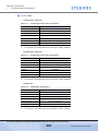
Related Manuals
Refer to the following related manuals in addition to this manual.
Manuals
Code
Description
ETERNUS DX60/DX80/DX90 Disk storage system
Setup Guide (Fibre Channel model)
P3AM-3082
This manual describes how
to ready Fibre Channel
model devices for operation.
ETERNUS DX60/DX80 Disk storage system Setup
Guide (iSCSI model)
P3AM-3092
This manual describes how
to ready iSCSI model
devices for operation.
ETERNUS DX60/DX80 Disk storage system Setup
Guide (SAS model)
P3AM-3102
This manual describes how
to ready SAS model devices
for operation.
ETERNUS DX60/DX80/DX90 Disk storage system
Safety Precautions
P3AM-3142
This manual describes the
points to note when
installing and operating the
device.
ETERNUS DX60/DX80/DX90 Disk storage system
Package Contents
P3AM-3062
This is the list of package
contents for the device and
optional products.
ETERNUS DX60/DX80/DX90 Disk storage system
Using Optional Products
P3AM-3152
This manual describes the
points to note when using
optional products.
ETERNUS DX60/DX80/DX90 Disk storage system
Feature activation licenses
P3AM-3312
This manual describes the
Advanced Copy license.
ETERNUS DX Disk storage systems Server Connection Guide
(Fibre Channel)*1
ETERNUS DX Disk storage systems Server Connection Guide (iSCSI)*1
ETERNUS DX Disk storage systems Server Connection Guide (SAS)*1
ETERNUS DX60/DX80/DX90 Web GUI User Guide
P2X0-0700
This manual describes how
to connect the ETERNUS
DX60/DX80/DX90 to a
server.
This manual describes how
to monitor and set the
ETERNUS DX60/DX80/
DX90 via Graphical User
Interface (GUI).
P3AM-3042-06ENZ0 ETERNUS DX60/DX80/DX90 Disk storage system User Guide
9
Copyright 2010 FUJITSU LIMITED
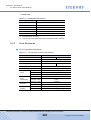
About this Manual
Manuals
Code
ETERNUS DX60/DX80/DX90 CLI User Guide
P2X0-0710
Description
This manual describes how
to monitor and set the
ETERNUS DX60/DX80/
DX90 via Command Line
Interface (CLI).
ETERNUS Multipath Driver V2.0 User's Guide
(For Windows®)
P2WW-1451
(For Linux)
P2U3-0031
(For AIX)
P2U3-0051
ETERNUS Multipath Driver V3.0 User's Guide
For Solaris™ Operating System
ETERNUS MPIO for IBM AIX V2.0.2
Installation & Configuration Guide for AIX
*1:
This manual describes how
to use the optional
ETERNUS Multipath Driver.
P2S0-0062
P2U3-0150
Download the necessary manuals for the customer operating environment (for server OS, Fibre
Channel card type, etc.) from the specified web-site. For the URL of the download web-site, refer to
the Documentation CD provided with the ETERNUS DX60/DX80/DX90.
P3AM-3042-06ENZ0 ETERNUS DX60/DX80/DX90 Disk storage system User Guide
10
Copyright 2010 FUJITSU LIMITED
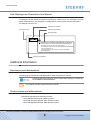
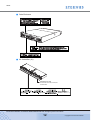
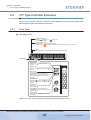
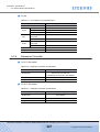
Labels
Warning labels and manufacturer's labels are found in various places of the ETERNUS DX60/
DX80/DX90, as shown in the example below.
Do not remove these labels.
■ Controller Enclosure
Manufacturer’s label
The label with the model, serial #, etc.
is located here.
P3AM-3042-06ENZ0 ETERNUS DX60/DX80/DX90 Disk storage system User Guide
11
Copyright 2010 FUJITSU LIMITED
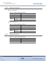
Labels
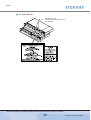
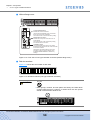
■ Drive Enclosure
■ AC Outlet Box (1U)
Manufacturer’s label
The label with the model, serial #, etc.
is located here.
P3AM-3042-06ENZ0 ETERNUS DX60/DX80/DX90 Disk storage system User Guide
12
Copyright 2010 FUJITSU LIMITED
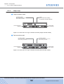
Labels
■ AC Outlet Box (2U)
Manufacturer’s label
The label with the model, serial #, etc.
is located here.
P3AM-3042-06ENZ0 ETERNUS DX60/DX80/DX90 Disk storage system User Guide
13
Copyright 2010 FUJITSU LIMITED
Contents
Chapter 1
1.1
1.2
1.2.1
1.2.2
1.2.3
1.2.4
1.2.5
1.2.6
1.3
1.3.1
1.3.2
1.3.3
1.3.4
1.3.5
1.3.6
1.3.7
1.3.8
System Features .............................................................................................. 22
Configuration .................................................................................................... 26
RAID Level ................................................................................................................................ 26
RAID Groups and Volumes ....................................................................................................... 32
System Disks ............................................................................................................................. 33
Hot Spare .................................................................................................................................. 34
Disks .......................................................................................................................................... 35
Host Interface ............................................................................................................................ 35
Functions .......................................................................................................... 36
Rebuild/Copyback ..................................................................................................................... 36
Redundant Copy ........................................................................................................................ 38
Advanced Copy ......................................................................................................................... 39
RAID Migration .......................................................................................................................... 42
Logical Device Expansion ......................................................................................................... 44
LUN Concatenation ................................................................................................................... 45
Security Functions ..................................................................................................................... 46
Eco-mode .................................................................................................................................. 48
Chapter 2
2.1
2.1.1
2.1.2
2.2
2.2.1
2.2.2
2.3
2.3.1
2.3.2
2.4
2.4.1
2.4.2
2.5
2.5.1
2.5.2
Components ...........................................................................49
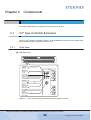
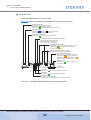
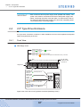
3.5" Type Controller Enclosure ........................................................................ 49
Front View ................................................................................................................................. 49
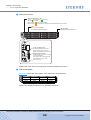
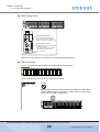
Rear View .................................................................................................................................. 51
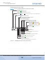
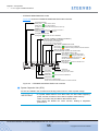
2.5" Type Controller Enclosure ........................................................................ 57
Front View ................................................................................................................................. 57
Rear View .................................................................................................................................. 59
3.5" Type Drive Enclosure ................................................................................ 63
Front View ................................................................................................................................. 63
Rear View .................................................................................................................................. 65
2.5" Type Drive Enclosure ................................................................................ 67
Front View ................................................................................................................................. 67
Rear View .................................................................................................................................. 69
AC Outlet Box .................................................................................................. 71
AC Outlet Box (1U) .................................................................................................................... 71
AC Outlet Box (2U) .................................................................................................................... 71
Chapter 3
3.1
3.2
Overview .................................................................................22
Standard Operations..............................................................72
Power ON Control ............................................................................................ 72
Power OFF Control .......................................................................................... 74
P3AM-3042-06ENZ0 ETERNUS DX60/DX80/DX90 Disk storage system User Guide
14
Copyright 2010 FUJITSU LIMITED
Contents
3.3
3.4
3.5
3.6
Attaching and Removing the Front Cover ........................................................ 75
Attaching and Removing the Flange Cover ..................................................... 78
Turning the AUTO POWER Switch On/Off ...................................................... 79
Wearing the Wrist Strap ................................................................................... 81
Chapter 4
Flow from Installation to Operation ......................................82
Chapter 5
Installation ..............................................................................86
5.1
5.1.1
5.1.2
5.2
5.2.1
5.2.2
5.2.3
5.2.4
Installation Preparation .................................................................................... 86
Placement Area ......................................................................................................................... 86
Check the Number of Wall Outlets ............................................................................................ 87
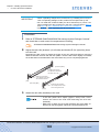
Rack Installation ............................................................................................... 88
Installing Controller Enclosure ................................................................................................... 91
Installing Drive Enclosure .......................................................................................................... 95
Installing AC Outlet Box (1U) ..................................................................................................... 99
Installing AC Outlet Box (2U) ................................................................................................... 102
Chapter 6
6.1
6.2
6.3
6.4
6.5
6.6
6.7
6.7.1
6.7.2
6.7.3
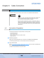
Connection Preparation ................................................................................. 106
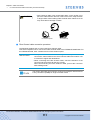
LAN Cable Connection (for Operation Management) .................................... 107
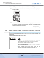
Fibre Channel Cable Connection (For Fibre Channel) ................................... 110
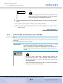
LAN Cable Connection (For iSCSI) ................................................................ 113
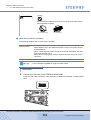
MiniSAS Cable Connection (For SAS) ........................................................... 115
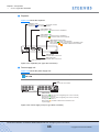
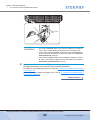
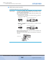
MiniSAS Cable Connection (For Drive Enclosures) ....................................... 117
Power Cord Connection ................................................................................. 123
With No AC Outlet Box ............................................................................................................ 124
When 1U AC Outlet Box is Installed ........................................................................................ 126
When 2U AC Outlet Box is Installed ........................................................................................ 131
Chapter 7
7.1
7.2
7.2.1
7.2.2
7.2.3
7.3
7.3.1
7.3.2
7.3.3
7.4
7.4.1
7.4.2
7.4.3
Cable Connection.................................................................106
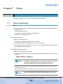
Setup .....................................................................................136
Setup Preparation .......................................................................................... 136
Basic Setup .................................................................................................... 139
Initial Setup .............................................................................................................................. 140
Configuration Wizard ............................................................................................................... 149
Hot Spare Registration ............................................................................................................ 160
Advanced Copy Setup ................................................................................... 163
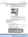
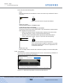
Obtaining the Advanced Copy License Key ............................................................................ 163
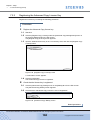
Registering the Advanced Copy License Key ......................................................................... 168
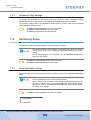
Advanced Copy Settings ......................................................................................................... 169
Monitoring Setup ............................................................................................ 169
Event Notification Setup .......................................................................................................... 169
E-mail Notification Setup ......................................................................................................... 172
ServerView (SNMP Trap Notification) Setup ........................................................................... 173
P3AM-3042-06ENZ0 ETERNUS DX60/DX80/DX90 Disk storage system User Guide
15
Copyright 2010 FUJITSU LIMITED
Contents
7.4.4
7.5
7.6
Remote Support Setup ............................................................................................................ 178
Server Connection Setup ............................................................................... 179
System Status Check ..................................................................................... 180
Chapter 8
8.1
8.1.1
8.1.2
8.1.3
8.1.4
8.2
8.2.1
8.2.2
8.2.3
8.2.4
Disk Installation .............................................................................................. 183
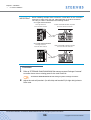
Disk Handling Instructions ....................................................................................................... 183
Installable Disks ....................................................................................................................... 184
Disk Installation Positions ........................................................................................................ 185
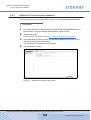
Additional Disk Installation Procedure ..................................................................................... 185
Drive Enclosure Installation ............................................................................ 191
Drive Enclosure Handling Instructions ..................................................................................... 191
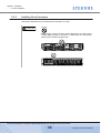
Installable Drive Enclosures .................................................................................................... 192
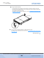
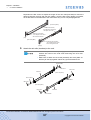
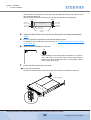
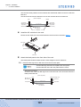
Drive Enclosure Rack Installation Procedure .......................................................................... 192
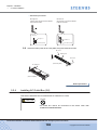
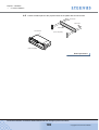
Additional Drive Enclosure Installation .................................................................................... 198
Chapter 9
9.1
9.2
9.3
9.3.1
9.4
9.4.1
9.4.2
9.4.3
9.5
9.5.1
9.5.2
Installing Optional Products ...............................................183
Operation and Maintenance ................................................201
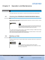
Checking the ETERNUS DX60/DX80/DX90 Status ....................................... 201
Backing up Data ............................................................................................. 201
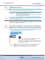
Maintenance Service ...................................................................................... 202
Maintenance Support Period ................................................................................................... 202
Post Start-of-Operation Changes to the Configuration .................................. 202
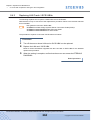
Replacing Fibre Channel Cards .............................................................................................. 203
Replacing LAN Cards / iSCSI HBAs ........................................................................................ 204
Replacing SAS Cards .............................................................................................................. 205
Troubleshooting ............................................................................................. 206
Check List ................................................................................................................................ 206
Trouble Record ........................................................................................................................ 213
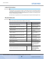
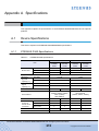
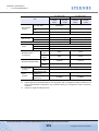
Appendix A Specifications .......................................................................215
A.1
A.1.1
A.1.2
A.1.3
A.2
A.2.1
A.2.2
A.2.3
A.2.4
A.2.5
A.2.6
Device Specifications ...................................................................................... 215
ETERNUS DX60 Specifications .............................................................................................. 215
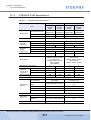
ETERNUS DX80 Specifications .............................................................................................. 217
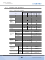
ETERNUS DX90 Specifications .............................................................................................. 219
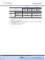
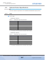
Optional Product Specifications ...................................................................... 221
Disks .......................................................................................................................................
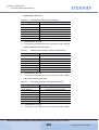
Drive Enclosures .....................................................................................................................
AC Outlet Box..........................................................................................................................
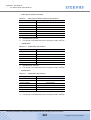
Expansion Controller ...............................................................................................................
Expansion Expander ...............................................................................................................
Extension Cable Kit .................................................................................................................
221
225
226
227
228
228
P3AM-3042-06ENZ0 ETERNUS DX60/DX80/DX90 Disk storage system User Guide
16
Copyright 2010 FUJITSU LIMITED
Contents
Appendix B Events detected by ServerView ..........................................229
Appendix C About Using of Open Sources ............................................230
Index
.......................................................................................................233
P3AM-3042-06ENZ0 ETERNUS DX60/DX80/DX90 Disk storage system User Guide
17
Copyright 2010 FUJITSU LIMITED
Figure of Contents
Figure 1.1
Figure 1.2
Figure 1.3
Figure 1.4
Figure 1.5
Figure 1.6
Figure 1.7
Figure 1.8
Figure 1.9
Figure 1.10
Figure 1.11
Figure 1.12
Figure 1.13
Figure 1.14
Figure 1.15
Figure 1.16
Figure 1.17
Figure 1.18
Figure 1.19
Figure 1.20
Figure 2.1
Figure 2.2
Figure 2.3
Figure 2.4
Figure 2.5
Figure 2.6
Figure 2.7
Figure 2.8
Figure 2.9
Figure 2.10
Figure 2.11
Figure 2.12
Figure 2.13
Figure 2.14
Figure 2.15
Figure 2.16
Figure 2.17
Figure 2.18
Figure 2.19
Figure 2.20
Figure 2.21
Figure 2.22
Figure 2.23
Figure 2.24
Figure 2.25
Figure 2.26
Figure 2.27
Figure 2.28
RAID0 concept ..........................................................................................................................
RAID1 concept ..........................................................................................................................
RAID1+0 concept ......................................................................................................................
RAID5 concept ..........................................................................................................................
RAID5+0 concept ......................................................................................................................
RAID6 concept ..........................................................................................................................
Example of a RAID group..........................................................................................................
RAID group concept ..................................................................................................................
Hot Spares.................................................................................................................................
Rebuild/Copyback function........................................................................................................
Redundant Copy Function.........................................................................................................
Example of an Advanced Copy operation .................................................................................
Example for use RAID Migration 1 ............................................................................................
Example for use RAID Migration 2 ............................................................................................
Example for use Logical Device Expansion ..............................................................................
Example for use LUN Concatenation ........................................................................................
LUN Mapping function ...............................................................................................................
Host Affinity function..................................................................................................................
Eco-mode mechanism...............................................................................................................
Setting example for Eco-mode schedule...................................................................................
Front view of 3.5" type controller enclosure (with front cover)...................................................
Front view of 3.5" type controller enclosure (without front cover)..............................................
Disk slot numbers (3.5" type controller enclosure) ....................................................................
Rear view of 3.5" type controller enclosure (single controller model)........................................
Rear view of 3.5" type controller enclosure (dual controller model) ..........................................
ETERNUS DX60/DX80 Fibre Channel model controller ...........................................................
ETERNUS DX90 Fibre Channel model controller .....................................................................
ETERNUS DX60/DX80 iSCSI model controller.........................................................................
ETERNUS DX60/DX80 SAS model controller...........................................................................
Power supply unit (3.5" type controller enclosure) ....................................................................
Front view of 2.5" type controller enclosure (with flange cover) ................................................
Front view of 2.5" type controller enclosure (without flange cover) ...........................................
Disk slot numbers (2.5" type controller enclosure) ....................................................................
Rear view of 2.5" type controller enclosure (single controller model)........................................
Rear view of 2.5" type controller enclosure (dual controller model) ..........................................
ETERNUS DX60/DX80 Fibre Channel model controller ...........................................................
ETERNUS DX90 Fibre Channel model controller .....................................................................
Power supply unit (2.5" type controller enclosure) ....................................................................
Front view of 3.5" type drive enclosure (with front cover)..........................................................
Front view of 3.5" type drive enclosure (without front cover).....................................................
Disk slot numbers of 3.5" type drive enclosure..........................................................................
Rear view of 3.5" type drive enclosure (single expander model)...............................................
Rear view of 3.5" type drive enclosure (dual expander model) .................................................
Expander (3.5" type drive enclosure) ........................................................................................
Power supply unit (3.5" type drive enclosure) ...........................................................................
Front view of 2.5" type drive enclosure (with flange cover) .......................................................
Front view of 2.5" type drive enclosure (without flange cover) ..................................................
Disk slot numbers of 2.5" type drive enclosure..........................................................................
27
27
28
28
29
30
32
32
34
36
38
39
42
43
44
45
46
47
48
48
49
50
50
51
51
52
53
54
55
56
57
58
58
59
59
60
61
62
63
64
64
65
65
66
66
67
68
68
P3AM-3042-06ENZ0 ETERNUS DX60/DX80/DX90 Disk storage system User Guide
18
Copyright 2010 FUJITSU LIMITED
Figure of Contents
Figure 2.29
Figure 2.30
Figure 2.31
Figure 2.32
Figure 2.33
Figure 2.34
Figure 3.1
Figure 5.1
Figure 6.1
Figure 6.2
Figure 6.3
Figure 6.4
Figure 6.5
Figure 6.6
Figure 7.1
Figure 7.2
Figure 7.3
Figure 7.4
Figure 7.5
Figure 7.6
Figure 7.7
Figure 7.8
Figure 7.9
Figure 7.10
Figure 7.11
Figure 7.12
Figure 7.13
Figure 7.14
Figure 7.15
Figure 7.16
Figure 7.17
Figure 7.18
Figure 7.19
Figure 7.20
Figure 7.21
Figure 7.22
Figure 7.23
Figure 7.24
Figure 7.25
Figure 7.26
Figure 7.27
Figure 7.28
Figure 7.29
Figure 7.30
Figure 7.31
Figure 7.32
Figure 7.33
Figure 7.34
Figure 7.35
Figure 7.36
Rear view of 2.5" type drive enclosure (single expander model)............................................... 69
Rear view of 2.5" type drive enclosure (dual expander model) ................................................. 69
Expander (2.5" type drive enclosure) ........................................................................................ 70
Power supply unit (2.5" type drive enclosure) ........................................................................... 70
AC outlet box (1U) ..................................................................................................................... 71
AC outlet box (2U) ..................................................................................................................... 71
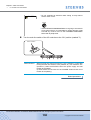
Wrist strap ................................................................................................................................. 81
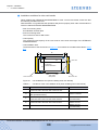
Unit installation area (when installing other rack brands) .......................................................... 89
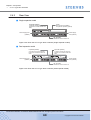
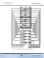
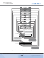
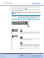
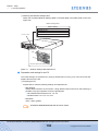
MiniSAS cable connection (between the controller enclosure and drive enclosure)
(single controller model) .......................................................................................................... 120
MiniSAS cable connection (between the controller enclosure and drive enclosure)
(dual controller model)............................................................................................................. 120
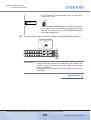
MiniSAS cable connection (When two or more drive enclosures are added)
(single controller model) .......................................................................................................... 122
MiniSAS cable connection (When two or more drive enclosures are added)
(dual controller model)............................................................................................................. 122
Connection of AC output cables (1U AC outlet box) ............................................................... 128
Connection of AC output cables (2U AC outlet box) ............................................................... 133
Network Settings label attachment .......................................................................................... 138
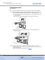
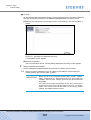
Start screen of the [Initial Setup] function................................................................................ 141
[Set Date and Time] screen..................................................................................................... 142
[Set Storage System Name] screen ........................................................................................ 143
[Change Password] screen ..................................................................................................... 143
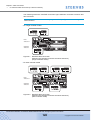
[Modify FC Port Mode] screen................................................................................................. 144
[Set FC Port Parameters] screen (for the "FC-CA" Port Mode)............................................... 145
[Set iSCSI Port Parameters] screen ........................................................................................ 146
[Set SAS Port Parameters] screen .......................................................................................... 147
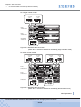
[Setup Network Environment] screen ...................................................................................... 148
[Finish] screen of the initial setup ............................................................................................ 149
Configuration Wizard initial screen .......................................................................................... 150
[Create RAID Group] screen ................................................................................................... 152
[Create Volume] screen........................................................................................................... 153
[Setup FC Host] screen ........................................................................................................... 154
[Setup iSCSI Host] screen....................................................................................................... 155
[Setup SAS Host] screen......................................................................................................... 156
[Configure Affinity Group] screen ............................................................................................ 157
[Define LUN Mapping] screen 1 (when the Host Affinity function is used) .............................. 158
[Define LUN Mapping] screen 2 (when the Host Affinity function is used) .............................. 158
[Define LUN Mapping] screen 1 (when the Host Affinity function is not used) ........................ 159
[Define LUN Mapping] screen 2 (when the Host Affinity function is not used) ........................ 159
[Assign Hot Spare] screen....................................................................................................... 162
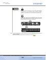
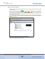
Display location of the serial number (GUI screen) ................................................................. 164
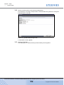
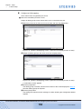
Advanced Copy Feature License Key Web Screen 1 ............................................................. 165
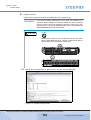
Advanced Copy Feature License Key Web Screen 2 ............................................................. 165
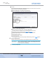
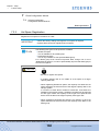
Advanced Copy Feature License Key Web Screen 3 ............................................................. 166
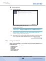
[Register Copy License] screen............................................................................................... 168
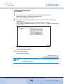
[Advanced Copy Status] screen .............................................................................................. 168
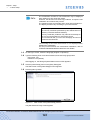
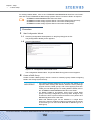
[Setup Event Notification] screen (Setting based on Severity) ................................................ 170
[Setup Event Notification] screen (Error Severity Level) ......................................................... 170
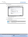
[Setup Event Notification] screen (Warning Level) .................................................................. 171
[Setup Event Notification] screen (Informational Level)........................................................... 171
[Setup E-Mail Notification] screen (Notification E-Mail) ........................................................... 172
[Setup E-Mail Notification] screen (Mail Server Settings)........................................................ 173
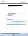
Send Test E-mail ..................................................................................................................... 173
P3AM-3042-06ENZ0 ETERNUS DX60/DX80/DX90 Disk storage system User Guide
19
Copyright 2010 FUJITSU LIMITED
Figure of Contents
Figure 7.37
Figure 7.38
Figure 7.39
Figure 7.40
Figure 7.41
Figure 7.42
Figure 7.43
Figure 7.44
Figure 8.1
Figure 8.2
Figure 8.3
Figure 8.4
Figure 8.5
Figure 9.1
Figure 9.2
Figure 9.3
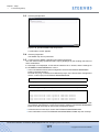
[Setup Network Environment] screen (when ServerView is running) ......................................
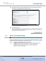
[Trap] screen ...........................................................................................................................
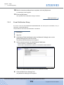
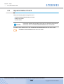
[Download MIB File] screen.....................................................................................................
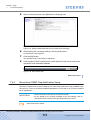
[Perform SNMP Trap Test] screen ..........................................................................................
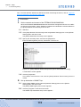
[Setup Remote Support] screen ..............................................................................................
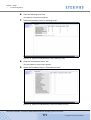
Storage System Status screen ................................................................................................
RAID Group Status screen ......................................................................................................
Volume Status screen .............................................................................................................
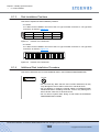
Position of 3.5" disk slots.........................................................................................................
Position of 2.5" disk slots.........................................................................................................
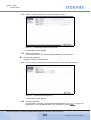
[Add Drive Enclosure] initial screen.........................................................................................
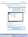
[Add Drive Enclosure] - Workflow Sequence screen 1............................................................
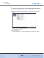
[Add Drive Enclosure] - Workflow Sequence screen 2............................................................
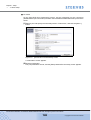
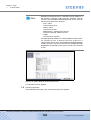
ETERNUS Multipath Manager Window...................................................................................
Trouble record (1/2).................................................................................................................
Trouble record (2/2).................................................................................................................
174
175
176
177
179
181
182
182
185
185
198
199
200
211
213
214
P3AM-3042-06ENZ0 ETERNUS DX60/DX80/DX90 Disk storage system User Guide
20
Copyright 2010 FUJITSU LIMITED
Table of Contents
Table 1.1
Table 1.2
Table 1.3
Table 1.4
Table 1.5
Table 1.6
Table 1.7
Table 1.8
Table 1.9
Table 1.10
Table 5.1
Table 5.2
Table 5.3
Table 5.4
Table 6.1
Table 6.2
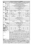
Table A.1
Table A.2
Table A.3
Table A.4
Table A.5
Table A.6
Table A.7
Table A.8
Table A.9
Table A.10
Table A.11
Table A.12
Table A.13
Table A.14
Table A.15
Table A.16
Table A.17
Table A.18
Table A.19
Table A.20
Table A.21
Table A.22
Table A.23
Table A.24
Table B.1
User capacity per disk ............................................................................................................... 30
Formula for calculating user capacity for each RAID level ........................................................ 31
User capacity for each RAID level............................................................................................. 31
Recommended number of disks per RAID group...................................................................... 32
The maximum number of volumes that can be set.................................................................... 33
Volume formatting time (for SAS disks and Nearline SAS disks) ............................................. 33
Rebuild process times (for SAS disks and Nearline SAS disks) ............................................... 37
Copyback process times (for SAS disks and Nearline SAS disks)............................................ 37
Available copy functions ............................................................................................................ 41
Maximum number of copy sessions .......................................................................................... 41
Wall outlets and cable lengths................................................................................................... 87
Required number of power outlets (when AC outlet boxes are not connected) ........................ 87
Required number of power outlets (when AC outlet boxes are connected) .............................. 88
Conditions of the unit installation area (when installing other rack brands)............................... 89
Connection path of a power cord (AC output cable) (AC outlet box (1U))............................... 127
Connection path of a power cord (AC output cable) (AC outlet box (2U))............................... 132
ETERNUS DX60 specifications............................................................................................... 215
ETERNUS DX80 specifications............................................................................................... 217
ETERNUS DX90 specifications............................................................................................... 219
300GB/15krpm SAS disk specifications .................................................................................. 221
450GB/15krpm SAS disk specifications .................................................................................. 221
600GB/15krpm SAS disk specifications .................................................................................. 222
750GB/7.2krpm Nearline SAS disk specifications................................................................... 222
1TB/7.2krpm Nearline SAS disk specifications ....................................................................... 222
2TB/7.2krpm Nearline SAS disk specifications ....................................................................... 223
100GB SSD specifications ...................................................................................................... 223
200GB SSD specifications ...................................................................................................... 223
146GB/10krpm SAS disk specifications .................................................................................. 224
300GB/10krpm SAS disk specifications .................................................................................. 224
100GB SSD specifications ...................................................................................................... 224
200GB SSD specifications ...................................................................................................... 225
3.5" type drive enclosure specifications................................................................................... 225
2.5" type drive enclosure specifications................................................................................... 226
AC outlet box (1U) specifications ............................................................................................ 226
AC outlet box (2U) specifications ............................................................................................ 227
Expansion controller specifications ......................................................................................... 227
Expansion controller specifications ......................................................................................... 227
Expansion expander specifications ......................................................................................... 228
Expansion expander specifications ......................................................................................... 228
Extension cable kit specifications ............................................................................................ 228
ServerView event list ............................................................................................................... 229
P3AM-3042-06ENZ0 ETERNUS DX60/DX80/DX90 Disk storage system User Guide
21
Copyright 2010 FUJITSU LIMITED
Chapter 1
Overview
This chapter provides an overview of the ETERNUS DX60/DX80/DX90 features, and specifications.
1.1
System Features
Special features of the ETERNUS DX60/DX80/DX90 are shown below:
■ Space and Energy Savings
•
Compact design makes effective use of rack space
- Three models are available; ETERNUS DX60, ETERNUS DX80, and ETERNUS DX90. All
models are compactly-designed to use rack space efficiently, coming in 2U size (*1)
enclosures.
*1:
2U = Two 19-inch rack units = 88mm device height
- Two types of controller enclosure and drive enclosures (optional) are available; those for
3.5" disks and those for 2.5" disks.
Up to twelve 3.5" disks can be installed in the 3.5" type enclosures, and up to twenty-four
2.5" disks can be installed in the 2.5" type enclosures. The appropriate drive configuration
should be decided based on the purpose, applications and onsite installation space available for the ETERNUS DX60/DX80/DX90.
- Up to 24 disks can be installed in the ETERNUS DX60 and up to 120 disks in the ETERNUS DX80/DX90.
•
Energy savings by the latest technology
Power efficiency and energy savings are achieved with advanced technology.
•
Eco-mode to reduce environmental load
Using the Eco-mode function to start and stop the spindle rotation in the disk for each RAID
group during the specified hour. Stop the spindle rotation when there is no access to the disk
to reduce power consumption and decrease environmental load.
•
Visualization of power consumption and ambient temperature
Power consumption and ambient temperature for the entire ETERNUS DX60/DX80/DX90
can be checked using the (optional) "ETERNUS SF Storage Cruiser" integrated management
software's Graphical User Interface (GUI). Both current status and historical records (for a
day, a week, or an year) can be displayed.
P3AM-3042-06ENZ0 ETERNUS DX60/DX80/DX90 Disk storage system User Guide
22
Copyright 2010 FUJITSU LIMITED
Chapter 1 Overview
>
1.1 System Features
■ Easy Installation and Operation Management
•
Settings of the ETERNUS DX60/DX80/DX90 and its operation management can be
performed by GUI that uses a Web browser (hereafter referred to as "GUI"), or CLI that uses
commands and command scripts.
Settings required for the ETERNUS DX60/DX80/DX90 initial installation can be easily
performed by following the GUI wizard and inputting parameters for displayed setting items.
The ETERNUS DX60/DX80/DX90 can be configured, and its status can be displayed and
monitored using GUI or CLI.
•
ETERNUS SF Express
ETERNUS SF Express is a storage system introduction and operation support software for
the user who had put off the introduction of the storage system up to now because of
"Difficulty" and "Introduction and operation cost increase".
ETERNUS SF Express is an easy to use software addition to ETERNUS DX Disk storage
system, in order to facilitate management of ETERNUS DX Disk storage system as well as
leverage ETERNUS DX Disk storage system functionality like Snapshots, Cloning or
Replication.
For details of ETERNUS SF Express and how to download it, refer to the following web-site:
http://www.fujitsu.com/global/support/computing/storage/software/esf-express.html
■ High scalability and versatile connectivity
•
Utilizes the latest disk technology
Both 3.5" SAS disks (*1) (300GB/450GB/600GB; 15,000rpm), and 2.5" SAS disks (*1) (146GB/
300GB; 10,000rpm) are available.
For data backup and archival purposes the ETERNUS DX60/DX80/DX90 is able to use large
capacity, highly cost effective 3.5" Nearline SAS disks (*1) (750GB/1TB/2TB; 7,200rpm).
Flash memory based 3.5" SSDs (*2) (100GB/200GB) and 2.5" SSDs (*2) (100GB/200GB) are
also available (except for the ETERNUS DX60, which does not support SSDs).
*1:
*2:
•
SAS: Serial Attached SCSI
SSD: Solid State Drive
Supports capacity expansion during system operation
- Disks and drive enclosures can be added during the system operation.
- RAID group capacity can be expanded by adding disk from the unit of one.
- Volume can be expanded during the system operation. Even when the work load
increased rapidly, the ETERNUS DX60/DX80/DX90 flexibly expand the volume capacity
with no interruption of the operation.
•
High connectivity supports the multi-platform environment
- FC-SAN, IP-SAN, and DAS environments are supported, with Fibre Channel (maximum
transfer speed: 8Gbit/s), iSCSI (maximum transfer speed: 1Gbit/s), and SAS (maximum
transfer speed: 3Gbit/s) host interfaces being used, respectively.
P3AM-3042-06ENZ0 ETERNUS DX60/DX80/DX90 Disk storage system User Guide
23
Copyright 2010 FUJITSU LIMITED
Chapter 1 Overview
>
1.1 System Features
- The ETERNUS DX60/DX80/DX90 supports multiple Operating Systems such as UNIX,
Linux, Windows®, and VMware®, and can be connected as a storage system for
PRIMEQUEST, SPARC Enterprise, PRIMERGY servers as well as for UNIX/IA servers of
other companies. Also the RAID aggregation using SAN (Storage Area Network) is
available.
■ Data integrity with high-speed backup
•
Nearline SAS disks for data backup and archiving
- Using large capacity / cost effective Nearline SAS disks allows low cost D2D (Disk to Disk)
backup and high-speed recovery in the case of unexpected failure.
- Storing the less frequently accessed data such as archive data in the Nearline SAS disks
allows easy reading. Nearline SAS disks and SAS disks can be installed in the same drive
enclosure.
•
Backup function
Using the Advanced Copy function allows the high-speed copying of disk volumes at any
given time.
•
Data integrity against disasters
Using the Remote Advanced Copy functions (enhanced Advanced Copy functions), data can
be copied between multiple ETERNUS DX90s without burdening the server. In addition, using
the Extended Remote Advanced Copy functions, data can be copied between ETERNUS
DX90s in the remote place that are connected with SAN-WAN-SAN topology, which enables
duplication of database and backup to a remote place in the case of disaster.
■ High reliability supports 24/7/365 operation
•
Duplication of important components
Important components such as controllers (for dual-controller model), power supply units, and
fans are duplicated to continue the operation in the case of unexpected failure. Also this
allows the hot swapping of failed components with the device power on. In addition, the latest
firmware can be applied during system operation.
•
Various supported RAID levels
The ETERNUS DX60/DX80/DX90 supports RAID5+0 that is superior to RAID5 in reliability
and performance, and RAID6 that responds to the double failure of disks, as well as RAID1,
RAID1+0, and RAID5. A flexible RAID configuration can be selected.
•
Redundant copy ensures disk redundancy
The ETERNUS DX60/DX80/DX90 diagnostic routines test the disks in order to predict failures
before they happen. When a disk requires preventive maintenance, a hot spare is
automatically switched in to replace it, providing continued data redundancy and stable
operation.
•
Block Guard ensures data integrity
The ETERNUS DX60/DX80/DX90 adds check codes and check them at multiple checkpoints
on data transfer path to ensure the data integrity.
P3AM-3042-06ENZ0 ETERNUS DX60/DX80/DX90 Disk storage system User Guide
24
Copyright 2010 FUJITSU LIMITED
Chapter 1 Overview
>
1.1 System Features
•
System Capacitor Unit (SCU)
A SCU that does not need to be regularly replaced is installed as a backup power source in
case of a power failure. If the power fails, the SCU enables the cache memory data to be
saved to flash memory. Therefore, unlike a battery, the SCU does not have a time limit to save
data. The SCU is charged so quickly that write performance is recovered right after power
recovery.
■ E-mail notification
If an error occurs in the ETERNUS DX60/DX80/DX90, the details can be sent to a specified email address.
■ Strengthening security against information leaks
•
Data encryption to prevent information leaks
Data can be encrypted and written. Data encryption can prevent information leaks caused by
fraudulent decoding even if the disk is stolen.
Data encryption may not be possible for some configurations.
•
Protection against fraudulent access
The ETERNUS DX60/DX80/DX90 supports SSL/SSH that encrypts and communicates
information on the network. This protects against malicious use of data and fraudulent access
to devices via a Web browser (GUI) or CLI.
■ RoHS compliance
The ETERNUS DX60/DX80/DX90 complies with RoHS, as mandated by the Council of Europe
and our board of directors. RoHS limits the use in electric and electronic equipment of six specific
chemicals: lead, hexavalent chromium, mercury, cadmium, PBB (polybrominated biphenyl), and
PBDE (polybrominated diphenyl ether). In addition, lead-free soldering is used for all printed-wiring boards.
P3AM-3042-06ENZ0 ETERNUS DX60/DX80/DX90 Disk storage system User Guide
25
Copyright 2010 FUJITSU LIMITED
Chapter 1 Overview
>
1.2 Configuration
1.2
Configuration
This chapter describes items to be noted before configuring the ETERNUS DX60/DX80/DX90
systems.
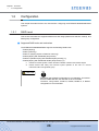
1.2.1
RAID Level
This section describes the supported RAID level and usage (RAID level selection criteria), and
RAID group configuration.
■ Supported RAID levels and mechanism
The ETERNUS DX60/DX80/DX90 supports the following RAID levels.
•
•
•
•
•
•
RAID0 (striping)
RAID1 (mirroring)
RAID1+0 (striping of pairs of disks for mirroring)
RAID5 (striping with distributed parity blocks)
RAID5+0 (double striping with distributed parity blocks) (*1)
RAID6 (striping with distributed double parity blocks) (*2)
*1:
*2:
RAID5+0 is a RAID system in which the data on RAID5 volumes is then RAID0 striped.
RAID6 ensures data safety and continues system operation in the case of a second
malfunction within a single RAID group.
CAUTION
Do
• Remember that a RAID0 configuration is not redundant. This means
that if a RAID0 disk fails, the data will not be recoverable.
Therefore, using RAID1, RAID1+0, RAID5, RAID5+0, or RAID6
configuration is recommended.
P3AM-3042-06ENZ0 ETERNUS DX60/DX80/DX90 Disk storage system User Guide
26
Copyright 2010 FUJITSU LIMITED
Chapter 1 Overview
>
1.2 Configuration
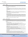
Each RAID level description is shown below.
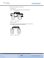
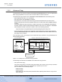
•
RAID0 (striping)
Data is split in unit of blocks and stored across multiple disks.
Data writing request
A
C
D
A
B
C
D
HDD0
HDD1
Figure 1.1
•
B
RAID0 concept
RAID1 (mirroring)
RAID1 stores the same data on two duplicated disks at the same time.
If one disk fails, other disk continues operation.
Data writing request
A
B
C
D
A
A
B
B
C
C
D
D
HDD0
HDD1
Figure 1.2
RAID1 concept
P3AM-3042-06ENZ0 ETERNUS DX60/DX80/DX90 Disk storage system User Guide
27
Copyright 2010 FUJITSU LIMITED
Chapter 1 Overview
>
1.2 Configuration
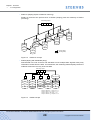
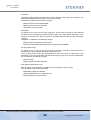
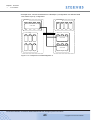
•
RAID1+0 (striping of pairs of disks for mirroring)
RAID1+0 combines the performance of RAID0 (striping) with the reliability of RAID1
(mirroring).
Data writing request
A
B
C
D
D
D’
C
Mirroring
HDD3
C’
B
HDD7
Mirroring
HDD2
B’
A
HDD6
Mirroring
HDD1
A’
HDD5
Mirroring
Striping (RAID0)
HDD0
Mirroring (RAID1)
HDD4
Figure 1.3
•
RAID1+0 concept
RAID5 (striping with distributed parity)
Data divided into units of blocks and allocated across multiple disks together with parity
information created from the data. If one disk fails, the remaining data and parity blocks are
sufficient to allow the recovery of the lost data.
Data writing request
A
B
C
D
A
B
C
D
A
B
C
D
P A, B, C, D
E
F
G
P E, F, G, H
H
Create Parity Data
I
J
P I, J, K, L
K
L
M
P M, N, O, P
N
O
P
HDD0
HDD1
HDD2
HDD3
Parity for data A to D
Parity for data E to H
Parity for data I to L:
Parity for data M to P
Figure 1.4
HDD4
Parity A, B, C, D
Parity E, F, G, H
Parity I, J, K, L
Parity M, N, O, P
RAID5 concept
P3AM-3042-06ENZ0 ETERNUS DX60/DX80/DX90 Disk storage system User Guide
28
Copyright 2010 FUJITSU LIMITED
Chapter 1 Overview
>
1.2 Configuration
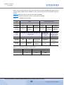
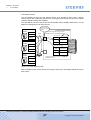
•
RAID5+0 (double striping with distributed parity)
Multiple RAID5 volumes are RAID0 striped. For large capacity configurations, use of
RAID5+0 instead of RAID5 results in enhanced performance, improved reliability, and shorter
rebuilding times.
Data writing request
A
B
C
D
Striping (RAID0)
A
B
C
D
A
C
B
D
Striping with
distributed parity
(RAID5)
B
Create parity data
A
B
P A, B
E
P E, F
F
P I, J
I
J
P K, L
M
N
P M, N
O
P
P O, P
HDD0
HDD1
HDD2
HDD3
HDD4
HDD5
A
RAID5
D
Create parity data
C
D
P C, D
G
P G, H
H
K
L
C
RAID5
Striping (RAID0)
Striping with
distributed parity
(RAID5)
Figure 1.5
RAID5+0 concept
P3AM-3042-06ENZ0 ETERNUS DX60/DX80/DX90 Disk storage system User Guide
29
Copyright 2010 FUJITSU LIMITED
Chapter 1 Overview
>
1.2 Configuration
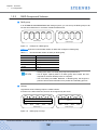
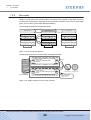
•
RAID6 (striping with distributed double parities)
Store two different parities on different disks (double parities) to recover from up to two disk
failures.
Data writing request
A
B
C
D
A
B
C
D
A
B
C
D
P1 A, B, C, D
P2 A, B, C, D
E
F
G
P1 E, F, G, H
P2 E, F, G, H
H
I
J
P1 I, J, K, L
P2 I, J, K, L
K
L
M
P1 M, N, O, P
P2 M, N, O, P
N
O
P
HDD0
HDD1
HDD2
HDD3
HDD4
HDD5
Create parity data
Parity for data A to D: Parity1 A, B, C, D and Parity2 A, B, C, D
Parity for data E to H: Parity1 E, F, G, H and Parity2 E, F, G, H
Parity for data I to L: Parity1 I, J, K, L and Parity2 I, J, K, L
Parity for data M to P: Parity1 M, N, O, P and Parity2 M, N, O, P
Figure 1.6
RAID6 concept
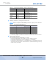
■ User capacity for each RAID level
User capacity varies according to the RAID level.
Table 1.1 shows the user capacity per disk. Table 1.2 shows the formula for calculating the user
capacity for each RAID level.
Table 1.1
User capacity per disk
Product name
User Capacity per Disk (*1)
100GB SSD
92,672MB
200GB SSD
186,624MB
146GB SAS disk
135,936MB
300GB SAS disk
279,040MB
450GB SAS disk
419,072MB
600GB SAS disk
559,104MB
750GB Nearline SAS disk
702,976MB
1TB Nearline SAS disk
937,728MB
2TB Nearline SAS disk
1,866,240MB
*1:
The above User Capacities are based on a 1MB = 1,0242Byte metric.
P3AM-3042-06ENZ0 ETERNUS DX60/DX80/DX90 Disk storage system User Guide
30
Copyright 2010 FUJITSU LIMITED
Chapter 1 Overview
>
1.2 Configuration
Table 1.2
Formula for calculating user capacity for each RAID level
RAID level
Number of disks (*1)
Formula for user capacity computation
RAID0
2 to 16
Disk capacity × Number of disks
RAID1
2
Disk capacity × Number of disks/2
RAID1+0
4 to 32
Disk capacity × Number of disks/2
RAID5
3 to 16
Disk capacity ×
(Number of disks - 1)
RAID5+0
6 to 32
Disk capacity ×
(Number of disks - 2)
RAID6
5 to 16
Disk capacity ×
(Number of disks - 2)
*1:
Actual number of disks can be installed depend on the models.
■ Reliability, performance, capacity for each RAID level
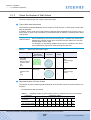
Table 1.3 shows the comparison result of reliability, performance, capacity for each RAID level.
Table 1.3
User capacity for each RAID level
RAID level
Reliability
Performance
(Writing speed) (*1)
Capacity
RAID0
Bad
Very Good
Very Good
RAID1
Good
Good
Not Bad
RAID1+0
Good
Very Good
Not Bad
RAID5
Good
Good
Good
RAID5+0
Good
Good
Good
Very Good
Good
Good
RAID6
*1:
Performance may differ according to the number of disks and the processing method from the host.
■ Recommended RAID level
Select the appropriate RAID level according to the usage.
• Recommended RAID level is RAID1, RAID1+0, RAID5, RAID5+0 and RAID6.
• For read and write performance, RAID1+0 configuration is recommended.
• For read only file servers and backup servers, RAID5, RAID5+0, or RAID6 can also be used.
However, if the disk fails, note that data restoration from parities and rebuilding process may
result in a loss in performance.
P3AM-3042-06ENZ0 ETERNUS DX60/DX80/DX90 Disk storage system User Guide
31
Copyright 2010 FUJITSU LIMITED
Chapter 1 Overview
>
1.2 Configuration
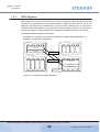
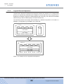
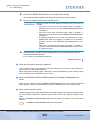
1.2.2
RAID Groups and Volumes
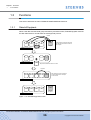
■ RAID group
In an ETERNUS DX60/DX80/DX90 Disk storage system, you can set up the RAID groups to all
use the same RAID level or a mixture of different RAID levels.
RAID Group 1
Figure 1.7
RAID Group 2
Example of a RAID group
Table 1.4 show the recommended number of disks that configures a RAID group.
Table 1.4
Recommended number of disks per RAID group
RAID level
RAID1
Recommended number of disks
2
RAID1+0
4, 6, 8, 10
RAID5
3, 4, 5, 6
RAID5+0
6, 8, 10, 12
RAID6
5, 6, 7
• Adding more disks to a RAID group improves performance.
• Use of higher capacity disks in a RAID group will increase the time
required for the disk rebuild process to complete.
• The more disks per RAID5, RAID5+0, or RAID6 group, the longer the
period of time for data restoration from parities and rebuilding process.
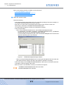
■ Volume
Logical disk areas in RAID groups are called volumes.
A volume is the basic RAID unit, that can be recognized by the server.
Volume 1
Volume 3
Volume 2
RAID Group 1
Figure 1.8
RAID Group 2
RAID group concept
P3AM-3042-06ENZ0 ETERNUS DX60/DX80/DX90 Disk storage system User Guide
32
Copyright 2010 FUJITSU LIMITED
Chapter 1 Overview
>
1.2 Configuration
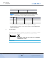
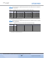
• Table 1.5 shows the maximum number of volumes that can be set.
Table 1.5
The maximum number of volumes that can be set
Model
Per RAID group
Per storage system
ETERNUS DX60
Max. 128
Max. 512
ETERNUS DX80/DX90
Max. 128
Max. 1,024
• Table 1.6 shows the time for volume formatting (when the volume capacity is 100GB).
Table 1.6
RAID
level
Volume formatting time (for SAS disks and Nearline SAS disks)
No. of
disks
Time required for volume formatting (*1)
3.5" SAS disks
2.5" SAS disks
Nearline SAS disks
RAID1
2
Approx. 35 minutes/100GB
Approx. 40 minutes/100GB
Approx. 73 minutes/100GB
RAID1+0
8
Approx. 25 minutes/100GB
Approx. 30 minutes/100GB
Approx. 43 minutes/100GB
RAID5
5
Approx. 25 minutes/100GB
Approx. 25 minutes/100GB
Approx. 49 minutes/100GB
RAID5+0
6
Approx. 25 minutes/100GB
Approx. 30 minutes/100GB
Approx. 43 minutes/100GB
RAID6
6
Approx. 30 minutes/100GB
Approx. 40 minutes/100GB
Approx. 58 minutes/100GB
*1:
The value shows the time required for volume formatting when the volume capacity is 100GB and
there is no server I/O. The time depends on the disk configuration or the disk type.
• No more than 8TB can be used for any one volume. However, the maximum allowed volume
capacity is OS dependent.
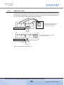
1.2.3
System Disks
System disks are disks which have part of their area assigned for use by the system (the system
area), and two system disks are installed in Slot0 and Slot1 in the controller enclosure.
WARNING
Do Not
• Do not remove system disks. Doing so will render the ETERNUS
DX60/DX80/DX90 unusable.
IMPORTANT
System disks cannot be registered as hot spares.
P3AM-3042-06ENZ0 ETERNUS DX60/DX80/DX90 Disk storage system User Guide
33
Copyright 2010 FUJITSU LIMITED
Chapter 1 Overview
>
1.2 Configuration
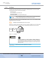
1.2.4
Hot Spare
Hot spares are used as spare disks for when disks in a RAID group fail, or are in error status.
The following two types of hot spare are available:
• Global Hot spare
This is available for any RAID group.
• Dedicated Hot spare
This is only available to one specified RAID group.
Assign "Dedicated Hot spares" to RAID groups that contain important data,
in order to preferentially improve their access to hot spares.
For details about Global Hot spare and Dedicated Hot spare, refer to the "ETERNUS DX60/
DX80/DX90 Web GUI User Guide".
"ETERNUS DX60/DX80/DX90 Web GUI User Guide"
Refer
Make sure to register sufficient hot spares. If a free hot spare is available, when one of the RAID
group disks has a problem, data from this disk is automatically replicated into the hot spare.
User Disk
User Disk
User Disk
Hot Spare
Failure
Figure 1.9
Hot Spares
CAUTION
Do
• If a disk configured in a RAID1, RAID1+0, RAID5, RAID5+0, or
RAID6 group fails, contact your maintenance engineer immediately
as the failed disk should be replaced at once. If another disk fails
before the first disk that failed is replaced, the data of the second
disk may be lost.
IMPORTANT
System disks cannot be registered as hot spares.
P3AM-3042-06ENZ0 ETERNUS DX60/DX80/DX90 Disk storage system User Guide
34
Copyright 2010 FUJITSU LIMITED
Chapter 1 Overview
>
1.2 Configuration
1.2.5
Disks
Three kinds of drives can be installed in the device: SAS disks, Nearline SAS disks, and SSDs.
Each is suitable for the following usage cases:
• SAS Disk
SAS disks are highly-performance/high-reliability disks for enterprise use. SAS disks support
24/7/365 operations and are used to store high performance databases and other frequently
accessed data.
2.5" SAS disks take less space, consume less electrical power, and are lighter than 3.5" SAS
disks.
• Nearline SAS Disk
Nearline SAS disks are high capacity / cost effective disks for data backup and archive use.
Nearline SAS disks can store information that requires a lower access rate at a still
reasonable speed more cost effectively than the SAS disks.
• SSD (Solid-State Drive)
SSDs are highly-performance/high-reliability drives for enterprise use. SSDs support 24/7/
365 operations and are used to store high performance databases and other frequently
accessed data. SSDs use flash memory as their storage media and provide better random
access performance than SAS and Nearline SAS hard disks. Containing no motors or other
moving parts, SSDs are highly resistant to impact and have low power consumption requirements.
2.5" SSDs take less space and are lighter than 3.5" SSDs.
1.2.6
Host Interface
The ETERNUS DX60/DX80 supports three types of host interfaces: the Fibre Channel interface,
the iSCSI interface, and the SAS interface. The ETERNUS DX90 supports the Fibre Channel
interface.
• Fibre Channel interface
Fibre Channel supports two connection topologies, Arbitrated Loop and Fabric.
Maximum transfer speed is 4Gbit/s for the ETERNUS DX60, 8Gbit/s or 4Gbit/s for the
ETERNUS DX80, and 8Gbit/s for the ETERNUS DX90.
Fibre Channel is commonly used for database servers. A fabric connection via an FC switch
will allow a large number of high-performance hosts to connect to a single port if required.
• iSCSI interface
iSCSI is a communication protocol which transfers SCSI commands within IP packets over
Ethernet, and has a maximum transfer speed of 1Gbit/s.
Since iSCSI can be installed at lower cost than Fibre Channel, it is commonly used by divisions of large companies and by small-and-medium-sized companies.
In order to secure iSCSI performance, it is recommended that the iSCSI network be physically separated from other typical purpose networks such as those used for Internet access
and file transfer.
• SAS interface
SAS (Serial Attached SCSI) is a serial transfer host interface that is as reliable as the normal
(parallel) SCSI interface, but has a higher maximum transfer speed of 3Gbit/s.
SAS is used to connect servers and DAS (Direct Attached Storage) devices and, while providing less expandability than a SAN connection, is still suitable for small-sized systems.
P3AM-3042-06ENZ0 ETERNUS DX60/DX80/DX90 Disk storage system User Guide
35
Copyright 2010 FUJITSU LIMITED
Chapter 1 Overview
>
1.3 Functions
1.3
Functions
This section describes the main ETERNUS DX60/DX80/DX90 functions.
1.3.1
Rebuild/Copyback
When a disk fails and the RAID group redundancy has been broken, Rebuild/Copyback restores
the disk status back to normal status as a background process.
Rebuild
Creates data from the disks other than
the failed disk and writes the data into
the hot spare.
Hot Spare
Failure
RAID5 (No Redundancy)
RAID5 (Redundant)
Replaces the failed disk with the new disk.
Copyback
After replacing has been completed,
copies the data from the hot spare
to the new disk.
RAID5 (Redundant)
Hot Spare
RAID5 (Redundant)
Figure 1.10 Rebuild/Copyback function
P3AM-3042-06ENZ0 ETERNUS DX60/DX80/DX90 Disk storage system User Guide
36
Copyright 2010 FUJITSU LIMITED
Chapter 1 Overview
>
1.3 Functions
Table 1.7 shows the times (for 100GB volumes) required for the rebuild process to complete for
various disk configurations.
Table 1.7
RAID level
Rebuild process times (for SAS disks and Nearline SAS disks)
No. of
disks
Rebuild process time (*1)
3.5" SAS disks
2.5" SAS disks
Nearline SAS disks
RAID1
2
Approx. 20 minutes/100GB
Approx. 27 minutes/100GB
Approx. 47 minutes/100GB
RAID1+0
8
Approx. 5 minutes/100GB
Approx. 7 minutes/100GB
Approx. 11 minutes/100GB
RAID5
5
Approx. 10 minutes/100GB
Approx. 10 minutes/100GB
Approx. 15 minutes/100GB
RAID5+0
6
Approx. 7 minutes/100GB
Approx. 7 minutes/100GB
Approx. 11 minutes/100GB
RAID6
6
Approx. 13 minutes/100GB
Approx. 13 minutes/100GB
Approx. 21 minutes/100GB
*1:
The time required to rebuild a 100GB volume of the indicated RAID level, number and type of disks
when there is no concurrent server I/O.
Table 1.8 shows the times (for 100GB volumes) required for the copyback process to complete
for various disk configurations.
Table 1.8
RAID level
Copyback process times (for SAS disks and Nearline SAS disks)
No. of
disks
Copyback process time (*1)
3.5" SAS disks
2.5" SAS disks
Nearline SAS disks
RAID1
2
Approx. 20 minutes/100GB
Approx. 27 minutes/100GB
Approx. 49 minutes/100GB
RAID1+0
8
Approx. 5 minutes/100GB
Approx. 7 minutes/100GB
Approx. 11 minutes/100GB
RAID5
5
Approx. 7 minutes/100GB
Approx. 10 minutes/100GB
Approx. 16 minutes/100GB
RAID5+0
6
Approx. 5 minutes/100GB
Approx. 7 minutes/100GB
Approx. 11 minutes/100GB
RAID6
6
Approx. 13 minutes/100GB
Approx. 13 minutes/100GB
Approx. 20 minutes/100GB
*1:
The time required to copyback a 100GB volume of the indicated RAID level, number and type of disks
when there is no concurrent server I/O.
P3AM-3042-06ENZ0 ETERNUS DX60/DX80/DX90 Disk storage system User Guide
37
Copyright 2010 FUJITSU LIMITED
Chapter 1 Overview
>
1.3 Functions
1.3.2
Redundant Copy
The Redundant Copy function creates data in the disk, in which the Disk Patrol function decides
that preventative maintenance is required, from the other disks to the hot spare. With this function, you can restore the data while maintaining redundancy.
Creates data from the disks other than
the maintenance target disk, and
writes data into the hot spare.
RAID5 (Redundancy)
Hot Spare
Sign of
failure
Disconnects the maintenance target disk
and installs the hot spare.
RAID5 (Redundancy)
Disconnected
Figure 1.11 Redundant Copy Function
P3AM-3042-06ENZ0 ETERNUS DX60/DX80/DX90 Disk storage system User Guide
38
Copyright 2010 FUJITSU LIMITED
Chapter 1 Overview
>
1.3 Functions
1.3.3
Advanced Copy
The Advanced Copy functions allows the ETERNUS DX60/DX80/DX90 to carry out high-speed
data copying operations on its own, with no need to draw on server resources.
The Advanced Copy functions of the ETERNUS DX60/DX80/DX90 have the following uses:
• Data snapshots via GUI or CLI commands
• Fast data copies with ETERNUS SF Express
• Data backup in a live data environment using the Microsoft® Windows Server® Volume
Shadow Copy Service function (hereafter referred to as "VSS") with VSS-compatible backup
software
To use the Advanced Copy functions in a VSS environment, the "ETERNUS VSS Hardware
Provider" software must be downloaded and installed on the server. For details of "ETERNUS
VSS Hardware Provider" and how to install it, refer to the following web-site:
http://www.fujitsu.com/global/support/computing/storage/system/vsshp.html
• Quick data backup, restoration and replication with ETERNUS SF AdvancedCopy Manager
This also allows data backup in a live data environment via links with Oracle, SQL Server, and
Exchange Server software.
The following shows an example of an Advanced Copy operation using ETERNUS SF
AdvancedCopy Manager.
Conventional Backup
Reduction of Backup Time Using Advanced Copy
ETERNUS SF AdvancedCopy Manager
Backup Software
Disk Backup Function
Tape Backup Function
Using Advanced
Copy
Volume
Backup
Volume
Volume
Tape
Operation
Backup Process
Operation
(System Down Time)
Tape
Operation
Operation
Time
Time
System Down Time
Reduce the system down time
by using the high-speed backup
with Advanced Copy function.
Figure 1.12 Example of an Advanced Copy operation
The following five methods are available as the Advanced Copy function.
•
OPC (One Point Copy)
One Point Copy (OPC) is a function that copies data in the volume (copy source) to another
volume in the same device (copy destination) at a specific point in time.
OPC is suitable for the following usages.
- Making backup
- Making replicas
- Restoration from the backup data (restoration after replacing a disk when the copy source
disk has failed)
P3AM-3042-06ENZ0 ETERNUS DX60/DX80/DX90 Disk storage system User Guide
39
Copyright 2010 FUJITSU LIMITED
Chapter 1 Overview
>
1.3 Functions
•
QuickOPC
QuickOPC copies all data as initial copy as OPC. After the initial copy has completed, only
updated data (differential data) need to be copied hereafter.
QuickOPC is suitable for the following usages.
- Making backup for less updated data
- Making system test data replication
- Restoration from the backup
•
SnapOPC+
As updates occur in the source data, SnapOPC+ saves the pre-change for each affected
generation level. Registering standby storage areas in the SDP allows SnapOPC+ copy
sessions to continue even when the amount of update data exceeds the copy destination
capacity.
SnapOPC+ is suitable for the following usages.
- Making temporary backup for tape backup
- Backup for less updated data (generation management is available)
•
EC (Equivalent Copy)
EC makes a mirror copy of the copy source to the copy destination beforehand, then
suspends the copy and treats all data as independent data.
When copying is Resumed, only updated data in the copy source is copied to the copy
destination. If the copy destination data has been changed, copy the copy source data again.
EC is suitable for the following usages.
- Making backup
- Making system test data replication
•
REC (Remote Equivalent Copy)
REC is used to copy data among multiple devices using the EC copy method.
REC is suitable for the following usages.
- Replicating system test datasets
- Duplicating databases on multiple devices
- Backing up data to remote devices
P3AM-3042-06ENZ0 ETERNUS DX60/DX80/DX90 Disk storage system User Guide
40
Copyright 2010 FUJITSU LIMITED
Chapter 1 Overview
>
1.3 Functions
Which copy functions and how many copy sessions are actually available will depend on the
storage system model involved, whether or not a copy license has been purchased, and which
license.
Table 1.9 shows the various copy functions that are available.
Table 1.10 shows the maximum number of copy sessions allowed.
Table 1.9
Available copy functions
License
type
None
ETERNUS SF Snap/Clone License or
Advanced Copy feature
ETERNUS
DX60/DX80/DX90
DX60/DX80/DX90
Controlling
software
GUI
CLI
VSS
ETERNUS
SF Express
GUI
CLI
VSS
ETERNUS
SF Express
Available
copy type
SnapOPC+
SnapOPC+,
QuickOPC
SnapOPC+
SnapOPC+
SnapOPC+,
QuickOPC
SnapOPC+,
QuickOPC,
OPC, EC
License
type
ETERNUS SF AdvancedCopy Manager Local
Copy License
ETERNUS SF
Remote Copy
License
ETERNUS SF
AdvancedCopy
Manager Remote
Copy License
ETERNUS
DX60/DX80/DX90
DX90
DX90
Controlling
software
GUI
CLI
VSS
ETERNUS SF
AdvancedCopy
Manager
ETERNUS SF
Express
ETERNUS SF
AdvancedCopy
Manager
Available
copy type
SnapOPC+
SnapOPC+,
QuickOPC
SnapOPC+,
QuickOPC,
OPC, EC
REC
REC
Table 1.10
Maximum number of copy sessions
License
None
Registered
ETERNUS
DX60/DX80/DX90
DX60
DX80/DX90
Maximum number
of copy sessions
8
512
1024
P3AM-3042-06ENZ0 ETERNUS DX60/DX80/DX90 Disk storage system User Guide
41
Copyright 2010 FUJITSU LIMITED
Chapter 1 Overview
>
1.3 Functions
1.3.4
RAID Migration
RAID migration is a function that transfers a volume to a different RAID group with the data
integrity being guaranteed. By using RAID migration, RAID levels and volumes can be hot
switched. This allows easy redistribution of volumes among RAID groups in response to
customer needs. RAID migration can be carried out while the system is running, and may also be
used to switch data to a different RAID level changing from RAID5 to RAID1+0, for example.
The example of RAID migration is as follows:
• Example when transferring volumes from a RAID5(3+1) 300GB disk configuration to a
RAID5(3+1) 450GB disk configuration:
RAID5(3+1)
300GB
Unused 300GB
300GB
300GB
300GB
300GB
300GB
4
300GB
300GB
450GB
450GB
LUN0 600GB
LUN1 300GB
Unused 450GB
450GB
Migrate to another
RAID group
4
450GB
RAID5(3+1)
450GB
450GB
Migrate to another RAID
group and add the capacity
450GB
450GB
LUN0 600GB
LUN1 300GB
LUN2 450GB
Define LUN2 additionally
in the surplus space
Figure 1.13 Example for use RAID Migration 1
P3AM-3042-06ENZ0 ETERNUS DX60/DX80/DX90 Disk storage system User Guide
42
Copyright 2010 FUJITSU LIMITED
Chapter 1 Overview
>
1.3 Functions
• Example when volumes transferred from a RAID5(3+1) configuration to a different RAID
level, RAID1+0(3+3), configuration:
RAID5 (3+1)
300GB
Unused 300GB
300GB
300GB
300GB
300GB
4
300GB
300GB
300GB
LUN0 900GB
Unused 300GB
6
RAID1+0 (3+3)
Migrate to another RAID group
300GB
300GB
300GB
300GB
300GB
300GB
LUN0 900GB
300GB
300GB
300GB
300GB
300GB
300GB
LUN0 900GB
Figure 1.14 Example for use RAID Migration 2
P3AM-3042-06ENZ0 ETERNUS DX60/DX80/DX90 Disk storage system User Guide
43
Copyright 2010 FUJITSU LIMITED
Chapter 1 Overview
>
1.3 Functions
1.3.5
Logical Device Expansion
Logical Device Expansion (RAID Group Expansion) allows the capacity of an existing RAID
group to be dynamically extended by the addition of extra disks. By using Logical Device
Expansion to extend the capacity of existing RAID group in this way, new volume can be added
without having to add new RAID groups, as used to be the case.
The following shows the example when RAID5(3+1) 300GB configuration converted to a
RAID5(4+1) configuration by the addition of an extra disk.
Unused
RAID5(3+1)
300GB
300GB
300GB
300GB
300GB
LUN0 600GB
LUN1 300GB
RAID5(4+1)
300GB
300GB
300GB
300GB
300GB
LUN0 600GB
LUN1 300GB
LUN2 300GB
Figure 1.15 Example for use Logical Device Expansion
P3AM-3042-06ENZ0 ETERNUS DX60/DX80/DX90 Disk storage system User Guide
44
Copyright 2010 FUJITSU LIMITED
Chapter 1 Overview
>
1.3 Functions
1.3.6
LUN Concatenation
LUN concatenation is a function that is used to add new area to a volume and so expand the
volume capacity available to the server. This function enables the reuse of leftover free area in a
RAID group and can be used to solve capacity shortages.
The following example shows the concatenation of an unused area of a different RAID group into
LUN2, in order to expand LUN2's capacity to 900GB.
RAID5(3+1)
300GB
300GB
RAID5(3+1)
300GB
300GB
300GB
300GB
300GB
300GB
LUN1 300GB
LUN0 600GB
Unused area 600GB
LUN2 300GB
RAID5(3+1)
300GB
300GB
RAID5(3+1)
300GB
300GB
300GB
300GB
300GB
300GB
LUN1 300GB
LUN0 600GB
LUN2 900GB
Figure 1.16 Example for use LUN Concatenation
P3AM-3042-06ENZ0 ETERNUS DX60/DX80/DX90 Disk storage system User Guide
45
Copyright 2010 FUJITSU LIMITED
Chapter 1 Overview
>
1.3 Functions
1.3.7
Security Functions
The ETERNUS DX60/DX80/DX90 possesses functions that allow numbers of volumes, that can
be recognized by a server, to be expanded or restricted by adjusting how the logical units (LUN)
seen by the host correspond to the volumes within the storage system.
"LUN mapping function" and "Host Affinity function" are available as security functions.
•
LUN Mapping function
LUN mapping is used to set the relationship between the logical units (LUN) of the host and
the volumes of the device, on a per device port basis.
LUN#0 = Volume#0
:
LUN#127 = Volume#127
Server A recognizes Volume#0
as LUN#0
ETERNUS DX60/DX80/DX90
Server A
LUN#0
:
Volume#0
Port
:
LUN#127
Volume#127
Server B
Volume#128
LUN#0
:
Port
:
Volume#255
LUN#127
LUN#0 = Volume#128
:
LUN#127 = Volume#255
Server B recognizes Volume#128
as LUN#0
Figure 1.17 LUN Mapping function
By specifying different LUN mapping per port, it is possible to set the volumes that can be
accessed for each server.
P3AM-3042-06ENZ0 ETERNUS DX60/DX80/DX90 Disk storage system User Guide
46
Copyright 2010 FUJITSU LIMITED
Chapter 1 Overview
>
1.3 Functions
•
Host Affinity function
The Host Affinity function sets the "Affinity Group" to be applied for each server. "Affinity
Group" defines the relationship between the host logical units (LUN) and the device logical
volumes. Multiple settings are available.
The Host Affinity function uses the server's World Wide Name (WWN), iSCSI name, or SAS
address to distinguish it from other servers.
Restrict the server
that can be accessed
per port
Server A
WWN#A
ETERNUS DX60/DX80/DX90
Apply Affinity Group #00 for the access from
WWN#A (=Server A) and WWN#B (=Server B)
LUN#0
:
Switch
Affinity Group #00
LUN#127
Port
Server B
WWN#B
LUN#0
Volume#0
:
:
LUN#127
Volume#127
LUN#0
Affinity Group #01
:
LUN#0
Volume#128
:
:
LUN#127
Volume#255
LUN#127
Port
Server C
WWN#C
Apply Affinity Group #01 for the access from
WWN#C (=Server C)
LUN#0
:
LUN#127
Figure 1.18 Host Affinity function
When multiple servers access the device using the same port, this assigns Affinity Group for
each server.
P3AM-3042-06ENZ0 ETERNUS DX60/DX80/DX90 Disk storage system User Guide
47
Copyright 2010 FUJITSU LIMITED
Chapter 1 Overview
>
1.3 Functions
1.3.8
Eco-mode
Using Eco-mode allows the spindle rotation of the disk to be stopped for specified periods to
reduce power consumption. Disk spin-up and spin-down schedules can be set for each RAID
group, and can also be set to allow backup operations.
The following shows the Eco-mode mechanism.
Working Phase
Disk spin-up
Backup Phase
Online disks
Disk spin-down
Working Phase
Online disks
Online disks
Nearline disks
Nearline disks
Nearline disks
Disks stopped
Disks spinning
Disks stopped
Backup
Control linked to usage
Figure 1.19 Eco-mode mechanism
The following shows an Eco-mode backup scheduling example.
Data Volume
Twenty-four 300GB SAS disks
RAID1+0
Backup
12
12
Off
On
Off
5
ETERNUS
DX60/DX80/DX90
Backup Volume
Twenty-four 750GB Nearline SAS disks
RAID5
AM
PM
(0:00 to 12:00) (12:00 to 24:00)
Activate the whole
system between
0:00 to 5:00
Figure 1.20 Setting example for Eco-mode schedule
P3AM-3042-06ENZ0 ETERNUS DX60/DX80/DX90 Disk storage system User Guide
48
Copyright 2010 FUJITSU LIMITED
Chapter 2
Components
This chapter describes the components of the various form factors.
2.1
3.5" Type Controller Enclosure
The 3.5" type controller enclosure contains 3.5" disks installed in the front, and controller modules and power supply units (with fans) in the rear.
2.1.1
Front View
■ With front cover
POWER LED
Glows green (
turned on.
) when the power is
READY LED
Glows green (
for use.
) when device is available
FAULT LED
Glows orange ( ) when an internal device
part abnormality has been detected. Blinks
orange ( ) when a device part which needs
preventive replacement has been detected.
IDENTIFY LED
Blinks blue ( ) or turns off ( ) as ordered
via GUI to identify the enclosure installation
locations.
CACHE LED
Glows green ( ) when there is data in the
device cache.
Blinks ( ) when a power failure has occurred
and the cache data is being saved to flash
memory.
Power switch
Used to turn the device
ON and OFF.
Figure 2.1
Front view of 3.5" type controller enclosure (with front cover)
P3AM-3042-06ENZ0 ETERNUS DX60/DX80/DX90 Disk storage system User Guide
49
Copyright 2010 FUJITSU LIMITED
Chapter 2 Components
>
2.1 3.5" Type Controller Enclosure
■ Without front cover
DISK READY/FAULT LED
Glows ( ) or blinks green ( ) when disks
are operating normally.
Glows orange ( ) when a disk has failed.
Blinks orange ( ) according to the VDS (Microsoft Virtual Disk Service) commands.
Disk
Up to 12 disks can be installed in the ETERNUS DX60/DX80/DX90.
AUTO POWER Switch
Enables the AC Auto-Link Mode
(This function automatically turns on the linked
device once AC power is supplied).
This switch is set to "OFF" as the factory setting.
MODE SELECT Switch
Enables the device power to be turned on via
power linkage
This switch is set to "ON" as the factory setting
and should not be set to "OFF".
IP RESET Switch
For dual controller model, click once to switch
the Master CM LAN port from the current controller
to the other controller.
Click twice in succession within a two second
interval to revert the LAN port settings of the
ETERNUS DX60/DX80/DX90 to their factory settings.
Figure 2.2
Front view of 3.5" type controller enclosure (without front cover)
■ Disk slot numbers
Figure 2.3 shows the slot number of each disk.
Slot#8
Slot#9
Slot#10
Slot#11
Slot#4
Slot#5
Slot#6
Slot#7
Slot#0
Slot#1
Slot#2
Slot#3
Figure 2.3
Disk slot numbers (3.5" type controller enclosure)
P3AM-3042-06ENZ0 ETERNUS DX60/DX80/DX90 Disk storage system User Guide
50
Copyright 2010 FUJITSU LIMITED
Chapter 2 Components
>
2.1 3.5" Type Controller Enclosure
Do Not
CAUTION
• RAID groups, volumes, and hot spares are factory set. Disks which
contain RAID groups or volumes, or disks which are hot spares
should not be moved to another slot.
2.1.2
Rear View
■ Single controller model
Controller (CM#0)
Cover
Remove this when installing
an expansion controller (optional).
Each controller has one processor,
cache memory, and SCU.
Power Supply Unit
(PSU#0)
Figure 2.4
Power Supply
Unit (PSU#1)
Rear view of 3.5" type controller enclosure (single controller model)
■ Dual controller model
Controller (CM#0)
Controller (CM#1)
Each controller has one processor,
cache memory, and SCU.
Each controller has one processor,
cache memory, and SCU.
Power Supply Unit
(PSU#0)
Figure 2.5
Power Supply
Unit (PSU#1)
Rear view of 3.5" type controller enclosure (dual controller model)
P3AM-3042-06ENZ0 ETERNUS DX60/DX80/DX90 Disk storage system User Guide
51
Copyright 2010 FUJITSU LIMITED
Chapter 2 Components
>
2.1 3.5" Type Controller Enclosure
■ Controller (CM)
•
ETERNUS DX60/DX80 Fibre Channel model
Figure 2.6 shows the ETERNUS DX60/DX80 Fibre Channel model controller.
SCU STATUS LED
Glows green ( ) when SCU is normal.
Blinks green ( ) when being charged
(for about one minute after the device power is turned on).
IDENTIFY LED
Blinks blue ( ) or turns off ( ) as ordered via GUI to
identify the enclosure installation locations.
SAS (DE) LINKUP LED
Glows green (
) when link has been established.
LAN port (1000Base-T/100Base-TX/10Base-T)
(RMT port (left), MNT port (right))
RJ45 connectors for LAN cables
Each controller has two such ports.
FC LINKUP/FAULT LED
Glows green ( ) when data is being sent and received.
Glows orange ( ) when a fault has been detected
in the Fibre Channel port.
Fibre Channel ports 0 (left), 1 (right)
Dual LC connectors for Fibre Channel cables.
UNIT READY/FAULT LED
Glows green ( ) during normal operation.
Glows orange ( ) during the post power on
initialization phase. Also glows orange ( ) to
indicate a fault has been detected.
MASTER LED
Glows green ( ) when the controller is set
as the Master CM.
PWC port
This is not used.
ACT LED
Glows green (
) when data is being sent and received.
LINK LED
Glows green (
) when link has been established.
SAS (OUT) port
Connector for a miniSAS cable
Used to connect the Controller Enclosure to a Drive Enclosure.
Figure 2.6
ETERNUS DX60/DX80 Fibre Channel model controller
P3AM-3042-06ENZ0 ETERNUS DX60/DX80/DX90 Disk storage system User Guide
52
Copyright 2010 FUJITSU LIMITED
Chapter 2 Components
>
2.1 3.5" Type Controller Enclosure
•
ETERNUS DX90 Fibre Channel model
Figure 2.7 shows the ETERNUS DX90 Fibre Channel model controller.
SCU STATUS LED
Glows green ( ) when SCU is normal.
Blinks green (
) when being charged
(for about one minute after the device power is turned on).
IDENTIFY LED
Blinks blue (
) or turns off (
) as ordered via GUI to identify the enclosure installation locations.
SAS (DE) LINKUP LED
Glows green (
) when link has been established.
LAN port (1000Base-T/100Base-TX/10Base-T)
(RMT port (left), MNT port (right))
RJ45 connectors for LAN cables
Each controller has two such ports.
Fibre Channel ports (0, 1, 2, 3 from left)
Dual LC connectors for Fibre Channel cables.
UNIT READY/FAULT LED
Glows green ( ) during normal operation.
Glows orange ( ) during the post power on
initialization phase. Also glows orange ( ) to
indicate a fault has been detected.
MASTER LED
Glows green ( ) when the controller is set
as the Master CM.
PWC port
This is not used.
FAULT LED
Glows orange ( ) when a fault has been detected
in the Fibre Channel port.
FC LINKUP LED
Glows green (
) when link has been established.
ACT LED
Glows green (
) when data is being sent and received.
LINK LED
Glows green (
) when link has been established.
SAS (OUT) port
Connector for a miniSAS cable
Used to connect the Controller Enclosure to a Drive Enclosure.
Figure 2.7
ETERNUS DX90 Fibre Channel model controller
P3AM-3042-06ENZ0 ETERNUS DX60/DX80/DX90 Disk storage system User Guide
53
Copyright 2010 FUJITSU LIMITED
Chapter 2 Components
>
2.1 3.5" Type Controller Enclosure
•
ETERNUS DX60/DX80 iSCSI model
Figure 2.8 shows the ETERNUS DX60/DX80 iSCSI model controller.
SCU STATUS LED
Glows green ( ) when SCU is normal.
Blinks green (
) when being charged
(for about one minute after the device power is turned on).
IDENTIFY LED
Blinks blue ( ) or turns off ( ) as ordered via GUI to
identify the enclosure installation locations.
SAS (DE) LINKUP LED
Glows green(
) when link has been established.
SAS (OUT) port
Connector for a miniSAS cable
Used to connect the Controller Enclosure to a Drive Enclosure.
LAN port (1000Base-T/100Base-TX/10Base-T)
(RMT port (left), MNT port (right))
RJ45 connectors for LAN cables
Each controller has two such ports.
iSCSI port (1000Base-T) (0 (left),1 (right))
RJ45 connectors for LAN cables
UNIT READY/FAULT LED
Glows green ( ) during normal operation.
Glows orange ( ) during the post power on
initialization phase. Also glows orange ( ) to
indicate a fault has been detected.
MASTER LED
Glows green (
) when the controller is set
as the Master CM.
PWC port
This is not used.
FAULT LED
Glows orange ( ) during the post power on
initialization phase. Also glows orange ( ) to
indicate an iSCSI port failure has been detected.
LINK LED
ACT LED
Glows green (
Glows green (
) when link has been established.
) when data is being sent and received.
LINK LED
Glows green (
Figure 2.8
) when link has been established.
ETERNUS DX60/DX80 iSCSI model controller
P3AM-3042-06ENZ0 ETERNUS DX60/DX80/DX90 Disk storage system User Guide
54
Copyright 2010 FUJITSU LIMITED
Chapter 2 Components
>
2.1 3.5" Type Controller Enclosure
•
ETERNUS DX60/DX80 SAS model
Figure 2.9 shows the ETERNUS DX60/DX80 SAS model controller.
SCU STATUS LED
Glows green ( ) when SCU is normal.
Blinks green (
) when being charged
(for about one minute after the device power is turned on).
IDENTIFY LED
Blinks blue (
) or turns off ( ) as ordered via GUI to
identify the enclosure installation locations.
SAS (DE) LINKUP LED
Glows green (
) when link has been established.
LAN port (1000Base-T/100Base-TX/10Base-T)
(RMT port (left), MNT port (right))
RJ45 connectors for LAN cables
Each controller has two such ports.
SAS (HOST) LINKUP/FAULT LED
Glows green ( ) when link has been established.
Glows orange ( ) to indicate a SAS port failure has been detected.
SAS port (0 (left), 1 (right))
miniSAS (SFF8088) connectors for miniSAS cables
UNIT READY/FAULT LED
Glows green ( ) during normal operation.
Glows orange ( ) during the post power on
initialization phase. Also glows orange ( ) to
indicate a fault has been detected.
MASTER LED
Glows green (
) when the controller is set
as the Master CM.
PWC port
ACT LED
Glows green (
This is not used.
) when data is being sent and received.
LINK LED
Glows green (
) when link has been established.
SAS (OUT) port
Connector for a miniSAS cable
Used to connect the Controller Enclosure to a Drive Enclosure.
Figure 2.9
ETERNUS DX60/DX80 SAS model controller
■ System Capacitor Unit (SCU)
An SCU is installed in the controller as a backup power source in case of power outage.
IMPORTANT
• If a power failure lasts for more than 20ms, the SCU starts supplying
power, and the controller's cache data is copied to flash memory.
There is no limit to the post-failure data retention time.
• SCU failure will disable the cache function, leading to degraded
performance.
P3AM-3042-06ENZ0 ETERNUS DX60/DX80/DX90 Disk storage system User Guide
55
Copyright 2010 FUJITSU LIMITED
Chapter 2 Components
>
2.1 3.5" Type Controller Enclosure
■ Power supply unit
Figure 2.10 shows the power supply unit.
Each power supply unit has two internal cooling fans.
Inlet
Power cord connects here.
STATUS LED
Blinks green ( ) when AC power is supplied (power cord is connected)
but DC power is turned off.
Glows green ( ) when AC power is supplied (power cord is connected)
and DC power is turned on.
Glows orange ( ) to indicate a fault has been detected in a fan
or power supply.
Figure 2.10 Power supply unit (3.5" type controller enclosure)
IMPORTANT
• Each enclosure has two power supply units (PSU#0 and PSU#1). The
power cords must be connected to the inlets of both power supply units.
• Power cords should not be reconnected immediately after being
disconnected. Always wait for the power supply unit's STATUS LED to
completely turn off (about 10 seconds) before reconnecting a
disconnected power cord.
P3AM-3042-06ENZ0 ETERNUS DX60/DX80/DX90 Disk storage system User Guide
56
Copyright 2010 FUJITSU LIMITED
Chapter 2 Components
>
2.2 2.5" Type Controller Enclosure
2.2
2.5" Type Controller Enclosure
The 2.5" type controller enclosure contains 2.5" disks installed in the front, and controller modules and power supply units (with fans) in the rear.
2.2.1
Front View
■ With flange cover
DISK READY LED
Glows ( ) or blinks green (
are operating normally.
) when disks
DISK FAULT LED
Glows orange (
Blinks orange (
) when a disk has failed.
) according to the VDS (Microsoft Virtual Disk Service) commands.
Disk
Up to 24 disks can be installed in the ETERNUS DX60/DX80/DX90.
Flange cover
POWER LED
Glows green (
turned on.
) when the power is
READY LED
Glows green (
for use.
) when device is available
FAULT LED
Glows orange ( ) when an internal device
part abnormality has been detected.
Blinks orange ( ) when a device part which
needs preventive replacement has been
detected.
IDENTIFY LED
Blinks blue ( ) or turns off ( ) as ordered
via GUI to identify the enclosure installation
locations.
CACHE LED
Glows green ( ) when there is data in the
device cache.
Blinks ( ) when a power failure has
occurred and the cache data is being saved
to flash memory.
Power switch
Used to turn the device
ON and OFF.
Figure 2.11 Front view of 2.5" type controller enclosure (with flange cover)
P3AM-3042-06ENZ0 ETERNUS DX60/DX80/DX90 Disk storage system User Guide
57
Copyright 2010 FUJITSU LIMITED
Chapter 2 Components
>
2.2 2.5" Type Controller Enclosure
■ Without flange cover
AUTO POWER Switch
Enables the AC Auto-Link Mode
(This function automatically turns on the linked
device once AC power is supplied).
This switch is set to "OFF" as the factory setting.
MODE SELECT Switch
Enables the device power to be turned on via
power linkage
This switch is set to "ON" as the factory setting
and should not be set to "OFF".
IP RESET Switch
For dual controller model, click once to switch
the Master CM LAN port from the current controller
to the other controller.
Click twice in succession within a two second
interval to revert the LAN port settings of the
ETERNUS DX60/DX80/DX90 to their factory
settings.
Figure 2.12 Front view of 2.5" type controller enclosure (without flange cover)
■ Disk slot numbers
Slot#16
Slot#17
Slot#18
Slot#19
Slot#20
Slot#21
Slot#22
Slot#23
Slot#8
Slot#9
Slot#10
Slot#11
Slot#12
Slot#13
Slot#14
Slot#15
Slot#0
Slot#1
Slot#2
Slot#3
Slot#4
Slot#5
Slot#6
Slot#7
Figure 2.13 shows the slot number of each disk.
Figure 2.13 Disk slot numbers (2.5" type controller enclosure)
CAUTION
Do Not
• RAID groups, volumes, and hot spares are factory set. Disks which
contain RAID groups or volumes, or disks which are hot spares
should not be moved to another slot.
P3AM-3042-06ENZ0 ETERNUS DX60/DX80/DX90 Disk storage system User Guide
58
Copyright 2010 FUJITSU LIMITED
Chapter 2 Components
>
2.2 2.5" Type Controller Enclosure
2.2.2
Rear View
■ Single controller model
Controller (CM#0)
Cover
Remove this when installing
an expansion controller (optional).
Each controller has one processor,
cache memory, and SCU.
Power Supply Unit
(PSU#0)
Power Supply
Unit (PSU#1)
Figure 2.14 Rear view of 2.5" type controller enclosure (single controller model)
■ Dual controller model
Controller (CM#0)
Controller (CM#1)
Each controller has one processor,
cache memory, and SCU.
Each controller has one processor,
cache memory, and SCU.
Power Supply Unit
(PSU#0)
Power Supply
Unit (PSU#1)
Figure 2.15 Rear view of 2.5" type controller enclosure (dual controller model)
P3AM-3042-06ENZ0 ETERNUS DX60/DX80/DX90 Disk storage system User Guide
59
Copyright 2010 FUJITSU LIMITED
Chapter 2 Components
>
2.2 2.5" Type Controller Enclosure
■ Controller (CM)
•
ETERNUS DX60/DX80 Fibre Channel type
Figure 2.16 shows the ETERNUS DX60/DX80 Fibre Channel model controller.
SCU STATUS LED
Glows green ( ) when SCU is normal.
Blinks green ( ) when being charged
(for about one minute after the device power is turned on).
IDENTIFY LED
Blinks blue ( ) or turns off ( ) as ordered via GUI to
identify the enclosure installation locations.
SAS (DE) LINKUP LED
Glows green (
) when link has been established.
LAN port (1000Base-T/100Base-TX/10Base-T)
(RMT port (left), MNT port (right))
RJ45 connectors for LAN cables
Each controller has two such ports.
FC LINKUP/FAULT LED
Glows green ( ) when data is being sent and received.
Glows orange ( ) when a fault has been detected
in the Fibre Channel port.
Fibre Channel ports 0 (left), 1 (right)
Dual LC connectors for Fibre Channel cables.
UNIT READY/FAULT LED
Glows green ( ) during normal operation.
Glows orange ( ) during the post power on
initialization phase. Also glows orange ( ) to
indicate a fault has been detected.
MASTER LED
Glows green ( ) when the controller is set
as the Master CM.
PWC port
This is not used.
ACT LED
Glows green (
) when data is being sent and received.
LINK LED
Glows green (
) when link has been established.
SAS (OUT) port
Connector for a miniSAS cable
Used to connect the Controller Enclosure to a Drive Enclosure.
Figure 2.16 ETERNUS DX60/DX80 Fibre Channel model controller
P3AM-3042-06ENZ0 ETERNUS DX60/DX80/DX90 Disk storage system User Guide
60
Copyright 2010 FUJITSU LIMITED
Chapter 2 Components
>
2.2 2.5" Type Controller Enclosure
•
ETERNUS DX90 Fibre Channel model
Figure 2.17 shows the ETERNUS DX90 Fibre Channel model controller.
SCU STATUS LED
Glows green ( ) when SCU is normal.
Blinks green (
) when being charged
(for about one minute after the device power is turned on).
IDENTIFY LED
Blinks blue (
) or turns off (
) as ordered via GUI to identify the enclosure installation locations.
SAS (DE) LINKUP LED
Glows green (
) when link has been established.
LAN port (1000Base-T/100Base-TX/10Base-T)
(RMT port (left), MNT port (right))
RJ45 connectors for LAN cables
Each controller has two such ports.
Fibre Channel ports (0, 1, 2, 3 from left)
Dual LC connectors for Fibre Channel cables.
UNIT READY/FAULT LED
Glows green ( ) during normal operation.
Glows orange ( ) during the post power on
initialization phase. Also glows orange ( ) to
indicate a fault has been detected.
MASTER LED
Glows green ( ) when the controller is set
as the Master CM.
PWC port
This is not used.
FAULT LED
Glows orange ( ) when a fault has been detected
in the Fibre Channel port.
FC LINKUP LED
Glows green (
) when link has been established.
ACT LED
Glows green (
) when data is being sent and received.
LINK LED
Glows green (
) when link has been established.
SAS (OUT) port
Connector for a miniSAS cable
Used to connect the Controller Enclosure to a Drive Enclosure.
Figure 2.17 ETERNUS DX90 Fibre Channel model controller
■ System Capacitor Unit (SCU)
An SCU is installed in the controller as a backup power source in case of power outage.
IMPORTANT
• If a power failure lasts for more than 20ms, the SCU starts supplying
power, and the controller's cache data is copied to flash memory.
There is no limit to the post-failure data retention time.
• SCU failure will disable the cache function, leading to degraded
performance.
P3AM-3042-06ENZ0 ETERNUS DX60/DX80/DX90 Disk storage system User Guide
61
Copyright 2010 FUJITSU LIMITED
Chapter 2 Components
>
2.2 2.5" Type Controller Enclosure
■ Power supply unit
Figure 2.18 shows the power supply unit.
Each power supply unit has two internal cooling fans.
Inlet
Power cord connects here.
STATUS LED
Blinks green ( ) when AC power is supplied (power cord is connected)
but DC power is turned off.
Glows green ( ) when AC power is supplied (power cord is connected)
and DC power is turned on.
Glows orange ( ) to indicate a fault has been detected in a fan
or power supply.
Figure 2.18 Power supply unit (2.5" type controller enclosure)
IMPORTANT
• Each enclosure has two power supply units (PSU#0 and PSU#1). The
power cords must be connected to the inlets of both power supply units.
• Power cords should not be reconnected immediately after being
disconnected. Always wait for the power supply unit's STATUS LED to
completely turn off (about 10 seconds) before reconnecting a
disconnected power cord.
P3AM-3042-06ENZ0 ETERNUS DX60/DX80/DX90 Disk storage system User Guide
62
Copyright 2010 FUJITSU LIMITED
Chapter 2 Components
>
2.3 3.5" Type Drive Enclosure
2.3
3.5" Type Drive Enclosure
3.5" type drive enclosures contain 3.5" disks installed in the front, and expanders and power
supply units (with fans) in the rear.
2.3.1
Front View
■ With front cover
POWER LED
Glows green (
turned on.
) when the power is
READY LED
Glows green (
for use.
) when device is available
FAULT LED
Glows orange ( ) when an internal device
part abnormality has been detected.
Blinks orange ( ) when a predictive error
has been detected.
IDENTIFY LED
Blinks blue ( ) or turns off ( ) as ordered
via GUI to identify the enclosure installation
locations.
Figure 2.19 Front view of 3.5" type drive enclosure (with front cover)
P3AM-3042-06ENZ0 ETERNUS DX60/DX80/DX90 Disk storage system User Guide
63
Copyright 2010 FUJITSU LIMITED
Chapter 2 Components
>
2.3 3.5" Type Drive Enclosure
■ Without front cover
DISK READY/FAULT LED
Glows ( ) or blinks green ( ) when disks
are operating normally.
Glows orange ( ) when a disk has failed.
Blinks orange ( ) according to the VDS (Microsoft Virtual Disk Service) commands.
Disk
Up to 12 can be installed in
the ETERNUS DX60/DX80/DX90.
DE_No. label
Indicates the drive enclosure No.
AUTO POWER Switch
The AUTO POWER Switch of the
drive enclosure is set to "OFF" by
default, and should not be set to "ON".
MODE SELECT Switch
Enables the device power to be turned
on via power linkage
This switch is set to "ON" by default,
and should not be set to "OFF".
This is not used.
Figure 2.20 Front view of 3.5" type drive enclosure (without front cover)
■ Disk slot numbers
Figure 2.21 shows the slot numbers of the disks in the drive enclosure.
Slot#8
Slot#9
Slot#10
Slot#11
Slot#4
Slot#5
Slot#6
Slot#7
Slot#0
Slot#1
Slot#2
Slot#3
Figure 2.21 Disk slot numbers of 3.5" type drive enclosure
P3AM-3042-06ENZ0 ETERNUS DX60/DX80/DX90 Disk storage system User Guide
64
Copyright 2010 FUJITSU LIMITED
Chapter 2 Components
>
2.3 3.5" Type Drive Enclosure
Do Not
CAUTION
• RAID groups, volumes, and hot spares are factory set. Disks which
contain RAID groups or volumes, or disks which are hot spares
should not be moved to another slot.
2.3.2
Rear View
■ Single expander model
Expander (EXP#0)
Cover
A Unit that controls the interaction
between the controller module and
disks.
Remove this when installing
an expansion expander (optional).
Power Supply Unit
(PSU#0)
Power Supply
Unit (PSU#1)
DE_No. label
Indicates the drive enclosure No.
Figure 2.22 Rear view of 3.5" type drive enclosure (single expander model)
■ Dual expander model
Expander (EXP#0)
Expander (EXP#1)
A Unit that controls the interaction
between the controller module and
disks.
A Unit that controls the interaction
between the controller module and
disks.
Power Supply Unit
(PSU#0)
Power Supply
Unit (PSU#1)
DE_No. label
Indicates the drive enclosure No.
Figure 2.23 Rear view of 3.5" type drive enclosure (dual expander model)
P3AM-3042-06ENZ0 ETERNUS DX60/DX80/DX90 Disk storage system User Guide
65
Copyright 2010 FUJITSU LIMITED
Chapter 2 Components
>
2.3 3.5" Type Drive Enclosure
■ Expander
Figure 2.24 shows the expander.
IDENTIFY LED
Blinks blue (
) or turns off ( ) as ordered via GUI to
identify the enclosure installation locations.
SAS LINKUP LED
Glows green (
) when link has been established.
SAS LINKUP LED
Glows green ( ) when link has been established.
Glows orange ( ) to indicate a fault has been detected.
UNIT READY/FAULT LED
Glows green ( ) during normal operation.
Glows orange ( ) during the post power on initialization phase.
Also glows orange ( ) to indicate a fault has been detected.
SAS (IN) port
miniSAS cable connects here.
SAS (OUT) port
This is not used.
miniSAS cable connects here.
Figure 2.24 Expander (3.5" type drive enclosure)
■ Power supply unit
Figure 2.25 shows the power supply unit.
The power supply unit has two internal cooling fans.
Inlet
Power cord connects here.
STATUS LED
Blinks green ( ) when AC power is supplied (power cord is connected)
but DC power is turned off.
Glows green ( ) when AC power is supplied (power cord is connected)
and DC power is turned on.
Glows orange ( ) to indicate a fault has been detected in a fan
or power supply.
Figure 2.25 Power supply unit (3.5" type drive enclosure)
P3AM-3042-06ENZ0 ETERNUS DX60/DX80/DX90 Disk storage system User Guide
66
Copyright 2010 FUJITSU LIMITED
Chapter 2 Components
>
2.4 2.5" Type Drive Enclosure
IMPORTANT
2.4
• Each enclosure has two power supply units (PSU#0 and PSU#1). The
power cords must be connected to the inlets of both power supply units.
• When connecting the power cord right after it is disconnected, wait for
the STATUS LED of the power supply unit is turned off completely (about
10 seconds) before connecting it again.
2.5" Type Drive Enclosure
2.5" type drive enclosures contain 2.5" disks installed in the front, and expanders and power
supply units (with fans) in the rear.
2.4.1
Front View
■ With flange cover
DISK READY LED
Glows ( ) or blinks green (
are operating normally.
) when disks
DISK FAULT LED
Glows orange (
Blinks orange (
) when a disk has failed.
) according to the VDS (Microsoft Virtual Disk Service) commands.
Disk
Up to 24 can be installed in the ETERNUS DX60/DX80/DX90.
DE_No. label
Indicates the drive
enclosure No.
Flange cover
POWER LED
Glows green (
turned on.
) when the power is
READY LED
Glows green (
for use.
) when device is available
FAULT LED
Glows orange ( ) when an internal device part
abnormality has been detected. Blinks orange
( ) when a predictive error has been
detected.
IDENTIFY LED
Blinks blue ( ) or turns off ( ) as ordered via
GUI to identify the enclosure installation
locations.
Figure 2.26 Front view of 2.5" type drive enclosure (with flange cover)
P3AM-3042-06ENZ0 ETERNUS DX60/DX80/DX90 Disk storage system User Guide
67
Copyright 2010 FUJITSU LIMITED
Chapter 2 Components
>
2.4 2.5" Type Drive Enclosure
■ Without flange cover
AUTO POWER Switch
The AUTO POWER Switch of the
drive enclosure is set to "OFF" by
default, and should not be set to "ON".
MODE SELECT Switch
Enables the device power to be turned
on via power linkage
This switch is set to "ON" by default,
and should not be set to "OFF".
This is not used.
Figure 2.27 Front view of 2.5" type drive enclosure (without flange cover)
■ Disk slot numbers
Slot#16
Slot#17
Slot#18
Slot#19
Slot#20
Slot#21
Slot#22
Slot#23
Slot#8
Slot#9
Slot#10
Slot#11
Slot#12
Slot#13
Slot#14
Slot#15
Slot#0
Slot#1
Slot#2
Slot#3
Slot#4
Slot#5
Slot#6
Slot#7
Figure 2.28 shows the slot numbers of the disks in the drive enclosure.
Figure 2.28 Disk slot numbers of 2.5" type drive enclosure
CAUTION
Do Not
• RAID groups, volumes, and hot spares are factory set. Disks which
contain RAID groups or volumes, or disks which are hot spares
should not be moved to another slot.
P3AM-3042-06ENZ0 ETERNUS DX60/DX80/DX90 Disk storage system User Guide
68
Copyright 2010 FUJITSU LIMITED
Chapter 2 Components
>
2.4 2.5" Type Drive Enclosure
2.4.2
Rear View
■ Single expander model
Expander (EXP#0)
Cover
A Unit that controls the interaction
between the controller module and
disks.
Remove this when installing
an expansion expander (optional).
Power Supply Unit
(PSU#0)
Power Supply
Unit (PSU#1)
DE_No. label
Indicates the drive enclosure No.
Figure 2.29 Rear view of 2.5" type drive enclosure (single expander model)
■ Dual expander model
Expander (EXP#0)
Expander (EXP#1)
A Unit that controls the interaction
between the controller module and
disks.
A Unit that controls the interaction
between the controller module and
disks.
Power Supply Unit
(PSU#0)
Power Supply
Unit (PSU#1)
DE_No. label
Indicates the drive enclosure No.
Figure 2.30 Rear view of 2.5" type drive enclosure (dual expander model)
P3AM-3042-06ENZ0 ETERNUS DX60/DX80/DX90 Disk storage system User Guide
69
Copyright 2010 FUJITSU LIMITED
Chapter 2 Components
>
2.4 2.5" Type Drive Enclosure
■ Expander
Figure 2.31 shows the expander.
IDENTIFY LED
Blinks blue (
) or turns off ( ) as ordered via GUI to
identify the enclosure installation locations.
SAS LINKUP LED
Glows green (
) when link has been established.
SAS LINKUP LED
Glows green ( ) when link has been established.
Glows orange ( ) to indicate a fault has been detected.
UNIT READY/FAULT LED
Glows green ( ) during normal operation.
Glows orange ( ) during the post power on initialization phase.
Also glows orange ( ) to indicate a fault has been detected.
SAS (IN) port
miniSAS cable connects here.
SAS (OUT) port
This is not used.
miniSAS cable connects here.
Figure 2.31 Expander (2.5" type drive enclosure)
■ Power supply unit
Figure 2.32 shows the power supply unit.
The power supply unit has two internal cooling fans.
Inlet
Power cord connects here.
STATUS LED
Blinks green ( ) when AC power is supplied (power cord is connected)
but DC power is turned off.
Glows green ( ) when AC power is supplied (power cord is connected)
and DC power is turned on.
Glows orange ( ) to indicate a fault has been detected in a fan
or power supply.
Figure 2.32 Power supply unit (2.5" type drive enclosure)
P3AM-3042-06ENZ0 ETERNUS DX60/DX80/DX90 Disk storage system User Guide
70
Copyright 2010 FUJITSU LIMITED
Chapter 2 Components
>
2.5 AC Outlet Box
IMPORTANT
2.5
• Each enclosure has two power supply units (PSU#0 and PSU#1). The
power cords must be connected to the inlets of both power supply units.
• When connecting the power cord right after it is disconnected, wait for
the STATUS LED of the power supply unit is turned off completely (about
10 seconds) before connecting it again.
AC Outlet Box
There are two sizes of AC outlet box: 1U and 2U.
2.5.1
AC Outlet Box (1U)
1U AC outlet box has four outlets and two inlets.
Main line switch
Outlet (OUTPUT)
Power supply code (AC output cable)
connects here.
Inlet (INPUT)
Power supply code (AC Input cable)
connects here.
Figure 2.33 AC outlet box (1U)
2.5.2
AC Outlet Box (2U)
2U AC outlet box has twelve outlets and two inlets.
Main line switch
Inlet
Power cords (AC Input cable
are connected here.
Outlet (OUTPUT)
Power cords (AC output cable)
are connected here.
Figure 2.34 AC outlet box (2U)
P3AM-3042-06ENZ0 ETERNUS DX60/DX80/DX90 Disk storage system User Guide
71
Copyright 2010 FUJITSU LIMITED
Chapter 3
Standard Operations
This chapter explains the procedures for turning the device on and off, attaching and removing
the front or flange cover, turning on the AUTO POWER switch, and wearing a wrist strap.
3.1
Power ON Control
This section explains how to turn the power on.
IMPORTANT
• After turning the power on, it takes about 3 minutes for the device to
become READY (i.e. the READY LED turns on). If an error is detected
during the initial power-on diagnostic phase, a longer time (up to ten
minutes) may be required before the READY LED turns on.
• Before turning the server on, check that the device, Fibre Channel
switch, and Fibre Channel hub are all READY. If the server is turned on
while any of these devices are not READY, the server may not be able to
recognize the device.
• When the AUTO POWER switch of the controller enclosure is turned to
"ON", supplying power to the ETERNUS DX60/DX80/DX90 will cause
the ETERNUS DX60/DX80/DX90 to turn on automatically in cases such
as when the power cord is connected or the power is recovered after
power failure.
• When turning on the ETERNUS DX60/DX80/DX90 for the first time,
volume formatting operation, which is set as factory default, may be
performed. However, the ETERNUS DX60/DX80/DX90 setting operation
can be continued.
When canceling a volume format, delete the volume. For details on how
to delete volume, refer to "ETERNUS DX60/DX80/DX90 Web GUI User
Guide".
P3AM-3042-06ENZ0 ETERNUS DX60/DX80/DX90 Disk storage system User Guide
72
Copyright 2010 FUJITSU LIMITED
Chapter 3 Standard Operations
>
3.1 Power ON Control
Procedure
1
Press the power switch ( ) of the controller enclosure.
Controller enclosure POWER LED turns on.
W h e n dr i v e en c l o s u r es a r e i ns ta l l e d , t h e po w e r t u rn s o n
automatically.
Drive enclosure
Power switch
Drive enclosure
Controller enclosure
2
After a few minutes, check that controller enclosure’s READY LED is lit up.
3
Check that all enclosure’s POWER LED and READY LED are lit up.
LED for
drive enclosure
Drive enclosure
Drive enclosure
Controller enclosure
LED for
controller enclosure
End of procedure
P3AM-3042-06ENZ0 ETERNUS DX60/DX80/DX90 Disk storage system User Guide
73
Copyright 2010 FUJITSU LIMITED
Chapter 3 Standard Operations
>
3.2 Power OFF Control
3.2
Power OFF Control
This section explains how to turn the power off.
IMPORTANT
• When turning off the device, the power shuts off only after the data in the
cache memory has been written to the hard disk. Therefore, it can take
one minute (maximum six minutes) for the power supply to be
completely turned off.
• Do not turn off the power of the device or network devices that connect
the ETERNUS DX60/DX80/DX90 and server while the server is
operating. Turning the power off may result in the loss of data or prevent
data from being saved.
Procedure
1
Press and hold the console panel's power switch ( ) for 4 seconds or longer.
The READY LED should turn off.
IMPORTANT
Press the power switch only once. If the power switch is pressed
again between the time of the READY LED turning off and the
POWER LED turning off, the device power may turn on.
Drive enclosure
Power switch
Drive enclosure
Controller enclosure
2
The device power is turned off.
When the power is turned off, the POWER LED will go out.
W h e n d r i v e e n c l o s u r e s a r e i n s ta l l e d , t h e p o w e r t u r n s o ff
automatically.
End of procedure
P3AM-3042-06ENZ0 ETERNUS DX60/DX80/DX90 Disk storage system User Guide
74
Copyright 2010 FUJITSU LIMITED
Chapter 3 Standard Operations
>
3.3 Attaching and Removing the Front Cover
3.3
Attaching and Removing the Front Cover
This section explains how to attach and remove the front cover of the 3.5" type controller
enclosure or 3.5" type drive enclosure.
Do
CAUTION
• After completing the operation, be sure to reattach the front cover.
This section explains how to attach and remove the front cover of the 3.5"
type controller enclosure, but the same procedure is used to attach and
remove the front cover of the 3.5" type drive enclosure.
■ Procedure for attaching the front cover
Attach the front cover in the following order.
Procedure
1
Fit the front cover in the left end slot of the controller enclosure to attach.
IMPORTANT
Be careful so that the part of the front cover to be fit in the slot does
not touch the power switch (
).
Slot
P3AM-3042-06ENZ0 ETERNUS DX60/DX80/DX90 Disk storage system User Guide
75
Copyright 2010 FUJITSU LIMITED
Chapter 3 Standard Operations
>
3.3 Attaching and Removing the Front Cover
2
Holding the tab on the front cover, attach the right side of the cover to the
enclosure.
CAUTION
Do
• When removing the front cover, support its left side with your
left hand, to prevent it from coming loose and falling.
Tab
End of procedure
P3AM-3042-06ENZ0 ETERNUS DX60/DX80/DX90 Disk storage system User Guide
76
Copyright 2010 FUJITSU LIMITED
Chapter 3 Standard Operations
>
3.3 Attaching and Removing the Front Cover
■ Procedure for removing the front cover
Remove the front cover in the following order.
Procedure
1
By holding the tab of the front cover, pull the cover toward you to remove it.
CAUTION
Do
• When attaching the right side of the front cover, support its
left side with your left hand, to prevent it from coming loose
and falling.
Tab
End of procedure
P3AM-3042-06ENZ0 ETERNUS DX60/DX80/DX90 Disk storage system User Guide
77
Copyright 2010 FUJITSU LIMITED
Chapter 3 Standard Operations
>
3.4 Attaching and Removing the Flange Cover
3.4
Attaching and Removing the Flange Cover
This section explains how to attach and remove the flange cover of the 2.5" type controller
enclosure and the 2.5" type drive enclosure.
Do
CAUTION
• At the completion of this operation, check that the flange cover is
attached.
This section explains how to attach and remove the flange cover of the 2.5"
type controller enclosure, but the same procedure is used to attach and
remove the flange cover of the 2.5" type drive enclosure.
■ Procedure for attaching the flange cover
Attach the flange cover in the following order.
Procedure
1
Slide the tab inside the top of the flange cover over the top-left corner of the controller
enclosure.
IMPORTANT
When fitting the flange cover, be careful not to touch the power
switch (
).
Flange cover
P3AM-3042-06ENZ0 ETERNUS DX60/DX80/DX90 Disk storage system User Guide
78
Copyright 2010 FUJITSU LIMITED
Chapter 3 Standard Operations
>
3.5 Turning the AUTO POWER Switch On/Off
2
Tighten the thumb screw to fasten the flange cover.
Thumb screw
End of procedure
■ Procedure for removing the flange cover
Loosen the thumb screw to remove the flange cover.
3.5
Turning the AUTO POWER Switch On/Off
This section explains how to enable the AC automatic linkage mode by turning the AUTO
POWER switch of the controller enclosure to "ON".
When AC automatic linkage mode is enabled, the ETERNUS DX60/DX80/DX90 is automatically
turned on when the power supply recovers after a power failure.
When the AUTO POWER switch of the controller enclosure is set to "OFF", the AC automatic
linkage mode is disabled.
Procedure
1
Remove the front cover from the 3.5" type controller enclosure.
Remove the flange cover from the 2.5" type controller enclosure.
For details on how to remove the front cover, refer to "3.3 Attaching and Removing the
Front Cover" (page 75).
For details on how to remove the flange cover, refer to "3.4 Attaching and Removing the
Flange Cover" (page 78).
2
Turn the AUTO POWER switch of the controller enclosure to "ON".
Push up the AUTO POWER switch to the "ON" side using the pin that is provided with the
ETERNUS DX60/DX80/DX90.
P3AM-3042-06ENZ0 ETERNUS DX60/DX80/DX90 Disk storage system User Guide
79
Copyright 2010 FUJITSU LIMITED
Chapter 3 Standard Operations
>
3.5 Turning the AUTO POWER Switch On/Off
Pin
AUTO POWER
switch
IMPORTANT
3
• The AUTO POWER switch of the drive enclosure is turned to
"OFF" as the factory setting, and should not be turned to "ON".
• If AC power is being supplied, turning the AUTO POWER switch
of the controller enclosure to "ON" will cause the ETERNUS
DX60/DX80/DX90 to turn on.
• If the AUTO POWER switch of the controller enclosure is turned
to "ON", connecting the power cord to the outlet will cause the
ETERNUS DX60/DX80/DX90 to turn on.
Re-attach the front cover to the 3.5" type controller enclosure.
Re-attach the flange cover to the 2.5" type controller enclosure.
For details on how to attach the front cover, refer to "3.3 Attaching and Removing the Front
Cover" (page 75).
For details on how to attach the flange cover, refer to "3.4 Attaching and Removing the
Flange Cover" (page 78).
End of procedure
P3AM-3042-06ENZ0 ETERNUS DX60/DX80/DX90 Disk storage system User Guide
80
Copyright 2010 FUJITSU LIMITED
Chapter 3 Standard Operations
>
3.6 Wearing the Wrist Strap
3.6
Wearing the Wrist Strap
The wrist strap must be worn to discharge the human body's natural static electricity.
This section explains how to wear the wrist strap.
Do
CAUTION
When performing the following operations, make sure to wear the
supplied wrist strap, and do not remove it until the operation is
complete.
• Installing a controller enclosure, drive enclosures, and AC outlet
boxes
• Connecting cables
• Installing disks
One end of the wrist strap (part A in the figures) connects to the metal frame of the ETERNUS
DX60/DX80/DX90, while the other end (part B in the figures) should be wrapped around your
wrist. Remove the protective film from part A, and attach it to the metal frame of the rack.
Wrap around your wrist
A
B
Figure 3.1
Connect to the metal frame
of the rack
Wrist strap
P3AM-3042-06ENZ0 ETERNUS DX60/DX80/DX90 Disk storage system User Guide
81
Copyright 2010 FUJITSU LIMITED
Chapter 4
Flow from Installation to Operation
This chapter explains the flow of work from installation to the start of ETERNUS DX60/DX80/
DX90 operation.
Preparation
(1)
Package Contents Check
Refer to "ETERNUS DX60/DX80/DX90 Disk storage system Package Contents" and
check that there are no missing parts.
Prepare the following manuals:
•
•
•
•
•
(2)
"ETERNUS DX60/DX80/DX90 Disk storage system Safety Precautions"
"ETERNUS DX60/DX80/DX90 Disk storage system Package Contents"
"ETERNUS DX60/DX80/DX90 Web GUI User Guide"
"ETERNUS DX Disk storage systems Server Connection Guide"
Other related manuals, for example, for a server or networking equipment.
Installation and Connection Check
Check the required space for the ETERNUS DX60/DX80/DX90, conditions and
environment for the location, and the type and number of the wall outlets.
Refer
- "5.1 Installation Preparation" (page 86)
- "6.1 Connection Preparation" (page 106)
(3)
Setup Preparation
• Complete the following information in the Network Settings label and attach it on
the ETERNUS DX60/DX80/DX90.
- IP address and subnet mask for the ETERNUS DX60/DX80/DX90
- IP address for maintenance work
• Perform the following settings for the PC.
- Set Network Environment
IP address: 192.168.1.2
Subnet mask: 255.255.255.0
- Set the Web browser
Proxy server and Cache : Disable
Java Script, style sheets, and cookies : Enable
Refer
"7.1 Setup Preparation" (page 136)
P3AM-3042-06ENZ0 ETERNUS DX60/DX80/DX90 Disk storage system User Guide
82
Copyright 2010 FUJITSU LIMITED
Chapter 4 Flow from Installation to Operation
>
Installation
Attach the rack mount kit to the rack and install the ETERNUS DX60/DX80/DX90.
Refer
"5.2 Rack Installation" (page 88)
Cable Connection
Connect the following cables.
•
•
•
•
•
•
LAN cable (For operation management)
Fibre Channel cable (Fibre Channel model only)
LAN cable (iSCSI model only)
miniSAS cable (SAS model only)
miniSAS cable (For connecting drive enclosures)
Power cords
Refer
"Chapter 6 Cable Connection" (page 106)
Startup
Connect the PC to the ETERNUS DX60/DX80/DX90 with a LAN cable (for operation management), and turn on the ETERNUS DX60/DX80/DX90.
Refer
- "7.1 Setup Preparation" (page 136)
- "7.2 Basic Setup" (page 139)
P3AM-3042-06ENZ0 ETERNUS DX60/DX80/DX90 Disk storage system User Guide
83
Copyright 2010 FUJITSU LIMITED
Chapter 4 Flow from Installation to Operation
>
Basic Setup
Start GUI from the Web browser of the connected PC, and perform the basic setup of the
ETERNUS DX60/DX80/DX90.
(1)
Initial Setup
Perform device initial setup.
•
•
•
•
•
•
Set Date and Time
Set Storage System Name
Change Password
Modify the FC Port Mode (only for ETERNUS DX90)
Port Parameter Settings
Setup Network Environment
Refer
"7.2.1 Initial Setup" (page 140)
(2)
Configuration Wizard
Perform the settings necessary for device operation.
•
•
•
•
•
Create RAID Group
Create Volume
Define Host
Configure Affinity Group
Define LUN Mapping
Refer
"7.2.2 Configuration Wizard" (page 149)
(3)
Assigning Hot Spares
To add hot spares, register them.
Refer
"7.2.3 Hot Spare Registration" (page 160)
P3AM-3042-06ENZ0 ETERNUS DX60/DX80/DX90 Disk storage system User Guide
84
Copyright 2010 FUJITSU LIMITED
Chapter 4 Flow from Installation to Operation
>
Other Settings
Perform the following settings (as required).
Advanced Copy Setup
(1)
If the Advanced Copy functions are to be used, set them up.
Refer
"7.3 Advanced Copy Setup" (page 163)
Monitoring Setup
(2)
Perform the ETERNUS DX60/DX80/DX90 monitoring setup if required.
• Notification of ETERNUS DX60/DX80/DX90 problems as they occur is possible if
the event notification method and level have been set.
• If e-mail notification of ETERNUS DX60/DX80/DX90 errors is to be used, set a
recipient e-mail address.
• If the ETERNUS DX60/DX80/DX90 is connected to a PRIMERGY server and the
"ServerView" server monitoring tool is to be used, perform the settings required
for SNMP Trap Transfers.
• If the Remote Notice function is to be used, perform the settings required to allow
the ETERNUS DX60/DX80/DX90 to connect to a Fujitsu remote server.
Refer
"7.4 Monitoring Setup" (page 169)
Server Connection Setup
(3)
Perform the settings required to connect to the server. Install the drivers and perform
the network settings.
Refer
"7.5 Server Connection Setup" (page 179)
Operation and Maintenance
Refer
"Chapter 9 Operation and Maintenance" (page 201)
P3AM-3042-06ENZ0 ETERNUS DX60/DX80/DX90 Disk storage system User Guide
85
Copyright 2010 FUJITSU LIMITED
Chapter 5
Installation
This chapter describes the ETERNUS DX60/DX80/DX90 installation procedure.
Before installing the device, make sure to check the "ETERNUS DX60/DX80/DX90 Disk storage
system Safety Precautions".
Refer
"ETERNUS DX60/DX80/DX90 Disk storage system Safety
Precautions"
5.1
Installation Preparation
5.1.1
Placement Area
■ Installation area
Refer to the placement area of the rack to install the device.
■ Installation condition
Refer to "Instructions for installation" in "ETERNUS DX60/DX80/DX90 Disk storage system
Safety Precautions" and set the device in a location where all the requirements are satisfied.
IMPORTANT
The speed of the ETERNUS DX60/DX80/DX90 fans is stepped up and
down in response to the ambient temperature.
When the ambient temperature reaches a high level, the fan will rotate at a
higher speed, which will increase the noise level. Up to 25°C the noise level
should not exceed about 43.5dB, but higher temperatures or abnormal fan
situations can result in noise levels over 43.5dB, and seclusion in a
dedicated server room is generally recommended.
■ Air conditioning
The inside of the ETERNUS DX60/DX80/DX90 is cooled down by taking air through the front
side and blowing it out the back. Place other devices so that the front of the ETERNUS DX60/
DX80/DX90 is not exposed to their exhaust air.
P3AM-3042-06ENZ0 ETERNUS DX60/DX80/DX90 Disk storage system User Guide
86
Copyright 2010 FUJITSU LIMITED
Chapter 5 Installation
>
5.1 Installation Preparation
5.1.2
Check the Number of Wall Outlets
Check the required type and number of the wall outlets.
■ Type of wall outlet connectors
All ETERNUS DX60/DX80/DX90 device models include US spec. AC200-240V cables (with
plug) as standard.
In addition, power cords must comply with the particular safety standards of the country of use. In
some cases, a power cord will need to be purchased locally to satisfy the relevant power safety
requirements.
IMPORTANT
Table 5.1
When determining the rack-mounting layout, consider the interaction
between the position of each drive enclosure and AC outlet box in the rack
and the length of each cable.
For example, for something installed at the top of a 1,800mm rack, about
2m of cable will be required to reach the bottom of the rack.
Wall outlets and cable lengths
Cable type
ETERNUS
DX60/DX80/
DX90 connector
Controller
Enclosure
Drive Enclosure
AC200V outlet
box
(1U)
Power outlet
connector
Cable
length
Note
IEC320 C13
NEMA L6-15P
4m
Max. rating: 250V
15A
(Normal usage
<12A)
Direct
connection
NEMA L6-20P
4m
Max. rating: 250V
20A
(Normal usage
<16A)
AC200V outlet
box
(2U)
■ Required Number of Power Outlets
The number of power outlets required will depend on the number of drive enclosures and AC outlet boxes.
•
AC Outlet Boxes Not Connected
Table 5.2
Required number of power outlets (when AC outlet boxes are not connected)
Component
Combination pattern
Controller
Enclosure
1
1
1
1
1
1
1
1
1
1
Drive Enclosure
0
1
2
3
4
5
6
7
8
9
No. of power outlets
2
4
6
8
10
12
14
16
18
20
P3AM-3042-06ENZ0 ETERNUS DX60/DX80/DX90 Disk storage system User Guide
87
Copyright 2010 FUJITSU LIMITED
Chapter 5 Installation
>
5.2 Rack Installation
•
AC Outlet Boxes Connected
Table 5.3
Required number of power outlets (when AC outlet boxes are connected)
Component
Controller
Enclosure
1
1
1
1
1
1
0−1
2−3
4−5
6−7
8−9
0−5
6−9
AC Outlet Box (1U)
1
2
3
4
5
−
−
AC Outlet Box (2U)
−
−
−
−
−
1
2
No. of power outlets
2
4
6
8
10
2
4
Drive Enclosure
5.2
Combination pattern
1
Rack Installation
This section describes the procedure for installing the ETERNUS DX60/DX80/DX90 in a rack.
Make sure to check "ETERNUS DX60/DX80/DX90 Disk storage system Safety Precautions"
before installation. Also refer to the manual provided with racks.
Refer
"ETERNUS DX60/DX80/DX90 Disk storage system Safety Precautions"
Manual provided with racks
CAUTION
Do
• Make sure to wear a wrist strap before starting each operation, as
failure to discharge static electricity may cause a device failure.
Do not remove it until the operation is complete.
• If components are installed in a way other as described herein,
damage and/or device failure or electrical shock may occur.
• Do not install the ETERNUS DX60/DX80/DX90 with cables, such as
power cords, connected.
• This device contains delicate components, and should be handled
gently. Do not drop or knock the device against the rack when
installing it. Also, do not knock the other devices installed in the
rack.
• If no other components are installed, attach the blind panels
provided with the rack.
P3AM-3042-06ENZ0 ETERNUS DX60/DX80/DX90 Disk storage system User Guide
88
Copyright 2010 FUJITSU LIMITED
Chapter 5 Installation
>
5.2 Rack Installation
■ Installation conditions for other rack brands
When installing the ETERNUS DX60/DX80/DX90 in other 19-inch rack brands, make sure that
the following conditions are met.
Note that there is no guarantee that operations will perform properly when other rack brands are
used to install the ETERNUS DX60/DX80/DX90.
• Pitch for mounting holes
EIA standard universal pitch
• Size for mounting holes
The correct hole size for M6 screws
• Load capacity
The maximum load capacity of the rack must be more than the weight of the ETERNUS
DX60/DX80/DX90.
• Unit installation area
The dimensions of the area shown in Figure 5.1 must match the conditions described in Table
5.4.
A
B
C
D
E
Rack front door
Rack rails
ETERNUS
DX60/DX80/DX90
Rack pillars
Rack rear door
Figure 5.1
Unit installation area (when installing other rack brands)
Table 5.4
Conditions of the unit installation area (when installing other rack brands)
Area
Description
Conditions
A
From the fixed part of the ETERNUS DX60/DX80/DX90
on the front side to the inner side of the front door
40mm or more
B
Space between the rack pillars on the front and back
sides (inside dimensions)
630mm to 800mm
C
From the fixed part of the ETERNUS DX60/DX80/DX90
on the back side to the inner side of the rear door
60mm or more
(recommended)
D
From the fixed part of the ETERNUS DX60/DX80/DX90
on the front side to the inner side of the rear door
830mm or more
E
Rack mount kit installation area
482mm or more
(recommended)
P3AM-3042-06ENZ0 ETERNUS DX60/DX80/DX90 Disk storage system User Guide
89
Copyright 2010 FUJITSU LIMITED
Chapter 5 Installation
>
5.2 Rack Installation
■ Rack installation example
Install the controller enclosure, drive enclosures and the AC outlet box in the following layout.
•
When installing all 3.5" type enclosures
Drive enclosure 9
Drive enclosure 8
Drive enclosure 7
Drive enclosure 6
Drive enclosure 5
Drive enclosure 4
Drive enclosure 3
Drive enclosure 2
Drive enclosure 1
Controller enclosure
AC outlet box (2U) (*1)
AC outlet box (2U) (*1)
*1:
•
Two 2U size AC outlet boxes are installed in this example. Alternatively, five 1U size AC outlet boxes
need to be installed instead.
When installing all 2.5" type enclosures
Drive enclosure 4
Drive enclosure 3
Drive enclosure 2
Drive enclosure 1
Controller enclosure
AC outlet box (2U) (*2)
*2:
One 2U size AC outlet box is installed in this example. Alternatively, three 1U size AC outlet boxes
need to be installed instead.
P3AM-3042-06ENZ0 ETERNUS DX60/DX80/DX90 Disk storage system User Guide
90
Copyright 2010 FUJITSU LIMITED
Chapter 5 Installation
>
5.2 Rack Installation
• For the ETERNUS DX80/DX90 (2.5" disk model), 3.5" type and 2.5" type
enclosures can be installed together.
• ETERNUS DX60/DX80/DX90 components should be installed in a rack
in the following order (from the bottom upwards):
(1) AC outlet box(es)
(2) Controller enclosure
(3) Drive enclosure(s)
IMPORTANT
5.2.1
Installing Controller Enclosure
This section describes how to install the controller enclosure in a rack.
CAUTION
Do Not
• RAID groups, volumes, and hot spares are factory set. Disks which
contain RAID groups or volumes, or disks which are hot spares
should not be moved to another slot.
Procedure
1
Refer to "ETERNUS DX60/DX80/DX90 Disk storage system Package Contents"
to confirm there are no missing parts for the rack mount kit.
Refer
"ETERNUS DX60/DX80/DX90 Disk storage system Package Contents"
P3AM-3042-06ENZ0 ETERNUS DX60/DX80/DX90 Disk storage system User Guide
91
Copyright 2010 FUJITSU LIMITED
Chapter 5 Installation
>
5.2 Rack Installation
2
Adjust the rack rails (bracket L (for left side) and bracket R (for right side)) sizes
to fit the rack.
Reposition the M4 screws to adjust the length of the rack rails (brackets) to match the
distance between the front and rear rack pillars. Leave the M4 screws slightly unscrewed,
as the bracket must be attached to the rack before they can be completely tightened.
(Rear rack pillars)
Loosen the M4 screws,
and adjust the rack rails to
the depth of the rack.
Bracket L (for left side)
"L" is stamped on the inner
side of the left rack rail.
[Left]
(Front rack pillars)
Bracket R (for right side)
"R" is stamped on the inner
side of the right rack rail.
[Right]
3
Attach the rack rails (brackets) to the rack.
• When the holes in the rack pillars are square, use the screw
holders to attach.
• Make sure to attach the rack rails (brackets) and rack pillars so
that they fit exactly together without any space between them.
Screw holders
M5 screws
M5 screws
Bracket L
(Rear rack pillars)
Screw holders
Screw holders
M5 screws
(Front rack pillars)
Bracket R
M5 screws
Screw holders
P3AM-3042-06ENZ0 ETERNUS DX60/DX80/DX90 Disk storage system User Guide
92
Copyright 2010 FUJITSU LIMITED
Chapter 5 Installation
>
5.2 Rack Installation
The four M5 screw positions for the rack rails (brackets) are determined relatively to the
base line of controller enclosure.
The M5 screws should be inserted in the 1st and 3rd holes above the base line.
[Left]
3rd position
(M5 screws)
[Right]
2U
3rd position
(M5 screws)
Controller enclosure
1st position
(M5 screws)
1st position
(M5 screws)
Base line of
controller enclosure
Rack rails
(Brackets)
4
5
Tighten the M4 screws of the rack rails (brackets) that were slightly unscrewed in
Step 2.
For a 3.5" type controller enclosure, remove the front cover of the controller
enclosure.
For details on how to attach the front cover, refer to "3.3 Attaching and Removing the Front
Cover" (page 75).
6
Install the controller enclosure in the rack.
Do
CAUTION
• When installing or removing the controller enclosure to or
from the rack, make sure to have the right and left sides and
the bottom of the controller enclosure by two or more people.
Failure to do so may cause injury.
7
Fix the controller enclosure in the rack.
■ 3.5" type controller enclosure
Use the two thumb screws at the front of the controller enclosure to fasten it in the rack.
(Rear rack pillars)
Thumb screw
P3AM-3042-06ENZ0 ETERNUS DX60/DX80/DX90 Disk storage system User Guide
93
Copyright 2010 FUJITSU LIMITED
Chapter 5 Installation
>
5.2 Rack Installation
■ 2.5" type controller enclosure
• Use the thumb screw to fasten the front right of the controller enclosure to the rack.
• After attaching the supplied flange cover, use the thumb screw to fasten the front left of
the controller enclosure to the rack.
For details on how to attach the flange cover, refer to "3.4 Attaching and Removing the
Flange Cover" (page 78).
(Rear rack pillars)
Thumb screw
8
For a 3.5" type controller enclosure, replace the front cover.
For details on how to attach the front cover, refer to "3.3 Attaching and Removing the Front
Cover" (page 75).
End of procedure
P3AM-3042-06ENZ0 ETERNUS DX60/DX80/DX90 Disk storage system User Guide
94
Copyright 2010 FUJITSU LIMITED
Chapter 5 Installation
>
5.2 Rack Installation
5.2.2
Installing Drive Enclosure
This section describes how to install the drive enclosure in a rack.
CAUTION
Do Not
• RAID groups, volumes, and hot spares are factory set. Disks which
contain RAID groups or volumes, or disks which are hot spares
should not be moved to another slot.
P3AM-3042-06ENZ0 ETERNUS DX60/DX80/DX90 Disk storage system User Guide
95
Copyright 2010 FUJITSU LIMITED
Chapter 5 Installation
>
5.2 Rack Installation
When installing multiple drive enclosures, install them on the controller
enclosure in order of the "DE_No. label" attached on the drive enclosure.
The "DE_No. label" is attached in the following location.
• 3.5" type drive enclosure
IMPORTANT
At the right side of the
front of the drive enclosure
Between the EXP#0 and EXP#1 expanders
at the rear of the drive enclosure
DE_No. label
• 2.5" type drive enclosure
At the right side of the
front of the drive enclosure
Between the EXP#0 and EXP#1 expanders
at the rear of the drive enclosure
DE_No. label
Procedure
1
Refer to "ETERNUS DX60/DX80/DX90 Disk storage system Package Contents"
to confirm there are no missing parts for the rack mount kit.
Refer
2
"ETERNUS DX60/DX80/DX90 Disk storage system Package Contents"
Adjust the rack rail (bracket L (for left side) and bracket R (for right side)) sizes to
fit the rack.
P3AM-3042-06ENZ0 ETERNUS DX60/DX80/DX90 Disk storage system User Guide
96
Copyright 2010 FUJITSU LIMITED
Chapter 5 Installation
>
5.2 Rack Installation
Reposition the M4 screws to adjust the length of the rack rails (brackets) to match the
distance between the front and rear rack pillars. Leave the M4 screws slightly unscrewed,
as the bracket must be attached to the rack before they can be completely tightened.
(Rear rack pillars)
Loosen the M4 screws,
and adjust the rack rails to
the depth of the rack.
Bracket L (for left side)
"L" is stamped on the inner
side of the left rack rail.
[Left]
(Front rack pillars)
Bracket R (for right side)
"R" is stamped on the inner
side of the right rack rail.
[Right]
3
Attach the rack rails (brackets) to the rack.
• If the rack pillars have square (approx. 9mm) holes, screw
holders will need to be used when attaching the rack rails
(brackets).
• Make sure to attach the rack rails (brackets) and rack pillars so
that they fit exactly together without any space between them.
Screw holders
M5 screws
M5 screws
Bracket L
(Rear rack pillars)
Screw holders
Screw holders
M5 screws
(Front rack pillars)
Bracket R
M5 screws
Screw holders
P3AM-3042-06ENZ0 ETERNUS DX60/DX80/DX90 Disk storage system User Guide
97
Copyright 2010 FUJITSU LIMITED
Chapter 5 Installation
>
5.2 Rack Installation
The four M5 screw positions for the rack rails (brackets) are determined relative to the
drive enclosure base line.
The M5 screws should be inserted in the 1st and 3rd holes above the base line.
[Left]
3rd position
(M5 screws)
[Right]
2U
Drive enclosure
3rd position
(M5 screws)
1st position
(M5 screws)
1st position
(M5 screws)
Base line of
drive enclosure
Rack rails
(Brackets)
4
5
Tighten the M4 screws of the rack rails (brackets) that were slightly unscrewed in
Step 2.
For 3.5" type drive enclosures, first remove the front cover.
For details on how to attach the front cover, refer to "3.3 Attaching and Removing the Front
Cover" (page 75).
6
Install the drive enclosure in the rack.
CAUTION
Do
• When installing or removing the drive enclosure to or from the
rack, make sure to have the right and left sides and the
bottom of the drive enclosure by two or more people. Failure
to do so may cause injury.
7
Fasten the drive enclosure in the rack.
■ 3.5" type drive enclosure
Use the two thumb screws at the front of the drive enclosure to fasten it in the rack.
(Rear rack pillars)
Thumb screw
P3AM-3042-06ENZ0 ETERNUS DX60/DX80/DX90 Disk storage system User Guide
98
Copyright 2010 FUJITSU LIMITED
Chapter 5 Installation
>
5.2 Rack Installation
■ 2.5" type drive enclosure
• Use the thumb screw to fasten the front right of the drive enclosure to the rack.
• After attaching the supplied flange cover, use the thumb screw to fasten the front left of
the drive enclosure to the rack.
For details on how to attach the flange cover, refer to "3.4 Attaching and Removing the
Flange Cover" (page 78).
(Rear rack pillars)
Thumb screw
8
For 3.5" type drive enclosures, finish by replacing the front cover.
For details on how to attach the front cover, refer to "3.3 Attaching and Removing the Front
Cover" (page 75).
End of procedure
5.2.3
Installing AC Outlet Box (1U)
This section describes how to install the 1U AC outlet box in a rack.
CAUTION
Do Not
• AC outlet box cannot be connected to the device other than
ETERNUS DX60/DX80/DX90.
P3AM-3042-06ENZ0 ETERNUS DX60/DX80/DX90 Disk storage system User Guide
99
Copyright 2010 FUJITSU LIMITED
Chapter 5 Installation
>
5.2 Rack Installation
Procedure
1
Refer to "ETERNUS DX60/DX80/DX90 Disk storage system Package Contents"
to confirm there are no missing parts for the rack mount kit.
"ETERNUS DX60/DX80/DX90 Disk storage system Package Contents"
Refer
2
Remove the two brackets temporarily attached to the AC outlet box.
Remove the two M3 screws from the front of the AC outlet box to free the brackets.
Bracket A
AC outlet box
M3 screw
Bracket B
M3 screw
3
Attach the brackets and holders to the rack.
When the holes in the rack pillars are square, use the screw holders
to attach.
Bracket A
Screw
holders
M6 screws
Holder
Holder
Bracket B
(Rear rack pillars)
Screw
holders
M6 screws
P3AM-3042-06ENZ0 ETERNUS DX60/DX80/DX90 Disk storage system User Guide
100
Copyright 2010 FUJITSU LIMITED
Chapter 5 Installation
>
5.2 Rack Installation
The four M6 screw positions for the brackets are determined relative to the AC outlet box
base line.
The M6 screws should be inserted in the 1st and 3rd holes above the base line.
(Rear rack pillars)
[Left]
3rd position
(M6 screws)
[Right]
1U
AC outlet box
3rd position
(M6 screws)
1st position
(M6 screws)
1st position
(M6 screws)
Base line of
AC outlet box
Brackets
4
Install the AC outlet box in the rack.
Fasten the AC outlet box to the bracket with the two M3 screws removed in Step 2.
M3 screw
(Rear rack pillars)
M3 screw
5
Attach the blank panel to the front side of the rack.
The blank panel should be attached at the same height as the AC outlet box.
5-1 Attach the M5 cage nuts or M5 rack nuts to the front rack pillar.
• Use the M5 cage nuts if the rack pillar holes are square.
• Use the M5 rack nuts if the rack pillar holes are round.
- Attachment positions
On either side, insert two M5 cage nuts or M5 rack nuts in the 2nd holes above the
blank panel base line.
(Rear rack pillars)
[Left]
[Right]
M5 cage nut or
M5 rack nut
2nd position
1U
Blank panel
M5 cage nut or
M5 rack nut
2nd position
Base line of
AC outlet box
P3AM-3042-06ENZ0 ETERNUS DX60/DX80/DX90 Disk storage system User Guide
101
Copyright 2010 FUJITSU LIMITED
Chapter 5 Installation
>
5.2 Rack Installation
- Attachment procedure
M5 cage nut
Clip the cage nut tabs into the desired
hole from the inside.
M5 rack nut
Clip the rack nut over the desired
hole from the side.
Side view
M5 cage nut
M5 Rack nut
Rack pillar (square)
Rack pillar (round)
5-2 Attach the blank panel to the rack pillars using two black M5 screws.
M5 screw
Blank panel
M5 screw
(Front rack pillars)
AC outlet box
(Rear rack pillars)
End of procedure
5.2.4
Installing AC Outlet Box (2U)
This section describes how to install the 2U AC outlet box in a rack.
CAUTION
Do Not
• AC outlet box cannot be connected to the device other than
ETERNUS DX60/DX80/DX90.
P3AM-3042-06ENZ0 ETERNUS DX60/DX80/DX90 Disk storage system User Guide
102
Copyright 2010 FUJITSU LIMITED
Chapter 5 Installation
>
5.2 Rack Installation
Procedure
1
Refer to "ETERNUS DX60/DX80/DX90 Disk storage system Package Contents"
to confirm there are no missing parts for the rack mount kit.
Refer
2
"ETERNUS DX60/DX80/DX90 Disk storage system Package Contents"
Attach the M5 cage nuts or M5 rack nuts to the rear rack pillar.
• Use the M5 cage nuts if the rack pillar holes are square.
• Use the M5 rack nuts if the rack pillar holes are round.
• Attachment positions
On either side, insert eight M5 cage nuts or M5 rack nuts in the 1st, 3rd, 4th, and 6th
holes above the AC outlet box base line.
M5 cage nut or
M5 rack nut
[Left]
6th position
4th position
M5 cage nut or
M5 rack nut
(Rear rack pillars)
[Right]
2U
3rd position
1st position
1U
AC outlet box
1U
AC outlet box
6th position
4th position
3rd position
1st position
Base line of
AC outlet box
• Attachment procedure
M5 cage nut
Clip the cage nut tabs into the desired
hole from the inside.
M5 rack nut
Clip the rack nut over the desired
hole from the side.
Side view
M5 cage nut
M5 Rack nut
Rack pillar (square)
Rack pillar (round)
P3AM-3042-06ENZ0 ETERNUS DX60/DX80/DX90 Disk storage system User Guide
103
Copyright 2010 FUJITSU LIMITED
Chapter 5 Installation
>
5.2 Rack Installation
3
Install the AC outlet box in the rack.
Fasten it to the prepared holes in the pillars with eight M5 screws.
(Rear rack pillars)
M5 screws
M5 screws
4
Attach the blank panel to the rack front.
Install it in the same position as the AC outlet box.
4-1 Attach the M5 cage nuts or M5 rack nuts to the front rack pillar.
• Use the M5 cage nuts if the rack pillar holes are square.
• Use the M5 rack nuts if the rack pillar holes are round.
- Attachment positions
On either side, insert four M5 cage nuts or M5 rack nuts in the 2nd and 5th holes
above the blank panel base line.
(Rear rack pillars)
M5 cage nut or
M5 rack nut
[Left]
[Right]
5th position
M5 cage nut or
M5 rack nut
5th position
2U
Blank panel
2nd position
2nd position
Base line of
AC outlet box
- Attachment procedure
M5 cage nut
Clip the cage nut tabs into the desired
hole from the inside.
M5 rack nut
Clip the rack nut over the desired
hole from the side.
Side view
M5 cage nut
M5 Rack nut
Rack pillar (square)
Rack pillar (round)
P3AM-3042-06ENZ0 ETERNUS DX60/DX80/DX90 Disk storage system User Guide
104
Copyright 2010 FUJITSU LIMITED
Chapter 5 Installation
>
5.2 Rack Installation
4-2 Fasten the blank panel to the prepared holes in the pillars with four M5 screws.
M5 screws
M5 screws
Blank panel
AC outlet box
(Front rack pillars)
(Rear rack pillars)
End of procedure
P3AM-3042-06ENZ0 ETERNUS DX60/DX80/DX90 Disk storage system User Guide
105
Copyright 2010 FUJITSU LIMITED
Chapter 6
Cable Connection
This chapter explains how to connect various cables to the ETERNUS DX60/DX80/DX90.
CAUTION
Do
• Make sure to wear a wrist strap before starting each operation, as
failure to discharge static electricity may cause a device failure.
Do not remove it until the operation is complete.
• When the disk is brought from a cold to a warm place, there is a
chance that the change in temperature can result in condensation
forming on the magnetic platters. Wait for the disks to warm up to
the local ambient temperature before turning the ETERNUS DX60/
DX80/DX90 on.
6.1
Connection Preparation
The following preparations are required before connecting cables:
•
•
•
•
Networking equipment
Power related checks
Remote support environment condition checks
Related manuals
■ Networking equipment
Prepare the networking equipment to be connected to the ETERNUS DX60/DX80/DX90
❏ Networking equipment (such as a Fibre Channel switch and switching hub)
■ Power related checks
Refer to "5.1.2 Check the Number of Wall Outlets" (page 87) and check that the available power
supply facilities meet the specified requirements.
❏ Number and specifications of the power outlets
P3AM-3042-06ENZ0 ETERNUS DX60/DX80/DX90 Disk storage system User Guide
106
Copyright 2010 FUJITSU LIMITED
Chapter 6 Cable Connection
>
6.2 LAN Cable Connection (for Operation Management)
■ Remote support environment condition checks
If the remote support connection is to be independent of the customer network, the following
components will also be required:
❏ LAN cables × 2 (enhanced Cat-5 twisted-pair type)
❏ Routers and other networking equipment
Refer
"ETERNUS DX60/DX80/DX90 Web GUI User Guide"
■ Related manuals
Prepare the following manuals:
❏ "ETERNUS DX60/DX80/DX90 Web GUI User Guide"
❏ Other related manuals, for example, for a server or networking equipment to be connected to
the ETERNUS DX60/DX80/DX90.
6.2
LAN Cable Connection (for Operation Management)
This ETERNUS DX60/DX80/DX90 must be connected to a LAN to perform settings or maintenance operations via GUI or CLI, to monitor the device status, or when operating with remote
support.
User must prepare their own LAN cables (enhanced Cat-5 twisted-pair type).
IMPORTANT
• The ETERNUS DX60/DX80/DX90 has two LAN ports (1000Base-T/
100Base-TX/10Base-T, MNT port and RMT port) for each controller.
- For device management via GUI or CLI, use MNT port.
For dual controller model, only device monitoring and switching the
Master CM (when an error occurs in the LAN environment) can be
performed from the MNT port of Slave CM.
- For remote support operation, use MNT port or RMT port. For remote
support on a different network to the customer network, use the RMT
port as the remote support port. For remote support over the
customer network, only the MNT port need be used.
- Operation using only the RMT port without the MNT port is not
allowed.
P3AM-3042-06ENZ0 ETERNUS DX60/DX80/DX90 Disk storage system User Guide
107
Copyright 2010 FUJITSU LIMITED
Chapter 6 Cable Connection
>
6.2 LAN Cable Connection (for Operation Management)
IMPORTANT
CAUTION
• The ETERNUS DX60/DX80/DX90 LAN ports operate by default in AutoNegotiation mode, which recognizes 1000Base-T/100Base-TX/10BaseT, and Full duplex / Half duplex automatically.
- When connecting networking equipment such as hubs and routers,
check the specifications and settings of the equipment to be
connected.
- When the LAN ports of the device to be connected operate in AutoNegotiation mode, the communication mode is set by the specified
algorithm.
- When the device cannot be recognized correctly, set both devices to
be connected in Fix mode.
• When hub has Spanning Tree Protocol (STP) function and it is enabled,
connection to the ETERNUS DX60/DX80/DX90 may fail. If failed,
disable the STP function.
- When STP function is not necessary for network configuration,
disable the function for hub.
- When STP function is necessary for network configuration, disable
the STP function of the hub port or perform the Port-Fast setting only
for the ETERNUS DX60/DX80/DX90 connection.
Do
• Make sure to wear a wrist strap before starting each operation, as
failure to discharge static electricity may cause a device failure.
Do not remove it until the operation is complete.
• When connecting external (signal, power, etc.) cables, avoid pulling
them as it may cause damage.
Do Not
• Do not bend the cable too much or bind it up. Doing so may cause
device damage or failure.
90
Do not bend square
Do not bind up
P3AM-3042-06ENZ0 ETERNUS DX60/DX80/DX90 Disk storage system User Guide
108
Copyright 2010 FUJITSU LIMITED
Chapter 6 Cable Connection
>
6.2 LAN Cable Connection (for Operation Management)
■ LAN cable connection procedure
The following explains how to connect the LAN cable.
IMPORTANT
• To help with LAN cable management and prevent incorrect connections,
attach labels to the LAN cables and make a note of connection origins
and destinations.
• When connecting LAN cables, check the connector orientation and then
firmly push it all the way in.
When disconnecting LAN cables, depress the tab, then pull out the
connector.
This section describes dual controller model as an example. Note that there
is only controller 0 (CM#0) for single controller model.
Procedure
1
Connect the LAN cable to the ETERNUS DX60/DX80/DX90.
Connect the LAN cable connectors to the MNT ports of the controller 0 (CM#0) and
controller 1 (CM#1) for the ETERNUS DX60/DX80/DX90.
CAUTION
Do
• When connecting the LAN cables, position them so that they
will not obstruct replacement of the power supply unit or
controllers by the maintenance engineer.
2
Connect the LAN cables to the networking equipment.
Connect the other end of the LAN cable to the networking equipment, such as hub or
router. For networking equipment connection details, refer to the documentation for the
networking equipment being connected to.
P3AM-3042-06ENZ0 ETERNUS DX60/DX80/DX90 Disk storage system User Guide
109
Copyright 2010 FUJITSU LIMITED
Chapter 6 Cable Connection
>
6.3 Fibre Channel Cable Connection (For Fibre Channel)
3
If the RMT ports are to be used, connect the LAN cables to RMT ports.
3-1 Connect the connector of the LAN cable to the RMT port of the controller 0 (CM#0) and
controller 1 (CM#1).
3-2 Connect the other end of the LAN cable to the networking equipment, such as hub or
router.
For networking equipment connection details, refer to the documentation for the
networking equipment being connected to.
End of procedure
6.3
Fibre Channel Cable Connection (For Fibre Channel)
Connect the ETERNUS DX60/DX80/DX90 and the server or Fibre Channel switch with Fibre
Channel cable.
User must prepare their own Fibre Channel cables.
CAUTION
Do
• Make sure to wear a wrist strap before starting each operation, as
failure to discharge static electricity may cause a device failure.
Do not remove it until the operation is complete.
• When connecting external (signal, power, etc.) cables, avoid pulling
them as it may cause damage.
• Before connecting Fibre Channel cables, confirm that the
connectors are clean and free of dust, oil, and grease, etc.
P3AM-3042-06ENZ0 ETERNUS DX60/DX80/DX90 Disk storage system User Guide
110
Copyright 2010 FUJITSU LIMITED
Chapter 6 Cable Connection
>
6.3 Fibre Channel Cable Connection (For Fibre Channel)
CAUTION
• Fibre Channel cable is thin and breaks easily, so be careful not to
pinch the cable between devices or bend it too much. Keep a 30mm
or larger radius when bending Fibre Channel cable. Failure to do so
may cause device damage or failure.
30mm
or larger
90˚
Do not bend square
Do not bind up
■ Fibre Channel cable connection procedure
The following explains how to connect the Fibre Channel cable.
This section explains how to connect the Fibre Channel cable to the ETERNUS DX60/DX80. For
the ETERNUS DX90, each controller has four Fibre Channel ports.
IMPORTANT
• To help with Fibre Channel cable management and prevent incorrect
connections, attach labels to the Fibre Channel cables and make a note
of connection origins and destinations.
• When connecting the Fibre Channel cable, check the direction of the
connector tab and insert it all the way in firmly.
When disconnecting the Fibre Channel cable, pull out the connector
while holding its tab.
This section describes dual controller model as an example. Note that there
is only controller 0 (CM#0) for single controller model.
P3AM-3042-06ENZ0 ETERNUS DX60/DX80/DX90 Disk storage system User Guide
111
Copyright 2010 FUJITSU LIMITED
Chapter 6 Cable Connection
>
6.3 Fibre Channel Cable Connection (For Fibre Channel)
Procedure
1
Remove the connector cover of Fibre Channel port.
Remove the connector cover attached to the Fibre Channel port of the controller 0 (CM#0)
or controller 1 (CM#1).
Connector cover
IMPORTANT
2
Keep the removed connector cover in a safe place where they will
not be lost.
Connect the Fibre Channel cable to the ETERNUS DX60/DX80/DX90.
2-1 Remove the covers from the Fibre Channel cable connectors.
2-2 Insert the Fibre Channel cable connectors in the controller 0 (CM#0) and controller 1
(CM#1) Fibre Channel ports.
P3AM-3042-06ENZ0 ETERNUS DX60/DX80/DX90 Disk storage system User Guide
112
Copyright 2010 FUJITSU LIMITED
Chapter 6 Cable Connection
>
6.4 LAN Cable Connection (For iSCSI)
Do
CAUTION
• When connecting the Fibre Channel cables, position them so
that they will not obstruct replacement of the power supply
unit or controllers by the maintenance engineer.
3
Connect the other end of the Fibre Channel cable to the server or Fibre Channel
switch.
3-1 Remove the covers from the Fibre Channel cable connectors.
3-2 Connect the Fibre Channel cable to the Fibre Channel adapter in the server or Fibre
Channel switch.
End of procedure
6.4
LAN Cable Connection (For iSCSI)
Connect the ETERNUS DX60/DX80 and the server or switching hub with LAN cables (enhanced
Cat-5 type).
User must prepare their own LAN cables.
IMPORTANT
CAUTION
• Use a separate LAN for the iSCSI connection.
• The iSCSI interface operates in 1000Base-T full-duplex mode.
• When connecting the ETERNUS DX60/DX80 and the server via a
switching hub, the switching hub must be able to support 1Gbit/s connection.
Do
• Be sure to wear a wrist strap or discharge static electricity by
touching the metal frame of the ETERNUS DX60/DX80 before
starting each operation, as failure to discharge static electricity may
cause device failure.
• When connecting external (signal, power, etc.) cables, avoid pulling
them as it may cause device damage.
P3AM-3042-06ENZ0 ETERNUS DX60/DX80/DX90 Disk storage system User Guide
113
Copyright 2010 FUJITSU LIMITED
Chapter 6 Cable Connection
>
6.4 LAN Cable Connection (For iSCSI)
CAUTION
Do Not
• Do not bend the cable too much or bind it up. Doing so may cause a
device damage or failure.
90
Do not bend square
Do not bind up
■ LAN cable connection procedure
The following explains how to connect the LAN cable.
IMPORTANT
• To help with LAN cable management and prevent incorrect connections,
attach labels to the LAN cables and make a note of connection origins
and destinations.
• When connecting LAN cables, check the connector orientation and then
firmly push it all the way in.
When disconnecting LAN cables, depress the tab, then pull out the
connector.
This section describes dual controller model as an example. Note that there
is only controller 0 (CM#0) for single controller model.
Procedure
1
Connect the LAN cable to the ETERNUS DX60/DX80.
Insert the LAN cable connectors in the controller 0 (CM#0) and controller 1 (CM#1) iSCSI
ports.
P3AM-3042-06ENZ0 ETERNUS DX60/DX80/DX90 Disk storage system User Guide
114
Copyright 2010 FUJITSU LIMITED
Chapter 6 Cable Connection
>
6.5 MiniSAS Cable Connection (For SAS)
Do
CAUTION
• When connecting the LAN cables, position them so that they
will not obstruct replacement of the power supply unit or
controllers by the maintenance engineer.
2
Connect the LAN cables to the server or switching hub.
Connect the other end of the LAN cable to the server's LAN card or iSCSI HBA, or to the
switching hub. For switching hub connection details, refer to the documentation for the
switching hub being connected to.
End of procedure
6.5
MiniSAS Cable Connection (For SAS)
Connect the ETERNUS DX60/DX80 and the server with miniSAS cables.
User must prepare their own miniSAS cables (ETERNUS DX60/DX80 connector: SFF8088).
CAUTION
Do
• Be sure to wear a wrist strap or discharge static electricity by
touching the metal frame of the ETERNUS DX60/DX80 before
starting each operation, as failure to discharge static electricity may
cause device failure.
• When connecting external (signal, power, etc.) cables, avoid pulling
them as it may cause device damage.
Do Not
• Do not bend the cable too much or bind it up. Doing so may cause a
device damage or failure.
90
Do not bend square
Do not bind up
P3AM-3042-06ENZ0 ETERNUS DX60/DX80/DX90 Disk storage system User Guide
115
Copyright 2010 FUJITSU LIMITED
Chapter 6 Cable Connection
>
6.5 MiniSAS Cable Connection (For SAS)
■ MiniSAS cable connection procedure
The following explains how to connect the miniSAS cable.
IMPORTANT
• To help with miniSAS cable management and prevent incorrect
connections, attach labels to the miniSAS cables and make a note of
connection origins and destinations.
• When connecting miniSAS cables, check the connector orientation and
then firmly push it all the way in.
When disconnecting miniSAS cables, use the pull-tab to extract the
connector.
miniSAS cable
tab
Procedure
1
Connect the miniSAS cables to the ETERNUS DX60/DX80.
Insert the miniSAS cable connectors in the controller 0 (CM#0) and controller 1 (CM#1)
SAS ports.
IMPORTANT
Do not connect this cable to the SAS (OUT) port.
P3AM-3042-06ENZ0 ETERNUS DX60/DX80/DX90 Disk storage system User Guide
116
Copyright 2010 FUJITSU LIMITED
Chapter 6 Cable Connection
>
6.6 MiniSAS Cable Connection (For Drive Enclosures)
Do
CAUTION
• When connecting the SAS cables, position them so that they
will not obstruct replacement of the power supply unit or
controllers by the maintenance engineer.
2
Connect the miniSAS cables to the server.
Connect the other end of the miniSAS cables to the server's SAS cards.
End of procedure
6.6
MiniSAS Cable Connection (For Drive Enclosures)
When a Drive Enclosure is installed, connect the Drive Enclosure to the Controller Enclosure
with a miniSAS cable. When multiple Drive Enclosures are installed (only for ETERNUS DX80/
DX90), connect the Drive Enclosures with miniSAS cable.
Two miniSAS cables (75cm) are supplied with each Drive Enclosure dual expander model, and
one miniSAS cable (75cm) with each Drive Enclosure single expander model.
CAUTION
Do
• Make sure to wear a wrist strap before starting each operation, as
failure to discharge static electricity may cause a device failure.
Do not remove it until the operation is complete.
• When connecting external (signal, power, etc.) cables, avoid pulling
them as it may cause device damage.
Do Not
• Do not bend the cable too much or bind it up. Doing so may cause a
device damage or failure.
90
Do not bend square
Do not bind up
P3AM-3042-06ENZ0 ETERNUS DX60/DX80/DX90 Disk storage system User Guide
117
Copyright 2010 FUJITSU LIMITED
Chapter 6 Cable Connection
>
6.6 MiniSAS Cable Connection (For Drive Enclosures)
■ MiniSAS cable connection procedure
The following explains how to connect the miniSAS cable.
IMPORTANT
• To help with miniSAS cable management and prevent incorrect
connections, attach labels to the miniSAS cables and make a note of
connection origins and destinations.
• When connecting miniSAS cables, always check the symbols on the
connector and port are matching.
- SAS (OUT) of CE or DE: Attach the connector with the
symbol to
the port with the
symbol.
SAS (OUT) port
Plug connecting to SAS (OUT) port
- SAS (IN) of DE: Attach the connector with the
with the
symbol.
SAS (IN) port
symbol to the port
Plug connecting to SAS (IN) port
• When connecting miniSAS cables, check the connector orientation and
then firmly push it all the way in.
When disconnecting miniSAS cables, use the pull-tab to extract the
connector.
miniSAS cable
tab
P3AM-3042-06ENZ0 ETERNUS DX60/DX80/DX90 Disk storage system User Guide
118
Copyright 2010 FUJITSU LIMITED
Chapter 6 Cable Connection
>
6.6 MiniSAS Cable Connection (For Drive Enclosures)
Procedure
1
Connect the controller enclosure to the drive enclosure with the miniSAS cable.
1-1 Connect the SAS (OUT) port at controller 0 (CM#0) of controller enclosure, to the SAS
(IN) port at expander 0 (EXP#0) of the drive enclosure 1 with the miniSAS cable.
(1) Connect the plug to be connected to SAS (OUT) port, to the SAS (OUT) port of the
controller 0 (CM#0).
Remove the port cover from the SAS (OUT) port before inserting the plug.
Controller
enclosure
(2) Connect the plug to be connected to SAS (IN) port, to the SAS (IN) port of the
expander 0 (EXP#0).
Drive
enclosure 1
1-2 For dual controller model, connect the SAS (OUT) port at controller 1 (CM#1) of
controller enclosure, to the SAS (IN) port at expander 1 (EXP#1) of the drive enclosure
1 with the miniSAS cable.
Connect the miniSAS cable in the same way as Step 1-1.
P3AM-3042-06ENZ0 ETERNUS DX60/DX80/DX90 Disk storage system User Guide
119
Copyright 2010 FUJITSU LIMITED
Chapter 6 Cable Connection
>
6.6 MiniSAS Cable Connection (For Drive Enclosures)
The following shows the miniSAS connection figure between controller enclosure and
drive enclosure.
IMPORTANT
Do not connect anything to the SAS (OUT) port on the end edge.
- For single controller model
EXP#0
Drive
enclosure 1
CM#0
Controller
enclosure
Figure 6.1
MiniSAS cable connection
(between the controller enclosure and drive enclosure)
(single controller model)
- For dual controller model
EXP#0
EXP#1
Drive
enclosure 1
CM#0
CM#1
Controller
enclosure
Figure 6.2
MiniSAS cable connection
(between the controller enclosure and drive enclosure)
(dual controller model)
P3AM-3042-06ENZ0 ETERNUS DX60/DX80/DX90 Disk storage system User Guide
120
Copyright 2010 FUJITSU LIMITED
Chapter 6 Cable Connection
>
6.6 MiniSAS Cable Connection (For Drive Enclosures)
2
When two or more drive enclosures are installed, connect the drive enclosures
with the miniSAS cable.
2-1 Connect the SAS (OUT) port at expander 0 (EXP#0) of the drive enclosure 1, to the
SAS (IN) port at expander 0 (EXP#0) of the drive enclosure 2 with the miniSAS cable.
(1) Connect the plug to be connected to the SAS (OUT) port, to the SAS (OUT) port of
the expander 0 (EXP#0) for the drive enclosure 1.
Drive
enclosure 1
(2) Connect the connector to be connected to the SAS (IN) port, to the SAS (IN) port of
the expander 0 (EXP#0) for the drive enclosure 2.
Drive
enclosure 2
2-2 For dual controller model, connect the SAS (OUT) port at expander 1 (EXP#1) of the
drive enclosure 1, to the SAS (IN) port at expander 1 (EXP#1) of the drive enclosure 2
with the miniSAS cable.
Connect the miniSAS cable in the same way as Step 2-1.
The following figure shows the miniSAS connection figure between drive enclosures.
IMPORTANT
Do not connect anything to the SAS (OUT) port on the end edge.
P3AM-3042-06ENZ0 ETERNUS DX60/DX80/DX90 Disk storage system User Guide
121
Copyright 2010 FUJITSU LIMITED
Chapter 6 Cable Connection
>
6.6 MiniSAS Cable Connection (For Drive Enclosures)
- For single controller model
SAS (OUT)
port
SAS (IN)
port
EXP#0
Drive
enclosure 2
EXP#0
Drive
enclosure 1
CM#0
Controller
enclosure
Figure 6.3
MiniSAS cable connection
(When two or more drive enclosures are added) (single controller model)
- For dual controller model
SAS (OUT)
port
SAS (IN)
port
EXP#0
SAS (OUT)
port
SAS (IN)
port
EXP#1
Drive
enclosure 2
EXP#0
EXP#1
Drive
enclosure 1
CM#0
CM#1
Controller
enclosure
Figure 6.4
MiniSAS cable connection
(When two or more drive enclosures are added) (dual controller model)
End of procedure
P3AM-3042-06ENZ0 ETERNUS DX60/DX80/DX90 Disk storage system User Guide
122
Copyright 2010 FUJITSU LIMITED
Chapter 6 Cable Connection
>
6.7 Power Cord Connection
6.7
Power Cord Connection
Connect the power cords to the ETERNUS DX60/DX80/DX90.
WARNING
Do Not
• Do not disconnect the power cord plug with wet hands as it may
lead to fire or electrical shock.
• Do not attempt to repair a damaged power cord. Do not pull on,
excessively bend/twist, apply heat or place heavy objects on the
cord. Doing so will damage the cord, which may lead to fire or
electrical shock.
• Do not put the stress on the root of the power cord, for example, by
twisting it. Doing so may expose or cut the cable core of the power
cord, causing fire or electric shock
• Do not use the power cord if it is damaged or the plug does not
snugly fit into the socket as it may cause fire or electrical shock.
• Do not use a power cord other than one attached, or the one
specified. Do not use the attached power cord or specified power
cord for other devices. Doing so may cause failure, fire, or electric
shock.
Do
• Wipe clean any excess dust from the plug prongs or socket with a
dry cloth. Failure to do so, may lead to fire or electrical shock.
CAUTION
Ground
• Use a power cord with ground lead. Using a power cord without
ground lead may cause fire, electric shock, or malfunction.
P3AM-3042-06ENZ0 ETERNUS DX60/DX80/DX90 Disk storage system User Guide
123
Copyright 2010 FUJITSU LIMITED
Chapter 6 Cable Connection
>
6.7 Power Cord Connection
6.7.1
With No AC Outlet Box
The following explains how to connect the power cords when no AC outlet boxes are installed.
Two power cords (4m) are provided for each enclosure.
To help with power cord management and prevent incorrect connections,
attach labels to the power cords and make a note of connection origins and
destinations.
IMPORTANT
Procedure
1
Connect the power cords to the ETERNUS DX60/DX80/DX90.
IMPORTANT
Each enclosure has two power supply units (PSU#0 and PSU#1).
The power cords must be connected to the inlets of both power
supply units.
1-1 Connect the power cord plugs to the power inlets of the Power Supply Units.
PSU#0
PSU#1
Inlet
Power cord plug
1-2 Attach the release tie to the plug of the power outlet for the power plug not to be
unplugged.
Release tie
P3AM-3042-06ENZ0 ETERNUS DX60/DX80/DX90 Disk storage system User Guide
124
Copyright 2010 FUJITSU LIMITED
Chapter 6 Cable Connection
>
6.7 Power Cord Connection
2
Connect the power cords to the power outlet.
Connect the plug at the other end of each power cord to the power outlet.
IMPORTANT
WARNING
• Connecting the power cords to different power systems, on the
PSU#0 and PSU#1 sides respectively, prevents power supply
facility failures.
• After unplugging the power cord, wait until the POWER STATUS
LED of the power supply unit has turned off completely before
reconnecting it.
(It takes about ten seconds for the STATUS LED to be turned off
completely.)
Do Not
• Do not connect power cords or other cables during
thunderstorms, as lightning can result in fire or electric shock.
CAUTION
Do
• Be sure to fully insert each plug into its socket. Failure to do
so may lead to fire or electrical shock.
Do Not
• When disconnecting the power plug, be sure to pull from the
plug and not the cord. Pulling the cord may expose or snap
the inner wires, which can lead to fire or electrical shock.
• Do not use the server service outlet to connect the device
power cord.
• Do not overload an electrical outlet. Doing so may lead to
electric shock or fire.
Unplug
• If the ETERNUS DX60/DX80/DX90 is not going to be used for
a long period of time, it is advisable to unplug all power cords
to avoid any chance of fire to the ETERNUS DX60/DX80/
DX90 and its peripherals.
End of procedure
P3AM-3042-06ENZ0 ETERNUS DX60/DX80/DX90 Disk storage system User Guide
125
Copyright 2010 FUJITSU LIMITED
Chapter 6 Cable Connection
>
6.7 Power Cord Connection
6.7.2
When 1U AC Outlet Box is Installed
The following explains how to connect the power cord when 1U AC outlet box is installed.
IMPORTANT
To help with power cord management and prevent incorrect connections,
attach labels to the power cords and make a note of connection origins and
destinations.
Procedure
1
Remove the power cord clamps from the AC outlet box.
Power cord clamps
AC outlet box
2
Connect the AC outlet box outlets and power supply unit inlets with power cord
(AC output cables) (4m).
The procedures to connect the power supply unit is the same as the Step 1 in "6.7.1 With
No AC Outlet Box" (page 124).
IMPORTANT
Each enclosure has two power supply units (PSU#0 and PSU#1).
The power cords must be connected to the inlets of both power
supply units.
P3AM-3042-06ENZ0 ETERNUS DX60/DX80/DX90 Disk storage system User Guide
126
Copyright 2010 FUJITSU LIMITED
Chapter 6 Cable Connection
>
6.7 Power Cord Connection
The following table and figure show the connection path of an AC outlet cable and
connection figure respectively
Table 6.1
Connection path of a power cord (AC output cable) (AC outlet box (1U))
Connection source
(AC outlet box outlet)
The first ACS
The second
ACS
The third ACS
The fourth ACS
The fifth ACS
Connection distribution
(power supply unit inlet)
OUTPUT #0 - 1
Controller enclosure PSU#0 inlet
OUTPUT #0 - 2
Drive enclosure 1 PSU#0 inlet
OUTPUT #1 - 1
Controller enclosure PSU#1 inlet
OUTPUT #1 - 2
Drive enclosure 1 PSU#1 inlet
OUTPUT #0 - 1
Drive enclosure 2 PSU#0 inlet
OUTPUT #0 - 2
Drive enclosure 3 PSU#0 inlet
OUTPUT #1 - 1
Drive enclosure 2 PSU#1 inlet
OUTPUT #1 - 2
Drive enclosure 3 PSU#1 inlet
OUTPUT #0 - 1
Drive enclosure 4 PSU#0 inlet
OUTPUT #0 - 2
Drive enclosure 5 PSU#0 inlet
OUTPUT #1 - 1
Drive enclosure 4 PSU#1 inlet
OUTPUT #1 - 2
Drive enclosure 5 PSU#1 inlet
OUTPUT #0 - 1
Drive enclosure 6 PSU#0 inlet
OUTPUT #0 - 2
Drive enclosure 7 PSU#0 inlet
OUTPUT #1 - 1
Drive enclosure 6 PSU#1 inlet
OUTPUT #1 - 2
Drive enclosure 7 PSU#1 inlet
OUTPUT #0 - 1
Drive enclosure 8 PSU#0 inlet
OUTPUT #0 - 2
Drive enclosure 9 PSU#0 inlet
OUTPUT #1 - 1
Drive enclosure 8 PSU#1 inlet
OUTPUT #1 - 2
Drive enclosure 9 PSU#1 inlet
P3AM-3042-06ENZ0 ETERNUS DX60/DX80/DX90 Disk storage system User Guide
127
Copyright 2010 FUJITSU LIMITED
Chapter 6 Cable Connection
>
6.7 Power Cord Connection
Drive Enclosure 9
Drive Enclosure 8
Drive Enclosure 7
Drive Enclosure 6
Drive Enclosure 5
Drive Enclosure 4
Drive Enclosure 3
Drive Enclosure 2
PSU#0 Inlet
PSU#1 Inlet
Drive Enclosure 1
Controller Enclosure
PSU#0 Inlet
PSU#1 Inlet
AC outlet box 1
AC outlet box 2
AC outlet box 3
AC outlet box 4
AC outlet box 5
Outlet
OUTPUT #0-1
Connect between the OUTPUT#0-n of the AC outlet box
and the PSU#0 inlets of the ETERNUS DX60/DX80/DX90.
Figure 6.5
Outlet
OUTPUT #1-1
Outlet
OUTPUT #0-2
Outlet
OUTPUT #1-2
Connect between the OUTPUT#1-n of the AC outlet box
and the PSU#1 inlets of the ETERNUS DX60/DX80/DX90.
Connection of AC output cables (1U AC outlet box)
P3AM-3042-06ENZ0 ETERNUS DX60/DX80/DX90 Disk storage system User Guide
128
Copyright 2010 FUJITSU LIMITED
Chapter 6 Cable Connection
>
6.7 Power Cord Connection
3
Connect the power cords (AC input cables) (4m) supplied with the AC outlet box
to the inlet of the AC outlet box.
Inlet
INPUT #0
Inlet
INPUT #1
AC outlet box
1
2
3
4
5
4
Use the power cord clamps to prevent the power plugs from coming unplugged.
Attach the power clamps removed in Step 1.
5
Connect the plug at the other end of each of the power cords (AC input cables)
(4m) connected in Step 3 to the outlet.
IMPORTANT
WARNING
Connecting the power cords (AC input cables) to different power
systems, on the INPUT#0 and INPUT#1 sides respectively, prevents
power supply facility failures.
Do Not
• Do not connect power cords or other cables during
thunderstorms, as lightning can result in fire or electric shock.
CAUTION
Do
• Be sure to fully insert each plug into its socket. Failure to do
so may lead to fire or electrical shock.
Do Not
• When disconnecting the power plug, be sure to pull from the
plug and not the cord. Pulling the cord may expose or snap
the inner wires, which can lead to fire or electrical shock.
• Do not use the server service outlet to connect the device
power cord.
P3AM-3042-06ENZ0 ETERNUS DX60/DX80/DX90 Disk storage system User Guide
129
Copyright 2010 FUJITSU LIMITED
Chapter 6 Cable Connection
>
6.7 Power Cord Connection
CAUTION
• Do not overload an electrical outlet. Doing so may lead to
electric shock or fire.
Unplug
• If the ETERNUS DX60/DX80/DX90 is not going to be used for
a long period of time, it is advisable to unplug all power cords
to avoid any chance of fire to the ETERNUS DX60/DX80/
DX90 and its peripherals.
6
Turn the main line switch of the AC outlet box to the "On" position (marked "I").
Main Line Switch
IMPORTANT
When turning the main line switch to "On" (marked "I") right after
turning the main line switch to "Off" (marked "O"), turn it back to "On"
(marked "I") after the STATUS LED of the power supply unit has
turned off completely.
(It takes about ten seconds for the POWER STATUS LED to be
turned off completely.)
End of procedure
P3AM-3042-06ENZ0 ETERNUS DX60/DX80/DX90 Disk storage system User Guide
130
Copyright 2010 FUJITSU LIMITED
Chapter 6 Cable Connection
>
6.7 Power Cord Connection
6.7.3
When 2U AC Outlet Box is Installed
The following explains how to connect the power cord when 2U AC outlet box is installed.
IMPORTANT
To help with power cord management and prevent incorrect connections,
attach labels to the power cords and make a note of connection origins and
destinations.
Procedure
1
Remove the power cord clamp from the AC outlet box.
Loosen the two thumb screws on both sides of the power cord clamp to remove it.
Power cord clamp
Thumb screw
2
Connect the AC outlet box outlets and power supply unit inlets with power cord
(AC output cables) (4m).
The procedures to connect the power supply unit is the same as the Step 1 in "6.7.1 With
No AC Outlet Box" (page 124).
IMPORTANT
Each enclosure has two power supply units (PSU#0 and PSU#1).
The power cords must be connected to the inlets of both power
supply units.
P3AM-3042-06ENZ0 ETERNUS DX60/DX80/DX90 Disk storage system User Guide
131
Copyright 2010 FUJITSU LIMITED
Chapter 6 Cable Connection
>
6.7 Power Cord Connection
The following table and figure show the connection path of an AC outlet cable and
connection figure respectively
Table 6.2
Connection path of a power cord (AC output cable) (AC outlet box (2U))
Connection source
(AC outlet box outlet)
AC outlet box A
AC outlet box B
AC outlet box C
AC outlet box D
Connection distribution
(power supply unit inlet)
OUT1
Controller enclosure PSU#0 inlet
OUT2
Drive enclosure 1 PSU#0 inlet
OUT3
Drive enclosure 2 PSU#0 inlet
OUT4
Drive enclosure 3 PSU#0 inlet
OUT5
Drive enclosure 4 PSU#0 inlet
OUT6
Drive enclosure 5 PSU#0 inlet
OUT1
Controller enclosure PSU#1 inlet
OUT2
Drive enclosure 1 PSU#1 inlet
OUT3
Drive enclosure 2 PSU#1 inlet
OUT4
Drive enclosure 3 PSU#1 inlet
OUT5
Drive enclosure 4 PSU#1 inlet
OUT6
Drive enclosure 5 PSU#1 inlet
OUT1
Drive enclosure 6 PSU#0 inlet
OUT2
Drive enclosure 7 PSU#0 inlet
OUT3
Drive enclosure 8 PSU#0 inlet
OUT4
Drive enclosure 9 PSU#0 inlet
OUT1
Drive enclosure 6 PSU#1 inlet
OUT2
Drive enclosure 7 PSU#1 inlet
OUT3
Drive enclosure 8 PSU#1 inlet
OUT4
Drive enclosure 9 PSU#1 inlet
P3AM-3042-06ENZ0 ETERNUS DX60/DX80/DX90 Disk storage system User Guide
132
Copyright 2010 FUJITSU LIMITED
Chapter 6 Cable Connection
>
6.7 Power Cord Connection
Drive Enclosure 9
Drive Enclosure 8
Drive Enclosure 7
Drive Enclosure 6
Drive Enclosure 5
Drive Enclosure 4
Drive Enclosure 3
Drive Enclosure 2
PSU#0 Inlet
PSU#1 Inlet
Drive Enclosure 1
Controller Enclosure
PSU#0 Inlet
PSU#1 Inlet
OUT4
OUT5
OUT6
OUT5
OUT6
OUT3
OUT3
OUT4
OUT1
OUT2
AC outlet box B
OUT1
AC outlet box A
OUT2
Connect between the OUTn of the
AC outlet box A and the PSU#0 inlets
of the ETERNUS DX60/DX80/DX90.
Connect between the OUTn of the
AC outlet box C and the PSU#0 inlets
of the ETERNUS DX60/DX80/DX90.
OUT1
OUT2
OUT3
OUT4
OUT5
OUT6
OUT3
OUT4
OUT5
OUT6
AC outlet box D
OUT1
AC outlet box C
OUT2
Connect between the OUTn of the
AC outlet box B and the PSU#1 inlets
of the ETERNUS DX60/DX80/DX90.
Connect between the OUTn of the
AC outlet box D and the PSU#1 inlets
of the ETERNUS DX60/DX80/DX90.
Figure 6.6
Connection of AC output cables (2U AC outlet box)
P3AM-3042-06ENZ0 ETERNUS DX60/DX80/DX90 Disk storage system User Guide
133
Copyright 2010 FUJITSU LIMITED
Chapter 6 Cable Connection
>
6.7 Power Cord Connection
3
Use the power cord clamps to prevent the power plugs from coming unplugged.
Attach the power cord clamps removed in Step 1.
4
Connect the power cords (AC input cables) (4m) supplied with the AC outlet box
to the inlet of the AC outlet box.
The AC outlet box is shipped with the power cord connected to the
inlets.
IMPORTANT
Connecting the power cords (AC input cables) to different power
systems, on the AC outlet box A and C, and the AC outlet box B and
D sides respectively, prevents power supply facility failures.
AC input cables
Connect to power outlets.
WARNING
Do Not
• Do not connect power cords or other cables during
thunderstorms, as lightning can result in fire or electric shock.
CAUTION
Do
• Be sure to fully insert each plug into its socket. Failure to do
so may lead to fire or electrical shock.
Do Not
• When disconnecting the power plug, be sure to pull from the
plug and not the cord. Pulling the cord may expose or snap
the inner wires, which can lead to fire or electrical shock.
• Do not use the server service outlet to connect the device
power cord.
P3AM-3042-06ENZ0 ETERNUS DX60/DX80/DX90 Disk storage system User Guide
134
Copyright 2010 FUJITSU LIMITED
Chapter 6 Cable Connection
>
6.7 Power Cord Connection
• Do not overload an electrical outlet. Doing so may lead to
electric shock or fire.
CAUTION
Unplug
• If the ETERNUS DX60/DX80/DX90 is not going to be used for
a long period of time, it is advisable to unplug all power cords
to avoid any chance of fire to the ETERNUS DX60/DX80/
DX90 and its peripherals.
5
Turn the main line switch of the AC outlet box to the "ON" position (marked "I").
When the main line switch
is ON
IMPORTANT
When turning the main line switch to "On" (marked "I") right after
turning the main line switch to "Off" (marked "O"), turn it back to "On"
(marked "I") after the STATUS LED of the power supply unit has
turned off completely.
(It takes about ten seconds for the STATUS LED to be turned off
completely.)
End of procedure
P3AM-3042-06ENZ0 ETERNUS DX60/DX80/DX90 Disk storage system User Guide
135
Copyright 2010 FUJITSU LIMITED
Chapter 7
Setup
This chapter explains how to set up the ETERNUS DX60/DX80/DX90.
7.1
Setup Preparation
The following preparations are required before starting the ETERNUS DX60/DX80/DX90 setup:
•
•
•
•
Related manuals
Network setting information
Completing and attaching the Network Settings label
Preparation and settings for the PC
■ Related manuals
Prepare the following manuals:
❏ "ETERNUS DX60/DX80/DX90 Web GUI User Guide"
❏ "ETERNUS DX Disk storage systems Server Connection Guide"
❏ Other related manuals, for example, for a server or networking equipment to be connected to
the ETERNUS DX60/DX80/DX90.
■ Network setting information
Determine the following network settings:
❏ IP address and subnet mask for the ETERNUS DX60/DX80/DX90's MNT port of Master CM
(required)
Default IP address: 192.168.1.1
Default subnet mask 255.255.255.0
For the dual controller model, the controller through which the
ETERNUS DX60/DX80/DX90 is set up and operated is called the
"Master CM", while the other controller is called the "Slave CM".
The single controller model only has a "Master CM" controller.
❏ IP address and subnet mask for the ETERNUS DX60/DX80/DX90's MNT port of Slave CM
No default value is set.
This setting is required when enabling the MNT port of a Slave CM for dual controller model.
For dual controller model, from the MNT port of Slave CM, the device
status can be displayed, and a Master CM is switched to a Slave CM.
P3AM-3042-06ENZ0 ETERNUS DX60/DX80/DX90 Disk storage system User Guide
136
Copyright 2010 FUJITSU LIMITED
Chapter 7 Setup
>
7.1 Setup Preparation
❏ IP address and subnet mask for the ETERNUS DX60/DX80/DX90's RMT port
No default value is set.
This setting is required if the remote support connection is to be independent of the customer
network.
When enabling the RMT port of a Slave CM for dual controller model, two IP addresses are
required.
❏ Gateway IP address
No default value is set.
❏ IP address for maintenance work
Prepare an IP address for maintenance work.
IMPORTANT
The ETERNUS DX60/DX80/DX90 can be reset to the factory default
network settings by pressing the Controller Enclosure's IP RESET
Switch twice in succession within a two second interval.
■ Completing and attaching the Network Settings label
Complete the network setting information in the provided Network Settings label and attach it on
the ETERNUS DX60/DX80/DX90.
❏ Completing the Network Settings label
Complete the following items in the Network Settings label.
- IP address of MNT port
IP address of the device MNT port
- IP address of FST
IP address for maintenance work
- Subnet Mask
Subnet mask of network connected
- IP address of RMT port
IP address of the device RMT port
P3AM-3042-06ENZ0 ETERNUS DX60/DX80/DX90 Disk storage system User Guide
137
Copyright 2010 FUJITSU LIMITED
Chapter 7 Setup
>
7.1 Setup Preparation
❏ Attaching the Network Settings label
Attach the completed Network Settings label on the label plate in the label holder on the rear
upper side.
Network Settings label
Network Setting
:
.
.
.
:
:
.
.
.
.
.
.
:
.
.
.
IP address of MNT port
IP address of FST
Subnet Mask
IP address of RMT port
Label holder
Plate
Tag
Pull out the plate while holding the tag.
Figure 7.1
Network Settings label attachment
■ Preparation and settings for the PC
The initial settings are performed by using a Web browser running on a LAN connected PC.
Prepare and set up the PC.
❏ Preparing the PC
Prepare the PC with the following settings and requirements.
- Web browser
Usable Web browsers are as follows. Using Web browsers other than the following is
possible, but proper operation cannot be guaranteed.
• Microsoft® Internet Explorer 6.0, 7.0, 8.0
• Mozilla Firefox™ 3.0.x, 3.5.x, 3.6.x
- Resolution
1024 × 768 or greater
Refer
"ETERNUS DX60/DX80/DX90 Web GUI User Guide"
P3AM-3042-06ENZ0 ETERNUS DX60/DX80/DX90 Disk storage system User Guide
138
Copyright 2010 FUJITSU LIMITED
Chapter 7 Setup
>
7.2 Basic Setup
❏ Settings for the PC
Perform the following procedure to set up the PC.
Procedure
1
Set the IP address and subnet mask of the PC.
Set the following values.
IP address: 192.168.1.2
Subnet mask: 255.255.255.0
2
Check the settings of the Web browser.
Proxy server and Cache: Disable
Java Script, style sheets, and cookies: Enable
3
Connect the PC to the MNT port of the ETERNUS DX60/DX80/DX90 Controller
0 (CM#0) directly with a LAN cable (for operation management).
When a LAN cable (for operation management) is connected to Controller 1 (CM#1),
disconnect it.
End of procedure
7.2
Basic Setup
This section explains how to perform the basic setup for the ETERNUS DX60/DX80/DX90.
■ Turning on the ETERNUS DX60/DX80/DX90
Turn on the ETERNUS DX60/DX80/DX90 before starting setup.
For details on how to turn on the ETERNUS DX60/DX80/DX90, refer to "3.1 Power ON Control"
(page 72).
When checking the connection between the PC and the ETERNUS DX60/DX80/DX90, execute
the "ping" command at the PC command prompt.
The following is an example of ping execution: ("192.168.1.1" is the default IP address)
ping 192.168.1.1
If the execution results in error, check the PC's network settings.
If communication fails even though the MNT port of controller 0 (CM#0) and
the LAN port of the PC are connected, check that Master LED of controller
0 (CM#0) is lit. If the Master LED of controller 1 (CM#1) is lit for dual
controller model, use the MNT port of controller 1 (CM#1).
P3AM-3042-06ENZ0 ETERNUS DX60/DX80/DX90 Disk storage system User Guide
139
Copyright 2010 FUJITSU LIMITED
Chapter 7 Setup
>
7.2 Basic Setup
7.2.1
Initial Setup
Start Graphical User Interface (GUI) from the Web browser of the connected PC, and perform
the initial setup of the ETERNUS DX60/DX80/DX90 in the following order.
•
•
•
•
•
•
Set Date and Time
Set Storage System Name
Change Password
Modify FC Port Mode (Only for ETERNUS DX90)
Set Port Parameters
Setup Network Environment
The initial setup procedure is as follows: For the setup details, refer to "ETERNUS DX60/DX80/
DX90 Web GUI User Guide".
Refer
"ETERNUS DX60/DX80/DX90 Web GUI User Guide"
Procedure
1
Start the Initial Setup.
1-1 Start the Web browser on the PC.
1-2 Enter either of the following URLs in the address bar of the Web browser.
http://192.168.1.1/
or
https://192.168.1.1/
The logon screen of GUI appears.
P3AM-3042-06ENZ0 ETERNUS DX60/DX80/DX90 Disk storage system User Guide
140
Copyright 2010 FUJITSU LIMITED
Chapter 7 Setup
>
7.2 Basic Setup
The confirmation screens for site certification may be displayed
when starting up GUI using SSL (https).
However, this should not cause any problems. Accept the site
certification and continue the process.
The following shows an example when using Internet Explorer 7.
The display contents vary according to your web browser.
There is a problem with this website's security certificate.
The security certificate presented by this website was not
issued by a trusted certificate authority.
Security certificate problems may indicate an attempt to
fool you or intercept data you send to the server.
We recommend that you close this webpage and do not
continue to this Web site.
The warning for the site certification is not displayed after
installing the certification.
For the procedure about site certification installation, refer to
"ETERNUS DX60/DX80/DX90 Web GUI User Guide".
1-3 On the logon screen, select the language (English or Japanese).
1-4 Type the following User name and Password, and click the [Logon] button.
User name: root
Password: root (default)
After logging on, the Storage System Status screen of GUI appears.
1-5 Click the [Initial Setup] menu on the [Easy Setup] tab.
The Start screen of the [Initial Setup] function appears.
1-6 Click the [Next >] button.
Figure 7.2
Start screen of the [Initial Setup] function
The [Set Date and Time] screen appears.
P3AM-3042-06ENZ0 ETERNUS DX60/DX80/DX90 Disk storage system User Guide
141
Copyright 2010 FUJITSU LIMITED
Chapter 7 Setup
>
7.2 Basic Setup
2
Set date and time.
Set the date and time of the internal clock of the ETERNUS DX60/DX80/DX90.
2-1 Set the necessary parameters, and click the [Next >] button.
Figure 7.3
[Set Date and Time] screen
A confirmation screen appears.
2-2 Click the [OK] button.
The date and time setting is set, and the [Set Storage System Name] screen appears.
3
Set the machine name.
Set the name of ETERNUS DX60/DX80/DX90.
The information that is set here is used for network management by
SNMP. The device name is displayed in the logon screen and
operation screen of GUI.
P3AM-3042-06ENZ0 ETERNUS DX60/DX80/DX90 Disk storage system User Guide
142
Copyright 2010 FUJITSU LIMITED
Chapter 7 Setup
>
7.2 Basic Setup
3-1 Set the necessary parameters, and click the [Next >] button.
Figure 7.4
[Set Storage System Name] screen
A confirmation screen appears.
3-2 Click the [OK] button.
The machine name is set, and the [Change Password] screen appears.
4
Change the password.
Change the initial account password.
4-1 Set the necessary parameters in [Set Password], and click the [Next >] button.
Figure 7.5
[Change Password] screen
A confirmation screen appears.
4-2 Click the [OK] button.
The password is changed. For the ETERNUS DX60/DX80, go to Step 6 "Set the port
parameters". For the ETERNUS DX90, go to "Modify the FC Port Mode".
P3AM-3042-06ENZ0 ETERNUS DX60/DX80/DX90 Disk storage system User Guide
143
Copyright 2010 FUJITSU LIMITED
Chapter 7 Setup
>
7.2 Basic Setup
5
Modify the FC Port Mode. (Only for ETERNUS DX90)
Change the port mode of the Fibre Channel port (Channel Adapter (CA) or Remote
Adapter (RA)).
5-1 Set the "Port Mode(After)" to the appropriate port mode, and click the [Next >] button.
IMPORTANT
Figure 7.6
• Select "CA" when using the port to connect to the server.
Select "RA" when using the port for REC.
• If the port mode is changed from "CA" to "RA", the LUN
mapping information for the target CA port will be deleted.
• If the port mode is changed from "RA" to "CA", the Advanced
Copy path information specified for the target FC port will be
deleted.
[Modify FC Port Mode] screen
A confirmation screen appears.
5-2 Click the [OK] button.
The port mode is set, and the [Port Parameter Settings] screen appears.
6
Set Port Parameters.
Set the connecting information for the port.
Setting screens will vary depending on the ETERNUS DX60/DX80/DX90 model.
IMPORTANT
When using the Host Affinity functions, make sure to "Enable" the
Host Affinity setting of the port.
Refer to "1.3.7 Security Functions" (page 46) for details about the
Host Affinity functions.
P3AM-3042-06ENZ0 ETERNUS DX60/DX80/DX90 Disk storage system User Guide
144
Copyright 2010 FUJITSU LIMITED
Chapter 7 Setup
>
7.2 Basic Setup
■ For Fibre Channel
On the [Set FC Port Parameters] screen, set the information (detailed Fibre Channel port
information) for the connection between the FC ports of the ETERNUS DX60/DX80/DX90
and server, or between the FC ports of the local and remote devices.
(1)Select a port and specify the necessary items in "Port Settings", and click the [Next >]
button.
Figure 7.7
[Set FC Port Parameters] screen (for the "FC-CA" Port Mode)
A confirmation screen appears.
(2)Click the [OK] button.
The port parameters are set, and the [Setup Network Environment] screen appears.
P3AM-3042-06ENZ0 ETERNUS DX60/DX80/DX90 Disk storage system User Guide
145
Copyright 2010 FUJITSU LIMITED
Chapter 7 Setup
>
7.2 Basic Setup
■ For iSCSI
On the [Set iSCSI Port Parameters] screen, set the information for the connection
(detailed iSCSI port information) between the ETERNUS DX60/DX80 iSCSI port and the
server.
(1)Select a port and specify the necessary items in "Select Port", and click the [Next >]
button.
Figure 7.8
[Set iSCSI Port Parameters] screen
A confirmation screen appears.
(2)Click the [OK] button.
The port parameters are set, and the [Setup Network Environment] screen appears.
P3AM-3042-06ENZ0 ETERNUS DX60/DX80/DX90 Disk storage system User Guide
146
Copyright 2010 FUJITSU LIMITED
Chapter 7 Setup
>
7.2 Basic Setup
■ For SAS
On the [Set SAS Port Parameters] screen, set the information for the connection (detailed
SAS port information) between the ETERNUS DX60/DX80 SAS port and the server.
(1)Select a port and specify the necessary items in "Port Settings", and click the [Next >]
button.
Figure 7.9
[Set SAS Port Parameters] screen
A confirmation screen appears.
(2)Click the [OK] button.
The port parameters are set, and the [Setup Network Environment] screen appears.
7
Set the network environment.
Set the ETERNUS DX60/DX80/DX90 environment for network communication.
7-1 Set the necessary parameters such as a MNT port IP address, subnet mask and
default gateway, and click the [Next >] button.
IMPORTANT
Never set all of the "Interface" fields ("http", "https", "telnet",
"SSH", "Maintenance", "Maintenance-Secure", and "ICMP") to
"Disable". If this is done, network access to the device becomes
impossible.
If the device becomes inaccessible in this way, pressing the
Controller Enclosure's IP RESET Switch twice in succession
within a two second interval will reset it to its factory default
settings, and reallow network access.
P3AM-3042-06ENZ0 ETERNUS DX60/DX80/DX90 Disk storage system User Guide
147
Copyright 2010 FUJITSU LIMITED
Chapter 7 Setup
>
7.2 Basic Setup
• Disabling unused protocols is a standard security measure. If
the following "Interface" fields are set to "Disable", network
access to the ETERNUS DX60/DX80/DX90 via the services
that use these protocols is blocked.
- "http", "https"
To block GUI access.
- "telnet", "SSH"
To block CLI access.
- "Maintenance", "Maintenance-Secure"
To block monitoring software access.
- "ICMP"
To block "ping" requests.
• The appropriate IP address or network address must be set in
the "Allowed IP List" to allow access from a device in a
network other that in which the ETERNUS DX60/DX80/DX90
resides. Devices in the same network as the ETERNUS DX60/
DX80/DX90 are allowed access even if not set in the "Allowed
IP List".
Figure 7.10 [Setup Network Environment] screen
A confirmation screen appears.
7-2 Click the [OK] button.
The Network Environment is set, and the [Finish] screen appears.
P3AM-3042-06ENZ0 ETERNUS DX60/DX80/DX90 Disk storage system User Guide
148
Copyright 2010 FUJITSU LIMITED
Chapter 7 Setup
>
7.2 Basic Setup
8
Finish the initial setup.
8-1 Click the [Finish] button.
Figure 7.11 [Finish] screen of the initial setup
The [Initial Setup] completes.
IMPORTANT
Device setting operation cannot be continued if the IP address is
changed. Logon again with the new IP address is required.
8-2 Remove the LAN cable (for operation management) from the PC, and connect the LAN
cable (for operation management) of the MNT port of Controller 1 (CM#1) and
Controller 0 (CM#0) to the customer's network.
8-3 Start the Web browser, and logon again with the new IP address to perform the configuration settings of the ETERNUS DX60/DX80/DX90 using Configuration Wizard.
End of procedure
7.2.2
Configuration Wizard
Perform the settings necessary for device operation using the [Configuration Wizard] menu on
the [Easy Setup] tab.
Perform the settings in the following order.
•
•
•
•
•
Create RAID Group
Create Volume
Define Host
Configure Affinity Group
Define LUN Mapping
P3AM-3042-06ENZ0 ETERNUS DX60/DX80/DX90 Disk storage system User Guide
149
Copyright 2010 FUJITSU LIMITED
Chapter 7 Setup
>
7.2 Basic Setup
For setting-related details, refer to the "ETERNUS DX60/DX80/DX90 Web GUI User Guide".
Also refer to the "ETERNUS DX Disk storage systems Server Connection Guide" as required.
Refer
"ETERNUS DX60/DX80/DX90 Web GUI User Guide
"ETERNUS DX Disk storage systems Server Connection Guide (Fibre Channel)"
"ETERNUS DX Disk storage systems Server Connection Guide (iSCSI)"
"ETERNUS DX Disk storage systems Server Connection Guide (SAS)"
Procedure
1
Start Configuration Wizard.
1-1 Click the [Configuration Wizard] button on the [Easy Setup] tab in GUI.
The [Configuration Wizard] screen appears.
1-2 Click the [Start] button.
Figure 7.12 Configuration Wizard initial screen
The Configuration Wizard starts. The [Create RAID Group] menu screen appears.
2
Create a RAID Group.
Create or select a RAID group in which a volume is created (a group of disks configuring
RAID in the storage system device).
IMPORTANT
• If the factory default settings are to be used, this setting is not
required. When settings are desired, delete the factory settings
(logical volumes, RAID groups, and LUN mappings) and then
create your own RAID groups. For setting deletion details, refer to
the "ETERNUS DX60/DX80/DX90 Web GUI User Guide".
• For RAID5, RAID5+0, and RAID6, ensure that a single RAID
group is not being configured by too many disks. Doing so may
increase the time to perform data restoration from parities and
Rebuild/Copyback when a disk fails.
• Disks with different types can be installed in a single Drive
Enclosure. However, all disks configuring a RAID group should be
of the same type. Do not include disks with a different type in a
RAID group.
P3AM-3042-06ENZ0 ETERNUS DX60/DX80/DX90 Disk storage system User Guide
150
Copyright 2010 FUJITSU LIMITED
Chapter 7 Setup
>
7.2 Basic Setup
CAUTION
Do
• Data may not be recovered if a disk fails because RAID0
configuration is not redundant. RAID1, RAID1+0, RAID5,
RAID5+0 , and RAID6 are recommended as the RAID level.
Do Not
• RAID groups, volumes, and hot spares are factory set. Disks
which contain RAID groups or volumes, or disks which are hot
spares should not be moved to another slot.
2-1 Select the RAID group creating method on the [Create RAID Group] screen, and click
the [Next >] button.
When "Select existing RAID Group" is selected, move on to Step 3.
P3AM-3042-06ENZ0 ETERNUS DX60/DX80/DX90 Disk storage system User Guide
151
Copyright 2010 FUJITSU LIMITED
Chapter 7 Setup
>
7.2 Basic Setup
2-2 Set the necessary items, and click the [Create] button.
The following is a setting example when "Create RAID Group (Disks are assigned
automatically)" is selected.
Figure 7.13 [Create RAID Group] screen
A confirmation screen appears.
2-3 Click the [OK] button.
The RAID group is created, and the [Create Volume] screen appears.
P3AM-3042-06ENZ0 ETERNUS DX60/DX80/DX90 Disk storage system User Guide
152
Copyright 2010 FUJITSU LIMITED
Chapter 7 Setup
>
7.2 Basic Setup
3
Create a volume.
Create a volume (area in the disks in the RAID group) in a RAID group.
IMPORTANT
CAUTION
If the factory default settings are to be used, this setting is not
required. When settings are desired, delete the factory settings
(logical volumes and LUN mappings) and then create your own
logical volumes. For setting deletion details, refer to the "ETERNUS
DX60/DX80/DX90 Web GUI User Guide".
Do Not
• RAID groups, volumes, and hot spares are factory set. Disks
which contain RAID groups or volumes, or disks which are hot
spares should not be moved to another slot.
3-1 Specify the necessary items in "New Volume", and click the [Create] button.
Figure 7.14 [Create Volume] screen
P3AM-3042-06ENZ0 ETERNUS DX60/DX80/DX90 Disk storage system User Guide
153
Copyright 2010 FUJITSU LIMITED
Chapter 7 Setup
>
7.2 Basic Setup
A confirmation screen appears.
3-2 Click the [OK] button.
The volume is created, and the [Define Host] screen appears.
4
Set up the host.
Specify information for the server being connected to the ETERNUS DX60/DX80/DX90.
Setting screens will vary depending on the ETERNUS DX60/DX80/DX90 model.
IMPORTANT
When the Host Affinity function is not used, the host setting is not
required.
■ For Fibre Channel
On the [Setup FC Host] screen, register the Fibre Channel card WWN for the server being
connected to the ETERNUS DX60/DX80/DX90.
IMPORTANT
When a FC switch is connected to the ETERNUS DX60/DX80/DX90,
settings for FC switch and the server (FC host) must be completed in
advance.
(1)Click the [Add] button on the [Setup FC Host] screen.
(2)Specify a WWN, server name, and host response.
Figure 7.15 [Setup FC Host] screen
(3)Specify the other necessary items, and click the [Add] button.
The target FC host is displayed in the "Registered FC Host List" field.
(4)When adding another FC host, repeat Step (2) and Step (3).
If another FC host does not need to be added, click the [Done] button.
(5)Click the [Next >] button.
A confirmation screen appears.
(6)Click the [OK] button.
The settings are reflected and the [Configure Affinity Group] screen in Step 5 appears.
P3AM-3042-06ENZ0 ETERNUS DX60/DX80/DX90 Disk storage system User Guide
154
Copyright 2010 FUJITSU LIMITED
Chapter 7 Setup
>
7.2 Basic Setup
■ For iSCSI
On the [Setup iSCSI Host] screen, set the iSCSI name, IP address, and other items for the
server being connected to the ETERNUS DX60/DX80.
(1)Click the [Add] button on the [Setup iSCSI Host] screen
(2)Specify an iSCSI name, IP address, server name, host response, and CHAP password.
Figure 7.16 [Setup iSCSI Host] screen
(3)Specify the other necessary items, and click the [Add] button.
The target iSCSI host is displayed in the "Registered iSCSI Host List" field.
(4)When adding another iSCSI host, repeat Step (2) and Step (3).
If another iSCSI host does not need to be added, click the [Done] button.
(5)Click the [Next >] button.
A confirmation screen appears.
(6)Click the [OK] button.
The settings are reflected and the [Configure Affinity Group] screen in Step 5 appears.
P3AM-3042-06ENZ0 ETERNUS DX60/DX80/DX90 Disk storage system User Guide
155
Copyright 2010 FUJITSU LIMITED
Chapter 7 Setup
>
7.2 Basic Setup
■ For SAS
On the [Setup SAS Host] screen, set the SAS address, and other items for the server
being connected to the ETERNUS DX60/DX80.
(1)Click the [Add] button on the [Setup SAS Host] screen
(2)Specify a SAS address, server name, and host response.
Figure 7.17 [Setup SAS Host] screen
(3)Specify the other necessary items, and click the [Add] button.
The target SAS host is displayed in the "Registered SAS Host List" field.
(4)When adding another SAS host, repeat Step (2) and Step (3).
If another SAS host does not need to be added, click the [Done] button.
(5)Click the [Next >] button.
A confirmation screen appears.
(6)Click the [OK] button.
The settings are reflected and the [Configure Affinity Group] screen in Step 5 appears.
5
Set up an affinity group.
Create the group of volumes that are to be recognized by the server (affinity group).
IMPORTANT
Create an affinity group when using the Host Affinity function. When
not using the Host Affinity function, click the [Next] button and
proceed to [Define LUN Mapping].
5-1 Click the [Create] button.
P3AM-3042-06ENZ0 ETERNUS DX60/DX80/DX90 Disk storage system User Guide
156
Copyright 2010 FUJITSU LIMITED
Chapter 7 Setup
>
7.2 Basic Setup
5-2 Enter the affinity group name in [Affinity Group Setting] and specify a volume number or
volume name corresponding to the Logical Unit Number (LUN) in [Define LUN Mapping], and click the [Set] button.
Figure 7.18 [Configure Affinity Group] screen
A confirmation screen appears.
5-3 Click the [OK] button.
The affinity group is created, and the affinity group list is displayed.
5-4 Click the [Next >] button.
The [Define LUN Mapping] screen appears.
P3AM-3042-06ENZ0 ETERNUS DX60/DX80/DX90 Disk storage system User Guide
157
Copyright 2010 FUJITSU LIMITED
Chapter 7 Setup
>
7.2 Basic Setup
6
Configure a LUN mapping.
Set a volume to be recognized by the server.
■ When the Host Affinity function is used
Assign an affinity group to each server that is to be connected to the port.
(1)Select the port to be set from the "Port List" field, and click the [Edit] button.
Figure 7.19 [Define LUN Mapping] screen 1 (when the Host Affinity function is used)
(2)Assign the affinity group to the server, and click the [Set] button.
Figure 7.20 [Define LUN Mapping] screen 2 (when the Host Affinity function is used)
A confirmation screen appears.
(3)Click the [OK] button.
The affinity group is created, and the screen returns to the screen displayed in Step (1).
Set other affinity groups as required.
(4)Click the [Exit] button.
The settings are reflected, and a message to confirm finishing the Configuration Wizard
appears.
P3AM-3042-06ENZ0 ETERNUS DX60/DX80/DX90 Disk storage system User Guide
158
Copyright 2010 FUJITSU LIMITED
Chapter 7 Setup
>
7.2 Basic Setup
■ When the Host Affinity function is not used
Correspond the volume number to the LUN that can be recognized by the server for ports.
(1)Select the port and click the [Edit] button to change the setting.
Figure 7.21 [Define LUN Mapping] screen 1 (when the Host Affinity function is not
used)
(2)Change the setting as required, and click the [Set] button.
Figure 7.22 [Define LUN Mapping] screen 2 (when the Host Affinity function is not
used)
A confirmation screen appears.
(3)Click the [OK] button.
Returns to the screen of "Port List" in Step (1).
(4)Click the [Exit] button.
A message to confirm finishing the Configuration Wizard appears.
P3AM-3042-06ENZ0 ETERNUS DX60/DX80/DX90 Disk storage system User Guide
159
Copyright 2010 FUJITSU LIMITED
Chapter 7 Setup
>
7.2 Basic Setup
7
Finish Configuration Wizard.
7-1 Click the [OK] button.
Configuration Wizard finishes.
End of procedure
7.2.3
Hot Spare Registration
Register the hot spare for the failure of a disk.
IMPORTANT
• Check the factory settings and register a hot spare as required.
• System disks cannot be registered as hot spares.
The following two types of Hot spare are available:
• Global Hot spare
This is available for any RAID group.
• Dedicated Hot spare
This is only available to one specified RAID group.
For a RAID group that contains important data, assign one or more
"Dedicated Hot spares", in order to preferentially improve that RAID group's
access to hot spares.
CAUTION
Do
• Be sure to register hot spares.
• A smaller capacity disk is not usable as a hot spare for a larger
capacity data disk.
• When registering Global Hot spares, the capacity of at least one hot
spare should be the same as that of the largest capacity disk in the
storage system.
If a mixture of SAS disks, Nearline SAS disks, and SSDs are
installed in the storage system, separate hot spares will be required
for each type of disk. The capacity of each type of hot spare should
be the same as that of the largest capacity same-type disk.
• When registering Dedicated Hot spares, the capacity of each hot
spare should be the same as that of the capacity of the disks in the
RAID group.
P3AM-3042-06ENZ0 ETERNUS DX60/DX80/DX90 Disk storage system User Guide
160
Copyright 2010 FUJITSU LIMITED
Chapter 7 Setup
>
7.2 Basic Setup
CAUTION
Do Not
• RAID groups, volumes, and hot spares are factory set. Disks which
contain RAID groups or volumes, or disks which are hot spares
should not be moved to another slot.
This section explains the procedure for the setup using GUI. For the setup
using the CLI commands, refer to "ETERNUS DX60/DX80/DX90 CLI User
Guide".
For setting-related details, refer to the "ETERNUS DX60/DX80/DX90 Web GUI User Guide".
Refer
"ETERNUS DX60/DX80/DX90 Web GUI User Guide"
"ETERNUS DX60/DX80/DX90 CLI User Guide"
P3AM-3042-06ENZ0 ETERNUS DX60/DX80/DX90 Disk storage system User Guide
161
Copyright 2010 FUJITSU LIMITED
Chapter 7 Setup
>
7.2 Basic Setup
Procedure
1
In the GUI screen, click [Assign Hot Spare] under the [RAID Group
Management] menu on the [Volume Settings] tab.
The [Assign Hot Spare] screen appears.
2
Select the hot spare type and the disk to be used as hot spare, and click the
[Assign] button.
The following is a setting example when "Global Hot Spare" is selected.
When selecting "Dedicated Hot Spare" as the hot spare type, "Select an existing RAID
Group" appears.
Figure 7.23 [Assign Hot Spare] screen
A confirmation screen appears.
3
Click the [OK] button.
The hot spare is registered.
End of procedure
This ends the basic settings.
If further setup is necessary, refer to the "ETERNUS DX60/DX80/DX90
Web GUI User Guide".
P3AM-3042-06ENZ0 ETERNUS DX60/DX80/DX90 Disk storage system User Guide
162
Copyright 2010 FUJITSU LIMITED
Chapter 7 Setup
>
7.3 Advanced Copy Setup
7.3
Advanced Copy Setup
This section explains how to activate the Advanced Copy functions for use in a GUI, CLI, or VSS
environment by registering a purchased ETERNUS SF Snap/Clone License, ETERNUS SF
AdvancedCopy Manager Local Copy License, or Advanced Copy Feature (ETLL6CPU,
ETLL8CPU) license.
For details on usage and overview of the Advanced Copy function, refer to "1.3.3 Advanced
Copy" (page 39).
When using ETERNUS SF AdvancedCopy Manager or ETERNUS SF
Express, perform the Advanced Copy settings described in the respective
documents.
■ ETERNUS SF Snap/Clone License,
ETERNUS SF AdvancedCopy Manager Local Copy License
Obtain a license key as described in the document provided with the license.
Using the obtained license key, register the license according to the procedure given in "7.3.2
Registering the Advanced Copy License Key" (page 168) to activate the Advanced Copy functions.
■ Advanced Copy Feature (ETLL6CPU, ETLL8CPU)
Obtain and register this license according to the procedure given in "7.3.1 Obtaining the
Advanced Copy License Key" (page 163) and "7.3.2 Registering the Advanced Copy License
Key" (page 168).
7.3.1
Obtaining the Advanced Copy License Key
After the Advanced Copy Feature is purchased, it is activated by registering an Advanced Copy
license key in the ETERNUS DX60/DX80.
To obtain this license key, refer to "ETERNUS DX60/DX80/DX90 Disk storage system Feature
activation licenses" document provided with the Advanced Copy Feature for the appropriate
web-site URL.
Refer
"ETERNUS DX60/DX80/DX90 Disk storage system Feature activation
licenses"
P3AM-3042-06ENZ0 ETERNUS DX60/DX80/DX90 Disk storage system User Guide
163
Copyright 2010 FUJITSU LIMITED
Chapter 7 Setup
>
7.3 Advanced Copy Setup
• When the Advanced Copy Feature is purchased at the same time as the
ETERNUS DX60/DX80 (base unit), this procedure is not necessary
because the license is registered as a factory setting.
Attach the license label plate provided with the Advanced Copy Feature
to the rack rail near the ETERNUS DX60/DX80 which holds its license,
for future reference.
Release tie
License label plate
• Check whether the license has already been registered using the
provided license label plate or the GUI screen.
- The license key (bar code and 16-digit numeric number) is printed in
the "License Key" column in the provided license label plate.
- The "Advanced Copy License" field in the Advanced Copy Status
screen of GUI is set to "Registered".
Obtain the license key according the following procedure.
Procedure
1
Obtain the Advanced Copy license key.
1-1 Prepare and check the following in advance.
- "ETERNUS DX60/DX80/DX90 Disk storage system Feature activation licenses"
This is provided with the Advanced Copy Feature.
- License label plate
This is provided with the Advanced Copy Feature. The license label is attached to
the license label plate, and TAN etc. are indicated.
- Serial Number of the ETERNUS DX60/DX80
The serial number can be checked via the GUI screen.
Figure 7.24 Display location of the serial number (GUI screen)
P3AM-3042-06ENZ0 ETERNUS DX60/DX80/DX90 Disk storage system User Guide
164
Copyright 2010 FUJITSU LIMITED
Chapter 7 Setup
>
7.3 Advanced Copy Setup
1-2 Access the license issuance URL, and click the "ETERNUS DX60/DX80/DX90
Advanced Copy License" link under the [Select a product to register].
For the URL of the web-site, refer to "ETERNUS DX60/DX80/DX90 Disk storage
system Feature activation licenses".
IMPORTANT
The actual contents of the license key issuance screen that is
described here may differ according to the time that the
Advanced Copy Feature is purchased.
The latest version of this manual is open to the public on the
following web-site. Refer to this manual if required.
http://www.fujitsu.com/global/services/computing/storage/
eternus/products/diskstorage/dx-entry/
Figure 7.25 Advanced Copy Feature License Key Web Screen 1
1-3 Enter the necessary items on the following screen.
Figure 7.26 Advanced Copy Feature License Key Web Screen 2
P3AM-3042-06ENZ0 ETERNUS DX60/DX80/DX90 Disk storage system User Guide
165
Copyright 2010 FUJITSU LIMITED
Chapter 7 Setup
>
7.3 Advanced Copy Setup
Enter and select the following items.
- Email
Enter the destination E-mail address to which the license key notification E-mail is
to be sent.
Do
CAUTION
• Make sure not to enter a wrong E-mail address.
- Select your system
Select ETERNUS DX60 or ETERNUS DX80.
- 10 digit Serial number of the System
Enter the serial number of the ETERNUS DX60/DX80.
To prevent incorrect input of the serial number, copy and paste the "Serial Number"
that is displayed in the GUI screen.
1 Select the character string of "Serial Number" displayed in the GUI screen,
and press the [Ctrl] + [c] key, or right-click and select [Copy].
2 Move the cursor to the serial number input field of the license issuance
screen, and press the [Ctrl] + [v] key, or right-click and select [Paste].
Do
CAUTION
• Make sure not to enter a wrong serial number.
If an incorrect serial number is entered, an invalid
license key is issued, and it cannot be registered in the
ETERNUS DX60/DX80.
- Please enter TAN
Enter an 8-digit numeric number that is indicated in [TAN] on the license label plate.
1-4 Click [Submit].
The license key is issued, and displayed on the screen. The license key notification Email is sent to the specified E-mail address.
Figure 7.27 Advanced Copy Feature License Key Web Screen 3
P3AM-3042-06ENZ0 ETERNUS DX60/DX80/DX90 Disk storage system User Guide
166
Copyright 2010 FUJITSU LIMITED
Chapter 7 Setup
>
7.3 Advanced Copy Setup
IMPORTANT
2
Make sure to take a note of the displayed license key.
Check the contents of the notification E-mail.
Check that the [Serial number] (device serial number) that is described in the notification
E-mail is correct.
IMPORTANT
3
If the serial number that is described in the notification E-mail is
wrong, contact your sales representative as soon as possible.
Write down the license key on the provided license label plate.
IMPORTANT
Make sure to write down the license key.
Write the license key directly on an empty column of "License Key"
on the license label plate, or print the notification E-mail on paper, cut
out the part of the 16-digit numeric number of license key, and attach
it to the license label plate.
LicenseKey
Input column for the license key
4
Attach the license label plate provided with the Advanced Copy Feature to the
rack rail near the ETERNUS DX60/DX80 which holds its license.
Release tie
License label plate
End of procedure
P3AM-3042-06ENZ0 ETERNUS DX60/DX80/DX90 Disk storage system User Guide
167
Copyright 2010 FUJITSU LIMITED
Chapter 7 Setup
>
7.3 Advanced Copy Setup
7.3.2
Registering the Advanced Copy License Key
Register the license key according the following procedure.
Procedure
1
Register the Advanced Copy license key.
1-1 Start GUI.
1-2 Click the [Register Copy License] under the [Advanced Copy Management] menu on
the [Volume Settings] tab in the GUI screen.
The [Register Copy License] screen appears.
1-3 Input the obtained license key in the "License Key" field, and click the [Register Copy
License] button.
Figure 7.28 [Register Copy License] screen
A confirmation screen appears.
1-4 Click the [OK] button.
The Advanced Copy license is registered.
2
Check that the license key is registered.
2-1 Click the [Advanced Copy Status] menu on the [Status] tab of in the GUI screen.
The [Advanced Copy Status] screen appears.
2-2 Check that the "Advanced Copy License" is set to "Registered".
Figure 7.29 [Advanced Copy Status] screen
End of procedure
P3AM-3042-06ENZ0 ETERNUS DX60/DX80/DX90 Disk storage system User Guide
168
Copyright 2010 FUJITSU LIMITED
Chapter 7 Setup
>
7.4 Monitoring Setup
7.3.3
Advanced Copy Settings
For settings and operations to use the Advanced Copy functions, refer to "ETERNUS DX60/
DX80/DX90 Web GUI User Guide" or "ETERNUS DX60/DX80/DX90 CLI User Guide".
For operation settings when using ETERNUS VSS Hardware Provider, refer to the ETERNUS
VSS Hardware Provider manual.
Refer
7.4
"ETERNUS DX60/DX80/DX90 Web GUI User Guide"
"ETERNUS DX60/DX80/DX90 CLI User Guide"
"ETERNUS VSS Hardware Provider manual"
Monitoring Setup
Perform the ETERNUS DX60/DX80/DX90 monitoring setup if required.
This section explains the procedure for the setup using GUI. For settingrelated details, refer to the "ETERNUS DX60/DX80/DX90 Web GUI User
Guide".
For the setup using the CLI commands, refer to "ETERNUS DX60/DX80/
DX90 CLI User Guide".
Refer
7.4.1
"ETERNUS DX60/DX80/DX90 Web GUI User Guide"
"ETERNUS DX60/DX80/DX90 CLI User Guide"
Event Notification Setup
Set how to notify of an event and its level when a problem occurs in the ETERNUS DX60/DX80/
DX90.
There are four methods to notify of an event: E-Mail, SNMP trap, host
sense, and REMCS (only for the ETERNUS DX90).
When notifying of an event by E-mail, "Setup E-Mail Notification" must be
set. When notifying of an event by the SNMP trap, "Setup SNMP Agent"
must be set. Refer to "ETERNUS DX60/DX80/DX90 Web GUI User Guide"
for details of the settings.
Refer
"ETERNUS DX60/DX80/DX90 Web GUI User Guide"
Procedure
1
Start GUI.
P3AM-3042-06ENZ0 ETERNUS DX60/DX80/DX90 Disk storage system User Guide
169
Copyright 2010 FUJITSU LIMITED
Chapter 7 Setup
>
7.4 Monitoring Setup
2
Click [Setup Event Notification] under the [System Settings] menu on the [Global
Settings] tab in the GUI screen.
The [Setup Event Notification] screen appears.
3
Select the necessary items in "Setting based on Severity".
Figure 7.30 [Setup Event Notification] screen (Setting based on Severity)
4
Click the "Error Severity Level" link.
The [Error Severity Level] screen appears.
5
Select the necessary items in "Error Severity Level".
Figure 7.31 [Setup Event Notification] screen (Error Severity Level)
P3AM-3042-06ENZ0 ETERNUS DX60/DX80/DX90 Disk storage system User Guide
170
Copyright 2010 FUJITSU LIMITED
Chapter 7 Setup
>
7.4 Monitoring Setup
6
Click the "Warning Level" link.
The [Warning Level] screen appears.
7
Select the necessary items in "Warning Level".
Figure 7.32 [Setup Event Notification] screen (Warning Level)
8
Click the "Informational Level" link.
The [Informational Level] screen appears.
9
Select the necessary items in "Informational Level".
Figure 7.33 [Setup Event Notification] screen (Informational Level)
P3AM-3042-06ENZ0 ETERNUS DX60/DX80/DX90 Disk storage system User Guide
171
Copyright 2010 FUJITSU LIMITED
Chapter 7 Setup
>
7.4 Monitoring Setup
10 After the necessary settings have completed, click the [Set] button.
A confirmation screen appears.
11 Click the [OK] button.
The specified event notification setting is enabled.
End of procedure
7.4.2
E-mail Notification Setup
If an error occurs in the ETERNUS DX60/DX80/DX90, the event (error information, etc.) is
reported to a specified address.
The procedure to set the E-mail notification is as follows:
Procedure
1
2
Start GUI.
Click [Setup E-Mail Notification] under the [Network Settings] menu on the
[Global Settings] tab in the GUI screen.
The [Setup E-Mail Notification] screen appears.
3
Set the necessary items in the [Notification E-Mail] area.
• Select "Enable" in "Notification E-Mail".
• Specify the E-mail destination address in "Destination E-Mail Address".
Figure 7.34 [Setup E-Mail Notification] screen (Notification E-Mail)
4
Click the "Mail Server Settings" link.
The [Mail Server Settings] screen appears.
P3AM-3042-06ENZ0 ETERNUS DX60/DX80/DX90 Disk storage system User Guide
172
Copyright 2010 FUJITSU LIMITED
Chapter 7 Setup
>
7.4 Monitoring Setup
5
Set the necessary items in the [Mail Server Settings] area.
Figure 7.35 [Setup E-Mail Notification] screen (Mail Server Settings)
6
After finishing the necessary settings, click the [Set] button.
A confirmation screen appears.
7
Click the [OK] button.
The specified send E-mail setting is registered.
8
Click the [Send Test E-mail] button to check that an E-mail can be sent to the
specified E-mail destination address.
Figure 7.36 Send Test E-mail
End of procedure
7.4.3
ServerView (SNMP Trap Notification) Setup
This section explains how to perform settings to monitor event notification (Trap) by SNMP using
"ServerView", when the ETERNUS DX60/DX80/DX90 is connected to the Industry standard
server PRIMERGY.
IMPORTANT
Refer
• Use ServerView whose version is V3.60L20 or later.
• For the details on the Industry standard server side settings, refer to
"ServerView User's Guide" that is provided with the PC server.
"ServerView User's Guide"
P3AM-3042-06ENZ0 ETERNUS DX60/DX80/DX90 Disk storage system User Guide
173
Copyright 2010 FUJITSU LIMITED
Chapter 7 Setup
>
7.4 Monitoring Setup
Also, for events that are detected by ServerView when monitoring the device, refer to "Appendix
B Events detected by ServerView" (page 229).
Procedure
1
Set the network environment of the ETERNUS DX60/DX80/DX90.
When the ETERNUS DX60/DX80/DX90 and ServerView management device are in different subnet environments, set the Gateway IP address and destination network address in
the [Setup Network Environment] screen of GUI.
1-1 Start GUI.
1-2 Click [Setup Network Environment] under the [Network Settings] menu on the [Global
Settings] tab in the GUI screen.
The [Setup Network Environment] screen appears.
1-3 Specify the necessary items, and click the [Set] button.
Enter the default gateway and any "Allowed IP List" devices.
Figure 7.37 [Setup Network Environment] screen (when ServerView is running)
A confirmation screen appears.
1-4 Click the [OK] button.
The network environment is set, and the [Setup Network Environment] screen is
closed.
2
Set up destination of SNMP Trap.
2-1 Select [Setup SNMP Agent] under the [Network Settings] menu on the [Global
Settings] tab in the GUI screen.
The [Setup SNMP Agent] menu screen appears.
2-2 Click the [Trap] link on the left of the screen.
The SNMP Trap destination setup screen appears.
P3AM-3042-06ENZ0 ETERNUS DX60/DX80/DX90 Disk storage system User Guide
174
Copyright 2010 FUJITSU LIMITED
Chapter 7 Setup
>
7.4 Monitoring Setup
2-3 Enter a new destination for the SNMP Trap, and click the [Add New Destination] button.
- Enter the IP address of the ServerView management device (SNMP Manager) in
"IP Address".
- Enter the Community name to transfer the SNMP Trap to (if not specified, "public" is
used) in "Community Name".
Figure 7.38 [Trap] screen
The new destination for the SNMP is added in the "Set Destination of SNMP Traps"
field.
2-4 Click the [Set] button.
A confirmation screen appears.
2-5 Click the [OK] button.
The settings are reflected.
3
Download the MIB definition file for SeverView monitoring.
Export the MIB definition file for ServerView monitoring (FJDARY-E60.MIB) in the
ETERNUS DX60/DX80/DX90.
3-1 Click the [Download MIB File] under the [Network Settings] menu on the [Global
Settings] tab in the GUI screen.
The [Download MIB File] screen appears.
P3AM-3042-06ENZ0 ETERNUS DX60/DX80/DX90 Disk storage system User Guide
175
Copyright 2010 FUJITSU LIMITED
Chapter 7 Setup
>
7.4 Monitoring Setup
3-2 Select the checkbox of "The ServerView control code is added to the comment line of
the MIB definition file" in "Option", and click the [Download] button.
Figure 7.39 [Download MIB File] screen
A confirmation screen appears.
3-3 Click the [OK] button.
The MIB definition file for SeverView monitoring is downloaded. A screen to save the
downloaded MIB definition file appears.
3-4 Save the downloaded file.
4
Set ServerView.
Install and set ServerView on the Industry standard server side.
Refer to "ServerView User's Guide" that is provided with the Industry standard server to
install and set ServerView.
IMPORTANT
5
When registering the MIB information of an optional device, make
sure to specify "FJDARY-E60.MIB" that was exported in Step 3
Download the MIB definition file for SeverView monitoring.
Confirm notification for when an event occurs.
After setting up the ETERNUS DX60/DX80/DX90 and Industry standard server, sending
trap from the ETERNUS DX60/DX80/DX90 (SNMP Agent) to the Industry standard server
(SNMP Manager) can be confirmed by performing SNMP Trap Test.
5-1 Start GUI.
5-2 Click [Perform SNMP Trap Test] under the [Network Settings] menu on the [Global
Settings] tab in the GUI screen.
The [Perform SNMP Trap Test] screen appears.
P3AM-3042-06ENZ0 ETERNUS DX60/DX80/DX90 Disk storage system User Guide
176
Copyright 2010 FUJITSU LIMITED
Chapter 7 Setup
>
7.4 Monitoring Setup
5-3 Click the [Send] button.
Figure 7.40 [Perform SNMP Trap Test] screen
A confirmation screen appears.
5-4 Click the [OK] button.
The SNMP Trap Test is performed.
5-5 Confirm that the SNMP notification (Item fault) is displayed.
The Item fault message (hardware failure report) displayed by this sending test does not
show actual failure.
If a message is not displayed, check that the network has no trouble, and the settings for
the ETERNUS DX60/DX80/DX90 is correct.
• Is the LAN between ServerView management device and ETERNUS DX60/DX80/
DX90 connected correctly?
Execute the "ping" command from MS-DOS prompt of the ServerView management
device, confirm reply from ETERNUS DX60/DX80/DX90.
> ping IP address of ETERNUS DX60/DX80/DX90
(Example)
> ping 192.168.1.180
If the following messages are output, the LAN is connected correctly.
Pinging 192.168.1.180 with 32 bytes of data:
Reply
Reply
Reply
Reply
from
from
from
from
192.168.1.180:
192.168.1.180:
192.168.1.180:
192.168.1.180:
bytes=32
bytes=32
bytes=32
bytes=32
time<10ms
time<10ms
time<10ms
time<10ms
TTL=252
TTL=252
TTL=252
TTL=252
If the above messages are not displayed, check LAN related items such as LAN cable
(for operation management), network environment settings of ETERNUS DX60/DX80/
DX90, and LAN card setup of ServerView management device.
• Is ServerView set correctly to monitor the ETERNUS DX60/DX80/DX90?
• Is the notification receiver of ETERNUS DX60/DX80/DX90's SNMP trap set correctly?
P3AM-3042-06ENZ0 ETERNUS DX60/DX80/DX90 Disk storage system User Guide
177
Copyright 2010 FUJITSU LIMITED
Chapter 7 Setup
>
7.4 Monitoring Setup
Start GUI and check if ServerView management device's IP address is set correctly in the
Trap setting of [Setup SNMP Agent].
End of procedure
7.4.4
Remote Support Setup
When using remote support service, set to report any ETERNUS DX60/DX80/DX90 problems to
the remote support center.
Remote support service enables problems to be found and resolved
quickly.
The following explains how to set the device for remote support.
In the remote support setting, register the setting environment to connect to the remote support
center, and customer information to send to the remote support center.
For details on the setting, refer to "ETERNUS DX60/DX80/DX90 Web GUI User Guide".
Refer
"ETERNUS DX60/DX80/DX90 Web GUI User Guide"
Procedure
1
2
Start GUI.
Click [Setup Remote Support] under the [Remote Support] menu on the [Global
Settings] tab in the GUI screen.
The [Setup Remote Support] screen appears.
P3AM-3042-06ENZ0 ETERNUS DX60/DX80/DX90 Disk storage system User Guide
178
Copyright 2010 FUJITSU LIMITED
Chapter 7 Setup
>
7.5 Server Connection Setup
3
Set each item under "Customer Information" and "Communication Environment
Information" in the [Setup Remote Support] screen.
Figure 7.41 [Setup Remote Support] screen
4
Click the [Set] button.
The set information is sent to the Remote Support center, and the connection between the
ETERNUS DX60/DX80/DX90 and Remote Support center is checked. The result of connection check is sent to "Mail Address".
End of procedure
7.5
Server Connection Setup
Perform the settings required to connect to the server and install the required drivers. Perform
the settings required for network devices connecting the server and the ETERNUS DX60/DX80/
DX90. Check the connection between the server and the device.
Refer
"ETERNUS DX60/DX80/DX90 Web GUI User Guide"
"ETERNUS DX Disk storage systems Server Connection Guide (Fibre Channel)"
"ETERNUS DX Disk storage systems Server Connection Guide (iSCSI)"
"ETERNUS DX Disk storage systems Server Connection Guide (SAS)"
Manuals of the drives to be installed
P3AM-3042-06ENZ0 ETERNUS DX60/DX80/DX90 Disk storage system User Guide
179
Copyright 2010 FUJITSU LIMITED
Chapter 7 Setup
>
7.6 System Status Check
7.6
System Status Check
Check the following status using GUI or CLI.
• ETERNUS DX60/DX80/DX90 parts status
• RAID group status
• Volume status
This section explains the procedure using GUI. For the setup using the CLI
commands, refer to "ETERNUS DX60/DX80/DX90 CLI User Guide".
For status check details, refer to the "ETERNUS DX60/DX80/DX90 Web GUI User Guide".
Refer
"ETERNUS DX60/DX80/DX90 Web GUI User Guide"
P3AM-3042-06ENZ0 ETERNUS DX60/DX80/DX90 Disk storage system User Guide
180
Copyright 2010 FUJITSU LIMITED
Chapter 7 Setup
>
7.6 System Status Check
■ Component status display
The status of the ETERNUS DX60/DX80/DX90 can be checked by general status in the upper
left of GUI screen.
When the general status image is
, the ETERNUS DX60/DX80/DX90 is in normal status.
When the general status image is other than
(
,
, etc.), an abnormality has
been detected in the ETERNUS DX60/DX80/DX90. Check the status of each component on the
Storage System Status screen.
On the device tree in the left of the Storage System Status screen, components whose status is
or
have a failure or require preventive maintenance. Contact your sales representative or
maintenance engineer.
Figure 7.42 Storage System Status screen
P3AM-3042-06ENZ0 ETERNUS DX60/DX80/DX90 Disk storage system User Guide
181
Copyright 2010 FUJITSU LIMITED
Chapter 7 Setup
>
7.6 System Status Check
■ Display RAID group status
On the RAID Group Status screen of GUI, the status of RAID groups that you have registered is
displayed. Check if RAID configuration is set correctly.
Figure 7.43 RAID Group Status screen
■ Display volume status
On the Volume Status screen of GUI, the status of volumes that you have registered is displayed. Check if volumes are set correctly.
Figure 7.44 Volume Status screen
P3AM-3042-06ENZ0 ETERNUS DX60/DX80/DX90 Disk storage system User Guide
182
Copyright 2010 FUJITSU LIMITED
Chapter 8
Installing Optional Products
The following optional products may be installed while the ETERNUS DX60/DX80/DX90 is running (hot-expansion procedures).
• Disk
• Drive Enclosure
This chapter explains how to install these optional products.
Be sure to read "ETERNUS DX60/DX80/DX90 Disk storage system Using Optional Products"
before performing any of these installation procedures.
Refer
8.1
"ETERNUS DX60/DX80/DX90 Disk storage system Using Optional
Products"
Disk Installation
This section describes how to install optional disks in the ETERNUS DX60/DX80/DX90.
8.1.1
Disk Handling Instructions
■ About condensation
CAUTION
Do
• When moving a disk from a cold place, such as an un-conditioned
store house in winter, to a warmer places such as an air-conditioned
room, the severe temperature change may result in condensation
forming.
To avoid this, allow the packed disks sufficient time in the warmer
place (one hour for each 15°C of temperature difference) to adapt to
the new temperature.
P3AM-3042-06ENZ0 ETERNUS DX60/DX80/DX90 Disk storage system User Guide
183
Copyright 2010 FUJITSU LIMITED
Chapter 8 Installing Optional Products
>
8.1 Disk Installation
■ About static electricity
CAUTION
Do
• When handling disks, make sure to wear a wrist strap. Failure to
discharge static electricity may cause device failure.
Do not remove it until the operation is complete.
• Leave the disk in its package until ready to install it.
• Do not touch the circuitry on boards or soldered parts when handling
the disks.
■ About shock
CAUTION
Do Not
• Do not lay the disks directly on a desk or similar hard surface.
Always use a rubber mat or other soft material to cushion the disks
against physical shocks.
• Do not stand the disks on end.
• Do not apply external force to the interface connectors.
• Do not knock or drop the disks on hard objects.
8.1.2
Installable Disks
Refer to "A.2.1 Disks" (page 221) for a list of disks that may be installed.
At the time of purchase, the disk model names may be different from those described.
The latest manual is available via the following web-site, and should be referred to as necessary.
http://www.fujitsu.com/global/services/computing/storage/eternus/products/diskstorage/dxentry/
P3AM-3042-06ENZ0 ETERNUS DX60/DX80/DX90 Disk storage system User Guide
184
Copyright 2010 FUJITSU LIMITED
Chapter 8 Installing Optional Products
>
8.1 Disk Installation
8.1.3
Disk Installation Positions
This section explains the disk installation positions.
• 3.5" disks
3.5" disks can be installed in the front of the 3.5" type controller enclosure or 3.5" type drive
enclosure, as shown in Figure 8.1.
Slot#8
Slot#9
Slot#10
Slot#11
Slot#4
Slot#5
Slot#6
Slot#7
Slot#0
Slot#1
Slot#2
Slot#3
Figure 8.1
Position of 3.5" disk slots
Figure 8.2
8.1.4
Slot#16
Slot#17
Slot#18
Slot#19
Slot#20
Slot#21
Slot#22
Slot#23
Slot#8
Slot#9
Slot#10
Slot#11
Slot#12
Slot#13
Slot#14
Slot#15
Slot#0
Slot#1
Slot#2
Slot#3
Slot#4
Slot#5
Slot#6
Slot#7
• 2.5" disks
2.5" disks can be installed in the front of the 2.5" type controller enclosure or 2.5" type drive
enclosure, as shown in Figure 8.2.
Position of 2.5" disk slots
Additional Disk Installation Procedure
This section describes how to install additional disks in the ETERNUS DX60/DX80/DX90.
WARNING
Do Not
• Do not install any disks that are not FUJITSU authorized, as they
may damage the device and/or cause fire or electrical shock.
• Do not damage or modify the internal cables or ETERNUS DX60/
DX80/DX90 when installing the disks, as this may damage the
device and/or cause fire or electrical shock.
• Do not remove system disks. Doing so will render the ETERNUS
DX60/DX80/DX90 unusable.
P3AM-3042-06ENZ0 ETERNUS DX60/DX80/DX90 Disk storage system User Guide
185
Copyright 2010 FUJITSU LIMITED
Chapter 8 Installing Optional Products
>
8.1 Disk Installation
Do
CAUTION
• If additional disks are installed in a way other as described herein,
damage and/or device failure or electrical shock may occur.
• Disks which contain RAID groups or volumes, or disks which are hot
spares should not be moved to another slot.
Do Not
• Do not install disks that are for use in other devices.
■ For 3.5" disks
Procedure
1
Refer to "ETERNUS DX60/DX80/DX90 Disk storage system Package Contents"
and check that no items are missing.
Refer
2
3
"ETERNUS DX60/DX80/DX90 Disk storage system Package Contents"
Check that all components of the ETERNUS DX60/DX80/DX90 are in normal
status, using the Storage System Status screen of GUI.
Remove the front cover.
For details on how to attach the front cover, refer to "3.3 Attaching and Removing the Front
Cover" (page 75).
4
Wear a wrist strap.
For how to wear a wrist strap, refer to "3.6 Wearing the Wrist Strap" (page 81).
P3AM-3042-06ENZ0 ETERNUS DX60/DX80/DX90 Disk storage system User Guide
186
Copyright 2010 FUJITSU LIMITED
Chapter 8 Installing Optional Products
>
8.1 Disk Installation
5
Remove the dummy disk unit from the slot in which the disk is to be installed.
Hook your fingers and push into the holes of the dummy disk unit, and pull it straight out of
the disk slot.
Dummy disk unit
IMPORTANT
6
The removed dummy disk unit should be retained for future use.
Install the new disk.
6-1 Press the catch on the disk lock lever to unlock it.
Catch
1
2
Lock lever
6-2 Insert the disk all the way into in the slot, making sure that it is firmly seated and
keeping the lock lever open.
IMPORTANT
• Hold the disk with both hands to protect against jarring.
• Insert the disk until the lock lever hooks reach the slot
protrusions.
P3AM-3042-06ENZ0 ETERNUS DX60/DX80/DX90 Disk storage system User Guide
187
Copyright 2010 FUJITSU LIMITED
Chapter 8 Installing Optional Products
>
8.1 Disk Installation
6-3 Swing the lock lever in the direction of the arrow, until the lock clicks shut.
Lock lever
IMPORTANT
Make sure that the lock lever hooks have engaged the slot
protrusions.
Lock lever hooks
have engaged
Lock lever hooks
have not engaged
Slot
protrusion
Slot
protrusion
Hook
Hook
6-4 Check that the newly installed disk’s DISK READY/FAULT LED lights up green after
approximately 30 seconds.
7
Repeat Step 5 and Step 6 for each additional disk.
8
Remove the wrist strap.
9
Re-attach the front cover.
For details on how to attach the front cover, refer to "3.3 Attaching and Removing the Front
Cover" (page 75).
10 On the Storage System Status screen of GUI, check that the added disks have
been recognized.
11 Set up RAID groups, volumes, hot spares, and Host Affinity settings on the new
disks, as required.
End of procedure
P3AM-3042-06ENZ0 ETERNUS DX60/DX80/DX90 Disk storage system User Guide
188
Copyright 2010 FUJITSU LIMITED
Chapter 8 Installing Optional Products
>
8.1 Disk Installation
■ For 2.5" disks
Procedure
1
Refer to "ETERNUS DX60/DX80/DX90 Disk storage system Package Contents"
and check that no items are missing.
"ETERNUS DX60/DX80/DX90 Disk storage system Package Contents"
Refer
2
3
Check that all components of the ETERNUS DX60/DX80/DX90 are in normal
status, using the Storage System Status screen of GUI.
Wear a wrist strap.
For how to wear a wrist strap, refer to "3.6 Wearing the Wrist Strap" (page 81).
4
Remove the dummy disk unit from the slot in which the disk is to be installed.
Simultaneously push into the tabs in the upper and lower parts of the dummy disk unit, and
pull it straight out of the disk slot.
Dummy disk unit
Tabs
IMPORTANT
5
The removed dummy disk unit should be retained for future use.
Install the new disk.
5-1 Press the catch on the disk lock lever to unlock it.
Catch
Lock lever
P3AM-3042-06ENZ0 ETERNUS DX60/DX80/DX90 Disk storage system User Guide
189
Copyright 2010 FUJITSU LIMITED
Chapter 8 Installing Optional Products
>
8.1 Disk Installation
5-2 Insert the disk all the way into in the slot, making sure that it is firmly seated and
keeping the lock lever open.
IMPORTANT
Hold the disk with both hands to protect against jarring.
5-3 Swing the lock lever in the direction of the arrow, until the lock clicks shut.
Lock lever
5-4 Check that the newly installed disk’s DISK READY LED lights up green after
approximately 30 seconds.
6
Repeat Step 4 and Step 5 for each additional disk.
7
Remove the wrist strap.
8
9
On the Storage System Status screen of GUI, check that the added disks have
been recognized.
Set up RAID groups, volumes, hot spares, and Host Affinity settings on the new
disks, as required.
End of procedure
P3AM-3042-06ENZ0 ETERNUS DX60/DX80/DX90 Disk storage system User Guide
190
Copyright 2010 FUJITSU LIMITED
Chapter 8 Installing Optional Products
>
8.2 Drive Enclosure Installation
8.2
Drive Enclosure Installation
This section describes how to install a drive enclosure in the ETERNUS DX60/DX80/DX90.
8.2.1
Drive Enclosure Handling Instructions
■ About condensation
CAUTION
Do
• When moving a drive enclosure from a cold place, such as an unconditioned store house in winter, to a warmer place such as an airconditioned room, the severe temperature change may result in
condensation forming.
To avoid this, allow the packed drive enclosures sufficient time in the
warmer place (one hour for each 15°C of temperature difference) to
adapt to the new temperature.
■ About static electricity
CAUTION
Do
• When handling the drive enclosure, make sure to wear a wrist strap.
Failure to discharge static electricity may cause device failure.
Do not remove it until the operation is complete.
■ About shock
CAUTION
Do Not
• Do not handle the drive enclosure roughly or subject it to physical
shocks when laying it down.
• Do not stack the drive enclosures.
• Do not knock or drop the drive enclosure on hard objects.
P3AM-3042-06ENZ0 ETERNUS DX60/DX80/DX90 Disk storage system User Guide
191
Copyright 2010 FUJITSU LIMITED
Chapter 8 Installing Optional Products
>
8.2 Drive Enclosure Installation
8.2.2
Installable Drive Enclosures
Refer to "A.2.2 Drive Enclosures" (page 225) for a list of drive enclosures that may be installed.
• ETERNUS DX60 drive enclosures
Up to one 3.5" type drive enclosure can be installed in the 3.5" disk model.
Drive enclosures cannot be installed in the ETERNUS DX60 2.5" disk
model.
• ETERNUS DX80/DX90 drive enclosures
- Up to nine 3.5" type drive enclosures can be installed in the 3.5" disk model.
- Up to four 2.5" type drive enclosures can be installed in the 2.5" disk model. 3.5" type drive
enclosures may also be in the 2.5" disk model. In this case, the maximum number of disks
allowed determines the maximum number of drive enclosures that may be installed.
At time of purchase, the drive enclosure model may be different from those described.
The latest manual is available via the following web-site, and should be referred to as necessary.
http://www.fujitsu.com/global/services/computing/storage/eternus/products/diskstorage/dxentry/
8.2.3
Drive Enclosure Rack Installation Procedure
This section describes how to install a drive enclosure in a rack.
CAUTION
Do
• If drive enclosures are installed in a way other as described herein,
damage and/or device failure or electrical shock may occur.
• Make sure to install the drive enclosures in order, above the
controller enclosure.
• Do not install drive enclosures with cables, such as power cords,
connected.
• The drive enclosure contains delicate components, and should be
handled gently. Do not drop or knock the drive enclosure against the
rack when installing it. Also, do not knock the other devices installed
in the rack.
• When no other components are to be installed in a drive slot, install
the dummy disk units provided with the rack.
P3AM-3042-06ENZ0 ETERNUS DX60/DX80/DX90 Disk storage system User Guide
192
Copyright 2010 FUJITSU LIMITED
Chapter 8 Installing Optional Products
>
8.2 Drive Enclosure Installation
• When expanding multiple drive enclosures, by installing them into the
rack or expanding settings via GUI, make sure to expand one by one.
• Do not install the miniSAS cable (for drive enclosures) or power cord
when installing the drive enclosure in the rack. Connect them in Step 5
and Step 6 in "8.2.4 Additional Drive Enclosure Installation".
• Install the disk after expanding the drive enclosure.
IMPORTANT
Procedure
1
Refer to "ETERNUS DX60/DX80/DX90 Disk storage system Package Contents"
and check that no rack mount kit components are missing.
Refer
2
"ETERNUS DX60/DX80/DX90 Disk storage system Package Contents"
Adjust the rack rails (bracket L (for left side) and bracket R (for right side)) sizes
to fit the rack.
Reposition the M4 screws to adjust the length of the rack rails (brackets) to match the
distance between the front and rear rack pillars. Leave the M4 screws slightly unscrewed,
as the bracket must be attached to the rack before they can be completely tightened.
(Rear rack pillars)
Loosen the M4 screws,
and adjust the rack rails to
the depth of the rack.
Bracket L (for left side)
"L" is stamped on the inner
side of the left rack rail.
[Left]
(Front rack pillars)
Bracket R (for right side)
"R" is stamped on the inner
side of the right rack rail.
[Right]
3
Attach the rack rails (brackets) to the rack.
• If the rack pillars have square (approx. 9mm) holes, screw
holders will need to be used when attaching the rack rails
(brackets).
• Make sure to attach the rack rails (brackets) and rack pillars so
that they fit exactly together without any space between them.
P3AM-3042-06ENZ0 ETERNUS DX60/DX80/DX90 Disk storage system User Guide
193
Copyright 2010 FUJITSU LIMITED
Chapter 8 Installing Optional Products
>
8.2 Drive Enclosure Installation
Screw holders
M5 screws
M5 screws
Bracket L
(Rear rack pillars)
Screw holders
Screw holders
M5 screws
(Front rack pillars)
Bracket R
M5 screws
Screw holders
The four M5 screw positions for the rack rails (brackets) are determined relative to the
drive enclosure base line.
The M5 screws should be inserted in the 1st and 3rd holes above the base line.
[Left]
3rd position
(M5 screws)
[Right]
2U
Drive enclosure
3rd position
(M5 screws)
1st position
(M5 screws)
1st position
(M5 screws)
Base line of
drive enclosure
Rack rails
(Brackets)
4
5
Tighten the M4 screws of the rack rails (brackets) that were slightly unscrewed in
Step 2.
For 3.5" type drive enclosures, remove the front cover.
For details on how to attach the front cover, refer to "3.3 Attaching and Removing the Front
Cover" (page 75).
6
Install the drive enclosure in the rack.
CAUTION
Do
• When installing or removing the drive enclosure to or from the
rack, make sure to have the right and left sides and the
bottom of the drive enclosure by two or more people. Failure
to do so may cause injury.
P3AM-3042-06ENZ0 ETERNUS DX60/DX80/DX90 Disk storage system User Guide
194
Copyright 2010 FUJITSU LIMITED
Chapter 8 Installing Optional Products
>
8.2 Drive Enclosure Installation
7
Fix the drive enclosure in the rack.
■ 3.5" type drive enclosure
Use the two thumb screws at the front of the drive enclosure to fasten it in the rack.
(Rear rack pillars)
Thumb screw
■ 2.5" type drive enclosure
• Use the thumb screw to fasten the front right of the drive enclosure to the rack.
• Do not fix the front left of the drive enclosure to the rack at this point.
After all work for addition has finished, attach the supplied flange cover, and use the
thumb screw to fasten the front left of the drive enclosure to the rack.
(Rear rack pillars)
Thumb screw
P3AM-3042-06ENZ0 ETERNUS DX60/DX80/DX90 Disk storage system User Guide
195
Copyright 2010 FUJITSU LIMITED
Chapter 8 Installing Optional Products
>
8.2 Drive Enclosure Installation
8
Attach the "DE_No." label to the following positions.
Attach the label starting at the top (miniSAS cable (for drive enclosures) connection order)
on the controller enclosure.
• 3.5" type drive enclosure
At the right side of the
front of the drive enclosure
Between the EXP#0 and EXP#1 expanders
at the rear of the drive enclosure
DE_No. label
• 2.5" type drive enclosure
At the right side of the
front of the drive enclosure
Between the EXP#0 and EXP#1 expanders
at the rear of the drive enclosure
DE_No. label
DE_No. label is attached to the base device.
P3AM-3042-06ENZ0 ETERNUS DX60/DX80/DX90 Disk storage system User Guide
196
Copyright 2010 FUJITSU LIMITED
Chapter 8 Installing Optional Products
>
8.2 Drive Enclosure Installation
9
Check the settings of the AUTO POWER switch and the MODE SELECT switch.
• AUTO POWER switch
Check that the AUTO POWER switch is set to the OFF position. Do not change to ON.
• MODE SELECT switch
Check that the MODE SELECT switch is set to the ON position. Do not change to OFF.
3.5’’ type drive enclosure
2.5’’ type drive enclosure
AUTO POWER
switch
MODE SELECT
switch
AUTO POWER
switch
MODE SELECT
switch
End of procedure
P3AM-3042-06ENZ0 ETERNUS DX60/DX80/DX90 Disk storage system User Guide
197
Copyright 2010 FUJITSU LIMITED
Chapter 8 Installing Optional Products
>
8.2 Drive Enclosure Installation
8.2.4
Additional Drive Enclosure Installation
This section describes how to install a drive enclosure for the ETERNUS DX60/DX80/DX90.
Procedure
1
2
First check that all the components of the ETERNUS DX60/DX80/DX90 are in
normal status, using the Storage System Status screen of GUI.
Wear a wrist strap.
For how to wear a wrist strap, refer to "3.6 Wearing the Wrist Strap" (page 81).
3
Click [Add Drive Enclosure] under the [Hardware Maintenance] menu on the
[Maintenance] tab in the GUI screen.
The [Add Drive Enclosure] initial screen appears.
4
Click the [Next >] button.
Figure 8.3
[Add Drive Enclosure] initial screen
P3AM-3042-06ENZ0 ETERNUS DX60/DX80/DX90 Disk storage system User Guide
198
Copyright 2010 FUJITSU LIMITED
Chapter 8 Installing Optional Products
>
8.2 Drive Enclosure Installation
The screen that indicates a procedure for adding drive enclosures appears.
Figure 8.4
5
[Add Drive Enclosure] - Workflow Sequence screen 1
Connect the miniSAS cable (for drive enclosures).
Refer to "6.6 MiniSAS Cable Connection (For Drive Enclosures)" (page 117) for the
appropriate procedure.
6
Connect the drive enclosure’s power cord.
The drive enclosure turns on.
Refer to "6.7 Power Cord Connection" (page 123) for the appropriate procedure.
7
Check that the drive enclosure's POWER LED and READY LED are on.
Drive enclosure
8
Click the [Next >] button.
The drive enclosure recognition process is performed. When the process completes, the
drive enclosure's AUTO POWER switch check procedure screen is displayed.
P3AM-3042-06ENZ0 ETERNUS DX60/DX80/DX90 Disk storage system User Guide
199
Copyright 2010 FUJITSU LIMITED
Chapter 8 Installing Optional Products
>
8.2 Drive Enclosure Installation
9
Check the drive enclosure's AUTO POWER switch is OFF, and click the [Next >]
button.
Figure 8.5
[Add Drive Enclosure] - Workflow Sequence screen 2
The expansion completion screen is displayed.
10 Click the [OK] button.
The [Add Drive Enclosure] screen is closed.
11 For 2.5" type drive enclosures, attach the supplied flange cover.
For details on how to attach the flange cover, refer to "3.4 Attaching and Removing the
Flange Cover" (page 78).
12 On the Storage System Status screen, check that the added drive enclosures
have been recognized.
13 Install the disks.
Refer to "8.1.4 Additional Disk Installation Procedure" (page 185) for the appropriate
procedure.
14 Remove the wrist strap.
15 For 3.5" type drive enclosures, attach the front cover.
For details on how to attach the front cover, refer to "3.3 Attaching and Removing the Front
Cover" (page 75).
End of procedure
P3AM-3042-06ENZ0 ETERNUS DX60/DX80/DX90 Disk storage system User Guide
200
Copyright 2010 FUJITSU LIMITED
Chapter 9
Operation and Maintenance
This chapter describes various operation, maintenance and troubleshooting related matters.
9.1
Checking the ETERNUS DX60/DX80/DX90 Status
Check the status of the ETERNUS DX60/DX80/DX90 regularly by checking its LEDs, or status
display function of GUI or CLI.
CAUTION
Do
• Impending trouble may be indicated by the warning message LEDs
of the ETERNUS DX60/DX80/DX90. The LEDs should be checked
regularly to prevent any serious trouble from occurring.
Also, setting the device monitoring enables e-mail notification message or SNMP trap message
of problems with the ETERNUS DX60/DX80/DX90.
Using remote report service enables automatic notification of hardware failure to remote maintenance center and enables problems to be resolved quickly.
9.2
Backing up Data
In case of a system failure, important data should be regularly backed up to a tape drive or
similar device.
CAUTION
Do
• We recommend that you backup important data regularly.
If the ETERNUS DX60/DX80/DX90 fails and the data has not been
backed up, it may be lost.
P3AM-3042-06ENZ0 ETERNUS DX60/DX80/DX90 Disk storage system User Guide
201
Copyright 2010 FUJITSU LIMITED
Chapter 9 Operation and Maintenance
>
9.3 Maintenance Service
9.3
Maintenance Service
This section explains the ETERNUS DX60/DX80/DX90 maintenance service.
IMPORTANT
9.3.1
When performing service maintenance, the maintenance engineer connects
a PC used for maintenance to the device.
Also, the maintenance engineer may require information that is necessary
for performing maintenance operations.
If the maintenance engineer has any require, we ask that they be handled.
Maintenance Support Period
The maintenance support period for the ETERNUS DX60/DX80/DX90 is 5 years from the date of
purchase of the ETERNUS DX60/DX80/DX90.
9.4
Post Start-of-Operation Changes to the Configuration
This section explains the procedure to change the configuration after starting the system operation, using the following example. Refer to necessary part of this section.
• Replacing Fibre Channel Cards
• Replacing LAN Cards / iSCSI HBAs
• Replacing SAS Cards
CAUTION
Do
• When you detect abnormality of the ETERNUS DX60/DX80/DX90,
Contact your maintenance engineer immediately.
• When changing the configuration, record the change by using the
memo page in "ETERNUS DX Disk storage systems Server
Connection Guide" and so on.
Refer
"ETERNUS DX Disk storage systems Server Connection Guide (Fibre Channel)"
"ETERNUS DX Disk storage systems Server Connection Guide (iSCSI)"
"ETERNUS DX Disk storage systems Server Connection Guide (SAS)"
P3AM-3042-06ENZ0 ETERNUS DX60/DX80/DX90 Disk storage system User Guide
202
Copyright 2010 FUJITSU LIMITED
Chapter 9 Operation and Maintenance
>
9.4 Post Start-of-Operation Changes to the Configuration
9.4.1
Replacing Fibre Channel Cards
The following explains how to replace a failed Fibre Channel card.
Note that this is only an overview of the replacement procedure. Refer to the relevant manuals
for more details.
Refer
User guide for Fibre Channel card
"ETERNUS DX Disk storage systems Server Connection Guide (Fibre Channel)"
"ETERNUS DX60/DX80/DX90 Web GUI User Guide"
"ETERNUS DX60/DX80/DX90 CLI User Guide"
If ETERNUS SF Storage Cruiser is installed, refer to the ETERNUS SF Storage Cruiser manuals
and check necessary settings.
Refer
ETERNUS SF Storage Cruiser manuals
The procedure to replace a Fibre Channel card is as follows:
Procedure
1
2
Before performing this procedure, use the ETERNUS DX60/DX80/DX90's GUI
or CLI to check the WWN (World Wide Name) or host affinity of the Fibre
Channel card that is to be replaced, and record this setting for later replication.
Replace the server-side Fibre Channel card.
2-1 Turn off the server for which the Fibre Channel card is to be replaced.
2-2 Replace the Fibre Channel card.
For details of the replacement procedure, refer to the user guide attached with the
Fibre Channel card.
3
Adjust the settings as necessary, using the ETERNUS DX60/DX80/DX90's GUI
or CLI.
3-1 Delete the setting of WWN or host affinity set to the uninstalled Fibre Channel card.
3-2 Referring to the information recorded in Step 1, register the information such as WWN
or host affinity of the new Fibre Channel card in the ETERNUS DX60/DX80/DX90.
4
When the setting is complete, confirm that the server can access the ETERNUS
DX60/DX80/DX90.
End of procedure
P3AM-3042-06ENZ0 ETERNUS DX60/DX80/DX90 Disk storage system User Guide
203
Copyright 2010 FUJITSU LIMITED
Chapter 9 Operation and Maintenance
>
9.4 Post Start-of-Operation Changes to the Configuration
9.4.2
Replacing LAN Cards / iSCSI HBAs
The following explains how to replace a failed LAN card or iSCSI HBA.
Note that this is only an overview of the replacement procedure. Refer to the relevant manuals
for more details.
Refer
User guide for LAN card / iSCSI HBA
"ETERNUS DX Disk storage systems Server Connection Guide (iSCSI)"
"ETERNUS DX60/DX80/DX90 Web GUI User Guide"
"ETERNUS DX60/DX80/DX90 CLI User Guide"
The procedure to replace a LAN card / iSCSI HBA is as follows:
Procedure
1
Turn off the server whose LAN card or iSCSI HBA is to be replaced.
2
Replace the LAN card / iSCSI HBA.
Refer to the documentation supplied with the LAN card or iSCSI HBA for the detailed
replacement procedure.
3
When the setting is complete, confirm that the server can access the ETERNUS
DX60/DX80.
End of procedure
P3AM-3042-06ENZ0 ETERNUS DX60/DX80/DX90 Disk storage system User Guide
204
Copyright 2010 FUJITSU LIMITED
Chapter 9 Operation and Maintenance
>
9.4 Post Start-of-Operation Changes to the Configuration
9.4.3
Replacing SAS Cards
The following explains how to replace a failed SAS card.
Note that this is only an overview of the replacement procedure. Refer to the relevant manuals
for more details.
Refer
User guide for SAS card
"ETERNUS DX Disk storage systems Server Connection Guide (SAS)"
"ETERNUS DX60/DX80/DX90 Web GUI User Guide"
"ETERNUS DX60/DX80/DX90 CLI User Guide"
The procedure to replace a SAS card is as follows:
Procedure
1
2
Before performing this procedure, use the ETERNUS DX60/DX80's GUI or CLI
to check the SAS address or host affinity of the SAS card that is to be replaced,
and record this setting for later replication.
Replace the server-side SAS card.
2-1 Turn off the server whose SAS card is to be replaced.
2-2 Replace the SAS card.
For details of the replacement procedure, refer to the user guide attached with the SAS
card.
3
Adjust the settings as necessary, using the ETERNUS DX60/DX80's GUI or CLI.
3-1 Delete the SAS address or host affinity setting assigned to the removed SAS card.
3-2 Referring to the information recorded in Step 1, register the SAS address or host
affinity of the new SAS card in the ETERNUS DX60/DX80.
4
When the setting is complete, confirm that the server can access the ETERNUS
DX60/DX80.
End of procedure
P3AM-3042-06ENZ0 ETERNUS DX60/DX80/DX90 Disk storage system User Guide
205
Copyright 2010 FUJITSU LIMITED
Chapter 9 Operation and Maintenance
>
9.5 Troubleshooting
9.5
Troubleshooting
If you notice anything unusual during operation, then refer to "9.5.1 Check List" (page 206) to
check the ETERNUS DX60/DX80/DX90 status, accurately record the status on the form given in
"9.5.2 Trouble Record" (page 213), and contact your maintenance engineer.
•
•
•
•
•
•
•
•
•
•
•
•
•
9.5.1
Unusual phenomena during operation of the ETERNUS DX60/DX80/DX90
When the ETERNUS DX60/DX80/DX90 is turned off
When the ETERNUS DX60/DX80/DX90 refuses to be turned on
When the READY LED is not on
When the FAULT LED is on
When the FAULT LED blinks
When an IP address is forgotten
When the ETERNUS DX60/DX80/DX90 is no accessible via the network.
When the license key cannot be registered
When an ETERNUS DX60/DX80/DX90 related error message is displayed by the server
When volume capacity is short
When I/O access is slow
When the server does not recognize the disks
Check List
■ Unusual phenomena during operation of the ETERNUS DX60/DX80/DX90
If the ETERNUS DX60/DX80/DX90 exhibits any of the following symptoms, unplug the ETERNUS DX60/DX80/DX90 and cut the AC power at the distribution board, then contact your maintenance engineer.
•
•
•
•
•
Abnormally hot
Unusual odor
Emission of smoke
Unusual noise
Abnormal shaking
WARNING
Unplug
• If the ETERNUS DX60/DX80/DX90 overheats, gives off smoke or
an unusual odor, makes an unusual sound, or shakes abnormally, or
is likely to be damaged by a power abnormality, immediately turn the
ETERNUS DX60/DX80/DX90 off and then pull the power plug from
the outlet.
After a while, check that unusual phenomena has disappeared, then
contact your maintenance engineer.
P3AM-3042-06ENZ0 ETERNUS DX60/DX80/DX90 Disk storage system User Guide
206
Copyright 2010 FUJITSU LIMITED
Chapter 9 Operation and Maintenance
>
9.5 Troubleshooting
■ When the ETERNUS DX60/DX80/DX90 is turned off
Check the following points. If none of these resolve the problem, leave the ETERNUS DX60/
DX80/DX90 alone and contact your maintenance engineer.
• Is the ETERNUS DX60/DX80/DX90's power cord disconnected?
• Is main line switch of AC outlet box (MAIN LINE SWITCH) turned to OFF (O)?
• Is there a power failure?
• Has there been a recent main power failure?
If the ETERNUS DX60/DX80/DX90 is in AC automatic power mode (i.e. AUTO POWER
switch is turned to ON), the ETERNUS DX60/DX80/DX90 turns on automatically after the
power is restored.
■ When the ETERNUS DX60/DX80/DX90 refuses to be turned on
Check the following points. If none of these resolve the problem, leave the ETERNUS DX60/
DX80/DX90 alone and contact your maintenance engineer.
• Is the ETERNUS DX60/DX80/DX90's power cord disconnected?
• Is main line switch of AC outlet box (MAIN LINE SWITCH) turned to OFF (O)?
• Is the main power correctly being supplied?
• Is the miniSAS cable (for drive enclosures) disconnected?
■ When the READY LED is not on
If more than 10 minutes has passed since the ETERNUS DX60/DX80/DX90's power was turned
on, and the READY LED still hasn't turned on, contact your maintenance engineer.
■ When the FAULT LED is on
Check the general status of GUI and perform the necessary action. If none of these resolve the
problem, leave the ETERNUS DX60/DX80/DX90 alone and contact your maintenance engineer.
When checking the general status via CLI, refer to "ETERNUS DX60/DX80/
DX90 CLI User Guide".
Refer
•
"ETERNUS DX60/DX80/DX90 CLI User Guide"
When the general status of GUI is
• Check whether one side of the miniSAS cable (for drive enclosures) is connected. If not,
install the connector in the SAS port.
• Check if the miniSAS cable (for drive enclosures) is connected. If the miniSAS cable (for drive
enclosures) is not connected, connect it with the following procedure.
P3AM-3042-06ENZ0 ETERNUS DX60/DX80/DX90 Disk storage system User Guide
207
Copyright 2010 FUJITSU LIMITED
Chapter 9 Operation and Maintenance
>
9.5 Troubleshooting
Procedure
1 Press the controller enclosure’s Power Switch for four seconds or more to turn off the
ETERNUS DX60/DX80/DX90.
Drive enclosures with no miniSAS cables connected will remain on.
2 Connect the miniSAS cable while the drive enclosure is on.
3 Press the controller enclosure’s Power Switch to turn on the ETERNUS DX60/DX80/
DX90.
End of procedure
•
When the general status of GUI is
Check whether the miniSAS cables (for drive enclosures) are connected in the correct order.
If not, reconnect the miniSAS cables in the following order.
Procedure
1 Press the controller enclosure’s Power Switch for four seconds or more to turn off the
ETERNUS DX60/DX80/DX90, and turn off the AC power.
2 Re-connect the miniSAS cable.
3 Make sure that power is being supplied, then turn the ETERNUS DX60/DX80/DX90 on.
End of procedure
■ When the FAULT LED blinks
Check the General Status in GUI. A General Status of
indicates that the ETERNUS
DX60/DX80/DX90 contains a component that requires preventive maintenance.
Use the Storage System Status screen's device tree to check the detailed information on the
component whose
image is on, and contact your maintenance engineer.
When checking the general status and detailed information on products via
CLI, refer to "ETERNUS DX60/DX80/DX90 CLI User Guide".
Refer
"ETERNUS DX60/DX80/DX90 CLI User Guide"
P3AM-3042-06ENZ0 ETERNUS DX60/DX80/DX90 Disk storage system User Guide
208
Copyright 2010 FUJITSU LIMITED
Chapter 9 Operation and Maintenance
>
9.5 Troubleshooting
■ When an IP address is forgotten
Set a new IP address according to the following procedure.
Procedure
1
Remove the front cover of the 3.5" type controller enclosure.
Remove the flange cover of the 2.5" type controller enclosure.
For details on how to attach the front cover, refer to "3.3 Attaching and Removing the Front
Cover" (page 75).
For details on how to attach the flange cover, refer to "3.4 Attaching and Removing the
Flange Cover" (page 78).
2
Press the IP RESET Switch twice in a row within two seconds.
The setting information related to the network is returned to the factory default.
3
Set a new IP address and other network information via GUI or CLI.
4
Write down the newly set IP address on the Network Settings label.
End of procedure
■ When the ETERNUS DX60/DX80/DX90 is no accessible via the network.
Check the following points:
• Is the ETERNUS DX60/DX80/DX90 turned off?
• Has the LAN cable become disconnected? For the dual controller model, does the controller
to which the LAN cable is connected have an unlit MASTER LED?
• Have any network devices (such as hub or router) failed? Are the network device settings
invalid?
• Is the ETERNUS DX60/DX80/DX90 connected using an invalid IP address or the RMT port's
IP address?
• Are the environment settings for the network service invalid?
• Are the environment settings for the ETERNUS DX60/DX80/DX90 LAN port invalid?
If none of these problems are indicated, return the ETERNUS DX60/DX80/DX90 network settings to their default values.
Procedure
1
Remove the front cover of the 3.5" type controller enclosure.
Remove the flange cover of the 2.5" type controller enclosure.
For details on how to attach the front cover, refer to "3.3 Attaching and Removing the Front
Cover" (page 75).
For details on how to attach the flange cover, refer to "3.4 Attaching and Removing the
Flange Cover" (page 78).
P3AM-3042-06ENZ0 ETERNUS DX60/DX80/DX90 Disk storage system User Guide
209
Copyright 2010 FUJITSU LIMITED
Chapter 9 Operation and Maintenance
>
9.5 Troubleshooting
2
Press the IP RESET Switch twice in a row within two seconds.
The setting information related to the network is returned to the factory default.
3
Set up the network environment, via GUI or CLI.
IMPORTANT
4
Make sure that all of the desired network services are set to
"Enable".
• If the GUI is to be used, set "http" and/or "https" to "Enable". If
"Disable" is set, GUI access to the ETERNUS DX60/DX80/DX90 is
not allowed.
• If the CLI is to be used, set "telnet" and/or "SSH" to "Enable". If
"Disable" is set, GUI access to the ETERNUS DX60/DX80/DX90 is
not allowed.
• If monitoring software is to be used, set "Maintenance" and/or
"Maintenance-Secure" to "Enable". If "Disable" is set, monitoring
software access to the ETERNUS DX60/DX80/DX90 is not
allowed.
• If the "ping" command is to be used, set "ICMP" to "Enable". If
"Disable" is set, the ETERNUS DX60/DX80/DX90 will not be able
to respond to "pings".
Check that the ETERNUS DX60/DX80/DX90 can be connected to via each of
the desired network services.
If not, contact your maintenance engineer.
End of procedure
■ When the license key cannot be registered
A wrong serial number may have been input when issuing the license key. If the problem persists, contact your sales representatives.
When issuing the license key again, make sure to check that [SER.NO.] (device serial number)
that is described in the notification E-mail is correct.
■ When an ETERNUS DX60/DX80/DX90 related error message is displayed by the
server
While you can continue using the ETERNUS DX60/DX80/DX90 for any work that is not affected
by this problem, contact your maintenance engineer to determine the cause of the problem.
■ When volume capacity is short
Volume-adding function (LUN concatenation and RAID migration) and RAID-group-adding function (Logical Device Expansion function) can be used to resolve the capacity shortage of volumes.
Refer to "ETERNUS DX60/DX80/DX90 Web GUI User Guide" for details on how to use these
functions.
Refer
"ETERNUS DX60/DX80/DX90 Web GUI User Guide"
P3AM-3042-06ENZ0 ETERNUS DX60/DX80/DX90 Disk storage system User Guide
210
Copyright 2010 FUJITSU LIMITED
Chapter 9 Operation and Maintenance
>
9.5 Troubleshooting
Refer to the following sections for details on these functions.
• "1.3.4 RAID Migration" (page 42)
• "1.3.5 Logical Device Expansion" (page 44)
• "1.3.6 LUN Concatenation" (page 45)
■ When I/O access is slow
Check the following:
• Check that the ambient temperature does not exceed the operating environment conditions. If
so, Nearline SAS disk performance may be reduced.
• Click the icon of each part in the Storage System Status screen of GUI to check if an
abnormality is detected in ETERNUS DX60/DX80/DX90 parts.
If an abnormality is detected, contact your maintenance engineer.
• Check the path status.
- When using ETERNUS Multipath Driver, start ETERNUS Multipath Manager.
For Windows®, click [Start] - [Program] - [ETERNUS Multipath Driver] - [ETERNUS
Multipath Manager] to start ETERNUS Multipath Manager.
If an abnormality is detected in a path, refer to ETERNUS Multipath Driver manuals and
follow the direction given in the manuals.
Figure 9.1
ETERNUS Multipath Manager Window
- When not using ETERNUS Multipath Driver, use the path management tool and check the
path status that each software provides, and handle the problem if necessary.
• Check the loading of the ETERNUS DX60/DX80/DX90. If the load is out of balance because
of operation content changing and so forth.
• When the cause is not identified, contact your maintenance engineer.
Refer
"ETERNUS DX60/DX80/DX90 Web GUI User Guide"
ETERNUS Multipath Driver manuals
P3AM-3042-06ENZ0 ETERNUS DX60/DX80/DX90 Disk storage system User Guide
211
Copyright 2010 FUJITSU LIMITED
Chapter 9 Operation and Maintenance
>
9.5 Troubleshooting
■ When the server does not recognize the disks
When the server does not recognize the disks, points to be checked depend on the situation.
•
All servers do not recognize the disks
• Check the status of the ETERNUS DX60/DX80/DX90 and other devices such as network
devices connecting the server and the ETERNUS DX60/DX80/DX90, and ensure that there
are no problems with the power supply.
• Check if the drive enclosure is turned on. If the drive enclosure is not turned on, check if the
miniSAS cables (for drive enclosures) are connected. If the miniSAS cables are not
connected, connect them with the following procedure.
Procedure
1 Press the controller enclosure’s Power Switch for four seconds or more to turn off the
ETERNUS DX60/DX80/DX90.
2 Connect the miniSAS cables.
3 Press the controller enclosure’s Power Switch to turn on the ETERNUS DX60/DX80/
DX90.
End of procedure
•
Specific servers do not recognize the disks
If the specific servers do not recognize the disks (while other servers can), check the following
points. If none of these resolve the problem, leave the ETERNUS DX60/DX80/DX90 alone
and contact your maintenance engineer.
- Check the path status.
Check if an error occurs in a path by using a path management tool such as ETERNUS
Multipath Manager. When an error occurs, contact your maintenance engineer
- If an error occurs in a Fibre Channel card or adapter in the server, replace the Fibre
Channel card or adapter, referring to "9.4.1 Replacing Fibre Channel Cards" (page 203),
"9.4.2 Replacing LAN Cards / iSCSI HBAs" (page 204), or "9.4.3 Replacing SAS Cards"
(page 205).
Refer
ETERNUS Multipath Driver manuals
User guides for server-side cards and adapters
"ETERNUS DX Disk storage systems Server Connection Guide (Fibre Channel)"
"ETERNUS DX Disk storage systems Server Connection Guide (iSCSI)"
"ETERNUS DX Disk storage systems Server Connection Guide (SAS)"
"ETERNUS DX60/DX80/DX90 Web GUI User Guide"
P3AM-3042-06ENZ0 ETERNUS DX60/DX80/DX90 Disk storage system User Guide
212
Copyright 2010 FUJITSU LIMITED
Chapter 9 Operation and Maintenance
>
9.5 Troubleshooting
9.5.2
Trouble Record
If trouble occurs, record the ETERNUS DX60/DX80/DX90 conditions in Figure 9.2 and Figure
9.3, and contact your maintenance engineer.
Trouble Record
1: Please identify your ETERNUS DX60/DX80/DX90 Disk storage system:
(Check the Manufacturer’s label)
MODEL
SER.NO.
2: Please enter the following information about your
ETERNUS DX60/DX80/DX90:
Number of drive enclosures
Number of disks
3: Are you using a UPS? If so, what model?
4: Are you using a PMAN? If so, what model?
5: What is the state of the following Controller Enclosure LEDs?
POWER
(Yes, No)
READY
(Yes, No)
FAULT
(Yes, No, Blinking)
IDENTIFY
(Yes, No)
CACHE
(Yes, No, Blinking)
6: What is the state of the following Drive Enclosure LEDs?
Figure 9.2
POWER
(Yes, No)
READY
(Yes, No)
FAULT
(Yes, No, Blinking)
IDENTIFY
(Yes, No)
Trouble record (1/2)
P3AM-3042-06ENZ0 ETERNUS DX60/DX80/DX90 Disk storage system User Guide
213
Copyright 2010 FUJITSU LIMITED
Chapter 9 Operation and Maintenance
>
9.5 Troubleshooting
7:
Other
Figure 9.3
Trouble record (2/2)
P3AM-3042-06ENZ0 ETERNUS DX60/DX80/DX90 Disk storage system User Guide
214
Copyright 2010 FUJITSU LIMITED
Appendix A Specifications
This appendix explains the specifications of the ETERNUS DX60/DX80/DX90 and its optional
products.
A.1
Device Specifications
This section explains the ETERNUS DX60/DX80/DX90 specifications.
A.1.1
ETERNUS DX60 Specifications
Table A.1
ETERNUS DX60 specifications
3.5" disk model
Item
Fibre Channel model
Model name
2.5" disk model
Singlecontroller
model
Dualcontroller
model
Singlecontroller
model
Dualcontroller
model
ET06F12AU
ET06F22AU
ET06F12BU
ET06F22BU
iSCSI model
ET06L12AU
ET06L22AU
–
SAS model
ET06S12AU
ET06S22AU
–
Supported RAID level
RAID0, RAID1, RAID1+0, RAID5, RAID5+0, RAID6
Maximum
physical
capacity (*1)
SAS disks
14.4TB
7.2TB
Nearline SAS disks
48.0TB
–
Maximum
logical
capacity (*2)
SAS disks
101.1TB
5.0TB
Nearline SAS disks
33.8TB
–
Number of controllers
1
2
1
Fibre Channel
(4Gbit/s, 2Gbit/s, 1Gbit/s)
iSCSI (1Gbit/s)
SAS (3Gbit/s)
Host interface
2
Fibre Channel
(4Gbit/s, 2Gbit/s, 1Gbit/s)
Number of host interfaces
2
4
2
4
Maximum
number of
servers to be
connected
Fibre Channel model
32
64
32
64
iSCSI model
32
64
–
–
SAS model
2
4
–
–
1GB
2GB
1GB
2GB
Cache
Number of disks
2 to 24
P3AM-3042-06ENZ0 ETERNUS DX60/DX80/DX90 Disk storage system User Guide
215
Copyright 2010 FUJITSU LIMITED
Appendix A Specifications
>
A.1 Device Specifications
3.5" disk model
Singlecontroller
model
Item
3.5" Nearline SAS
disks
750GB/1TB/2TB (7,200rpm)
–
–
146GB/300GB (10,000rpm)
2.5" SAS disks
SAS (3Gbit/s)
Basic
483 × 650 × 88 (mm) [2U]
483 × 650 × 88 (mm) [2U]
Maximum
483 × 650 × 177 (mm) [4U]
–
70kg
35kg
Maximum weight
Power
Voltage
AC 100 – 120V, AC 200 – 240V
Phase
Single
Frequency
Maximum power
consumption
Maximum heat generation
Environmental
conditions
Noise
emission
Dualcontroller
model
–
Drive interface
Dimensions
(W × D × H)
Singlecontroller
model
300GB/450GB/600GB
(15,000rpm)
3.5" SAS disks
Disk capacity
(speed)
2.5" disk model
Dualcontroller
model
50Hz/60Hz
AC 100 –
120V
800W
410W
AC 200 –
240V
790W
410W
AC 100 –
120V
2,880kJ/h
1,476kJ/h
AC 200 –
240V
2,844kJ/h
1,476kJ/h
Temperature
5 – 40°C (operating)
Humidity
20 – 80%RH (operating)
Sound Power Level
(LWAd) (*3)
Sound Pressure Level
(LpAm) (*3)
5.9B
6.0B
42.0dB(A)
43.5dB(A)
*1:
Physical capacity is calculated based on the assumption 1TB=1,0004Byte, 1GB=1,0003Byte.
*2:
Logical capacity is calculated based on the assumption 1TB=1,0244Byte and being formatted in the
recommended RAID5 configuration. The possible capacity for use depends on the environment
conditions.
Value for a single controller enclosure.
*3:
P3AM-3042-06ENZ0 ETERNUS DX60/DX80/DX90 Disk storage system User Guide
216
Copyright 2010 FUJITSU LIMITED
Appendix A Specifications
>
A.1 Device Specifications
A.1.2
ETERNUS DX80 Specifications
Table A.2
ETERNUS DX80 specifications
3.5" disk model
Singlecontroller
model
Dualcontroller
model
Singlecontroller
model
Dualcontroller
model
Fibre Channel model
ET08E12AU
ET08F12AU
ET08E22AU
ET08F22AU
ET08E12BU
ET08F12BU
ET08E22BU
ET08F22BU
iSCSI model
ET08L12AU
ET08L22AU
–
SAS model
ET08S12AU
ET08S22AU
–
Item
Model name
2.5" disk model
Supported RAID level
RAID0, RAID1, RAID1+0, RAID5, RAID5+0, RAID6
Maximum
physical
capacity (*1)
SAS disks
72.0TB
36.0TB (*3)
Nearline SAS disks
240.0TB
–
Maximum
logical
capacity (*2)
SAS disks
52.7TB
26.3TB (*3)
Nearline SAS disks
176.1TB
–
SSDs
1.0TB
SSDs
Number of controllers
1.8TB
1.0TB
0.5TB
1.0TB
0.5TB
1.0TB
1
2
1
2
Fibre Channel
(8Gbit/s, 4Gbit/s, 2Gbit/s)
Fibre Channel
(4Gbit/s, 2Gbit/s, 1Gbit/s)
iSCSI (1Gbit/s)
SAS (3Gbit/s)
Host interface
1.8TB
Fibre Channel
(8Gbit/s, 4Gbit/s, 2Gbit/s)
Fibre Channel
(4Gbit/s, 2Gbit/s, 1Gbit/s)
Number of host interfaces
2
4
2
4
Maximum
number of
servers to be
connected
Fibre Channel model
64
128
64
128
iSCSI model
64
128
–
–
SAS model
2
4
–
–
2GB
4GB
2GB
4GB
Cache capacity
Number of disks (*4)
2 to 120
300GB/450GB/600GB
(15,000rpm)
300GB/450GB/600GB
(15,000rpm) (*5)
750GB/1TB/2TB (7,200rpm)
750GB/1TB/2TB (7,200rpm)
(*5)
100GB/200GB
100GB/200GB (*5)
2.5" SAS disks
–
146GB/300GB (10,000rpm)
2.5" SSDs
–
3.5" SAS disks
Disk capacity
(Speed)
3.5" Nearline SAS
disks
3.5" SSDs
Drive interface
Dimensions
(W × D × H)
100GB/200GB
SAS (3Gbit/s)
Basic
Maximum
483 × 650 × 88 (mm) [2U]
483 × 650 × 88 (mm) [2U]
483 × 650 × 889 (mm) [20U]
483 × 650 × 444 (mm) [10U]
(*3)
350kg
175kg (*3)
Maximum weight
P3AM-3042-06ENZ0 ETERNUS DX60/DX80/DX90 Disk storage system User Guide
217
Copyright 2010 FUJITSU LIMITED
Appendix A Specifications
>
A.1 Device Specifications
3.5" disk model
Singlecontroller
model
Item
Power
Dualcontroller
model
AC 100 – 120V, AC 200 – 240V
Phase
Single
Maximum power
consumption
Maximum heat generation
Noise
emission
Singlecontroller
model
Voltage
Frequency
Environmental
conditions
2.5" disk model
Dualcontroller
model
50Hz/60Hz
AC 100 –
120V
3,750W
1,880W (*3)
AC 200 –
240V
3,740W
1,840W (*3)
AC 100 –
120V
13,500kJ/h
6,768kJ/h (*3)
AC 200 –
240V
13,464kJ/h
6,624kJ/h (*3)
Temperature
5 – 40°C (operating)
Humidity
20 – 80%RH (operating)
Sound Power Level
(LWAd) (*6)
Sound Pressure Level
(LpAm) (*6)
5.9B
6.0B
42.0dB(A)
43.5dB(A)
*1:
Physical capacity is calculated based on the assumption 1TB=1,0004Byte, 1GB=1,0003Byte.
*2:
Logical capacity is calculated based on the assumption 1TB=1,0244Byte and being formatted in the
recommended RAID5 configuration. The possible capacity for use depends on the environment
conditions.
When 120 of 2.5" disk are installed.
Up to five SSDs can be installed in the single controller model, and up to nine SSDs can be installed in
the dual controller model.
Can be installed in 3.5" type drive enclosures.
Value for a single controller enclosure.
*3:
*4:
*5:
*6:
P3AM-3042-06ENZ0 ETERNUS DX60/DX80/DX90 Disk storage system User Guide
218
Copyright 2010 FUJITSU LIMITED
Appendix A Specifications
>
A.1 Device Specifications
A.1.3
ETERNUS DX90 Specifications
Table A.3
ETERNUS DX90 specifications
3.5" disk model
Item
Model name
Fibre Channel model
2.5" disk model
Singlecontroller
model
Dualcontroller
model
Singlecontroller
model
Dualcontroller
model
ET09E14AU
ET09E24AU
ET09E14BU
ET09E24BU
Supported RAID level
RAID0, RAID1, RAID1+0, RAID5, RAID5+0, RAID6
Maximum
physical
capacity (*1)
SAS disks
72.0TB
Maximum
logical
capacity (*2)
SAS disks
52.7TB
26.3TB (*3)
Nearline SAS disks
176.1TB
–
Nearline SAS disks
36.0TB (*3)
240.0TB
SSDs
1.0TB
SSDs
Number of controllers
–
1.8TB
1.0TB
1.8TB
0.5TB
1.0TB
0.5TB
1.0TB
1
2
1
2
Host interface
Fibre Channel (8Gbit/s, 4Gbit/s, 2Gbit/s)
Number of host interfaces
4
8
4
8
Maximum number of servers to be
connected
128
256
128
256
Cache capacity
2GB
4GB
2GB
4GB
Number of disks (*4)
2 to 120
300GB/450GB/600GB
(15,000rpm)
300GB/450GB/600GB
(15,000rpm) (*5)
750GB/1TB/2TB (7,200rpm)
750GB/1TB/2TB (7,200rpm)
(*5)
3.5" SAS disks
Disk capacity
(Speed)
3.5" Nearline SAS
disks
3.5" SSDs
100GB/200GB
100GB/200GB (*5)
2.5" SAS disks
–
146GB/300GB (10,000rpm)
2.5" SSDs
–
100GB/200GB
Drive interface
Dimensions
(W × D × H)
SAS (3Gbit/s)
Basic
Maximum
483 × 650 × 88 (mm) [2U]
483 × 650 × 88 (mm) [2U]
483 × 650 × 889 (mm) [20U]
483 × 650 × 444 (mm) [10U]
(*3)
350kg
175kg (*3)
Maximum weight
Power
Voltage
AC 100 – 120V, AC 200 – 240V
Phase
Single
Frequency
Maximum power
consumption
Maximum heat generation
50Hz/60Hz
AC 100 –
120V
3,760W
1,890W (*3)
AC 200 –
240V
3,740W
1,850W (*3)
AC 100 –
120V
13,536kJ/h
6,805kJ/h (*3)
AC 200 –
240V
13,464kJ/h
6,660kJ/h (*3)
P3AM-3042-06ENZ0 ETERNUS DX60/DX80/DX90 Disk storage system User Guide
219
Copyright 2010 FUJITSU LIMITED
Appendix A Specifications
>
A.1 Device Specifications
3.5" disk model
Singlecontroller
model
Item
Environmental
conditions
Noise
emission
Dualcontroller
model
Temperature
2.5" disk model
Singlecontroller
model
Dualcontroller
model
5 – 40°C (operating)
Humidity
20 – 80%RH (operating)
Sound Power Level
(LWAd) (*6)
Sound Pressure Level
(LpAm) (*6)
5.9B
6.0B
42.0dB(A)
43.5dB(A)
*1:
Physical capacity is calculated based on the assumption 1TB=1,0004Byte, 1GB=1,0003Byte.
*2:
Logical capacity is calculated based on the assumption 1TB=1,0244Byte and being formatted in the
recommended RAID5 configuration. The possible capacity for use depends on the environment
conditions.
When 120 of 2.5" disk are installed.
Up to five SSDs can be installed in the single controller model, and up to nine SSDs can be installed in
the dual controller model.
Can be installed in 3.5" type drive enclosures.
Value for a single controller enclosure.
*3:
*4:
*5:
*6:
P3AM-3042-06ENZ0 ETERNUS DX60/DX80/DX90 Disk storage system User Guide
220
Copyright 2010 FUJITSU LIMITED
Appendix A Specifications
>
A.2 Optional Product Specifications
A.2
Optional Product Specifications
This section explains the specifications of the ETERNUS DX60/DX80/DX90 optional products.
A.2.1
Disks
■ For 3.5" disks
•
300GB/15krpm SAS disks
Table A.4
300GB/15krpm SAS disk specifications
Item
Model name
Specification
ETLSA3HAU, ETLSA3MAU, ETLSA3PAU
Drive Interface
Serial Attached SCSI (3Gbit/s)
Storage medium
3.5" hard disk
Capacity
300GB
Speed
15,000rpm
Dimensions (W × D × H)
109 × 196 × 27 (mm)
Weight
0.9 kg
*1:
Specification per one disk.
*2:
The capacity is calculated based on the assumption 1GB=1,0003Byte.
•
450GB/15krpm SAS disks
Table A.5
450GB/15krpm SAS disk specifications
Item
Model name
Specification
ETLSA4HAU, ETLSA4MAU, ETLSA4PAU
Drive Interface
Storage medium
Serial Attached SCSI (3Gbit/s)
3.5" hard disk
Capacity
450GB
Speed
Dimensions (W × D × H)
15,000rpm
109 × 196 × 27 (mm)
Weight
0.9 kg
*1:
Specification per one disk.
*2:
The capacity is calculated based on the assumption 1GB=1,0003Byte.
P3AM-3042-06ENZ0 ETERNUS DX60/DX80/DX90 Disk storage system User Guide
221
Copyright 2010 FUJITSU LIMITED
Appendix A Specifications
>
A.2 Optional Product Specifications
•
600GB/15krpm SAS disks
Table A.6
600GB/15krpm SAS disk specifications
Item
Model name
Specification
ETLSA6HAU, ETLSA6MAU, ETLSA6PAU
Drive Interface
Serial Attached SCSI (3Gbit/s)
Storage medium
3.5" hard disk
Capacity
600GB
Speed
15,000rpm
Dimensions (W × D × H)
109 × 196 × 27 (mm)
Weight
0.9 kg
*1:
Specification per one disk.
*2:
The capacity is calculated based on the assumption 1GB=1,0003Byte.
•
750GB/7.2krpm Nearline SAS disks
Table A.7
750GB/7.2krpm Nearline SAS disk specifications
Item
Model name
Specification
ETLNS7HAU, ETLNS7MAU, ETLNS7PAU
Drive Interface
Serial Attached SCSI (3Gbit/s)
Storage medium
3.5" hard disk
Capacity
750GB
Speed
7,200rpm
Dimensions (W × D × H)
109 × 196 × 27 (mm)
Weight
1.0 kg
*1:
Specification per one disk.
*2:
The capacity is calculated based on the assumption 1GB=1,0003Byte.
•
1TB/7.2krpm Nearline SAS disks
Table A.8
1TB/7.2krpm Nearline SAS disk specifications
Item
Model name
Specification
ETLNS1HAU, ETLNS1MAU, ETLNS1PAU
Drive Interface
Storage medium
Serial Attached SCSI (3Gbit/s)
3.5" hard disk
Capacity
1TB
Speed
Dimensions (W × D × H)
7,200rpm
109 × 196 × 27 (mm)
Weight
1.0 kg
*1:
Specification per one disk.
*2:
The capacity is calculated based on the assumption 1GB=1,0003Byte.
P3AM-3042-06ENZ0 ETERNUS DX60/DX80/DX90 Disk storage system User Guide
222
Copyright 2010 FUJITSU LIMITED
Appendix A Specifications
>
A.2 Optional Product Specifications
•
2TB/7.2krpm Nearline SAS disks
Table A.9
2TB/7.2krpm Nearline SAS disk specifications
Item
Model name
Specification
ETLNS2HAU, ETLNS2MAU, ETLNS2PAU
Drive Interface
Serial Attached SCSI (3Gbit/s)
Storage medium
3.5" hard disk
Capacity
2TB
Speed
7,200rpm
Dimensions (W × D × H)
109 × 196 × 27 (mm)
Weight
1.0 kg
*1:
Specification per one disk.
*2:
The capacity is calculated based on the assumption 1GB=1,0003Byte.
•
100GB SSDs
Table A.10 100GB SSD specifications
Item
Model name
Specification
ETLSS1HAU, ETLSS1MAU, ETLSS1PAU
Drive Interface
Serial Attached SCSI (3Gbit/s)
Storage medium
Flash memory
Capacity
100GB
Dimensions (W × D × H)
109 × 196 × 27 (mm)
Weight
0.5 kg
*1:
Specification per one SSD.
*2:
The capacity is calculated based on the assumption 1GB=1,0003Byte.
•
200GB SSDs
Table A.11
200GB SSD specifications
Item
Model name
Specification
ETLSS2HAU, ETLSS2MAU, ETLSS2PAU
Drive Interface
Storage medium
Serial Attached SCSI (3Gbit/s)
Flash memory
Capacity
Dimensions (W × D × H)
200GB
109 × 196 × 27 (mm)
Weight
0.5 kg
*1:
Specification per one SSD.
*2:
The capacity is calculated based on the assumption 1GB=1,0003Byte.
P3AM-3042-06ENZ0 ETERNUS DX60/DX80/DX90 Disk storage system User Guide
223
Copyright 2010 FUJITSU LIMITED
Appendix A Specifications
>
A.2 Optional Product Specifications
■ For 2.5" disks
•
146GB/10krpm SAS disks
Table A.12 146GB/10krpm SAS disk specifications
Item
Model name
Specification
ETLSA1HBU, ETLSA1MBU, ETLSA1PBU
Drive Interface
Serial Attached SCSI (3Gbit/s)
Storage medium
2.5" hard disk
Capacity
146GB
Speed
10,000rpm
Dimensions (W × D × H)
19 × 142 × 81 (mm)
Weight
0.3 kg
*1:
Specification per one disk.
*2:
The capacity is calculated based on the assumption 1GB=1,0003Byte.
•
300GB/10krpm SAS disks
Table A.13 300GB/10krpm SAS disk specifications
Item
Model name
Specification
ETLSA3HBU, ETLSA3MBU, ETLSA3PBU
Drive Interface
Serial Attached SCSI (3Gbit/s)
Storage medium
2.5" hard disk
Capacity
300GB
Speed
10,000rpm
Dimensions (W × D × H)
19 × 142 × 81 (mm)
Weight
0.3 kg
*1:
Specification per one disk.
*2:
The capacity is calculated based on the assumption 1GB=1,0003Byte.
•
100GB SSDs
Table A.14 100GB SSD specifications
Item
Model name
Specification
ETLSS1HBU, ETLSS1MBU, ETLSS1PBU
Drive Interface
Storage medium
Serial Attached SCSI (3Gbit/s)
Flash memory
Capacity
Dimensions (W × D × H)
100GB
19 × 142 × 81 (mm)
Weight
0.3 kg
*1:
Specification per one SSD.
*2:
The capacity is calculated based on the assumption 1GB=1,0003Byte.
P3AM-3042-06ENZ0 ETERNUS DX60/DX80/DX90 Disk storage system User Guide
224
Copyright 2010 FUJITSU LIMITED
Appendix A Specifications
>
A.2 Optional Product Specifications
•
200GB SSDs
Table A.15 200GB SSD specifications
Item
Specification
Model name
ETLSS2HBU, ETLSS2MBU, ETLSS2PBU
Drive Interface
Serial Attached SCSI (3Gbit/s)
Storage medium
Flash memory
Capacity
200GB
Dimensions (W × D × H)
19 × 142 × 81 (mm)
Weight
A.2.2
0.3 kg
*1:
Specification per one SSD.
*2:
The capacity is calculated based on the assumption 1GB=1,0003Byte.
Drive Enclosures
■ For 3.5" type drive enclosures
Table A.16 3.5" type drive enclosure specifications
Item
Model name
Specification
ETLDE2AU
Drive interface
ETLDE1AU
Serial Attached SCSI (3Gbit/s)
Number of disk slots
12
Number of expanders
2
Dimensions (W × D × H)
483 × 650 × 88 (mm) [2U]
Maximum weight
Power
1
35kg
Voltage
AC 100 – 120V, AC 200 – 240V
Phase
Single
Frequency
50Hz/60Hz
Maximum
power
consumption
AC 100 – 120V
370W
AC 200 – 240V
370W
Maximum heat
generation
AC 100 – 120V
1,332kJ/h
AC 200 – 240V
1,332kJ/h
Environmental
condition
Temperature
5 – 40°C (operating)
Humidity
20 – 80%RH (operating)
P3AM-3042-06ENZ0 ETERNUS DX60/DX80/DX90 Disk storage system User Guide
225
Copyright 2010 FUJITSU LIMITED
Appendix A Specifications
>
A.2 Optional Product Specifications
■ For 2.5" type drive enclosures
Table A.17 2.5" type drive enclosure specifications
Item
Model name
Specification
ETLDE2BU
Drive interface
Serial Attached SCSI (3Gbit/s)
Number of disk slots
24
Number of expanders
2
Dimensions (W × D × H)
483 × 650 × 88 (mm) [2U]
Maximum weight
Power
1
35kg
Voltage
AC 100 – 120V, AC 200 – 240V
Phase
Single
Frequency
A.2.3
ETLDE1BU
50Hz/60Hz
Maximum
power
consumption
AC 100 – 120V
370W
AC 200 – 240V
360W
Maximum heat
generation
AC 100 – 120V
1,332kJ/h
Environmental
condition
Temperature
AC 200 – 240V
1,296kJ/h
5 – 40°C (operating)
Humidity
20 – 80%RH (operating)
AC Outlet Box
■ For 1U
Table A.18 AC outlet box (1U) specifications
Item
Specification
Voltage
AC 200 – 240V
Phase
Single
Model name
Power
ETLAC2U1U
Frequency
Inlet
Outlet
50Hz/60Hz
Connection type
and length
Plug: IEC320-C13 ⇔ NEMA L6-15P / 4m
Number of inlets
2
Connection type
and length
Plug: IEC320-C13 ⇔ IEC320-C14 / 3m
Number of outlets
4
Dimensions (U)
1U
Weight
2.0 kg
P3AM-3042-06ENZ0 ETERNUS DX60/DX80/DX90 Disk storage system User Guide
226
Copyright 2010 FUJITSU LIMITED
Appendix A Specifications
>
A.2 Optional Product Specifications
■ For 2U
Table A.19 AC outlet box (2U) specifications
Item
Specification
Model name
Power
ETLAC2U2U
Voltage
AC 200 – 240V
Phase
Single
Frequency
Inlet
Outlet
50Hz/60Hz
Connection type
and length
Straight-through ⇔ NEMA L6-20P / 4m
Number of inlets
2
Connection type
and length
Plug: IEC320-C13 ⇔ IEC320-C14 / 3m
Number of outlets
12
Dimensions (U)
2U
Weight
A.2.4
11kg
Expansion Controller
■ For 3.5'' disk model
Table A.20 Expansion controller specifications
Item
Specification
ETLC8F8AU, ETLC8F4AU, ETLC6F4AU,
ETLC8L1AU, ETLC6L1AU,
ETLC8S3AU, ETLC6S3AU, ETLC9E8AU
Model name
Dimensions (W × D × H)
205 × 375 × 42 (mm)
Weight
2.5 kg
■ For 2.5'' disk model
Table A.21 Expansion controller specifications
Item
Model name
Specification
ETLC6F4BU, ETLC8F8BU, ETLC8F4BU,
ETLC9E8BU
Dimensions (W × D × H)
205 × 375 × 42 (mm)
Weight
3.0 kg
P3AM-3042-06ENZ0 ETERNUS DX60/DX80/DX90 Disk storage system User Guide
227
Copyright 2010 FUJITSU LIMITED
Appendix A Specifications
>
A.2 Optional Product Specifications
A.2.5
Expansion Expander
■ For 3.5'' disk model
Table A.22 Expansion expander specifications
Item
Specification
Model name
ETLEXAU
Dimensions (W × D × H)
205 × 375 × 42 (mm)
Maximum weight
miniSAS
cable
Connection type
and length
1.8kg
SFF-8088 ⇔ SFF-8088 / 0.75m
Number of cables
1
■ For 2.5'' disk model
Table A.23 Expansion expander specifications
Item
Specification
Model name
ETLEXBU
Dimensions (W × D × H)
205 × 375 × 42 (mm)
Maximum weight
miniSAS
cable
A.2.6
Connection type
and length
2.0 kg
SFF-8088 ⇔ SFF-8088 / 0.75m
Number of cables
1
Extension Cable Kit
Table A.24 Extension cable kit specifications
Item
Specification
Model name
ETLCAMS1U
SFF-8088 ⇔ SFF-8088 / 3m
Connection type and length
Number of cables
1
P3AM-3042-06ENZ0 ETERNUS DX60/DX80/DX90 Disk storage system User Guide
228
Copyright 2010 FUJITSU LIMITED
Appendix B Events detected by ServerView
This chapter explains the ETERNUS DX60/DX80/DX90 events detected by ServerView.
Table B.1
ServerView event list
Event
Severity
Specific TRAP
number
Meaning
Item fault
CRITICAL
2
Hardware error occurred.
Item warning
MAJOR
5
Preventive Maintenance Hardware
has been detected.
Sensor status changed
CRITICAL
6
Temperature abnormality has been
detected.
Maintenance required
CRITICAL
7
An error that requires maintenance
has been detected.
INFORMATIONAL
9
Information
INFORMATIONAL
22
"Item fault" type problem has been
resolved.
INFORMATIONAL
25
"Item warning" type problem has been
resolved.
INFORMATIONAL
26
"Sensor status changed" type problem
has been resolved.
Information event
(*1)
Item fault to normal
(*1)
Item warning to normal
(*1)
Sensor status changed
to normal
(*1)
*1:
The default setting is "Disable" (no notification).
The detected event notification settings can be changed via the GUI or CLI.
For details, refer to the "ETERNUS DX60/DX80/DX90 Web GUI User Guide" or "ETERNUS
DX60/DX80/DX90 CLI User Guide".
Refer
"ETERNUS DX60/DX80/DX90 Web GUI User Guide"
"ETERNUS DX60/DX80/DX90 CLI User Guide"
P3AM-3042-06ENZ0 ETERNUS DX60/DX80/DX90 Disk storage system User Guide
229
Copyright 2010 FUJITSU LIMITED
Appendix C About Using of Open Sources
The SMI-S interface of the ETERNUS DX60/DX80/DX90 uses the following open sources.
• OpenPegasus
• OpenSSL
■ OpenPegasus
The OpenPegasus copyright and license information is as follows.
This information can also be newed on http://www.openpegasus.org/
Copyright (c) 2000, 2001, 2002 BMC Software; Hewlett-Packard Development
Company, L.P.; IBM Corp.; The Open Group; Tivoli Systems.
Copyright (c) 2003 BMC Software; Hewlett-Packard Development Company, L.P.;
IBM Corp.; EMC Corporation, The Open Group.
Copyright (c) 2004 BMC Software; Hewlett-Packard Development Company, L.P.;
IBM Corp.; EMC Corporation; VERITAS Software Corporation; The Open Group.
Copyright (c) 2005 Hewlett-Packard Development Company, L.P.; IBM Corp.;
EMC Corporation; VERITAS Software Corporation; The Open Group.
Copyright (c) 2006 Hewlett-Packard Development Company, L.P.; IBM Corp.;
EMC Corporation; Symantec Corporation; The Open Group.
Permission is hereby granted, free of charge, to any person obtaining a copy
of this software and associated documentation files (the "Software"), to
deal in the Software without restriction, including without limitation the
rights to use, copy, modify, merge, publish, distribute, sublicense, and/or
sell copies of the Software, and to permit persons to whom the Software is
furnished to do so, subject to the following conditions:
THE ABOVE COPYRIGHT NOTICE AND THIS PERMISSION NOTICE SHALL BE INCLUDED IN
ALL COPIES OR SUBSTANTIAL PORTIONS OF THE SOFTWARE. THE SOFTWARE IS PROVIDED
"AS IS", WITHOUT WARRANTY OF ANY KIND, EXPRESS OR IMPLIED, INCLUDING BUT NOT
LIMITED TO THE WARRANTIES OF MERCHANTABILITY, FITNESS FOR A PARTICULAR
PURPOSE AND NONINFRINGEMENT. IN NO EVENT SHALL THE AUTHORS OR COPYRIGHT
HOLDERS BE LIABLE FOR ANY CLAIM, DAMAGES OR OTHER LIABILITY, WHETHER IN AN
ACTION OF CONTRACT, TORT OR OTHERWISE, ARISING FROM, OUT OF OR IN CONNECTION
WITH THE SOFTWARE OR THE USE OR OTHER DEALINGS IN THE SOFTWARE.
P3AM-3042-06ENZ0 ETERNUS DX60/DX80/DX90 Disk storage system User Guide
230
Copyright 2010 FUJITSU LIMITED
Appendix C About Using of Open Sources
>
■ OpenSSL
Both the following OpenSSL license and SSLeay license apply to the OpenSSL license. This
information can also be newed on http://openssl.org
OpenSSL License
--------------====================================================================
Copyright (c) 1998-2008 The OpenSSL Project. All rights reserved.
Redistribution and use in source and binary forms, with or without
modification, are permitted provided that the following conditions
are met:
1. Redistributions of source code must retain the above copyright
notice, this list of conditions and the following disclaimer.
2. Redistributions in binary form must reproduce the above copyright
notice, this list of conditions and the following disclaimer in
the documentation and/or other materials provided with the
distribution.
3. All advertising materials mentioning features or use of this
software must display the following acknowledgment:
"This product includes software developed by the OpenSSL Project
for use in the OpenSSL Toolkit. (http://www.openssl.org/)"
4. The names "OpenSSL Toolkit" and "OpenSSL Project" must not be used to
endorse or promote products derived from this software without
prior written permission. For written permission, please contact
[email protected].
5. Products derived from this software may not be called "OpenSSL"
nor may "OpenSSL" appear in their names without prior written
permission of the OpenSSL Project.
6. Redistributions of any form whatsoever must retain the following
acknowledgment:
"This product includes software developed by the OpenSSL Project
for use in the OpenSSL Toolkit (http://www.openssl.org/)"
THIS SOFTWARE IS PROVIDED BY THE OpenSSL PROJECT ``AS IS'' AND ANY
EXPRESSED OR IMPLIED WARRANTIES, INCLUDING, BUT NOT LIMITED TO, THE
IMPLIED WARRANTIES OF MERCHANTABILITY AND FITNESS FOR A PARTICULAR
PURPOSE ARE DISCLAIMED. IN NO EVENT SHALL THE OpenSSL PROJECT OR
ITS CONTRIBUTORS BE LIABLE FOR ANY DIRECT, INDIRECT, INCIDENTAL,
SPECIAL, EXEMPLARY, OR CONSEQUENTIAL DAMAGES (INCLUDING, BUT
NOT LIMITED TO, PROCUREMENT OF SUBSTITUTE GOODS OR SERVICES;
LOSS OF USE, DATA, OR PROFITS; OR BUSINESS INTERRUPTION)
HOWEVER CAUSED AND ON ANY THEORY OF LIABILITY, WHETHER IN CONTRACT,
STRICT LIABILITY, OR TORT (INCLUDING NEGLIGENCE OR OTHERWISE)
ARISING IN ANY WAY OUT OF THE USE OF THIS SOFTWARE, EVEN IF ADVISED
OF THE POSSIBILITY OF SUCH DAMAGE.
====================================================================
This product includes cryptographic software written by Eric Young
([email protected]). This product includes software written by Tim
Hudson ([email protected]).
P3AM-3042-06ENZ0 ETERNUS DX60/DX80/DX90 Disk storage system User Guide
231
Copyright 2010 FUJITSU LIMITED
Appendix C About Using of Open Sources
>
Original SSLeay License
----------------------Copyright (C) 1995-1998 Eric Young ([email protected])
All rights reserved.
This package is an SSL implementation written
by Eric Young ([email protected]).
The implementation was written so as to conform with Netscapes SSL.
This library is free for commercial and non-commercial use as long as
the following conditions are aheared to. The following conditions
apply to all code found in this distribution, be it the RC4, RSA,
lhash, DES, etc., code; not just the SSL code. The SSL documentation
included with this distribution is covered by the same copyright terms
except that the holder is Tim Hudson ([email protected]).
Copyright remains Eric Young's, and as such any Copyright notices in
the code are not to be removed.
If this package is used in a product, Eric Young should be given attribution
as the author of the parts of the library used.
This can be in the form of a textual message at program startup or
in documentation (online or textual) provided with the package.
Redistribution and use in source and binary forms, with or without
modification, are permitted provided that the following conditions
are met:
1. Redistributions of source code must retain the copyright
notice, this list of conditions and the following disclaimer.
2. Redistributions in binary form must reproduce the above copyright
notice, this list of conditions and the following disclaimer in the
documentation and/or other materials provided with the distribution.
3. All advertising materials mentioning features or use of this software
must display the following acknowledgement:
"This product includes cryptographic software written by
Eric Young ([email protected])"
The word 'cryptographic' can be left out if the rouines from the library
being used are not cryptographic related :-).
4. If you include any Windows specific code (or a derivative thereof) from
the apps directory (application code) you must include an acknowledgement:
"This product includes software written by Tim Hudson ([email protected])"
THIS SOFTWARE IS PROVIDED BY ERIC YOUNG ``AS IS'' AND
ANY EXPRESS OR IMPLIED WARRANTIES, INCLUDING, BUT NOT LIMITED TO, THE
IMPLIED WARRANTIES OF MERCHANTABILITY AND FITNESS FOR A PARTICULAR PURPOSE
ARE DISCLAIMED. IN NO EVENT SHALL THE AUTHOR OR CONTRIBUTORS BE LIABLE
FOR ANY DIRECT, INDIRECT, INCIDENTAL, SPECIAL, EXEMPLARY, OR CONSEQUENTIAL
DAMAGES (INCLUDING, BUT NOT LIMITED TO, PROCUREMENT OF SUBSTITUTE GOODS
OR SERVICES; LOSS OF USE, DATA, OR PROFITS; OR BUSINESS INTERRUPTION)
HOWEVER CAUSED AND ON ANY THEORY OF LIABILITY, WHETHER IN CONTRACT, STRICT
LIABILITY, OR TORT (INCLUDING NEGLIGENCE OR OTHERWISE) ARISING IN ANY WAY
OUT OF THE USE OF THIS SOFTWARE, EVEN IF ADVISED OF THE POSSIBILITY OF
SUCH DAMAGE.
The license and distribution terms for any publically available version or
derivative of this code cannot be changed. i.e. this code cannot simply be
copied and put under another distribution license
[including the GNU Public License.]
P3AM-3042-06ENZ0 ETERNUS DX60/DX80/DX90 Disk storage system User Guide
232
Copyright 2010 FUJITSU LIMITED
Index
A
AC automatic linkage mode ....................... 79
AC outlet box (1U)
Components .................................... 71
Installing in a rack .............................. 99
Specifications .................................. 226
AC outlet box (2U)
Components .................................... 71
Installing in a rack ............................. 102
Specifications .................................. 227
ACT LED
Fibre Channel model ............. 52, 53, 60, 61
iSCSI model ..................................... 54
SAS model ...................................... 55
Advanced Copy
function .......................................... 39
License key............................... 164, 168
Obtaining the license key ..................... 163
Register the license key ...................... 168
Settings ......................................... 169
Affinity Group .................................. 47, 156
Setup ............................................ 156
AUTO POWER switch
Controller enclosure (2.5" type)........... 58, 79
Controller enclosure (3.5" type)........... 50, 79
Drive enclosure (2.5" type) .............. 68, 197
Drive enclosure (3.5" type) .............. 64, 197
Turning on/off ................................... 79
B
Configuration Wizard .............................. 149
Controller enclosure (2.5" type)
Components ..................................... 57
Installing in a rack .............................. 91
Controller enclosure (3.5" type)
Components ..................................... 49
Installing in a rack .............................. 91
Controller (CM) ................................. 51, 59
Fibre Channel model ........................... 52
iSCSI model ..................................... 54
SAS model ...................................... 55
Customer Information ............................. 179
D
Date and time setup ............................... 142
.................................. 96, 196
Drive enclosure (2.5" type) .................... 68
Drive enclosure (3.5" type) .................... 64
Disk ................................................... 64
Installing ........................................ 183
Specifications .................................. 221
DE_No. label
DISK STATUS LED
Controller enclosure (2.5" type) ...............
Controller enclosure (3.5" type) ...............
Drive enclosure (2.5" type) ....................
Drive enclosure (3.5" type) ....................
58
50
68
64
Disk (2.5") ....................................... 58, 68
Installing ........................................ 189
Specifications .................................. 224
Disk (3.5") ....................................... 50, 63
Backup .............................................. 201
C
CACHE LED
Controller enclosure (2.5" type)............... 57
Controller enclosure (3.5" type)............... 49
Change password ................................. 143
Communication Environment Information ...... 179
Configuration change
.............................
202
Installing ........................................ 186
Specifications .................................. 221
Drive enclosure (2.5" type)
Add .............................................. 198
Components ..................................... 67
Installing in a rack ........................ 95, 192
Specifications .................................. 226
Drive enclosure (3.5" type)
Add .............................................. 198
Components ..................................... 63
Installing in a rack ........................ 95, 192
Specifications .................................. 225
P3AM-3042-06ENZ0 ETERNUS DX60/DX80/DX90 Disk storage system User Guide
233
Copyright 2010 FUJITSU LIMITED
Index
Dummy disk unit
2.5" disk ........................................ 189
3.5" disk ........................................ 187
G
General status ...................................... 181
E
H
EC (Equivalent Copy) .............................. 40
Eco-mode ............................................ 48
Host Affinity function ................................ 47
E-mail setup ........................................ 172
Host interface........................................ 35
ETERNUS Multipath Manager ................... 211
Hot spare............................................. 34
ETERNUS SF AdvancedCopy Manager......... 39
Dedicated Hot spare ........................... 34
Global Hot spare ................................ 34
Registration..................................... 160
Event notification setup ........................... 169
Expander (EXP)
Drive enclosure (2.5" type) .................... 69
Drive enclosure (3.5" type) .................... 65
Expansion controller
Specifications .................................. 227
Expansion expander
Specifications .................................. 228
Extension cable kit
Specifications .................................. 228
I
IDENTIFY LED
Controller enclosure (2.5" type) ...............
Controller enclosure (3.5" type) ...............
Drive enclosure (2.5" type) ....................
Drive enclosure (3.5" type) ....................
IDENTIFY LED (controller)
Fibre Channel model ............. 52, 53, 60,
iSCSI model .....................................
SAS model ......................................
F
FAULT LED
Controller enclosure (2.5" type)...............
Controller enclosure (3.5" type)...............
Drive enclosure (2.5" type) ....................
Drive enclosure (3.5" type) ....................
FAULT LED (controller)
Fibre Channel model ....................... 53,
iSCSI model .....................................
Initial setup.......................................... 140
Inlet ................................................... 59
AC outlet box (1U) .............................. 71
AC outlet box (2U) .............................. 71
Power supply unit ................. 56, 62, 66, 70
60
54
....................................... 179
Installing the ETERNUS DX60/DX80/DX90 ..... 88
Install drivers
FC host setup ...................................... 154
FC LINKUP/FAULT LED ............. 52, 53, 60, 61
IP RESET switch
Controller enclosure (2.5" type) ............... 58
Controller enclosure (3.5" type) ............... 50
Features
Front cover
Attaching......................................... 75
Removing ........................................ 77
61
54
55
IDENTIFY LED (expander) ................... 66, 70
57
49
67
63
............................................. 22
Fibre Channel cable connection ................. 110
Fibre Channel interface ............................ 35
Fibre Channel model ........................... 52, 53
Fibre Channel port .................... 52, 53, 60, 61
Flange cover ........................................ 67
Attaching......................................... 78
Removing ........................................ 79
57
49
67
63
iSCSI interface ...................................... 35
iSCSI model ......................................... 54
iSCSI port ............................................ 54
L
LAN cable connection ............................. 113
LAN cable connection
(for operation management) ................... 107
P3AM-3042-06ENZ0 ETERNUS DX60/DX80/DX90 Disk storage system User Guide
234
Copyright 2010 FUJITSU LIMITED
Index
LAN port
Fibre Channel model ............. 52, 53, 60, 61
iSCSI model ..................................... 54
SAS model ...................................... 55
License Key
Advanced Copy ................................ 163
LINK LED
Fibre Channel model ............. 52, 53, 60, 61
iSCSI model ..................................... 54
SAS model ...................................... 55
O
Obtaining License Key
Advanced Copy ................................ 164
OPC (One Point Copy) ............................. 39
OpenPegasus ...................................... 230
OpenSSL............................................ 231
Operation and maintenance ...................... 201
Outlet
AC outlet box (1U) .............................. 71
AC outlet box (2U) .............................. 71
Logical Device Expansion ................... 44, 210
LUN concatenation ................................. 45
...................... 158
............................. 46
LUN mapping configuration
LUN Mapping function
M
P
................................................... 139
Pin .................................................... 79
Placement area ..................................... 86
PC
Machine name setup .............................. 142
Main line switch
AC outlet box (1U)........................ 71, 130
AC outlet box (2U)........................ 71, 135
Master CM .......................................... 136
MASTER LED
Fibre Channel model ............. 52, 53, 60, 61
iSCSI model ..................................... 54
SAS port ......................................... 55
Maximum number of volumes ..................... 33
MIB definition file for SeverView monitoring .... 175
miniSAS cable
connection ...................................... 117
Connector form ................................ 118
miniSAS cable connection ........................ 115
MiniSAS Cable Connection
(For Drive Enclosures) ......................... 117
MNT port ...................................... 107, 109
MODE SELECT switch
............................
58
Controller enclosure (2.5" type)............... 58
Controller enclosure (3.5" type)............... 50
Drive enclosure (2.5" type) .............. 68, 197
Drive enclosure (3.5" type) .............. 64, 197
N
Nearline SAS disk .................................. 35
Power
Off ................................................ 74
On ................................................ 72
Power cord connection
When no AC outlet boxes are installed ..... 124
When 1U AC outlet box is installed ......... 126
When 2U AC outlet box is installed ......... 131
POWER LED
Controller enclosure (2.5" type) ............... 57
Controller enclosure (3.5" type) ............... 49
Drive enclosure (2.5" type) .................... 67
Drive enclosure (3.5" type) .................... 63
Power outlet
Number of power outlets ....................... 87
Type of outlets .................................. 87
Power Supply Unit (PSU)
Controller enclosure (3.5" type) ............... 51
Controller enclosure(2.5" type) ............... 59
Drive enclosure (2.5" type) .................... 69
Drive enclosure (3.5" type) .................... 65
Power switch
Controller enclosure (2.5" type)) .............. 57
Controller enclosure(3.5" type) ............... 49
PWC port
Fibre Channel model ............. 52, 53, 60, 61
iSCSI model ..................................... 54
SAS model ...................................... 55
Specifications .................................. 222
Network environment setup ...................... 147
Network Settings label ............................ 137
P3AM-3042-06ENZ0 ETERNUS DX60/DX80/DX90 Disk storage system User Guide
235
Copyright 2010 FUJITSU LIMITED
Index
Q
QuickOPC ........................................... 40
R
RAID group .......................................... 32
Creation......................................... 150
Status display .................................. 182
RAID level ........................................... 26
Recommended RAID level .................... 31
Reliability, performance, capacity ............ 31
RAID migration ...................................... 42
RAID0 ................................................ 27
RAID1 ................................................ 27
RAID1+0 ............................................. 28
RAID5 ................................................ 28
RAID5+0 ............................................. 29
RAID6 ................................................
READY LED
Controller enclosure (2.5" type)...............
Controller enclosure (3.5" type)...............
Drive enclosure (2.5" type) ....................
Drive enclosure (3.5" type) ....................
30
57
49
67
63
Rebuild/Copyback .................................. 36
REC (Remote Equivalent Copy) .................. 40
Recommended number of disks .................. 32
Redundant copy .................................... 38
Registering License Key
Advanced Copy ................................ 168
Remote support service..................... 107, 178
Remote support setup
............................
178
RMT port ...................................... 107, 110
S
SAS disk ............................................. 35
Specifications ............................ 221, 224
SAS interface........................................ 35
SAS LINKUP LED .............................. 66, 70
SAS model...........................................
SAS (DE) LINKUP LED
Fibre Channel model ............. 52, 53, 60,
iSCSI model .....................................
SAS model ......................................
55
61
54
55
SAS (IN) port
Drive enclosure (2.5" type) ....................
Drive enclosure (3.5" type) ....................
SAS (OUT) port
Controller
(Fibre Channel model) ........ 52, 53, 60,
Controller (iSCSI model) .......................
Controller (SAS model) ........................
Expander ................................... 66,
SCU STATUS LED
Fibre Channel model ............. 52, 53, 60,
iSCSI model .....................................
SAS model ......................................
70
66
61
54
55
70
61
54
55
Send Test E-mail................................... 173
.........................................
Event list ........................................
ServerView (SNMP Trap notification) setup ....
Slave CM............................................
ServerView
Slot number
Controller enclosure (2.5" type) .........
Controller enclosure (3.5" type) .........
Drive enclosure (2.5" type) ..............
Drive enclosure (3.5" type) ..............
58,
50,
68,
64,
173
229
173
136
185
185
185
185
SMI-S ................................................ 230
SnapOPC+
..........................................
SNMP Trap Test ...................................
Specifications
AC outlet box (1U) .............................
AC outlet box (2U) .............................
Drive enclosure (2.5" type) ...................
Drive enclosure (3.5" type) ...................
ETERNUS DX60...............................
ETERNUS DX80...............................
ETERNUS DX90...............................
Expansion controller...........................
Expansion expander ..........................
Extension cable kit ............................
2.5" disk .........................................
3.5" disk .........................................
40
176
226
227
226
225
215
217
219
227
228
228
224
221
SSD ................................................... 35
.................................. 223
Status display ................................ 180, 181
STATUS LED.......................... 56, 62, 66, 70
Storage System Status ............................ 181
System Capacitor Unit (SCU) ................ 55, 61
System disks ........................................ 33
System features ..................................... 22
Specifications
SAS (HOST) LINKUP/FAULT LED ............... 55
P3AM-3042-06ENZ0 ETERNUS DX60/DX80/DX90 Disk storage system User Guide
236
Copyright 2010 FUJITSU LIMITED
Index
T
Trouble record
.....................................
213
U
UNIT READY/FAULT LED
Controller
(Fibre Channel model) ........ 52, 53, 60,
Controller (iSCSI model).......................
Controller (SAS model) ........................
Expander .................................... 66,
61
54
55
70
User capacity ........................................ 30
V
Volume ............................................... 32
Creation......................................... 153
Status display .................................. 182
Volume-adding function ........................... 210
VSS ................................................... 39
W
Windows Volume Shadow Copy Service ........ 39
World Wide Name (WWN)......................... 47
P3AM-3042-06ENZ0 ETERNUS DX60/DX80/DX90 Disk storage system User Guide
237
Copyright 2010 FUJITSU LIMITED
ETERNUS DX60/DX80/DX90 Disk storage system User Guide
P3AM-3042-06ENZ0
Date of issuance: April 2010
Issuance responsibility: FUJITSU LIMITED
•
The contents of this manual may be updated without notice.
•
While the contents of this manual are the product of all due care and diligence, no
responsibility can be accepted for operational problems arising from any errors or
missing information, or other use of the information contained in this manual.
•
Fujitsu assumes no liability for damages to third party copyrights or other rights arising
from the use of any information in this manual.
•
Contents of this manual are not to be reproduced without permission from Fujitsu.