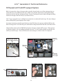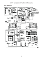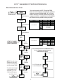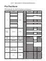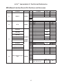
1
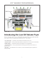
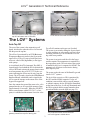
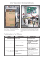
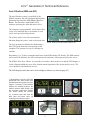
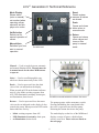
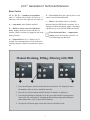
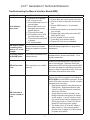
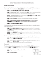
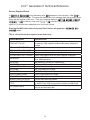
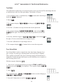
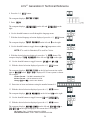
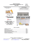
LOV™ FRYER Generation II
TECHNICAL REFERENCE MANUAL
FEB 2010
Edition
Introducing the LOV™ Fryer
1
The LOV™ Systems
2
M3000
12
RTI-equipped Systems
31
Board Replacement
38
Wiring Diagrams
41
Pin Positions
44
Frymaster and Dean Technical Service
8700 Line Ave, Shreveport, LA 71106
Service Hotline: 800-551-8633
Website: www.frymaster.com
*8196506*
LOV™ Generation II Technical Reference
M3000 Computer
Filter Light
Replace JIB Light
Diagnostic
LED Screen
JIB
(behind right door)
The LOV™ fryer.
Introducing the Low Oil Volume Fryer
The Low Oil Volume (LOV™) fryer is a McDonald’s-only, feature-laden version of the electric RE
fryer or gas H55 fryer. The enhancements found on the LOV™ fryer include:
• Low volume frypot — 30 pounds (15 liters) rather than 50 pounds (25 liters) of oil.
• Automatic top-off — the fryer automatically maintains an optimal oil level with a reservoir in the cabinet.
• M3000 computer — a sophisticated controller with multiple levels of programming.
• Automatic filtration — the fryer performs hands-free filtering at prescribed cook cycle counts or at
prescribed times.
• Oil savings — The combination of a low-volume fry vat and oil automatically kept at a optimal level,
reducing oil usage.
1
LOV™ Generation II Technical Reference
ATO Sensor
AIF Sensor
ATO Sensor
Temperature
RTD
Oil Return
Sensor
High limit
AIF Sensor
Oil Return/Top
Off Slots
High limit
Ports and sensors inside a gas frypot. Oil return/
top off is at bottom rear of cool zone.
Oil Deflector
Ports and sensors inside an electric frypot.
The LOV™ Systems
Auto Top Off
The core of the system is the automatic top-off
board, which senses when the oil level is low and
fills the pot to the top line.
Top off will continue on the next vat if needed.
The system is not suited to filling the frypot when it
is empty and there are safeguards to prevent it from
activating when the fryer is cold and the oil is resting at the lower position.
The oil level is monitored by an RTD (Resistance
Temperature Detector) sensor in the frypot at the
upper oil level. The oil is moved to the pot from a
reservoir, called a JIB (Jug In Box), to the frypot
with a pump.
The system is not active until the oil in the frypot
reaches setpoint. That temperature is monitored by
the temperature probe. The activation of the system
is handled by the fryer’s computer, the M3000. The
automatic top off system is also inactive during
filter dispose cycles.
A circuit board, the ATO (Automatic Top Off), is
located inside a box behind the JIB. It monitors the
oil-level RTD and activates the pump when it senses
an oil temperature drop of 60°F (33°C) below setpoint, indicating the oil has moved away from the
sensor. The ATO sends a signal to the MIB (Manual
Interface Board), which then sends a signal to the
AIF to open the actuator on the return valve of the
frypot to be topped off.
The system works the same in McDonald’s gas and
electric LOV™ systems.
The level of the reservoir, or JIB, is monitored by
the ATO and the M3000 computer. If a low oil
condition is not rectified with two top off attempts
or within 6 minutes, the low JIB light is illuminated
on the front of the fryer. It will stay illuminated until
the JIB is replaced and the orange button has been
pressed and held to reset the light (see page 34).
Once the actuator has opened the return valve, oil is
pumped into the vat for a specified amount of time
(approximately 60 seconds). When the ATO RTD
detects a temperature within 55°F (30°C) of setpoint, it is satisfied and the actuator closes the valve.
The ATO board positioned underneath the LON
gateway controls the top off of the fry pots.
The pump that moves oil from the reservoir to the frypots is visible above.
2
LOV™ Generation II Technical Reference
ATO Board
Transformer
The reservoir, or JIB, rests behind the right
door of the fryer. A light on the front of the fryer
illuminates when the jug is empty.
The ATO board is positioned under the LON gateway in a
box with a transformer that provides power to the board.
The LON gateway must be removed to access the ATO
board.
Troubleshooting the Top Off System
Problem
Probable Causes
Frypot tops off cold. Incorrect setpoint.
Ensure setpoint is correct.
A. J5 connection unplugged.
No power to ATO board.
B. Fuse blown.
C. Transformer malfunction.
A. Check to ensure J5 on front of
ATO board is fully locked into
connector.
B. Ensure fuse below right control
box is not blown.
C. Check that proper voltage is
present at transformer. See
charts on pages 43-47.
A. Ensure the yellow LED is
securely attached to plug J6 on
the ATO board.
B. Power in the component box is not
B. Ensure power is present in the
present.
component box.
C. If power is present in component
C. Failed transformer.
box, check the transformer for
correct voltage.
A. Loose wire connection.
The yellow JIB low light
won’t illuminate.
Corrective Action
3
LOV™ Generation II Technical Reference
Problem
Probable Causes
A. Probe temperature lower than
setpoint.
B. Oil is too cold.
C. Bad Connection.
Frypots won’t top off.
D. ATO board power loss.
E. Failed transformer/harness.
F. ATO pump failed.
G. Failed ATO board.
One vat tops off but other
vats fail to top off.
A. Loose wire connection.
B. Actuator issue.
A. Wired incorrectly.
Incorrect vat tops off.
B. Flexlines connected to wrong vat.
A. Filter error exists.
One vat doesn’t top off.
B. Actuator, pump, loose connection,
RTD or ATO issue.
4
Corrective Action
A. Check to see that fryer is heating.
Fryer temperature must be at
setpoint. Check ATO probe
resistance. If probe is bad, replace
the probe.
B. Ensure that the oil in the JIB is
above 70°F (21°C).
C. With the computer OFF, press
TEMP button and ensure the
ATO version appears. If not,
the connection between the AIF
and the ATO board may be bad.
Ensure the 6-pin CAN connectors
are tight between AIF (J4 and J5)
and ATO (J10) boards.
D. Power to the ATO board has been
cut off. Restore power to the board
and clear any service required
errors.
E. Ensure transformer in ATO box is
functioning properly. Check power
from transformer to ATO board.
Ensure all harnesses are plugged
securely into place.
F. Ensure pump is operational.
Check voltage to pump. Replace
the pump if defective.
G. Check for proper voltages using the
pin position charts found on pages
43-47. If ATO found defective,
replace ATO board and clear any
errors.
A. Ensure all wiring harnesses are
securely connected to ATO board
and solenoids.
B. Check return actuator to ensure
actuator is functional.
A. Check wiring.
B. Switch flexlines to correct vat.
A. Clear filter error properly. When
change filter pad YES/
NO is displayed, do NOT press
any button until the pan has been
removed for at least thirty seconds.
After thirty seconds have elapsed,
the computer returns to OFF or last
display.
B. Check actuator, ATO pump, wire
connections, RTD and ATO board.
LOV™ Generation II Technical Reference
Auto Filtration (MIB and AIF)
The auto filtration system is controlled by the
M3000 computer, the AIF (Automatic Intermittent
Filtration) board and the MIB (Manual Interface
Board). The filtration is made hands-off by
actuators operating the drain and return valves.
The computer is programmable, and it allows filter
cycles to be launched after a set number of cook
cycles and a prescribed elapsed time.
The system can be set to lock out automatic
filtration during busy times, such as the lunch rush.
An AIF board is mounted under each fry vat.
The fryer prompts for filtration by illuminating a
blue LED on the front and a text prompt on the
computer. The operator can say no; cooking can
continue.
Responding “yes” leads to communication between the MIB and the AIF boards. The MIB controls
and oversees the filtration; the AIF board operates the actuators, which open and close the valves.
The MIB is in the fryer cabinet. It is partially covered by a sheet metal cover and the LED display is
visible. Buttons behind the cover allow limited manual operation of the system and its valves. The
cover should be reinstalled after service.
The LED displays codes that can be used to diagnose failures (see chart on page 45).
(1) Responding to the Blue LED filter
prompt with “yes” starts a filter cycle
that lasts about as long as a cook cycle
(approx. 4 minutes). Communication
between the M3000 computer, the
manual interface (MIB board), and
the automatic intermittent filtration
(AIF board) handle the process.
(2) Actuators open and close the
drain valve and return valve, (3)
emptying and refilling the frypot.
1
2
3
5
LOV™ Generation II Technical Reference
Reset
Resets system,
ensures all valves
are closed.
Mode Display
Shows status
(auto or manual)
vat number (when
operating valves
manuals) and displays error codes.
Drain
Opens and closes
drain valves in
manual mode.
Vat Selection
Selects vat for
manual operation of
valves.
Manual/Auto
Switches fryer from
auto to manual
operation.
Return
Opens and closes
return valves and
turns on filter
pump in manual
mode.
The MIB board.
Manual — Used to toggle between automatic
and manual filtration mode. The unit must be
in manual mode for the other MIB buttons
to operate.
Select — Used to scroll through the vats,
which are shown numerically in the LED.
Drain — Used to open and close the drain
valve of the vat indicated on the display.
When pressed an LED on the button indicates
activity: slow blink, awaiting response from
AIF; LED illuminated constantly, drain open;
no illumination, drain closed.
The MIB is mounted behind the left door. See arrow.
Return — Used to open and close the return
valve on the vat indicated on the display. It also
controls the pump. When pressed an LED on the
button indicates activity:
The pump operates with a momentary switch.
Pressing and holding the return button after
the valve is open activates the filter pump.
Releasing the button deactivates the pump.
•
•
•
The mode display on the face of the MIB board
displays a range of letters, which indicate
activity or an error. These codes are listed on
the next page.
blink: awaiting response from AIF,
LED illuminated constantly: drain open,
no illumination: drain closed.
6
LOV™ Generation II Technical Reference
Error Codes
1L, 1r - 5L, 5r — Numbers correspond to
vats: “L” indicates the left side of a split vat. “r”
indicates a full vat or the right side of a split vat.
P — Pan switch: filter pan is not in place or not
sensed. Auto Filtration disabled.
r — Reset: r alternating with a vat number
indicates that the MIB board is resetting. If r is
displayed without alternating with a vat number,
a problem may exist with the MIB board itself.
A — Auto mode: auto filtration enabled.
E — Drain or return valve not in desired
state: display alternates between E and vat
number. (Ensure actuator is plugged in and in the
home position.)
Three horizontal lines — temperature
sensor: sensor did not detect that the vat
was full during auto filtration.
n — Network Error: An “n” displays for 10
seconds if no communication is received from the
cooking computer within ten seconds after a power
on.
Manual Draining, Filling, Filtering with MIB
1
3
2
1. Press the M button, which switches the board to manual. The display becomes
the number of the vat to be controlled manually.
2. Press the vat selector button until the desired vat number is displayed.
3. Press the drain button to drain the oil or the press and hold the return button to
return oil to the vat displayed. Opening the drain and pressing and holding the
return button after valve is open allows filtration.
4. Pressing the M button again returns the board to automatic mode.
7
LOV™ Generation II Technical Reference
Troubleshooting the Manual Interface Board (MIB)
Problem
Auto filtration
won’t start.
Probable Cause
Corrective Action
1. Filter pan out of position.
2. Oil Level is too low.
3. Ensure MIB board is not in
manual mode.
4. Ensure MIB cover is not
damaged and pressing
against buttons.
5. Filter relay has failed.
6. AIF disable is set to YES,
blue light doesn’t light.
7. Filter motor thermal switch
is tripped.
8. AIF clock enabled.
1. Ensure filter pan is fully inserted into fryer.
2. Ensure oil level is above the oil level sensor.
3. Ensure MIB board is in “A” automatic
mode.
4. Remove and replace cover and see if filtration will start.
5. Replace filter relay with part number 8074482 24VDC relay.
6. Set AIF disable in Level 1 to NO.
7. Press filter motor thermal switch.
8. Ensure AIF clock is set to disabled.
MIB display shows
something other
than an “A” or vat
number.
An error has occurred and
displayed character indicates
error.
No power present
at the MIB board
Transformer has failed in left
component box.
Check output on the left transformer in left
component box; should read 24VAC. If not
replace transformer.
Error remains in non-volatile
memory.
Press and hold reset button in top right corner for five seconds. The drain, return and
manual/auto LEDS will illuminate and the MIB
will reset and clear any remaining errors from
memory. Allow 60 seconds to reset. If an error
still exists, then another issue exists.
MIB will not clear
error.
See MIB display diagnostics on page 46 for
explanation.
Ensure the CAN bus system is terminated at
BOTH ENDS (on the M3000 connector J6 and
on the ATO board connector J9) with a resistor
equipped 6-pin connector.
• Unplug and reseat all wiring harnesses in
CAN system. Resistance between pins
2 and 3 on the CAN network connectors
should be 120 ohms.
• Check software version numbers on all
M3000 computers and ensure all display
an AIF version. If an AIF version is missing, the AIF board may be missing power.
Check pins 5 and on J4 and J5 of the affected AIF board for proper voltage.
• The locator pin in J2 of the AIF board is
either loose or in the incorrect position.
See the chart on pages 47 of this manual
for proper pin position.
MIB indicates incorrect number of
vats.
8
LOV™ Generation II Technical Reference
Problem
Probable Cause
Corrective Action
MIB board alternatNetwork error on the CAN bus
ing “E” and “vat
communication.
number and side.”
9
A. Ensure the CAN bus system is terminated
at BOTH ENDS (on the M3000 connector
J6 and on the ATO board connector J10)
with a resistor equipped 6-pin connector.
B. With the computer OFF, press TEMP button and ensure the AIF version appears.
If not, the 24V to the AIF boards may be
missing. Ensure all 6-pin CAN connectors
are tight between the M3000 (J6 and J7),
MIB (J1 and J2), AIF (J4 and J5) and ATO
(J10) boards.
C. With the computer OFF, press TEMP button and ensure the ATO version appears. If
not, check the CAN wire harness between
the AIF board J4 or J5 and the ATO board
J9 or J10. The ATO fuse on the right side
of the ATO box may be loose or blown;
the 110V to the ATO transformer may be
missing or bad. The J4/J5 connector may
be loose.
D. Check to see if MIB has 24V on pins 5 and
6 of J2. Check to see if 24V is present on
pins 5 and 6 of wire harness plugging into
J4 or J5 of the first AIF board. If 24V missing, check the pins. Replace the harness if
necessary.
E. Check continuity between each color wire
on the CAN connectors into J7 on the far
right computer and J10 on back of the ATO
board (black to black, white to white, and
red to red) and ensure there is no continuity between different color wires (black to
red, red to white, and white to black).
F. Ensure black computer locator wires are
connected from ground to correct pin position (see pages 43-47).
G. Ensure all boards have the corner ground
wire attached and tightened.
H. Check for loose locator pin or incorrect
positioning in J2 of the AIF board. See the
charts on pages 43-47 of this manual for
proper pin position.
I. Bad MIB and/or AIF board.
J. Broken resistor lead. Unwrap the resistor
leads and check ends.
LOV™ Generation II Technical Reference
Troubleshooting the AIF System (AIF)
Problem
Wrong vat
opens.
Actuator doesn’t
function.
Probable Cause
Fix
1. Actuator is plugged into wrong
connector.
2. Locator pin is in wrong position.
1. Ensure the actuator is plugged into the correct
connection (J1 for FV return, J3 for DV return;
J6 for FV drain, J7 for DV drain).
2. Ensure the locator pin is in the proper position
in plug J2. (See charts on pages 43-47 of this
manual for proper pin position.)
1. Check pins 5 and 6 of J2 at the MIB board.
Should read 24VDC. Check voltage on pins
5 and 6 at the other end of the harness and
ensure 24VDC is present. Check pins 5 and 6
for 24VDC on plugs J4 and J5 on AIF boards.
2. Ensure actuator leads are plugged into AIF
board (J1 for FV return, J3 for DV return; J6
for FV drain, J7 for DV drain).
3. Check the power on the connector of the
problem actuator while manually opening
or closing the actuator. Pins 1 (black) and 4
(white) should produce +24VDC when the
actuator is opening; -24VDC should be read
from Pins 2 (red) and 4 (white) when the
actuator is closing. If either voltage is missing,
the AIF board is likely bad. Test the actuator
by plugging into another connector to open
or close. If the actuator operates, replace the
board.
4. Check resistance of the potentiometer
between pin 2 (purple wire) and pin 4 (gray/
white wire). Closed should read 0-560Ω. Open
should read 3.8KΩ - 6.6KΩ.
5. If proper voltages are seen at the connector
and the actuator doesn’t operate, replace the
actuator.
1.
2.
3.
4.
No power to AIF board.
Actuator unplugged.
AIF board failure.
Actuator readings are out of
tolerance.
5. Actuator is bad.
Oil Return Sensor Troubleshooting (Gas LOV™ Fryers)
The oil return sensor is a device that is used
to prevent dry firing of the burners. The
sensor looks similar to a high limit. The
sensors are energized when the computer
is powered on with a soft on. The sensor
heats up and detects the oil around it.
During filtration when the oil is drained, it
senses the difference between the oil and
air. It is controlled with a board located
next to the interface board (right) and a
separate egg shaped plastic device (far
right) that contains additional electronics.
Use care when working with the sensor as
temperatures may reach as high as 500°F
(260°C).
The oil return sensor is controlled by a small green board
and the electronics inside the plastic, egg-shaped device
shown above to prevent dry firing.
10
LOV™ Generation II Technical Reference
If oil is surrounding the heater, the oil will prevent the heater from ever reaching its setpoint. Once
oil is removed during filtration, the heater reaches setpoint and cycles a thermostat every four
seconds. Since the cycle is only four seconds long, the seven second delay is not made and the gas
valve won’t open.
The 120VAC is on T2 in the control box traveling in on pin 11 of J3 and out pin 7 on J1 (DV) or pin
7 on J3 (FV).
Typical sensor-related failures:
• Low temp but no call for heat (heat light),
• Stuck in melt cycle with no call for heat,
• Filter error (IS
IS VAT FULL?
FULL?) with oil in the filter pan (no oil in the vat).
If the computer doesn’t exit melt cycle or continues to display low temp and does not heat,
ensure that the gas supply, gas valve, and other components are working properly. If no heat lamp
illuminates because no call for heat is initiated, check the following (see diagram below):
• Power to oil sensor (from previous basket lift relay on interface board K1(DV) or K4 (FV)). Check
pin 7 on J1 (DV) or pin 7 on J3 (FV) for 120VAC.
• Power to heater/relay coil on relay board. Check voltage to the coil on pins 8 and 1 to ensure that
120VAC is present with oil in the vat. If the vat is empty, the power will cycle 4 seconds on, 4
seconds off.
• Check between pin 3 and 2; 5VDC for air and 0VDC for oil. A common message for a shorted
harness or issue is IS DRAIN CLEAR? with oil in the filter pan.
• Check ground on pin 2 on relay board to stud for a secure ground.
• Check AIF communication harness. Interrupted communication will prevent the fryer from
heating.
• If the oil level sensor is cycling 4 sec. on/off and oil is surrounding the sensor, the sensor may have
a carbon build up that is self insulating the sensor. Use a no scratch pad to remove carbon build up.
Black
(To J1 Pin 7 (DV)
or J3 Pin 7 (FV))
120V
White
(To T2 Terminal Block
Line Voltage In From
Oil Level Sensor
(Basket Lift) Relay on
Interface Board
Thermocouple
Fixed Setpoint
Temp. Control
24VAC from Interface Board
through High Limit (Ign. Module
Call for Heat)
To (optional Drain
Switch) and Gas
Valve
Heater
(350 ohms US)
(1325 ohms Intl)
120V
120V (US) 230V (Intl) 40W
Heater w/ Thermocouple
1
Black 8
Black
7
C
Black 6
NO
5
NC
White
2 Green
3
Red
4
Time Delay Relay Board
DPDT 7sec. Delay on Make
11
To AIF Board J2 Pin 9 DV
or 10 FV (AIF Oil Signal)
LOV™ Generation II Technical Reference
M3000 Computer
Overview
Filter, Temp, Info, Programming
and Navigation Buttons
Cook Cycle and
Selection Buttons
LED Display
ON/OFF
Heat Indicator
Lamp
LED Display
Product Buttons
ON/OFF
The M3000 computer retains the one-button ease of the M2000 and M100B, combining it with the
utility of 40-product menu capability. It will operate with electric and gas fryers, both full- and splitvat.
On single product vats, press any of the cook cycle buttons to begin cooking. On multi-product vats,
press a product button, and then a cook cycle button under the display showing the desired product
name.
For example, a typical M3000 computer on a 3-vat fry station will display FR FRIES.
FRIES Pressing
one of the cook cycle buttons will begin a cook cycle for French fries.
The chicken/fillet station will usually display dashed lines [-------]. Pressing the product button
assigned to McChicken, for example, will cause mcchick to be displayed. Then, press a cook
cycle button beneath the word mcchick to start a cook cycle for McChicken.
MCC HICK
---- ----
---- ----
Product Buttons
MCC HICK
Cook Cycle Buttons
12
LOV™ Generation II Technical Reference
Navigation
The M3000 uses
and
buttons to navigate the various menus and submenus.
When programming, the left screen shows the menu or submenu item. The right screen is for data
entry. Data is entered with alpha-numeric characters, scrolling through lists or by toggling between
choices (see diagrams on previous page).
During programming, if a button is not pushed within one minute, the computer returns to operation
mode.
Cook Cycle and Selection Buttons
The 9 and 8 buttons are dual-function buttons shared with the number 1 and 2 buttons. They are
located directly below the LED displays (see diagrams on previous page). Use these buttons to select
or cancel functions. The 8 button is used to back out of and quit submenus.
Filter, Temperature, and Info Buttons
The < FLTR and FLTR > buttons (see diagram) are used to filter the left and right vats of a split vat
fryer on demand, while the right FLTR > button is used to filter a full vat on demand. If pressed once,
the FLTR buttons will display the number of cook cycles remaining until a filtration prompt. When a
FLTR button is pressed twice, the date and time of the last filter will be displayed.
Temp Button
The TEMP button, if pressed once while the fryer is on, displays current vat temperature on both
sides. If the TEMP button is pressed twice while the fryer is on, it shows the setpoint temperatures of
the vats. If the fryer is off, the display shows the current versions of software.
Info Button
The INFO button, if pressed once when the fryer is on, shows the recovery time for each vat from the
last test. Recovery displays the time required for the fryer to raise the temperature of the oil 50°F
(28°C) between 250°F (121°C) and 300°F (149°C). Maximum recovery time should not exceed 1:40
for electric or 2:25 for gas.
If recovery time exceeds these times, the computer will display RECOVERY FAULT.
FAULT The error
can be cleared and alarm silenced by pressing the 9 button. The second consecutive time it will
display RECOVERY FAULT CALL SERVICE
SERVICE. The error can be silenced and temporarily
cleared by pressing the 9 button. However, each time the fryer is started up and the test performed,
the error will continue to appear until code 0042 is entered in tech mode (see page 27).
If the INFO button is pressed and held for three seconds it shows information such as usage, filter
statistics and last cook cycles.
13
LOV™ Generation II Technical Reference
Basic Operation
Cook Channel
and Selection Buttons
Filter, Temp, Info,
Programming and Navigation Buttons
ON/OFF
Product Buttons
Start Two-Button Cook Cycle (Multi-Product Mode)
Press product key
bearing icon for desired
2
product. Press cook
channel button to begin
cook cycle.
Turn Fryer ON
Press right key for full
pot; press key on desired
side on a split pot.
Turn Fryer OFF
Press right key for full
pot; press key on desired
side on a split pot.
Check Frypot Temperature
Press Temp key once.
Displays show frypot
temperatures.
Check Frypot Setpoint
Press Temp key twice.
Displays show frypot
setpoint temperatures.
TEMP
Change From Dedicated to Multi-Product Mode
Press and hold Cook
Channel button under
2
displayed menu item for
approximately 3 seconds
until beep is heard.
Display changes to dashed
lines.
TEMP
Change From Multi-Product Mode to Dedicated Mode
Cancel Duty or Remove Alarm
Press key under active
2
display.
Start One-Button Cook Cycle
(Dedicated Mode)
Press key under
display showing
desired item.
ON/OFF
Press product key bearing
icon for desired product.
Press cook channel button
under display showing
desired item until beep is
heard (approx 3 seconds).
1
14
2
LOV™ Generation II Technical Reference
Cooking With Multi-Product Display
1
Dashed lines appear
in both displays.
2
Press a product
button.
3
Vat with appropriate
setpoint displays:
MC CHICK. Skip
to step 5.
4
Vat with inappropriate
setpoint displays:
If this occurs, change
setpoint by pressing the
button assigned to the
product. When the
chevrons appear,
immediately press and
hold the cook button
until a beep is heard
(approximately three
seconds) and then
release it.
5
Press a cook channel
button to begin cook
cycle.
-------McC
K
Display alternates
between MCCK and
remaining cook time.
7
If a duty is required for
this menu item, duty is
displayed when it is time
to perform a duty, such
as shake.
8
Press cook
channel button
under duty display
to cancel alarm.
9
Pull is displayed
when the cook time
is complete; an
alarm sounds.
Mc chick
<<<<>>>>
McC
K
<<<<>>>>
10
Press cook
channel button
under pull display
to cancel alarm.
11
Dashed lines reappear
under active display at
the end of the cook
cycle.
1
1
NOTE: If error Remove Discard Product
appears, press the cook channel button
under the message to cancel alarm and
remove error message.
15
Mc cK
6
2:34
duty
2
pull
2
-------
LOV™ Generation II Technical Reference
Cooking With Dedicated Display
Fr fries
1
A menu item, such as
FR FRIES shows in
display
2
Press a cook channel
button to begin the
cook cycle.
3
Display alternates
between abbreviated
product name and
remaining cook time.
fr fries
8
Q7 is displayed and
alternates with
FRY. As the quality
time counts down.
1
9
Pressing the cook
channel button now
will launch a cook
cycle and end the
quality countdown.
FRY
2:34
4
Duty is displayed
when itis time to shake
the fry .basket
duty
5
Press cook channel
button to cancel alarm.
1
6
Pull is displayed
when the cook cycle
is complete.
pull
7
Press cook channel
button to cancel
alarm.
1
10
QUAL is displayed
when the quality
time has elapsed.
11
Pressing the cook
channel button
restores the display
to FR FRIES and the
.
unit is ready for
cooking
16
Q7
Q1
Fry
Fry
1
Qual
1
FR
FRies
LOV™ Generation II Technical Reference
Changing from Breakfast Setup to Lunch
Hash brn
2
Computer will change
from Hash Brn to
<<<<<>>>>>; an
alarm will sound.
3
RY
Press and quickly
release product
button for french fries.
FF
1
Hash brn
hash brn
<<<<<>>>>>
4
Press and hold the cook
channel button under the
display until a beep is
heard (approximately three
seconds) and release.
Display changes to FR
Fries.
.
1
fr fries
Perform these steps on both sides to change both displays to FR FRIES.
17
LOV™ Generation II Technical Reference
Changing from Lunch Setup to Breakfast
Fr fries
Computer displays
FR FRIES.
2
Press and quickly
release product
button for hash
browns.
3
Computer display
will change from
FR Fries to
<<<<<>>>>>; an
alarm sounds.
FR FRies
H
br ash
n
1
fr fries
Fr fries
4
Press and hold the cook
channel button under the
display until a beep is
heard (approximately
three seconds) and release.
5
Display changes to
Low Temp until
setpoint is reached.
LOW temp
6
Display changes to
Hash Brn.
hash brn
<<<<<>>>>>
Perform these steps on both sides to change both displays to FR FRIES.
18
1
LOV™ Generation II Technical Reference
The following chart maps the menu options available in the M3000 computer and indicates the
location of more information on each menu item within the LOV™ Fryer Installation and Operation
Manual. For more information, consult the indicated section.
Location in IO manual
M3000 Menu Items
Adding New Menu Items
Storing Menu Items in Product Buttons
Draining, Refilling, and Disposing of Oil
See section 4.10.2
See section 4.10.3
See section 4.10.4
Filter Menu ………………………………………………………………………………………………………….. 4.11
[Press and hold ◄ FLTR or FLTR ►]
Auto Filter
Maint Filter
Dispose
Drain to Pan
Fill Vat from Drain Pan
Fill Vat from Bulk (Bulk Only)
Pan to Waste (Bulk Only)
Programming
Level 1 Program…….……………….....………………………………………………………….. 4.12
[Press and hold TEMP and INFO buttons, 2 beeps, displays Level 1, enter 1234]
Product Selection ..…….....………………………………………………………….. 4.10.2
Name
Cook Time
Temp
Cook ID
Duty Time 1
Duty Time 2
Qual Tmr
AIF Disable
Assign Btn
AIF Clock ..………………………………………………………………………………… 4.12.1
Disabled
Enabled
Deep Clean Mode ……..……………………...…………………………………….. 4.12.2
High-Limit Test …………….…………………….…………………………………….. 4.12.3
Fryer Setup …………………….……………………………………………………………….. 4.9
Level 2 Program (Manager Level) ……………………………………………….. 4.13
[Press and hold TEMP and INFO buttons, 3 beeps, displays Level 2, enter 1234]
Prod Comp Sensitivity for product …………………………………….. 4.13.1
E-Log
Log of last 10 error codes …………………………….. 4.13.2
Password Setup Change passwords ……………………………… 4.13.3
Setup [enter 1234]
Usage [enter 4321]
Level 1 [enter 1234]
Level 2 [enter 1234]
Alert Tone Volume and Tone ...………………………………………….. 4.13.4
Volume 1-9
Tone 1-3
Filter After Sets number of cooks before filter prompt ………….. 4.13.5
Filter Time Sets amount of time between filter cycles ………….. 4.13.6
Tech Mode
[Press and hold ◄ and ► for 10 seconds, 3 beeps, displays TECH MODE, enter
1650]
Clear Passwords
Filter Pad Time
Info Mode ………………...………………………...………………………………………..……………………….. 4.14
[Press and hold INFO for 3 seconds, displays Info Mode]
Full/Split Vat Configuration
Filter Stats ..……………….……………………………………………………………….. 4.14.1
Review Usage ………….……………………………………………………………….. 4.14.2
Last Load ………………….……………………………………………………………….. 4.14.3
19
LOV™ Generation II Technical Reference
Loading and Updating Software Procedures
Updating the software takes approximately 20 minutes. To update the software, follow these steps:
1.
Switch all computers to OFF
OFF. Press the TEMP button to check current M3000/MIB/AIF/ATO software
version.
2.
Remove the two screws on the left side cover plate of the M3000 board.
3.
With the computer folded down, insert the SD card into the slot on the left side of the M3000. The
contacts on the card should face down and the notch should appear on the bottom right (see pictures
below).
4.
Once inserted, UPGRADE IN PROGRESS appears on the left display and WAIT on the right.
5.
The display then changes to CC UPDATING on the left and the percentage completed appears on the
right. The display counts up to 100 on the right, changing to a flashing BOOT
BOOT. DO NOT REMOVE
THE CARD UNTIL THE DISPLAY PROMPTS TO DO SO IN STEP 8.
6.
Then, UPGRADE IN PROGRESS is displayed on the left display and WAIT on the right again,
followed by COOK HEX
HEX, mib HEX
HEX, aif HEX ending with aTO HEX displayed on the left and
the percentage complete on the right.
7.
The display then changes to REMOVED SD CARD on the left and 100 on the right.
8.
Remove the SD card using the fingernail slot on the top of the SD card.
9.
Once the SD card is removed the display changes to CYCLE POWER
POWER.
10. Cycle the control power using the hidden reset switch behind the right control box (see page 38). HOLD
THE SWITCH FOR 10 SECONDS ENSURING THE MIB BOARD HAS POWERED FULLY
DOWN.
11. M3000 CAN TX FULL (a SERVICE REQUIRED error) may appear while computers are
rebooting. Press YES at the prompt to cancel alarm. A flashing BOOT is displayed on the remaining
computers while the program is transferred.
12. When the update is complete, the M3000 displays OFF
OFF. The MIB display will remain blank while
software is loading, changing to show the vat numbers. Once the LEDs stop blinking, press YES to
SYSTEM ERROR FIXED? Enter 1111. The MIB board will display A.
13. Cycle the control power using the hidden reset switch behind the right control box again. ENSURE
THE SWITCH IS HELD FOR 10 SECONDS. WAIT ANOTHER 20 SECONDS UNTIL THE MIB
BOARD HAS FULLY RESET BEFORE CONTINUING.
14. With the computer displaying OFF
OFF, VERIFY software update by pressing the TEMP button to check
updated M3000/MIB/AIF/ATO version on each computer. IF ANY BOARDS DID NOT UPDATE,
REPEAT THE PROCESS STARTING WITH STEP 3.
Remove the SD card
using the fingernail
slot on the top of the
card.
Insert the SD card
with contacts facing down.
20
LOV™ Generation II Technical Reference
M3000 Troubleshooting
Problem
Probable Causes
A. Computer not turned on.
B. No power to the fryer.
C. Power switch turned off.
D. Loose fuse holder.
No display on computer.
E. Computer has failed.
F. Damaged computer wiring
harness.
G. Power supply component or
interface board has failed.
Computer locks up.
A. Press the ON/OFF switch to turn
the computer on.
B. This fryer may have two cords: a
computer power cord and a main
power cord. If the computer cord
is not plugged in, the computer will
not activate. Verify computer power
cord is plugged in and that circuit
breaker is not tripped.
C. Some fryers have a rocker power
switch inside the cabinet below the
computer. Ensure the switch is
turned on.
D. Ensure fuse holder is screwed in
properly.
E. Swap the computer with a computer
known to be good. If computer
functions, replace the computer.
F. Swap with a harness known to
be good. If computer functions,
replace the harness.
G. If any component in the power
supply system (including the
transformer and interface board)
fail, power will not be supplied to
the computer and it will not function.
Remove and restore power to the
computer.
Computer error.
A. Another filtration cycle is still in
process.
M3000 display shows
filter busy
busy.
Corrective Action
B. Computer error.
C. Computer error.
21
A. Wait until the previous filtration
cycle ends to start another filtration
cycle.
B. A computer has an error. Using
the filter menu, try to perform
a FILL VAT FROM DRAIN
PAN on each vat (see Chapter 4
of the BIELA14 IO manual). Only
computers with errors can perform
this function with a filter busy error.
Computer should clear and return
to normal operation once complete.
C. If filter busy is still displayed with
no activity, ensure the filter pan is
empty and remove and restore ALL
power to the fryer.
LOV™ Generation II Technical Reference
Problem
Probable Causes
Corrective Action
Recovery time exceeded maximum
time limit for two or more cycles.
Silence the alarm by pressing the 9
button. Clear the error using the code
on page 25. Maximum recovery for
electric is 1:40.
Wrong energy type selected in
setup.
Press 1234 to enter setup and set
energy type for electric.
An error has occurred.
Press 1234 to enter setup and
reconfigure the computer.
An error has occurred.
Press YES to silence alarm. The
error is displayed three times. See
list of issues on page 26. Fix issue.
The computer displays SYSTEM
ERROR FIXED? YES/NO. Press
YES. Computer displays ENTER
CODE.. Enter 1111 to clear error
CODE
code. Pressing NO will allow the fryer
to cook, but error will be redisplayed
every 15 minutes.
Incorrect display option
programmed.
See page 28 to change temperature
scale.
Filter error has occurred, filter pad
clogged, 24 hour filter pad change
prompt has occurred, or change
filter pad was ignored on a prior
prompt.
Change the filter pad and ensure the
filter pan has been removed from the
fryer for a minimum of 30 seconds.
Do NOT ignore CHANGE FILTER
PAD prompts.
M3000 display shows
INSERT pan
pan.
A. Filter pan is not fully inserted into
fryer.
B. Missing filter pan magnet.
C. Defective filter pan switch.
A. Pull filter pan out and fully reinsert
into fryer.
B. Ensure the filter pan magnet is in
place and replace if missing.
C. If the filter pan magnet is fully
against the switch and computer
continues to display INSERT
pan, switch is possibly defective.
pan
M3000 display shows
hot-hi-1.
hot-hi-1
Frypot temperature is more than
410ºF (210ºC) or, in CE countries,
395ºF (202ºC).
This in an indication of a malfunction
in the temperature control circuitry,
including a failure of the high-limit
thermostat.
Computer in high-limit test mode.
This is displayed only during a test of
the high-limit circuit and indicates that
the high-limit has opened properly.
M3000 display shows
RECOVERY FAULT
CALL SERVICE.
M3000 display
shows ENERGY
MISCONFIGURED
M3000 display shows
EXCEPTION ERROR
with the description on the
right.
M3000 displays SERVICE
REQUIRED followed by
the error.
M3000 display is in
wrong temperature scale
(Fahrenheit or Celsius).
M3000 displays CHANGE
FILTER PAD
PAD.
M3000 display shows HILIMIT.
LIMIT
22
LOV™ Generation II Technical Reference
Problem
M3000 display shows
low temp alternating
with MLT-CYCL
MLT-CYCL.
M3000 display shows
ERROR RM SDCRD
M3000 display shows
TEMP PROBE
FAILURE.
MAINT FILTER (Manual
Filter) won’t start.
Probable Causes
Corrective Action
Frypot temperature is between
180°F (82°C) and 315°F (157°C).
This display is normal when the fryer
is first turned on while in the melt cycle
mode. To bypass the melt cycle press
and hold either #1 or #2 product button
under the LCD display until a chirp is
heard. The computer displays EXIT
MELT alternating with YES and NO
NO.
Press the #1 YES button to exit melt.
If the display continues, the fryer is not
heating.
Defective SD card.
Replace card with another card.
A. Problem with the temperature
measuring circuitry including the
probe.
B. Damaged computer wiring
harness or connector.
A. This indicates a problem within the
temperature measuring circuitry.
Check resistance of probe, if faulty
replace probe.
B. Swap the computer wiring harness
with one known to be good. If
problem is corrected, replace the
harness.
Ensure fryer is at setpoint before starting
MAINT FILTER.
Temperature too low.
M3000 display shows
REMOVE DISCARD
DISCARD.
Remove and discard product. Press a
In non-dedicated mode, a product is cook button under the display with the
dropped that has a different setpoint error to remove the error. Reset the
that the current vat temperature.
setpoint of the vat before trying to cook
product.
M3000 display shows
HEATING FAILURE.
FAILURE
Failed computer, failed interface
board, open high-limit thermostat.
Turn off the vat with the problem. This
error is displayed if the fryer loses its
ability to heat oil. It is also displayed
when the oil temperature is above
450°F (232°C) and the high-limit
thermostat has opened, halting the
heating of the oil.
Failed computer.
Replace computer
Computer in high-limit test mode.
This is displayed during a test of the
high-limit circuit to indicate if the highlimit has failed.
Failed high-limit.
This is displayed to indicate the highlimit has failed.
Computer will not go into
program mode or some
buttons do not actuate.
M3000 display shows HI
2 BAD.
M3000 display shows
HELP HI-2 or HIGH
LIMIT FAILURE
FAILURE.
23
LOV™ Generation II Technical Reference
Problem
M3000 display shows
software for only M3000
or MIB but not all boards.
M3000 display shows
low temp
temp, heating
indicator cycles on and
off normally but fryer
does not heat.
M3000 display shows IS
VAT FULL? YES NO.
Fryer filters after each
cook cycle.
Probable Causes
Corrective Action
Loose or damaged harness.
Check that all harnesses between
M3000’s, MIB, AIF and ATO are
secure. Ensure 24VDC is present on
pins 5 & 6 of J2 on MIB board and on
J4 or J5 of AIF board. Check for loose
or broken pins/wires. If the problem
persists, swap out computer from one
bank to another and cycle power on
the fryer.
A. Three phase power cord
unplugged or circuit breaker is
tripped.
B. Failed computer.
C. Damaged computer wiring
harness.
D. Open connection in high-limit
circuit.
A. Ensure all cords are fully seated in
the receptacles, locked into place
and that circuit breakers are not
tripped.
B. Replace computer.
C. Replace computer wiring harness.
D. Check high limit circuit starting at
the control box connector working
to the high-limit.
A filter error has occurred due to
dirty or clogged filter pad or paper,
clogged filter pump, filter pump
Follow the steps in the flowchart on
thermal overload, improperly
page 30.
installed filter pan components, worn
or missing O-rings, cold oil or an
actuator problem.
Filter after setting incorrect or
software update issue.
24
Overwrite the filter after setting by reentering the filter after value in level two.
Ensure that the down arrow is pressed
after entering the value to save the
setting (see Chapter 4 in the BIELA14
IO Manual for more information).
LOV™ Generation II Technical Reference
M3000 Useful Codes
To enter any of the following codes: Press and hold and simultaneously for TEN seconds; three
chirps sounds. The computer displays TECH MODE
MODE. Enter the codes below to perform this function.
• 0042 – Reset RECOVERY FAULT CALL SERVICE
SERVICE.
off. Turn the computer on and check
• 1658 – Change from F° to C°. The computer displays off
temperature to see the temperature scale. If the desired scale is not displayed, repeat.
• 3322 – Reset Factory Menu. The computer displays COMPLETE
COMPLETE, and then off
off. (NOTE:
This will delete any hand-entered menu items.)
• 1650 – Enter Tech Mode. See page 1-36 to reset passwords and change filter pad time.
• 1212 – Switch Between Domestic and International Menu. The computer displays
COMPLETE, and then off
COMPLETE
off. (NOTE: This will delete any hand-entered menu items.)
• 0469 – Reset Filter Stat Data
Data.
The following codes require the removal and reinsertion of the J3 locator plug on the rear of the computer
before entering the code.
• 1000 – Reset CALL TECH Message. Disconnect board locator plug (J10). Reinsert plug.
Enter 1000
1000. Computer display switches to off
off. Remove and then restore power to the computer
using the 20-pin plug.
• 9988 – Reset BADCRC Message. Disconnect board locator plug (J10). Reinsert plug. Enter
9988. Computer display switches to off
9988
off. Remove and then restore power to the computer using
the 20-pin plug. Replace the computer.
The following codes are entered when prompted to do so or from an energy misconfigured exception error.
• 1111 – Reset SERVICE REQUIRED Message. Enter this when the issue is fixed and you
are prompted to enter.
• 1234 – Enter SETUP MODE from energy misconfigured exception error. (This usually can be done without pressing the filter buttons if an error is displayed.)
Passwords
To enter level one, level two passwords – Press and hold the TEMP and INFO buttons simultaneously until level 1 or level 2 is displayed. Release the buttons and ENTER Code appears.
• 1234 – Fryer Setup, Level One, and Level Two.
• 4321 – Usage Password.
25
LOV™ Generation II Technical Reference
Service Required Errors
A SERVICE REQUIRED error alternating with YES displays on the computer. After YES is
pressed the alarm is silenced. The computer displays an error message from the list below three
times with the location of the error. Then, the computer displays SYSTEM ERROR FIXED?
YES/NO. If yes is chosen, enter code 1111
YES/NO
1111. If NO is chosen, the system returns to cook
mode for 15 minutes then redisplays error until issue is fixed.
Pressing the MIB reset button during any filter function will generate a SERVICE REQUIRED error.
This is a list of the service required errors and cause.
ERROR MESSAGE
PUMP NOT FILLING
DRAIN VALVE NOT OPEN
DRAIN VALVE NOT CLOSED
RETURN VALVE NOT OPEN
RETURN VALVE NOT CLOSED
MIB BOARD
AIF BOARD
ATO BOARD
HIGH LIMIT FAILURE
AIF PROBE
ATO PROBE
TEMP PROBE FAILURE
MIB SOFTWARE
INVALID CODE LOCATION
MISCONFIGURED ENERGY
TYPE
RTC INVALID DATE
EXPLANATION
Oil not returning to vat quickly. Possible problems: dirty pad, bad
or missing O-rings, tripped or defective filter pump, actuators or
linkage.
Drain valve failed to open; the valve’s position is unknown.
Drain valve failed to close; the valve’s position is unknown.
Return valve failed to open; the valve’s position is unknown.
Return valve failed to close; the valve’s position is unknown.
Problem with CAN communications; check for loose CAN connections. MIB board failure.
MIB detects AIF missing; AIF board failure.
MIB detects ATO board connection lost; ATO board failure.
High limit circuit has an issue.
AIF RTD reading out of range.
ATO RTD reading out of range.
TEMP Probe reading out of range.
Internal MIB software error.
SD card removed during update.
Energy type in fryer setup is incorrect; set proper energy type gas
or electric. Press 1234 to enter setup to properly configure fryer.
The date is invalid. Press 1234 to enter setup to properly configure fryer and set proper date.
26
LOV™ Generation II Technical Reference
CODE
ERROR MESSAGE
EXPLANATION
E01
REMOVE DISCARD (Right)
A product cook is started on the right side of a split vat
or in a full vat that has a different setpoint other than the
current vat temperature.
E02
REMOVE DISCARD (Left)
A product cook is started on the right side of a split vat
or in a full vat that has a different setpoint other than the
current vat temperature.
E03
ERROR TEMP PROBE FAILURE
TEMP Probe reading out of range.
E04
HI 2 BAD
High limit reading is out of range.
E05
HOT HI 1
High limit temperature is past more than 410°F (210°C),
or in CE countries, 395°F (202°C).
E06
HEATING FAILURE
A component has failed in the high limit circuit such as
computer, interface board, contactor or open-high limit.
E07
ERROR MIB SOFTWARE
Internal MIB software error.
E08
ERROR ATO BOARD
MIB detects ATO board connection lost; ATO board
failure.
E09
ERROR PUMP NOT FILLING
Oil not returning to vat quickly. Possible problems: dirty
pad, bad or missing O-rings, tripped or defective filter
pump, actuators or linkage.
E10
ERROR DRAIN VALVE NOT OPEN
Drain valve failed to open; the valve’s position is
unknown.
E11
ERROR DRAIN VALVE NOT CLOSED
Drain valve failed to close; the valve’s position is
unknown.
E12
ERROR RETURN VALVE NOT OPEN
Return valve failed to open; the valve’s position is
unknown.
E13
ERROR RETURN VALVE NOT CLOSED
Return valve failed to close; the valve’s position is
unknown.
E14
ERROR AIF BOARD
MIB detects AIF missing; AIF board failure.
E15
ERROR MIB BOARD
Cooking computer detects MIB connections lost;
check software version on each computer. If versions
are missing, check CAN connections between each
computer; MIB board failure.
E16
ERROR AIF PROBE
AIF RTD reading out of range.
E17
ERROR ATO PROBE
ATO RTD reading out of range.
E18
Not Used
E19
M3000 CAN TX FULL
Connection between computers lost.
E20
INVALID CODE LOCATION
SD card removed during update.
E21
FILTER PAD PROCEDURE ERROR
(Change Filter Pad)
25 hour timer has expired or dirty filter logic has
activated.
E22
OIL IN PAN ERROR
The MIB has detected oil may be in the pan.
E23
CLOGGED DRAIN (Gas)
Vat did not empty during filtration.
E24
OIL RETURN (level) SENSOR FAILED
(Gas)
Oil return sensor may have failed.
E25
RECOVERY FAULT
Recovery time exceeded maximum time limit.
E26
RECOVERY FAULT CALL SERVICE
Recovery time exceeded maximum time limit for two or
more cycles.
E27
LOW TEMP ALARM
Oil temperature has dropped lower than 15°F (8°C) in
idle mode or 45°F (25°C) in cook mode.
27
LOV™ Generation II Technical Reference
Tech Mode
Tech mode allows technicians to reset all passwords set in Levels One and Two and change the time
at which the fryer calls for a filter pad change. The default is 25 hours.
1. Press and hold and simultaneously for TEN seconds until a third chirp is
heard and CODE is displayed.
2. Enter 1650
1650.
3. The computer displays TECH MODE and changes to CLEAR PASSWORDS.
WORDS
4. Press the 9 (1) button to accept selection and clear the passwords.
5. The computer displays CLEAR PASSWORDS on the left and COMPLETE on the right. This clears any passwords set up under levels one and
two.
6. Press the button to toggle to FILTER PAD TIME on the left and 25 on
the right. (25 hours is the default time to change the pad.)
7. Press the 8 (2) button to accept changes and exit.
OFF. Continue below to enter the setup mode.
8. The computer displays OFF
Fryer Setup Mode
Fryer Setup Mode is used to setup the time, date, date format, language, fryer
type, vat type, oil system type, and temperature scale in the fryer’s computer.
These settings are needed for the fryer to function properly and should only be
changed by a technician upon initial power up after installing a new computer or
after accessing from Level 1.
With the computer displaying OFF
OFF:
1. Enter Level 1 programming mode by pressing the TEMP and INFO buttons
simultaneously until LEVEL 1 is displayed. The computer displays ENTER
CODE.
CODE
1234.
2. Enter 1234
The computer displays level 1 program for three seconds changing to
Product selection .
3. Press the a button once to scroll to FRYER SETUP.
SETUP
28
LOV™ Generation II Technical Reference
yes) button.
4. Press the 9 (1 yes
CODE.
The computer displays ENTER CODE
5. Enter 1234
1234.
The computer displays Language on the left and english on the
right.
6. Use the _ and ` buttons to scroll through the language menu.
7. With the desired language selection displayed, press the 9 (1 yes
yes) button.
The computer displays temp format on the left and f on the right.
8. Use the _ and ` buttons to toggle between f and c temperature scales.
NOTE: F is used for Fahrenheit, C is used for Celsius.
yes) button. The
9. With the desired selection displayed, press the 9 (1 yes
computer displays time format on the left and 12 hr on the right.
hr.
10. Use the _ and ` buttons to toggle between 12 hr and 24 hr
11. With the desired selection displayed, press the 9 (1 yes
yes) button .
The computer displays enter time on the left and current time on the
right in hh:MM format. AM or PM is displayed if 12 hour system is chosen.
For example:
12 Hour Format – 7:30 AM is entered as 0730.
24 Hour Format – 2:30 is entered as 1430.
Change AM and PM – use the cd buttons.
12. Enter time in hours and minutes using the number buttons 0-9.
13. With the desired selection displayed, press the 9 (1 yes
yes) button.
The computer displays DATE FORMAT on the left and US on the right.
14. Use the _ and ` buttons to toggle between US and interntl
interntl.
15. With the desired selection displayed, press the 9 (1 yes
yes) button.
The computer displays enter date on the left and MM-DD-YY or
DD-MM-YY on the right changing to the current date. For example:
US Format – Dec. 5, 2008 is entered as 120508.
International Format – 5 Dec. 2008 is entered as 051208.
29
LOV™ Generation II Technical Reference
16. Enter the date using the number buttons 0-9.
yes) button.
17. With the desired selection displayed, press the 9 (1 yes
The computer displays fryer type on the left and Elec on the right.
18. Use the _ and ` buttons to toggle between elec and gas
gas.
19. With the desired selection displayed, press the 9 (1 yes
yes) button.
The computer displays VAT type on the left and SPLIT on the right.
20. Use the _ and ` buttons to toggle between SPLIT and FULL
FULL.
21. With the desired selection displayed, press the 9 (1 yes
yes) button.
The computer displays OIl SYSTEM on the left and JIB on the right.
22. Use the _ and ` buttons to toggle between JIB and BULK
BULK.
NOTE: A JIB system uses a disposable JIB (Jug in a Box). A BULK
system has large storage oil tanks that are connected to the fryer that
fills a reservoir.
23. With the desired selection displayed, press the 9 (1 yes
yes) button.
The computer displays LANGUAGE on the left and ENGLISH on the right.
Use the cd buttons to scroll and edit any additional fields.
24. Press the 8 (2) button to exit.
off.
The computer displays SETUP COMPLETE changing to off
30
LOV™ Generation II Technical Reference
Filter Error Flow Chart
MESSAGE
DISPLAYED
NORMAL
OPERATION
RESUMES
Call an Authorized
Repair Technician
SIXTH
CONSECUTIVE
FILTER ERROR
Fryer returns to
cook mode for 4
minutes or 15
minutes if pad
change expired.
TECH
ENTERS
CODE
Change filter pad and
ensure filter pan is
pulled out for a
minimum of 30
seconds.
Fryer returns to
cook mode for 15
minutes.
If the computer displays SERVICE
REQUIRED, the fryer can be used in most
REQUIRED
cases by answering NO when the prompt
for SYSTEM ERROR FIXED? YES
NO is displayed. The message repeats every
15 minutes until the issue is repaired and
error cleared by a technician. To clear the
error, enter 1111 after answering YES when
SYSTEM ERROR FIXED? YES NO
is displayed.
This chart follows the process of clearing a Filter Error prompt. The prompt is displayed when any of the
following occur:
1. a clogged filter pad,
2. a tripped or defective filter pump,
3. a leaky O-ring on the pick up tube,
4. a clogged pressure switch (gas fryer),
5. a failed drain valve/actuator, or
6. a failed return valve/actuator.
It is cleared by following the prompts.
31
LOV™ Generation II Technical Reference
RTI-equipped Systems
Some stores may be equipped with RTI oil storage systems. If so, some of the settings, wiring, and
troubleshooting may differ from normal LOV™ fryer systems. (See next page for bulk oil wiring.)
The LOV™ fryer will ONLY operate with RTI systems that have the new RTI updated threepole float switch. If the float switch is the older two-pole switch, call RTI. These float switches are
polarity specific and may short to ground and damage an MIB board.
Normal AC Voltage Measurements (MIB J6 8 pin connector with everything connected)
• Pin 1 to Pin 2 - 24 VAC.
• Pin 2 to Pin 8 - 24 VAC when waste tank is full, 0 VAC when it is not full.
• Pin 2 to Pin 3 - 24 VAC when RTI fill pump is on, 0 VAC when it is off.
Troubleshooting
The valves and pump should be off while MIB is resetting. If any of the valves or pumps are on during reset then the MIB board is bad or wires are shorted.
If JIB valve is not opening, measure when JIB valve supposed to be open:
• Voltage at MIB board from Pin 1 to Pin 2 should be 24 VAC; if not, check connections from
RTI 24VAC transformer and check transformer.
JIB solenoid is not opening:
Take these readings when the JIB valve is in the open position:
1. Reset the power; wait 60 seconds and see if the valve opens.
2. Check voltage at ATO board on J8. Pin 9 to Pin 16 should be 24 VAC.
RTI pump is not operating or JIB is not filling:
1. Voltage at MIB board from Pin 1 to Pin 2 should be 24 VAC; if not, check connections from
RTI 24VAC transformer and check transformer at RTI.
2. Voltage at MIB board from Pin 2 to Pin 3 should be 24 VAC; if not, check MIB board is bad
or wires to pump relay are shorted or both.
3. Voltage at Add pump relay should be 24 VAC; if not, check wiring from MIB board. Relay
located on top of RTI system.
Waste full signal: Pin 2 to Pin 8 should be 24 VAC when full, 0 VAC when not full; if no voltage
level change, then the connection from RTI switch or MIB board is bad.
32
SE N S E
L IN E
C O N TRO L
LIN E
33
W A ST E F U LL
A DD
P UM P
R ED RT I D IS P O S E T A NK F U LL
T E S T IN G B E T W E E N P IN S 2 & 8 J 6 M IB
S H O U LD R E A D :
2 4V A C W H E N RT I T A N K IS F U L L
0 V A C W H E N R T I T A N K IS N O T F U L L
B LA C K 24 V A C IN F R O M R T I ( H O T )
W H IT E 24 VA C IN F RO M R T I (C O M )
G R E E N 24 V A C O U T R T I P U M P
M IB J6
2 1
3
4 5
H IR S C H M A N N
C O N N EC T IO N O N
R E A R O F F R YE R
1 2
3
5 4
T E S T IN G B E T W E E N P IN S 1 & 4 R T I
D R O P P L U G S H O U LD R E A D :
2 4V A C W H E N RT I T A N K IS F U L L
0 V A C W H E N R T I T A N K IS E M P T Y
GR AY 5CO ND U CT OR
CA BLE
WH ITE
B LA C K
GR EEN
RE D
3
4
2
1
D R OP PLU G
BEH IN D F R YER
LOV™ Generation II Technical Reference
Bulk Oil LOV™ Wiring
LOV™ Generation II Technical Reference
Oil Disposal and Fill with RTI-equipped Systems
Bulk oil systems have large oil storage tanks, typically located in the rear of the restaurant, that are
connected to the rear manifold on the fryer. Waste oil is pumped from the fryer, through the fitting
located on the left, and into the disposal tanks. Fresh oil is pumped from the tanks, through the fitting
located on the right, and into the fryer (as shown below).
LOV™ fryers equipped for use with bulk oil systems have an onboard fresh oil jug. The same fitting is
used for filling the jug and topping off the frypot.
An orange momentary switch located adjacent to the JIB allows the operator to fill the JIB from the
bulk oil storage tank. To fill the JIB, press and hold the orange button until the JIB is full then release.
Using the filter menu scroll to DISPOSE and select to dispose using the RTI system. When prompted, open the dispose valve by pulling the handle forward. To close push the handle towards the rear
of the fryer until it stops. A key lock allows the store manager to control when oil is disposed.
Fresh Oil
Connection
Warning: Do not add
HOT or USED oil to the
JIB.
Waste Oil
Connection
RTI Wiring
Connection
behind plate.
The RTI JIB with fitting.
Fittings, LOV™ Fryer.
Opening the RTI dispose valve.
Orange JIB reset and momentary fill button.
34
Closing the RTI dispose
valve.
Waste Oil
Tank
New Oil
Tank
New Oil Pump
35
Top-off
Jug
Dispose Manual
Valve
Jug Valve
Return
Valves
Top-off
Pump
Bypass Check
Valve
Drain Ball
Valves
Fryer
Filter
Pump
Built-in Filter Box
Fry Pots
LOV™ Generation II Technical Reference
Frymaster LOV™ Fryer and RTI Bulk Oil System Plumbing Schematic
LOV™ Generation II Technical Reference
RTI LOV™ Test Quick Reference
DISPOSE TO WASTE, REFILL VAT FROM BULK:
1.
2.
3.
4.
5.
6.
7.
8.
9.
10.
11.
12.
13.
14.
15.
16.
17.
18.
19.
20.
21.
22.
23.
Hold down “Filter” button until computer beeps twice.
Scroll down to “Dispose” using “Info” button then press “9” button.
“Dispose? Yes/No” is displayed.*
Press “9” to dispose of oil in pot.
“Draining” is displayed.
“Vat Empty? Yes” is displayed.
Press “9”.
“Cln Vat Complete? Yes” is displayed.
Press “9”.
“Open Dispose Valve” is displayed. Open dispose valve.
“Disposing” is displayed for five minutes.
“Remove Pan” is displayed. Remove pan.
“Is Pan Empty? Yes No” is displayed.
Press “9” if filter pan is empty. Select “8” if pan still has oil in it.
“Close Dispose Valve” is displayed. Close dispose valve.
“Insert Pan” is displayed. Insert pan.
“Fill Vat From Bulk? Yes/No” is displayed.
Press “9”.
“Press and Hold Yes to Fill” alternating with “Yes” is displayed.
Hold down “9” to fill pot to desired level.
“Filling” is displayed while button is depressed.
“Continue Filling Yes/No” is displayed
Press “9” to continue filling or “8” to Exit program.
*NOTE: If the waste tank is full, the computer displays “RTI Tank Full.” Call RTI.
DISPOSE TO WASTE:
1.
2.
3.
4.
5.
6.
7.
8.
9.
10.
11.
12.
13.
14.
15.
16.
17.
18.
19.
20.
21.
Hold down “Filter” button until computer beeps twice.
Scroll down to “dispose” using “Info” button and press “9” button.
“Dispose? Yes/No is displayed.
Press “9”.
“Draining” is displayed.
“Vat Empty? Yes is displayed.
Press “9”
“Cln Vat Complete? Yes” is displayed.
Press “9”.
“Open Dispose Valve” is displayed.
Open dispose valve by pulling completely forward to start disposal.
“Disposing” is displayed for four minutes.
“Remove Pan” is displayed.
Slide the filter pan slightly out of the fryer.
“Is Pan Empty? Yes/No” is displayed.
Press “9” if the filter pan is empty. Select “8” if pan still has oil in it.
“Close Dispose Valve” is displayed.
Close the dispose valve ensuring the handle is pushed completely towards the fryer.
“Insert Pan” is displayed.
“Fill Vat From Bulk? Yes/No” is displayed.
Press “8” if you wish to leave pot empty and exit.
36
LOV™ Generation II Technical Reference
FILL VAT FROM BULK:
1.
2.
3.
4.
5.
6.
7.
8.
9.
10.
11.
Hold down “filter” button until computer beeps twice.
Scroll down to “Fill Vat from Bulk” using the Info button.
Press “9”.
“Fill Vat from Bulk? Yes/No” is displayed.
Press “9”.
“Press and Hold Yes to Fill / Yes” is displayed.
Press and hold down “9” to fill pot to desired level.
“Filling” is displayed during fill.
Release button to stop filling.
“Continue Filling? Yes/No” is displayed.
Press “8” to exit.
FILL JUG FROM BULK:*
1. When “Orange” indicator light is on, the top-off jug is empty.
2. To refill jug press and hold the orange reset button above the jug until the jug is full.
3. Release the button to stop filling.
*NOTE: The jug may not fill if any of the following are in progress:
If FILTER NOW? YES/NO
YES/NO, CONFIRM YES/NO
YES/NO, or SKIM VAT is displayed, the fill jug
button is disabled until either a filter is complete or until no is chosen.
The system also checks these conditions. The following must be met before jug fill is allowed:
Solenoid closed –
•
•
•
•
•
Orange fill button pressed longer than 3 seconds.
Waste valve closed.
FILTER NOW? YES/NO
YES/NO, CONFIRM YES/NO
YES/NO, or SKIM VAT cannot be
displayed.
System power cycle (all boards – computers, MIB, AIF and ATO) after changing setup from
JIB to Bulk (use momentary reset).
No filtration or other filter menu selection can be in process.
Other factors that may not allow fill jug from bulk –
•
•
•
•
Defective solenoid.
Defective switch.
RTI pump issue.
RTI relay stuck.
If using two fryer systems that are both attached to the RTI system, they may not be able to fill
both units at the same time if they have an RTI unit with a single head. Some RTI units have dual
heads which can fill simultaneously.
37
LOV™ Generation II Technical Reference
Board and Computer Replacement
Readdress All Boards
It is necessary to readdress any replaced boards by resetting all power to the
entire fryer battery system.
The control power reset switch is a momentary rocker switch located behind
the control box above the JIB that resets all power to all the computers and
boards in the fryer. Press and hold the switch for at least 10 seconds when
resetting the control power to ensure power has sufficiently drained from
boards. After releasing the momentary control power reset switch, wait at
least 20 seconds until the MIB board has completely reset and all LEDs have
stopped blinking before starting a function.
ATO Board, LON Gateway, ATO Pump Relay, and Transformer
Replacement
The LON gateway and ATO board are located inside the box behind the JIB. The LON gateway
covers the ATO board and must be removed to access it. Both are connected to single phase power
from the control box.
1. Disconnect the fryer from the electrical power supply.
2. Locate the ATO box behind the JIB (Jug In Box).
3. Remove the cover to expose the transformers, relay, and LON gateway (if installed; see image
below, left).
4. Mark and unplug any wires or harnesses.
5. Once the LON gateway is removed, the ATO board is visible (see image below, right).
6. Replace the defective component and reattach all wires or harnesses.
7. Replace the cover.
8. CYCLE POWER TO ENTIRE FRYER SYSTEM (see section above).
9. Press the TEMP button on one of the M3000 computers to verify software version of the ATO.
If the version is not visible, the ATO may not be connected properly.
ATO box interior, with LON gateway
still installed.
38
ATO box interior, with LON gateway
removed to expose ATO board.
LOV™ Generation II Technical Reference
MIB Replacement
The MIB controller is located inside the left cabinet (see image below). In normal operation, a cover
hides the MIB controls. The LED display is visible.
1. Disconnect the fryer from the electrical
power supply.
2. Remove the three torx screws from the
2 screws
MIB cover, exposing the MIB board
Cover
(see image at right).
3. Remove the screw in the center top
will allow the board to hinge down and
expose the connections on the back of
the board.
1 screw
4. Disconnect the MIB board by carefully
removing the plugs on the rear of the
board (see image at right).
5. Replace with a new MIB board and
reverse steps to reassemble.
MIB controller cover (three screws hold it in place).
6. Once replaced, reconnect the power.
7. Cycle all power to the unit to readdress
the fryer using the steps on the previous page.
AIF Replacement
The AIF boards are located inside a protective housing underneath each frypot.
1. Disconnect the fryer from the electrical power supply.
2. Locate the AIF board to be replaced under a frypot.
3. Mark and unplug the harnesses.
4. Locate the screw on the front of the AIF assembly holding it in place.
5. Remove the screw and the front of the assembly drops down and the back tab slides out of the
bracket attached to the frypot (see below).
6. Reverse steps to reassemble, ensuring that the new AIF assembly slides into the slot in the
rear of the bracket.
7. Cycle all power to the unit to readdress the fryer using the steps on the previous page.
Remove this screw that secures the AIF
board to the fryer.
After removing the screw,
the AIF assembly drops
down.
39
The bottom tab slides
out of the bracket
attached to the frypot.
LOV™ Generation II Technical Reference
M3000 Computer Replacement
The M3000 computer is located on the front of the fryer.
1. Disconnect the fryer from the electrical power supply.
2. The controller bezel is held in place by tabs at the top and bottom. Slide the metal bezel
up to disengage the lower tabs. Then slide the bezel down to disengage the upper tabs.
3. Remove the two screws from the upper corners of the control panel. The control panel is
hinged at the bottom and will swing open from the top.
4. Unplug the wiring harnesses from the connectors on the back of the computer, marking
their position for reassembly, and disconnect the grounding wires from the terminals. Remove the computer assembly by lifting it from the hinged slots in the control panel frame.
Ground Wire
Terminal
Ground Wire
Terminal
20-Pin Connector
Communication
Harnesses
Locator
Wire
5. Install the replacement computer. Reinstall the control panel assembly by reversing steps
1 thru 4.
6. Setup the computer following the instructions on page 4-9 in the Installation and Operation manual. Setup MUST be performed after replacement.
7. Cycle all power to the unit to readdress the fryer using the steps on page 37.
ATO Pump Replacement
1. Disconnect the fryer from the electrical power supply.
2. Locate the ATO pump, behind the ATO box. Mark and unplug any wires or harnesses.
3. Press up from the bottom on the quick disconnects to release the plumbing. The plumbing can be
pulled from the pump.
4. Loosen the four nuts attaching the pump to the pump tray.
5. Replace the defective component and reverse above steps, and then reconnect power.
ATO pump.
Quick disconnect.
40
LOV™ Generation II Technical Reference
Wiring Diagrams
LOV™ Electric Fryer
START OF 6-WIRE
DATA & POWER
41
LOV™ Generation II Technical Reference
LOV™ Gas Fryer
START OF 6-WIRE
DATA & POWER
42
LOV™ Generation II Technical Reference
Data Network Flow Chart
J7
120 Ω Pins 2 & 3
Turn each computer to OFF. Press the TEMP
button on each computer and verify ALL software
versions are present (M3000, MIB, AIF, ATO and
J6
LON on US only). A missing version may indicate
3-wire harness an open connection. Connections from the MIB to
the AIF boards carry 24VDC on the gray cable.
J7
Right
M3000
Middle
M3000
J6
3-wire harness
J7
3-wire harness
Left
M3000
J6
3-wire harness
J1
MIB
START OF 6-WIRE
DATA AND POWER
(24VDC) HARNESS
J2
J4
Left
AIF
J5
6-wire harness
6-wire
harness
Oil Level
Sensor
(gas only)
For systems that have a LON Board and/
or 4 or 5 battery systems have an
additional ATO Board.
6-wire
harness
6-wire harness
J9
J4
Middle
AIF
NOTE: Pins 2 & 3 can
be tested on any plug
throughout the system
and should read 120Ω.
The data network plugs
on the boards can be
swapped. (ie. J4 and
J5 on the AIF board.)
J5
J4
J10
ATO
J10
6-wire
harness
6-wire harness
J9
nd
Right
AIF
J5
J9
120 Ω Pins 2 & 3
Oil Level
Sensor
(gas only)
2 ATO board only
in 4 and 5 batteries
Oil Level
Sensor
(gas only)
2nd ATO
J10
6-wire harness
6-wire
harness
J203
120 Ω Pins 2 & 3
LON
J202
ATO
43
LOV™ Generation II Technical Reference
Pin Positions
ATO (Automatic Top Off) Pin Positions and Harnesses
Connector
From/To
Harness #
Pin #
RTI Add Solenoid
ATO Pump Relay
J8
JIB Reset Switch
RTI Add Solenoid
8074671
ATO Pump Relay
JIB Reset Switch
J4 (Rear) /
J5 (Front)
Transformer
8074553
J3 - Vat #3 J2
- Vat #2 J1
- Vat #1
ATO RTD
8074655 - Vat #1
8074654 - Vat #2
8074621 - Vat #3
J6
Orange LED
8074555
J7
J10
Network Resistor
(pins 2 & 3)
or to next ATO Board
(4 & 5 vat units)
8074552
J9
AIF J5
8074546
44
1
2
3
4
5
6
7
8
9
10
11
12
13
14
15
16
1
2
3
4
5
6
7
8
1
2
3
4
1
2
1
2
3
4
5
1
2
3
4
5
6
1
2
3
4
5
6
Function
24VAC Ret
Voltage
Wire Color
24VAC
Black
24VAC Ret
24VAC
Black
JIB Low Reset
24VAC
16VDC
24VAC
Black
Red
24VAC
24VAC
Red
Ground
24VAC Ret
24VAC
16VDC
Red
Orange
Blue
12VAC Ret
12VAC
DV - Probe Ground
DV - Probe
FV - Probe Ground
FV - Probe
16VDC
16VDC Ret
Ground
RB7/DATA
RB6/CLOCK
Ground
CAN Lo
CAN Hi
5VDC+
24VDC
Ground
Ground
CAN Lo
CAN Hi
5VDC+
24VDC
Ground
24VAC
12VAC
Ohm
16VDC
5VDC
24VDC
5VDC
24VDC
Red
Brown
White
Red
White
Red
Black
Red
Black
Red
White
Black
Red
White
Black
Red
White
Black
Red
White
LOV™ Generation II Technical Reference
MIB (Manual Interface Board) Pin Positions and Harnesses
Connector
J1
J2
From/To
M3000 J7
AIF J4
Harness # Pin #
8074546
8074547
Transformer
Filter Relay
Blue LED
J5
RTI Open Switch
RTI Closed Switch
8074649 RTI
8074844
NON-RTI
Pan Switch
RTI Open Switch
RTI Closed Switch
J6
To RTI connection in rear of
fryer
8074760
1
2
3
4
5
6
1
2
3
4
5
6
1
2
3
4
5
6
7
8
9
10
11
12
13
14
15
16
1
2
3
4
5
6
7
8
45
Function
Voltage
Wire Color
Ground
CAN Lo
CAN Hi
Black
Red
White
Ground
CAN Lo
CAN Hi
5VDC+
24VDC
Ground
24VAC
24VAC Ret
Pump Motor
Pump Motor
Blue LED +
Blue LED Open Switch +
Closed Switch +
Black
Red
White
Black
Red
White
Black
White
Red
Green
Red
Black
Black
Red
Pan Sw +
Pan Sw -
5VDC
24VDC
24VAC
24VDC
24VDC
24VDC
Black
Red
Ground Ground From RTI transformer
Common
To RTI “Add Pump” Relay
24VAC
White
Green
Black
White
Green
From RTI “Waste Tank Full
Sensor” Test Pins 2 to 8
24VAC – Full
0VAC – Not
Full
24VAC
Red
LOV™ Generation II Technical Reference
MIB (Manual Interface Board) Display Diagnostics
DISPLAY
LED
EXPLANATION
Drain
Vat # (The vat number is followed by an “L” to
indicate left side of a split vat or an “r” to indicate the
right side of a split vat or a full vat.)
On
Drain valve on vat # is open.
Vat # (The vat number is followed by an “L” to
indicate left side of a split vat or an “r” to indicate the
right side of a split vat or a full vat.)
Off
Drain valve on vat # is closed.
Vat # (The vat number is followed by an “L” to
indicate left side of a split vat or an “r” to indicate the
right side of a split vat or a full vat.)
Blink
Drain valve on vat # is opening or closing
or an error condition may exist.
Vat # (The vat number is followed by an “L” to
indicate left side of a split vat or an “r” to indicate the
right side of a split vat or a full vat.)
On
Return valve on vat # is open.
Vat # (The vat number is followed by an “L” to
indicate left side of a split vat or an “r” to indicate the
right side of a split vat or a full vat.)
Off
Return valve on vat # is closed.
Vat # (The vat number is followed by an “L” to
indicate left side of a split vat or an “r” to indicate the
right side of a split vat or a full vat.)
Blink
Return valve on vat # is opening or
closing or an error condition may exist.
Return
Network
Network error, displays for 10 seconds in
no communications are received from the
M3000 within 10 seconds after power on
or MIB reset.
N
Resetting
An “r” is displayed for ten seconds or
until communication is received from the
M3000 after a power on or MIB reset.
r
Miscellaneous
E alternating with vat # (The vat number is followed
by an “L” to indicate left side of a split vat or an “r” to
indicate the right side of a split vat or a full vat.)
Blink
The circuit has an issue. Ensure the
actuator is plugged in. Ensure the CAN
connections are all securely plugged into
the connectors.
Indicates the AIF temperature sensor did
not detect a full vat during filtration.
A
Manual
LED off
The system is in auto filtration mode.
Vat # (The vat number is followed by an “L” to
indicate left side of a split vat or an “r” to indicate the
right side of a split vat or a full vat.)
Manual
LED on
The system is in manual mode.
This will only be displayed in auto
filtration mode. Filter pan is improperly
seated. Any auto filtration messages
received at this time are ignored.
P
46
LOV™ Generation II Technical Reference
AIF (Auto Intermittent Filtration) Actuator Board Pin Positions
Connector
J1
From/To
FV Return
Harness PN
Pin #
N/A
FV AIF RTD
DV AIF RTD
J2
Oil Level Sensor
(Gas)
Locator Pin
Locator
J3
DV Return
N/A
J4
MIB J2 or
AIF J5
8074547
AIF Board
Communication and
Power
J5
AIF J4 or
ATO J10
8074547
AIF Board
Communication and
Power
J6
J7
FV Drain
DV Drain
N/A
N/A
47
1
2
3
4
1
2
3
4
5
6
7
8
9
10
11
12
13
14
15
16
1
2
3
4
1
2
3
4
5
6
1
2
3
4
5
6
1
2
3
4
1
2
3
4
Function
Ret + (Open)
Ret – (Closed)
Ret Position
Ground
Ground
FV - Temp
Ground
DV - Temp
DV – OLS (Gas)
FV – OLS (Gas)
Locator Vat #5
Locator Vat #4
Locator Vat #3
Locator Vat #2
Locator Vat #1
Locator Signal
Ret + (Open)
Ret – (Closed)
Ret Position
Ground
Ground
CAN Lo
CAN Hi
5VDC+
24VDC
Ground
Ground
CAN Lo
CAN Hi
5VDC+
24VDC
Ground
Drain + (Open)
Drain – (Closed)
Drain Position
Ground
Drain + (Open)
Drain – (Closed)
Drain Position
Ground
Voltage
24VDC
24VDC
Wire
Color
Black
Red
Purple
White
White
Red
White
Red
Black
Red
Black
24VDC
24VDC
5VDC
24VDC
5VDC
24VDC
24VDC
24VDC
24VDC
24VDC
Black
Black
Red
Purple
White
Black
Red
White
Black
Red
White
Black
Red
White
Black
Red
White
Black
Red
Purple
White
Black
Red
Purple
White
LOV™ Generation II Technical Reference
M3000 Board, Harnesses, and Pin Positions
Connector
J2
From/To
Interface Board
to Computer
Harness PN
Pin #
807-4199
SMT Computer to
Interface Board
Harness
Function
1
12VAC In
2
Ground
3
12VAC In
4
FV Heat Demand
5
V Relay
6
DV Heat Demand
7
R/H B/L
8
Analog Ground
9
L/H B/L
10
ALARM
11
Sound Device
12
ALARM
13
FV Probe
14
Common Probes
15
DV Probe
Voltage
Wire Color
12VAC
12VAC
12VDC
12VDC
Black
12VDC
5VDC
16
17
18
19
20
J6
Next M3000
J7 or Network
Resistor
807-4546
Computer Communication Harness
1
Ground
Black
2
CAN Lo
Red
3
CAN Hi
White
1
Ground
Black
2
CAN Lo
Red
3
CAN Hi
White
4
5
6
J7
MIB J1 or
previous
M3000 J6
807-4546
Computer Communication Harness
4
5
6
J9
J10
ONLY USED ON NON-AIF UNITS
Interface Board
Ground to
Computer
807-4573
Computer Locator
Harness
1
Vat #1
2
Vat #2
3
Vat #3
4
Vat #4
5
Vat #5
6
J11
SD Card
48
Black
Frymaster L.L.C.
8700 Line Avenue, Shreveport, LA 71106
Service Center (800) 551-8633 or (318) 865-1711
Printed in the United States of America
English © 2009
February 23, 2010