1
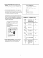
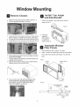
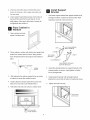
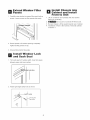
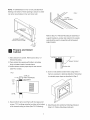
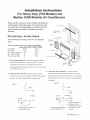
installation
instructions
For Heavy Duty (FAS Models) and
Median (FAM Models) Air Conditioners
Please read ALL instructions before installing. Two people are
recommended
is required,
to install this product.
If a new electrical outlet
have the outlet installed by a qualified
before installing
electrician
unit, See#5 in Preliminary Instructions
following.
Prelimi
nary
instru ctions
FOAM
Do the following before starting to install unit. See illustrations
below.
LOCKENG
Check dimenstions
of your unit to determine
Heavy duty (FAS)
Unit Height:
18,5/8"
Unit Width:
261/2"
Min. Window Opening:
19"
Min. Window Width:
31"
Max. Window Width:
43"
GASKET
WASHERHEAD
SCREW_._._
X
ASSEMBLY
model type:
(LEFT)
Median (FAM)
17.5/8"
231/2"
181/2"
26 Vj'
40 V2"
SIDE
RETAENER
J
1. Check window opening size- the mounting parts furnished
with this air conditioner
sill double-hung
are made to install in a wooden
window.The
standard
parts are for
BRACKET
window dimensions
of 1g"(483mm).
listed above.Open
sash to a minimum
(FIG. 1)
3.
2.
Check condition of window-
Check your storm windows= if you storm window
frame does not allow the clearance required, correct by
all wood parts of window
must be in good shape and able to firmly hold the needed
adding a piece of wood as shown in FIG.2, or by removing
screws.if
storm window while room air conditioner is being installed.
not, make repairs before installing
unit.
(continued)
FIG. 2
FIG. 1
//
_1SASH
SASH
f
19" MIN
1112
19" MIN
1/2" MIN
STORM
WINDOW
FRAME
OR
STORM WINDOW
OTHER OBSTRUCTION
FRAME OR
OTHER OBSTRUCTION
1
WITH TWO NAILS OR
SCREWS.
P/N 6612990 1162
4. CHECK
FOR ANYTHING
AIRFLOW
- check area outside of window
such as shrubs,
furniture,
THAT COULD BLOCK
trees, or awnings.
Inside,
Tools Required
for things
be sure
a large flat blade screwdriver
drapes, or blinds will not stop proper air flow.
tape
measure
adjustable
5. Check the available electrical service - power supply must
is 48"long.
Guide for serial plate Iocation.)Power
or pliers
pencil
be the same as that shown on the unit serial nameplate.
(See Owner's
wrench
cord
Be sure you have an outlet near.
_/
_/
Level
Socket
_/
Phillips screwdriver
wrenches
All models have a 3-prong service plug to provide proper
service and safe positive grouding. Do not change plug in
any way. Do not use an adapter plug. If your present wall
Hardware
(in plastic bag)
outlet does not match your plug, call a qualified electrician
LJty.
to make the needed change.
Locking Screw
Washer
Head
For
window
panels
::_i
Avoid fire hazard or electric
shock, Do not use an extensioncord or an
adaptor plug. Do not remove any prong
from the power cord.
2
HeadLong
Screw
3/4"
Hex-
Grounding type wall
receptacle
[_
_
Safety Lock
and Long
IocknutScrew
1/2"
3/4" Long Flat
Head Bolt and
Locknut
Power supply core
NIth 3-prong groundi
plug and current
detection device
Sill Angle Bracket
6. Carefully
unpack air conditioner
4 ea.
2 ea.
2
- remove a!l packing
material. Protect floor or carpet from damage. Two
locking screw for
top angle, side
Long
hex-head
retainer
5116"
people should be used to move and install unit.
Long
2
10
"ndow Mounting
g
Remove
Chassis
D
1. Pull down front panel and remove filter. (See FIG. 1).
2. Lil_ front upwards and place to one side.
1.
Install
Angle
and
SideTop
Bracket
Attach foam gasket to top angle above holes as
shown in FIG. 6.
FIG. 6
3. Locate the four front screws and remove. These screws
will be needed to re-install the front later. (See FIG.2)
4. Pry away front from cabinet sides as per photo (see FIG .3)
5. Gently lift front off unit and place to one side (See FIG.4).
2. Install top
angle and
side retainers
to cabinet as
shown in FIG. 6.
a
Assemble Window
Filler Panels
1.
Place cabinet on floor, a bench, or a table.
2.
Slide 'T' section of window filler panel into side retainer
on the side of the cabinet (see Figures 7-8). Do both
6. Removeshi ppingcrewsfrom top d unit and_tso on theside
by the base if installed.
7. Hold the cabinet while pulling on the base handle, and
carefully remove the unit.
8. Add two foam inserts to holes in top of cabinet where
shipping screws were removed from.
sides.
FIG. 7
PLASTIC
WINDOW FILLER
FRAME
PANEL
SIDE
9. Your unit may come with internal packaging.THIS
PACKAGING MUST BE REMOVED PRIOR TO
INSTALLING THE AIR CONDITIONER BACK
RETAINER
FIG. 8
INTO THE CABINET. (See FIG. 5).
PLASTIC
FRAME
TOP
VIEW
LOCKING
'T'SECTION
WINDOW
FILLER
PANEL
3
SCREW
HOLE
3. Insert top and bottom legs of window filler panel
M
frame into channel in the to angle and bottom rail.
Install
Bracket Support
Do both sides.
1.
4.
Insert washer head locking screws (2) into holes in
Hold each support bracket flush against outside of sill,
and tight to bottom of cabinet as shown below. Mark
top leg d filler panel frame (see Step 6). Do not
brackets at top level of sill, and remove.
totally tighten. Allow leg to slide freely. Screws will
be tightened
after Section 6.
Place
Cabinet in
Window
1.
Open window and mark
center of window stool.
MARK
L=ET
_.1/2"
'- r'_:_/i_N
.
D LOC _N UTS
LODKNUT !/
Place cabinet in window with bottom stool angle firmly
scated over window stool as shown. Bring window
down temporarily
LONG SCREWS
behind top angle to hold cabinet in
BRACKET---_
place.
/
I11//
_)'_
FLAT HEAD BOLT
_ <:_ _L/
2 EACH REQ'D FOR EACH
SUPPORT BRACKET
2.
Asscmble
sil! angle bracket to support brackets at the
marked position, as shown. Hand tighten, but allow
for any changes
3.
4.
Shift cabinet left or right as needed to line up center
of cabinet on center line marked on stool.
Install support brackets (with sill angle brackets
attached)
to correct hole in bottom of cabinet as shown.
Fasten cabinet to window stool with 2 screws into
holes.(You
5.
3.
later.
4.
may wish to pre-drill pilot holes.)
Tighten all 6 bolts securely.
Add bottom rail seal over screws to window stool.
Z_
Bottom
Rail Seal
--
o N
/o
_'
--
tong HEX+
HEAD SCREW
4
I/2" long screws
and Iocknuts
Extend
...........
Panels
1. Carefully
Window
install Chassis into
Cabinet and install
Front to Unit
Filler
raise window to expose filler panel locking
1, Lift air conditioner and carefully
leaving 6" protruding,
screws. Loosen screws so filler panels slide easily.
2. _DO
slide into cabinet
not push on controls OR finned coils.
3, Be sure chassis is firmly seated towards rear of cabinet.
4. Installation of front is the reverse of removal outlined
in Section 1.
2. Extend panels to fill window opening completely.
Tighten locking screws on top,
3. Close window behind top angle.
Install Window
and Sash Seal
Lock
1, Trim sash seal to fit window width. Insert into space
between upper and lower sashes.
OW SASH SEAL
2. Attach right angle safety lock as shown,
SAFJTY
LOCK
3/4" }orlg hex-
5
Thru-The-Wall
installation
NOTE: Consult local building codes prior to installation,
Carefully
or a qualified carpenter.
dimensions
measure
and cut an opening
depending
with the following
on your model. See FIGS, land 2.
This air conditioner has a slide-out chassis, so that it can
WIDTH "X" = inside model width plus twice the thickness
of framing material used.
HEIGHT "Y" = inside model height plus twice the thickness
of framing material used.
be installed through an outside wall as specified below:
Heavy Duty (FAS)
Select Wall Location
Heavy Duty(FAS)
Max wall thickness
IMPORTANT:
Median (FAM)
10"
8"
Median (FAM)
inside Frame Height:
18-_8"(47.9cm)
18" (45.7cm)
Inside Frame Width:
2@4" (67.9cm)
231J8"(60.6cm)
Side louvers must never be blocked.
NOTE: All parts needed for Thru-The-Wall
are provided,except
FIG. 2
Installation
a wood frame, shims, and 10 wood
screws (#10-1" long minimum). Select a wall surface that:
1, does not support major structural
frame construction
truss-bearing
loads such as the
at ends of windows, and under
points, etc.
2. does not have plumbing or wiring inside.
3, is near existing electrical
outlets, or where another
outlet can be installed,
4. faces, and is not blocked to the area to be cooled.
5. allows unblocked airflow from rear sides and end
(outside) of installed air conditioner.
8-1/2"
Prepare Wall
4. Build a wooden frame with the INSIDE dimensions
of
your model listed above. Measure twice remember...)
1. Prepare wall in frame construction
(including
brick
and stucco veneer). Working from inside the room,
find wall stud nearest the center of area where air
Frame depth should be the same as wall thickness.
Fill
in the space from the opening to the studs with wood
spacers, as shown.
conditioner will be installed (by sounding wall, or by
magnetically
finding nails).
2. Cut or knock out a hole on each side of center stud.
3. Measure between inside edges of every other stud as
shown in FIG. 1.
FIG. 1
3-3/8" MIN
(8.8 cm)
5, Nail framd to spacers to spacers with front flush with
dry wall.
'-NAIL
SPACERS
TO STUDS
NOTE: If wall thickness is 8-1/2" or more, add aluminum
flashing over bottom of frame opening to assure no water
can enter area between
FIG. 2
inner and outer wall.
1"LONG
SCREW
Refer to Step 4 d Window Mounting for assembly of
support brackets.A
ALUMINUM FLASHING
OVER BOTTOM OF FRAME
wooden strip nailed to the outside
wall should be used in conjunction
with sill support
angle brackets.
I
Prepare
Cabinet and Install
1. Slide chassis from cabinet. Refer back to Step 1 of
Window Mounting.
brakcet
2. Place cabinet into opening with bottom rail resting
firmly on bottom board d wooden frame.
3. Position cabinet to achieve proper slope for water removal.
(See FIG.1 below.)
5. Screw or nail cabinet wooden frame using shims if
FIG. 1
frame is oversized,
3/4"PLUS
THICKNESS
to eliminate distortion. Remember
to maintain proper slope as described
in Step 3.
SEE PARA 5
5/16"
TO
3/8"
LEVEL
'_
4. Secure bottom rail to wood frame with two large wood
screws
1"(2.5 cm)long using the two holes in the bottom
of the channel resting on frame.(See
FIG.2 following)
6. Install chassis into cabinet by following all steps in
Step 8 of Window Mounting.(continued)
7
OPTIONAL:
Caulking and installation
of trim on interior
wall may be done. You can buy wood from your local lumber
or hardware supply. On the outside, caulk openings
around top
and sides of cabinet, and all sides of wood sleeve to the opening.
NOTE:
See Step 7, Item 3 of Window Mounting
Instructions
for bottom rail seal location.
Masonry Construction
1. Cut or build a wall opening in the masonry wall similar
to the frame construction(refer
to Step 2 d Thru-the-Wall
Installation for a wall thickness
greater than 8-1/2").
2. Secure cabinet in place using masonry nails, or the right
masonry anchor screws.(Another
way to do this is to build
an in -between frame of2x4 's as shown in the Step 2 Prepare
Wall illustrations-but
make it double framed on either side,
and install between masonry wall opening and cabinet.
Frame must be securely anchored to masonry wal! opening)
This way gives very good louver clearance on either side of cabinet.
3. Install a linted to support masonry wal! above cabinet.
Existing holes in cabinet can be used and/or additions holes
can be drilled to fasten cabinet at various positions.Be
that side louver clearance is in accordance
sure
with Step 1above.
4. Install exterior cabient suppport brackets as shown in
Step 2 d Thru-the-Wall
Installation.Caulk
neede, to provide a wether-tight
of cabinet.
or flash if
seal around top and sides
5. To complete installation, apply wood trim molding
around room side projection d cabinet.
8