1
For help with your old Onan generator,
visit Smoke Stak
http://www.smokstak.com/forum/
forumdisplay.php?f=1
You will find "The Smart Guys" here, with
many years of experience repairing old
Onan generators.
3/21/2015
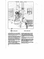
WARNING
THIS ELECTRIC PLANT MUST BE INSTALLED AND
BE OPERATED ACCORDING TO OUR INSTRUC
nONS. AN IMPROPER INSTALLATION OR THE USE
OF OIL OR FUEL OTHER THAN THAT RECO~
MENDED IN THIS MANUAL, RELIEVES THE MANU
FACTURER OF ALL RESPONSIBILITY FOR PLANT
PERFORMANCE.
READ THIS SERVICE MANUAL CAREFUllYI
P,.. t(TED IN U. II. A.
t
,-~
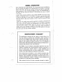
IMPOR TANT!!! USE OF LEADED FUELS
The performance of gasoline engines deteriorates with use until
it eventually becomes necessary to remove the carbon, grind
the valves, install new spark plugs, etc.
Lead is added to many gasolines to increase the octane rating.
Due to the action of the lead in the combustion chamber, on
the vaive seats, and on the spark plugs, the use of such fuels
causes the engine performance to deteriorate more rapidly. When
using highly leaded fuel, there is a regularly increasing lead con
tent in the crankcase oil.
.
If the gasoline contains .~~ cubic centimeter; or less, of lead per
gallon there is little such effect. However, as the proportion of
lead is increased the deterioration in engine performance is
greatly accele~ated.
Under normal operating conditions with unleaded fuel it may
be necessary to remove carbon each 1000 operating hours, grind
valves each 1000 to 200Q operati·ng hours, clean spark plugs each
200 operating hours, and change crankcase oil each 100 to 200
operating hours.
When using Army 80 octane fuel, aviation 100 octane fuel,
or other fuel containing more than 2 cubic centimeters of lead
per gallon, cha
the crankcase oil each 50 operating hours..
When using suc
hly leaded fuels it may be necessary to remove
carbon and grind valves each 100 to 200 operating hours, clean
spark plugs each 50 operating hours, and .replace them each 100
to 200 operating hours. If carbon is removed every 100 to 150
operating hours, the periods between valve grinding jobs usually
can be considerably lengthened.
When using leaded fuels, inspect the engine more often and give
it the more frequent service required.
.
1
~
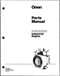
GENERAL INFORMATION
THE PURPOSE OF THIS BOOK. This instruction book is furnished so
that the operator may learn of the characteristics of the plant, A thDrough
study Df the book will help the Dperator to keep the plant in good ope~
ating condition so that it will give efficient service. An understanding of
the plant will also assist the .operator in determining the cause of trouble
if it occurs.
KEEP THIS BOOK HANDY. Such simple mistakes as the use Df im
proper oil, improper fuels, or the neglect of routine servicing may result
in failure of the plant at a time when it is urgently needed. It is suggested
that this book be kept near the plant sO' that it may be referred to when
necessary.
SERVICE. If trouble occurs and the op,erator is unable to determine the
cause after a thO' rough study of the book, or if he is unable to determine
'what repair parts are required, the manufacturer will, _upon request, fur
nish any adv.ice needed. When. asking for advice, be sure to' state the·
Model, Serial, and Generator numbers of this plant. This information is
absolutely necessary and may be obtained from name plates on the plant.
Be- sure to give all other details available.
I
I
MANUFACTURER'S WARRANTY
The manufacturer warrants each new engine or electric plant to be
free from defects in material and workmanship. Under normal use
and service our obligation under this warranty is limited to the replac
ing of any part without charge which, within ninety (90) days after
delivery to the original user shall be returned to us or our authorized '
service station with transportation charges prepaid, and which our ex
amination shall disclose to have been defective.
Our liability in case of defective workmanship, material or any costs
incurred in remedying any claimed defective condition in any unit or
such unit having been repaired, altered, or which installation and
service recommendations have not been complied with is limited
strictly to the proper adjustment authorized by the factor;.
This warranty does not include or cover standard accessories used,
such as carburetors, magnetos, fuel pumps, etc., made by other manu
facturers. Such accessories have· separate warranties made by the
respective manufacturers. Repair or exchange of such accessories will
be made by us on the basis of such warranties.
This warranty is in lieu of all other warranties e~pressed or implied.
I
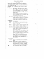
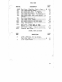
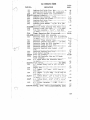
IABLE OF CONTENTS SUBJECT
Specifications En.gine Details ................................................... e".
Generator Details .....................-.............................. .
Controls .......................... ".............................. 4i ................ e' .- . . . . . . . ., ..
Installation
of Power Unit Location ........................ .,".......................................................... ;. ..
Ventilation•••••••••••••••••••••••••••••••••••••••••••••••
Mounting Base ................................ ;, .......... Ii .............................. a,a .... .
Accessories ................................................. .; ........................... "........... ..
P'u.el Tank. .......................................................................... ~ .......... ..
Exllaust Syert"em.......................................................................... ",* ...... ..
Grounding ..... .; .................. ~ ........ :. .............................. -. ......... .
"in IJ.nes ••••••• ~ ~' •••••••••••••••••• '•••••••• ~ ••• '. ....... .
Batteries ••• ., ••••••••••••••••••••••••••••••••••••••• '• •••••
1
2
2
3
3
.3 6
6
6
6
6
6
Preparation for Operation Inspection:~ ••••• '• •••••••••••••••,••-. ~ ••• ,. .................. ~
Coolin'g' System•• "• •••••••••••••••••••• ~ • '................... ..
Lubrication •••••••••••• ~ ••••••••••••••••••••••• ~ •••••••••
Spa.rk Plugs •••••·••••••,••••••••••••• e••• e••••••••••·• e••••••
Fu.el.................................... '• •••••••••••••••••••
Batteries ••••
/II • • • • • • • • • • • • • • • • • • • • • • • • • ,• • • • • • •' • • • • • • • • • • • • •
Operation Starting the Plant••••••••••••••••••_••••••••••••••••••••••
Connecting the :Load. ,•••••••••••••••••••••••••'•••••••••••••
Stopping the Plant.; ••••••••••• '• •••••••••••••••'••••••••• '• • '
Abnormal Operating Conditions Cold We'ather -Operation••••••••••'•••••••• ~ .,.'.' ••••••••••••••
High Temperature Operation ••••••••••••••.•••••••'••'•••••••••
Dust or' Dirt ...·• ••••••••••• '••••••••••••.••••••••••••••••••• '!,
Control System
. .
.
Self Starting•••••••••• '• •••••••••••• -: •••••••••••••• '• ••••••
Remote Control•••••'. '••••••••••••••• e•• e••••••••••'••••'. '. e'••)
Emergen'cy ·Starting·•• ·• •••-••••••••.••••• e ••••••.•••••.•• ,• • • •-. ~'.
Maintenance
.
.
~ • '. :. • • • -• •' • • • • .: • • • • • ~ ........ '. . .
·Maintenance ••••••••••• '• • ~' •••••••• '. ..........'••••• ," ••
Daily Maintenance••••••• e
.......
Weekly
Monthly Mainten·ance ••"••••• ,. •••".......... ~ ........ 4. '••••• '.' •••.•
Six Months Inspection........................'....'• .: .'••••••••
'Gerter&.l .Trouble Causes ••••• e· • • • • • • • • • • • • • • • • • • • • • • • • • • '• • • • • • ,.'• •
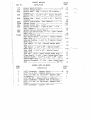
Accessory Service 8
8
8
10 10 10 11 11 II 12 1:3 13 15 15 15
16 16 17 17 18
" Carburetor ......................... "•••••••'. ~ •••.•• '.'. '•••".'.......... .
Air CJ.eanere,~ ........... ~.' ••••••••/•.•••'.'.-."••••••.•'.,•••••••••-•.~"
Automatic Cho'ke.~ ••••••••••••• 411 • • • . •· ..
\'~
SPEi rk ~.l ugs .,' •••••"•••'........... ~ ••'•••••'••,........."...........~ ••'
Distributor •• .-~ ~ • '. '•.• ~' ••••••'.-•••• ~ ••••;••••• ~.:••••• ';'. e'••.•.•••
Ba t tc:ry Ca;l:-O and Att,elltion ••••••••••••••••••••••••••••'•• .- •. '
Governor - Internal' Type •• 4! •• 411 . . . . . . . .' . . . . . ~ • • • • -., .!" 411;.411 .,,~:;."
22 2:3 24 fuel Pump.'................... ...........".........'.... . . ',.. .
:n e. . . . . . ' • • • • • • ' • • • • •,. . . . . ' • •
••'
20 21 22 22 Governor - Externa1 Type ..............'. _••••••••••••••• ,~,._.~ .... . 26
,~
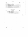
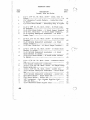
TABLE OF CONTENTS CONTID SUi3JECT Engine Service Diagnosis ••••••••••••••••••••.•••••••••'••••••• Yearly Engine Servicing•••••••••••••• Disassembling Engine.,•••
Valve Grin~ng •••••••• ~ ••••••• ~ ...... ~ ................... .
Tappet .Adjustment••••••••••••••• e • • • • • • • • • _• • • • ~ • • • • • • . • •
!11' . . . . . . . . . . . . . . . . . . . . . . . . . . . . . . . . .
Carbllrstor............ ~ ....
'*,
*' *' ••••-. . . . . . . . . . . . . . . . . . . ~ ..... e *'
Cool.ing.......... !I . . . . . . . . . . . . . . . . . . . . . . . . . . . . . . . . . . . . . . . . . . .
Governor Adjustment ••,......................................
Table of Clearances ••••• '. ........ ~ ...................... .
MAJOR ENGINE OVERHAUL................ ·. ...........................'••
Generator Service
Generator Disassembly.............................. •.••••
Reassembling the Generator •••••••••••• ~ ••••-•••
Storage
. .
Preparation for Storage••
Wi thdrawal from St-orage ••.•'. • • .. • • • • .. • .. .. • • • .. • • • • • • • • • • • .. • •
Instructions for Ordering Repair Parts.......................
ReJ>8.ir Parts IJ.at '• •• e • • • • • e ..... ·e
0••
0
•
•
•
•
•
•
•
•
A..............................
o
•
•
•
•
•
•
•
•
•
•
•
•
..
•
•
•
•
•
•
..
•
•
•
•
•
..
..
..
•
•
3,Q .3.3
34
.34
.34
34
35
36
43
45
46
46
48
55
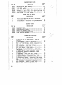
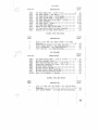
LIST OF ILLUSTRATIONS
SyBJECT
Proper installa~ion ••••••••••••••••••••••••••••••••••••• e •• ',.
Plant Base ......................... e • • • • • • •;• • • • • • •' •• e • ~ • • • • • • • • •
Underground Exhaust lufflar ••••••••••••••••••••••••••••••••
Oiling SysteJll..." ............... '. ~ ••••••••••••••••••••••••••••
Control Parts •••••••••••••••••••••••••••••••••••••••••••••••
Accessory Service She~t •.•••••••••••••,•.•••••••••••• "••••••• ·• ••
·Carburetor••••••••••••••••••••••••••••••••••••••••••••••••••
Governor - . . .I?-ternal Type ............,' .............._••• ~ ••••••••
Gov,ernor - Ex.tern.al Type ___ ••••••••••••••••••'_ ••• -• ••,_.••••••••
,Fuel PU.mp •.••••..••••••••,••• _•••• _., •••••••••• -• ••••
Cylinder .and Valve Service••••-••••••••••••••• e,• • e • • ,• • • • • • • • •
Flywheel- ,Puller Assembly••••,.,•. e •• ~ • • • • • . • • • • • • • • • • • • • ~ • • • • •'.
Alternating .Current Generator Assembly •••••••• '•••••
Care of Commutator and Brush.es, ••••••••,••••••••••••••••• ~ ••••.
WiriJlg Dia~a,Ig. ............. e • • • • • • e • _. . . . . . . . . . . . . . ., • • • • • /11' • • . • • • • •
Repair Parts Illus.trations
:En.gine Parts •••••••• _• e' . . . . . . . . . . . . . . . . . . . . . . . e • • • •
e •
'Engine Ac.cessories • .-••••,•• *' ....,••••••••••••••,••••• ~ ••••• ,
Carbu.retor....... e • • • • • • • • • ~ . . . . . . '• • • • • • • • • • • • • • • • .: e . . . . . . _
Genera tor ••• ~ •••••'• •• '• • .- •• '••••• _••••,•••••'•••••••,.' ....... .
0• • ' • • • • • • • • • • • •
0,0 • • • • • . • •
o• • •
Contro;L ... " •• ~ ••••••••• -._ ••••••••• .-...................... .
Cross Section View ••••••• ~ ••••••••••••'•• Center of Book
4
5
7
9
14
19
20
24
26
27
.31
.38
40
40
47
49
50
52
5.3
54
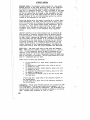
SPECIFICATIONS Engine - A four cylinder, four cycle, L head, water cooied engine
is used in this plant. Two blocks of two cylinders each.are
mounted at a 90 0 ' angle from one another .on a common crankcase.•
The cylinder bore is 3", the stroke 2-1/411, the piston displace
ment· 77.8 cubic inches, and the compression rat.io is 5-1/2 to L
Due to the V design, the engine develops 14.5 horsepower within
an overall length but-slightly longer than a two cylinder engine
with half the power.
CyJinder heads and cylinders are reJuoveable. The crankcase can
be separated frolll the cast iron oil and mounting base. Inspection
plates are located on either side of the crankcase.
Cast iron three ri,ng (2· compression and l oil control) pistons are
used. Connecting rods are drop forged steel with replaceable
steel backed babbit liners. Tne crankshaft is also drop forged.
Main and camshaft bearings are steel backed babbit. The main
bearings are pressed into bearing plates bolted to the' crankcase
and line-reamed. The camshaft bearings are pressed directly in
to the crankcase and then lin,,-reamed.
\
Two types of governors can be furnished. With one, the governor
mechanism is an integral part of the camsnaft timing gear. With
the other, a.n industrial type governor is bolted to the front
gearcase and is driven by the camshaft gear. Neither type should
require allY servlclng or adjusting unless they rillve been tamper
ed with or the engine has been disassenlbled.
The downdraft carburetor is equipped with needle valves. The
choke is either manual or autolt1atic. In 'the latter case, the
automatic element is mounted on the carb1,lretor choke valve shaft
and controlled by a thermostatic coil actuated by an· electric
element. The air cleaner mounts 011 the carburetor intake and
draws air thru a conduit to the front.of the radiator. A coru1ec
tion between the crankcase ventilator and the air· cleaner draws
oil fur(,es back into the engine. thru the carburetor. where they
help lubricate the upper cylinder walls and valves.
Spark plugs and high tension cables are sllielded to prevent ra
dio interference. Ignition current is supplied either from a
battery thrucoill3 and distributor, or from a magneto .driven
from the canlshaft.
A gear type oil pump furnishes pressure lubrication to the niain
and. connecting rod bea;rings.· Spray frau the ends of the. oear- .
lubricates the pistons, valves, and either wea.ring parts.
An oil drain is located in the base. ,A bayonet type oil level'
gauge extends thru the right ha.nd inSPection plate. Oil capacity
is 8 quarts.
The cooling system is of ,the thermal syphon tyoe having acapa
city of 17 quarts. The fan is four bladed andnas an oil lu
bricated)1ub which is driven by a V-belt at 1-1/10 times engine
speed. Air is ,discharged. or pushed out over aradlator located
directly in front of the fan.
1
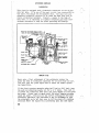
SPECIFICA'J:'lONS
ELECTHICAL ~~~
The generator is a standard, four
self-excited
current type with the frame bolted to an ada)Jter ring
enginecJ'i~nkca3e.
The arwature Is coupled to'the fly,v[leel
by. 11 metal disk type
which serves as a solid dd ve melu
ber and at the sr:une time accominodates i'.l1;Yiaisillign"ent oetweeh
the engine an,d the generator. The reHr main crankshaft bearine
supports tJ1e forward end of the armature, ,Hid the outboard erld
is carried in a grease 5ee.led ball be:c',ring.
Both ultBI'nating ami direct current are oroeluc'ed. Windlngs for
both
of current' are \\found on the saUie armature shaft and
pieces. The direct current is t~lken frou! an over81~',ed COlll
and tile
current from
brass col.Lector
by carbon brushes. The dJrect current is used to excite
the alternator stator coLLs, and
in the cc:we of the selfstarting models, to keep the startine -oatteries charged. 'j~rle
exciter armature winding acts as a motor to crank the engine.
All the
of the generator have DeBn heavily impregnated
with insulating varnish and thEm baked to provIde rnaximmn pro
tection against moisture penetration. The
is suf'l'iciently
insulated to operate in 113.11 t,)Tpes of weather H1Jd in all climates,
from the tropics to the arctic. However, the plant should be
sheltered as mush as possible as i t
to entirely
pro,tect
corrosion, and any
operated in
hmnid
countries should be serviced more
than is normal.
The generator frame is a rolled steel ring machined on the inside.
The pole pieces are punched from lamina,tions of 22 gauge electri
cal steel. The arl1iature laminations are punched from -26 gimge
electrical steel. A cool:i.ng fan is bolted to the engine end of
tlj.e arflature and it in turn bolts to ,the flywheel. Cooling air
is drawn in thru vents in the
end belloan(i,
over the ,brushes, COlllmutator
rings, and
ture and field windings, and is then forced out thru
in
the
casting at the engine end of tl1e ge];lerator.
The generator is shielded to minimize radio interference. 1 t is
rated at 5000 watts, 115 volts, 60 cycle alternating current.
and, operates within a 40 0 Centigrade temperature rise.
CONTROLS
~~== _=-===~.
-
These plants are equipped vvi th a crank for starta
button for stopping. Ignition is furnished by a
gear driven magneto with an impulse coupling to insure easy start
The c8.rburetor is illanually choked.
Hemote .Control' Plants - Tl1ese plants can be_ started electrically.
by pushing a button either. at the
or at a relJlote control
station which can be set
at any point within 250 feet of the
plant.
may be
of the magneto or the battery
distributor type. An autonk"l.tic choke properly controls the lJlix
ture of fuel and air
.
the carburetor. Stop buttons are
also located at the
and at the remote control station.
In case the
reason the hand cr.ank
ally.
2
batteries are
or if for
not start when the. button is
furnished, by which the plant c,m be
af!y a
manu
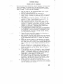
INSTALLATION
The proper installation of the plant is absolutely necessary for satisfactory
and. continuous service. Location, ventilatio.n and temperature are amo.ng the
main facto.rs to. consider.
LOCATION - The plant should be lo.cated centrally with respect to the electrical
equipment it is to. o.perate. This allo.ws the use o.f small ,size current carrying
wires. As a result there is less vo.ltage loss, the equipment o.perates mo.ra sat
.isfactorially and the entire system is more efficiern:..
The location sho.uld be .such that the air is not dirty or extremely humid. If
co.nditions can not be avo.ided, the plant should be inspected mo.ra eften.
Also. take any preventive' 0.1" corrective measures necessary. Sub-ground levels
are ·to be avo.ided because o.f dampness, poor air circulatio.n and pes sible coll
ection of dangerous exhaust· gase~ leaking from.the line.,
.
th~se
~f the plant is to. be permanently mourn:.ed, a base sho.uld be built and the en clo.sure sho.uld be at least 10 feet square. If it is to. be o.perated as a port-
able
a sub-basesho.uld be pro.vided and the plant pro.tected against extreme the elements. If installed aboard ·mo.bile vehicle, the co.mpartment large as pes sible and sufficient
o.penings pro.vided. VENTILATION This is an impo.rtant facto.r as
engine generates a . great deal o.f ·heat which must be dissipated. Overl,e~tti.n'" will reduce the effi-'ciency and may cause dsmage to. the plant. The air that circulates must be clean. Otherwise it will deposit the dirt en the
This will act·as a,blanket and reduce the cooling so. that the plant overheat. The plant sho.uld be installed at least 24" away fro.m any wall o.r air circulatio.n barrier.
is mo.unted in an .enclo.sure,air intake
d~scharge o.penings sho.uld
They should be at least 1-1/2 times
size o.f the radiator. The
air
sho.uld be as clo.se to. the plant 'as po.ssible. Both types o.f o.penings
sho.uld be shielded with a screen and lo.uvres. A thermal ventilateI' in the fo.rm
o.f a cupo.la o.r stack can be built into. the ro.ofto. pro.vide no.rmal air circula tionwhen the plant has shut do.wn. Additio.nal ventilatio.n precautio.ns must be o.bserved when the plant is mo.unted abo.ard a vehicle. Usually the co.mpartment is small so. that more o.penings have to. be pro.vided. These c,:..n be directly abo.ve the cylinders,o.ppo.site the fan 0.1" in the fleer. 'In extremely co.ld weather the temperature o.f the enclo.sure can be·co.ntro.lled by
clo.sing off the o.penings and allo.wing the 'heat o.f the plant to. heat the room.
No.rmal temperatures can thus be maintained. When used as apo.rtable \J.nit, "ome
type of wind barrier o.r tempo.rary.walls sho.uld be used to. keep the plant at the
correct o.perating temperature.
MOUNTING BASE If th~ plant.is installed
en a base, it sho.uld be
high
fro.m the flo.or to. allo.w easy access to
o.f the parts, and to.
guard
damage which may be caused by bumping the plant wlthother o.bjects.
The base sho.uld be from 9" to 12" high. The plant should never be belted so.lidly
to any fo.undation. Shock abso.rber mountings are pro.vided to. prevent vibratio.n .
fro.m reaching the pl~t.
3
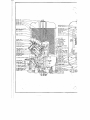
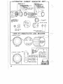
....------PROPER INSTAllATION-----,
!'ROPER VENTILATION
V~"
•
A PROPERLY INS;~LLED ELECTRIC PLANT fOil PERIIANENT '
AfREEflOW OfCLEAM fRESH AI·R MUST BE AVAILABLE.
INSTALLATION SHOULD BE SET UP II AWELLV£NTlLATED
fROM SUITABLE WiNDOWS OR OPENINGS IN THE WALLS
ROOIUiFAMPLE SIZE (AT LEAST 10'X lollliSTALL PLAIIT
, THROUGH AND AROUND RADII. TOR AND PLANT. SKE TCII
AT LEAST Z4" AViAY FROM WALLS TO ALLOW EASY ACCESS
SHOWSAVERY SATiSfACTORY ME.THODOf AIR CIRCU
LATION. WITH AIIPLE PROTEt TION fRO II OUTSIDE ELEII
TO PLANT FOR STARTING OR SERVICI NG.
EilTS.· DO NOT OPE!lAIE YOUR PLANT IN ACLOSED ROOM
RUBBER SHO~K ABSORBIII(' BUSHIIIGS FURNISHED WITH THE
AT ANY TIME.
UIIIl SHOULD BE sn UNDER THE PlANT TO PREVENT THE
OPENINGS OR VEIITlLA101lS SHOULD BE AT LEAST loxia
S,LIGHTEST VIBRATION. SHOCK ABSORBING VALUE Of BUSH
INGS WILL 8E GREATER If NOT BOLTED noWN TOO, TIGHT.
WITH LOUVERS. COV.ER VENTILATORS OROPEIiINGS·'itntl
LA RGE MESH SC REEt!.
EllHASl PIPE. BATTERY AIID LINE COliN EC.TIONS ARE 011
If PlANT IIUST 8E I NSTAL.LED IN BASElIENTBE SURE TO
OPPOS IT.E SIDE OrTHE UNIT AS SHOWN ABoVE. EXHAUST TUB
ING CAN BE RUM EITHE R DIRECTLY TO THE OUT SIDE Of THE
PROVIDE EllTIIA CELLAR OPENINGS fOR THE AIR CIRCULATION
BUILDING 011 IIiTO All UNDERGROUND EXHAUST, CHAMBER If
NEEOED BY PlANT. BASEMENT LOCATIONS ARE NOT RECOM
MENDED BECAUSE Of DAMPNESS AND POOR AIR CIRCULA
EXTREME SILENCEIS DESIRED.
TION, - ALSO EVEII A SllGllT AIIOUNT Of MECHANICAL
t&l.Ill!I-ALL E:XijAUSTCONNECTIONS MUSl BE TIGHT AS
NOISE IS USUALLY OBJECTIOIIABLE.
.
LEAK'AGE OfEXMAUST fUMES WHICH CONTAI N POISONOUS
no NOT INSTALL YOUR PlANT IN A HEN HOUSE OR BARN.
MONOXIDE GAS IS EXl REt.lELY DANGEROUS.
(FEATHERS, MAY OR SlllAW WILL. CREATE A FIRE HAZARD
If .PLANT ",",ST BE INSTALLED IN 'BASEI!lEIIl; INSTALL A
AND ALSO DAIIAGE YOUR ENGINE).
WATER TIIAP TO lAKECARE Of CONDENSATIOIIINTHEEX
"AUSf PIPE. DO NOT atlNUHAUST PIPE OVER TWENTY
.' .
nET
4
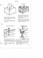
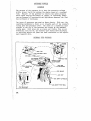
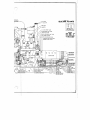
PLAN'!! BASE
CONCRETE BASE
CONCRETE FORM
r-~3"-+100~
Above base' dimensions are a minirnum'
and ma.'f' be lar-ger. Keep sa'lle bolt
The base must be at least
any wall.,
Use 4
3/8" x 9" bolts. See that
they extend 3-1/2" above the top of
the concrete.
MOUNTING BOLT SUSPENSION
A form, should pe built Into which
theconc;:retecan be poured and al
lowed to harden. The fOrm
be'large enough so base wi.ll
the lninunum size,;
A Iliixture af 1 part cement,' 2' p,uts
sand and l,parts gravel or crushed
st.one 'maybe used. Fill form", tap
dovmbut do riot move boltS"., : Allow
tD harden for three di:tys. ,
RUBBER.
BUSHING DETAILS
~3/8"'t4vT
~ 3/~(1
WASHER
~3/8"BOL'l'
l~RUlJBER,
PAD
~NC_SASE
Suspend mounting bolts from cross
cleats, nailed to- the top 61' the con- ' Use the rubber 'uountirlc1' bushings supplied
with the plant.
crete form before 'Jouring concrete.
one bushing between plant and 'base
P]'ace,large washer under head of bolt
bushing' "fits in recess in plant.
and adji,lst for proper height - .3-1/2" so
Set Plant
place. Assal,ble balance
mounting 'as shown above.,
Be sure top of f6unctation is level
nuts but not so that busliings
andau;ooth to prevent plant' base
or compre~s.
breakage.
of,
~~~
--------
,
INSTALLATIONS
All accessories nece'lsary t9 put the plant into immediate serv
ice are included with the plant. However, no main J..ine wires or
switches are furnished. These must be· purchased to. meet the
individual requirements of each plant. If special conditions
are encountere9, additional eq~ipment may be needed in addition
to that furnished, and this, too, must be purchased.
FuelTank - A standard fuel tank is furi'iished with each plant./
If the tank is not mounted on the plant,a flexible fuel line·- .
must be· used to connect the tank to the eogine. If a larger
tank is desired, an underground tank [email protected] be used i f the plant
is to be permanently installed. A suggested t~nk is shown on
the next page, but check the underwriters instructions before
making this installation. The lift from the tank to the plant
should never be greater than 6 feet, nor .longer than 25 feet un
less a separate fuel pump is used. Be sure that the tank is·
well vented.
EXhaust System - Flexible exhaust tubing and an automotive type
muffler come .with the plant. If the exhaust line passes thru
a wall, shield the wall by passing the tubing thru a: metal flange.
Iron pipe can be used in place of the flexible tubing, but at, ..
.least 12" o.f the tubing should be inserted between the pipe and
the plant.. 'Inc'rease the size of the tubing or pipe one size for
evefY six feet in length i f the line is to extend over; 10 feet.
All exhaust connections must be; tight and free from leaks. Car
bon monoxide fumes are poisonous and extremely dangerous. Be
esp~cially careful if a sub-ground level installation is used,
because carbon monoxide is also heavier than air.
The exhaust Hne should slope downward from the plant. If it
must be pitched upward, a condensation trap should be installed
close to t.he plant. Ariy type of fitting which will collect the
condensation of moisture ir:t the line can be used, . and i t should
be inspected and drained often. An underground exhaust muffler.
Refer to the illustra~ion din the following page for details.
Grounding -. The. plant should always be grounded. This can be
done by driving a grounding rod or 1/2" pipe .into the ground
near the plant. Connect either the negative (-) battery post
or the neutral (White) main line wire to the ground with a #10
or 1112 wire and a ground clamp. Never use a radio ground, .and
do not ground the plant itself.
Main Lines - .External wiring should be of the correct size and
sufficiently mnsulated to protect both the plant and the opera
tor. Consult the· local code before making the installation. A
main line fused switch or. circuit breaker should be installed
in the line 'near the plant.
Batteries -When batteries are used with the plant, they should
be set on a wooden frame or mat and connected to the pl~ntwith
the cables furnished. The polarity markings of the battery_ posts
and panel terminals ~ust be observed. See Battery Preparation
before connecting the batteries.
6
PIT NU5T e£ I.AIifJE ENOII6H
TOALLOJII-ArLl'A5r:'6 INCII£S·
CLEARIiNcE ON TOP. "OTTOM
AN£) :J/[)IfS or TIIN/( I"OR
5AN£) OR L()():JIf GRAYS/.
,UNDERGROUND FUEL TANK V{,NT :J}{()(/I.O' 1M PROTECTED
TiI'Ol'1 WCATllcR BY (;OO5c
NECK IfIITIl SClfct:NI!O
,OPE/r//r6 -PA'EI"EIfIlBLY
'lINDER EAVE 01" R'(JO,!';
PltEPAHATION
Jlfterthe plant has been installed in the proper location and on a mounting base', the following pam graph will outline the, pre
parationnecesdar-.f he,fol'er.utting the plO-nt
operation. Inspection
Check all fittings ,bolts, and nuts. Tighten ,my mec.hanical or eiecti'ical connecticins which ,may be loose. Visual ly inspect the I:ilant. Replace any ,parts which may have been dam aged. Cool~
System
A thermal syphon type cooling system is used on this r:lll.nt. Water rises' when it is heated; a.nci as the liciUid in the cylincier block and head becomes warmed, it rise,S tb the top of the radiator. Cooler water'from the bottom of the radiator takes its
and
turn becomes heated. Air driven Qy the fan over the radiator surfaces and fins cools the water in the radia.tor and, a con:;;w.nt circulation is ;thus maintained. 'rhe capa
c'ity of
cooling system is 17 quarts. Use only clean water or anti-freeze in the system. Rain water can be used, but salt water or alkali water will cause cf):!:-rosion in the radiator and should never be used. Check all hose and block connections and tighten' any that are loose.· Fiil the radiator to a point somewhat below the level of the overflow pipe to allow for expansion of the li quid. .Test the tension of the fan belt. A properly adjusted . belt can be moved inward or outward about 3/4". V-belts do not rec;uire the tension to prevent slipping that
belts do and a too tight belt will cause rapid WSqr of the fan hub. If ,the belt requires arijusting, loosen the cap screw holding the fan support arm to the cylinder vrater outlet and turn the adjustment stud screw in or 'out to increase or decre,ase the tension. Lock the adjusting screw and retighten the fan support arm when adjustment has been made . . The cooling system can be draine,d b<J opening the petcocks at the
bottom of the radiator support casting and at the .Viater inlet el
bOYls on .the bylinder blocks.
Lubrication· Fill the crankcase with 8 quarts of a good 'gr.ade of lubricating oil. Use an S.A.E. #20 oil if the temperature ranges between 50 0 and 800 Fahrenheit. Use an S.A.E. 1/10 oil i f the temperature is below 500 • If the temperat,'re range is above 80° or below '100, check the section on nAbnormalOperating Conditions" for the proper grade of lubricant. C
'
The.
,:ls indica ted~~Dy a bayonet type oil gauge extending from
r:ir;htha~d crankcase inspection plate. Check the level daily, malntainine the+evelbetween the l! full " and the Illowl! marks on the gauge. NJver:'allow the level to drop below the n,low" . mark. Places€ J 'v:€ i ral:dropso.f
lubricating oil on the joints of the link age between-the governor and the carburetor, and on the carburetor 'throttle and choke shaft bearings. E.emove ,tneplug .in the fan hub and fill the fan
relOl,ivoir to the point of overflowing. Remove the cover and filter element fromt.he air cleaner:. Fill the body of the 'air cleaner to th~ level indicated with new oil of the same visiosity as that used in the, orankcase. 8
..~,
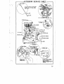
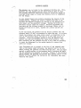
...-----.;..---W4A OILING SYSTEM ~---..,..--.........,
THIS SKETCH ILLUSTRATES tHE OPERATION OF tHE MODEL V-45
FULL. PRESSURE TYPE GEAR DRIVEN OIL·· PUMP. - OPE NARROWS
INDICATE THE DIRECTION. OF OIL FLOW FROM OIL PUMP THROUGH
DISTRIBUTION BLOCK TO FRONT AND REAR CRANKSHAFT BEARINGS.
EXCESS OIL PRESSURE OPENS VALVE IN. DISTRIBUTION BLOCK
ALLOWING OIL TO ESCAPE THROUGH PRESSURE RELIEF OPENING
TO ·OIL BASE. PRESSURE AT WHICH VALVE OPENS MAY BE REG
ULATED WITH PRESSURE RELIEF REGULATING .BOL T.
TO DISTRIBUTION BLOCK
PREPAHATION Spark
spark plugs and crank the enGine several
times. Rust inhibitor was placed in the cylinders for protection
before the piant
the factory. Being an oily liquid, i t is
very apt to foul the spark plug points making starting difficult •.
the points anti replace the plugs. .
- Any good grade of gasoline between a range of 67 to 8U
octane can be used, either leaded (ithy1) or un leaded. A leaded
fuel will give more efficient operation by allowing the ignition
timing to be further advanced wit.hout knocking or pinging. I t
also has less tendency to form carbon. However, it will event
ually form a coating over the internal surfaces which, in the
case of the
P.lugs·, may cause .hard starting. Proper main
tenance of the engine calls for periodic inspection and cleaning
of the spark plugs, and if followed, this
trouble will
never develop.
Check the connections running between the fuel tank arid the car
buretor. On plants having a mechanical fuel pump, .the pump will
be located on the left side, of the crankcase below the cylinder
block. Check the connections at the pump, and be sure that the
glass filter bowl is securely tightened and that
seats proper
lyon the gasket.
The fuel pump is equipped .with a manual operating handle. Use
this handle to pump gasoline to the carburetor at any time the
gas tank has run dry. It will save battery wear or a great deal
of hand cranking, and can also be used to check the operation of
the fuel pump.
Batteries
Check the connections to the batteries. The positive
(+) terminal at the control box IllUSt be connected to the posit}ve
(+)
of one battery. 'I'he negative
) terminal of the control
box must be connected .to the negative (-) post of the second bat
tery. Then the negative (-} post of the first . battery and the
Dositive (+) post of the second should be connected together. If
these connections are reversed, the batteries would soon be dis
charged and would eventually be ruined. Cover the terminals with
petroleum Jelly to prevent corrosion.
Check the electrolyte or acid. in the cells of the battery. I f the
batteries were received in a wet charged condition and the level
of the electrolyte is low, add distilled water to bring the
of the solution over the plates. If the batteries were received
in a dry charged condition, add electrolyte to tnebatteries accord
ing to the instructions attached to them.
10
-:.!.,
OPERATION
===,,-,THE
plant, be. sure that the plant has
been properly installed, that lubricating oil, fueT, and cooling
liquid has been beEm added, and. that proper ventilation ande!x
haust has been provided. Be sure that all the previous instruc
tions on preparation have been. followed:
Open the disconr:ect switch on the. main line.
Plants
Insert the crank thruthe openihf:in the rHa~a
p,rille and engar,e it witl1 the crarlkshaft so i t can be pulled
upwards. With a strong upward purl, turn the engine over. Do
not spin the crank and never take too tight a grip.on the crank
handle. Hold the crank in such a .manner that if the
back
fires, orkiclcs back, the handle will be
from your grasp.
While cranking the pl&.nt, partially close the choke valve. in
cold temperature, completely close the choke to obtain a rich fuel
mixture. In average temperature, or when the engine is warm,' only
slight choking will be required. Avoid too rich-a mixture or
flooding of the carburetor.
if-the engine does not, start, repe,~t, the Process • If it ,vill not
start after several attempt, check the ignition system, fue1-suppiy
position of the fuel shut-off valve; etc. With a miwplant, or·
one which has not been used for some time, several cycles of crank~
ingmay be necessary to bring fuel to the carburetor.
wI'henthe engine has started, vary the choke adjustment until the
'engine has warmed
Grailually open the choke valve until the
full open position
reached ,with the engine running satisfactor
ily.
Plants - Press the "st/'!.rtll button and hold it dovm
then releaSE? it. ii.epeat this procedure
until the plant starts, 'allowing about 10 second R between attempts.
If the plant does not start after several attempts check the .fuel
. and ignition systems. An autoJna,tic choke is mounted on the car
buretor, and no manual choking is necessary.
In. an emergency, if the electric start system fails to start the
plant, or the startirig batteries are low, the plant may be start
ed in the same manner as the !tJlianU(il Plantst1.'
Chec" the panel controls i f any, to see that the engine is. ,On,Al""T,_
ing satisfactorily. After the engine is warm, close the electri
cal 'disconnect switch to connect tl1e load. Check engine operation
periodically. During the first 10 hours of operation, when the
plant is new or has just been. overhauled, run the plant at not
over 1/2.load.
STOPPING THE PLANT
'fo stop the pIunt, press
t1Stopt1 button on the 'plant or at a
'remote control station. Hold this button dovm until the engine
has completely
in an emergency" if
stop button fails to work, the
can
be stopped by Closing the fuel shut-off valve at the gas tank.
The engine will continue to run
the fuel in the carburetor
bowl has been rtes,rly used up and will then stop for want of fuel.
Use this method to stop the plant' {Jr the last' time if the plant
is to be moved to a new location.
11
ABNORi,lAL OPERA'flNG CONDI'rIONS
GOLD~
iuel -'fhe fuel tank should always be kept full to prevent con
densation within the tank. lfn(ler extremely low temperature
strain the gasoline thru a chamois skin to remove all particles
of ice or water •. Check ·all filters and screens peri;dically ann
clean thoroughly. each time.
Lubrication - Keep the temperature around the plant as high as
possible.
Crankcase - Run the plant until the engine is warm and then
drain the oiL Mix 6 quart., of S.A.E. #10 oil
with one quart of kerosene or any other suitable
diluent. Fill the crankcase and run the engine
for at least 10 minutes to ·be sure the oil has
circulated to all parts of the motor. Never di
lute an oil heavier than S.A.E. ~20, nor add
kerosene alone.
Diluted oil must be drained after 50 to 60 hours
of operation and replaced with a neW mixture.
'fhe oil lllUst be warm before i.t 1s drained. Under
extreme low temperatures, drain the oil.more of
ten to remove water condensation.
Air Cleaner - Clean and refill the air cleaner with oil of
the same viscosity as that used in the crankcase.
If the oil tends to congeal, ·or frost forms to
restrict ope.ration of the cleaner, rinse the
cleaner element in gasoline and replace it dry.
~~=
System
- Flush thoroughly.
Engine
Flush thoroughly lend separately from the engine.
Hoses
Check all hoses and replace them if necessary.
Tighten all hose clamps.
Gaskets·
Inspect all gaslcets, especially the cylinder head
gaskets. Rep, ace if· necessary. 'righten all nuts.
P~diatQr
Belt - Lnspect the fan belt. Adjust or replace it.
Anti-freeze - Use an available anti-freeze of a standard type.
IIlcohol, Glycerine, or Eltylene Glycol types may
be used. Prepare.t~e mixture according. to the
manufacturers instructions. l~ever mix two types
of anti-freeze together.
~'an
Add the solution to the cooling ·system, but leave
room for expansion of the l.ic:ilid when heated.
Check the level daily especially when temperatl1re
changes are frequent, aIld add ,anti-freeze to main
tain the strength of the solution.
Never use kerosene or distillate for an anti
freeze·. Such liCluid will not satisfactorily
cool the engine, and will allow overheating
with a re'sultant wear on the engine parts.
With inflamable liquids, the danger of fire is
also increased.
·lnectrical System
Ignition -
12
Inspect the spark plugs and breaker points per
iodically. Keep them cleaned and adjusted pro
perly.
Batteries Batteries must ·be kept fully charged in low
temperatures. Discharged batteries will freeze
and become damaged beyond repair at about ;Wo L
Never add water to a cold battery. The water
might freeze ·before it became mixed with the
electrolyte. Store low or discharged batteries.
in a warm place until they cali be recharged.
ABNORlvlAL OPERATING CONDITIONS
HIGH TEMP:tiItATURES
Fuel - Never fill the fuel tank completely when the weather is
extremely warm. Gasoline' is very apt to expand and overflow a
full tank creating a possible fire hazard.
Lubrication - Keep the oil level at the full mark on the gauge.
·Maintaining a·lower level is dangerous as the engine will run
hot •. Maintaining a higher level can 'be equally dangerous !is, the
oil may foam and ,as a result the parts which are normally spray
lubricated would receive no oil.
If' the engine is in good condition, S.A.E. #20 oil should ~ us ed with a change after every ,100 hours of operation. If ·the en gine is worn, or the temperature is excessively high, an S.A.E. #30 oillliay be.used. Cooling System _ Keep the cooling system full of clean soft water,
flushing it at regular intervals to remove all rust, scale, and
foreign matter. Flush the block and" the radiator separat~ly..
Checlt th~ level daily, and add water when~ver necessary;'
Theradiator shell, gri·lle, .and engine must be k~pt free from 'dirt ,
bugs, leaves or any other matter which would reduce the cooling
.
effect. Tighten all hose c,onnections,replacing the hoses i f nec
essary. Check the fan belt tension. Replace the belt i f worn,
or adjust it i f necessary •.
Ignition System - Keep the ignition system adjusted properly at
all t lmes. Advancedignition reduces efficiency, while retarded
ignition causes overheating. Check .the ignition wires and all
electrical connections; Keep the spark plugs and breaker points
clean and properly set. Time the eng ina to oper!ite just below
the "pingll point. .
.
is necessary to. check the plant
Under such adver!3e conditions'
and service
more often. Pay particular attention to thefol
lowing points:
1. Keep the plant (engin~, radiator, and accessories) as
clean as possible.
2. See that supplies of fuel and oil are kept in air tight
containers. strain them i~ they are dirty.
3. Check the ignition system (breaker points and spark
plugs) more often.. Olean and adjust them when necessary.
4. Check the air cleaner daily. Clean and reril with fresh
oil whenever necessary.
5. Cl.ean the brush ,rig and armature often. Be sureth!it~
the brushes ride'easily in the holders.
13.
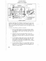
......- - - - CONTROL PARTS - - - - -
RATE
CONTROL
(~~~::;~~-CHARGE
RHEOSTAT
RELAY
" - - - - CO iii DENS ER
.,.~.
RATE METER
14 CONTROL SYSTml·
The electric self-start arid the ,remote control plants have a control cab,inet mount.ed at the generator end of' the plant. The wiring diagram in this book out lines the electrical. system of the entire plant. Reference should be made to this diagram whenever servicing the electrical system. SELF-STARTING
The self-start type '0£ control is used bas.1,cally on the D.G.· plants,. It consists'
primarily of a manually operated start switch, a charge relay and a charging' amin
eter. On the starting cycle, the current .!lows from the starting batteries through
the start switch to the generator Which acts as.a starting motor. Upon starting,
the switch is released and opened thereby breaking that circuit. ' AS' the plant gen
eriJ.tes current, a charging current flows through the charge relay and ammeterto
the sta;rting batteries.· This type of control orily permits starting at the plant
and stopping at either the plant ora,remote station.
REMOTE CONTROL
The remote type of control is used basically oh theA.C. plants. It consists prima:rily,.of a start-stop switch,start relay, charge'relay, charge ammeter, and a charge rheost')t plus a set of remote termirlal:s. This control perinit:;; ,?ta:r,ting, and stopping either at the plant or.at any remote point up to within 250 feet of the plant.r
.
. '
When the start· button is .pressed, i t closes ,the start relay., The contacts. of the relay close the starting circuit so that current from the starting batteries is fed to the generator whose exciter acts as a starting motor. Upon relea,se Qf .the start button, .the start
opens, a¢ opens the starting circuit. Upon ':reach": ,ing speed the exciter part
the generator becomes a.generator in itself., Curr
ent then flows into the charge relay rheostat and .ammeter and then to the starting .
batteries. The'rheostat controls thechargmng rate to the batteries.
.
PROPER ,sTARTING- The proper method
sta;rti!lj; any self-starting switch is not to
hold down continuously on the start ,button, but to intermittently close the start '
button for a period of about five secoilds, and.release for a second or two. Then
if the plant dbes not continUe to J:'Ul1, press the start button the. second or third
. time,. holding each time,. for about five seconds, until the plant conti'nues to,
operate.
.
,
STOPPING CYCLE - When. the Stop Button at the plant. or at a remote start-stop switch
is pressed, the ignition secondary circuit is grounded, therebr causing a failu:r'e
of ignition and stopping the engine.
.
.
SERVICrNG, -.It is not necessary to proviqe any regular servicing for the electrical
control system. However,. i t is advisable to inspect the Start Relay contactsocca-.
sionally to detennine whether they have"become burned or pitted in operation. If
this is found to be the case, the contact points should be cleaned carefully with
00 sandpaper.'
,
EMERGENCY STARTING
~
'-"
If.the startirig batteries do not have sufficient pow~to crank the engine, it may
be started by hand whether the ignition is battery or magneto. A hand crank is
provided and this is inserted into the cra~~shaft'at the front end of the engine.
Crank W:\.th a steady pull but do not, spin ,the crank.
15
f,lAm TEN AN CE
It is important that certain inspections and maintenance proce dures be made at definite periods' to keep the plant operating at a maximum level of efficiency. It is recommended that a service log be kept-. If operation is to be under abnormal conditions,
check those pages for correct maintenance. DAILY 1IIAINTENANCE
A daily check of the following points should become a matter of
routine.
Cooling liquid level.
Crankcase oil level.
l''uel supply - do not fill tank while plant is rurming.
4. -Inspection of operating gauges.
5. Keep the plant clean..
1.
2.
3.
WEEKLY
r~INTENANCE
Each week, or after every 50 hours of operation:
Oil - Check the oil level, adding whatever is necessary to bring
it to the IIfull" mark on the gauge. If necessary change oil.
1.
2.
3.
In cold weather - change every 50-60 hours.
In high temperatures - change every 100 hours.
In average temperatures - change every 200 hours.
When changing oil.run the plant until it is warm. Then drain and
refill with new oil. Do not drain when the engine is cold.
Fan Belt - There shOUld be 3/4" movement lIin n or !lout" from the
normal position. Adjl!st if necessary.
_Water - Check the water level arid add whatever is necessary. ,If
anti-freeze is used, add the correct proportion.
Fue.L - Check-the strainer on the fuel tank or pump. - Remove the
filter bOWl and screen and cleim both. Replace carefully. and
check for leaks.
Batteries - If used, check the water level. Add distilled water
to bring the level 3/811 above the top of the plates. Do not fill
to the top of the battery.
Check the charge condition with a hydrometer. If the reading is
below 1250 specific gravity, increase the charging rate. If above,
decrease the charging rate.
-Electrical Connections - Inspect all electrical connections.
sure- that they are tight and clean.
16
Be
\-;J. MAINTENANCE 'MONTHLY MAINTENANCE Each, month,
addition to
200 hours of operation, ,check the following points in
covered in the regular weekly servicing.
Lubrication Drain' the crankcase while the engine is warm. Replace the
plug and refill, with a quarts of new,' oil of the proper grade and viscosity.
Check the oil level in the fan hub and add oil if necessary.
the' filler plug is tight.
Be sure that
Plaee a drop of
throttle shaft
lubricating oi~on the following point~: carbUretor
Choke shaft bearings, and governor link joints.
Clean the air
oil of the
element, drain, the oil cup, imd refill with engine
as that used in the crankcase.
Ignition
the plant has magneto ignition, remove the cover from the
magneto and inspect the breaker points. Clean the points with a fine
stone. Readjustthe
to .014"
.016". .
'
On plants having battery ignition, remove the cover from the distributor,
clean the points, crank the engine until the po:i,nts open and adjust the
gap' to .019" - .021",
'
Remove the eovers ·from the spark plugs and the spark plugs from'the cylinder
heads. Remove the carbon from the electrodes and- porcelain. Reset the elec-'
trode gap at .025".
Generator - Inspect the commutator and collector rings and clean them if
dirty. Use a lint 'free cloth~The brushes should ride easily in the holders
and make good contact.
MONTHS INSPECTION
Every. six months go
of the weekly and 'monthly maintenance, and in
addition'remove the
plate and gasket from the rear of the generator.
Clean out all. the
grease from the generator ball bearing. RepaCK
the bearing with not'over'one tabl.espoontul of approved ball be~ing grease.
Never use ordinary. cup·grease. Repl.ace the gasket and, cover.
Check all.el.ectrical. connections including main l.ine wires, Check the brushes,
and replace' any worn to 5/8 11 • If the pl.ant has batteries, clean the contact
posts, tighten the connections, and cover them with petrol.eum jell.y•
. Check all nuts,' bolts, and, screws.' Vibration may loosen them impairing the
efficiency of the plant. Tighten any that are loose.
Check all hose connections. Repl.ace any hose that is weak or leaking.
Flush the radiator and engine ,thoroughly with clean water.'
.17
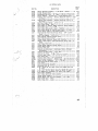
If 'trouble develops or the plant is not operating correctly,
, check the oil and fuel to be sure that the proper gra,des are 00
ing.used. Check the wiring installation. Refer to the chart
below and take steps to return the plant to good running condi
tion.
1. Plant will not start or is hard to start:
a.) Empty fuel tank.
b.) Poor grade of fuel used.
c.) Fuel line clogged or air locked.
d.) Spark plugs rouled, wrongly spaced, or cracked.
e. ) Ignition wire s loose.
.
f.) Ignition breaker ann sticking. g.) Stop button defective or shorted. h.• ) Oil too heavy due to drop in temperature. i.) Main line switch closed too heavy an electri cal load.
2. Plant starts but will not produce current:
a.) Open switch or line wiring.
b.) Fuses blown.
c.) Brushes stuck in holders and not touching
commutator.
d.) Brushe.s worn too low.
3•. Plant runs too hot: a.) Spark timing retarded. b.) Improper exhaust discharge. c.) Insufficient ventilation. d.) Radiator water level low. e.) Oil level low. f.) Oil too thin. g.) Carburetor mixture too rich. 4. Excessive oil consumption:
a.) Oil dirty ~ not changed often enough.
b.) Fuel mixture too rich causing excessive cyl
inder wear.
c. ) Piston ringf! stuck caused by improper lubrica
tion, overheating, or defective rings.
d.) Engine overheated due to poor ventilation.
Troubles peculiar to electric st1J.rt plants only:
1. Plant does not crank: a.) Discharged ,starting batteries. b.) Loose battery connections. c.} Open circuit in control box•. 2. Battery run down: a.) Open circuit in w~r~g. b. ) Charge relay not closing
c.) Voltage regulator relay not functioning pro
perly (cuts down charging rate before the
batteries are fully charged).
d.) Dead cell in battery.
e.) Lack of water. ,
18
3. Bat tery will not take charge: a.) Dead cell in battery. b. ) Internal short in battary.
c.) Open circuit in charging control winding.
d.) Battery plates sulphaten.
.
.------'--ACCESSORV SERVICE SHEET OIL LEIIEL SHOULD BE MAINTAINED
BETWEEN FULL AND LOW MARK.
NEllER ALLOW TO DROP BELOW
LOW MARK.
)
OW MARK
~T
•
SMfIl( GJlP
-AT
.ow-
DO
PRESS. STARTER
: BUTTOI\I J:ONTINUOllSLY
•W
AR'fING. ' . '
PR
J~Rlrl6JiNUJt~OR
ONDI!\.
19
ACCESSORY SERVICE This plant is equipped with a downdraft carburetor of the adjust
able jet type. It is one of the most- trouble free accessories on
. the plant, and should not be! tamperecl with. The only care and
attention ordinarily rE?quired is to clean the bowl each year to
remove accumulated sediment. However, c;~nges in the type of
fuel used, or in operating or climatic conditions may make read
justment necessary to keep the plant operating efficiently.
ZENITH TU3Y
Never make a final adjustment of the carburetor unless the
plant has been in. continuous Qperation for at least half an hour.
This will give t.he plant ample time to reach its normal- operat
ing .temperature.
.
If the plant operates unevenly under half load or full load, turn
the .main jet adjusting needle out for 4 or 5 turns. Then turn i t
in toward the carburetor bowl until the plant begins to lose speed
and power. Slowly opert it again until the plant rega;lns maximum
speed and power. This. will be the correct setting for efficient
economical operation, but sometillles it may be necessary to open
the adjustment up to 112 turn more to rid the plant of a hunting
condition where the engine will alternately gain and lose speed.
20
I;
~~~
Sl!:RVICB
If
the jet opening by 1/2 tUrn will not correct the
hunt,
sensitlvety of the governor must be decreased. A ser
ious hunt clin be drowned out by using a too ric h fuel mixture,
but economy of operation would be impossible, and possible dam
age to the pl~mt could result.
If the
unevenly under no loud or light loud, turn
the idle jet needle into the carburetor body until the plant
nearly stops. Then open it slowly to the point at which the en
gine runs the smoothest. Usually the setting for smooth and
economicl:tl operatiori. will be between 1/2 and 1/4 turns.
Continued irregular operation of the engine, hard starting, or
loss of power may indicate that the main jet of the carburetor
has become clogged. The fuel passage in this jet is very small
.and i f
material should succeed in getting tl;tru the screen
and filter bowl it can become lodged in this jet. It will then
be necessary to remove the float bowl cover of the carbu,'e.tor and
remove and clean the jet.
Be careful to Use a proper sized screwdriver whenever removinG
the main jet. Otherwise the brass might burr or distort and be
, worthless. Blow the jet out with air to clean it·, Never use a
wire to scrape the jet or the size !!light be changed. When ~e
placing the jet, be sure that the small fibre gasket is in place
beneath the hend of the jet.
The air cleaner is of the oil bath type mounted on the carburetor
intake. A flexible hose to the radiator allows clean air to be
tilrown :into the cf-lrburetor'. '£he cleaner is also connected to the
oiL filler tube' from which it draws all oil fumes back into the
\'Vhere they help to lubricate the valve stems and upper cyl
inder walls. The filter so operates that dirt and dust are de~
posited
in the-oil or accumulate on the screen from
which they drain into the oiL
The air cleaner should be serviced each time the oil is changed
in
crankcrlse. If dust. conditions are severe, or there is '
more than 1/2 11 of accumulated dirt in the oil cuP. service it
often. Remove the cleaner, pour out the old oil, and clean
out of the cup. Dip·the cleaner element in gasoline·or
to
the screen, and allow it to dry_ Fill the oil
clean oil'of the same grade as that used in the. crank
case, replace the cleaner, and tighten securely_
21
C'
ACCESSORY SERVICE AUTOMATIC CHOKE - The automatic choke consists or a thermostat
mounted,direct~ on the choke butterf~ shaft of the carburetor
and operated b.1 a nichrome heating element obtaining current
from the D.O. Generator winding. A valve is mounted on the choke
shaft and is off-center in the body. Vihenthe engine is cranked
and the air passes from the cleaner to the carburetor, the off
center position of the choke shaft allOWs the valve to be push
ed open slight~ b.1 the air stream working against the tension
created b.1 the thermostat on the shaft.
During the period while the engine is warming up to normal oper
ating temperatures,the small choke shaft knob or sheel, locat
ed at its outer end, will indicate the choke valve is oscillat
ing rapid~. As the engine reache5 normal temperature, the os
cillation will cease and the cooke va.lve will be open. With
the engine cold, turning the choke knob to the left, counter
clockwise, should result in the carburetor being complete~
choked.
Improper operation of the choke assembly will be indicated by
hard starting or irregular running during the warm-up periods.
A proper adjustment of the assembly can be made b.1 loosening
the small screw clamping the thermostat housing to the carbure
tor choke shaft boss and rotating it in a clockwise direction
(When looking at the choke knob), to decrease the air mixture,
or counter-c1ockwise (when looking at the choke k;nob), to in
crease ,the air mixture, to a position where it will give the
results indicated in the foregoing paragraphs. RIa-tighten the
clamp screw secure~ after the proper adjustment has been made.
~ ~
- The spark plugs used in, this plant are Champion
#M-6. Tl'\ey should be removed, cleaned, and gap set to.025" to
.030". A close inspection should be made to determine b.1 the
condition of the porcelain and spark electrodes if the plugs
should be replaced. As a rule, replacements shOUld be made after
1500 to 2000 hours of operation. The new plugs should be of the
Bame or a compara\lle make and type.
Visual Tests ,of spark plug operatioDl
~sulator is a light brown, operation,is satis
ractory.
2. If insulator is a dead white color~ plug is too hot
or mixture too lean.
3· If insulator has dull sticky deposit, plug is too cold
or ~ture too rich.
4· If insulator. has shiny black deposit, plug is too cold
or engine is pumping oil.,
5. If electrodes are burned, plug is too hot or poor fuel
has been used.
1. If the
\
I
A "hot" plug has a large area 'of the insulator exposed to the burning gases. A "cold" plug has a small area of the insulator exposed to the burning gases. DISTRIBUTOR - Plants using battery 'ignition have an Auto-Lite IGW
4115 distributor. This is gear driven by the camshaft. An oil
cup at the base is provided for lubrication. The distributor oil
ing and breaker points should be checked according to the 'service
page. Breaker point clearance is .025" to .030".
22.
ACCESSORY SERVICE
BAT'£ERY CARE AND Al'TENTION
With any plants using batteries, certain periodic care and atten
tion is necessary to increase the life and efficiency of the
batteries. Always follow the battery manufacturers reco~nenda
tions i f handy •. I f no't, use the following:
1. Keep the level of the electrolyte- about 1/4" to 3/8"
above the top of the plates.
2. Add only distilled water to the electrolyte.
3. Clean battery terminalS by using a solution of soda and
water. Apply a coating of petroleum jelly to prevent
corrosion.
4. \"/hen connecting batteries together, be sure that the
positive (+) post of one battery is connected to the.
negative (-) post of the other battery.
5 •. When connecting batteries to the plant, make certain
that a battery positive (+) post is connected to the
positive (+) terminal on the plant, and that a battery
negative (-) post is connected to the negative (-)
terminal of the plant. Reversing these connections
would discharge and ruin the batteries.
6. The average ampere' .charging rate should be approximate
ly one-twentieth (1/20) 'of the Ampere Hour Capacity of
the batteries. 'When the battery is discharged, it can
be charged faster, but with a nearly charged battery,
the rate should be reduced.
7. Remove the vent caps ".hile charging the batteries un
less the caps are marked otherwise.
.,
8. When charging batteries, make certain that the internal
temperature. of the batteries does not rise over 110 0 F.
If the temperature nears 1100 F., reduce the charging
rate.
9. Check the specific gravity of the batteries at regular
intervals with a good hydrometer. A discharged battery
will read from 115 0 to 1175; a half-charged battery from
1200 to 1225; and a fuliy charged battery from 1250 to
1280.
10. Keep the batteries in a fully charged condition. If
allowed to stand in a discharged state, the plates will
harden or sulphate, and the battery will not ta~e or
hold a charge.
11. If the batteries are in a discharged or near discharged
condition during cold weather, they may freeze and be
ruined. A discharged battery WiLl freeze at about 20°
above zero F., while a fully charged battery will not.
freeze until it gets about 800 below zero F:
12. Never add water to a battery during cold weather with
out letting it stand ina warm place long enough for
the water'to'become mixed with the electrolyte. Water
might freeze and crack the ,battery case if it W;:lS not,
given a chance to mix wi~ the electrolyte.
13. If batteries are received in a Semi-Dry condition from
the manufacturer, follow the instructions that accompany
them for putting into service.
23
ACCESSORY SERVICE
GOVERNOR
The purpose of the governor is to keep the generator voltage
within proper limits by holding the engine speed at a constant
rate. Failure of the governor to control the speed properly
would cause varying brilliancy of lights, or constantly chang
ing performance of accessories and appliances whenever ~he load
was increased or decreased.
Two types of governors are used on these plants. With one, the
operating mechanism is built as an integral part of the camshaft
timing gear and gearcase cover. The other is a commercial type
mounted to the top of thegearcase and driven by the camshaft
timing gear. Both types are as simple and troub~e free as any
mechanical unit can be, and neither type should need adjusting
or servicing unless the plant has been overhauled or the adjust
ment tall~peredwi tho
INTERNAL TYPE GOVERNOR
-I
I
I
I
I
I
\
\
.GQV. ARM
C.LAMP SC.REW
\
\
~
_ _ _ _ GOV. WEIGHT
'l\\----_
GOV. CUP
GOY. SHAFT & PADDLE
GOV. SHAFT PIVOT BALL
24 The governor arm is linked to the carburetor throttle arm. This, whenever the load changes and the speed tends to gain or drop, the governor mechanism immediately moves to offset the change in load and either opens or .closes the throttle valve to compensate for the change • .An .oval .headed thumb screw permits adjusting the tension of the
govenmor spring. Turning the screw in towards the body of the
governor arm bracket increases the tension on the spring;, the en
gine speed, and the generator voltage. Turning the screw out
decreases tension speed and voltage. Whenever adjustment has
been made and the voltage brought to the proper figure (not to
exceed 125 volts at no load), tighten the locknut against the
bracket.
.
.
If, for any reason,the governor arm has become loosened from the
governor shaft, it will be necessary to reset the arm. To do this,
loosen the governor arm. clamp screw, insert a screwdriver in the
slot in the governor shaft, and turn it to the right as far as
possible. Allow the governor spring to hold the throttle arm
against the. stop and retighten the clamp screw securely. This
will correctly set the governor arm and it will then be necessary
. to reset the adjustment on the spring tension to correct the
speed and voltage.
Four flyweights are so pivoted to the face of the camshaft gear
that as the engine speed increases, the weights tend to fly out
wards, forCing the governOr cup away from the gear. The cup bears
against a paddle welded to the governor shaft, rotating the shaft
and the governor arm attached to its end. Tension of the governor
spring against the governor arm resists this motion,and it is the
balance of force between the spring and the flyweights that' main
tains an even speed.
.
26
AeC~SSORY
SERVICE
GOVERNOR
BUMPER SPRING SCREW'
MPER SPRING SCREW
LOCK NUT
BUMPER SPRING
GOVERNOR
ASSEMBLY
A Pierce industrial type governor is bolted to the top of the
gearcase cover where it is driven by the camshaftt:i,ming eear.
There is no routine servicing required for this governor. In
fact, it should never need attention unless the engine has been
overhauled.
To adjust the
governor~
proceed as 'follows:
1. With the spring tension on the main governor spring
"A" adjust the length of the throttle control rod so
the carburetor lever clears the wide open stop by at
least 1/6411 •
2. Loosen the lock ,nut and screw bumper "B" out far
enough so it does not function. Then adjust the gov
ernor for the desired speed qy turning the adjusting
screw ne n •
3.
If the governor surges underload or port load condi
tions, screw the auxiliary adjusting screw liD" out a
few turns at a time until the.surgingstops. Keep
the screw"D" in as close as possible. without .surgiiig
to give close regulation.
4. If the governor surges at a no load speed, screw the
bumper "B"in far enough to eliminate the surge, and
then lock it. Do not screw "BII in far enough to in
crease the engine speed.
I
I'
26
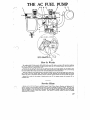
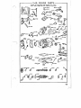
mE AC FUEL PUMP How It Works
By revolving shaft (G) ,the eccentric (H) will lift rocker arm (0) which i. pivoted'at (E) and which pull. the
pull rod (F) ,together with diaphragm (A) held between metal discs (B) downward against spring pressure (C)
thus creating a vacuum in pump chamber (M).
Fuel from the rear tank will enter at (J) i~to sediment bowl (K) and through strainer (L) and luction valve
(N) into pump chamber (M). On the return stroke, spring pressure (C) pushes diaphragm (A) upward forcing
fuel from chamber (M) through pressure valve (0) and opening (P) into the carburetor.
'When the carburetor bowl is filled the float in the Boat chamber will shut orr the inlet needle valve, thus creat~
ing a pressure in pump chamber (M). This pressure will hold diaphragm (A) downward against the spring
pressure (C) where it will remain inoperative until the carburetor requir~ further fuel and the needle valve operis.
Spring (S) is merely for the purpose of keeping rocker arm (0) in constant contact with eccentric (H) to
eliminate noise.
Service Hints
Service on the AC Fuel Pump is available through United Motors Service Branches and Authorized AC
Service Stations, who are prepareq. with parts and fixtures for repairing all types of pumps. There are some
serv~ce operations on this fuel pump that can, if necessary be done without referring to the service station and
these are tabulated on the reverse side of this sheet. In some instances trouble is attributed to the fuel pump
which in reelity is caused by 'some other condition. These should be carefully checked to avoid the needles.
replacement of fuel pumps.
27
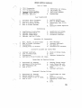
THE AC FUEL PUMP-Service Hints (con.'d)
LACK OF FUEL AT THE CARBURETOR
"
Check as follows: Cause
Remedy
Gasoline tank empty.
Leaky tubing or
connections
<.:unnecnons.
Bent 'or kinked tubing.
Glass bowl loose.
-.-~-
cork
. - - - - - - - - - - - - - + - - . - - ---_._. - - - - - - - -
Dirty screen.
the screen. Make certain that cork
is properly seated when reassembling.
Loose valve plug, Tighten valve plug securely, replacing· valve
plug gasket if necessary.
Dirty or warped valves.
Remove valve plug and valves. Wash valves in
kerosene. If damaged or warped. replace them.
Examine valve seat to make certain there are
no irregularities whiCh prevent proper seating
of valves. Place valve in valve chamber. Re
assemble valve plug and spring. making certain
that spring· is around the lower stem of the
valve plug properly. Use new gasket under valve
plug if necessary.
.
FUEL LEAKAGE THROUGH VENT HOLE IN BODY
Check as follows:
Cause I
Worn or
Remedy
diaphragm.
Replace diaphragm.
I
I
Check as follows:
I
I
Cause·
Remedy
Loose cover screws,
screws alternately and securely.
and outlet pipe connections.
I
I
FLOODING OF CARBURETOR
Check ,as follows:
Cause
, Carburetor needle
IMPORTANT: "Vhen the above. remedies do not correct the condition,. replace.with a new
fuel pump sending the old fuel pump to the, nearest AC service. station for repairs.
28
'
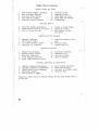
~~GINE SlRVICE DIAGNOSIS
Lack of Power
1.
2.
Poor Compression
Poor Carburetion.
5.
J.4. iiHVfOf)8f
Yal ve Sea ting,
Defective Ignition.
6.
7.
Restricted Air Intake.
Low Octane }uel.
Restricted Exhaust.
i1.
Overhea.ting.
5.
Leaking Gaskets.
Worn or Broken Rings.
Excessively Worn Cylin
ders.
Excessive Carbon Deposits.
Poor Compression
1.
2.
3.
4.
Incorrect Valve Clearance.
Incorrect Valve Timing.
Worn or sticking Valves.
Weak or BroKen Springs.
6.
7.
8.
Overheating
1.
2.
3.
4~
Insufficient Ventilation.
Improper Lubrication.
Improper Carburetion.
Improper Ignition Timing. 5.
6.
7.
Restricted Air Intake.
Restricted Exhaust.
Electrical Overload. Excessive Oil Consumption
1.
2.
3.
4.
Worn, Broken, or Stuck ttings.
Worn or Scared Cylinders.
Overheating.
Leaking Seals or Gaskets.
5.
6.
7.
B.
Worn Bearings.
Improper Lubricant.
Too much Oil.
Excessive Oil Pressure.
Excessive Cylinder and Piston Wear
1-
2.
3.
4.
Improper Lubricant.
5.
Lack of Lubrication.
6.
Overheating.
7.
Improperly Fitted Pistons and Rings.
stuck or Broken Rings.
Dirt.
Improper Carburetion.
Connecting Rod Bearli1g Failure
1-
2.
3.
4.
Restricted uil Passage.
Improperly Fitted Bearing.
Bent Connecting Hod.
Lack of Oil.
5.
6.
7.
8.
Bearing J ourrtal Hough.
Loose Connecting liod.
Insufficient Oil Pres,.,
sure.
Improper Lubricant.
Crankshaft.Bea.ring Failure
1- Restricted Oil Passage.
2. ' Bearing Sprung or ,Loose.
3.
4.
Journal Rough or Out of' Hound.
Lack of Oil;
.
8.
Insufficient Oil Pres
sure.
Improper Lubricant.
Improperly Fitted Bear
ing.
Dirt.
Burned Valves and Seats
1. Insufficient 'fappet Clearance.
2. ,iieak or Broken Springs ~
J. Incorrect Valve Timing.
4. Late Ignition Timing.
5. Excessive Carbon Deposits
6. Sticking Valves.
7. Improper Valves.
8. Valve Head '1'00 'rhino
9. Valve Seat Too Narrow.
10. Overheating.
Sticking Valves
1.
2.
Incorrect Tappet Adjustment.
Insufficient Clearance in Guide.
3. Weak or Broken
4. Scared or Dirty Stems.
5. ~cessive Carbon.
6. Gum Content of ~'uel
'roo Great.
Insufficient Oil Pressure
1.
2.
3.
4.
Improper Lubricant.
Kelief Valve Stuck. Oil Intake Screen Clogged.
~cessive Oil Dilution.
5. Excessive Bearing Clear
ance.
6. Worn Oil Pump.
7. Insufficient Oil.
Defective Ignition
1.
2.
3.
4..
5.
Breaker Arm Sticking.
Breaker Points Pitted.
Defective Condenser.
Point Setting Incorrect.
Spark Plugs ]'ouled or, Dirty.
6. Stop Wire Grounded.
7. Defective Coil.
8. Low Power Source.
9. Leak in System.
Poppine, Spitting, or Spark l(nock
l~
2.
3.
4.
5.
Improper Ignition Adjustment.
Improper Carburetor Adjustment.
Insufficient Valve Clearance.
Excessive Carbon.
Worn Pistons or Rings.
6. Valve Timing Incorrect.
7. Weak Valve Springs.
$. Hot spot in Cylinder Head.
9. Inferior Fuel.
Pinging or Spark Knock is usually caused by the spark being advanc-
,ed too far.
,
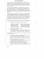
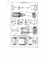
CYLINDER AND VALVE SERVICE SHEET ~
..
r
VALVES
r
fI .. VALVE SPftlNGS
l$
VALVE
SPRING
e_
8
7
WASHERS
•
"....
VALVE
'!>P~ING
~LOCK5
CYLINDER
HU
AROPLU6
COMPRE'S51~N
RINGS
~...
~
<0
~
Q • PISTON PIN LOCK RING ~.
!V-"~
PISTON PIN
AOo./l/ST CLeARANce WITH F/5
TON ON TOF F05fTION or THE
COMPReSSION '5TI?OKE.S"TH
VAl.VES MUST BE CLO$£D.
.
/SCTINTAKII YALVe - .008
SCT£XHAUSTVALVII-.OJO
VALVE CLEA~ANCE CHECK
.31 YEARLY ENGINE SERVICING
Each y.ear, if the plant is used under normal conditions the
accumulated hours of operation will total 2500 or more. After
every 2500 to 3000 hours, the engine should be given a thorough
checKing over,the valves should be 'ground, the caroon removed~
and the pi~tons, piston rings, valves, bearings, etc. should be
carefully checked.
Valve grinding, accompanied ~ a thorough cleaning of canbon, is one of the most frequently reQu:i,red service operations in a . modern gasoline engine. As the. plant, during the years service~ has ordinarily been used to an extent comparable to 4000 to
5000 niiles in an automobile, the lncreased efficiency and savingS
in operating costs will more than make up for the time and labor
invested.
Inspection plates are provided on both sides of the engine crank
case •. By removing these plates and inserting a trouble lamp in
to the crankcase, practically all of the wearing parts can be
inspected ~ sight or by feel'to determine the extent of the ser
vicing needed. By making this inspection first, and estimating
the extent of repairs beforehand, necessary parts and gaskets
can be ordered from the factory so the plant will' not be out. of
operation for more time than the actual servicing requires.
We recomlnend that the following parts, plus any additional parts
which inspection has inaicated are needed, should be on hand:
1. A complete set of engine gaskets, to include:
2
2
2
2
2
cylinder head gaskets
cylinder base gaskets
water inlet gaskets
water outlet gaskets
inspection plate gaskets
2
2
2
1
1
cylinder head cap gaskets
intake manifold gaskets
exhaust manifold gaskets
carburetor flange gasket
valve tappet cover. gaSket
2. A complete set of radiator hoses.
3. A set of piston rings.
4. An assortment of valves, valve guides, springs, locks,
etc. suffi.cient to replace any warped or burned valves
broken springs, or worn guides that may be discovered.
To disassemble the engine for valve or piston service, follow the
autlined procedure •.
,
J...
. 2.
3. 4·
5. 6. 7. 8. 32
Disconnect all main lines or batteries from the plant.
Drain the water from the cooling system •
Remove the radiator hoses, and the water inlets and out
lets. If there is a temperature guage, disconnect. it
first.
If an external governor is used, remove th~ 011. line be
tween the crankcase and the governor.
Disconnect the governor arm from the carburetor, and re-.
move the govern~r if an external type.
Remove the 'fuel line leading to the carburetor.
Disconnect the air cleaner from the breather tube and
from the air inlet ,hose. Hemove the cle~mer.
Remove the carburetor; choke, and intake manifold asselll
bly.
~
'~.'
RADIATOR WATER INLET
CYLINDER WATER OUTLET--{-'_-~
'
~ "-',,@
BELTADJUSTlN~SlUD~1I
"'--ri
II
II I I '
fAN SUPPORT ARM
fAN
fATN BELT ADJUSTING
S UD i:OCK NUT
II
II
fAN BEll,
fAN HUB OlL HIlLE
fAN
I I
II
II
'I~
1
I ,"
/1
:
SPARK
_---00(,
CYLINDER HEl'O----
ClLlND,fR',HEAD ,.",..',-
fRONT
CAMS~Afl
TIMI~G
I
I. _' !
~I
BEARING
!..!.!----"-U,NSHAr1
I
1
SPARK P l U ' G - - - - - - - , . -
'CYLINDER HtAD NUT5
AIR
GEAR
TI"'NG~
GOVERNORflV~~T~
AIUj~~ ""i."
GOVERNOR ARM
':
GOVERNOR
SHAfT & PADDLE
""
0
GOVEROO!! CUP STUO
THRUST ,BEARING
RADIATOR eASE
01;'
I
---yf
~
\
L~"
L
GEARCASE OIL SEAL
GEAReASE RADIATOR DRAIN COCK
-.;',
~::. N~~,
•
CRANKSHAFT TiMING GEAR
EXHAUST OUTL~T (I-V4"P,PE)
DRAIN PLUG
_ _==--_MDIJNTINV RUBBER
,
' '"
0
MOOEL
V~4~
ELECTRIC PLANTS
AIR CLEAnER
1!IIIIi®;~:::--- OIL FILLER CAP
DIWENSIOIiS
lENUHT OYfRAll
WIDTH OI'[RAU.
HEI GHT ovt RAI,L
4) Vl·
i! I"
34"
MOO~rl~FDrLfa~~iR5
GENERATOR FRAUE
(
YEARLY
~
SERVICING
9. Remove the valve,tappet cover and oil filler tube.
10. Disconnect the ignition wires and remove the spark plugs.
11.' Remove the cylinder head nuts and lift the cylinder heads from
the blocks. If they stick, tap the head sharply with a lead
hammer to loosen. Never attempt to pry them off with a bar or
screwdriver.
12. Remove the cylinders blocks from the crankcase. Be careful not to let the pistons drop on the edges of the crankcase and become damaged.' Inspect the pistons anq piston rings carefully. Remove the rings, keeping
them in order so they can be replaced in the same grooves and positions.
Scrape any carbon from the gr.ooves in the oil control piston rings and
'from the grooves and oil return holes in the pistons. Clean the carbon
from the piston heads. If the rings have considerable tension, are bright
and shiny showing a good fit to'the cylinder walls, are not worn exces
sively, and £it snugly in the piston grooves, replace them in the grooves
from which they were taken.
If the rings show signs of wear, they should be replace~ with new ones.
Fit each ring individually'to'the cylinder for which it is intended. If
necessary, file the ends of the rings slightly so there will be an end
gap of approximately .010" when the ring is in position in the cylinder.
After the pistons and rings have been cleaned or replaced, wrap a clean
rag or piece of cardboard around the pistons to keep them from being
damaged.
~, Grinding - Compress the valve springs and remove the valve locks.
i
,!
Wi th the locks removed, the washe'rs, valve springs, and valves Can be
lifted out of ,the block. Inspect the condition of the valves. If the
stems are worn or bent, replace with new ones. Pitted valve faces can
be refaced on a valva face grinder if the valve is otherwise in good con
dition. However, never use a re-faced valve tha.t has a thin' edge.
Va.lves With thin ~dged heads will warp or burn after a short time. When
refacing Valves, be sure to get a true ,450 angle to the faces.
Clean the valve heads, stems and guides of all dirt and carbon. If the
valve guides are badly worn, they can be punched out and replaced with
new ones. :Check the condition of the valve seats. .The exhaust valve
seats can be removed and replaced if too badly burned Or cracked. Usu
aliy, a pitted valve seat can be restored to good condition by using a
reamer designed for 'that purpose. Scrape all carbon from around the
valve seats and'the top of the cylinders.
'I
Put a thin coating of a medium grade of valve grinding compound on the
face of valve. Slip a thin coil spring over the valve stem, and insert
the valve stem in, the guide. Using a valve grinding tool, rotate the
valve back and forth against the seat. The spring prevents too much
pressure and assures easy removal.
33 YEARLY ENGINE SERVICING
After several cycles back and forth, lift the valve and turn it so d.ifferent surfaces of the valve face and seat will be touch ing. hepeat the rotating process until a bright silvery band, the width of the valve seat, extends all around the valve face, and the valve seat ShOl'lS a high polish. Add new compound when
. ever it loses its cutting properties.
Remove the valve anei wipe all truces of the grinding compound from the valve and valve seat. Using a soft pencil, draw marks a.cross the valve face. Heinsert the valve, and rotate it against the seat. If the pencil marks are erased, a gas-tight fit has been secured, but if not, repeat the. grinding process until each valve will pass this test. After all the valves have been ground to their individual seats,
and all traces of carbon scraped from the blocks, replace the
valves, valve springs, washers, and locks. Install the cylin~
der blocks onto the crankcase., compressing each piston ring care
fully to prevent breakage. Oil the .pistons and piston rings be
fore sliding then into the cylinder walls, and be sure to use
new cylinder base gaskets.
Clean the carbon from the cylinder heads. Using new gaskets thru
out, replace the cylinder heads and draw them tight. When tight
ening the cylinder head nuts, tighten them evenly and never drav.r
one up tight until the others are nearly so. Tighten the center
one first and then tighten the others. 'rhis a~sures a bet'~er
seal, and prevents the possibility of the head warpine.
19:P"pet Adjustment
Loosen the cap screws locking the tappet
levers to their bearings, and push the levers as far into the
crankcase as possible. With each piston at top dead center on
the compression stroke while making the adjustment, insert an
.008 n feeler gauge between the camshaft and the face of the cam
follower lever •. Pull the lever upward until theguage is squeez
ed lightly between cam and the lever face; .and 'then tighten the
cap screw securely.
.
CARBUHETOR - Remove the carburetor and disassemble it to clean
out the jets and remove any sediment from the bowl. See the
carburetor accessory page. Replace all ,gaskets including the
o;ne between the in.take manifold and the carburetor. Then replace
it and oil the moving parts Buch as the throttle and choke arms. .
COOLING - The cooling system should be thoroughly flushed and i f
available a cleaning agent should be used for the radiator. Ins
pect the condition of the hoses and if necessary replace them.
Check the tension of the fan belt and see that the hub is well
lupricated.
GOVERNOR ADJUSl'Ml:NT - See the Accessory Service Section for the operation of the governor before making any adjustments. 'rhe proPer operation is essential for corr.ect engine speed andgen erator output. 34
YEARLY ENGINE SERVICING RUNNING - When a reconditioned plant is first started, little or no
load should be connected during the first several hours of operation.
This will allow th~ new and reconditioned parts to wear in without ex
cess1vewear and prolong their life.
It is advisable after such a run-in period to go over each of the nuts
and bolts, especially those holding the cylinder and cylinder head and
retighten them. Also remove the valve tappet cover and recheck the
clearances, readjust them if necessary.
THE FOLLOWING IS A TABLE OF CLF..ARANCES FOR BEARINGS AND OTHER PARTS OF
THE ENGINE, AND SUGGESTED METHODS FOR CHECKING THEM.
Valva
Valve
Valve
Valve
Tappet Clearance (Intake)
Tappet Clearance (Exhaust)
Seat Width
(All)
Stem Clearance in Guide
(Intake)
Valve Stem Clear~nce in Guide
.
i,·. (Exhaust)
Crankshaft Main Bearings (Dia.)
Crp,.nkshaft End Play·
Connecting Rod Bearing (Dia.)
Connecting Rod Bearing (End Play)
Timing Gear Backlash
Piston - Cylinder Clearance
Piston Pin in Piston
Piston Pin in Rod
Cl'lffishaft Main Bearings
PistQn Ring Gap in Cylinder
MINUMUM MAXIMUM TESTING DEVICES
.003" '.010" 'rhickness aauge
.01211 Thickness Gauge
•OlD"
(3/64") (1/16 11 )
Go-NQ Go Gll.uge
.002"
.00)'"
.0025"
.0015"
,015"
.0015"
.003" Go-No Go Gauge
.0025" ~licrometer .020" Thickness Gauge .0025" Thickness Gauge Paper or Hand Fit .00)"
Thickness Gauge HAND PUSH FIT .0002
.000)" Drags·when cold .002
.0025 Thickness Gauge .OOS
.015
Thickness Gauge .001."
.006"
.oo~n
.005"
.005"
35
MAJOR EN GINE OVERHAUL
After IDng periDds Df time, usually frDm Dne to. five years Dr mDre Df hard DperatiDn, a ,cDmplete overhauling o.f the engine arid generator will beco.me necessary. Ho.wever, a ·majo.r o.ver
hauling should nDt be attempted until a crankcase inspection has been made to. determine whether o.r nDt it is needed. No. perso.n unfamiliar with the aperation Df moderri internal com..:.
bustian engines shDuld attempt to averhaul this plant. The
disassembly Df the engine and generatDr will fallow a natural
sequence, and the sectiDns an "Yearly 1'ngine Servicing" and
an flGeneratDr Service" shDuld be thDroughly studied befDre start
ing the wDrk. These twO. sectiDns cover the disassembly Df the
generatar in its entirety and o.f the engine up to. a certain pDint.
Remove the radiator f'rom the engine. With this remaved, the' crankcase can be unbolted and remaved from the Dil base. The gearcase is also eXPo.seq and can, be remo.ved to. service the gDV
ernDr o.r the timing gears. Examine each part as it is remo.ved, and decide which IlUl.st be replaced, which need adjustment, and which'just need cleaning. Replace any parts Df which there is any do.ubt, as it is po.o.r eco.no.my to. use a part wo.rn to. an extent that replacement wDuld be necessary befo.re ano.ther servicing shDuld be due. Replace. all worn o.r scared pistons, pins, and rings. The cylin ,ders can b,e ho.ned or bo.red to' an o.versize diameter and larg.er' - pisto.ns, can be furnished by the facto.ry. Have this wo.rk dDne
in a co.mpetant, pro.perly equipped Sho.p, o.r if this is not practi
cal, new cylinder blo.cks, using standard sbed parts can be o.b
tained.New co.nnecting ro.d bearing inserts can be installed to.
resto.re pro.per bearing clearance unless the bearing jo.urnal 8nr
faceR have beco.me scared o.r, rough.
'l'11emain engine bearings al.'e 'not adjustable ,but sho.uld seldom.
If necessary, the old bearings c,an be punched o.ut o.f the case. and new bearings can be set in. Be sure that the o.il groo.ve in the babbited bearings heads in a directio.n o.ppo.site to. thero.tatio.n o.f the shaft. The bearings must then be line reamed to. the pro.per size. ,if evert need replacement.
Two. o.il seals are used. Bo.th are of leather and sheet metal co.nstructio.n with the rear main bearing o.il seal being larger, and pressed into. . the rear main bearing. '£he front o.il seal is pressed into. the gearcase cover. Bo.th seals, must be replaced whenever the engine is overhauled, and at any o.thertime when they fail to opera:te properly and alloW oil to be thro.wn fro.m the crankcase. Use care when installing new .seals no.t to. dam
'age the lip of the seals o.n the keywayso.n the crankshaft. G:rease the shaft carefully before slipping the seal over the shaft. Tap the seals into place,' and shellac the surface after the seal has been installed. 36
MAJOR ENGINE OVERHAUL
ThE; camshaft is driven by a helical cut steel gear keyed to the
crankshaft and retained by a
hexagon nut and washer. 'fhis
meshes vfith a cast iron gear~eyecl to the cw,]shaft and helci
in place by a lock, ring. Ordinarily, one,gear should not be re
placed unless the other is alBo.
Befol'e installing Ii new crankshaft gear, the timing marks on .the
two gears should be lined up to provide correct timing of the
camshaft.' Then press or tap the gear in place and tighten it se
curely. The mesh between the gears should be checked carefully.
A piece of newspaper should pass between the teeth of the gears
without binding-. A piece of heavy wrapping paper should not
pass between the 'teeth. This test indicates a clearance or baCK
lash of from • 003 11 to .005 II •
It will be necessary to reset the governor after a major overhaul
ing. ::lee the section on governor adjustment under "llc cessory
Service ll for complete details on adjustnient.
37
,-------.-- FLYWHEEL PULLER ASSEMBLY-------. THE REAR ENGINE VIEW SKETCH ABOVE ILLUSTRATES THE OPERATION Of THE FLYWHEEL PULLER IN REMOVING THE FLYWHEEL FROM THE CRANKSHAFT TAPER. ,THE OUTER BOLTS OF THE PULLER ARE TURNED INTO THE
FLYWHEEL HUB. A STEEL BLOCK. IS THEN PLACED OVER THE
CRANKSHAFT END TO PROT~CT IT FROM BEING DAMAGED BY
THE CENTER BOLT OF THE PULLE~:-THE CENTER BOLT Of
THE PULLER IS THEN DRAWN DEAD TIGHT AGAINST THE
STEEL BLOCK AND RAPPED SHARPLY WITH A HAMMER AS
SHOWN IN SKETCH. THIS WILL LOOSEN THEFLy'M-tEEL FOR
REMOVAL.
38 -
GENERATOR SERVICE The interior and exteri.or surfaces .of the generat.or must be Kept
clean and free fr.om metal dust, dirt, .oil, and water. A stream
.of compressed air directed thru openings in the generat.or frame
after the cover has been removed, is the most satisfactory method
of removing .ordinary accumulations .of dirt and dust. Be sure
that the air stream is free from oil or water, or the cenditien
will be made worse.
If the interior surfaces of the generator are oily, the. generator
have to be disassembled and the parts thoreughly cleaned
with a solvent such as gas.oline, benzine, or carb.on tetrac'hloride.
An oily condition may be jm indication that the rear main bearing
oil seal is leaking and needs replacing. Checl< the condition of
this seal and replace it if necessary while the generator is se
parated from the engine.
The following chart has been prepared to assist in locating both
the most common troubles Rnd their causes as associated with
91ectric generat.ors.
~==~~~
1.
....
')
J.
HEATING
Overloading.
Shorted Coil .or Coils.
Grounded.Armature .or Commutator.
4.
5.
6.
Peer Cerr@utatien.
Unequal Air Gap.
Heversed Field Ceil
Note: Any of these conditions cause a large circulat
ing current in the windings to the cOfJ1r,mtator, the brushes,
and the brush connections, and cause an artificial over
loading of the armature.
1.
2.
Operating Speed Too High with a Hesultant High Output Voltage.•
A Partial Short Circuit of One Coil
POOR====::...
1.
2.
3.
4.
5.
Brushes Unevenly Set.
Brushes Not Fitted.
Brushes Binding.
Brush Spacing Unequal.
Worn Brushes.
6.
7.
8.
9.
Brush Pressure Insufficient.
Brush Pressure Uneven.
Wrong Type of Brushes.
Commutater Bars 100se..
High·fAica.
FAILURE
1.
2.
}'.
Plant Speed Below Normal.
Heversed Field Winding.
Reversed Shunt Field.
4. Brush Location Wrong.
5. Zxternal Short Circuit.
6.
Open Circuit in Shunt Field.
39
ALTERNATING CURRENT GENERATOR· PSSY '0'
.
o
•
-CAUTION
ceANKSHAI"T TAPeR MUST
BE CLEAN AND FREE OF'
MARKS TO OBTAIN A
BELL HOUS1I-JG
BAND
TRUE RI.I#III#G AliMA
TUllE.
LL HOUSI Go
@eY
ORIVE HUB OISC. ORIVE HUB m.,,, "".
~'""
BEARING COVER
CARE OF COMMUTATOR
CASTING
1
AND. BRUSHES I
I
FOR T£STlNG GROUNLiS,
OPeNS SHQRTS ETC.
I.ISE· <3-4 CANDLEPOWl:R
BlIL8S USe 12 VOLT BULBS .WITI1 12 VOLT BATTERY.
USE 6 VOLT /'jULBS
WltH·6 VOLT BATTERY.
USt: 00 .SANOPAPeR
NC.V£R USE EMERY
OR EMeRY PAP£'R_
REPLACE ANY BRUSH
WORN TO ;u,." OR . LEJi S
G&~ERATOR
SERVICE
GENERAL
The generator consist of two assemblies; the armature,
,which is the rotating' part of the generator, and the frame assem
bly,1I'hich is the stationary part of the generator. The frame
is a steel ring with two or four field coils and pole shoes bolt
ed to the inside. The brush
assembly, 10,cated in the genera
tor end bell, is also a
frame assembly ,and it is not
necessary to separate these when removing the generator frorathe
engine.
Ordinarily, most generator troubles can be checked and corrected without, disassemb15.ngthe generator, by removinff the band around the generator end belL When this band has been removed,there is ample room for replacin'g the brushes or brush springs, or for checking the various parts of the generator. ,
~
The most common reason for a generator failing to produce cur rent is Ci,n external short on the main line, or :\-n the control or outlet box. Disconnect all wires leading fr.ofi1 the generator, am~l run a test lamp across the output of the generator while it , is running. If, the test lamp lights, the external circuit must
be checked for a short circuit or a 100S6 connection, but
it
fails to light, the generator is at fault ::md :steps must betak
en to locate and correct the trouble.
Check the brushes to make sure that they ride freely in their holders c,nd that. there is sufficient spring tension on all the brushes. Check the wires leading from the bnu3hes. If every thing appears to be normal, disconnect all batteries or main line wires from the plant. Raise the brushes in their ,holders until the springs slip dovm the sides of the brushes and 'keep them from rnaking contact with the armature. Disconnect the D.C. field '.'lire, and proceed as outlined in the following paragraphs, using the tests which apply to the generator to be tested. 1111 Onan generators produce direct current, but only those rated as alternatine current generators need be given the additional tests for that type of generator. 7-===~ FIEJ.Dfi FQn OPElIl CIRCUnS
Connect one end of a test
to one field wire and the other end to the 'other field wire. The testiamp should li£ht, i f the field coil wir.... ing has not been broken. If it fails to light", the winding or circuit is 0PEinanda new field coil set must be installect. However, if the break is ina wire connecting two coils, th" connection can be resoldered, ami the plant will again operate. TESTING FIELDS 1'OR GROUNDQ - Connect one end of the test ~mp
wire to one field wire (;'11d the other end to a clean surface on
the generator frame. I f the lamp lights, a field coil is ground
ed? and the field 'coils, must either be replaced or repaired.
Temperature chanGes cause metal to e:;~pand or contract. Varying
degrees of expansion between the iron in the frame and pole pieces'
and the copper in the wiring of the field coils can causeachaf-,
ingwhichmay, over a long period of time, wear thru the insula
tion protecting ~he field coils and allow the wires to touch the
frame. The electric current which should go to magnetize the pole
pieces will be side':"tracked,no magnetic field will be set up, ,
',and consequentlj" no current w:iIlbe produced.
41
_GEN_EJ1~1gB
=::;;..;:.=
The role
can be unbolted from the frame allo'Wine, the ree:
lilovalof
field coils. If the wires are not rlam&'f,&cJ, a
of tape cI,;.n be .placed over the worn spot, and the gr01mded
coils made serviceable again.
TESTING FOR, A
ed fit-lIn coil
J"IE1..D
A shorted or
short
the
amount of ' resistance in each coiL 1Is the amount of resistance
should be practically the same in each coii; if .one coil shows
less 'than the others, i t isa good indication that that coil is
shorted..
by n meter which
If there are no instruments handy for ma.king this
a fairly
accurate check can be made when the symptoms are first noticed
by feeling the temperature of the coils before
the pl
ant. If one coil is shorted, it wIll run .much cooler than the
others, and by feeling the generator frame where the pole shoes
are bolted to it, a shorted coil CHn be located. A shorted
coil must be replaced.
=== 'l'Ht
OF THEARi;JiATURE FOB QBOUNDS - If one
is placed on a clean surface of the ar
mature shaft, the lamp should not lieht when the other end is
touched to the commutator. If the lamp lights, the commutator
or D.C. windings of the armature are grounded and the armature
will have to 'be replaced.
D. C.
TESTINj} THJ:: D.C_,- FINDING OF' 'fHE =~:.:::=:::=.. _FO_R _OP_.f£}i
test lamp should light when
one commutator bar, and the
other bars. If it fails to
wire leading to that bar is
placed.
=='-=7""
A
one
wire is
to
other end touched to each of the
light when touched to any bar, the
open and the armature must be re
~== A.C.
ARMATURE l!'OR
CIRCUITS OR GROUND§
WINDING OF
one end of a test
wire on the
or insulated col
lectbr·ring, and the other end on the inner collector ring. if.
the windings are .in good condltion, the lamp Vlrill
if it
fails to light, the circuit is 9pen, and the annature must be re
placed.
Place one end of the test lamp wire on the armature shaft. Touch
the other end to each of the collector rings. If the lamp £ights,
the winding is grounded, and the armature must be replaced. .
Note: Only a competant, well trained', armature repair ser
vice man is qual'ified to repair an armature that is either
open or grounded. The. armature must be 'completely rewound
to correct either of these conditions, and no person with
out
training should ever attempt to do -this work.
=== CONDEN.8ERS
condensers are mounted inside
frame. If one
these condensers should becomEi ~"',__ 4'~"
no current.Vlould be generated. Disconnect the condenser leads
and try the plant with the condensers disconnected.•. If .the plant
operates satisfactorily, check each condenser, and replace the
one that is faulty. It is necessary to use condensers .in the
g€merator to supress radio interference.
42
GENEHATOR SEHVICE Gl:;NEJ:tA'l'OH.
If the foregoing tetlt8 have shown that
tbe field coils or. armature need servicing or replacing, the
generator'must be removed from the engine and the armature" dis:..
connected from the engine crankshaft. If there is a fuel tank
mounted on the generator, it must be removed. Likewise, any con-'
trol box installation mounted on the generator should be taken
off and set aside. On plants which have a starting sheave at
the rear of the generator, loosen the
screw and pull it off
the armature shaft, taking care not to lose the key "Thich locks
it to the shaft.
Ri.fiJOViNGTH.r.; FRAME
TH~ bNGINB
All generators are carried
on a turne,d diameter at the rear of the crankcase. After a.ny
accessories which were mounted on the generator have been remov
ed, the frame itself can be separated from the engine by loosen
ing and removing the bolts which hold it in place and drawing it
off over the armature. If i t should stick when unbolted, a well,
directed blow with a hammer and punch at the inner rim will loos
en the frame from the adapter ring.
Use great care 'when drawing the frame over the armature. Never
allow the frame to touch or rest on the armature, as the weight
of the frame can bend or distort the armature shaft enough to
make it unserviceable.
BRUSH RIG - It is not neC!;lssary to remOlTe the brush-rig assembly
from the generator end bell' when disassembling the generator. '
If it should have been removed accidentally, or for servicing,
lineup the mark on the rig with the indicator point on the
frame when reinstalling it. Unless the brush rig is in the pro
per position, excessive arcing of the brushes, heating of the
generator armature and field windings, and low volta~e produc:..
tion will result.
POLE SHOES - The pole shoes are made up of laminations of spec
ial electrical steel stacked and riveted together and bolted to
the generator frame. They are to be removed only in order to
remoVe the field coils. Wheri replacing pole snoes, b~ very care
ful that all surfaces are clean. An hccurateclearance must be
mainta;ined between the pole shoes (when assembled in the genera
tor frame) and the revolving armature. Any dirt between the pole
shoe and the generator frame would change this clearance and
possibly cause damage to the armature~ Use lock washers with
the bolts, and be sure that they are tightened securely.
REMOVING ARMATURE FROI~ BNGINE - The armature is coupled to the
crankshaft, and supported at the forward end, by the rear main
crankshaft bearing. On smaller generators, the armature. shaft
is tapered and fits into a tapered surface in the crankshaft.
The armature shaft is hollow, and a drawbolt runS from the crank
shaft toa nut at the outboard end 6f' the armature shaft which
cla.mps the two'securely together. Loosen this nut and back it
'off ,until the nut is even with the end of the bolt and then
strike it a sharp blow. This will loosen the armature shaft,
and it can be drawn 9ff over the stuc;l when the nut is remOlTed.
43
GENERATOR SERVICE On medium sized generators, a more flex-ible type of coupling is
used which will allow for slight misalignment between the engine
and the generator. In this arrangement, a flyYlheel is tapered
ana. keyed to the crankshaft. A machined. surface at the end of'
,the armature shaft fits against a similar surface on the flywheel, ,
and dowel pins lock them together. A drawboltclamps the entire
assembly together in a manner similar to the arrangeme,nt used on
the smaller generators.
Loosening and removing the nut at the end
the armature shaft
permits withdrawal of the armature. If it is desired to remove
the flywheel to check the rear main engine bearing oil seal,
strike the flywheel a sharp blow at the edge to loosen it, and
pull it off.
On larger sized generators the armature is bolted to the genera
tor blower. The blower in turn is bo.lted toa separate -flywheel.
Remove the four nuts just inside theriffi of the blower. Support
the, armature while these are being loosened, and when the last
one is off, slide the a,rmature over the studs and set it to one
side where it cannot roll or become damaged.
ARMATURE
The armature is made of of a stack of perforated disks
or laminations pressed onto a shaft. Wire is wound on this stack,
and the ends are connected to copper bars or rings. On direct
current generators, there are only the bars, called a commutator,
,from whioh direc,t current is drawn. On alternating current gen
erators, there are both the bars (commutator) which supply direct
current for exciting the alternator field coils, and rings, known
as collector rings, which supply alternating current. Separate
windings are used for the bars and rings, but both windings are
wound on the same shaft.
Always handle the armature carefully and do not allow it to roll
around. It can be easily damaged by rough handling.
The commutator on the armature is probably the most frequent
source of generator trouble. If it is dirty from brush wear,
clean it with kerosene. If it is rough or pitted, the armature
must be mounted in a lathe and the commutator turned until smooth.
It will then be necessary to shave or undercut the mica insula
tionabout 1/.32" below the level of the copper to allow t.hebrushs
to ride on the copper bars without interference. Polish the com~ ,
mutator carefully, and be sure ,that there are no metal particles,
in the cuts. If the plant should be started with metal particles
between the bars, the armature, windings would burn out.
The commutato,r should maintain a polished surface. Blaokening
of all the bars indicates an incorrect brush position. Blaoken""
ing of groups of bars. at regular intervals may be due to. the same
cause or to poor contact. Blackening at irregular intervals .in
dicates a rough.or eccentric c.ommutator. A severely burned bar
or number of bars, pl\l.s excessive flashing when the plant is un
Cl,er load, indicates an open circuit in the windings •. Use a lint
free. cloth to keep the commutator clean.
44
GENERATOR
=:..:..;;:;..;;= Over' a period of time, the copper bars will wear down to the
level of the mica insulation. The mica is harder than the copper,
and will form
whieh will cause the brushes to jump, make
poor contact, and be very noisy (noisy brushes are always an in
dication of a rough commutator). It will be necessary to re-turn
the commutator as described above, to correct this condition.
Never use a lubricant on the commutator or brushes. ':rhe use of
any lubricant
increase commutation difficulties and spoil
the brushes.
hEASS,ii;lVIl:3LING
GENERATOR - Heassembly is made by reversing thE:
procedure used in disassembly.
BE SURE THAT ALL PAHTS AIlE CLkAN.
Before installing the armature, grease the end surface to keep
it from rusting while in service, check the rear main bearing oil
seal to be sure it is functioning properly.
Before installing the frame onto the crankcase, remove the bear
ing cap at the rear of ,the generator, and clean the bearing sur
face in the frame and the bearing on the armature shaft. Line
up the notch in the bearing with the pin in the frame. Install
the frame over the armature carefUlly, and tighten the bolts
that hold it gradually and alternately. Never pull one down
tight until the others are nearly tight. Repack the ball bearing
with ball bearing grease only, and replace the ga'sket and cap.
BRUS~S - The brushes must move freely in their holders and make
firm even contact with the commutator or collector rings. Always
keep an extra set on hand and replace any brush that wears to
3/811 in length or less. See the illustration on Ileare of Commu
ta'tor and Brushes" for proper method of seating brushes to the
commutator.
Brush spring tension must be the same, on all brushes • Measure
tension with the brush spring raised to a point where the top.
of the brush is even witb the.top of thebrusb holder. Install
new springs if the tension is unequal.
Replace all the accessories which were mounted on the generator,
and the pJ..ant will be ready to be put into operation. However,
before attempting to start the engine, turn it over slowlY-for,
several revolutions to be sure that the armature is not binding
or striking against th~ pole pieces. The armature would be
spoil,ad if such a .condition should exist when the plant is start':"
, ad.
45
STORA.GE
Certain precautions. must be. taken i f the plant is not to be· used
for an extended.period. Othe~).se, rust or exposure may cause
serious harm~
Preparation for Storage:
1. Drain the fuel frolllthe tank and filter bowl.
2. Run the plant until i t stops. 'l'his will remove the
fuel from the line and the carburetor.
3. Drain all the oil from the crankcase.
4. Drain the· liqUid from the cooling system or add anti
freeze sufficient to protect against freezing.
5. Remove the spark plugs and pour 1/4 pin't of S.A.E. #10
lubricating oil into each cylinder. Replace.theplugs.
6. Cover aU'exposed rustable mechanical parts with a thin coating of grease.
7. Clean the commutator and brushes. Wipe with a fine
lint-free cloth•. Cover but do not coat any of the
electrical parts.'
8. Plug the e:xl:u:l.uS.t opening so mositure cannot enter the .
valves, pistons, or 'eylinders~
9. Cover the plant so dirt and dust cannot settle on it.
10;, l;'very two or three weeks turn the engine over a· few times to redistribute the oil film over the wearing, surfaces. 11. If the plant has batteries, store them in a warm spot.
Check them periodically and recharge them every six to
twelve weeks when needed.
Withdrawal frQrn storage:
1. Remove all protective.coverings from the plant. Wipe'
off all traces of the' grease.
2. Drain the fuel. system of any water or sediment which
may have accumulated.
). Check all the fuel lines to be SUre that they are II open"
and. that the connections are tight.
4. Replace the filter bowl gasket. 5•. Fill the fuel-tank and open the shut-off valve. 6 •. Fill the lubrica.ting sy-stem with the proper grade of oil. 7. Fill. the cooling system - lise anti-freeze i f neees;:lary. 8. Check and tighten all electrical connec.tions.
.
9. Inspect and'clean the spark plugs.
10. Clean the breaker points in the.magnetoor.distribu;to:r:.
AdjuSt t h e p i . · .
.
.
11. Turn the ~Mine over several times with the spark plugs
removed. ThiS. will remove too oil in the cy lindersand .
fill the' :f'uellines and carburetor.
12. Check the tension of the fan belt. Readjust if needed,
and add oil to the ievel in the fan hub.
13. When batteries are. used, check the condition, and con..,.
,
nect them to the plant.
.
14. Replace the spark plugs and start the plant in theu.s~ ."
·.fua1 manner.
.
.
.
....
.
46.
1';
.
.,....,
-.:-
('J
.
~"
GIENERATOR
~
'_MOOIE.L~U
e"OMM-scrWATT
WfNOMrII5
$DOG QlAUJIIiI WIf<IOtHG
$HUWf 'lEU)
",J"
f.
J
!i;1<411G.,6 CONTROL RHEOSTAT
~ ':
~NTIIOL ""NE..
f~
"
//
.,
~-
1:.'
J.
START-STOP
IGNITION SMITCH
E'A(,H
C"OUO~NS[RS
oN 0.'(,,011"'01< EACH POS·I'1"IVIi BRU-SH
To- GROUNP •
use-'a
NOTE'Cj ,<;,= ,r MFt>. Co""E~SE'lS
U5f:.. .a, CON-DE:~SI:R:S eN A.C;()NeOf.l
ET<'.
IN/.III'IBeIf$'
rH£If1.
",eli!
.",BEItS
'fit SERIIS F'OR f2 ~Voa..T
II!
_j_~*
BE SURI! SA",,"Y 1&
DISCONNECTED 8EFORiE
TOUCHING ANY Rfl-AY&
_
----
CAUTlCIN_
TO "TAItT A PLANT W.lTH A &t#DJ..Y pl"CHAN'uED BArt6IVY,
MOye- THE IfiN/TION ,sW.l7CH HANDt,6 ro ... "O/V l ' paS.lnON. CRANK
THE pt,ANr W/TH THe $rAeT.t:R ~ FV/iWI$HED WITH rH6
VNIT. li'E"TVKN THE 6WlrCH NIII(t),(..tr TO THIl ·QFF"PQSlr«Jlr/
A5 scaN A$ THE Pt..AK1" ~TAlVrs ro P/i'eV-ENr QI.6C'HIfIPGNV'G
mE lJATrliHY FVI¥7"H6R. seE POLI..(NY/H(i IHsr/PilCTlON3 ON
6-Arrlify t:HAg(I.1N6,
SWITCHES
HOT BRUSH"O GROUNO ..
~-)o;
V45 • 5000 WATT
SELF-STARTING-REMOTE CONTROL
WIRING DIAGRAM
- ',' .\i"'_f .
REHCTt! :JrA~rR$TOP SWITCHES ,,;leE
CONNECTED ro cOR;fE$p()ND.lNC; Nt.lJltf.t!MR
t ~~ - J COHH/iCrl()H,s "N (JEll/ERATOA'
CONrROi.. PANEL. ADJ)I'rItM/Al. $WITCH£S
6ATiltRY
NEGATIve
POGITWE.
BATTERY
'I'
....,
INSTRUCTIONS FOR ORDERING REPAIR PARTS FOR SERVICE OR PARTS. SEE THE DEALER FROM WHOM YOU
PURCHA~ED
THIS
. EQUIPMENT. OR REFER T01l!E COMPANY REfERRED TO ON THE NAMEPLATE.
Following these instructions will help. to fill your order promptly and correctly.
Be sure to state
On
your order. the Model Number and Serial Number, of the plant
for which the parts are required. Obtain these numbers directly fron). the nameplates
on the plant.
Order .parts by part numbers and complete descriptions as listed herein. State the
q:uantity of each part desired.' Do not order pal-ts as' "sets" unless they are listed as
."sets"· in the parts list. If unable to identify the part required, l'eturn the old part
to the 'address shown on the nameplate. Ba sure to print your name and' address
phiinly on the package. Regardless of any previou's correspondence, write a letter to
the sam.e address describing the part and stating the reason for returning
it•
.;,
Please do not order parts in a lettei' in Which some other subject is treated..State
definite shipping instructions when ordering parts.
..
' .
.
All shipments are cOlltP\ete)uniess the packing list indicates items are. back ordered.
Shipments are 'properly packed and in good.order when delivered to the transporta
tion company. Any claim for loss or damage in transit should be filed promptly
against the: transportation company making the delivery.
.
.~}.
.
Prices
ADD 15%10 Atl PRICES LISTED
I
48 .IN ORDER
V 45
ENGINE PARTS - - - - - - - - TO AVOl9 ERR . . .
SPECifY MODEL
_
5754~
.
~a2.13
~a2.122Igi~-Y·
-~
.~
I!Y
"
•
5 2.'3L
. \"
.
665'1
®
5751
5611;)
5
.
7Z~R 75~_
~5752
~
PARTS ALWAYS
l)--:!~; Of YOUR p~:;:~
~
5750C
57508
~
NUMBER:~ ~~R1~LO~8ERING
~'60"~·
.
12.0578
~...
2.12~
.-,,11":' .
~.,....
A.
.
.
22.11
.•
ZUll '
ZI24 -,.)I
•
~.
12.04 I;) A
" - . 22.16
.
•
ti:s:::)1
;;t>
12.141
:~::;~:J
~.
12047
.
2.~OL
•"'':rN 2./}:OOR 22.02.;545
•• .., ... '<.....I~.
~ 2203 .,...
.A\\
~~
~1>'
.
5722
d
.(Jr'''' ~"O~
"",,-, /.__
~ 2.2.01
f'r2.Z17
~ 546
'l- 2.2.I~
547
5613
~85·
.
'
rei
.
5531
553?J.
r<S5?5
taJ)@\j
1004
5530
'49 r-----V45 ENGINE ACCESSORIES------,· IN ORDER TO AVOID ERRORS WHEN ORDERING PARTS ALWAYS SPECIfY MODEL NUMBER AND SERIAL NUMBER Of YOUR PLANT 5740
/'~I
&Y..
657
. ,.J,"
5'J22E1
. .
"
.
5~1~
.
747
I06Q7~
~,
FUEL PUMP
10"'
~
R;. .A. ; D. :IA:. . :TO. :. : . ;. R~
I-......,..____
~ ..07,.. .
~
_ ____
(1'''...
-
_I·~ ~
.
~'.
Sqll
5!Ha
..'..W3400X2
~. . . .
.
~.'
~
5693
~ "5951
S6ql. i . ' ! 5 6 < . I C ) B
"\}
~
AIR CLEANER
5685
~~f65IA
~6S0
6508
Tfi
EXHAUST MUFFLER'
50 ...
W730
RJEL TANK & FITTINGS '.
~--V45
ENGINE, ACCESSORIES------,
.anq.tS"2.7
t:J;:;:J -& 59~
/~
j
.
...4
U
SIJ44
~~~1
~
~
5q~.~. r::'
~ ~.
q~~3"A
....a _7~·
~. C
r
••,
SG6A
~_~
i~J~~~
5928....·
5800
DISTRIBUTOR
~
~
~[J ~
~166i\G
'.3' ...."
.;;,;:
,.0". ""'.
.
5~3r~
IN ORDER TO AVOID ERRORS WHEN. ORDERING PARTS ALWAYS
SPEC.lfY MO!lEL NUMBER ANO SERIAl NlIIolBfR Of YOUR PLANT.
~~
~3_2_~?---J
. 670
~
\.J;}l'
.
M '-S9~3R~
--~~,
~
5932R·,
166M .
5816>"'"
MAGNETO
IGNITION COIL & SPARK PLUG
'b....i
I<:192<:1 A
5q~..
~3:JX2
I06~7
h
~;--
5<:101
BATTERY ACCESSORIE:S CARBURETOR & 'FILTER
.
r.'. ~07t",~
....
..
5587
5588,__
IqIJ24
.
ELECTRIC CHOKE
~M ~568
D
..
~
.
~.5609
OIL BY PASS
r.?.738
ClIliil1(!J ..
D-104E!
~12135
~.
'5635
tp
LE:
.
.5636
1<:;;:;;7
'~i .~.. 549
C) ~
.20.. 8.4
INTERNAL GOVERNOR
5605
~~
5608
@--W226078
OIL PUMP
OIL GAUGE
EXTERNAL GOVERNORi'.
51 \
1
\
I
II
3
!
-
~44
\
1
\
5
\
43
1
0
50 \
~45
~.
PART
\
1
\
\
'I
\
\
1
'\
NO.
.JlQ,..
1:
2
3
4
5
6
7
8
9
10
11
12
13
14
15
B2-148-l
021-135
'1'15B5-3
0R22-l
C46-25
Oill-9
C23-7
16
17
lS
19
20
30
\
~l
,I
32
33.
;}4
\
1
;\
35
36
37
J8
39
40
u
'\
42
'i
'43
1\
45
44
IJ>
47
48
49
,a
024-42
'1'1$10-8
028-27
TSS10-9
'1'1$10-14
Cill-62
CT52-8
C1JO-3
0'1'63-1
D-8'i67
T15B5-3
CR22-1
C23-213
0142-2
T2S5-2O
'1'44-25
B3-7-2
C6-3I)
085-15
C121-14
Cl.44-1-l
T1S10-8
'1'41--10
CT9l-l
Cl)8"23
TSC-23
. 073-7
Clll,..21
C76'-'23
'1'56...;u.
059-2
'1'56-4
CS1..,2
T56'-23
62 PART
PRICE
NAME
EACH
Assembly - Throttle Body"..................................$
Throttle Plate••• ~ ....................................... .
Throttle Plete Scre................................ (2 used)
Lockwaaher - Throttle Plate Screw......................... .
Idle Adjusting Screw..................................... .
Idla Adjusting·Screw Spring.............................. .
Throttle Shaft .......................................... ..
Throttle Olamp Laver (1") ................................ .
Olalllp Screw. - Clamp Lever................................ .
Throttle Stop Lever..................................... ..
Clamp Screw - Stop ·Laver................................. .
Throttle Stop Screw.......................,. .............. ..
. Spring - Stop Sere........................................ ..
Spacer - 'fhrottle Lever.............. : ............ (3 used)
ThrUst Washer - Throttle Shart ............................ ..
Taper Pin Thrust Washer................................. .
Air Shutter............................................... .
Retaining Screw - Air Shutter•••••••••••••••••••••
use~)
Loakwaaher -Retaining Screw.................·•••••••'•••••••
Air Shutter Shaft ....................................... ..
Gasket - Throttle Body" to BowL .......................... .
AssemblY Screw Body" to BowL ....................(2 .used)'
Lockwaaher - Body to Bowl......................... (2 used)
Assembly Fuel Bowl...................................... .
Assembly- Fuel Bowl ·Cover .............................. ..
Assembly - Float......................................... .
Float Axle................................................ .
Gasket
Bowl to Cover... "," .............. ; ............. .
Assembly Screw - Bowl t'o Cover" ................. ~.(4 U6ed)
Lockwasher
Bowl to Cover ........................ (4 used)
1/8" Pipe Plug - Bowl Drain............................... .
Lo...er Plug............................ ; ................. ..
Fibre Waaher........ ; .................................... .
Assembly Main,Jet Adjustment............................ ..
'Spring Jet Adjustment ................................. ..
.Metering Well 650..........'.............................. ..
Fibre Washer - ){etering Will............................. .
llain Jet 1120...... ...............................'.; ....... .
Fibre Washer - Main Jet........ ; ....................... ' ..
AssemblY - Fue.l Valve Seat 1122........................... .
Fibre Washer - Fuel Valve....................... ~ .........
'2
H
4.00 .40 .0; .10 .30 .10 .50 .7; :05 .50 .05 .05 .10 .05 .05 .05 .25 .0;
.10 .50 .10 .10
.05 2.00 .75 .60 .10 .10' .05 .05 .10 .35 .0,
.90 .10' .75 .05 .75 .05 .75 .05 ------------GENERATOR------------,
[L
~
506.
.
®--
20lAI25
572
5055
212C40
~5160
.51· '
i
212 A 1011
~
&5928
214Ar.)
5105
5142
.~.
_m
53 r---------~---CONTROL
PARTS--------------~
12.82.0
,.. ?$t
,12.821
75105~
.fr.
~1513
1517
152.2.
~, I1~55.aA
jjJ
~'431
I!!I-flllL-_ _ 142.8A
10420
10616
1483
'<:;Joo....._ _
1554
10616
10414
1412.1
"/!:;:l,.".
64 ~
,~,~"
.'"
'"
,
PAR'l' NO.
513 523 527 528 529 542 543 544 545 546 547 572 585 586 609 761 1004 2121 2122 2124 2200L 2200R 2201 2202 2203 2206 2210L 2210R 2211 2212 2213 2216 2217 2218 2223 5500A 5505 5506B 5510 5511 5520 5521 5522 5523 5524 5526 5527 5530 5531 5533 5534 5535 5538 ENGINE PARTS DESCRIPTION Flywheel Nut •••••••••••••••••. ' •••••.•••••••••• ~.
Rear Camshaft Bearing ••••••••••••••••••••••••••
Cam Gear Washer ••••••••••••••••••••••••••••••••
Cam Follower Spring ••••••••.••••••.•.•.••••'••••
Camshaft Rear Bearing Hubbard Plug - 2" ••••••••
Intake Valve ••••••••••••••••••• ',' ••••••••••••••
Exhaust Valve ••••••••••••••••••••••••••••••••••
Exhaust Valve Seat •••• ,•••••••••••••••••••••••••
Valve Spring ••••••••••••••..••••.•••••••••••••'.
Valve Spring Washer ••••••••••••••'••••••••••••••
Valve Lock •••••••••.•••••••••••••••••••••••••••
Flywheel Nut Lockwasher ••••••, ••, •••••••••••• ,••••
Oil Filler, Cap ••••••••••••••.••••••••••••••••••
Oil Filler Neck •••••.•.••••••.•••••••.•••.•..•.
Piston Pin Lock Ring •••••••••••••••••••••••..••
Cam Follower Screw - 1/4" x 3/4" S.A.E. Hardened
Crankgear Nut ••••••••••••••••••••••••••••••••••
Piston Pin -3/4" x 2-7/16" •••••••••••••••••••••
Compression Ring - 3/32" x 3~.1.t.3..:..5~ ..... .
Oil Ring - 3/16" x 3" ••••••• ~•••••••••••••••••
Cylinder Block - Left - 3" ••••••••••••••••••.•.
Cylinder Block - Right - ]" ••••••••••••••••••••
Cylinder Block Base Gasket ••••••••••••••••• ; •••
Cylinder Block Stud - Long ••••••• ~ •••••••••••••
Cylinder Block Stud - Short ••••••••••••••••• ~ ••
Cylinder Block Hubbard Plug ••••••••••••••••••••
Cylinder Head - Left - 3" ••••.••••.•.••••••••••
Cylinder Head - Right - 3" •••••••••••••••••••••
Cylinder Head Gasket ••••.••••.•.•••••••••••••••
Cylinder Head Cap ••••••••••'••••••••••••••• " ••••
Cylinder Head Cap Gasket •••••••••••••••••••••••
Cylinder Water Outle't Gasket •••••••••••••••••••
Cylinder Head Stud - Long •• '.' •••••••••••••••••••
Cylinder Head Stud - Short •••••••••••••••••••••
Cylinder Water Inlet Gasket ••••••••••• ~ ••••••••
Crankcase Assembly - with Bearings ............. .
Crankcase Front Bearing Plate •••••••.••••••••••
Main Bearing Only - Front & Rear ••• '••••••••••••,
Crankcase Rear: Bearing Plate •••••••••••.•••••••
Hear Bearing:P1ate Gasket - 1/64" Ve11umoid ••••
Crankcase Inspection Plate - Right •••••••••••••
Crankcase Inspection Plate - Left ••••••••••••••
Crankcase Inspection Plate Gasket ••••••••••••••
Oil Level Gauge lube •••••••••••••••••••••••••••
Oil Level Gauge - Bayonet Type - 5/16" Halfround c 8-5/16" ••••••••••••••••••••••••••••••••
Valve Tappet Cover •••• '• ••• ,•••••••••••• ~ ••••••••
Valve Tappet Cover Gasket ••••••••••••••••••••••
Crankshaft •••••••••••• '• ••••••••••••••••"••••••••
Fan Pulley and Crankdog ••••••••• ,~' ••••••••••••• '.
Hand Crank •••••••• ,• .•••••••••••••• ~ ••••• 0" • • • • " •
Set Screw for Fan Pulley - 5/16" x 5/8" ••••••••
Crankshaft Gear - Steel ••••••••••••••••••••••••
Crankshaft Oil Seal - #40076 •••••••••••••••••••
PRICE EACH -
.35 .65 .20 .15 .05 .80 .80 .50 .15 .05 .05 .05 .50 .25 .05 .05 .50 .50 .40 .50 20.00
20.00 .30 .30 .30 .05 7.50
7.50 .85, .35 .10 .15 .25 .25 .10 50.00
2.75 .85 . 3.50 .20 .65 .65 .20 .25 .35 1.~5
.30 35.00
1.50
1.25 .10 3.25
1.00
55 PART NO.
I
554PE>
5542
5545B
5554
5555 .
5556
5561
5562
5563
5568
5583
55.96
5597
ENGINE PARTS
PRICE
.DESCRIPTION
EACH
Camshaft ................... ~ .................................... $ 10.00 1.25·
.3.75 ·45
.65
Cam Follower Shaft- 1/2" •••• ~ •••••.•••••••••.•
1.10
Oil Ba.se Gasket. ~ ...... '............................................... ..
.35
Oil Base Drain Nipple - 1/2" x 3" ••••••• : ••••••
.15
Oil Base Drain Nipple 1/2 11 x 6" -·Housed·iII!odels
.25
Oil Base .............................................................. . 10.00.
Cam Follower Shaft Spacer - 3/.32" Thick x 1/2"
I.D. x 5/8" O.D •••••••••.••••••••.••.••••••••••
.05
. Cam Follower Shaft Spacer - 5/32" Thick x 1/2 1J
I.D. x 5/8" O.D .•. ~ ••••••••••••••••.•••••••• ~ ••
.05
Cam Follower Shaft Spacer - 1/4" Thick x 1/2"
Camshaft Distributor priveGear ••••••••••••••.••
Camshaft Gear ...... 'a ., . . . . . . . . . . . . . . .- . . . . . . . . . . . . . . . . . . . . .- . . . . . . . . . .
Cam Follower Bearing •••••••••••••••••••••••••••
Cam Follower Lever Only - 5/8" x 1/8" ••••••••••
I.D.
x
5/8" O.D•••••.••••••••.•••••••••••••••••
.05
5598
Cam Follower Shaft Spacer - 5/16" Thick x 1/2"
I.D. x 5/8" O.D•.••••.•...•••••••••••••••.•••••
.05
5613
5619
·5620
5621
5630 .
5631·
5654R
Gearcase Cover - For use with Pierce Governor ••
Fan Support Arm - Used with Pierce Governor ••••
Front Oil Retaining Washer •••••••••••••••••••••
4.50
··5657
5656
5722
5723R
5'72.3L
~750A
5750B
5750C
5751
5752
5754
5755
5861
5862
12047
12047A
12049A
12051
12057B
12062
1206;;
12141
12142
1214.3
76567
75858
56
Front Oil Seal•••••••••••••••••••••••••••••••••
Gearcase Cover - for Onan Governor •••••••••••••
Gearcase Cover Gasket ••••••••••••••••••••••••••
Cylinder Water Outlet Right (Use with Pierce
Govern.or.
l1li
•
•
•
•
•
•
•
•
•
... •
•
•
•
•
•
•
•
.. .. .. •
•
•
.. •
•
•
•
.. •
•
.. .. .. •
..
Intake Manifold................................
Intake ·Manifoid Gas,ket.........................
·Cylinder Water Inlet...........................
Cylinder Water Outlet- Right..................
Cylinder Water Outlet - Left...................
Fan Assembly with Hub and Blade...............
Fan Blade As sembly'. ............................ -.......
(0
............. "
Fan
Fan
Fan
Fan
Fan
1.50
.10
.15
4·50
.35
2 .. 00
2.50 .10 1.25 1.50 1.50 8.50 4.; 5 a
4.00
.50
.15
.40
1.15
.75
.75
3.75
Hub Assembly ••••••••••.•..,.............. . • •
Support Arm Only........ .••••••••••••••••••
Support Arm. Bolt 5/8" x 1-1/2".............
SUpport Arm Adjusting Stud.................
Belt - )'V" #30.33 ••••••••·:.. ••••••••••••••••
Oil Filler Tube - Standard Morlels •••••• ~.......
Oil Filler Tube - Housed Models •••••••••••••••
Connecting Rod - Insert· Type - Forged ••••••••• ,;
Connecting Rod Assy. - Includes Inserts, Bushings.
, and Bolts ............................ ~ r •• i .. '.' . 4.75
Bearing Insert Assembly - 2 Halves.Jl~i3..~...
1.uO
Camshaft Bearing - Front•• '.... ~ .. ".* .. .. .. .. .. .. .. .. .. .. .. .. .. ..
.. 70.
Piston & Pin Assembly •••••• ~. . .••••••••••••••••
011Ba8e Mounting Rubber - Lower -1~7/8"L9hg.
Oil Base Mounting Rubber - Upper - 1" Long •••• ~
. 5.• 50
. .20
.20
Piston Pin -Bushing ........-... .: ...... "',.-................ '
Connecting. ,Rod B61ts •• ,. •'. • • .. .. • • • • • • • • • • • • • . • • • •
.45
.10
.connecting Rod Bolt Nut ...................... -. . . . 0 5
Water Temperature Gauge ••• '•••••••••• , .••••• ,;...
3.. 00
01,1 Drain.. Coupling - 1/2" ••••••••••••••••'.......
.15
SCREWS, NUTS AND BOLTS PRICE
EACH
QUAN.
USED
6
DESCRIPTION
5/16 n x 7/g Il Hex. Hd. Cap .screw - Rear Bearing
Plat.e •••••• ~ .................. '. ................
6
5
Pla te ................................
5
16
2
2
e, • • • • • • • • •
$
5/16" Copper Washer - Rear Bearing Plate ••••••••.
5/161' X 7/8 11 Hex Rd. Cap Screw - Front Bearing
5/16"
7/16 11
7/16 11
5/16"
lit . . . . . . . . . . lit
••
Steel Spring Lockwasher - Front Bearing Plate
S.A.E. Cap Nut - Cylinder Head ............ .
Copper Washer - Gylinder Head Cap.~ ••••••••
x 2-3/4" Hex. Hd. Cap Screw - Water Inlet to
Block~, ...........................................* ••
2
5/16 11
X
1-1/2 11 Hex Rd. Cap Screw - Water Inlet to
Block ••••••••••••• ~
lit, • • •
"
.......................... .
4
4
·5/16" Copper Washer - Water Inlet to Block •••••••
3/811 X 1-1/4" .Hex. Hd•. Cap Screw - Crankcase
·4
8
8
4
4
3/8" Lockwasher - Crankcase Inspection Plate •••••
7/16 11 x 1-1/2" Oil Base Mtg. Screw........... ..
7/16" Lockwasher - Oil Base Mtg ................ ..
5/16" X 2" Hex. Rd •. Cap Screw - Valve Cover ••••••
5/16 11 Copper Washer - Valve Cover ............... .
5/16 11 X 3/4" Rex~ Rd. Cap Screw - Int. Man. to
Cylinder Block•••••••••••••••••••••••••••• ~ ••••••
5/16" Copper Washer. - Int. Man. to Cyl. Block••••
5/16" X 1/2 ft Hex. lid. Cap Scr€!w - cyl. Block Side .
5/16" Copper Washer - CylBlock Side ••••••••••• ~.
5/16" x 2-1/2 11 Hex. HC!. Cap Screw - GearcEJ,(3eGover
5/16" x 7/8 11 Hex. Hd. Cap Screw - GearcaseCover~
5/16 11 Copper Washer - Gearcase Gover •••••••••••••
5/16" X 5/8" USS Allen Rd. Set Screw.,. Crankdog ••
5/811 x 1-1/411 liex. lid. Cap Screw - Fan Arm Mtg •••
5/8" Lockwasher - Fan Arm. Mtg •••••••••••••••••••
1/2" Hex. Nut - Fan dupport Arm ........
5/16" X 3/411 Hex. Hd. Cap Screw - Crank Guide Brkt.
5/16 11 Lockwasher - Crank Guide Brkt••••••••••••••
5/16" Hex. Nut - Crank Guide Brkt •••••••••••••••••
#10 X 1/2 11 Self 1'apping Screw - Manual Choke Mtg.
Inspection Plate •••
4
4
4
4
3
2
5
2
1
1
1
2
2
2
1
,e • • • • • • • • • • • • ' • • • • • • • • • • • • • • • • •
' 0 . . . . . . . .
.
Brkt •• ; •••••• ~ ••••••••••••• ~ •••••••••••••••••••••
2
1
1/2 11 Pipe Plug - 0:Ll Base Drain ................ ..
.05
.05
.05
.05
.05
.05
.05
.05
.05
.05
.05
.05
.05
.05
.05
, .05
.05
.05
.05
.05
.05
.05
.05
.05
.05
.05
.05
.05
.05
.05
.05
3/8" Pipe Plug - Cyl. Water Outlet Temperature
~ge
Hole ••• '••••••• __ •••••.•.• -*
• • • • • • • • "• •
.05
57
ENGINE ACCESSORIES PARTS RADIATOR PART NO.
2268 5729 5740 5741 5742 5743 5745 5746 5747 5748 5756 5757 575S
5882 12217A
12219 12220 12221 PRICE EACH DESCRIPTION
Radiator Hose Clamp ••••••••••••••••••••••••••••••••••••••••••• $
Radiator, Filler Gap Only ................... ,.'............... ! •••••••
Radiator Top - Casting ••••••••••••••••••••••••••• ~ ••••••••••••
Radiator Grille •••••••••••••••••••••••••••••••••••••••••••••••
Eiadiator Base - Casting .......... '• •••••••••••• :.. •••••• • "•••••••••
Radiator Side Panel .............. *, ............................... '......... ..
Radiator Core and Tapk Assembly ........ ~ ................... ~ ••'.
Radiator Base Stud Long - 3/8 11 x 10-5/16" • .'...... ~ ........... .
Radiator Base Stud Short.,. 3/8" x 9-3/4" ••••• ; ••••••••••••••••
Radiator Base Gasket 1/8 11 Cork ............................... .
Radiator Hose
Upper - 1-5/8 11 x 5-1/2" ..................... ..
Radiator, Hose - Lower Rt.-, 1-5/8" x 4-1/2" .................. .
, Radiator 1;I:ose - Lower Left 1-5/S 11 x 7-1/2 11 • • • • • • • • • • • • • • • • • • • • Fan Shroud ••••• ; ............................................. . Radiator Cap Assembly' ......................................... . , Radiator Drain Nipple - 1/8 11 x 6" ........................... . Radiator Drain Lock - Long #185 - 1/8" x'1-3/4" ............. .. Radiator Drain Coupling - 1/8 11 Pipe ...... ~ ................... . .10 .35 6.00
1.00
5.00
2.25
36.00 .35 .30 .35 .40 .35 .50 4.35
1.20 .15 .50 .10 SOREWS. NUTS AND BOLTS
QUAN. USED 12 12 2
2
2
4
4
8
8
4
4
2
2
2
1
68
DESCRIPTION
5/16" x 1/2""'0.. Hd. Mach. Screw - Radiator Side Panel ........ :It
5/16" Lockwasher - Radiator Side' Panel ••••••••••••••••••••••••
5/16" x 5/S n Rd. ,Hd. Mach. Screw- Radiatdr to Top Bracket ....
5/16" Lockwasher - Radiator to Top Bracket ••••••••••••••••••••
5/16" Hex. Nut - Radi(ltor to Top Bracket ................. ~ ... .
'1/4" x 1/2" Rd. ,Hd. Mach. Screw
Radiator Grille ............ .
1/4" Lockwasher - Radiator Grille ........................... ..
10_24 ,x 1.:..1/211 Rd. Hd. Mach. Screw
Radiator Hose Clamp· ••••••
#10 Square Head Nut
Radiator Hose Clamp •••••••••••••••••••••
3/8'" Lockwasher - Radiator' Base Stud ••••••••••••••••••••••••••
3/S" S.A.E. Cap Nut
Radiator Base stud ................... ,'.'..
5/16" x 1" Hex. Hd. Cap Screw - Radiator Mtg. Screw; ......... .
5/16" Lockwasher - Radiator Mtg. Screw ....................... ..
5/16" Hex. Nut
Radiator Mtg. Screw ..... .: ................... .
#8 x 3/8" Flatt Hd. Self Tapping Screw - Hod Cap Cover ....... ..
PRICE
EACH
.05
.05
.05
.05
.05
.05
.05
.05
.05
.05
.05
•.o5
.05
.05
.05
FUEL PUMP PART
DESCRIPTION
NO~
PRICE EACH SOlA7 Fuel Line - Flexible - Tank to Pump ••••• $ 1.25 657 658 659 747 748 Fuel
Fuel
Fuel
Fuel
Fuel
Pump
Pump
Pump
Pump
Pump
Mounting Gasket .•••••••••••••••
Glass Bowl- AC #848004.; ••••••
Bowl Gasket - AC #854003 ••••••
Primer Lever - AC #1522280 ••••
Primer Lever Cover Gasket - AC
#855229 .....•.... ., ...
,e . . . . . . . . . . . . . . . . . . . Fuel Pump Diaphragm Kit ••••••••••••••••• Fuel Pump Filtar Screen ••••••••••••••" .•• Fuel Pump .Eccentric Follower Lever •••••• Fuel Pump Eccentric Follower Shaft •••••• Pump, Fuel~Assembly •••••••••••••••••••• Fuel Line - Copper Tank to Pump
Manual Plants with Mounted Tank •••••••
5922B Fuel Lise - Copper ~ Pump to Carburetor.
10697 Inverted Male Elbow ••••••••••••••••••••.•
750 751 5600 5604 590'1 5919 .1S· .25 .10 .25 .10 .75 .20 1.25 .60 6.50
.75 1.00 .25 SCREWS, NUTS AND BOLTS
QUAN.
USED
2
DESCRIPTION
. 5/16" x 7/8" Hex. Hd. Cap Screws
Mtg.. • • . . • . . . . . . . . . . . . . . . . . .. $
5/16" Copper Washer..................... Fuel Pump
2
PRICE EACH .05
..05
EXHAUST MUFFLER
DESCRIP'rION
PART NO.
737
2107
56$3
56$5
PRIGE
EACH
Exhaust M.anifold Stud ••••••'•••••••••••••••••••• $
Exhaust Flange Gasket ••••••••••••••••••••••••••.
Exhaust Tube - Long - 1-1/4" x 24" Flexible - , .10 .10 Standard •••• ~ •.••.•••-............... ,-......... ,-,' •••
.75 Exhaust- Tube
1-1/16 x 36" - Outlet Stardard 11
1.50 Models ••••• ," ........... iii .... '. . . . . . . . . . . . . . . . . . . "........ ..
5686
Exhaust Tube- Short - 1-1/4" x 16" -Flexible 56$9
5690B
5691
5692
Exhaust
Exhaust
Exhaust
Exhaust
5693
5881
Exhaust Tee and Outlet Gasket ••••••••••••••••••
Nipple and Bracket Assy, 1" x 4" - Spec. Housed .30 .85 1.25 1.75 Standard ................................. ~ ............ .
Tube Bracket - Std. lvlodels •• ~ ••••••••••
Ou.tlet ..................................... .
Outlet Tee - 1-1/2 11 • • • • • • • • • • • • • • • • • • • •
Tee Flange - 1 used on Std. .' 2 on Spec.. Housed.
~40 ,f . . . . . . . . . . . . . . . . . . . . . . . . . . . . . . . . . . . . . . . . .
.15 .45 5·00
Model Only ........................................................... .
78062A Exhaust Muffler Assy ..................... ~ •••••
Side Outlet Elbow - 1/4" Std. - Special.Housed
1.50
Model Only ...................... "..................................... ..
Reducing Bushing - 1-1/4" to 11l.Special Housed
.15
Model Only .. : ..... ".......................... " .............. .
Pipe Nipple - 1" x 4" - Special Housed Model
.20
Only ~ '• •• '•••••••••• , •••••••••• : .................. .
Pipe Nipple
-c:
1-1/411 X 29" - Special Housed
flllodel Only •••••••••••. ~ •• •, •••••••••••••••
Pipe Elbow - 1-1/411 x 45 0
-
e-"
1.25
e ....
Special Housed
.5 1
.7i
.•2\
M.odel On]s" ••••••••••••••• , •••• ", ••••• ", ... "." •• ,_
Pipe Tee -, 1-1/2" - Spec. Housed Model Only •••.
Close Nipple - l-i/4" - Sp~c. Housed Model Only
Reducing Elbow - 1-1/2" to 1-1/4" ~ 900 - Spec.
Housed Model Only".,,, ••••••••• , '••••.' •••••••••••
Asbestos Wrapping - 211 "ide - Spec. Housed-Model
Only ........ " ..................'".".'••••••• 'per ft.'
SCREWS, NUTS AND BOLT,S
QUAN.
. USED
4
4
1
1
1
1
•Ie.
PRICE
DESCRIPTION'
EAG:H
5/16" Lockwasher - EXhaust OUtlet •••••••••••••• $
5/16" S.A.E. Nut- Exhaust Outlet ••••••••••••••
5/16" X I" Rex. Rd. Cap Screw - Exhaust_Tube
.05
to
•(
I\.a.d~a tor ••••••••••
', ••_• • • • . • • • • • • • • • • • • • • • • • .
5/16" Hex Nut - Exhaust Tube to Radiator •••••••
5/16" Lockwasher - Exhaust 'l'ube to Radiator ••••
5/16 11 X 1" H.ex. Rd. Cap Screw - Exhaust Tube
Clamp ••••••••••• " ••••••• '...................... '• ••
1
.6c
5/16" Lockwasher -
Exhau~t. 'Pnh..
1:1
o~ .....
.o~
'v';'
AIR CLEANER PART NO. DESCRIPTION
2265
Radiator Hose Clamp - 2" - To Air Cleaner ••• $
Air Cleaner to Radiator Hose ••••••••••••••••
5911
5918 . Cleaner," Air !t • • • • • • • • • • • • • • • • • • • ~ • • . • • • • • • • •
Breather t Cri.;.~llkca.se • __ ••••••••••••••••••••••
5951
10697
Inverted Male Elbow - 400 x 4 Weatherhead ••• 12121
Air Cleaner Gasket ••••••••••••••••••••••••• W-3400:x2 stret J£lbow - 1/8" Pipe Thread - Weatherhead PRICE EACH .10
.50
5.25
1.00
.25
.10
.25
SCR8WS, NUTS AND BOLTS
QUAN.
USED
1
1
1
2
2
DESCRIPTION
i/4" X 1" Rd. lid. Mach. Screw - Clamp Screw.$
1/4" Square Nut - Clamp Screw...............
1/4" Wing Nut - Air Cleaner Stud............
10-24 x 1-1/2 11 Rd. Hd. Mach. Screw - Radiator
Hose Clamp........ •..• • •• • • • • • • • • • • • • • • • • • • • • •
. #10 Square Hd. Nut - Radiator Hose Clamp....
FUEL TANK AND FITTINGS
PART NO.
DESCRIPTION
649A' Fuel Supply Tank - Complete - Round 5 GaL •• $
649B mel Tank .Cap ••.•••••••••••••••••••••••••••••
Fuel Tank Tube Base - Complete -Round 5 Gal
650
Fuel Tank Tube Base Gasket ••••••••••••••••••
MOB
65lA Fuel Tank Tube with Fittings ................. .
5848A Fuel Supply Tank - Square 5 Gal. Manual Plants
0Illy" ••••••••••••••••••••• ~ ••••••••••••••••••
5878
5905
5913
5914
5915
5917
19466
19469
Fuel Tank Brackets for #588) Fuel Tank••••••
~\lel Valve - Drain and Outlet to Carburetor.
Reservoir Tank .................. "', •••• ,., .•.•••
Tank Mounting Bracket ••••••••••••' ••·•••••••••
Gasoline Line Support •••••••••••••••••••••••
Gasoline Line Clamp ............. '..... "' ........... .
Two Way Valve for Fuel· Line ••••••••••••••.•••
Flexible Fuel Line -42" Long w:l.th 1/4i' Invert
ed Nuts ....................................... .
W730
W3460X2
Fuel Tank Shut-off Cock - Manual Plants Only
Street Elbow with Screen - Manual Plants Only
PIUCE
EACH
.05
•05
•05
.. 05
.05
PRICE EACH 3.50
.15
.40
.10
.45
11.00
.50·
2.50
4.25
2.75
.30
.15
2.00
1.50
.75
.40
61
DISTRIBUTOR
PART NO.
PART NO.
2307
5800
5923
5924
5925
5926
PRICE
EACH
DESCRIPTION
Distributor Gear Thrust Washer •••••••••••••••••••••••••••• !
Distributor, ,Driven, Gear •••• •_, .................................................... .
Breaker Contact Armand Screw Set ....................... .. Ignit~on Dist.ributor Roto'r •••••••••••••••••••••••••.•• ~ ••• ,.
Distributor Assembly - Less Gear ........................ ..
Distributor Lock Clamp .. "' ......................... " ........ _,_ .................. .
.10
1.25
.95
.50 9.50
• .35 592S
Distributor Cap ........................................ ~ .......................................... ..
Igr;li tion Condenser .1 M:FD• .............................................. •_.' ........ ..
1.25
5929
Distributor Gasket ............. ','" ................................................... .
5944
Distriputor Shield .. ,; .......................
1 .......................... . Distributor Radio Shield Outlet Nipple Coupling Nut •••••••
Distributor Shield Collar ................................ .. .10
3.00
.25
.SS
5927
l66A;3
l66B9
to .. . . . .
.50 SCREWS, NUTS AND BOLTS
QUAM.
USED
1
1
.1
1
2
2
.62 DESCRIPTION
1/4" x5/SI! Hex. Hd. Cap Screw':' Distributor Clamp •••••••
1/4" Lockwasher - Distributor Clamp ..................... .. 10-32 x :L-.3/S n Clamp Screw - Diet. Clamp ............... .. 10-32 Square Nut ~ Distributor- Clamp •••••••••••••••••••••
10-32 Hex. Nut - Diet. Coil .Primary.Terminals ••••••••••• ; 10-.32 Lockwllsher - Dist. Coil Primary Terminals ••••••••••
PRICE
EACH
.05
.05
.05
.05
.05
.05
IGNITION COIL AND SPARK PLUG
PRICE"
EACH
. DESCRIPTION
PART NO,
Spark Plug - Champion 6M " •••••••• , •••••••••••••••• $
Igni tlon Coil Nipple •••••••••••••••••••••', ••. , ,., .. ..
2325
Ignition Coil - 12 Volt.", •••• , ••••• , ....... ,.....
7B713
Igni tion Goil Clamp •• ,.............................
5930R
. 'Spark Plug Cable #1 (16" Long) Radio Shielded ••••••
5931R
Spark Plug Cable #2 (21-1/4" Long). Radio Shielded..
5932R . Spark Plug Cable #3 (9-1/4" Long) Radio Shielded...
5933R
Spark Plug Cable #4 (19-3/4" Long) Radio Shielded..
5934R
Coil to Distributor High Tension Cable •••••••••••••
l66A6
Ignition Coil Shield. ............. ...................
5944
Ignition Coil Shield OUtlet Nipple Coupling Nut ••••
12317A
Spark Plug Shield Assembly.... ..... ........ .........
166A8
Ignition Coil Shield Clamp •••••••••••••••••••••••••
336A23
Lead - Coil To Stop Circuit (1), Coil To Battery (1)
336A26
Lead - Coil To Distributor (Not Illustrated) •••••••
314A7
Shield, Suppressor (Not Illustrated) •••••••••••••••
3l4A8
Tube, Suppressor Shield (Not Illustrated) ••••••••••
167Al060 Lead, Coil to Distributor (Not'Illustrated) ••••••••
670
7~
.65
.05
5.50
.25'
.75
.85
.60
.85
.35
3.10
.25
.75
1.60
.50
.35
.35
.10
SCREWS, NUTS AND WASHERS
QUAN.
USED
1
1
1
1
PRICE
EACH
DESCRIPTION
10-32 x 1-1/4" - Rd. Hd. Mach. Screw
10-32 -'Plated Hex, Nut •••••••••••••••••••••••••••
#10 - Split Lockwasher ••••••••••••••••••••••••••••
#10 - Int. EXt. Tooth Lock Washer •••••••••••••••••
.02
.01
.01
.01
BATTERY
PART NO.
1745
1746
1747
1748
1763
1767B
5939 .
PRICE
EACH
DESCRIPTION
Battery to Plant Positive - 36" Long .; ... $
Battery to Plant Negative - 36" Long ••••••.
Connector Cable - 6-3/4" Long ...............
Hydrometer .....,- .......................................
Fuse Clip .-........................................................... .
Battery Fuse - 50 Amp •••••••••••••••••••••••••••••
Battery - 17CL - Grant ........ ~_!J""" ~ .................................. ..
Cable Cable Battery
Battery
Battery-
a'l> .. .. . ' . . . . . ..
.90
.90
.50
.75
.15
.25
12.00
CARBURETOR AND FILTER PRICE
EACH
DESCRIPTiON
PART NO.
Gasoline Filter Bowl AsseJIIlby ••••••••••••••••••.~ 1.25.
'Filter Bowl - Glass............................
.30'
Filter Bowl Gasket •••••••••..•••••••••••••••••.••
.10
'904D Carburetor - Zenith TU3Yl - With Needl& Bearings 9.75
Inverted Male Elbow ..,. #400X x 4 -1/4" -·1/8" ....
.25
10697
.25
3400X2 Street Elbow - . 1/8VV Pipe Thread
••••••••••••••••
.
..
.
5901
5902
, 5903
scro;ws, NUXS AND BOLTS
QUAN.
'USED
2
2
PRICE·
EACH
DESCRIPTION
1/4" X 1-1/2" Hex. Rd. Cap Screw";" Carburetor
to Intake Manifold ••••••••••••••••••••••••••••• $
1/4" Lockwasher -Carburetor to Intake Manifold
.05
.05
ELECTRIC CHOKE
.19922
19924
19928
19929A
19932A
Choke Shaft Knob •••••••••••••••••••••••••••••• *,.$
SCREWS, NUTS AND BOLTS
.10-32 x.3/4" Rd. Rd. Mach. Screw- Choke to
e, • • • • a'. _
*,*. -• ••• $
.05
Body.,.
.05
.05
.05
.05
9
• • • • • if' • • • • • • • • • • •
,* • • • • • • • • • • • • • • • • • • e'., •••
3
1
2
1
1
1
1
10-32 Hex Nut - Choke Cover Term. Screw.........
10-32 Mica Washer - Choke Cover Term. Screw.....
10-32 Fibre Washer.-Choke Gover Term. Screw....
10-32 Insulator Bushing -Choke Cover Term Screw
g.~32 x 3/8 11 Rd.' Hd • Ma.ch. Screw. - Bimetal to Choke
.05
.05
.05
.05
Body.· e • • e . • • • • • e
.05 I
1
1
Cover· Term. Screw·................................... e ". •
]
'1
1
I
I
I~,
64
.
.05
10-32 Lockwasher - Choke to Carburetor•••••• ; •••
8-32 xe/4 11 Rd. Rd. 'Mach. Screw':' Choke Cover to
8-32 Lockwasher - Choke Cover to Body •••••••••••
8-32 x 3/16" Rd. Hd. Mach. Screw - Choke Cover ••.
8-32 Flat Washer - Choke Cover •••••••••••••••••
10-32 c 3/4" Rd. Rd. Mach. Serew - Choke Cover
Ten•. Screw•••••••• ,. ............................ .
10-.32 Flat Washer.- Choke Cover Term. Screw •••••
l0-32 Outside Shakeproof Lockwasher - Choke
2
i
.40
1.50
3.00
PRIcE!
EACH
DESC.H.IPTION
Carbureto~ •••••••••••••••••••••••
1
2
•.35
.75
Choke Thermostat Element ••••• : ••••••••.•••••••••
Bracket for Automatic Choke .................... .
Electric Choke'l::lement and Gover •••••••••••••• ~.
Choke, Electric-Assell\b1y ••••••••••• ·•••••••••••••
QUAN.
USED
1
PlllCE
EaCH
DESClUPTION
PART NO.
• ..
• • • • • • • • • • e • :. . . . . . . . . . . . . . . . . . . . ". • ..
8-32 Flat Washer - Bimetal to Choke' Body........
8-.32 Lockwasher - Bimetal to Choke Body ........ ~.
8-32 Hex. Nut - Bimetal to Choke Body...........
.05
.05
.05
.05 .05 . .05 OIL PUJv1P
PHIC:b;
PAH.T NO.
1037
5578
5605
5606
56lfl
5607A
5608
5609
5610
561lA
5612
D~SCRIPTION
~ACh
Oil Pump DOIVel Pin - 3/16 11 x 3/411 •• ~ •••••• ~ •••• ~
.05
,Oil Pump Screen- #24 Bras,sl••••••••••••••••••••
.30
Oil Pump Driver Gear - with Keyway •••••••••••••
2.00
Oil Pump Driven Ge~r -Idler Gear ••••••••••••••
2.00
Oil Pump Body with Idler Shaft - #5610 •••••••••
3.50
Oil Pump Assembly; ••••••••• ;•.••••••••••.•.••••• 11.00
Oil Pump Inlet - Cover ••••••••••••••••••••.••••
2.50
Oil Pump Body Gasket .•.••.••••••..•••..•••.••••
.10
Shaft for Oil Pum~ Driven Gear •••••••••••••••••
.25
Oil Pum~ Drive Shaft and Ge~r Assembly •••••••••
2.00
Bushing for Oil Pump Drive Shaft •••••••••••••••
.':5
SCiili'WS, NUTS AND BOLTS
~UAl~
PRICE EACH •
USED
DESGRIPTION
2
5/16" X 3/4" hex. Rd. Mach. Screw..., Oil Pump \
2
2
2
,
lVlounting ..................................... '................................ -....... ~ .. 05
5/16 t1 Copper Washer - Oil Pump Mounting........ 5/16 t1 Lockwasher - Oil Pump Mounting........... 5/16" Hex Nut, - Oil Pump Mounting.............. .05
.05
.05
OIL BY-PASS
PART NO.
5582
5585
558E
5587
5588
5589
5590
5591
1~OA29
Oil Pump Outlet Tube - 5/16" x 3-1/8" •••••••••• ~ .35
By-Pass Termillal Block •••• ~' ••••••••••• :. •••••••• 1.50
, Hear Main Bearing Oil Line
1/4" X 811 ••••••••• .50
}j'ront Main Bearing Oil Line - 1/4" x 8" ....... . .50
.05
By':'Pass' Block Gasket ••••••••••.••••• ,•••••••,•••• By"':Pass Relief Spring ••••••,•••• '•••••••••••••••• .10
By-Pass Relief Check Valve :Ba11••• ~ •••••••••••• .05
By-Pass Spring Adjusting Screw •••••••••••••.••• .05
, Line. Oil-Governor to 'Jjypaj21s •••• ~ •••••••••••••• .50
SCMWS, NUTS
QUAN.
USED
PRICE
EACH
DESCRIPTION:
~D
BOLTS
:rRIC~
DESCRIPTIO~
I ,
2
1i;ACH
.
1/411 xl'l Hex. Hd. CapScre\w - OHPump By-Pass
IvloUilting ...• ..."..'... .
2
I
I
0
• • • • •,"
!.................. ., .......... ~
. . .
1/411 • Copper Washer - Oil Pump By-Pass Mounting.
.05
.05
65
INTERNAL GOVERNOR
PART NO.
549
568
569
738
1041A
1046
2084
5635
5636
12135
PRICE
EACH
. DESCRIPTION
Governor
Governor
Governor
Governor
Governor
Governor
Governor
Governor
Governor
Governor
Weight Retaining Wir~ •••••••••••••••
Arm Ball Joint ...................... .
Arm to Carburetor Cont~61R6d.; •••••
Regula tor Spring' Adjusting Screw ••••:
Cup and Stud.Al'.lsembly ••••••••••••••.
Spring Stop Stud ••••••••••••••••••••
Weight - Heavy ............. ·. ....... .
Spring and Arm Bracket •••••••••• '.' ••
Arm ••••••••••••.••••••••••••••••.•••
Arm Spring ••••••••••••••••••••••••••
,20
.;lO
.30
.15
.65
.15
.40
1.15
.20
.20
SC:REW8.NUTS.BOLTS ETC •
.QOAN.
DESCRIPTION
USED
1
1
1
1
2
2
1
1
2
PRICE
EACH
1/4" x 1" Hex. Hd. Cap Screw Governor Arm
Bracket Clamp Screw........................... :;;
1/4" Inside Shakeproof Lockwasher - Governor
Arm Bracket Clamp Screw••••••••••.•••••••••.•
1/4" Hex Nut - Governor Arm Bracket Clamp Screw
Hex Nut for Governor Adjusting Screw •••••••••
10-32 x 3/8" }{d. Hd. Mach. Screw ~ Governor Arm
to Bracket ••••.•••••••••••••.•.••••••• ~ •••••••
10-32 Inside Shakeproof Lockwashe'r - Governor
Arm to Bracket·....................... • ••••••.
'10-32 Inside Shakeproof Lockwasher - Governor
Arm Ball Joint •.••••••••••••••••••••••••••••••
10-32 Hex l~ut
Governor Arm Sa'll Joint ••••••
Cotter Keys
Governor Link to Ball Joing ••••
.05
.0.5
.05
.05
.05
.u5
.05
.05
.05
OIL GAUGE ASSEMBLY
PRICE
558/.
10697
15168
W-22607B
EACH
DESCRIPTION
PART NO.
Oil Pressure Gauge lube ••••• , •••••••••••••.••
Inverted Male ~lbow 400 x 4 Weatherhead ••••
Oil Pressure Gauge ••••••••••••.••.•••••••••••
opecial Double Ell-Weatherhead - lube Size
5/16" x 1/4" - 1/8"
'lhread ............. .
:w
~65
.25
1.50
.50
EXTERNAL GOVERNOR ASSEMBLY
5614
·5615
5616
5617.
5618
5622
5624.
5624B
5667
75863
66
l
PRICE
EACH
Dl!:SCRIPTION
PART NO •.
Governor
Governor
Governor
Governor
Gearcase ••••••••••••••••••••••••••••
Gasket ••••.., ••••••••••••••••••••••••
Idler Gear •. ~' ................. '• •••••• ~
Gear Shaft •• ; ••••••••••·.: ••••••••••••
. Governor Gear ........ ~ •.~ ..............-.. ~' •.••••••' .
Governor Gearca:se Gasket ...... , •••.•••••• ~ ••••
Gev.e:imor- GC413 -Pierce ••••••.••••.•••••..•••
Governor Spring •••• ~ •.•••••••••••••••••••••••
Carburetor to Governor Link ••••••••••••••••••
Governor. Ball Joints ••••• : ••••••••••••••••••
c
$
:3.00 .05 3.25 .75 1.75 .05 24.00 .75 .10 .50 ",
.....
illGFNERATOR PARTE
P.H.IOE
PART NO.
DESCRIPTION
;
h:ACH
\
Armature Hub Driye Disc.' Nut•••••••••••• ,~,
.35
A~kture Hub Drive. Dis~. Nut Lockwasher ••
.05
1~69 . Ball Bearing Grease (not illustrated) ••••
·45
20lAl25 Armature Assembly ........................ .
5055,
Armature Ball Bearing...; tf7J06 •.•••••••••••
5·3)
5060
Armature DI'ive'and Blower ••••••••••••••••
4.00
5062
Armature Hub Drive Disc .................. .
.75
5064
Armature lirive Hub •••••.•••••.'•••.••••.••
1.10
5065
Armature Drive Washer - 11/32" ID x 3/8"
OD x 1/.32" ...................................................... ..
.05
210AI086Generator Frame Assembly'with Field Coils
5102
Governor Frame Thru Stud ••••••.•• (4 used)
.35
5105
Pole Shoe Assembly - 7-1/211 - 5000 Watt
(4 used) ............... _............................ *0 ............... ..
4.50
510b
Frame, Generator_(Not Illustrated} ••••••• 24.00
222-1096Generator Field Coil Assembly ••••• 0" • • • •
5116
Generator Field Coil Only (not illustrated)
.(4 used) .....................................
7.
514('
Generator Frame Adapter Ring ••••••.••••••
4.00
5142
Generator Adapter Ring Stud ••••• (6 used)
.15
5154
Generator Frame End Bell Housing ••••.••••
6.50
5151
Generator Framd End Bell Band ••••••••••••
.65
5155
Generator Bearing Cover •••••••••••.••••••
1.~5
5156
Generator. Bearing Cov.er Gasket -1/16 u
Cork ...................... -............. '," ............... '" .......... ..
.20
Generator Bearing Stop Clip ••••••••••••••
5160
.15
Brush Spider Casting .••••••••••••• '• .••••.
5170
2.25
212C40 Brush Rig Assembly ••••••••..••••••••••••• 11.00
5175A Brush Rig 'Insulator Ring and DC-Brush
Guide Assembly •••••••••••••••••••••••••••
6.50
5179A A.C. Brush Guide and Insuiator Panel
(4 used). __ ............
.65
212AlOIIBmsh Spring ..................... ~4 used)
.35
5191
D.C. Ground Strap .0~Otl x 1/2" X 2.-1/2 11
Brass .... eo ...... -. . . . . . . . . . . . . . . . . . . .," ............- .........., ......... ' • •,
.15 Jumper' Lead ...................................... ,................-..
'.30
5192
D.C. Jumper ~ Ult Long -10-32 Loop on
5193
513
;72
o
....................
.. e' . . . . . . . . . . . . . . . . . . . • '. . . . . .- . . . . . . . , . . . . . . .
Each end ......
5194
I
214A15
2l.l.AS
5928
'* ~ .. .. .. .. .. .. .. .. .. .. .. .. .. • .. .. .. .. • .. .. .. .. .. .. .. .. ..
..
30
A.C. Jumper - 9-1/1,11 Lon,g - 10-32 Loop on
.30
D.C. Carbon Brush '- 1/211 x 1-1/4 11 x 1-1/4l1
(4-- used) ..................... '."., ..................................... ~
1.00
A.C. Carbon Brush- 9/32" x 7/8" x 1.,..1/411 (4 ~sed) ................................................................ .. A.C. Filter Condenser.,.. .1,MFD - L.U•••.• Each End ............... ·...........
o. . . . . . . . . . . . . . . . . . . . . . . . . . . . . . . . . . .
..
(2 used) •••••• ~ •••••••••• :.; ••••• _•••••••• _..
212.AI004 Spring,
jjrush
-(Not IllustratfiMi)...(4 uaed)
.50
.25
67
GENERATORPAR'fS
PRICE
EACR.
QUAN.
DESCRIP'fION .
Screws, Nuts and Bolts
USED
4
4
4
2
2
4
2
1/4" x 5/~W Rd. Rd. Mach. Screw - lnsul. Rin~ to
Spider ••....•••.•..•.•••..•.••••.••••••••••• ~ .•' .'.:j¥
1/4" Shalceproof Inside Washers - Insulating Ring
to Spider .•••.•••••••••••.•••• ~. • • • • • • • • • • • • • • • • •
1/4HFlat Brass Washe.r - InsulatingH.ing to Spi<;ler
0 •••
8
8
2
.2
2
2
It
68
...
"
•
_.
. . . . . . . . . ' ••
6-32 X 3/8" Rd. Rd. Ivlach. Screw - Condenser Mount
ing ••••••.•••••••••••'•••••••••:••..•••. '. .•••••.•". •
6-32 Outside Shakeproof Lockwasher ............. '.'
10-)2 x 7/SH Rd. Rd. Mach. Screw"':: DC Jumpe.rS,trap
'Brush Guide End •••••••••• ·. .................~........
10~32 x 3/80. Rd. Hd. Mach. Screw - Spider End....
10-32 Outside Shakeproof Loekwasher - Brush Guide
EJld ••••••••• 2
2
2
6
6
1
"
10-32 X 5/8" Rd. Rd. Mach. Screw - AC Brush Guide
Bracket to Spider •••••••••..••••.•.•.•.•••.••• '.• ~
10-32 Outside Shalceproof,Lockwasher ::.. 1\.C Brush
Guide Bracket to Spider.......................... .
10-32 Flat .Brass Washer
,
,- .AC Brush . Guide Bracket
to Sp~der ••.••••.•• '" .......... _•.•••.•
41-
2
.05
.05
10-32 x 7/8 11 Rd. Rd. Mach. Bcrew - DC. Brush Jump
.er frerlninal .......................... '. .... '••••• ~ ......... -'0 •• " .05
10-32 Flat Brass Washer ~ DC Brush Jumper 'l'ermina1 ' .05
10-32 Rex. 'Brass Nut - DC Brush JUJIll3er Terminal..
.05
10-32 Outside Shakeproof Lockwasher - DC Brush
Jumper Term:•••••••• ~ •••••.•••••••••••.•••• '.' • •• •
.05
2 . 10-32 x 3!4"Rd. Rd. Mach. Screw - AC Brush Jumper
Ternlinal ........... "" •••••••••••••••••••••••••••• " •
2
10-32 Outside Shakeproof Lockwasher.- AC Brush
Jumper Terminal .......................... '• ••
10-32 Hex. Brass Nut- AC Brush Jumper Terminal. .
4
8
.05
• • • It
••••
It
•
•
•
.. •
•
•
•
•
•
•
•.•
•
•
•
•
•
•
•
••
••
'.
It
.05
.05
.05
.05
.05
• 0 ?
"
.'05
.05
. • 05
.05
..
05
10-32 Outside Shakeproof Lockwasher
Spider End.
.05
Flat Brass ~iasher - Brush Guide ilid..............
.0.5
Flat Brass Washer..,. Spider End....................05
3/8" Lockwasher
Gen. Adapter Mounting t)tud.....
.05
3/8" SAE Nuts...."
It
"
"
.05
7/16" Generator Frame Support Stud...............
.05
45 CONTROL PARTS
. PART NO.
!41ZA
DESCRIPTION
PRICE
EACH
Charge Rheostat Assembly - 2 Ohm Model' J Ohmite ,•••••• $
2.50 .10 .70 Resistance Unit Wire- 10 ·Turns - 250 W., 12'Vo1t D.C.
Charge AmrnetGr - .10-0-,-10 D•.C. - Side Reading Scale •••:. 2.;0 Terminal Post Assembly - Battery Negative 5/16" x 1-.3/4" 1L~4C
Ca.p Screw' ................................................................................... ..
•.30 Terminal Post Assembly - Battery Positive 5/16" x2n
14140 Cap Screw ......-..................... ~ ...'............................................... .
•.30 . 1422A Ignition Toggle Switch - ,Arrow H. & H................ .
.75 Start ,Relay Frame - High .............................. .
1426 .95 J,428A Start Relay to Control Pahel Coimector Strap Assembly •
..35 Start Relay Coil - P.S. 1579 ........................ .. 1.25 .1430 Start Relay j!'ram Insul. Panel' Formi ca ................ .
14.31
.40 Start Relay Frame . to Control Panel Cable ;.. 6" Long ... .
.50 14.38 1446A' Charge Relay Armature and ,Blade A6sembly •••••••••••••• 1.10
'1483 Start .Switch Brush Reinforcing Strip - .3/8" x 5/16"
Brass .............. '.' ................................ ~ ........................................ ..
.05
,10 Fibre Coil Washer
1-1/2" O.D....................... .
.151.3 1517 Start :Switch Armature Return Spring •••••••••••••••••••
.10 1522 Start' Switch Lower Contact ............................ .
•.35 Charge Relay'Insulator Panel with Contacts ••••••••••••
.80 15S.3A Charge Relay I\lsul. Panel Reinforcing Strip 3/S" x 1"
1554 Brass .... '!: . . . . . . . . . . . . . . . . . . . . . . . . . . . . . . . . . . . . . . . . . . . . . . . . . . . .
.05
1566 Start Relay 'Coil Core ................................ .
.35 16.30 Charge Relay Armature Return Spring •••••••••••••••••••
.10 1646 -Charge Relay Frame .............................................. .
.95 Control Unit· Base' .................................... . 1.75
5.300 Control Box Side Panel ~ Instrument' Side - Without
5301 Instruments ......................................... . 5.00
Control Box Side' Panel - Plain Side ••••••••••• ~ •••• t • • 1.25
5.302
Control Box Cover - 22 Ga. S.M. .. ................... .. 1.25 5.30.3
Control Base Clamp - llBt! X 1-1/4" x B-l/2!!· .......... .
.25 5.304
Wire Outl-et Box ........................................ ;. ... .
5305 .45 Control Panel Only - Not Illustrated ................ .. 1.50, 12795 Control
Panel
Assembly
Without
Box
Not
Illustrated
15.00
.
12'795A
Double Filter Condenser - 1/2 - 1/10 MFD ............ .. 1.00
5937'
$739 '
Start-Stop Switch Panel Spacer •••••••••••••••••••• ~ ••• .•05 . Push Button .............,..........,.................... .
8740 .15 Start-Stop Switch Assembly ............................ .
8743A
.'65 Fah.nstock
Clip
#1
-.............
i
•
•
•
•
'•
•
•
•
•
•,
•
.;
•
•
•
•
•
•
•
•
•
•
t.
10750 .05 11
10414 S:"32 x 5/16 Rd. Hd.Mach. Screw for #l55.3Aanct' 1431
(2 used) •••••••••••• '~ ••• ,; ............................ .
.05
10420 8-32 x.3/4" Rd. Hd •. Mach. Screw for #1552 (2 used) .. ..
.05
10616 ,S-32. Shakeproof Lockwasherfor/tl04l4and/tl0420 ..... .
;05
12820 start Relay Assembly ........................'....................... . 5.00
12821 Start Relay Arinature Blade Ass~mb1y •••••••••••• ',' ••••• 1.10
i2822 Charg'e . Relay Assembly,................................... . 4.50
Charge Relay Coil and Core Assembly - P.S. 1065 ..... .. 1.50 12823 Radio Choke Coil ..... Sm~ll .' .......... ~ .................... II! • ~ . . ..
.65 75105 .85 75106 -Radio Choke Coil - Large ............... ~ ............................ ~ ••
1412B
1412M
14121 Charge Rheostat Knob •••••••••••••••••••••••••••••••• ~.
69
TOOL GROUP
;PART
NO.
77510 77535 77570 77581 ·77623 77624 77625 77661 77662 77665 77678 77707 77973 10 DESCRIPTION
QUAN.
USED
Screwdriver - 5" .... -. .. .. .. .. .. .. .. .. • .. .... .. .. .. .. .. .. .. .. .. .. .. .. .. .. .. .. ..
Pliers - 6" .............................................................. -. .. .. .. .. .. ..
Wrench, 'Adj.. - 9" .................. ~ ...........................' ............ ,* ..
1
1
1
'Wrench, Breaker Point ••••••••••••••••••••••••••••
1
Wrench, Open End
3/8 n x 7/16" •••••••••••• .......
Wrench, Open End.- 7/16" x 1/2 11 • • • • • • • • • • • • • • • • • •
Wrench, Open End - 9/16" x 5/8" ••••••••••••••••••
Sp.c~et
.1/2 ft ..........., .............................................. • '... .......
-Socket
9/16" ........................................... '. .. .. .. .. .... .. .. .. .. .. ..
1
1
1
1
1
Soc'ket'
3/411 ......."..."...........,................ e'.. .... .... .. .. .. .. .. .. .... .. ..
1
Handle
For Sockets ...................................'......................
]
Cloth ...................... e....................... e............................
1
1
Wrench, Allen. Head ~ 5/16" Screw ................ ~
'Ba.~,.'
PRICE EACH .25 .30 .60 .10 .40 .55 .60 .35 .35 .45 1.50 .15 .15 '\If>';
........;-,
i