1
Service Manual
A SERIES
Single Package
Vertical Air Conditioning System
A – H Suffix Models
MODELS
V(E,H)A09K25***
V(E,H)A12K25***
V(E,H)A18K25***
V(E,H)A24K25***
V(E,H)A24K75***
VPSERVMN (4-05)
V(E,H)A09K34***
V(E,H)A12K34***
V(E,H)A18K34***
V(E,H)A24K34***
V(E,H)A24K10***
V(E,H)A09K50***
V(E,H)A12K50***
V(E,H)A18K25***
V(E,H)A24K50***
V(E,H)A24K00***
*** Digits vary with model.
Table of Contents
2
Introduction ......................................................................3
Undercharged Refrigerant Systems ..............................17
Vert-I-Pak Model Number Identification Guide ..............4
Overcharged Refrigerant Systems ................................18
Serial Number Identification Guide .................................4
Restricted Refrigerant Systems.....................................18
H Suffix Chassis Specifications ......................................5
Capillary Tube Systems .................................................19
E and G Suffix Chassis Specifications............................6
Reversing Valve — Description/Operation ...................19
A and D Suffix Chassis Specifications ............................7
Electrical Circuit And Coil ..............................................19
Sequence Of Operation ...................................................8
Testing Coil ....................................................................19
Electrical Supply ..............................................................9
Checking Reversing Valves ...........................................20
Supply Circuit ...................................................................9
Touch Testing Heating/Cooling Cycle ..........................20
Supply Voltage .................................................................9
Procedure For Changing Reversing Valve ....................20
Control (Low) Voltage ......................................................9
Compressor Checks ......................................................21
Supply Voltage .................................................................9
Locked Rotor Voltage Test ............................................21
Electrical Ground .............................................................9
Single Phase Connections ...........................................21
Electrical Rating Tables ...................................................9
Determine Locked Rotor Voltage .................................21
Electrical Requirements...................................................9
Locked Rotor Amperage Test ........................................21
Room Thermostats ........................................................10
Single Phase Running & Locked Rotor Amperage .......21
Thermostat Location ......................................................10
External Overload ..........................................................21
Heat Anticipators ..........................................................10
Checking the External Overload ...................................21
Electrical & Thermostat Wiring Diagrams ................ 11-13
Checking the Internal Overload .....................................21
Indoor Blower - Air Flow ................................................14
Compressor Single Phase Resistance Test .................22
Condenser Fan Motors ..................................................14
Compressor Replacement.............................................22
Blower Wheel Inspection ...............................................14
Capacitors ......................................................................23
Cooling ...........................................................................14
Capacitor Check With Capacitor Analyzer....................23
Heating (Electric) ..........................................................14
Capacitor Connections ..................................................23
External Static Pressure ................................................14
Emergency Heat Switch ................................................24
Checking External Static Pressure ...............................15
Wiring Diagram Index .............................................. 25-26
Checking Approximate Airflow ......................................15
9-18 Electrical Troubleshooting Chart – Cooling .........39
Electric Heat Strips ........................................................15
2-Ton Electrical Troubleshooting Chart – Cooling .......40
Airflow Charts ................................................................16
Refrigerant System Diagnosis – Cooling ......................41
Refrigerant Charging .....................................................16
Refrigerant System Diagnosis – Heating ......................41
Method Of Charging ......................................................17
Electrical Troubleshooting Chart –Heat Pump .............42
Introduction
This service manual is designed to be used in conjunction with the installation manuals provided with each air
conditioning system component. Air conditioning systems consist of BOTH an evaporator (indoor section) and a
condenser (outdoor section) in one closed system, and a room thermostat. When so equipped, accessories such as
electric strip heaters are also considered part of the system.
This service manual was written to assist the professional HVAC service technician to quickly and accurately diagnose
and repair any malfunctions of this product.
This manual, therefore, will deal with all subjects in a general nature. (i.e. All text will pertain to all models).
IMPORTANT: It will be necessary for you to accurately identify the unit you are
servicing, so you can be certain of a proper diagnosis and repair.
(See Unit Identification.)
WARNING
The information contained in this manual is intended for use by a qualified service technician who is familiar
with the safety procedures required in installation and repair, and who is equipped with the proper tools and
test instruments.
Installation or repairs made by unqualified persons can result in hazards subjecting the unqualified person
making such repairs to the risk of injury or electrical shock which can be serious or even fatal not only to them,
but also to persons being served by the equipment.
If you install or perform service on equipment, you must assume responsibility for any bodily injury or property
damage which may result to you or others. Friedrich Air Conditioning Company will not be responsible for any
injury or property damage arising from improper installation, service, and/or service procedures.
3
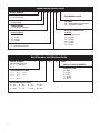
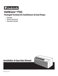
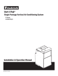
Model Identification Guide
MODEL NUMBER
V
E
A
24 K 50 RT A
SERIES
V=Vertical Series
ENGINEERING CODE
E=Cooling with or without electric heat
H=Heat Pump
OPTIONS
RT = Standard Remote Operation
SP = Seacoast Protected
DESIGN SERIES
A = 32" and 47" Cabinet
NOMINAL CAPACITY
A-Series (Btu/h)
09 = 9,000
12 = 12,000
18 = 18,000
24 = 24,000
ELECTRIC HEATER SIZE
A-Series
00 = No electric heat
25 = 2.5 KW
34 = 3.4 KW
50 = 5.0 KW
75 = 7.5 KW
10 = 10 KW
VOLTAGE
K = 208/230V-1Ph-60Hz
Serial Number Identification Guide
SERIAL NUMBER
Decade Manufactured
J=9
L=0
L
K
E=5
F=6
G=7
H=8
4
00001
PRODUCT LINE
R = RAC
P = PTAC
E = EAC
V = VPAK
H = SPLIT
J=9
K=0
MONTH MANUFACTURED
A = Jan
D = Apr
G = Jul
B = Feb
E = May
H = Aug
C = Mar
F = Jun
J = Sep
V
PRODUCTION RUN NUMBER
K = Not Used
YEAR MANUFACTURED
A=1
B=2
C=3
D=4
A
K = Oct
L = Nov
M = Dec
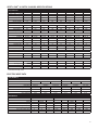
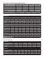
VERT-I-PAK® H SUFFIX CHASSIS SPECIFICATIONS
VEA/VHA9K-24K
VEA09K
C O O L I N G
H
E
A
P
VEA12K
VEA18K
VEA24K
VHA09K
VHA12K
VHA18K
VHA24K
11800/11500
1093
10.8
0.72
18000/17800
2070
8.7
0.70
24000
2526
9.5
0.70
9500/9300
905
10.5
0.74
11800/11500
1124
10.5
0.72
18000/17800
2070
8.7
0.70
23500
2474
9.5
0.70
N/A
N/A
N/A
N/A
N/A
N/A
N/A
N/A
N/A
N/A
N/A
N/A
8500/8300
3.0
830
4.4/4.9
10600/10400
3.2
971
5.5/6.1
15700/15500
3.0
1705
9.2/10.2
22500
3
2200
11.4
230/208
253-198
4.9/5.3
21
4.5
1/4
1.2
N/A
N/A
230/208
253-198
9.2/10.2
47
7.9
1/4
1.4
N/A
N/A
230/208
253-198
11.2/12.4
68
10.2
1/4
2
1/4
2
230/208
253-198
4.2/4.4
21
3.7
1/4
1.2
N/A
N/A
230/208
253-198
5.0/5.5
21
4.5
1/4
1.2
N/A
N/A
230/208
253-198
9.2/10.2
47
7.9
1/4
1.4
N/A
N/A
230/208
253-198
11.2/12.4
68
10.2
1/4
2
1/4
2
350
60
.3"
550
60
.3"
750
80
.3"
300
60
.3"
375
60
.3"
550
60
.3"
750
80
.3"
23 x 23 x 32
124
135
29
23 x 23 x 32
144
155
42
23 x 23 x 47
167
180
68.5
23 x 23 x 32
114
125
23.5
23 x 23 x 32
125
135
27
23 x 23 x 32
144
155
42
23 x 23 x 47
167
180
63.5
D A T A
Cooling Btu/h
9500/9300
Cooling Power (W)
880
EER
10.8
Sensible Heat Ratio
0.74
E A T P U M P D A T A
Heating Btu/h
N/A
COP @ 47°F
N/A
Heating Power (W)
N/A
Heating Current (A)
N/A
L E C T R I C A L D A T A
Voltage (1 Phase, 60 Hz)
230/208
Volt Range
253-198
Cooling Current (A)
4.1/4.3
Amps L.R.
21
Amps F.L.
3.7
Indoor Motor (HP)
1/4
Indoor Motor (A)
1.2
Outdoor Motor (HP)
N/A
Outdoor Motor (A)
N/A
I R F L O W D A T A
Indoor CFM*
300
Vent CFM
60
Max. ESP
.3"
H Y S I C A L D A T A
Dimensions (W x D x H)
23 x 23 x 32
Net Weight (Lbs)
114
Shipping Weight (Lbs)
125
R-22 Charge
25
* Normal Value Wet Coil @ .1" ESP.
ELECTRIC HEAT DATA
VEA / VHA09,12
Heater Watts
Voltage
Heating Btu/h
Heating Current (Amps)
Minimum Circuit Ampacity
Branch Circuit Fuse (Amps)
Basic Heater Size
2500/2050
8500/7000
10.6/9.3
15
15
2.5 Kw
VE/VHA09
3400/2780
230/208
11600/9500
14.5/12.5
19.9
20
3.4 Kw
5000/4090
2500/2050
17000/13900
20.9/18.2
27.9
30
5.0 Kw
8500/7000
10.6/9.3
15
15
2.5 Kw
VE/VHA12
3400/2780
230/208
11600/9500
14.5/12.5
19.9
20
3.4 Kw
5000/4090
17000/13900
20.9/18.2
27.9
30
5.0 Kw
VEA/VHA18,24
Heater Watts
Voltage
Heating Btu/h
Heating Current (Amps)
Minimum Circuit Ampacity
Branch Circuit Fuse (Amps)
Basic Heater Size
2500/2050
8500/7000
10.6/9.3
15
15
2.5 Kw
VE/VHA18
3400/2780
230/208
11600/9500
14.5/12.5
19.9
20
3.4 Kw
5000/4090
2500/2050
3400/2780
17000/13900
20.9/18.2
27.9
30
5.0 Kw
8500/7000
10.9/9.9
17.2/15.9
25/25
2.5 Kw
11600/9500
14.8/13.4
22.1/20.3
25/25
3.4 Kw
VE/VHA24
5000/4090
230/208
17000/13900
21.7/19.7
30.7/28.1
35/30
5.0 Kw
7500/6135
10000/8180
25598/20939
32.6/29.5
44.3/40.4
45/45
7.5 Kw
34130/27918
43.5/39.3
57.9/52.7
60/60
10.0 Kw
5
VERT-I-PAK® E & G SUFFIX CHASSIS SPECIFICATIONS
Model
Voltage (V)
Refrigerant
Chassis Width
Chassis Depth
Chassis Height **
Shipping W x D x H
Supply Duct Collar ***
Drain Connection
Min. Circuit Amps
CFM Indoor
Max. Duct ESP
V(E,H)A09
230 / 208
R-22
23.125"
23.125"
32.25"
26" x 28.5" x 35.0"
10"
3/4" FPT
V(E,H)A12
V(E,H)A18
230 / 208
230 / 208
R-22
R-22
23.125"
23.125"
23.125"
23.125"
32.25"
32.25"
26." x 28.5" x 35"
26" x 28.5" x 35"
10"
10"
3/4" FPT
3/4" FPT
See Chassis Nameplate
Page 11
.3 in. water
.3 in. water
.3 in. water
V(E,H)A24
230 / 208
R-22
23.125"
23.125"
47.25"
26" x 28.5" x 50"
10"
3/4" FPT
.3 in. water
** Height includes 2" duct collar & isolators under unit. *** Factory collar accepts 10" flex duct.
VEA / VHA9K-24K
VEA09K
C O O L I N G D A T A
Cooling Btu/h
9500/9300
Cooling Power (W)
880
EER
10.8
Sensible Heat Ratio
0.74
H E A T P U M P D A T A
Heating Btu/h
N/A
COP @ 47°F
N/A
Heating Power (W)
N/A
Heating Current (A)
N/A
E L E C T R I C A L D A T A
Voltage (1 Phase, 60 Hz)
230/208
Volt Range
253-198
Cooling Current (A)
4.1/4.3
Amps L.R.
21
Amps F.L.
3.7
Indoor Motor (HP)
1/4
Indoor Motor (A)
1.2
Outdoor Motor (HP)
N/A
Outdoor Motor (A)
N/A
A I R F L O W D A T A
Indoor CFM*
300
Vent CFM
60
Max. ESP
.3"
P H Y S I C A L D A T A
Dimensions (W x D x H)
23x23x32
Net Weight (Lbs)
114
Shipping Weight (Lbs)
125
R-22 Charge
25
VEA12K
VEA18K
VEA24K
VHA09K
VHA12K
VHA18K
VHA24K
11800/11500
1093
10.8
0.72
18000/17800
2070
8.7
0.70
24000
2526
9.5
0.70
9500/9300
905
10.5
0.74
11800/11500
1124
10.5
0.72
18000/17800
2070
8.7
0.70
23500
2474
9.5
0.70
N/A
N/A
N/A
N/A
N/A
N/A
N/A
N/A
N/A
N/A
N/A
N/A
8500/8300
3.0
830
4.4/4.9
10600/10400
3.2
971
5.5/6.1
15700/15500
3.0
1705
9.2/10.2
22500
3
2200
11.4
230/208
253-198
4.9/5.3
21
4.5
1/4
1.2
N/A
N/A
230/208
253-198
9.2/10.2
47
7.9
1/4
1.4
N/A
N/A
230/208
253-198
11.2/12.4
68
10.2
1/4
2
1/4
2
230/208
253-198
4.2/4.4
21
3.7
1/4
1.2
N/A
N/A
230/208
253-198
5.0/5.5
21
4.5
1/4
1.2
N/A
N/A
230/208
253-198
9.2/10.2
47
7.9
1/4
1.4
N/A
N/A
230/208
253-198
11.2/12.4
68
10.2
1/4
2
1/4
2
350
60
.3"
550
60
.3"
750
80
.3"
300
60
.3"
375
60
.3"
550
60
.3"
750
80
.3"
23x23x32
124
135
29
23x23x32
144
155
42
23x23x47
167
180
68.5
23x23x32
114
125
23.5
23x23x32
125
135
27
23x23x32
144
155
42
23x23x47
167
180
63.5
* Normal Value Wet Coil @ .1" ESP.
ELECTRIC HEAT DATA
VEA / VHA09,12
Heater Watts
Voltage
Heating Btu/h
Heating Current (Amps)
Minimum Circuit Ampacity
Branch Circuit Fuse (Amps)
Basic Heater Size
2500/2050
8500/7000
10.6/9.3
15
15
2.5 Kw
VE/VHA09
3400/2780
230/208
11600/9500
14.5/12.5
19.9
20
3.4 Kw
5000/4090
2500/2050
17000/13900
20.9/18.2
27.9
30
5.0 Kw
8500/7000
10.6/9.3
15
15
2.5 Kw
VE/VHA12
3400/2780
230/208
11600/9500
14.5/12.5
19.9
20
3.4 Kw
5000/4090
17000/13900
20.9/18.2
27.9
30
5.0 Kw
VEA / VHA18,24
Heater Watts
Voltage
Heating Btu/h
Heating Current (Amps)
Minimum Circuit Ampacity
Branch Circuit Fuse (Amps)
Basic Heater Size
6
2500/2050
8500/7000
10.6/9.3
15
15
2.5 Kw
VE/VHA18
3400/2780
230/208
11600/9500
14.5/12.5
19.9
20
3.4 Kw
5000/4090
2500/2050
3400/2780
17000/13900
20.9/18.2
27.9
30
5.0 Kw
8500/7000
10.9/9.9
17.2/15.9
25/25
2.5 Kw
11600/9500
14.8/13.4
22.1/20.3
25/25
3.4 Kw
VE/VHA24
5000/4090
230/208
17000/13900
21.7/19.7
30.7/28.1
35/30
5.0 Kw
7500/6135
10000/8180
25598/20939
32.6/29.5
44.3/40.4
45/45
7.5 Kw
34130/27918
43.5/39.3
57.9/52.7
60/60
10.0 Kw
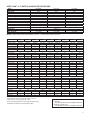
VERT-I-PAK® A - D SUFFIX CHASSIS SPECIFICATIONS
Model
Voltage (V)
Refrigerant
Chassis Width
Chassis Depth
Chassis Height **
Shipping W x D x H
Supply Duct Collar ***
Drain Connection
Drain Hose ****
Thermostat Harness
Power Cord
Min. Circuit Amps
CFM Indoor
Fan Speeds
Max. Duct ESP
V(E,H)A09
230 / 208
R-22
23.125"
23.125"
32.25"
26" x 28" x 35"
10"
1/2" MPT
12" long
36" long
60" long
2
.3 In. water
V(E,H)A12
230 / 208
R-22
23.125"
23.125"
32.25"
26" x 28" x 35"
10"
1/2" MPT
12" long
36" long
60" long
See Chassis Nameplate
Page 15
2
.3 In. water
V(E,H)A18
230 / 208
R-22
23.125"
23.125"
32.25"
26" x 28" x 35"
10"
1/2" MPT
12" long
36" long
60" long
2
.3 In. water
NOTES: ** Height includes 2" duct collar & isolators under unit. *** Factory collar accepts 10" flex duct.
MODELS
V(E,H)A09K25 V(E,H)A09K34 V(E,H)A09K50 V(E,H)A12K25 V(E,H)A12K34 V(E,H)A12K50 V(E,H)A18K25 V(E,H)A18K34 V(E,H)A18K50
Cooling Cap. (Btu/h)
9500/9300
9500/9300
9500/9300
11500/11300
11500/11300
11500/11300
17200/17000
17200/17000
17200/17000
Cooling Power (W)
950
950
950
1200
1200
1200
1911
1911
1911
SEER
10.0
10.0
10.0
10.0
10.0
10.0
10.0
10.0
10.0
Water Removal (Pts/h)
2.1
2.1
2.1
2.8
2.8
2.8
4.0
4.0
4.0
Cooling SHR
0.77
0.77
0.77
0.76
0.76
0.76
0.75
0.75
0.75
Heater Size (KW)
2.5
3.4
5.0
2.5
3.4
5.0
2.5
3.4
5.0
Heating Cap.(Btu/h)
8500/7000
11600/9500
17000/13900
8500/7000
11600/9500
17000/13900
8500/7000
11600/9500
17000/13900
Heating Power (W)
2500/2050
3500/2780
5000/4090
2500/2050
3500/2780
5000/4520
2500/2050
3500/2780
5000/4520
Heating Current (A)
11.9/11.2
15.9/14.6
22.6/20.6
11.9/11.2
15.9/14.6
22.6/20.6
11.9/11.2
15.9/14.6
22.6/20.6
Heating Cap.(Btu/h)
8000/7800
8000/7800
8000/7800
11200/11000
11200/11000
11200/11000
15700/15500
15700/15500
15700/15500
Heating Power (W)
950
950
950
1200
1200
1200
1830
1830
1830
Heating Current (A)
4.4/4.9
4.4/4.9
4.4/4.9
5.2/6.0
5.2/6.0
5.2/6.0
9.0/10.0
9.0/10.0
9.0/10.0
3.0
3.0
3.0
3.0
3.0
3.0
2.4
2.4
2.4
230/208
230/208
230/208
230/208
230/208
230/208
230/208
230/208
230/208
20
20
20
26.3
26.0
26.3
45
45
45
Cooling Current (A)
4.4/4.9
4.4/4.9
4.4/4.9
5.5/6.1
5.2/6.0
5.2/6.0
7.6
7.6
7.6
MIN. Ckt. Amps (A)
15
20
30
15
20
30
15
20
30
COP @ 470 F
Voltage (V)
LRA - Comp. (A)
Power Connection
Refrigerant
POWER CORD
POWER CORD
POWER CORD WITH OPTION TO HARD WIRE
R-22
R-22
R-22
R-22
R-22
R-22
R-22
R-22
R-22
Unit Width (in.)
23.125
23.125
23.125
23.125
23.125
23.125
23.125
23.125
23.125
Unit Depth (in.)
23.125
23.125
23.125
23.125
23.125
23.125
23.125
23.125
23.125
Unit Height* (in.)
32.25
32.25
32.25
32.25
32.25
32.25
32.25
32.25
32.25
Shipping Weight (lbs.)
125
125
125
135
135
135
155
155
155
Indoor CFM **
300
300
300
375
375
375
550
550
550
Fresh Air CFM**
60
60
60
60
60
60
60
60
60
230V, 1/4 HP
230V, 1/4 HP
230V, 1/4 HP
230V, 1/4 HP
230V, 1/4 HP
230V, 1/4 HP
230V, 1/4 HP
230V, 1/4 HP
230V, 1/4 HP
1.4
1.4
1.4
1.4
1.4
1.4
1.4
1.4
1.4
Motor
Motor Amps**
*Height includes 2" high duct collar and 5/8" isolators under unit.
**Normal Value Dry Coil on High Speed @ .3" ESP.
Due to continuing research in new energy-saving technology,
specifications are subject to change without notice.
Capacity rated at standard conditions:
COOLING–
950F DB/750F WB outdoor, 800F DB/670F WB indoor
HEATING– (reverse cycle)
470F DB/430F WB outdoor, 700F DB/600F WB indoor
7
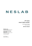
Sequence of Operation
A good understanding of the basic operation of the refrigeration
system is essential for the service technician. Without this
understanding, accurate troubleshooting of refrigeration
system problems will be more difficult and time consuming,
if not (in some cases) entirely impossible. The refrigeration
system uses four basic principles (laws) in its operation they
are as follows:
1. "Heat always flows from a warmer body to a cooler
body."
2. "Heat must be added to or removed from a substance
before a change in state can occur"
3. "Flow is always from a higher pressure area to a lower
pressure area."
4. "The temperature at which a liquid or gas changes state
is dependent upon the pressure."
The refrigeration cycle begins at the compressor. Starting
the compressor creates a low pressure in the suction line
which draws refrigerant gas (vapor) into the compressor.
The compressor then "compresses" this refrigerant, raising
its pressure and its (heat intensity) temperature.
The refrigerant leaves the compressor through the discharge
line as a HOT high pressure gas (vapor). The refrigerant
enters the condenser coil where it gives up some of its
heat. The condenser fan moving air across the coil's finned
surface facilitates the transfer of heat from the refrigerant to
the relatively cooler outdoor air.
When a sufficient quantity of heat has been removed from the
refrigerant gas (vapor), the refrigerant will "condense" (i.e.)
change to a liquid). Once the refrigerant has been condensed
(changed) to a liquid it is cooled even further by the air that
continues to flow across the condenser coil.
The Vert-I-Pak design determines at exactly what point
(in the condenser) the change of state (i.e. gas to a liquid)
takes place. In all cases, however, the refrigerant must be
totally condensed (changed) to a liquid before leaving the
condenser coil.
The refrigerant leaves the condenser coil through the liquid
line as a WARM high pressure liquid. It next will pass through
the refrigerant drier (if so equipped). It is the function of the
drier to trap any moisture present in the system, contaminants,
and LARGE particulate matter.
The liquid refrigerant next enters the metering device. The
metering device is a capillary tube. The purpose of the
metering device is to "meter" (i.e. control or measure) the
quantity of refrigerant entering the evaporator coil.
In the case of the capillary tube this is accomplished (by
design) through size (and length) of device, and the pressure
difference present across the device.
Since the evaporator coil is under a lower pressure (due to
the suction created by the compressor) than the liquid line,
the liquid refrigerant leaves the metering device entering the
evaporator coil. As it enters the evaporator coil, the larger
area and lower pressure allows the refrigerant to expand
and lower its temperature (heat intensity). This expansion is
often referred to as "boiling". Since the unit's blower is moving
Indoor air across the finned surface of the evaporator coil,
the expanding refrigerant absorbs some of that heat. This
results in a lowering of the indoor air temperature, hence the
"cooling" effect.
The expansion and absorbing of heat cause the liquid
refrigerant to evaporate (i.e. change to a gas). Once the
refrigerant has been evaporated (changed to a gas), it is
heated even further by the air that continues to flow across
the evaporator coil.
The particular system design determines at exactly what
point (in the evaporator) the change of state (i.e. liquid to a
gas) takes place. In all cases, however, the refrigerant must
be totally evaporated (changed) to a gas before leaving the
evaporator coil.
The low pressure (suction) created by the compressor causes
the the refrigerant to leave the evaporator through the suction
line as a COOL low pressure vapor. The refrigerant then
returns to the compressor, where the cycle is repeated.
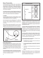
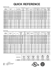
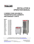
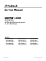
Refrigeration Assembly
1.
2.
3.
4.
5.
8
Compressor
Evaporator Coil Assembly
Condenser Coil Assembly
Capillary Tube
Compressor Overload
Electrical Supply
Supply Voltage
WARNING: Electrical shock hazard.
To insure proper operation, supply voltage to the system
should be within five (5) percent (plus or minus) of listed
rating plate voltage.
Turn OFF electric power at fuse box or service panel
before making any electrical connections and ensure a
proper ground connection is made before connecting line
voltage.
All electrical connections and wiring MUST be installed by
a qualified electrician and conform to the National Electrical
Code and all local codes which have jurisdiction.
Failure to do so can result in property damage, personal
injury and/or death.
Supply Circuit
The system cannot be expected to operate correctly unless
the system is properly connected (wired) to an adequately
sized single branch circuit. Check the installation manual
and/or technical data for your particular unit and/or strip
heaters to determine if the circuit is adequately sized.
Electrical Rating Tables
A through D Suffix
250 V Receptacles and Fuse Types
Units Only
15
To insure proper system operation, the transformer
secondary output must be maintained at a nominal 24 volts.
The control (low) voltage transformer is equipped with
multiple primary voltage taps. Connecting the primary,
(supply) wire to the tap (i.e., 208 and 240 volts) that most
closely matches the MEASURED supply voltage will insure
proper transformer secondary output is maintained.
Supply Voltage
Supply voltage to the unit should be a nominal 208/230 volts.
It must be between 197 volts and 253 volts. Supply voltage
to the unit should be checked WITH THE UNIT IN
OPERATION. Voltage readings outside the specified range
can be expected to cause operating problems. Their cause
MUST be investigated and corrected.
Electrical Ground
NOTE: Use copper conductors ONLY
Wire sizes are per NEC. Check local codes for
overseas applications
AMPS
Control (Low) Voltage
20 *
30
GROUNDING OF THE ELECTRICAL SUPPLY TO ALL
UNITS IS REQUIRED for safety reasons.
Electrical Requirements
NOTE:
All field wiring must comply with
NEC and local codes. It is the
responsibility of the installer to
insure that the electrical codes are
met.
Wire Size
Use ONLY wiring size recommended
for single outlet branch circuit.
RECEPTACLE
MANUFACTURER
Hubbell
P&S
GE
Arrow-Hart
PART NUMBERS
5661
5661
GE4069-1
5661
TIME-DELAY TYPE
FUSE
5461
9330
5871
5930
GE4182-1 GE4139-3
5861
5700
15
20
Fuse/Circuit Use ONLY type and size fuse or
HACR circuit breaker
Breaker
Indicated on unit's rating plate (See
sample on page 6).
Proper current protection to the unit
is the responsibility of the owner.
Grounding
Unit MUST be grounded from branch
circuit to unit, or through separate
ground wire provided on permanently
connected units. Be sure that branch
circuit or general purpose outlet is
grounded.
Wire Sizing
Use recommended wire size given in
the tables below and install a single
branch circuit. All wiring must comply
with local and national codes. NOTE:
Use copper conductors only.
30
(or HACR circuit breaker)
HACR — Heating, Air Conditioning, Refrigeration
* May be used for 15 Amp applications if fused for 15 Amp
Recommended branch circuit wire sizes*
Nameplate maximum circuit
breaker size
15A
20A
30A
AWG Wire size**
14
12
10
AWG — American Wire Gauge
* Single circuit from main box
** Based on copper wire, single insulated conductor at 60°C
9
Room Thermostats
Thermostat Location
Room thermostats are available from several different
manufacturers in a wide variety of styles. They range from
the very simple Bimetallic type to the complex electronic
set-back type. In all cases, no matter how simple or
complex, they are simply a switch (or series of switches)
designed to turn equipment (or components) "ON" or "OFF"
at the desired conditions.
An improperly operating, or poorly located room thermostat
can be the source of perceived equipment problems. A
careful check of the thermostat and wiring must be made
then to insure that it is not the source of problems.
Location
The thermostat should not be mounted where it may be
affected by drafts, discharge air from registers (hot or cold),
or heat radiated from the sun or appliances.
The thermostat should be located about 5 Ft. above the
floor in an area of average temperature, with good air
circulation. Close proximity to the return air grille is the
best choice.
Mercury bulb type thermostats MUST be level to control
temperature accurately to the desired set-point. Electronic
digital type thermostats SHOULD be level for aesthetics.
Measuring Current Draw
In order to accomplish this, the heat output from the
anticipator must be the same regardless of the current
flowing through it. Consequently, some thermostats have
an adjustment to compensate for varying current draw in
the thermostat circuits.
The proper setting of heat anticipators then is important
to insure proper temperature control and customer
satisfaction. A Heat anticipator that is set too low will
cause the heat source to cycle prematurely possibly never
reaching set point. A heat anticipator that is set too high
will cause the heat source to cycle too late over shooting
the set point.
The best method to obtain the required setting for the
heat anticipator, is to measure the actual current draw in
the control circuit ("W") using a low range (0-2.0 Amps)
Ammeter. After measuring the current draw, simply set
the heat anticipator to match that value.
If a low range ammeter is not available, a "Clamp-on" type
ammeter may be used as follows:
Heat Anticipators
Heat anticipators are small resistance heaters (wired
in series with the "W" circuit) and built into most
electromechanical thermostats. Their purpose is to prevent
wide swings in room temperature during system operation
in the HEATING mode. Since they are wired in series,
the "W" circuit will open if one burns out preventing heat
operation.
The heat anticipator provides a small amount of heat to
the thermostat causing it to cycle (turn off) the heat source
just prior to reaching the set point of the thermostat. This
prevents exceeding the set point.
10
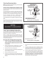
1.
Wrap EXACTLY ten (10) turns of wire around the jaws
of a clamp-on type ammeter.
2.
Connect one end of the wire to the "W" terminal of
the thermostat sub-base, and the other to the "R"
terminal.
3.
Turn power on, and wait approximately 1 minute, then
read meter.
4.
Divide meter reading by 10 to obtain correct anticipator
setting.
Electronic thermostats do not use a resistance type
anticipator. These thermostats use a microprocessor
(computer) that determines a cycle rate based on a
program loaded into it at the factory.
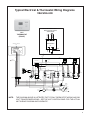
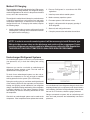
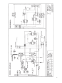
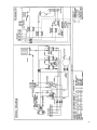
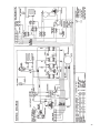
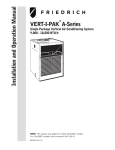
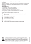
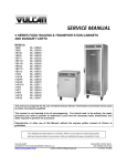
Typical Electrical & Thermostat Wiring Diagrams
VEA/VHA 24K
FOR 208 VOLT MODELS ONLY
MOVE THE WHITE WIRE AS
SHOWN BELOW
WHITE
BLACK
RT2
THERMOSTAT
(FRONT)
COM. 208V
240V
TRANSFORMER
THERMOSTAT CONNECTIONS
(EAR)
24V
UP
G
R
R
W
B
Y
C
RED
BLACK
WHITE
RED
YELLOW
HEATER
2.5 KW & 3.4 KW
5 KW
BROWN
HEATER
7.5 KW & 10 KW
COIL, SOLENOID
RED
QUICK DISCONNECT
RED
L1
L2
RED
BLACK
BLACK
RED
W Y
R
G
B
M
WHITE
24V
2
4
1
3
BLACK
C
LOW AMBIENT
CONTROL
RED
CAPACITOR
RED
RED
RED
WHITE
PRESSURE
SWITCH
COM. 208V 240V
TRANSFORMER
HER
FAN
TERM BOARD
WHITE
2
4
1
3
HEAT
RELAY
HEAT
RELAY
REV VALVE
RELAY
FAN
RELAY
COMPR RELAY
YELLOW
c
BLACK
BLUE
RED
"F"
"F"C"F"
R
S
COMPRESSOR
RED
BLACK
BLACK
BLUE
RED
COMP WIRE HARNESS
YELLOW
WHITE
WHITE
2
4
2
4
1
3
1
3
(2.5KW/3.4KW
5 KW)
2
4
1
3
BLACK
BLACK
RED
BLACK
(2.5KW/3.4KW
5 KW)
BLACK
BLACK
HEAT
RELAY
(7.5KW/10KW)
2
4
1
3
HEAT
RELAY
(7.5KW/10KW)
2
4
1
3
BLACK
BLACK
WIRE NUT (RED)
GREEN
BLACK
SEE NOTE #6
BLACK
RED
BLUE
GREEN
BROWN
RED
C
YELLOW
T-STAT
DEFROST
H
BLACK
INSULATOR
L
WHITE
2-REQ'D
GREEN
WHITE
CAPACITOR
c
NOTE:
CONDENSER
MOTOR
BROWN
FAN
GREEN
TO MOTOR
MOUNT
BLUE
WHITE
WHITE
HE
RM
BROWN
TO MOTOR
MOUNT
WIRE NUT (RED)
BLOWER
MOTOR
SEE NOTE #4
BLACK
THE DIAGRAM ABOVE ILLUSTRATES THE TYPICAL THERMOSTAT WIRING AND 208
VOLT TRANSFORMER WIRING. SEE THE UNIT CONTROL PANEL FOR THE ACTUAL
UNIT WIRING DIAGRAM AND SCHEMATIC.
11
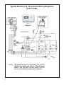
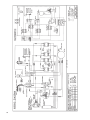
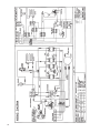
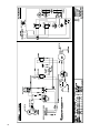
Typical Electrical & Thermostat Wiring Diagrams
G & H Suffix
COM. 208V 240V
RT1
THERMOSTAT
(FRONT)
NOTE:
12
THE DIAGRAM ABOVE ILLUSTRATES THE TYPICAL
THERMOSTAT WIRING AND 208 VOLT TRANSFORMER
WIRING. SEE THE UNIT CONTROL PANEL FOR THE
ACTUAL UNIT WIRING DIAGRAM AND SCHEMATIC.
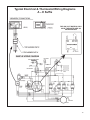
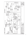
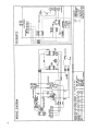
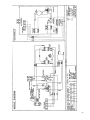
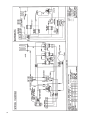
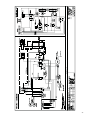
Typical Electrical & Thermostat Wiring Diagrams
A – E Suffix
FOR 208 VOLT MODELS ONLY:
MOVE THE WHITE WIRE AS
SHOWN BELOW.
13
Indoor Blower - Airflow
Heating (Electric)
The current Vert-I-Pak 9, 12, & 18 use a dual shaft, permanent
split capacitor, single speed motor to drive indoor blower and
outdoor fan. Earlier model VERT-I-Pak units used 2-speed
motors. The Vert-I-Pak 24 uses an individual, single shaft,
permanent split capacitor, single speed motor for the indoor
blower, and a separate motor drives the outdoor fan.
When using electric heaters, select the blower speed that
provides adequate airflow across the elements to prevent
overheating and cycling on limit and/or premature failure.
CHECK THE EXTERNAL STATIC PRESSURE, and then
consult the AIR FLOW DATA to determine the ACTUAL air
flow delivered for the factory selected fan speed. This will
be especially important on change-outs using an existing
duct system that may not have been properly sized to
begin with.
Different size (HP) motors and/or different diameter blower
wheels are used in different models to obtain the required
airflow.
Indoor Blower - Airflow
The current Vert-I-Pak 9, 12, & 18 use a dual shaft, permanent
split capacitor, single speed motor to drive indoor blower and
outdoor fan. Earlier model VERT-I-Pak units used 2-speed
motors. The Vert-I-Pak 24 uses an individual, single shaft,
permanent split capacitor, single speed motor for the indoor
blower, and a separate motor drives the outdoor fan.
Different size (HP) motors and/or different diameter blower
wheels are used in different models to obtain the required
airflow.
Condenser Fan Motors
The current Vert-I-Pak 9, 12, & 18 units use a dual shaft,
permanent split capacitor, single speed motor to drive indoor
and outdoor fan. Earlier models used a 2-speed motor. The
Vert-I-Pak 24 uses and individual, single shaft, permanent
split capacitor, single speed motor for the outdoor fan, with a
separate motor driving the indoor blower.
Blower Wheel Inspection
Visually inspect the blower wheel for the accumulations
of dirt or lint since they can cause reduced airflow. Clean
the blower wheel of these accumulations. If accumulation
cannot be removed, it will be necessary to remove the
blower assembly from the unit for proper wheel cleaning.
Cooling
A nominal 400 (350-450 allowable) CFM per ton of airflow
is required to insure proper system operation, capacity,
and efficiency. Factory-set blower speeds should provide
the proper airflow for the size (Cooling capacity) of the unit
when connected to a properly sized duct system.
Cooling (VEA/VHA 24)
When the thermostat is set for cooling mode (SYSTEM
switch set to COOL and FAN switch to AUTO) a rise in room
temperature will make It also causes a 24-volt signal on the
“Y” thermostat conductor through the high pressure and low
ambient switches energizing the compressor relay, turning
on the compressor and outdoor fan motor. A 24-volt signal
on the “G” thermostat terminal to the Fan Relay, turning on
the indoor blower motor.
14
Heating (VEA/VHA 24)
When the thermostat is set for heating mode (System switch
set to HEAT and FAN switch to AUTO) it will make a 24volt signal on the “B” thermostat terminal to energize the
Reversing Valve Relay. A drop in room temperature, will
make a 24-volt signal on the “W” thermostat terminal to the
Defrost Thermostat, and “G” thermostat terminal to the Fan
Relay. The Defrost Thermostat will determine whether the
unit should run in Heat Pump, or Electric Heat, based on the
outdoor temperature. (See Defrost Thermostat page 24)
External Static Pressure
External Static Pressure can best be defined as the pressure
difference (drop) between the Positive Pressure (discharge)
and the Negative Pressure (intake) sides of the blower.
External Static Pressure is developed by the blower as a
result of resistance to airflow (Friction) in the air distribution
system EXTERNAL to the VERT-I-PAK cabinet.
Resistance applied externally to the VERT-I-PAK (i.e. duct
work, coils, filters, etc.) on either the supply or return side
of the system causes an INCREASE in External Static
Pressure accompanied by a REDUCTION in airflow.
External Static Pressure is affected by two (2) factors.
1.
Resistance to Airflow as already explained.
2. Blower Speed. Changing to a higher or lower blower
speed will raise or lower the External Static Pressure
accordingly.
These affects must be understood and taken into consideration
when checking External Static Pressure/Airflow to insure that
the system is operating within design conditions.
Operating a system with insufficient or excessive airflow
can cause a variety of different operating problems.
Among these are reduced capacity, freezing evaporator
coils, premature compressor and/or heating component
failures. etc.
System airflow should always be verified upon completion
of a new installation, or before a change-out, compressor
replacement, or in the case of heat strip failure to insure
that the failure was not caused by improper airflow.
Checking External Static Pressure
The airflow through the unit can be determined by
measuring the external static pressure of the system, and
consulting the blower performance data for the specific
VERT-I-PAK.
1. Set up to measure external static pressure at the
supply and return air.
2. Drill holes in the supply duct for pressure taps, pilot
tubes or other accurate pressure sensing devices.
3. Connect these taps to a level inclined manometer
or Magnehelic gauges.
4. Ensure the coil and filter are clean, and that all the
registers are open.
5. Determine the external static pressure with the
blower operating.
the case of the VERT-I-PAK, the condensate will cause
a reduction in measured External Static Pressure for the
given airflow.
It is also important to remember that when dealing with
VERT-l-PAK units that the measured External Static
Pressure increases as the resistance is added externally
to the cabinet. Example: duct work, filters, grilles.
Checking Approximate Airflow
If an inclined manometer or Magnehelic gauge is not
available to check the External Static Pressure, or the
blower performance data is unavailable for your unit,
approximate air flow call be calculated by measuring the
temperature rise, then using tile following criteria.
KILOWATTS x 3413
Temp Rise x 1.08
= CFM
6. Refer to the Air Flow Data for your VERT-I-PAK
system to find the actual airflow for factory-selected
fan speeds.
Electric Heat Strips
7. If the actual airflow is either too high or too low, the
blower speed will need to be changed.
DO NOT simply use the Kilowatt Rating of the heater (i.e.
2.5, 3.4, 5.0) as this will result in a less-than-correct airflow
calculation. Kilowatts may be calculated by multiplying
the measured voltage to the unit (heater) times the
measured
current draw of all heaters (ONLY) in operation to obtain
watts. Kilowatts are than obtained by dividing by 1000.
8. Select a speed, which most closely provides the
required airflow for the system.
9. Recheck the external static pressure with the
new speed. External static pressure (and actual
airflow) will have changed to a higher or lower value
depending upon speed selected. Recheck the actual
airflow (at this "new" static pressure) to confirm
speed selection.
10.
Repeat steps 8 and 9 (if necessary) until proper
airflow has been obtained.
EXAMPLE: Airflow requirements are calculated as follows:
(Having a wet coil creates additional resistance to airflow.
This addit ional resistance must be taken into consideration
to obtain accurate airflow information.
1 ½ TON SYSTEM ( 18,000 Btu)
Operating on high speed @ 230 volts with dry coil
measured external static pressure .20
The approximate CFM actually being delivered can be
calculated by using the following formula:
EXAMPLE: Measured voltage to unit (heaters) is 230 volts.
Measured Current Draw of strip heaters is 11.0 amps.
230 x 11.0 = 2530
2530/1000 = 2.53 Kilowatts
2.53 x 3413 = 8635
Supply Air
Return Air
Temperature Rise
95°F
75°F
20 °
20 x 1.08 = 21.6
8635
21.6
= 400 CFM
Air Flow = 500 CFM
In the same SYSTEM used in the previous example but
having a WET coil you must use a correction factor of
.94 (i.e. 500 x .94=470 CFM) to allow for the resistance
(internal) of the condensate on the coil.
It is important to use the proper procedure to check external
Static Pressure and determine actual airflow. Since in
IMPORTANT: FLEX DUCT CAN COLLAPSE AND
CAUSE AIRFLOW RESTRICTIONS. DO NOT
USE FLEX DUCT FOR: 90 DEGREE BENDS, OR
UNSUPPORTED RUNS OF 5 FT. OR MORE.
15
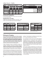
Airflow Charts A – D Suffix
Chart A
CFM @ 230 Volts - DRY COIL
Model —> V(E,H)A09/A12
V(E,H)A18
Chart B
Fan Speed —>
ESP (in water)
High
CFM
Low
CFM
High
CFM
Low
CFM
To Correct for:
0.00
N/A
427
N/A
0.10
411
387
0.20
373
0.30
327
Correction Factors
Correction
Factor
230 Volts
1.00
517
208 Volts
0.97
510
480
Dry Coil
1.00
347
500
470
Wet Coil
0.94
310
490
460
Ductwork Preparation
Pull the flex duct tight. Extra flex duct slack can greatly
increase static pressure
Explanation of charts
Chart A is the nominal dry coil VERT-I-PAK CFMs. Chart
B is the correction factors beyond nominal conditions.
Chart A – CFM
Chart B – Correction Multipliers
Model
18000
12000 / 9000
.00
520
420
230V
.10
510
410
208V
0.97
.20
500
370
Heating
1.00
.30
490
330
Cooling
0.95
Chart C – VE/VHA CFM
VEA/VHA24K
Correction Multipliers for:
1.00
.1" ESP
.2" ESP
.3" ESP
.4" ESP
Low
750
725
700
675
High
815
780
745
700
All values listed are inches W.C. with a wet
indoor coil with filter installed.
Refrigerant Charging
Note: Because the earlier model Vert-I- Paks are sealed
systems, service process tubes will have to be installed.
First install a line tap and remove refrigerant from system.
The H suffix model Vert-I-Paks have factory installed service values. Make necessary sealed system repairs and
vacuum system. Weigh in charge according to the unit data
plate. Crimp process tube line and solder end shut. Do
not leave a service valve in the sealed system.
Proper refrigerant charge is essential to proper unit
operation. Operating a unit with an improper refrigerant
charge will result in reduced performance (capacity) and/or
efficiency. Accordingly, the use of proper charging methods
during servicing will insure that the unit is functioning as
designed and that its compressor will not be damaged.
Too much refrigerant (overcharge) in the system is just as
bad (if not worse) than not enough refrigerant (undercharge).
They both can be the source of certain compressor
failures if they remain uncorrected for any period of time.
Quite often, other problems (such as low air flow across
evaporator, etc.) are misdiagnosed as refrigerant charge
16
problems. The refrigerant circuit diagnosis chart will assist
you in properly diagnosing these systems.
An overcharged unit will at times return liquid refrigerant
(slugging) back to the suction side of the compressor
eventually causing a mechanical failure within the
compressor. This mechanical failure can manifest itself
as valve failure, bearing failure, and/or other mechanical
failure. The specific type of failure will be influenced by the
amount of liquid being returned, and the length of time the
slugging continues.
Not enough refrigerant (Undercharge) on the other hand,
will cause the temperature of the suction gas to increase
to the point where it does not provide sufficient cooling for
the compressor motor. When this occurs, the motor winding
temperature will increase causing the motor to overheat
and possibly cycle open the compressor overload protector.
Continued overheating of the motor windings and/or cycling
of the overload will eventually lead to compressor motor
or overload failure.
Method Of Charging
The acceptable method for charging the Vert-I-Pak system
is the Weighed in Charge Method. The weighed in charge
method is applicable to all units. It is the preferred method
to use, as it is the most accurate.
The weighed in method should always be used whenever
a charge is removed from a unit such as for a leak repair,
compressor replacement, or when there is no refrigerant
charge left in the unit. To charge by this method, requires
the following steps:
1.
Install a piercing valve to remove refrigerant from the
sealed system. (Piercing valve must be removed from
the system before recharging.)
2. Recover Refrigerant in accordance with EPA
regulations.
3. Install a process tube to sealed system.
4. Make necessary repairs to system.
5. Evacuate system to 300 microns or less.
6. Weigh in refrigerant with the property quantity of
R-22 refrigerant.
7.
Start unit, and verify performance.
8. Crimp the process tube and solder the end shut.
NOTE: In order to access the sealed system it will be necessary to install Schrader type
fittings to the process tubes on the discharge and suction of the compressor. Proper
recovery refrigerant procedures need to be adhered to as outlined in EPA Regulations.
THIS SHOULD ONLY BE ATTEMPTED BY QUALIFIED SERVICE PERSONNEL.
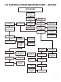
Undercharged Refrigerant Systems
An undercharged system will result in poor performance
(low pressures, etc.) in both the heating and cooling
cycle.
Whenever you service a unit with an undercharge of
refrigerant, always suspect a leak. The leak must be
repaired before charging the unit.
To check for an undercharged system, turn the unit on,
allow the compressor to run long enough to establish
working pressures in the system (15 to 20 minutes).
During the cooling cycle you can listen carefully at the exit
of the metering device into the evaporator; an intermittent
hissing and gurgling sound indicates a low refrigerant
charge. Intermittent frosting and thawing of the evaporator
is another indication of a low charge, however, frosting
and thawing can also be caused by insufficient air over
the evaporator.
Checks for an undercharged system can be made at the
compressor . If the compressor seems quieter than normal,
it is an indication of a low refrigerant charge. A check of the
amperage drawn by the compressor motor should show a
lower reading. (Check the Unit Specification.) After the unit
has run 10 to 15 minutes, check the gauge pressures.
Gauges connected to system with an undercharge will
have low head pressures and substantially low suction
pressures.
17
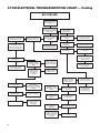
Overcharged Refrigerant Systems
Compressor amps will be near normal or higher.
Noncondensables can also cause these symptoms. To
confirm, remove some of the charge, if conditions improve,
system may be overcharged. If conditions don’t improve,
Noncondensables are indicated.
Whenever an overcharged system is indicated, always
make sure that the problem is not caused by air flow
problems. Improper air flow over the evaporator coil may
indicate some of the same symptoms as an overcharged
system.
An over charge can cause the compressor to fail, since it
would be "slugged" with liquid refrigerant.
The charge for any system is critical. When the compressor
is noisy, suspect an overcharge, when you are sure that
the air quantity over the evaporator coil is correct. Icing
of the evaporator will not be encountered because the
refrigerant will boil later if at all. Gauges connected to
system will usually have higher head pressure (depending
upon amount of overcharge). Suction pressure should be
slightly higher.
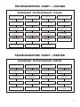
Restricted Refrigerant Systems
A quick check for either condition begins at the evaporator.
With a partial restriction, there may be gurgling sounds
at the metering device entrance to the evaporator. The
evaporator in a partial restriction could be partially frosted
or have an ice ball close to the entrance of the metering
device. Frost may continue on the suction line back to the
compressor.
Often a partial restriction of any type can be found by feel,
as there is a temperature difference from one side of the
restriction to the other.
With a complete restriction, there will be no sound at the
metering device entrance. An amperage check of the
compressor with a partial restriction may show normal
current when compared to the unit specification. With a
complete restriction the current drawn may be considerably
less than normal, as the compressor is running in a deep
vacuum (no load.) Much of the area of the condenser will
be relatively cool since most or all of the liquid refrigerant
will be stored there.
The following conditions are based primarily on a system
in the cooling mode.
Troubleshooting a restricted refrigerant system can
be difficult. The following procedures are the more
common problems and solutions to these problems.
There are two types of refrigerant restrictions: Partial
restrictions and complete restrictions.
A partial restriction allows some of the refrigerant to
circulate through the system.
With a complete restriction there is no circulation of
refrigerant in the system.
18
Restricted refrigerant systems display the same symptoms as
a "low-charge condition." When the unit is shut off, the gauges
may equalize very slowly. Gauges connected to a completely
restricted system will run in a deep vacuum. When the unit
is shut off, the gauges will not equalize at all.
Metering Device - Capillary Tube Systems
All units are equipped with capillary tube metering devices.
3.
Switch the unit to the heating mode and observe the
gauge readings after a few minutes running time. If
the system pressure is lower than normal, the heating
capillary is restricted.
4.
If the operating pressures are lower than normal
in both the heating and cooling mode, the cooling
capillary is restricted.
Checking for restricted capillary tubes.
1.
Connect pressure gauges to unit.
2.
Start the unit in the cooling mode. If after a few minutes
of operation the pressures are normal, the check valve
and the cooling capillary are not restricted.
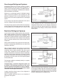
Reversing Valve Description/Operation
The Reversing Valve controls the direction of refrigerant
flow to the indoor and outdoor coils. It consists of a
pressure-operated, main valve and a pilot valve actuated
by a solenoid plunger. The solenoid is energized during
the heating cycle only. The reversing valves used in the
Vert-I-Pak system is a 2-position, 4-way valve
The single tube on one side of the main valve body is the
high-pressure inlet to the valve from the compressor. The
center tube on the opposite side is connected to the low
pressure (suction) side of the system. The other two are
connected to the indoor and outdoor coils. Small capillary
tubes connect each end of the main valve cylinder to the
"A" and "B" ports of the pilot valve. A third capillary is a
common return line from these ports to the suction tube
on the main valve body. Four-way reversing valves also
have a capillary tube from the compressor discharge tube
to the pilot valve.
The piston assembly in the main valve can only be shifted
by the pressure differential between the high and low sides
of the system. The pilot section of the valve opens and
closes ports for the small capillary tubes to the main valve
to cause it to shift.
NOTE: System operating pressures must be near
normal before valve can shift.
Electrical Circuit and Coil
(Reversing valve coil is energized in the heating cycle only).
1. Set controls for heating; valve should shift.
2. Check for line voltage at the heat relay, terminal #2
and L2 at the quick disconnect. If line voltage is not
present check the power supply.
Testing Coil
WARNING
1. Turn off high voltage electrical power to unit.
2. Unplug line voltage lead from reversing valve coil.
DANGER OF BODILY INJURY OR DEATH
FROM ELECTRICAL SHOCK
3. Check for electrical continuity through the coil. If you
do not have continuity replace the coil.
The reversing valve solenoid is connected to
high voltage. Turn off electrical power before
disconnecting or connecting high voltage wiring
or servicing valve.
4. Check from each lead of coil to the copper liquid line as
it leaves the unit or the ground lug. There should be no
continuity between either of the coil leads and ground;
if there is, coil is grounded and must be replaced.
5. If coil tests okay, reconnect the electrical leads .
6. Make sure coil has been assembled correctly.
19
Checking Reversing Valve
NOTE: You must have normal operating pressures before
the reversing valve can shift.
Check for proper refrigerant charge. Sluggish or sticky
reversing valves can sometimes be remedied by reversing
the valve several time with the airflow restricted to increase
system pressure.
To raise head pressure during the cooling season the airflow
through the outdoor coil can be restricted . During heating
the indoor air can be restricted by blocking the return air.
Dented or damaged valve body or capillary tubes can
prevent the main slide in the valve body from shifting.
If you determine this is the problem, replace the reversing
valve.
Reversing Valve in Heating Mode
After all of the previous inspections and checks have been
made and determined correct, then perform the “Touch
Test” on the reversing valve.
CAUTION
Never energize the coil when it is removed
from the valve, as a coil burnout will result.
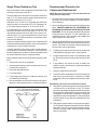
Touch Test in Heating/Cooling Cycle
The only definite indications that the slide is in the mid-position is if all three tubes on the suction side of the valve are
hot after a few minutes of running time.
NOTE: A condition other than those illustrated above, and
on page 19, indicate that the reversing valve is not shifting
properly. Both tubes shown as hot or cool must be the same
corresponding temperature.
Procedure For Changing Reversing Valve
1.
Install Process Tubes. Recover refrigerant from sealed
system. PROPER HANDLING OF RECOVERED
REFRIGERANT ACCORDING TO EPA REGULATIONS
IS REQUIRED.
2.
Remove solenoid coil from reversing valve. If coil is to
be reused, protect from heat while changing valve.
3.
Unbraze all lines from reversing valve.
4.
Clean all excess braze from all tubing so that they will
slip into fittings on new valve.
5.
Remove solenoid coil from new valve.
6.
Protect new valve body from heat while brazing with
plastic heat sink (ThermoTrap) or wrap valve body with
wet rag.
20
Reversing Valve in Cooling Mode
7.
Fit all lines into new valve and braze lines into new
valve.
8.
Pressurize sealed system with a combination of R-22
and nitrogen and check for leaks, using a suitable leak
detector. Recover refrigerant per EPA guidelines.
9.
Once the sealed system is leak free, install solenoid
coil on new valve and charge the sealed system by
weighing in the proper amount and type of refrigerant
as shown on rating plate. Crimp the process tubes
and solder the ends shut. Do not leave schrader or
piercing valves in the sealed system.
WARNING
DANGER OF BODILY INJURY OR DEATH
FROM ELECTRICAL SHOCK
Select the proper amperage scale and clamp the
meter probe around the wire to the "C" terminal of the
compressor.
When working on high voltage equipment - turn the
electrical power off before attaching test leads.
Turn on the unit and read the running amperage on the
meter. If the compressor does not start, the reading will
indicate the locked rotor amperage (L.R.A.).
Use test leads with alligator type clips - clip to terminals,
turn power on, take reading - turn power off before
removing leads.
External Overload
Compressor Checks
Locked Rotor Voltage (L.R.V.) Test
Locked rotor voltage (L.R.V.) is the actual voltage available
at the compressor under a stalled condition.
Single Phase Connections
Disconnect power from unit. Using a voltmeter, attach one
lead of the meter to the run "R" terminal on the compressor
and the other lead to the common "C" terminal of the compressor. Restore power to unit.
CAUTION
Make sure that the ends of the lead do not touch the
compressor shell since this will cause a short circuit.
Determine L.R.V.
Start the compressor with the voltmeter attached; then
stop the unit. Attempt to restart the compressor within a
couple of seconds and immediately read the voltage on the
meter. The compressor under these conditions will not start
and will usually kick out on overload within a few seconds
since the pressures in the system will not have had time to
equalize. Voltage should be at or above minimum voltage
of 197 VAC, as specified on the rating plate. If less than
minimum, check for cause of inadequate power supply; i.e.,
incorrect wire size, loose electrical connections, etc.
Amperage (L.R.A.) Test
The running amperage of the compressor is the most
important of these readings. A running amperage higher
than that indicated in the performance data indicates that
a problem exists mechanically or electrically.
Single Phase Running and L.R.A. Test
NOTE: Consult the specification and performance section
for running amperage. The L.R.A. can also be found on
the rating plate.
Some compressors are equipped with an external overload
which senses both motor amperage and winding temperature.
High motor temperature or amperage heats the overload
causing it to open, breaking the common circuit within the
compressor.
Heat generated within the compressor shell, usually due
to recycling of the motor, is slow to dissipate. It may take
anywhere from a few minutes to several hours for the
overload to reset.
Checking the External Overload
With power off, remove the leads from com pressor
terminals. If the compressor is hot, allow the overload
to cool before starting check. Using an ohmmeter, test
continuity across the terminals of the external overload. If
you do not have continuity; this indicates that the overload
is open and must be replaced.
Internal Overload
Some compressors are equipped with an internal overload
which senses both motor amperage and winding temperature.
High motor temperature or amperage heats the overload
causing it to open, breaking the common circuit within the
compressor. Heat generated within the compressor shell,
usually due to recycling of the motor, is slow to dissipate. It
may take anywhere from a few minutes to several hours for
the overload to reset.
Checking the Internal Overload
A reading of infinity (∞) between any two terminals MAY
indicate an open winding. If, however, a reading of infinity
(∞) is obtained between C & R and C & S, accompanied
by a resistance reading between S & R, an open internal
overload is indicated. Should you obtain this indication,
allow the compressor to cool (May take up to 24 hours) then
recheck before condemning the compressor. If an open
internal overload is indicated, the source of its opening must
be determined and corrected. Failure to do so will cause
repeat problems with an open overload and/or premature
compressor failure. Some possible causes of an open internal
overload include insufficient refrigerant charge, restriction in
the refrigerant circuit, and excessive current draw.
21
Single Phase Resistance Test
Remove the leads from the compressor terminals and set the
ohmmeter on the lowest scale (R x 1).
Touch the leads of the ohmmeter from terminals common to
start ("C" to "S"). Next, touch the leads of the ohmmeter from
terminals common to run ("C" to "R").
Add values "C" to "S" and "C" to "R" together and check resistance from start to run terminals ("S" to "R"). Resistance "S"
to "R" should equal the total of "C" to "S" and "C" to "R."
In a single phase PSC compressor motor, the highest value
will be from the start to the run connections (“S” to "R"). The
next highest resistance is from the start to the common connections ("S" to "C"). The lowest resistance is from the run to
common. ("C" to "R") Before replacing a compressor, check
to be sure it is defective.
Check the complete electrical system to the compressor and
compressor internal electrical system, check to be certain that
compressor is not out on internal overload.
Complete evaluation of the system must be made whenever
you suspect the compressor is defective. If the compressor
has been operating for sometime, a careful examination must
be made to determine why the compressor failed.
Recommended Procedure for
Compressor Replacement
NOTE: Be sure power source is off, then disconnect all
wiring from the compressor.
1. Be certain to perform all necessary electrical and refrigeration tests to be sure the compressor is actually defective
before replacing .
2. Recover all refrigerant from the system though the process
tubes. PROPER HANDLING OF RECOVERED REFRIGERANT ACCORDING TO EPA REGULATIONS IS
REQUIRED. Do not use gauge manifold for this purpose
if there has been a burnout. You will contaminate your
manifold and hoses. Use a Schrader valve adapter and
copper tubing for burnout failures.
3. After all refrigerant has been recovered, disconnect suction
and discharge lines from the compressor and remove compressor. Be certain to have both suction and discharge
process tubes open to atmosphere.
4.
Carefully pour a small amount of oil from the suction stub
of the defective compressor into a clean container.
5.
Using an acid test kit (one shot or conventional kit), test
the oil for acid content according to the instructions with
the kit.
6.
If any evidence of a burnout is found, no matter how
slight, the system will need to be cleaned up following
proper procedures.
7.
Install the replacement compressor.
8.
Pressurize with a combination of R-22 and nitrogen and
leak test all connections with an electronic or Halide
leak detector. Recover refrigerant and repair any leaks
found.
Many compressor failures are caused by the following conditions.
1. Improper air flow over the evaporator.
2. Overcharged refrigerant system causing liquid to be returned to the compressor.
3. Restricted refrigerant system.
4. Lack of lubrication.
5. Liquid refrigerant returning to compressor causing oil to
be washed out of bearings.
6. Noncondensables such as air and moisture in the system.
Moisture is extremely destructive to a refrigerant system.
Repeat Step 8 to insure no more leaks are present.
9.
Evacuate the system with a good vacuum pump capable
of a final vacuum of 300 microns or less. The system
should be evacuated through both liquid line and suction
line gauge ports. While the unit is being evacuated, seal
all openings on the defective compressor. Compressor
manufacturers will void warranties on units received not
properly sealed. Do not distort the manufacturers tube
connections.
10. Recharge the system with the correct amount of refrigerant. The proper refrigerant charge will be found on the unit
rating plate. The use of an accurate measuring device,
such as a charging cylinder, electronic scales or similar
device is necessary.
22
WARNING
HAZARD OF SHOCK AND ELECTROCUTION. A
CAPACITOR CAN HOLD A CHARGE FOR LONG
PERIODS OF TIME. A SERVICE TECHNICIAN WHO
TOUCHES THESE TERMINALS CAN BE INJURED.
NEVER DISCHARGE THE CAPACITOR BY SHORTING
ACROSS THE TERMINALS WITH A SCREWDRIVER.
Capacitors
Many motor capacitors are internally fused. Shorting the
terminals will blow the fuse, ruining the capacitor. A 20,000
ohm 2 watt resistor can be used to discharge capacitors
safely. Remove wires from capacitor and place resistor
across terminals. When checking a dual capacitor with
a capacitor analyzer or ohmmeter, both sides must be
tested.
Capacitor Check With Capacitor Analyzer
The capacitor analyzer will show whether the capacitor is
"open" or "shorted." It will tell whether the capacitor is within
its microfarads rating and it will show whether the capacitor
is operating at the proper power-factor percentage. The
instrument will automatically discharge the capacitor when
the test switch is released
Capacitor Connections
The starting winding of a motor can be damaged by a
shorted and grounded running capacitor. This damage
usually can be avoided by proper connection of the running
capacitor terminals.
From the supply line on a typical 230 volt circuit, a 115 volt
potential exists from the "R" terminal to ground through a
possible short in the capacitor. However, from the "S" or
start terminal, a much higher potential, possibly as high as
400 volts, exists because of the counter EMF generated
in the start winding. Therefore, the possibility of capacitor
failure is much greater when the identified terminal is connected to the “S" or start terminal. The identified terminal
should always be connected to the supply line, or "R"
terminal, never to the "S" terminal.
When connected properly, a shorted or grounded running-capacitor will result in a direct short to ground from
the "R" terminal and will blow the line fuse. The motor
protector will protect the main winding from excessive
temperature.
23
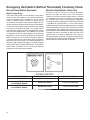
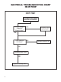
Emergency Heat Switch (Defrost Thermostat) Continuity Check
Electric Heat Switch Operation
Electric Heat Switch Check Out
(Heat Pumps Only)
The switch may be checked out with an ohmmeter.
Remove and label the three wires from the switch.
Terminal 2 is common and the contacts make to Terminal
3 on temperature rise and to Terminal 1 on temperature
fall. With the control set in the emergency heat position
continuity should be read between Terminal 2 and Terminal
1 regardless of coil temperature. As the control shaft is
rotated clockwise, through the adjustment range, continuity
will be read between Terminal 2 and Terminal 3, providing
the temperature of the capillary tube is above 25º (± 5%). If
the temperature at the capillary tube is above approximately
52 degrees it may be necessary to place the end of the
capillary tube in ice water to determine if the control is
sensing temperature changes. Should the control lose the
gas charge in the capillary tube it will fail to the electric heat
position and the compressor will not operate.
The electric heat switch is a dual function control and is
shown on the wiring diagram as a defrost thermostat.
It may be adjusted using a screwdriver. As the control
shaft is rotated counter clockwise a detent will be
encountered. Turning the control past the detent will lock
out the compressor and acts as an emergency heat switch.
Turning the control shaft clockwise will lower the change
over point for compressor operation. The control it self is
a double throw, single pole switch operated by a bellows
and a gas filled capillary tube. The capillary tube senses
a combination of outdoor coil temperature and outdoor air
temperature. As the combined temperatures reach a point
that the outdoor coil is iced, where heat pump operation
is no longer efficient, the control shuts off the compressor
and turns on the electric heat. At its lowest setting the cut
off point is approximately 25 degrees, the highest setting
is 52 degrees, with a 10 degree differential. It is possible,
under certain conditions, for the unit to cycle between
compressor and electric heat operation.
24
SWITCH POSITION
TEMPERATURE AT CAPILLARY
CONTINUITY READ
EMERGENCY HEAT
N/A
1 and 2 = Electric Heat
ANYWHERE IN
ADJUSTMENT RANGE
ABOVE SET POINT
2 and 3 = Compressor
ANYWHERE IN
ADJUSTMENT RANGE
BELOW SET POINT
1 and 2 = Electric Heat
Wiring Diagram Index
MODEL
DIAGRAM
PAGE
MODEL
DIAGRAM
PAGE
VEA09K00 RTA ................... 80004910 ...................28
VEA12K34RTG.................. 80004920 ...................32
VEA09K00RTB ................. 80004910 ...................28
VEA12K34RTH .................. 80004920 ...................32
VEA09K00RTE ................. 80004910 ...................28
VEA12K50RTA .................. 80004911....................30
VEA09K00RTG ................. 80004922 ...................34
VEA12K50RTB .................. 80004911....................30
VEA09K00RTH ................. 80004922 ...................34
VEA12K50RTE .................. 80004911....................30
VEA09K25 RTA ................ 80004911....................30
VEA12K50RTG.................. 80004920 ...................32
VEA09K25RTB ................. 80004911....................30
VEA12K50RTH .................. 80004920 ...................32
VEA09K25RTE ................. 80004911....................30
VEA18K00RTA .................. 80004910 ...................28
VEA09K25RTG ................. 80004923 ...................35
VEA18K00RTB .................. 80004910 ...................28
VEA09K25RTH ................. 80004923 ...................35
VEA18K00RTC .................. 80004910 ...................28
VEA09K34RTA.................. 80004911....................30
VEA18K00RTD.................. 80004910 ...................28
VEA09K34RTB ................. 80004911....................30
VEA18K00RTE .................. 80004910 ...................28
VEA09K34RTE ................. 80004911....................30
VEA18K00RTG ................. 80004919 ...................31
VEA09K34RTG ................. 80004923 ...................35
VEA18K00RTH.................. 80004919 ...................31
VEA09K34RTH ................. 80004923 ...................35
VEA18K25RTA .................. 80004911....................30
VEA09K50RTA.................. 80004911....................30
VEA18K25RTB .................. 80004911....................30
VEA09K50RTB ................. 80004911....................30
VEA18K25RTC.................. 80004911....................30
VEA09K50RTE ................. 80004911....................30
VEA18K25RTD ................. 80004911....................30
VEA09K50RTG ................. 80004923 ...................35
VEA18K25RTE .................. 80004911....................30
VEA09K50RTH ................. 80004923 ...................35
VEA18K25RTG ................. 80004920 ...................32
VEA12K00RTA .................. 80004910 ...................28
VEA18K25RTH ................. 80004920 ...................32
VEA12K00RTB .................. 80004910 ...................28
VEA18K34RTA .................. 80004911....................30
VEA12K00RTE .................. 80004910 ...................28
VEA18K34RTB .................. 80004911....................30
VEA12K00RTG.................. 80004919 ...................31
VEA18K34RTC .................. 80004911....................30
VEA12K00RTH.................. 80004919 ...................31
VEA18K34RTD.................. 80004911....................30
VEA12K25RTA .................. 80004911....................30
VEA18K34RTE .................. 80004911....................30
VEA12K25RTB .................. 80004911....................30
VEA18K34RTG ................. 80004920 ...................32
VEA12K25RTE .................. 80004911....................30
VEA18K34RTH.................. 80004920 ...................32
VEA12K25RTG ................. 80004920 ...................32
VEA18K50RTA .................. 80004911....................30
VEA12K25RTH.................. 80004920 ...................32
VEA18K50RTB .................. 80004911....................30
VEA12K34RTA .................. 80004911....................30
VEA18K50RTC .................. 80004911....................30
VEA12K34RTB .................. 80004911....................30
VEA18K50RTD.................. 80004911....................30
VEA12K34RTE .................. 80004911....................30
VEA18K50RTE .................. 80004911....................30
25
MODEL
DIAGRAM
PAGE
MODEL
DIAGRAM
PAGE
VEA18K50RTG ................. 80004920 ...................32
VHA12K34RTH ................. 80004921 ...................33
VEA18K50RTH.................. 80004920 ...................32
VHA12K50RTA .................. 80004912 ...................29
VEA24K00RTH ................. 80110500 ....................37
VHA12K50RTB .................. 80004912 ...................29
VEA24K10RTH ................. 80108800 ...................38
VHA12K50RTE .................. 80004912 ...................29
VEA24K25RTH ................. 80108800 ...................38
VHA12K50RTG ................. 80004921 ...................33
VEA24K34RTH ................. 80108800 ...................38
VHA12K50RTH ................. 80004921 ...................33
VEA24K50RTH ................. 80108800 ...................38
VHA18K25RTA .................. 80004912 ...................29
VEA24K75RTH ................. 80108800 ...................38
VHA18K25RTB.................. 80004912 ...................29
VHA09K25RTA ................. 800004912 .................29
VHA18K25RTC ................. 80004912 ...................29
VHA09K25RTB ................. 800004912 .................29
VHA18K25RTD ................. 80004912 ...................29
VHA09K25RTE ................. 800004912 .................29
VHA18K25RTE.................. 80004912 ...................29
VHA09K25RTG ................. 800004924 .................36
VHA18K25RTG ................. 80004921 ...................33
VHA09K25RTH ................. 800004924 .................36
VHA18K25RTH ................. 80004921 ...................33
VHA09K34RTA ................. 800004912 .................29
VHA18K34RTA .................. 80004912 ...................29
VHA09K34RTB ................. 800004912 .................29
VHA18K34RTB .................. 80004912 ...................29
VHA09K34RTE ................. 800004912 .................29
VHA18K34RTC.................. 80004912 ...................29
VHA09K34RTG ................. 800004924 .................36
VHA18K34RTD ................. 80004912 ...................29
VHA09K34RTH ................. 800004924 .................36
VHA18K34RTE .................. 80004912 ...................29
VHA09K50RTA ................. 800004912 .................29
VHA18K34RTG ................. 80004921 ...................33
VHA09K50RTB ................. 800004912 .................29
VHA18K34RTH ................. 80004921 ...................33
VHA09K50RTE ................. 800004912 .................29
VHA18K50RTA .................. 80004912 ...................29
VHA09K50RTG ................. 800004924 .................36
VHA18K50RTB.................. 80004912 ...................29
VHA09K50RTH ................. 800004924 .................36
VHA18K50RTC ................. 80004912 ...................29
VHA12K25RTA .................. 80004912 ...................29
VHA18K50RTD ................. 80004912 ...................29
VHA12K25RTB.................. 80004912 ...................29
VHA18K50RTE.................. 80004912 ...................29
VHA12K25RTE.................. 80004912 ...................29
VHA18K50RTG ................. 80004921 ...................33
VHA12K25RTG ................. 80004921 ...................33
VHA18K50RTH ................. 80004921 ...................33
VHA12K25RTH ................. 80004921 ...................33
VHA24K10RTH ................. 80110300 ....................39
VHA12K34RTA .................. 80004912 ...................29
VHA24K25RTH ................. 80110300 ....................39
VHA12K34RTB .................. 80004912 ...................29
VHA24K34RTH ................. 80110300 ....................39
VHA12K34RTE .................. 80004912 ...................29
VHA24K50RTH ................. 80110300 ....................39
VHA12K34RTG ................. 80004921 ...................33
VHA24K75RTH ................. 80110300 ....................39
26
27
(A - D Suffix only)
28
(A - D Suffix only)
29
(A - D Suffix only)
30
31
32
33
34
35
36
37
38
9-18 ELECTRICAL TROUBLESHOOTING CHART — COOLING
NO COOLING
Insure that Fuses
are good and/or that
Circuit Breakers are
On
O.K.
Set thermostat to
"Cool," move the Temp.
lever below the present
Room Temp.
O.K.
Compressor runs but
Fan doesn't
Fan runs but
Compressor doesn't
No
Yes
Yes
Nothing operates,
entire system
appears dead
Yes
No
Line voltage present
at the Transformer
Primary
Compressor and Fan
Motor should now
operate
Check Supply Circuit
for loose connections
or broken wiring
No
Problems indicated with
Control Transformer
No
Check Supply Circuit
for loose connections or
broken wiring
Yes
Yes
24 Volts at
Transformer
Secondary?
See Refrigerant Circuit
diagnosis if unit still is
not cooling properly
Turn Fan Switch of Room
Thermostat to "On"
position or jump "R" to
"G" at Terminal board
No
Yes
24 Volts present at
Cool Relay?
O.K.
Yes
Does Fan Motor operate
now?
No
Problems indicated with
Room Thermostat or
Control Wiring
No
24Volts at Coil
Terminals of Blower
Relay?
Yes
Problem indicated in
Control wiring and/or
Room Thermostat
No
Problem indicated in
Control Wiring and/
or Room Thermostat
Yes
Line Voltage
available at fan
speed switch
(on models so
equipped)
No
Problems indicated
in Blower Relay
Yes
Fan Motor operates,
but Compressor
doesn't
Is Line Voltage present
at Motor Leads?
No
Yes
Check Capacitor, is
Capacitor Good?
Check Fan
Speed Switch
(on models so equipped)
or Blower Relay on later
models
No
Is Locked Rotor
Voltage a minimum of
197 Volts?
Yes
Compressor and fan
motor should now
operate
Yes
See Refrigerant
Circuit Diagnosis if
unit still is not cooling
properly
Replace Capacitor
No
Replace Capacitor
and/or Start Assist
Device
Yes
Motor should run
Yes
Supply Circuit
problems, loose
Connections, or bad
Relays
No
No
Possible motor
problem indicated.
Check motor
thoroughly
No
Are Capacitor and (if
so equipped) Start
Assist good?
Yes
Allow ample time
for pressures to
equalize
No
Have System
Pressures Equalized?
Yes
Possible Compressor
problem indicated.
See Compressor
Checks
No
Compressor should
run
39
2-TON ELECTRICAL TROUBLESHOOTING CHART — Cooling
NO COOLING
Insure that Fuses
are good and/or that
Circuit Breakers are
On
O.K.
Set thermostat to
"Cool," move the Temp.
lever below the present
Room Temp.
O.K.
Compressor and outdoor
fan motor run but indoor
blower does not run
Indoor blower runs but
outdoor fan motor and
compressor do not run
No
Yes
Yes
Nothing operates,
entire system
appears dead
Yes
No
Line voltage present
at the Transformer
Primary
Compressor outdoor
fan motor and indoor
blower should now
operate
Check Supply Circuit
for loose connections
or broken wiring
No
Problems indicated with
Control Transformer
No
Check H.P. Switch is
so equipped
Yes
Yes
Turn Fan Switch of Room
Thermostat to "On"
position or jump "R" to
"G" at Terminal board
No
24 Volts at
Transformer
Secondary?
See Refrigerant Circuit
diagnosis if unit still is
not cooling properly
Yes
24 Volts present at
Cool Relay?
O.K.
Yes
Does indoor blower
now operate?
No
Check Supply Circuit
for loose connections or
broken wiring
No
24Volts at Coil
Terminals of Blower
Relay?
Yes
Problem indicated in
Control wiring and/or
Room Thermostat
No
Problem indicated in
Control Wiring and/
or Room Thermostat
No
Problems indicated with
Room Thermostat or
Control Wiring
Yes
Line Voltage
available at fan
speed switch
(on models so
equipped)
No
Problems indicated
in Blower Relay
Yes
Outdoor fan motor
operates, but compressor doesn’t
Is Line Voltage present
at Motor Leads?
No
Yes
Check Capacitor, is
Capacitor Good?
Check Fan
Speed Switch
(on models so equipped)
or Blower Relay on later
models
No
Is Locked Rotor
Voltage a minimum of
197 Volts?
Yes
Replace Capacitor
No
Replace Capacitor
and/or Start Assist
Device
Yes
Motor should run
Yes
Supply Circuit
problems, loose
Connections, or bad
Relays
No
Possible motor
problem indicated.
Check motor
thoroughly
No
Are Capacitor and (if
so equipped) Start
Assist good?
Yes
Allow ample time
for pressures to
equalize
No
Have System
Pressures Equalized?
Yes
Possible Compressor
problem indicated.
See Compressor
Checks
40
No
Compressor should
run
No
Compressor and
outdoor fan motor
should now operate
Yes
See Refrigerant
Circuit Diagnosis
if unit still is not
cooling properly
TROUBLESHOOTING CHART — COOLING
REFRIGERANT SYSTEM DIAGNOSIS COOLING
Low Suction Pressure
High Suction Pressure
Low Head Pressure
High Head Pressure
Low Load Conditions
High Load Conditions
Low Load Conditions
High Load Conditions
Low Air Flow Across
Indoor Coil
High Air Flow Across
Indoor Coil
Refrigerant System
Restriction
Low Air Flow Across
Outdoor Coil
Refrigerant System
Restriction
Reversing Valve not
Fully Seated
Reversing Valve not
Fully Seated
Overcharged
Undercharged
Overcharged
Undercharged
in System
Moisture in System
Defective Compressor
Defective Compressor
Non-Condensables (air)
TROUBLESHOOTING CHART — HEATING
REFRIGERANT SYSTEM DIAGNOSIS HEATING
Low Suction Pressure
High Suction Pressure
Low Head Pressure
High Head Pressure
Low Air Flow Across
Outdoor Coil
Outdoor Ambient Too High
for Operation in Heating
Refrigerant System
Restriction
Outdoor Ambient Too High
For Operation In Heating
Refrigerant System
Restriction
Reversing Valve not
Fully Seated
Reversing Valve not
Fully Seated
Low Air Flow Across
Indoor Coil
Undercharged
Overcharged
Undercharged
Overcharged
Moisture in System
Defective Compressor
Defective Compressor
Non-Condensables (air)
in System
41
ELECTRICAL TROUBLESHOOTING CHART
HEAT PUMP
HEAT PUMP
SYSTEM COOLS WHEN
HEATING IS DESIRED.
Is Line Voltage
Present at
Solenoid Valve?
NO
Is Selector Switch
set for Heat?
YES
Is the Solenoid
Coil Good?
NO
YES
Reversing Valve Stuck
YES
Replace Reversing Valve
42
Replace Solenoid Coil
43
Use Factory Certified Parts.
FRIEDRICH AIR CONDITIONING CO.
Post Office Box 1540 · San Antonio, Texas 78295-1540
4200 N. Pan Am Expressway · San Antonio, Texas 78218-5212
(210) 357-4400 · FAX (210) 357-4480
www.friedrich.com
Printed in the U.S.A.
VPSERVMN (4-05)