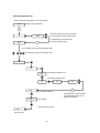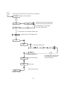
1
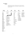
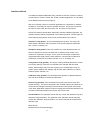
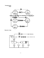
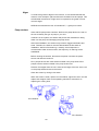
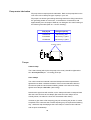
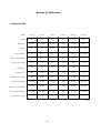
NESLAB
CFT series
using TC-200 controller
NESLAB Manual P/N U00320
Rev. 22 June 1999
Service manual
NESLAB online
Product Service Information, Electronic Catalog,
Applications Notes, MSDS Forms, e-mail.
Call our bulletin board system
(603)427-2490
Contact us for free FirstClass® access software.
Specify Macintosh or Windows.
Voice Info: (800) 4-NESLAB
Visit our Web page at:
http://www.neslabinc.com
service resources
NESLAB
ONLINE
NESLAB ONLINE is your source for online service data,
including service bulletins, manuals, refrigerant charging
information, calibration instructions, and more for all catalog
units. You can browse the same library our Technical Support
representatives use - and this is available 24 hours a day, 7 days a
week. Obtain the access software, FirstClass Client, from sources
on the next page or from us. Then use it to connect to (603) 4272490 by modem.
FirstClass Client for
FirstClass Client for
3 . x
'9 5
NESLAB
OFFLINE
NESLAB OFFLINE is a cd-rom which contains all the content of
NESLAB ONLINE as of Jan. 1 1998. This is ideal if you have no
modem capability. The cd-rom works on both Macintosh and
Windows computers. It also includes FirstClass Client.
NESLAB OFFLINE cd-rom
The
EVAPORATOR
The EVAPORATOR is our service newsletter. It contains service
bulletins and information of interest to anyone who maintains
NESLAB equipment.
Name
mail:
NESLAB ONLINE
PO Box 1178
Portsmouth NH 03802-1178
Company
Address
fax: (603) 430-6387
City
e-mail:
[email protected]
State / Province
Zip / Postal code
e-mail address (optional)
subscription to The Evaporator
Sources for FirstClass Client for
Macintosh
Sources for FirstClass Client for
Windows
3.5" disk:
3.5" disk:
Obtain from NESLAB. The Mac client is
published on red disks. If you have a CD
drive, use one of the CD sources below as
they carry a later version. Installation is not
required - you can run the application right
off the floppy disk.
Obtain from NESLAB. The Windows client is
published on blue disks. It works on Windows 3.x
or Windows 95. If you have a CD-ROM drive,
use the CD-ROM (below) instead as it carries a
later version.
CD-ROM:
CD-ROM:
NESLAB OFFLINE 1998 cd-rom
NESLAB OFFLINE 1998 cd-rom
cd-rom companion to the magazine:
MacAddict, Issue #1, Sep. 1996
go to: Shareware / Connectivity / FirstClass
Client.
cd-rom companion to the magazine:
MacAddict, Issue #13, Sep. 1997
go to: Shareware / Communications /
FirstClass Client.
cd-rom companion to the book:
Macintosh Revelations by Ken Maki
go to: Telecom / BBS Software / FirstClass
Client.
Any cd-rom shareware/software collection
from BMUG (Berkeley Mac Users Group)
N
Download from NESLAB ONLINE:
Download from NESLAB ONLINE:
Go to Conferences / Software / Mac
Go to Conferences / Software / Windows
Download from America Online:
Download from America Online:
Keyword: SoftArc
Keyword: Softarc
Download from Compuserve:
Download from Compuserve:
TWEUROPA / Teletools / FCMAC.ZIP
PCBBS / BBS programs / FCC300.EXE
Download from World Wide Web:
Download from World Wide Web:
http: // www.softarc.com
http: // www.softarc.com
.
.
4
Contents
Section I:
Safety
Warnings ........................................................................................................................................................................ 6
Section II:
General
information
After sale support ........................................................................................................................................................... 7
Other resources ............................................................................................................................................................. 7
Decoding part numbers ................................................................................................................................................. 8
Interface defined ............................................................................................................................................................ 9
Navigating loops ........................................................................................................................................................... 10
Operator’s loop ............................................................................................................................................................ 10
Setup loop .................................................................................................................................................................... 11
Calibration loop ............................................................................................................................................................ 13
Configuration loop ........................................................................................................................................................ 14
Service loop ................................................................................................................................................................. 15
Displaying software version ......................................................................................................................................... 16
Section III:
Service
Troubleshooting ........................................................................................................................................................... 17
Microprocessor replacement ....................................................................................................................................... 20
Error codes .................................................................................................................................................................. 21
Section IV:
Adjustments
Factory defaults ............................................................................................................................................................
Restoring factory defaults ............................................................................................................................................
Field calibration ............................................................................................................................................................
Hot gas valve ................................................................................................................................................................
22
22
23
26
Service contracts .........................................................................................................................................................
Reservoir ......................................................................................................................................................................
Cleaning .......................................................................................................................................................................
Algae ............................................................................................................................................................................
Pump strainer ...............................................................................................................................................................
Pump motor lubrication ................................................................................................................................................
Torque values ...............................................................................................................................................................
27
27
27
28
28
29
29
Refrigerant data ...........................................................................................................................................................
MSDS form: R-134a refrigerant ...................................................................................................................................
MSDS form: R-22 refrigerant .......................................................................................................................................
Service bulletin U00336: CFT75 - solenoid valve change ...........................................................................................
Service bulletin U00349: CFT33 - check capacitor wiring ...........................................................................................
Year 2000 statement ....................................................................................................................................................
30
31
33
38
39
40
Section V:
Preventive
maintenance
Section VI:
Reference
5
Section I: Safety
Warnings
Make sure you read and understand all instructions and safety precautions listed
in this manual before installing or operating your unit. If you have any questions
concerning the operation of your unit or the information in this manual, contact
our Sales Department (see After-sale Support).
Performance of installation, operation, or maintenance procedures other than
those described in this manual may result in a hazardous situation and may void
the manufacturer’s warranty.
Observe all warning labels. Never remove warning labels.
Never operate damaged or leaking equipment.
Never operate the unit without cooling fluid in the reservoir.
Always turn off the unit and disconnect the power source before performing any
service or maintenance procedures, or before moving the unit.
Always empty the reservoir before moving the unit.
Never operate equipment with damaged line cords.
Refer service and repairs to a qualified technician.
In addition to the safety warnings listed above, warnings are posted throughout
the manual. These warnings are designated by an exclamation mark inside an
equilateral triangle with text highlighted in bold print. Read and follow these
important instructions. Failure to observe these instructions can result in permanent damage to the unit, significant property damage, or personal injury or death.
The lightning flash with arrow symbol, within an equilateral triangle, is intended to
alert the user to the presence of non-insulated “dangerous voltage” within the
unit’s enclosure. The voltage may be of significant magnitude to constitute a risk
of electrical shock.
6
Section II: General information
After Sale Support
NESLAB is committed to customer service both during and after the sale. If you
have questions concerning the operation of your unit, contact our Sales Department. If your unit fails to operate properly, or if you have questions concerning
spare parts or service contracts, contact our Service Department. Before calling,
please obtain the following information from the unit’s serial number label:
part number
serial number
Other resources
The Instruction and Operation Manual for the CFT series is PN U00362.
Pump systems are covered in a separate service manual.
For MD pumps, obtain service manual 000877.
For PD pumps, obtain service manual 000878.
7
Decoding part
numbers
NESLAB identifies units using a 12-digit part number. To decode the part number, split up the digits as shown in the chart below. This will define what characteristics the unit has.
000
0
unit family
condenser
128 EX111
129 EX211
130 EX221
131 EX411
132 EX511
134 RTE111
135 RTE211
136 RTE221
137 EX111
138 EX211
139 EX221
140 EX411
141 EX511
157 RTE140
167 RTE111
168 RTE211
169 RTE221
171 RTE140,LT50
331 CFT25A
332 CFT33A
333 CFT75A
334 CFT25, R12
335 CFT33, R12
336 CFT75, R12
337 CFT150,FAC200
347 CFT25, R22
348 CFT33, R22
349 CFT75, R22
386 HX75, R22
387 HX100, R22
388 HX150, R22
389 HX200, R22
390 HX300, R22
391 HX500, R22
392 HX750, R22
393 CFT25, R134a
394 CFT33, R134a
395 CFT75, R134a
396 CFT300,FAC400
397 CFT500
398 CFT750
400 CFT100
607 CFT50
608 CFT75
612 RTE microprocessor
613 CFT200
0 Not applicable
1 Air cooled
2 Water cooled
00
01
02
03
04
05
06
07
08
09
10
11
12
13
15
16
17
20
21
22
23
99
00
00
pump/head
electrical
00
01
02
03
04
05
06
07
08
09
10
11
12
15
16
17
18
19
20
21
22
23
24
25
26
28
None
100v / 50Hz / 1ø
100v 60Hz (no longer used)
115v / 60Hz / 1ø
208-230v / 60Hz / 1ø
208-230v / 60Hz / 3ø
220-240v / 50Hz / 1ø
220-240v / 50Hz / 3ø
Slave
440-480v / 60Hz / 3ø
380-415v / 50Hz / 3ø (4 wire)
100v / 50-60Hz
100-115v / 50-60Hz
200v / 50Hz / 1ø
200v / 50-60Hz
Dual rated:
200v / 50Hz / 1ø
200-230v / 60Hz / 1ø
208v / 60Hz / 3ø (5 wire)
415v / 50Hz / 3ø
380-415v / 50Hz / 3ø (5 wire)
200-240v / 50-60Hz /1ø
380-480v / 50-60Hz / 3ø (4 wire)
Special
29
30
31
99
8
No pump
CP25
CP55
PD1
PD2
CP75
TU1
TU5
TU6
TU7
TU8
SS PD1
SS PD2
MD30
CP20
G1
F Pump, 1 Stage
F Pump, 2 Stage
Z Pump
F Immersion head
R Immersion head
FV Immersion head
H Pump
Dual PD1
Dual PD2
was PD3,
now unassigned
CP100
TU9
TU3
Special
00
controller
01
02
03
04
05
06
07
08
09
10
11
12
13
14
15
16
17
Analog
Digital, non bath
Series II
Programmable
Basic
Cryotrol
Digital, bath
UL approved
UL approved
plus interlocks
UL approved
plus alarm pkg.
Microprocessor
Digital remote
(HX1000, HX2000)
Fisher standard digital
Controller I (TC100)
Controller II (TC200)
Controller III (TC300)
Controller IV (TC400)
00
catalog
Once upon a time 00
indicated a standard
catalog unit, and 01
and up indicated the
presence of
customizing options
and/or accessories.
That distinction is no
longer used and these
digits have no special
significance any more.
Interface defined
This statement defines NESLAB’s policy towards access and contents of various
control loops for TC200, TC300, and TC400 controller applications. It is provided
by the Measurement and Control group.
With an increasing number of controller applications it is important to maintain
consistency in the way we code our operator interface. The goal is to minimize
the effort to code, build, test, document, use, and service our products.
Unless the customer specification specifically requests a different approach, the
operator interface will be programmed in the following manner. Private loops are
those requiring a proprietary access code, as described in this manual.
Operator’s loop (public): This is the default power-up loop. This loop is for
basic display information and the location of the process setpoint adjustment,
flow 1, flow 2, resistivity, etc.
Setup/tune loop (public): This loop contains any other adjustments the customer is expected to access. Consider this an advanced user’s loop. If the
customer is expected to change it, then it goes here. Example: Proportionalintegral-derivative (PID) values, alarm setpoints, communication enable and
parameters, remote sensor enable, selection of °F or °C display, etc.
Configuration loop (private): This loop is used by NESLAB production to enter
any factory settings. These are not intended to be changed after the initial
setting. Some designs may not have anything in the Configuration Loop. Example: injector setpoint and settings, high and low span, interlocks or cutouts,
50/60 Hz power selection, etc.
Calibration loop (private): This loop allows the operator to calibrate temperature and other variables to reference instruments.
Service loop (private): This is intended for service personnel to aid in field
trouble-shooting. The service loop allows the controller inputs and outputs to be
monitored and changed for testing of the electrical control system and components. Each application needs an unique one page service sheet that defines the
controller inputs/outputs before the service loop can be used.
Documentation: The operators manual will only contain the operator’s loop and
setup/tune loop information. The appendix of the operators manual may also
contain the calibration loop information. The service manual will contain all the
different loops.
Mark Sinclair
Measurement and Control Manager
9
Navigating the
loops
hold
OPERATOR’S
LOOP
NEXT
SETUP
LOOP
TUNE
XX C
PUBLIC LOOPS
PRIVATE LOOPS
hold
CALIBRATION
LOOP
hold
CONFIGURATION
LOOP
CAL
SERVICE
LOOP
CONF
hold
SERV
Operator’s loop
10
Setup loop - part 1
11
Setup loop - part 2
12
Calibration loop
13
Configuration loop
14
Service loop
15
Displaying
software version
The TC-200 controller has a function which will show the installed software
version number on the unit’s digital display.
For example, for a unit with software version 000550.45B:
1. Unit is running normally and displaying temperature.
2. Press and hold the NO key for at least 10 seconds.
The display will show the digits to the left of the decimal (for example): 0550
(note the two leading zeros are not shown).
3. Press the NEXT key.
The display will show the digits to the right of the decimal (for example): 45
4. Press the NEXT key.
The display will show the revision letter, as its equivalent number, with A=1, B=2,
etc. (for example): 2
5. Press the NEXT key.
The digits shown may be disregarded.
6. Press the NEXT key.
The display returns to normal, displaying temperature.
16
Section III. Service
Troubleshooting
Unit will not start
Check the line cord, make sure it is plugged in.
Check the voltage of the power source. Make sure it is within the rated
voltage of the unit, ±10%.
Check that the Power Switch/Circuit Breaker has not tripped.
Check the setting on the optional High Temperature Cutout.
CFT-300 units are equipped with high and low pressure switches. If either
switch activates the unit will shut down. Once the cause has been
determined you have to manually reset the switch. The switches are located
behind the rear panel, see the operation manual.
Unit will not circulate fluid
Check the reservoir level. Fill, if necessary.
Make sure the pump has been purged.
Check the pressure gauge (units with PD pumps). If the reading is 60
psig, check the instrument being cooled for restrictions in the cooling line.
Check the pump strainer (units with PD pumps). A clogged strainer can
starve the pump.
Inadequate temperature control
If the temperature continues to rise, make sure the heat load of the
instrument being cooled does not exceed the rated specification, see
the operating manual for specifications.
Make sure the air intake and discharge are not impeded and the ambient
temperature does not exceed +35°C.
Make sure the condenser is free of dust and debris.
If the compressor short-cycles (a clicking sound), check the line voltage.
It should be within the 10% of the specified voltage. Wait 5 minutes
before restarting the unit.
17
Symptom
Possible cause
Repair
Compressor will
not start - no hum
1. Line disconnect switch open
2. Line fuse (if any) removed or blown
3. Overload protector tripped
4. Wiring improper or loose
1. Close start or disconnect switch
2. Replace fuse
3. Allow compressor to cool
4. Check against wiring diagram
Compressor will
not start - hums
but trips on overload
protector
1. Improperly wired
2. Low line voltage
3. Start capacitor defective
4. Relay failing to close
5. Compressor motor has winding
open or shorted
6. Compressor mechanical failure
7. Liquid refrigerant in compressor
1. Check against wiring diagram
2. Determine reason and correct
3. Determine reason and replace
4. Determine reason and correct,
replace if necessary
5. Replace compressor
6. Replace compressor
7. Add crankcase heater and/or accumulator
1. Improperly wired
2. Low line voltage
3. Relay failing to open
1. Check against wiring diagram
2. Determine reason and correct
3. Determine reason and correct,
replace if necessary
4. Determine reason and replace
5. Check discharge shut-off valve,
possible overcharge, or insufficient
cooling on condenser
6. Replace compressor
7. Replace compressor
Compressor starts,
but does not switch
off start winding
4. Run capacitor defective
5. Excessive discharge pressure
6. Compressor motor has winding
open or shorted
7. Compressor mechanical failure
8. Compressor motor has a winding shorted
1. Check wiring diagram. Check for
added fan motors, pumps, etc.,
connected to wrong side of protector
2. Determine reason and correct.
3. Check current, replace protector
4. Determine reason and replace
5. Check ventilation, restrictions in
recirculating fluid path, restrictions
in refrigeration system
6. Check for possibility of misapplication.
Use stronger unit
7. Check refrigerant charge (fix leak),
add if necessary
8. Replace compressor
1. Overload protector
2. High temperature cutout, if so equipped
1. See entire section above
2. Heat load too high, fluid flow too low
3. High pressure cutout due to:
a. insufficient air or water supply
b. overcharge
c. air in system
3a. Check air or water supply to condenser
3b. Reduce refrigerant charge
3c. Purge
1. Additional current passing through
overload protector
Compressor starts
and runs, but short
cycles on overload
protector
2. Low line voltage, or unbalanced if
three-phase
3. Overload protector defective
4. Run capacitor defective
5. Excessive discharge pressure
6. Suction pressure too high
7. Compressor too hot, return gas hot
Unit runs but
continually stops
and restarts
4. Low pressure cutout due to:
a. liquid line solenoid leaking
b. compressor valve leak
c. undercharge
d. restriction in expansion device
18
4a. Replace
4b. Replace
4c. Fix leak, add refrigerant
4d. Replace device
Symptom
Possible cause
Repair
Unit operates
long or
continuously
1. Shortage of refrigerant
2. Control contacts stuck closed
3. Refrigerated fluid has excessive
load or poor insulation
4. System inadequate to handle load
5. Evaporator coil iced
6. Restriction in refrigeration system
7. Dirty condenser
8. Air filter (if any) dirty
1. Fix leak, add charge
2. Clean contacts or replace
3. Determine fault and correct
4. Replace with larger system
5. Defrost
6. Determine location and remove
7. Clean condenser
8. Clean on replace
Start capacitor
open, shorted,
or blown
1. Relay contacts not operating properly
2. Prolonged operation on start cycle due to:
a. low voltage to unit
b. improper relay
c. starting load too high
3. Excessive short cycling
4. Improper capacitor
1. Clean contacts, replace relay if needed
2a. Determine reason and correct
2b. Replace
2c. Correct
3. Determine reason and correct
4. Determine correct size and replace
Run capacitor
open, shorted,
or blown
1. Improper capacitor
2. Excessively high line voltage
(110% of rated maximum)
1. Determine correct size and replace
2. Determine reason and correct
Relay defective
or burned out
1. Incorrect relay
2. Incorrect mounting angle
3. Line voltage too high or too low
4. Excessive short cycling
5. Relay being influenced by loose
vibrating mounting
6. Incorrect run capacitor
1. Check and replace
2. Remount relay in correct position
3. Determine reason and correct
4. Determine reason and correct
5. Remount rigidly
6. Replace with proper capacitor
Recirculating
fluid temperature
too high
1. Control setpoint too high
2. Expansion valve too small
3. Evaporator too small
4. Inadequate air circulation
through condenser
1. Reset setpoint.
2. Use larger valve.
3. Add surface area or replace
4. Improve air movement
Suction line
frosted or
sweating
1. Expansion valve passing excess
refrigerant or is oversized
2. Expansion valve stuck open
3. Overcharge of refrigerant
1. Readjust valve or replace with
smaller valve
2. Clean valve of foreign particles,
replace if necessary
3. Correct charge
Liquid line
frosted or
sweating
1. Restriction in drier or strainer
2. Liquid shut off (king valve)
(if so equipped) partially closed
1. Replace part
2. Open valve fully
Unit noisy
1. Loose parts or mountings
2. Tubing rattle
3. Bent fan blade causing vibration
4. Fan motor bearings worn
1. Find and tighten
2. Reform to be free of contact
3. Replace blade
4. Replace motor
19
Microprocessor
replacement
1. WARNING: Physically disconnect unit from line voltage.
2. Use proper Electro-Static Discharge (ESD) protection procedures. A wrist
strap is mandatory, at a minimum. NESLAB is not responsible for replacement of
integrated circuits damaged by ESD.
3. A Plastic Leaded Chip Carrier (PLCC) extraction tool is required.
4. Remove wrapper of unit.
5. Remove the cover from the control box. On CFT-25, 33, and 75 there are four
screws. On CFT-150 and larger, there are only two screws.
6. CFT-25, 33, and 75 only: The control box assembly must be pulled outside
the case to allow access room. Remove the two nuts that hold the control box
assembly to the case. Tip the control box assembly out of the hole in the case.
Remove the secondary cover (the one with all the strain reliefs mounted to it).
Note: On CFT-150 and larger, there is adequate access room. The control box
assembly may remain mounted to the case.
7. Observe the pin orientation of the old microprocessor chip. Remove it using
the PLCC extraction tool. Install the new microprocessor chip, making sure the
pin 1 designation on the microprocessor chip (a dimple in the middle of one side)
and the socket (generally a triangle pointer on the socket or the circuit board)
align. DO NOT USE THE ORIENTATION OF THE PAPER LABEL FOR ALIGNMENT. THE PAPER LABEL ORIENTATION IS ARBITRARY.
arrow
slots for
extraction
tool
dot
empty socket
chip
chip in socket
8. Reassemble the unit and all covers.
9. Plug unit in and turn it on. Error messages will appear. Press ENTER/NEXT
after each error message until the temperature display appears.
10. The unit is now operational, but calibration has been lost. Calibrate unit per
instructions in this manual.
20
Error codes
On power up:
These messages will be displayed on the controller. The controller will wait for
someone to press the next/enter key. Once the “next/enter” key is pressed the
controller will restore factory defaults and begin to run. For example if “Err1”
is on the controller display at power up, this indicates the internal ram is messed
up.
Er01 - Ram test failure
Er02 - Keypad failure, shorted keypad
Er03 - Critical checksum failure, will restore all factory defaults.
Er04- Non-Critical checksum failure, will restore 1/2 of factory values, keeps
calibration, PID, restore setpoint
Unusual Hardware Conditions
These errors will flash on the display and cannot be cleared. These are internal
controller problems.
Er04 thru Er15 - Interrupt errors during runtime
Functional/ Machine errors
These are the runtime/ logic errors these errors will clear themselves once the
problem disappears.
Er16 - Bad calibration data - recalibrate controller
Er19 - Low temperature alarm
Er21 - High temperature alarm
Er22 - High tank temperature
Er23 - Shorted RTD2
Er24 - Open RTD2
Er25 - Shorted RTD1
Er26 - Open RTD1
Er31 - Low level fault
ADD - Low level alarm
21
Section IV. Adjustments
Factory defaults
Cool PID values:
Pro
20
Int
0.5
Der
0
Heat PID values:
Pro
5
Int
0.5
Der
0
Alarms
Hi temp
Lo temp
90
-20
Span
CFT25/33/75 standard temp
CFT25/33/75 high temp
CFT25/33/75 low temp
CFT150/300 standard temp
CFT150/300 high temp
CFT150/300 low temp
Lo limit 5
Lo limit 5
Lo limit -15
Hi limit 30
Hi limit 85
Hi limit 30
Lo limit 5
Lo limit 5
Lo limit -15
Hi limit 35
Hi limit 85
Hi limit 35
Cool cycle 15
Restoring factory
defaults
This procedure will restore all controller values to the factory default settings
(which vary by product).
1. Begin in the Operator’s loop, displaying temperature as normal.
2. Hold NO, and while holding it, press YES, YES, YES. This should result in the
Calibration Loop, with the display indicating “CaL”.
3. Hold NO, and while holding it, press YES, YES, YES. This should result in the
Configuration Loop, with the display indicating “ConF”.
4. Hold NO, and then press and hold NEXT/ENTER for seven seconds minimum. This should result in the display indicating “reSt” (meaning RESTORE).
5. Press YES. The controller will restore the factory default settings and return to
the Operator’s Loop.
22
Field calibration
The unit is calibrated at the factory. Changing any values will nullify temperature
indications. The calibration loop should only be used by qualified factory or
service personnel. Improper calibration can affect product temperature measurements.
Requirements
Temperature calibration is performed at two different temperatures.
Calibration will be valid at and between those temperatures.
The unit must run at both of these temperatures in turn to be calibrated.
A reference thermometer is required.
Choosing calibration points
Decide what two temperatures you wish to use as calibration points. The temperatures chosen must be within the operating range of the unit (5° - 30°C),
achievable, and measurable using a reference thermometer. Calibration will be
most valid when the two points are as separated as possible, i.e. 5°C and 30°C.
If the unit is only operated at one temperature (for example, 22°C), you may
wish to optimize calibration at that point by choosing closer calibration points;
such as 20° and 24°C.
Procedure - overview
The general procedure consists of:
1. From operator’s loop, adjust setpoint to lower calibration point
2. Allow unit to achieve the lower calibration point.
3. Go to calibration loop, enter the reference thermometer value.
4. Go to operator’s loop, adjust setpoint to higher calibration point
5. Allow unit to achieve the higher calibration point.
6. Go to calibration loop, enter the reference thermometer value.
Note: The calibration points are independent.
The higher point may be set first if more convenient.
The step-by-step procedure follows.
23
Begin in the Operator’s Loop
Immerse a reference thermometer in the circulating fluid.
XXXC
Display current temperature.
NEXT
SP
XXXC
XXXC
Controller is ready to receive a new setpoint.
This will become the lower calibration point.
NEXT
Use YES/NO keys to increment digits
to the lower calibration point.
Unit now begins to go to the lower calibration point.
Use private key to go to the Calibration Loop.
hold
CAL
RTD1
Decline higher calibration point
R1H
Accept lower calibration point
R1L
RTD2
STOR
R1L
XXXC
NEXT
Decline RTD2 calibration
Save changes
Return to Operator’s Loop
XXXC
go to next page
24
Use YES/NO keys to increment digits
to the temperature shown on the
reference thermometer.
from
previous
page
Ensure the reference thermometer is immersed in the circulating fluid.
XXXC
Display current temperature.
NEXT
SP
XXXC
XXXC
Controller is ready to receive a new setpoint.
This will become the higher calibration point.
NEXT
Use YES/NO keys to increment digits
to the higher calibration point.
Unit now begins to go to the higher calibration point.
Use private key to go to the Calibration Loop.
hold
CAL
RTD1
Accept higher calibration point
R1H
R1H
R1L
XXXC
NEXT
Decline lower calibration point
RTD2
Decline RTD2 calibration
STOR
Save changes
Return to Operator’s Loop
XXXC
calibration is complete
25
Use YES/NO keys to increment digits
to the temperature shown on the
reference thermometer.
Hot gas valve
The hot gas valve is adjusted as follows.
WARNING: Disconnect unit from line voltage.
1. Attach refrigerant gauges and verify that the refrigerant charge is approximately correct.
2. Start unit and allow it to stabilize.
3. Turn unit setpoint up so unit remains in the heat/idle cycle.
4. Observe suction pressure gauge.
5. Compare reading of gauge to that in the refrigerant data table.
6. Adjust valve, if necessary, to comform to the table.
7. Turn unit off.
WARNING: Disconnect unit from line voltage.
8. Remove refrigerant gauges.
26
Section V. Preventive maintenance
For personal safety and equipment reliability, the following procedure
should only be performed by a qualified technician. Contact our
Service Department for assistance (see After-sale Support).
Service contracts
NESLAB offers on-site Service Contracts that are designed to provide
extended life and minimal down-time for your unit. For more information,
contact our Service Department (see After-sale Support).
Draining the
reservoir
The CFT-300 is equipped with a ½ inch FPT DRAIN fitting located on the
rear of the unit.
To drain the CFT-25 to CFT-150 reservoirs we recommend the use of a
wet/dry vacuum. Remove the reservoir plug and carefully insert the wet/dry
vacuum so as not to damage the cooling coils. NOTE: Tilting the unit more
than 45° may allow compressor oil to seep into the suction line.
Cleaning
Reservoir
Periodically inspect the fluid inside the reservoir. If cleaning is necessary,
flush the reservoir with a cleaning fluid compatible with the circulating
system and the cooling fluid.
The cooling fluid should be replaced periodically. When operating at low
temperatures, the concentration of water in the cooling fluid will increase
over time, leading to a loss of cooling capacity.
Before changing the cooling fluid, raise the operating temperature of the unit
to de-ice the cooling coils. Refer to the operating manual for instructions on
replacing the cooling fluid.
Condenser
For proper operation, the unit needs to pull substantial amounts of air
through a condenser. A build up of dust or debris on the fins of the
condenser will lead to a loss of cooling capacity.
The lower front of the unit has a one-piece grille assembly. Gently pry the
assembly off with a flathead screwdriver. Use care not to scratch the paint.
Periodic vacuuming of the condenser fins is necessary. The frequency of
cleaning depends on the operating environment. We recommend a visual
inspection of the condenser be made monthly after initial installation. After
several months, the frequency of cleaning will be established.
27
Algae
To restrict the growth of algae in the reservoir, it is recommended that the
reservoir cover be kept in place and that all circulation lines be opaque. This
will eliminate the entrance of light which is required for the growth of most
common algae.
NESLAB recommends the use of Chloramine-T, 1 gram per 3.5 liters.
Pump strainer
Units with PD pumps have a strainer. Refer to the pump label on the rear of
the unit to identify the type of pump in your unit.
If debris is in the system, the strainer will prevent the material from being
drawn into the pump and damaging the pump vanes.
After initial installation, the strainer may become clogged with debris and
scale. Therefore, the strainer must be cleaned after the first week of
installation. After this first cleaning, a monthly visual inspection is
recommended. After several months, the frequency of cleaning will be
established.
Before cleaning the strainer, disconnect the power cord from the power
source and drain the reservoir.
PD-1 pumps have a wire mesh strainer located in the pump head. PD-2
pumps have the strainer located in the pump suction line.
Remove the wrapper from the unit. Unscrew the larger of the two acorn nuts
on the pump head and remove the screen.
Clean the screen by rinsing it with water.
When the screen is clean, replace it in the strainer, tighten the acorn nut and
replace the wrapper. Refer to the operating manual for instructions on
replacing the cooling fluid.
PD-2 Strainer
PD-1 Strainer
28
Pump motor lubrication
PD pump motors require periodic lubrication. Refer to the pump label on the
rear of the unit to identify the type of pump in your unit.
PD pumps use sleeve type bearings with large reservoirs. Oiling instructions
are generally posted on each motor. In the absence of instructions, add
approximately 30 to 35 drops of SAE 20 non-detergent oil to each bearing on
the following schedule (SAE 20 = 142 CS viscosity):
Duty Cycle
Oiling Frequency
Continuous
Once every year
Intermittent
Once every 2 years
Occasional
Once every 5 years
Fill Holes (Typical)
Torque
V-band clamp
The V-band clamp (which joins the pump to the motor) should be tightened to
15 - 30 inch-pounds (85 - 170 cm/kg) of torque.
Hose clamps
The unit's internal and external hoses and clamps should be inspected and
tightened on at least a semiannual basis. If the unit uses standard clear reinforced hose (with the reinforcement webbing visible in the wall of the hose),
tighten hose clamps to 50 in/lbs (280 cm/kg).
Note that this type hose will cold-flow, so the clamps will need to retorqued later
after the hose conforms to the clamps. (Be aware the hose clamps do not
actually loosen, but rather the hose O.D. decreases under them!)
It is best to give them a final torqueing just prior to leaving the job site. It is wise
to explain to the customer that a further torqueing may be required the following
day - and that a drip developing at the hose clamp is a result of this cold-flow
and not poor workmanship.
29
Section VI. Reference
refrigerant data
Model
CFT-25
CFT-33
CFT-75
CFT-150
CFT-300
CFT-300
Pump
any
any
any
any
CP55,TU5,TU6
PD2
R-134a
R-134a
R-134a
R-22
R-22
R22
Amount
4 oz
7 oz
13.75 oz
29 oz
8.5-9.5 lbs
8.5-9.5 lbs
Amount (metric)
115 g
200 g
390 g
822 g
3.8-4.3 kg
3.8-4.3 kg
Hot gas setting (PSIG)
5
5
5
25
25
25
Hot gas setting (kPa)
35
35
35
172
172
172
Ambient (°F)
68
68
68
68
74
74
Fluid temp (°C)
20
20
20
20
20
20
25-28
42-45
37-41
70
85-90
88-94
Suction pressure (kPa)
172-193
290-310
255-282
480
585-620
605-650
Discharge pressure (PSIG)
145-160
180-200
170-185
270
265-280
265-280
1000-1100
1240-1380
1175-1275
1860
1827-1930
1827-1930
4.0
2.5
4.6
2.8
6.4
6.4
Refrigerant
Suction pressure (PSIG)
Discharge pressure (kPa)
Speed check (°C/min)
6024
30
material safety
data sheet (MSDS)
A Material Safety Data Sheet (MSDS) is designed to provide both workers and emergency personnel with
the proper procedures for handling or working with that substance. MSDS will include information such as
physical data (melting point, boiling point, flash point etc.), toxicity, health effects, first aid, reactivity,
storage, disposal, protective equipment, and spill/leak procedures. These are of particular use if a spill or
other accident occurs. This Material Safety Data Sheets is provided as a public service. It was gathered from
a variety of sources. Neither NESLAB Instruments, Inc., nor any of its agents are liable for
the accuracy, or inaccuracy, of the Material Safety Data Sheet. You assume the liability for the use of
any part of this Material Safety Data Sheet.
R-134a refrigerant
DUPONT E I — SUVA COLD-MP, SUVA 134A
MATERIAL SAFETY DATA SHEET
FSC: 6830
NIIN: 00D003276
Manufacturer’s CAGE: 02348
Part No. Indicator: A
Part Number/Trade Name: SUVA COLD-MP, SUVA 134A
===========================================================================
General Information
===========================================================================
Company’s Name: DU PONT E I DE NEMOURS & CO
Company’s Street: 1007 MARKET ST
Company’s City: WILMINGTON
Company’s State: DE
Company’s Country: US
Company’s Zip Code: 19899
Company’s Emerg Ph #: 800-441-7515/800-441-3637
Company’s Info Ph #: 800-441-7515
Record No. For Safety Entry: 001
Tot Safety Entries This Stk#: 001
Status: SE
Date MSDS Prepared: 12MAR94
Safety Data Review Date: 14JUL94
Supply Item Manager: CX
MSDS Preparer’s Name: ENGIN. & PRODUCT SAFETY
Preparer’s Company: DUPONT CHEMICALS
Preparer’s St Or P. O. Box: POB 80709, CHESTNUT RUN
Preparer’s City: WILMINGTON
Preparer’s State: DE
Preparer’s Zip Code: 19880-0709
MSDS Serial Number: BTRLM
Specification Number: NOT KNOWN
Hazard Characteristic Code: G3
Unit Of Issue: UK
Unit Of Issue Container Qty: UNKNOWN
Type Of Container: UNKNOWN
Net Unit Weight: UNKNOWN
===========================================================================
Ingredients/Identity Information
===========================================================================
Proprietary: NO
Ingredient: 1,1,1,2-TETRAFLUOROETHANE
Ingredient Sequence Number: 01
Percent: 100
NIOSH (RTECS) Number: 1008365TE
CAS Number: 811-97-2
OSHA PEL: NOT ESTABLISHED
ACGIH TLV: NOT ESTABLISHED
Other Recommended Limit: NONE RECOMMENDED
===========================================================================
Physical/Chemical Characteristics
===========================================================================
Appearance And Odor: LIQUEFIED GAS, SLIGHT ETHEREAL ODOR, COLORLESS.
Boiling Point: -16F,-27C
Melting Point: N/A
Vapor Pressure (MM Hg/70 F): 96PSIA@25C
Vapor Density (Air=1): 3.60 @25C
Specific Gravity: N/A
Decomposition Temperature: N/A
Solubility In Water: 0.15WT% @25C/14.7PSI
Percent Volatiles By Volume: 100
pH: N/A
===========================================================================
Fire and Explosion Hazard Data
===========================================================================
Flash Point: WILL NOT BURN
31
Lower Explosive Limit: N/A
Upper Explosive Limit: N/A
Extinguishing Media: AS APPROPRIATE FOR COMBUSTIBLES IN AREA.
Special Fire Fighting Proc: COOL CYLINDERS W/WATER SPRAY. SELF-CONTAINED
BREATHING APPARATUS MAY BE REQUIRED IF CYLINDERS RUPTURE OR RELEASE UNDER
FIRE CONDITIONS.
Unusual Fire And Expl Hazrds: CYLINDERS MAY RUPTURE UNDER FIRE CONDITONS.
DECOMPO MAY OCCUR.EXPERIMENTAL DATA HAVE REPORTED COMBUST OF MATL IN
PRESENCE OF CERTAIN CONCEN OF CHLORINE.SEE SUPPL
===========================================================================
Reactivity Data
===========================================================================
Stability: YES
Cond To Avoid (Stability): AVOID OPEN FLAMES AND HIGH TEMPERATURE. ALSO
GLOWING METAL SURFACES.
Materials To Avoid: ALKALI OR ALKALINE EARTH METALS-POWDERED ALUMINUM,
ZINC, BERYLIUM, ETC. CERTAIN CONCENTRATIONS OF CHLORINE.
Hazardous Decomp Products: DECOMPOSES @ HI TEMP FORMING HYDROFLUORIC ACID
AND POSSIBLY CARBONYL FLUORIDE.
Hazardous Poly Occur: NO
Conditions To Avoid (Poly): NOT RELEVANT.
===========================================================================
Health Hazard Data
===========================================================================
LD50-LC50 Mixture: DUPONT’S 1000PPM, 8 & 12 HR TWA.
Route Of Entry - Inhalation: YES
Route Of Entry - Skin: YES
Route Of Entry - Ingestion: NO
Health Haz Acute And Chronic: INHAL OF HI CONCEN OF VAPOR IS HARMFUL & MAY
CAUSE HEART IRREGULARITIES, UNCONSCIOUSNESS OR DEATH. VAPOR REDUCES OXYGEN
AVAILABLE FOR BREATHING & IS HEAVIER THAN AIR. LIQ CONTACT CAN CAUSE
FROSTBITE.
Carcinogenicity - NTP: NO
Carcinogenicity - IARC: NO
Carcinogenicity - OSHA: NO
Explanation Carcinogenicity: PER MSDS:NONE OF COMPONENTS PRESENT IN MATL @
CONCEN = OR < 0.1% ARE LISTED BY IARC,NTP, OSHA OR ACGIH AS A CARCINOGEN.
Signs/Symptoms Of Overexp: OVEREXOSURE BY INHAL TO VERY HI CONCEN MAY
CAUSE TEMP ALTERATION OF THE HEART’S ELECTRICAL ACTIVITY WITH IRREGULAR
PULSE, PALPITATIONS, OR INADEQUATE CIRCULATION. SKIN CONTACT WITH THE
LIQUID MAY CAUSE FROSTBITE.
Med Cond Aggravated By Exp: INDIVIDUALS WITH PRE-EXISTING DISEASES OF THE
CENTRAL NERVOUS OR CARDIOVASCULAR SYSTEM MAY HAVE INCREASED SUSCEPTIBILITY
TO THE TOXICITY OF EXCESSIVE EXPOSURES.
Emergency/First Aid Proc: INHAL:IMMED REMOVE TO FRESH AIR.KEEP PERSON
CALM.NOT BREATH GIVE ARTIF RESP.BREATH DIFFI GIVE OXY.CALL DR. SKIN:IMMED
FLUSH W/LOTS OF H2O FOR @ LEAST 15MINS.REMOVE CONTAM CLOTH/SHOE.CALL DR.
TREAT FOR FROSTBITE IF NECESSARY BY GENTLY WARMING AFFECTED AREA.EYE:IMMED
FLUSH W/LOTS OF H2O FOR @ LEAST 15MINS.CALL DR. DR:BECAUSE POSSIBLE
DISTRUBANCES OF CARDIAC RHYTHM USE CATECHOLAMINE DRUGS CAUTIOUSLY.
===========================================================================
Precautions for Safe Handling and Use
===========================================================================
Steps If Matl Released/Spill: REVIEW FIRE FIGHTING MEASURES BEFORE
PROCEEDING W/CLEANUP.USE APPROPRIATE PPE DURING CLEANUP.VENTI
AREAESPECIALLY LOW OR ENCLOSED PLACES WHERE HEAVY VAPORS COLLECT.REMOVE
OPEN FLAMES.USE SCBA IF LG SPILL OR LEAK OCCURS.
Neutralizing Agent: NOT SPECIFIED BY MANUFACTURER.
Waste Disposal Method: CONTAMINATED HFC-134A CAN BE RECOVERED BY
DISTILLATION OR REMOVED TO A PERMITTED WASTE DISPOSAL FACILITY. COMPLY WITH
LOCAL, STATE AND FEDERAL REGULATIONS.
Precautions-Handling/Storing: STORE IN CLEAN, DRY AREA. DO NOT HEAT ABOVE
52C. USE W/SUFFICIENT VENTILATION TO KEEP EMPLOYEE EXPOSURE BELOW
RECOMMENDED LIMITS.
Other Precautions: HFC-134A SHOULD NOT BE MIXED W/AIR FOR LEAK TESTING OR
USEDS W/AIR FOR ANY OTHER PURPOSE ABOVE ATMOSPHERIC PRESSURE. SEE FIRE &
EXPLOSION DATA & SUPPLEMENTAL SECS. CONTACT W/CHLORINE OR OTHER STRONG
OXIDIZING AGENTS SHOULD ALSO BE AVOIDED.
===========================================================================
Control Measures
===========================================================================
Respiratory Protection: UNDER NORMAL MANUFACTURING CONDITIONS NO
RESPIRATORY PROTECTION IS REQUIRED WHEN USING THIS PRODUCT. SELF-CONTAINED
BREATHING APPARATUS (SCBA) IS REQUIRED IF A LARGE RELEASE OCCURS.
Ventilation: NORMAL VENTILATION FOR STANDARD MANUFACTURING PROCEDURES IS
GENERALLY ADEQUATE.
Protective Gloves: IMPERVIOUS GLOVES.
Eye Protection: CHEM SPLASH GOGGLES.
Other Protective Equipment: NONE SPECIFIED BY MANUFACTURER.
Work Hygienic Practices: WASH CONTAMINATED CLOTHING/SHOE PRIOR TO REUSE.
Suppl. Safety & Health Data: MATL NOT FLAMM @ AMBIENT TEMP & ATM
32
PRESSURE.TESTS HAVE SHOWN COMBUSTIBLE @ PRESSURE AS LOW AS 5.5 PSIG @ 177C
WHEN MIXED W/AIR @ CONCEN OF GENERALLY MORE THAN 60 VOLUME % AIR.AT LOWER
TEMP,HIGHER PRESSURE ARE REQUIRED FOR COMBUSTIBILITY. DO NOT USE IN MED
APPLICATINS INVOLVING PERMANENT IMPLANTATION IN THE HUMAN BODY.
===========================================================================
Transportation Data
===========================================================================
Trans Data Review Date: 94195
DOT PSN Code: DQQ
DOT Proper Shipping Name: COMPRESSED GASES, N.O.S. *
DOT Class: 2.2
DOT ID Number: UN1956
DOT Label: NONFLAMMABLE GAS
IMO PSN Code: EQH
IMO Proper Shipping Name: COMPRESSED GAS, N.O.S. *
IMO Regulations Page Number: 2125
IMO UN Number: 1956
IMO UN Class: 2(2.2)
IMO Subsidiary Risk Label: IATA PSN Code: HDO
IATA UN ID Number: 1956
IATA Proper Shipping Name: COMPRESSED GAS, N.O.S. * *
IATA UN Class: 2.2
IATA Label: NON-FLAMMABLE GAS
AFI PSN Code: HDO
AFI Prop. Shipping Name: COMPRESSED GAS, N.O.S.
AFI Class: 2.2
AFI ID Number: UN1956
AFI Label: NON-FLAMMABLE GAS
AFI Basic Pac Ref: 6-6,6-8,6-10
N.O.S. Shipping Name: COMPRESSED OR LIQUIFIED GAS, N.O.S
(TETRAFLUOROETHANE).
R-22 refrigerant
E I DUPONT — FREON 22 - MONOCHLORODIFLUOROM
MATERIAL SAFETY DATA SHEET
NSN: 6830013825105
Manufacturer’s CAGE: 18873
Part No. Indicator: A
Part Number/Trade Name: FREON 22
===========================================================================
General Information
===========================================================================
Item Name: MONOCHLORODIFLUOROM
Company’s Name: E I DUPONT DE NEMOURS & CO
Company’s Street: 1007 MARKET ST
Company’s City: WILMINGTON
Company’s State: DE
Company’s Country: US
Company’s Zip Code: 19898
Company’s Emerg Ph #: 800-441-3637;800-424-9300(CHEMTREC)
Company’s Info Ph #: 800-441-9442
Record No. For Safety Entry: 001
Tot Safety Entries This Stk#: 003
Status: SMJ
Date MSDS Prepared: 13AUG92
Safety Data Review Date: 15MAR95
MSDS Serial Number: BXBSX
===========================================================================
Ingredients/Identity Information
===========================================================================
Proprietary: NO
Ingredient: METHANE, CHLORODIFLUORO-; (CHLORODIFLUOROMETHANE) (SARA 313)
(CERCLA)
Ingredient Sequence Number: 01
Percent: 100
NIOSH (RTECS) Number: PA6390000
CAS Number: 75-45-6
OSHA PEL: 1000 PPM
ACGIH TLV: 1000 PPM
——————————————————Proprietary: NO
Ingredient: SUP DAT: IN THE PRESENCE OF CERTAIN CONCENTRATIONS OF
CHLORINE.
Ingredient Sequence Number: 02
NIOSH (RTECS) Number: 9999999ZZ
OSHA PEL: NOT APPLICABLE
ACGIH TLV: NOT APPLICABLE
33
——————————————————Proprietary: NO
Ingredient: VENT: VENTILATION SHOULD BE USED IN LOW OR ENCLOSED PLACES.
Ingredient Sequence Number: 03
NIOSH (RTECS) Number: 9999999ZZ
OSHA PEL: NOT APPLICABLE
ACGIH TLV: NOT APPLICABLE
——————————————————Proprietary: NO
Ingredient: OTHER PREC: “FREON 22” SHOULD NOT BE MIXED W/AIR FOR LEAK
TESTING. IN GEN, IT SHOULD NOT BE USED/ALLOWED TO BE (ING 5)
Ingredient Sequence Number: 04
NIOSH (RTECS) Number: 9999999ZZ
OSHA PEL: NOT APPLICABLE
ACGIH TLV: NOT APPLICABLE
——————————————————Proprietary: NO
Ingredient: ING 4: PRESENT W/HIGH CONCS OF AIR ABOVE ATMOSPHERIC PRESS.
CONT W/CHLORINE/OTHER STRONG OXIDIZING AGENTS SHOULD (ING 6)
Ingredient Sequence Number: 05
NIOSH (RTECS) Number: 9999999ZZ
OSHA PEL: NOT APPLICABLE
ACGIH TLV: NOT APPLICABLE
——————————————————Proprietary: NO
Ingredient: ING 5: ALSO BE AVOIDED.
Ingredient Sequence Number: 06
NIOSH (RTECS) Number: 9999999ZZ
OSHA PEL: NOT APPLICABLE
ACGIH TLV: NOT APPLICABLE
——————————————————Proprietary: NO
Ingredient: EFTS OF OVEREXP: OVEREXP. SKIN CONT W/LIQUID MAY CAUSE FRSTBT.
INDIVIDUALS W/PREEXISTING DISEASES OF CNS OR (ING 8)
Ingredient Sequence Number: 07
NIOSH (RTECS) Number: 9999999ZZ
OSHA PEL: NOT APPLICABLE
ACGIH TLV: NOT APPLICABLE
——————————————————Proprietary: NO
Ingredient: ING 7: CARDIOVASCULAR SYSTEM MAY HAVE INCREASED SUSCEPTIBILITY
TO TOXICITY OF EXCESSIVE EXPOSURES.
Ingredient Sequence Number: 08
NIOSH (RTECS) Number: 9999999ZZ
OSHA PEL: NOT APPLICABLE
ACGIH TLV: NOT APPLICABLE
Other Recommended Limit: YN/KNONE RECOMMENDED
——————————————————Proprietary: NO
Ingredient: HLTH HAZ: RANGING FROM 5% TO 70% INCLUDE EFTS ON CNS, LIVER,
LUNGS, KIDNEYS, SPLEEN; CARDIAC SENSIT; DECREASED (ING 10)
Ingredient Sequence Number: 09
NIOSH (RTECS) Number: 9999999ZZ
OSHA PEL: NOT APPLICABLE
ACGIH TLV: NOT APPLICABLE
——————————————————Proprietary: NO
Ingredient: ING 9: BODY WT GAIN, & PARTIAL ANESTH. IN CHRONIC INHAL
STUDIES FC-22 PRODUCED A SM, BUT STATISTICALLY (ING 11)
Ingredient Sequence Number: 10
NIOSH (RTECS) Number: 9999999ZZ
OSHA PEL: NOT APPLICABLE
ACGIH TLV: NOT APPLICABLE
——————————————————Proprietary: NO
Ingredient: ING 10: SIGNIFICANT, INCREASE OF TUMORS IN MALE RATS, BUT NOT
FEMALE RATS OR MALE/FEMALE MICE AT A CONC OF (ING 12)
Ingredient Sequence Number: 11
NIOSH (RTECS) Number: 9999999ZZ
OSHA PEL: NOT APPLICABLE
ACGIH TLV: NOT APPLICABLE
——————————————————Proprietary: NO
Ingredient: ING 11: 50000 PPM (V/V). FC-22 WAS MUTAGENIC IN BACTERIAL CELL
CULTURES BUT NOT MAMMALIAN CELL CULTURES, & WAS (ING 13)
Ingredient Sequence Number: 12
NIOSH (RTECS) Number: 9999999ZZ
OSHA PEL: NOT APPLICABLE
ACGIH TLV: NOT APPLICABLE
——————————————————Proprietary: NO
34
Ingredient: ING 12: NOT MUTAGENIC IN WHOLE ANIMAL ESSAYS. A SLIGHT, BUT
SIGNIFICANT INCREASE IN DEVEL TOXICITY (EYE (ING 14)
Ingredient Sequence Number: 13
NIOSH (RTECS) Number: 9999999ZZ
OSHA PEL: NOT APPLICABLE
ACGIH TLV: NOT APPLICABLE
——————————————————Proprietary: NO
Ingredient: ING 13: MALFORMATIONS, DECR FETAL WTS) HAS BEEN OBSERVED IN
OFFSPRING OF RATS EXPOSED TO HIGH CONCS (50000 PPM) (ING 15)
Ingredient Sequence Number: 14
NIOSH (RTECS) Number: 9999999ZZ
OSHA PEL: NOT APPLICABLE
ACGIH TLV: NOT APPLICABLE
——————————————————Proprietary: NO
Ingredient: ING 14: OF FC-22, CONC WHICH WAS ALSO MATERNALLY TOXIC. BASED
ON FINDINGS, FC-22 IS NOT CONSIDERED A UNIQUE HAZ (ING 16)
Ingredient Sequence Number: 15
NIOSH (RTECS) Number: 9999999ZZ
OSHA PEL: NOT APPLICABLE
ACGIH TLV: NOT APPLICABLE
——————————————————Proprietary: NO
Ingredient: ING 15: TO CONCEPTUS & POSES NO CARCIN HAZ WHEN EXPOSURES ARE
BELOW TLV. CHLOROFLUOROCARBON (CFC) MATLS HAVE (ING 17)
Ingredient Sequence Number: 16
NIOSH (RTECS) Number: 9999999ZZ
OSHA PEL: NOT APPLICABLE
ACGIH TLV: NOT APPLICABLE
——————————————————Proprietary: NO
Ingredient: ING 16: PRODUCED SENSIT OF MYOCARDIUM TO EPINEPHRINE IN LAB
ANIMALS & COULD HAVE A SIMILAR EFT IN HUMANS. (ING 18)
Ingredient Sequence Number: 17
NIOSH (RTECS) Number: 9999999ZZ
OSHA PEL: NOT APPLICABLE
ACGIH TLV: NOT APPLICABLE
——————————————————Proprietary: NO
Ingredient: ING 17: ADRENOMIMETICS (E.G., EPINEPHRINE) MAY BE
CONTRAINDICATED EXCEPT FOR LIFE-SUSTAINING USES IN HUMANS (ING 19)
Ingredient Sequence Number: 18
NIOSH (RTECS) Number: 9999999ZZ
OSHA PEL: NOT APPLICABLE
ACGIH TLV: NOT APPLICABLE
——————————————————Proprietary: NO
Ingredient: ING 18: ACUTELY OR CHRONICALLY EXPOSED TO CFC’S.
Ingredient Sequence Number: 19
NIOSH (RTECS) Number: 9999999ZZ
OSHA PEL: NOT APPLICABLE
ACGIH TLV: NOT APPLICABLE
——————————————————Proprietary: NO
Ingredient: % VOLAT: 100 (WT).
Ingredient Sequence Number: 20
NIOSH (RTECS) Number: 9999999ZZ
OSHA PEL: NOT APPLICABLE
ACGIH TLV: NOT APPLICABLE
===========================================================================
Physical/Chemical Characteristics
===========================================================================
Appearance And Odor: CLEAR, COLORLESS LIQUEFIED GAS WITH SLIGHT ETHEREAL
ODOR
Boiling Point: -41F,-41C
Vapor Pressure (MM Hg/70 F): 151 PSIG
Vapor Density (Air=1): 3.03
Specific Gravity: 1.194
Evaporation Rate And Ref: >1
Solubility In Water: 0.30 WT % @ 25C
Percent Volatiles By Volume: ING 20
pH: NEUT
===========================================================================
Fire and Explosion Hazard Data
===========================================================================
Flash Point: NONE
Flash Point Method: TOC
Extinguishing Media: AS APPROPRIATE FOR COMBUSTIBLES IN AREA.
EXTINGUISHANT FOR OTHER BURNING MATERIAL IN AREA IS SUFFICIENT TO STOP
35
BURNING.
Special Fire Fighting Proc: WEAR NIOSH/MSHA APPRVD PRESSURE DEMAND SCBA &
FULL PROT EQUIP (FP N). USE WATER SPRAY/FOG TO COOL CONTAINERS.
Unusual Fire And Expl Hazrds: THERMAL DECOMP PRODS MAY INCLUDE CHLORIDES,
FLUORIDES & PHOSGENE (FP N). OTHER BURNING MATLS MAY CAUSE HCFC 22 TO BURN
WEAKLY. CHLORODIFLUOROMETHANE (SUP DAT)
===========================================================================
Reactivity Data
===========================================================================
Stability: YES
Cond To Avoid (Stability): AVOID OPEN FLAMES AND HIGH TEMPERATURES.
Materials To Avoid: ALKALI OR ALKALINE EARTH METALS (POWDERED AL, ZN, BE,
ETC.).
Hazardous Decomp Products: HIGH TEMPS (OPEN FLAMES, GLOWING METAL SURFS,
ETC.) FORMING HYDROCHLORIC & HYDROFLUORIC ACIDS, & POSS CARBONYL (SUP DAT)
Hazardous Poly Occur: NO
Conditions To Avoid (Poly): NOT RELEVANT.
===========================================================================
Health Hazard Data
===========================================================================
LD50-LC50 Mixture: NONE SPECIFIED BY MANUFACTURER.
Route Of Entry - Inhalation: YES
Route Of Entry - Skin: YES
Route Of Entry - Ingestion: NO
Health Haz Acute And Chronic: INHAL OF HIGH CONCS OF VAP IS HARMFUL & MAY
CAUSE IRREGULARITIES, UNCONSCIOUSNESS/DEATH. INTENTIONAL MISUSE/DELIBERATE
INHAL MAY CAUSE DEATH WITHOUT WARNING. VAP REDUCES OXYGEN AVAILABLE FOR
BRTHG & IS HVR/AIR. LIQUID CONT CAN CAUSE FRSTBT. ANIMAL DATA: TOXICITY
DESCRIBED IN ANIMALS EXPOSED BY INHAL TO CONCS (ING 9)
Carcinogenicity - NTP: NO
Carcinogenicity - IARC: NO
Carcinogenicity - OSHA: NO
Explanation Carcinogenicity: NOT RELEVANT.
Signs/Symptoms Of Overexp: OVEREXP TO VAPS BY INHAL MAY INCLUDE TEMPORARY
NERVS SYS DEPRESS W/ANESTH EFTS SUCH AS DIZZ, HDCH, CONFUSN, INCOORD, &
LOSS OF CONSCIOUSNESS. HIGHER EXPOS TO VAPS MAY CAUSE TEMPORARY ALTERATION
OF HEART’S ELEC ACTIVITY W/IRREGULAR PULSE, PALPITATIONS/ INADEQUATE
CIRCULATION. FATALITY MAY OCCUR FROM GROSS (ING 7)
Med Cond Aggravated By Exp: BECAUSE OF POSSIBLE DISTURBANCES OF CARDIAC
RHYTHM, CATECHOLAMINE DRUGS, SUCH AS EPINEPHRINE, SHOULD ONLY BE CONSIDERED
AS A LAST RESORT IN LIFE-THREATENING EMERGENCIES.
Emergency/First Aid Proc: INHAL: IF LGE CONCS ARE INHALED, IMMED REMOVE TO
FRESH AIR. KEEP PERS CALM. IF NOT BRTHG, GIVE ARTF RESP. IF BRTHG IS
DIFFICULT, GIVE OXYGEN. CALL MD. SKIN CONT: FLUSH W/WATER FOR 15 MIN. TREAT
FOR FROSTBT IF NEC BY GENTLY WARMING AFFECTED AREA. IF IRRIT IS PRESENT,
CALL MD. EYES: IMMED FLUSH W/PLENTY OF WATER FOR AT LEAST 15 MIN. CALL MD.
INGEST: NOT CONSIDERED A POTENTIAL ROUTE OF EXPOSURE.
===========================================================================
Precautions for Safe Handling and Use
===========================================================================
Steps If Matl Released/Spill: NOTE: REVIEW FIRE & EXPLOS HAZ & SFTY PREC
BEFORE PROCEEDING W/CLEAN UP. USE APPROP PERSONAL PROT EQUIP DURING CLEAN
UP. VENT AREA, ESPECIALLY LOW/ENCLOSED PLACES WHERE HEAVY VAPS MIGHT
COLLECT. REMOVE OPEN FLAMES. USE SCBA FOR LGE SPILLS/RELEASES.
Neutralizing Agent: NONE SPECIFIED BY MANUFACTURER.
Waste Disposal Method: COMPLY WITH FEDERAL, STATE, AND LOCAL REGULATIONS.
RECLAIM BY DISTILLATION OR REMOVE TO A PERMITTED WASTE DISPOSAL.
Precautions-Handling/Storing: STORE IN CLEAN, DRY AREA. DO NOT HEAT ABOVE
52C (125F).
Other Precautions: NO SMKNG IN AREA OF USE. DO NOT USE IN GEN VICIN OF ARC
WELDING, OPEN FLAMES/HOT SURFS. HEAT &/UV RADIA MAY CAUSE FORM OF
CHLORIDES, FLUORIDES &/PHOSGENE (FP N). USE W/SUFFICIENT VENT TO KEEP
EMPLOYEE EXPOS BELOW RECOMMENDED LIMITS. (ING 4)
===========================================================================
Control Measures
===========================================================================
Respiratory Protection: UNDER NORMAL MANUFACTURING CONDITIONS, NO
RESPIRATORY PROTECTION IS REQUIRED WHEN USING THIS PRODUCT. USE NIOSH/MSHA
APPROVED SCBA WHEN A LARGE RELEASE OCCURS.
Ventilation: NORM VENT FOR STANDARD MFG PROC IS GEN ADEQ. LOC EXHAUST
SHOULD BE USED WHEN LARGE AMOUNTS ARE RELEASED. MECH (ING 3)
Protective Gloves: IMPERVIOUS GLOVES (FP N).
Eye Protection: ANSI APPRVD CHEM WORKERS GOGGS(FP N).
Other Protective Equipment: EMERGENCY EYEWASH & DELUGE SHOWER MEETING ANSI
DESIGN CRITERIA (FP N).
Work Hygienic Practices: NONE SPECIFIED BY MANUFACTURER.
Suppl. Safety & Health Data: HAZ DECOMP PROD: HALIDES, PHOSGENE (FP N).
EXPLO HAZ: IS NOT FLAM AT AMBIENT TEMPS & ATMOSPHERIC PRESS. HOWEVER IT HAS
BEEN SHOWN IN TESTS TO BE COMBUST AT PRESS AS LOW AS 60 PSIG AT AMBIENT
TEMP WHEN MIXED W/AIR AT CONCS OF 65 VOL & AIR. EXPTL DATA HAVE ALSO BEEN
REPORTED WHICH INDICATE COMBUST OF “FREON” 22 (ING 2)
36
===========================================================================
Transportation Data
===========================================================================
Trans Data Review Date: 95254
DOT PSN Code: IIC
DOT Proper Shipping Name: LIQUEFIED GASES
DOT Class: 2.2
DOT ID Number: UN1058
DOT Label: NONFLAMMABLE GAS
IMO PSN Code: IZR
IMO Proper Shipping Name: LIQUEFIED GASES,NON-FLAMMABLE,CHARGED WITH
NITROGEN,CARBON DIOXIDE OR AIR
IMO Regulations Page Number: 2155
IMO UN Number: 1058
IMO UN Class: 2(2.2)
IMO Subsidiary Risk Label: IATA PSN Code: PDL
IATA UN ID Number: 1058
IATA Proper Shipping Name: LIQUEFIED GASES
IATA UN Class: 2.2
IATA Label: NON-FLAMMABLE GAS
AFI PSN Code: PDL
AFI Prop. Shipping Name: LIQUEFIED GASES
AFI Class: 2.2
AFI ID Number: UN1058
AFI Label: NON-FLAMMABLE GAS
AFI Basic Pac Ref: 6-6,6-8
===========================================================================
Disposal Data
===========================================================================
===========================================================================
Label Data
===========================================================================
Label Required: YES
Technical Review Date: 16MAR95
Label Date: 16MAR95
Label Status: G
Common Name: FREON 22
Chronic Hazard: NO
Signal Word: WARNING!
Acute Health Hazard-Slight: X
Contact Hazard-Moderate: X
Fire Hazard-None: X
Reactivity Hazard-None: X
Special Hazard Precautions: ACUTE: INHALATION OF VAPORS MAY CONTRIBUTE TO
THE OCCURRENCE OF IRREGULAR HEART BEAT (FP N). CONTACT WITH LIQUID MAY
NONE SPECIFIED BY MANUFACTURER.
Protect Eye: Y
Protect Skin: Y
Protect Respiratory: Y
Label Name: E I DUPONT DE NEMOURS & CO
Label Street: 1007 MARKET ST
Label City: WILMINGTON
Label State: DE
Label Zip Code: 19898
Label Country: US
Label Emergency Number: 800-441-3637;800-424-9300(CHEMTREC)
=======================================================================
URL for this msds http://siri.org. If you wish to change, add to, or
delete information in this archive please sent updates to [email protected].
37
Service bulletin
U00336
30 Sep. 1998
CFT75: solenoid valve change
1. What units are affected?
model:
CFT 75 R134A ONLY (not R22 or R12)
part numbers:
395xxxxxxxxx
serial numbers:
this change occurs at serial number 198223000
date of manufacture:
this change occurs August 11, 1998
2. What is the problem/symptom?
The unit may runaway cold, even though the controller is calling for heating.
3. What is the cause?
The installed liquid line solenoid valve (PN 009475 - type XUP) is not optimum
for this application.
4. What is the fix?
The solenoid valve is replaced by a different one (PN 009741 - type XWG).
5. Should we fix any existing units (rework or recall units in the field)?
It is not necessary to service any units that operate correctly. If a unit exhibits
this symptom, the valve should be replaced with the new one. The coil is the
same and may be reused.
6. How do I get replacement parts or more information?
Consult NESLAB Technical Service.
7. Need more information?
Current service information is available 24 hours a day on NESLAB ONLINE.
Service information is available on the NESLAB OFFLINE 1998 cd-rom.
Service manual 000877 is available for CFT75 units using traditional (“Banks”)
controllers with a controller code of 01 or 02 (the controller code is the ninth and
tenth digits of the 12-digit unit part number). This manual is available on paper,
on cd-rom, and online. Service manual U00320 is available for CFT75 units
using the newer TC200 controllers with a controller code of 15 (the controller
code is the ninth and tenth digits of the 12-digit unit part number). This manual is
available on paper, or online.
Refer to PCO (Product Change Order) 12173.
Test sheets are available on microfiche at all NESLAB offices.
38
Service bulletin
U00349
18 May 1999
1. What units are affected?
model:
CFT-33
part numbers:
394106031501 394106031502 394106031503
394106031504 394106041501 394106041502
394106041503 394106041504 394106041505
394106041506 394106121501 394106991501
394106991502
serial numbers (approximate range): 196270001 to 199130001
date of manufacture: from late 1996 to May 1999
2. What is the problem/symptom?
When main power is applied the compressor will not start and the compressor
motor overload quickly trips. The start capacitor will appear to be shorted when
checked with an ohmmeter.
3. What is the cause?
Wires may have been incorrectly attached to the start capacitor by the condensing unit manufacturer so that the capacitor is shorted. Actual short is between
the wire terminal and the end cap of the bleeder resistor. A shorted capacitor can
not participate in the compressor start cycle and as a result the compressor
motor may not start.
bleeder resistor
possible short
wrong
right
4. What is the fix?
If capacitor is wired incorrectly, disconnect from line voltage and rewire start
capacitor as indicated. Replace bleeder resistor if the enamel is damaged. Unit
should now start normally.
5. Should we fix any existing units (rework or recall units in the field)?
All units returned for servicing should be checked for correct capacitor wiring.
Units found to be incorrectly wired should be reworked as shown.
6. Who can I call for help?
Our Technical service group is ready to help you sort out issues
involving product performance.
39
Year 2000
statement
NESLAB Instruments, Inc.
P.O. Box 1178 Portsmouth, NH 03802-1178 800/258-0830 FAX (603 436-8411)
Revised 18 May 1999
Subject: Y2K Year 2000 Policy Statement
NESLAB Instruments Inc. and the Year 2000. NESLAB Instruments Inc.
recognizes the importance of providing our customers with products that will
continue to function correctly during the Year 2000 and beyond. NESLAB is also
committed to communicating to its customers its status with respect to Year
2000 compliance.
Definition. NESLAB Instruments has adopted the following definition of Year
2000 compliance as set forth by the British Standards Institution in DISC
PD2000-1 A Definition of Year 2000 Conformity Requirements (available on the
Internet at http://www.bsi.org.uk/disc/year2000.html), with the qualification that
the upper limit for compliance is the year 2035:
Year 2000 conformity shall mean that neither performance nor functionality is
affected by dates prior to, during, and after the year 2000. In particular:
Rule 1: No value for current date will cause any interruption in operation.
Rule 2: Date-based functionality must behave consistently for dates prior to,
during, and after year 2000.
Rule 3: In all interfaces and data storage, the century in any date must be
specified either explicitly or by unambiguous algorithms or inferencing rules.
Rule 4: Year 2000 must be recognized as a leap year.
Our Products. It is our goal that our customers can continue to use our Products during and after the Year 2000. NESLAB Instruments has carried out a
review of its products with respect to Year 2000 compliance.
There are no current NESLAB products which incorporate clock or calendar
functions. Therefore, we believe all of our current products to be Year 2000
compliant.
Additional information about NESLAB Instruments’ products can be found at
our website (http://www.neslabinc.com).
40
Internal Business Systems. NESLAB has carried out a review of its products
and its internal systems with respect to Year 2000 compliance.
NESLAB houses an IBM AS/400 system that runs MAPICS XA R3 MRP
software. This software package is fully Year 2000 compliant. NESLAB also
utilizes Windows 95 and other Microsoft products on the desktop; all of these
software products are also Year 2000 compliant. In addition, NESLAB will be
performing internal testing to further ensure Year 2000 compliance of these
systems.
In addition, NESLAB Instruments is contacting its key vendors/suppliers to
assess their Year 2000 readiness.
Summary
In summary, NESLAB Instruments, Inc. believes that its products and its
internal business systems are currently Year 2000 compliant.
Customer Commitment. NESLAB Instruments recognizes the importance of
this issue to our customers. If you have additional questions, please contact Mr.
Mike Pratt of our technical support group.
Nothing in this statement is intended to modify rights and obligations under
any agreement or to create any new rights or obligations between NESLAB
Instruments and our customers.
Sincerely,
James R. Allen
Vice President Finance, Systems & Administration
* Mike Pratt: (603) 430-2245, [email protected]
41
US Headquarters
NESLAB Instruments, Inc.
P.O. Box 1178
Portsmouth, NH 03802-1178
(800) 258-0830
(603) 436-9444
Fax: (603) 436-8411
West Coast
32970 Alvarado/Niles Road
Suite 708
Union City, CA 94587
(800) 423-7831
(510) 429-1890
Fax: (510) 429-1898
Texas and South Central
States
8711 Burnet Road
Suite F69
Austin, TX 78757-7065
(512) 459-2167
Fax: (512) 459-1731
Canada
11 Hamilton Crescent
Georgetown, Ontario L7G 5J4
(905) 702-0656
Fax: (905) 702-0629
European Headquarters
The Netherlands
NESLAB Instruments Europa B.V.
Meerenakkerplein 31
5652 BJ
Eindhoven
The Netherlands
31 40-2300456
Fax: 31 40-2549485
United Kingdom
93-96 Chadwick Road
Astmoor, Runcorn, Cheshire
WA71PR UK
44 (019) 28562655
Fax: 44 (019) 28562656
Germany
Industriering Ost 66
D-47906 Kempen
Phone number: 49 2152/1417-30
Fax number: 49 2152/1417-55
France
70, rue Berthie Albrecht
94784 Vitry sur Seine cedex
011 331 43 91 17 00
Fax: 011 331 43 91 17 01
Main Service Center
The NESLAB Main Service Center is open 8:00 am to 5:00 pm (Eastern Time), Monday
through Friday.
NESLAB Instruments, Inc.
P.O. Box 1178
Portsmouth, NH 03802-1178
Phone: (800) 258-0830 or (603) 436-9444
Fax: (603) 436-8411