1
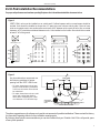
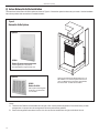
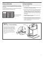
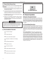
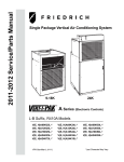
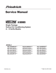
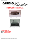
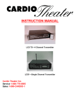
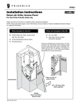
Vert-I-Pak® Single Package Vertical Air Conditioning System A-Series 24,000 BTU/h Installation & Operation Manual 920-159-01 (10-03) 920-159-01 (10-03) Table of Contents Installation Recommendations......................................................................................................................................................... 3 I. General Specifications Model Number Identification Guide ................................................................................................................................... 4 VERT-I-PAK Chassis Specifications ................................................................................................................................... 4 II. 1. 2. 3. 4. 5. 6. 7. 8. Installation Utility Closet Dimensions ................................................................................................................................................... 5 Wall Plenum & Architectural Louver Installation ................................................................................................................ 6 Electrical Information ..................................................................................................................................................... 7-9 Indoor Return Air Grille Installation .................................................................................................................................. 10 Ductwork Preparation and CFM ....................................................................................................................................... 11 Chassis Installation.......................................................................................................................................................... 11 Chassis Final Connections (Electrical, Duct, Drain & Wall Thermostat)............................................................................ 12 Final Installation Checklist............................................................................................................................................... 12 9. 10. 11. 12. 13. Chassis Operation Thermostat Control .......................................................................................................................................................... 12 Low Ambient Protection for Compressor & Fan ................................................................................................................ 12 Heating Defrost (Heat Pump Models only)........................................................................................................................ 12 Fresh Air Door................................................................................................................................................................... 13 Condensate Disposal System .......................................................................................................................................... 13 III. IV. Service, Maintenance & Warranty 14. Servicing / Chassis Quick Changeouts............................................................................................................................. 13 15. Routine Maintenance....................................................................................................................................................... 13 16. Warranty .......................................................................................................................................................................... 14 V. Vert-I-Pak Accessories .................................................................................................................................................... 15 Please read this manual thoroughly prior to equipment installation or operation. It is the installer’s responsibility to properly apply and install the equipment. Installation must be in conformance with the NFPA 70-2002 National Electric Code or current edition and Universal Mechanical Code current edition and applicable local or national codes. Proper installation is not difficult but it is essential. 2 920-159-01 (10-03) Vert-I-Pak Installation Recommendations 6" 60" RECESS OK For proper unit performance and maximum operating life please refer to theSMALL minimum installation clearances below. Figure 1 60" 60" 60" VERT-I-PAK® units must be installed on an outside wall. 60" Confined spaces and/or covered areas should be avoided. Units should be installed no closer than 12" apart when two units are side by side. If three of more units are to operate next to one another allow a minimum of60"60" between units or pairs60" of units. Also, a vertical clearance of 60" should be maintained between units. Units installed on the bottom floor should be mounted 6" 6" at least 6" off of the ground. B 6" 60" SMALL RECESS OK A 60" 60" 60" 60" LARGER RECESS OK. IF A> 5xB 60" 60" 60" 60" 60" 6" 60" 6" 12" B A Figure 2 LARGER RECESS OK. IF A> 5xB 60" Any time obstructions are present use the following guidelines for proper 60" spacing from the VERT-I-PAK louver: 60" BUILDING 60" VPAK • For minor obstructions60" such as lamp poles or small shrubbery a clearance of 24" from the outdoor louver should be maintained. • For major obstructions such as a solid12" fence, wall or other heat rejecting device like a condensing unit, a minimum distance of 72" should be kept. 24" 12" VPAK VPAK 24" POLE SHRUB 72" OUTDOOR CONDENSING UNIT FENCE MAJOR OBSTRUCTION The above suggestions are for reference only and do not represent all possible installations. Please contact the factory for information regarding affects of other installation arrangements. By following these simple recommendations you can be confident that your Friedrich Vert-I-Pak ® will provide years of worry-free operation. 3 920-159-01 (10-03) Section I. General Specifications VERT-I-PAK® MODEL IDENTIFICATION GUIDE MODEL NUMBER V E ENGINEERING CODE SERIES V=Vertical Series E=Cooling with or without electric heat H=Heat Pump OPTIONS RT = Standard Remote Operation SP = Seacoast Protected ELECTRIC HEATER SIZE A-Series 00 = No electric heat 25 = 2.5 KW 34 = 3.4 KW 50 = 5.0 KW 75 = 7.5 KW 10 = 10 KW DESIGN SERIES A = 32" and 47" Cabinet NOMINAL CAPACITY A-Series (Btu/h) 09 = 9,000 12 = 12,000 18 = 18,000 24 = 24,000 VOLTAGE K = 208/230V-1Ph-60Hz Vert-I-Pak® Chassis Specifications MODEL: V(E,H)A24 Voltage (V) 230/208 Refrigerant R-22 Chassis Width 23.125 Chassis Depth 23.125 Chassis Height ** 47.25 Supply Duct Collar *** 10" Drain Connection 3/4" FPT Min. Circuit Amps See Nameplate CFM Indoor See chart, pg. 11 Max. Duct ESP .4 in. water NOTES: ** Height includes 2" duct collar & isolators under unit. *** Factory collar accepts 10" flex duct. 4 A 24 K 50 RT A 920-159-01 (10-03) II. Installation 1) Utility Closet Dimensions Recommended utility closet dimensions and a typical indoor installation are illustrated in Figure 1. Three inches minimum clearance on three sides of the unit must be allowed for return airflow, installation access and service access. See Figures 1 & 2 for clearances and reference dimensions. Typical Utility Closet Figure 3 Chassis Shown in Closet, on Optional Platform Rigid Ductwork Field-supplied Filter (25" x 20") 58" Exterior Wall Flexible Ductwork VPAWP1-8/1-14 Wall Plenum Power Disconnect Plenum 29" VPRG4 Access Panel & Return Air Filter Grille Optional Platform 3" Clearance on all three sides minimum for Figure 4 Chassis is shipped with vibration isolators installed VPDP1 drain pan beneath unit is required on all VEA/VHA24 units. Drain pan must be installed prior to chassis installation Top View • Vert-I-Pak Chassis 2-ton dimensions: 23" wide x 23" deep x 47 1/4" high. control box electrical entrance • VPAWP1-8/1-14 Wall Plenum cut-out dimensions 24 5/8" wide x 30 7/8" high. • VPRG4 Access Panel cutout dimensions: 27" wide by 55 3/4" high. • See Figure 8 (Page 10) for proper chassis installation. NOTE: Drain pan must be installed in closet prior to chassis insertion into plenum. See Figure 7 (page 8) for drain pan installation details. 5 920-159-01 (10-03) 2) Wall Plenum and Architectural Louver Installation A. Install the wall plenum (VPAWP1-8/1-14) components in accordance with the installation instructions provided with each accessory. IMPORTANT REMINDER: FRIEDRICH WALL PLENUM IS NOT DESIGNED TO CARRY STRUCTURAL LOADS. PROPER WALL HEADER CONSTRUCTION IS REQUIRED. THE PLENUM REQUIRES PROPER FLASHING, SHIM AND CAULK FOR A WEATHER RESISTANT INSTALLATION. B. Ensure that the divider is adjusted properly for the depth of the wall in accordance with the accessory installation manual Figure 5 Wall Plenum & Outdoor Louver Installation Proper Header Caulk all 8 flange corners Proper Flashing Proper Caulking Inside Wall Plenum (Part B) Outside Wall Architectural louver VPAL2 mounted on the outside wall plenum (Part A) 6 Proper Caulking Proper Flashing • Rough opening dimension 24 5/8" wide x 30 7/8" high. • Ensure that the bottom of the plenum is 1 1/2" from the floor of the closet. Note: 9,000 / 12,000 / 18,000 installation height may be different. Refer to specific installation manual for clarification. • For proper airflow, maintain a minimum distance of 12" between Vert-I-Pak units. Consult the factory for any installation or application questions. 920-159-01 (10-03) 3) Electrical Information Electrical Data Voltage ( V) LRA - Comp. (A) Cooling Current (A) MIN. Ckt. Amps (A) Max Branch Circuit Fust (Amps) Power Connection Recommended Branch Circuit Wire Sizes* AWG - American Wire Gauge 230/208 68 13.7/12.4 17.2/15.9 25/25 14/14 00 10 K /V EA A VH /V EA A VH 24 24 K 24 VH A /V EA /V EA A VH K 75 50 K 24 24 /V EA A VH VH A /V EA 24 K K 25 34 MODEL 230/208 230/208 230/208 230/208 230/208 68 68 68 68 68 13.7/12.4 13.7/12.4 13.7/12.4 13.7/12.4 13.7/12.4 22.1/20.3 30.7/28.1 44.3/40.3 57.9/52.7 15.6/15.6 25/25 35/30 45/45 60/60 20/20 HARD WIRED 12/12 8/10 6/6 4/6 14/14 * Single circuit from main box. Based on copper wire, single insulated conductor at 60°C. NOTE: Use copper conductors ONLY. Wire sizes are per NEC. Check local codes for overseas applications. Sample Nameplate (see your chassis nameplate) E L P M A S 7 920-159-01 (10-03) IMPORTANT: ALL 208/230V CHASSIS MUST BE HARD WIRED WITH PROPERLY SIZED BREAKER. SEE NAMEPLATE FOR SPECIFIC CHASSIS ELECTRICAL REQUIREMENTS. SEE PAGE 9 - FIGURE 8 FOR UNIT WIRING AND WALL THERMOSTAT WIRING. SEE PAGE 7 FOR WIRE SIZE. USE HACR TYPE BREAKERS TO AVOID NUISANCE TRIPS. ALL FIELD WIRING MUST BE DONE IN ACCORDANCE WITH NEC AND LOCAL CODES. 3) Electrical Information (continued) Figure 6 Electrical Requirements Note: All field wiring must comply with NEC and local codes. It is the responsibility of the installer to insure that the electrical codes are met. CAUTION Electric shock hazard. Wire Size Use ONLY wiring size recommended for single outlet branch circuit. Fuse/Circuit Breaker Use ONLY type and size fuse or HACR circuit breaker indicated on unit's rating plate (See sample on page 6). Proper current protection to the unit is the responsibility of the owner. Grounding Unit MUST be grounded from branch circuit to unit, or through separate ground wire provided on permanently connected units. Be sure that branch circuit or general purpose outlet is grounded. Wire Sizing Use recommended wire size given in tables and install a single branch circuit. All wiring must comply with local and national codes. NOTE: Use copper conductors only. Figure 7 Drain Connection and Location Turn OFF electric power before service or installation. All electrical connections and wiring MUST be installed by a qualified electrician and conform to the National Electrical Code and all local codes which have jurisdiction. Failure to do so can result in property damage, personal injury and/or death. CAUTION THE ACCESSORY DRAIN PAN (VPDP1) MUST BE INSTALLED BEFORE INSTALLING THE UNIT. 1. The accessory drain pan has two (2) provisions (left & right) for connecting an external condensate drain. 2. A field supplied condensate drain system must be connected to one of the two 3/4" FPT connections. 3. The remaining connection must be plugged using the 3/4" pipe plug (provided) and field suppled teflon tape or pipe joint compound. 4. Failure to follow these procedures may result in serious property damage. 8 920-159-01 (10-03) 3) Electrical Data (continued) Figure 8 Electrical & Thermostat Wiring Diagrams FOR 208 VOLT MODELS ONLY MOVE THE WHITE WIRE AS SHOWN BELOW WHITE BLACK RT2 THERMOSTAT (FRONT) COM. 208V 240V TRANSFORMER THERMOSTAT CONNECTIONS (EAR) 24V UP G R R W B Y C RED BLACK WHITE RED HEATER 2.5 KW & 3.4 KW 5 KW YELLOW BROWN HEATER 7.5 KW & 10 KW COIL, SOLENOID QUICK DISCONNECT RED RED L1 L2 RED BLACK BLACK RED R G B M WHITE 24V 2 4 1 3 BLACK W Y CAPACITOR LOW AMBIENT CONTROL RED RED RED RED RED WHITE PRESSURE SWITCH COM. 208V 240V TRANSFORMER HER C FAN TERM BOARD WHITE HEAT RELAY HEAT RELAY REV VALVE RELAY FAN RELAY COMPR RELAY YELLOW c BLACK BLUE RED "F" "F"C"F" R S COMPRESSOR RED BLACK BLACK BLUE RED COMP WIRE HARNESS YELLOW WHITE WHITE 2 4 2 4 2 4 1 3 1 3 1 3 BLACK (2.5KW/3.4KW 5 KW) 2 4 1 3 (2.5KW/3.4KW 5 KW) BLACK BLACK BLACK BLACK HEAT RELAY (7.5KW/10KW) 2 4 1 3 HEAT RELAY (7.5KW/10KW) 2 4 1 3 BLACK BLACK WIRE NUT (RED) GREEN BLACK SEE NOTE #6 BLACK RED BLUE GREEN BROWN RED C YELLOW T-STAT DEFROST H BLACK INSULATOR L WHITE 2-REQ'D GREEN WHITE CAPACITOR c NOTE: WHITE CONDENSER MOTOR BROWN FAN GREEN TO MOTOR MOUNT BLUE WHITE RM HE BROWN TO MOTOR MOUNT WIRE NUT (RED) BLOWER MOTOR SEE NOTE #4 BLACK THE DIAGRAM ABOVE ILLUSTRATES THE TYPICAL THERMOSTAT WIRING AND 208 VOLT TRANSFORMER WIRING. SEE THE UNIT CONTROL PANEL FOR THE ACTUAL UNIT WIRING DIAGRAM AND SCHEMATIC. 9 920-159-01 (10-03) 4) Indoor Return Air Grille Installation There are three Indoor Return Air Grille options as shown in Figure 9. Choose the option that best suits your needs. Use the installation instructions provided with accessories for installation details. Figure 9 Return Air Grille Options Option 1 VPRG4 Return Air Grille with Access Panel A field-supplied (25" x 20") filter is mounted inside the hinged access door. Option 2 VPRG2 Return Air Grille All Vert-I-Pak chassis are shipped with a 20" x 14" filter installed. If an accessory filter holder is to be used, you MUST remove the factory shipped filter from the chassis. Do NOT use two filters Unit requires a field-supplied access door or panel and a 16" x 20" filter. Notes: A. These are the Friedrich recommended return air grille / filter / access panel arrangements. Consult the factory on other arrangements. Improper return air arrangements will cause performance problems. B. Return air arrangements are shown from the front, but can also be installed from the right or left side of the unit. 10 920-159-01 (10-03) 5) Indoor Airflow Data 6) Chassis Installation The Vert-I-Pak A series units must be installed with a free return air configuration. The table below lists the indoor airflow at corresponding static pressures. All units are shipped from the factory and are rated at low speed. NOTE: Prior to installing the chassis, ensure that the drain pan and line are free from debris. To change to high speed replace the low speed lead (blue) with the high speed lead (black) on the blower relay. .1” ESP .2” ESP .3” ESP .4” ESP VEA/VHA24K Low High 750 815 725 780 700 745 675 700 All values listed are inches W.C. with a wet indoor coil with filter installed. A. Ensure that the wall plenum is installed in accordance with the VPAWP1-8/1-14 Installation Manual. B. Ensure that the VPDP1 drain pan is installed correctly (see page 8). Using the 3/4" plugs supplied with the pan, plug the unused condensate drain hole. Connect a drain to the condensate exit location. Be sure to use teflon tape or approved pipe sealant on all drain connections and plugs (see page 8). C. Place the chassis into the closet with the outdoor side facing the wall plenum opening. D. Slide the chassis into the wall plenum until the plenum divider seal is established and the factory-installed chassis to plenum gasket has sealed to the top flange of the plenum. (See Figure 10) Figure 10 Slide-in View / Chassis Installation Chassis to plenum gasket The Vert-I-Pak chassis must be inserted into the wall plenum so that the plenum divider gasket makes contact with the condenser baffle in the unit. The chassis will fit approximately 2 3/ 8" into the wall plenum. NOTE: Prior to installing the chassis, ensure that the drain pan and line are free from debris. 2 3/8 11 920-159-01 (10-03) 7) Chassis Final Connections With the chassis in place, you are now ready to begin chassis connections: A. Move the thermostat switches to "OFF" and "AUTO." This will keep the thermostat from cycling the chassis until final connections are complete. B. Connect the ductwork onto the 10" collar. Plastic wireties (field supplied) are suggested to secure the ductwork in place. Use 2 wire ties, one for each inner and outer flex duct sleeve. RT2 Digital Thermostat D. For 208 Volt power only: you must move the transformer wire as shown in Figure 8, Page 9. III. Chassis Operation E. Review the Final Installation Checklist on Page 12 before replacing the power quick disconnect, reconnecting power to the chassis, plugging in the remote thermostat harness, or operating the chassis. 9) Remote Thermostat Control Electrical shock and moving parts hazard can cause injury or death. If you have not done so, pull out the disconnect head found on the front of chassis before continuing installation! Disconnect external power at the breaker. 8) Final Installation Checklist 12 o Correct line voltage? o Chassis deck level? o Plenum divider baffle installed? o Wall plenum caulked? Level? Flashing? o HACR type breaker/fuse? o Single circuit only? o Ductwork connected? o Chassis weather seal in place? o Wall thermostat wired correctly? o Chassis inserted into plenum? The chassis requires a simple single stage heat-cool wall thermostat. Each chassis comes with a terminal strip located in the electrical control box. All internal chassis wiring (low & high voltage) is factory ready for 230 Volt operation. For 208 Volt operation a single wire MUST BE CHANGED ON THE TRANSFORMER. Refer to Figure 8 on page 9. 10) Low Ambient Protection Each chassis is equipped with Low Ambient Protection in the form of a suction line thermostat. This thermostat will prevent compressor operation at low suction line temperatures. Each chassis is also equipped with a factory installed bellows that will drain water from the base pan to prevent the fan slinger from freezing during winter weather. 11) Heating Defrost (Heat Pump Models Only) All Heat Pumps have a passive heating defrost system. Defrost occurs as needed and automatically switches to electric heat during defrost. When the outdoor ambient temperature drops below a 45°F factory setting, the chassis automatically switches to electric heat. As outdoor ambient temperatures rise above 45°F, the chassis returns to the heat pump mode. The changeover temperature is user adjustable from approximately 32°F - 55°F. The defrost thermostat may also be used to lock out the compressor in an emergency heat situation. 920-159-01 (10-03) 12) Fresh Air Door 15) Routine Maintenance The Fresh Air Door is an "intake" system. The fresh air door is opened via a slide on the front of the chassis located just above the indoor coil. Move the slide left to open and right to close the fresh air door. The system is capable of up to 60 CFM of fresh air @ ~.3" H20 internal static pressure. Performing Routine Maintenance 13) Condensate Disposal System The VPDP1 drain pan features two 3⁄4 female PVC fittings to attach a drain connection to on the left or right side of the drain pan. Condensate piping can be routed to the left, right or beneath the unit platform. See page 8 or the drain pan installation manual for more information. Part 1: The system’s first stage increases energy efficiency utilizing a factory installed fan that slings the cold condensate onto the hot outdoor coil. Part 2: When high outdoor humidity prevents the slinger from disposing of all the condensate, the excess condensate overflows into the condensate drain pan and out of the 3⁄4" internal drain connections. Part 3: If Parts 1 & 2 fail for any reason, excess condensate overflows from a spillway directly into the wall plenum to the outside of the building. IF THIS OCCURS, THIS IS YOUR WARNING THAT THE CHASSIS OR DRAIN NEEDS SERVICING. IV. Service & Warranty 14) Servicing / Chassis Quick Changeouts The chassis is designed for quick disconnect and change out. For minor electrical service, the control box cover lifts straight up after the screws & disconnect head are removed. For major electrical, refrigeration and fan service the chassis may be removed from utility closet. With the proper maintenance and care, your system will operate economically and dependably. Maintenance can be accomplished easily by referring to the following directions. However, before performing any maintenance, consider these important safety precautions: WARNING: Electrical Shock Hazard. Before attempting any service work or routine maintenance, turn off all electrical connections to the unit. Failure to do so may result in property damage, personal injury and/or death. CAUTION: Although great care has been taken to minimize sharp edges in the construction of your unit, be extremely careful when handling parts or reaching into the unit. Replace Air Filter A dirty air filter reduces the efficiency of your Vert-I-Pak and allows lint and dirt to accumulate on the indoor-air coil. Lint and dirt on the indoor-air coil can damage your unit and void the warranty. The air filter should be replaced as it becomes dirty. To replace the filter (chassis mounted return air filter): 1. Slide the filter clear of the filter rails. 2. Remove the filter. 3. Install new disposable filter. CAUTION: Do not operate your system without a filter in place, nor block the front of the unit return air opening. Inspect and Clean Indoor-air Coil Eventually, minor amounts of lint and dirt may pass through the filter and collect on the indoor-air coil. These minor accumulations can be carefully vacuumed away with a brush attachment on a vacuum cleaner. Care must be taken to avoid bending the aluminum fins on the coil. Bent fins should be straightened using a special fin tool available from most HVAC service technicians. Inspect Outdoor-air Intake and Exhaust C. Disconnect the thermostat wiring harness. The unit’s outdoor-air intake and outdoor-air exhaust paths must remain clear. Check the OA exhaust frequently. Keep it free of all debris, snow, or ice. The OA intake should also be kept free of obstructions. Blocking the OA exhaust or OA intake opening will reduce the efficiency of your unit, could damage it, and may void your warranty. D. Disconnect the electrical connection. Inspect and Clean Condensate Drain To Remove the Chassis from the Closet: A. Switch the wall Thermostat off. B. Pull the Power Disconnect located in the front of the chassis. E. Disconnect the ductwork. F. Slide the chassis out of the wall plenum. G. Lift the chassis out of the utility closet. Electrical shock and moving parts hazard can cause injury or death. Pull out the disconnect head found on the front of the chassis before servicing. The condensate drain must be routed to a suitable drainage area. Check the unit condensate drain periodically. Keep it free of anything that may block or impede the flow of condensate water. If there is any accumulation of foreign matter in the drain pipe, it should be removed and cleaned. The entire drain line must be protected from freezing. 16) Warranty All service work must be done by a qualified servicer. See Warranty on the next page, and consult your dealer or contractor for details 13 920-159-01 (10-03) FRIEDRICH AIR CONDITIONING CO. Post Office Box 1540 · San Antonio, Texas 78295-1540 (210) 357-4400 · FAX (210) 357-4480 VERT- I-PAK® A SERIES SINGLE PACKAGE VERTICAL AIR CONDITIONERS LIMITED WARRANTY SAVE THIS CERTIFICATE. It gives you specific rights, you may also have other rights which may vary from state to state and province to province. In the event that your unit needs servicing, contact your nearest authorized service center. If you do not know the nearest service center, ask the company that installed your unit or contact us - see address and telephone number below. To obtain service and/or warranty parts replacement, you must notify an authorized FRIEDRICH Air Conditioning Co. service center, distributor, dealer, or contractor of any defect within the applicable warranty period. When requesting service: please have the model and serial number from your unit readily available. Unless specified otherwise herein, the following applies: FRIEDRICH VERT-I-PAK A SERIES VERTICAL AIR CONDITIONERS AND HEAT PUMPS LIMITED WARRANTY - FIRST YEAR (Twelve (12) months from the date of installation). Any part found to be defective in the material or workmanship will be repaired or replaced free of charge by our authorized service center during the normal working hours; and LIMITED WARRANTY - SECOND THROUGH FIFTH YEAR (Sixty (60) months from the date of installation). ON THE SEALED REFRIGERATION SYSTEM. Any part of the sealed refrigeration system that is defective in material or workmanship will be repaired or replaced free of charge (excluding freight charges) by our authorized service center during normal working hours. The sealed refrigeration system consists of the compressor, metering device, evaporator, condenser, reversing valve, check valve, and the interconnecting tubing. These warranties apply only while the unit remains at the original site and only to units installed inside the continental United States, Alaska, Hawaii, Puerto Rico and Canada. The warranty applies only if the unit is installed and operated in accordance with the printed instructions and in compliance with applicable local installation and building codes and good trade practices. For international warranty information, contact the Friedrich Air Conditioning Company - International Division. Any defective part to be replaced must be made available to FRIEDRICH in exchange for the replacement part. Reasonable proof must be presented to establish the date of install, otherwise the beginning date of this certificate will be considered to be our shipment date plus sixty days. Replacement parts can be new or remanufactured. Replacement parts and labor are only warranted for any unused portion of the unit’s warranty. We will not be responsible for and the user will pay for: 1. Service calls to: A) Instruct on unit operation. B) Replace house fuses or correct house wiring. C) Clean or replace air filters. D) Remove the unit from its installed location when not accessible for service required. E) Correct improper installations. 2. Parts or labor provided by anyone other than an authorized service center. 3. Damage caused by: A) Accident, abuse, negligence, misuse, riot, fire, flood, or acts of God. B) Operating the unit where there is a corrosive atmosphere containing chlorine, fluorine, or any damaging chemicals (other than in a normal residential environment). C) Unauthorized alteration or repair of the unit, which in turn affects its stability or performance. D) Failing to provide proper maintenance and service. E) Using other than a “Seacoast Protected” unit in a coastal environment. F) Using an incorrect power source. G) Faulty installation or application of the unit. We shall not be liable for any incidental, consequential, or special damages or expenses in connection with any use or failure of this unit. We have not made and do not make any representation or warranty of fitness for a particular use or purpose and there is no implied condition of fitness for a particular use or purpose. We make no expressed warranties except as stated in this certificate. No one is authorized to change this certificate or to create for us any other obligation or liability in connection with this unit. Any implied warranties shall last for one year after the original purchase date. Some states and provinces do not allow limitations on how long an implied warranty or condition lasts, so the above limitations or exclusions may not apply to you. The provisions of this warranty are in addition to and not a modification of or subtraction from the statutory warranties and other rights and remedies provided by law. In case of any questions regarding the provisions of this warranty, the English version will govern. Rev 9-03 14 920-159-01 (10-03) IV. Vert-I-Pak Accessories MODEL DESCRIPTION VPAWP1-8 WALL PLENUM Two-part sleeve that telescopes in and out from 5 1/2" to 8" in depth. The wall plenum sits inside the exterior wall penetration. DIMENSIONS: 30 3/8" high x 24 1/8" wide. CUTOUT DIMENSIONS: 30 7/8" high x 24 5/8" wide. VPAWP1-14 Same as VPAWP1-8, but telescopes 8" to 14" as required. VPAL2 ARCHITECTURAL LOUVER Extruded aluminum louver that attaches to the outdoor section of the wall plenum. DIMENSIONS: 31 1/16" high x 25 9/16" wide. VPSC2 Same as VPAL2 but can be ordered in a special color to match the exterior wall. RT2 PHOTO DIGITAL THERMOSTAT Digital electronic thermostat with "one touch" adjustment. Mounts to wall for control of unit. VPRG4 ACCESS PANEL / RETURN AIR GRILLE Serves as an access panel to chassis and interior return air grille. A Þeld-supplied (25" x 20") Þlter is mounted inside the hinged access door. DIMENSIONS: 58" high x 29" wide. CUTOUT DIMENSIONS: 553/4" high x 27" wide. VPRG2 RETURN AIR GRILLE Interior return air grille that hinges to allow a Þeld supplied (16" x 20") Þlter to slip inside. Must be used when an access door / panel already exists in closet. DIMENSIONS: 18 7/16" high x 22 3/8" wide. VPDP1 DRAIN PAN for VEA/VHA24 models. Drain pan may be installed prior to chassis for easy installation/removal. 15 Use Factory Certified Parts. FRIEDRICH AIR CONDITIONING CO. Post Office Box 1540 · San Antonio, Texas 78295-1540 4200 N. Pan Am Expressway · San Antonio, Texas 78218-5212 (210) 357-4400 · Fax (210) 357-4480 www.friedrich.com Printed in the U.S.A. 920-159-01 (10-03)