1
AFX Series
Precision Air Conditioning
OPERATION AND MAINTENANCE
MANUAL
February 10, 2003
This manual provides information for installation, operation and preventive
maintenance. The user should observe the guidelines and procedures presented herein
to promote satisfactory performance. Due to an ongoing program dedicated to product
improvement, specifications are subject to revision without notice. APC assumes no
responsibility, and disclaims all liability for damages resulting from use of this
information or for any errors or omissions.
American Power Conversion
132 Fairgrounds Road
West Kingston, RI 02892
Telephone: 800-800-4APC
Website: www.apc.com
Introduction
Congratulations on the selection of an APC
environmental control system. The unit
incorporates the latest system design
innovations to provide you with optimum
efficiency, reliability and control accuracy.
The AFX Series System will provide years
of trouble free service, provided it is
installed and maintained by technically
qualified personnel in accordance with the
guidelines set forth in this manual.
Table of Contents
Introduction ..................................................................................................................................
The AFX Series ............................................................................................................................
Standard Features .......................................................................................................................
Optional Equipment .....................................................................................................................
Installation ....................................................................................................................................
Piping Connections ......................................................................................................................
Pre Start-Up .................................................................................................................................
Start-Up........................................................................................................................................
Charging of the System ...............................................................................................................
System Function ..........................................................................................................................
Control/Safety Adjustments .........................................................................................................
Humidifier Operation....................................................................................................................
Troubleshooting ...........................................................................................................................
Preventive Maintenance ..............................................................................................................
Warranty Procedure.....................................................................................................................
Sample Warranty .........................................................................................................................
1
2
3
4
6
10
11
11
12
12
13
15
16
20
21
22
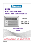
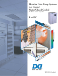
The AFX Series
The APC AFX series precision air-conditioning
system provides compact, quiet, efficient, and
reliable system solutions in the expanding
precision air-conditioning market. The AFX
series is offered in a wide variety of capacities,
configurations, and air patterns within an
extremely compact cabinet size.
Precision environmental control requirements
now reach far beyond the confines of the
traditional data or computer room to encompass
a larger suite of applications, referred to as
technology rooms.
A worldwide network of APC representatives is
fully qualified to provide engineering, sales,
installation and service for our products.
Capacity
Available are 6 through 28 tons (20 kW–96 kW).
Air Pattern
Downflow units discharge air into the raised floor
plenum eliminating the need for air distributing
ductwork. Upflow units discharge air into either a
plenum or ductwork.
Control
The microprocessor controller provides
advanced integrated system operation and
management ensuring simple, reliable and
precise temperature and humidity control.
Configuration
Air-cooled. Unit used with an air-cooled
condenser. Refrigerant lines must be run
between the indoor unit and the condenser. Aircooled units require low maintenance and have
low operating costs.
.
Water-cooled. Unit used with a cooling tower or
other source of water. Field refrigeration piping
is eliminated by a factory sealed and tested
system. Water piping to and from the unit is
required.
Glycol-cooled. Unit used with a drycooler. The
need for field refrigeration piping is eliminated by
a factory sealed and tested system. The glycol
piping is sealed, eliminating costly water
treatment often encountered with open cooling
towers.
Remote-condensing. Unit used with a remote
air-cooled condensing unit, which includes the
compressor(s). This allows key maintenance
procedures to be located outside the critical
environment helping eliminate access by
maintenance personnel in high security areas.
Available in air, water, and glycol models.
Serviceability
The AFX Series has full service front access for
routine servicing of components. Front access
also narrows the footprint of the unit making it
possible for units to be placed side by side.
Humidity Control
Humidity is managed through a self-contained
steam canister humidifier for maximum
efficiency and ease of maintenance.
Dehumidification control is assured with a split
evaporator coil, which decreases the humidity
level without over-cooling the space, therefore
reducing the need for electric reheat.
Compliance
The AFX Series has received agency approvals
by ETL and MEA #223-99-E. Electrical systems
comply with NEC and UL 1995 standards.
Standard Features
Overall cabinet
The frame is constructed of heavy gauge steel
for maximum strength. The unit has been
designed for full service access from the front.
The flush mounted panels are removable using
quarter-turn fasteners.
Blower Assembly
The AFX series includes multiple, centrifugal
blower assemblies that have been engineered
for quite, reliable operation. Lower blower
speeds reduce noise and extend belt and
bearing life to 200,000L10. Permanently
lubricated bearings, a single-belt variable pitch
drive, and an adjustable motor base insure
dependable operation. Air return patterns evenly
distribute air across the cooling coil.
Electrical panel
The electrical panel contains the contactors,
starters, overload protection devices, and input
power disconnects. Each wire (except jumpers)
is numbered every 3" (80 mm), or color-coded to
facilitate circuit tracing when installing and
servicing the unit. Each AC power circuit is
individually circuit breaker protected on all three
phases. All compressor and motor devices are
thermally and short circuit protected. Electrical
panel is easily accessible from the front of the
unit. All electrical components are UL-listed andrecognized and all wiring conforms to NFPA 70
(NEC) and UL 1995 requirements.
Humidifier
The humidifier utilizes a pure steam generator
specifically designed for hi-tech area
environmental control. The pure steam
eliminates contaminating mineral deposits,
potentially deadly bacteria, white dust and
excessive humidity. The humidifier requires little
or no scheduled maintenance. Automatic
flushing combined with an indicator that signals
when the canister is to be changed, ensure
maintenance free operation.
Electric reheat
A three-phase electrical resistance heater sized
to offset the sensible cooling capacity in the
dehumidification mode. Reheat elements are
3
low watt density sheathed components. The
reheat is three phase to provide even phase
loading. Reheat elements are electrically and
thermally protected.
Refrigeration system
The refrigeration system consists of a single
hermetic compressor, externally equalized
expansion valve, filter-dryer, high pressure
switch, refrigerant sight glass, and moisture
indicator.
Cooling coil
Utilizes dual distributors on one circuit of the
refrigeration system. During dehumidification,
the smaller distributor is turned off, effectively
reducing the active circuits of the evaporator coil
resulting in a decreased SHR of the coil and
greater percentage of moisture removal.
Air filter
The AFX series uses 30% efficient 4" deep
filters, with full depth filter pleats. Filters are
easily replaced from the top on downflow units
and from the front on upflow units.
Airflow sensor
Upon detection of a loss of air flow the
microprocessor will deactivate: cooling, heating,
humidification, and dehumidification. After the air
flow has been restored for a predetermined
period of time, the microprocessor will reactivate
functions as needed.
Clogged filter alarm
An adjustable air pressure differential switch
senses the pressure drop across the filters.
Upon sensing an excessive pressure drop, the
switch activates the alarm circuit of the
microprocessor and displays a clogged filter
message simultaneously with an audible signal.
Emergency drain pan
Systems are provided with two drain pans. A
threaded flange is factory supplied for secondary
drain connections.
Optional Equipment
Smoke detector(s)
A factory installed smoke detector is designed to
sense smoke concentration in the return air
stream. Upon detecting smoke concentration an
audible and visual alarm will be activated and
the unit will immediately shut down.
Firestat
A Firestat is available for installation in the air
stream. If the return air temperature reaches
125° F (52° C), the air conditioner will be turned
off and both an audible and visual alarm will be
activated.
Water detector(s)
The solid-state water detector activates an
audible and visual alarm on the microprocessor
when moisture is detected. The water detector is
provided with 15’ of wire.
Remote relay shutdown
A factory installed relay can be ordered with a
24V, 120V, or 240V coil to remotely disable the
NetworkAIR system.
Essential/non-essential lockout
When facilities have limited backup power
capacity, this lockout prevents the operation of
electrical loads that are not essential for
continued site operation.
Floorstand
The heavy gauge floorstand raises the unit
above the subfloor to match the height of the
raised floor. Heights are available from 6” to 36”
in 3” increments. Adjustment is provided by
threaded pedestals.
Air deflector
An air deflector ships loose and attaches to the
floorstand for changing air direction from vertical
to horizontal.
Plenum
The discharge plenum mounts on top of the
upflow unit to direct and distribute conditioned
air. Manually adjustable, double deflecting grilles
are provided on 3 or 4 sides.
Duct flange
A 1” (25mm) duct flange is installed on a unit to
provide convenient connection to external
ductwork. The duct flange can be installed at the
air outlet on upflow units, at the air inlet on
upflow rear return units, or at the air inlet on
downflow units.
Dry contact closure alarms
Each unit can be equipped with any or all of the
listed dry contact closures. Upon activation of
the associated
alarm, a discreet Normally-Open or NormallyClosed contact is available for remote
monitoring of that discreet alarm.
• High Temperature Alarm
• Low Temperature Alarm
• High Humidity Alarm
• Low Humidity Alarm
• Fan Status Alarm
• Change Filter Alarm
• Fire Alarm (with addition of optional firestat)
• Smoke Detector Alarm (with addition of
optional smoke detector)
• Humidifier Change Canister Alarm
• Water Underfloor Alarm (with addition of water
detector)
Redundant group control
Allows up to six NetworkAIR units the ability to
communicate with each other to automatically
switch upon alarm condition, or timed rotation.
Can also allow standby units the ability to assist
the running system.
Remote display panel
The microprocessor controller allows facility or
building-maintenance personnel to evaluate and
control the unit from up to 50 ft. away from the
unit, without having to enter the secured space.
Remote sensor(s)
Environmental sensors can be strategically
placed, up to 50 ft. from the unit to better meet
the sites cooling needs. The sensor must be
positioned to permit air movement across the
sensors.
Optional Equipment (continued)
Environmental monitoring unit
A stand-alone unit performs continuous
temperature and humidity sensing through two
available probes (one included) and contact
monitoring. The unit is controlled by available
web, control console, or SNMP interface with
network connection. In the event of an
environmental anomaly, notification is sent to
the customer via e-mail or SNMP. The unit is
18.25" × 9" × 2.75" (464 mm × 229 mm × 70
mm) and sits in or on top of a rack. The probes
extend up to 12' (3.66 m) from the unit.
Condensate pump
The factory installed and wired condensate
pump will pump 36 gal/h (0.06 L/s) at 15ft. (4.6
m) head.
Hot water or steam reheat
An on/off solenoid valve for steam reheat, or a
modulating valve for hot water reheat maintains
the dry bulb temperature when the system is in
dehumidification and heat mode. Completely
factory pre-piped, the system includes a copper
tube, aluminum-fin reheat coil, solenoid valve,
float, and thermostatic and steam trap for steam
reheat only.
Hot gas bypass
An auxiliary side-port hot gas bypass circuit. The
activation of the hot gas bypass circuit will
maintain the evaporator coil temperature during
low load conditions will offer longer compressor
run times and minimize compressor cycling and
temperature fluctuations.
Hot gas reheat
The copper tube, aluminum fin hot gas reheat
coil maintains the leaving dry bulb temperature
when the system is in the dehumidification
mode. The coil is controlled by the
microprocessor through a factory-piped and
wired three-way heat reclaim regulator and
check valve (water/glycol only).
High efficiency filter(s)
Pleated final filters with an efficiency of 40% and
60% (ASHRAE 52.2), 4" (102 mm) deep, allow
the removal of a greater percentage of airborne
particulate contaminates.
Prefilter(s)
Intended to capture large airborne particulate
contaminates, thereby extending the life of the
high-efficiency filter. Prefilters are 1" (25mm)
deep and easily disposable.
5
High pressure water regulating valve(s)
Water and glycol systems may utilize an optional
regulating valve, which operates with a
maximum pressure of 350 psi (2400 kPa), to
automatically control condensing temperature.
Installation
Computer Room Preparation
During the design of the computer room,
consideration should be given to the following
factors: ease of entry, floor loading factors and
accessibility of piping and wiring.
The room must be sealed with a vapor barrier to
minimize moisture infiltration. Polyethylene film
(plastic sheeting) is a good vapor barrier for
ceiling and wall applications. Rubber or plasticbased paints should be applied to concrete
floors and walls.
The room should be thoroughly insulated to
minimize thermal loads and make-up air should
be kept to a minimum to reduce additional
temperature, filtration and moisture loads.
Receiving the Unit
Your AFX unit has been completely tested and
inspected prior to shipment from APC. To
ensure that you have received the unit in
excellent condition, perform a careful inspection
of the crating and the unit immediately upon
receipt. Verify that all parts ordered were
received as specified and that the unit is the
correct size and voltage necessary to fulfill your
environmental control needs. Report any
apparent or concealed damage discovered to
the freight carrier for insurance purposes. If
necessary, contact APC’s technical service
department for aid in repairing or replacing
damaged parts. While APC is not responsible for
exterior or interior damages incurred in transit,
we want to make sure that you have no undue
delays in your system start-up.
A computer room using a raised floor plenum for
air distribution should have at least 12 inches of
clear space between the false floor and sub-floor
for air conditioners below 15 ton capacities. Pay
special attention to the location of pipe chases,
electrical conduits and other underfloor
obstructions. These objects can block air
circulation and increase air pressure drops thus
reducing system efficiency and causing possible
hot spots in your data processing room.
Minimum clear space for larger rooms should be
18 inches when air conditioners of 15 tons
capacity and larger are utilized.
Rigging
The AFX air conditioner is manufactured with a
formed steel frame for maximum strength and
unit integrity. However, as with all
electrical/mechanical equipment, care must be
taken in proper rigging of your AFX unit. If you
uncrate the unit before moving it into place, we
suggest that the panels be removed to prevent
damage during handling.
Unit Location
Unit location is important for efficient and even
environmental control in your data center. The
air conditioners should be located as close to
the largest heat load as possible. Units should
be mounted along the longest walls (in rooms
having a high aspect ratio) to ensure even air
distribution. Erratic control or mechanical failure
can and will result if the unit does not obtain
proper air volume and distribution due to
improper installation
Every unit has sockets in the bottom corners
sized to accept casters with 7/8” stems (casters
are available from the factory, if desired).
Casters allow the unit to move through halls and
rooms where forklifts are not practical.
Service Access
At least 30 inches of clear space must be left in
front of the AFX Series unit and at least 24
inches on each side for access through the
panels and to facilitate service.
When using a forklift to move the AFX unit, use
the shipping skid to protect the bottom of the
unit. When using chains, cable or rope to lift the
unit, use spreader bars to prevent damage to
the finished panels.
Unit Installation
DOWNFLOW DISCHARGE
If your data center has been designed to
incorporate a raised floor, the space between
the raised floor and subfloor may be used as an
air distribution plenum or a chase where ducting
to discharge grilles may be installed. Downflow
discharge units may be installed directly on the
raised floor after ensuring the floor loading
factory is satisfactory to support the unit.
6
Installation (continued)
UPFLOW DISCHARGE
In data processing facilities designed for upflow
discharge systems, air distribution is either
through a supply duct or through a discharge
plenum into the conditioned space. The same
unit location considerations for a downflow
discharge system also apply to upflow discharge
systems.
FLOORSTAND
When using a stand on raised floors, remove or
cut the flooring to fit the floor stand dimensions.
If the unit is close to a wall at the back, ensure
this gap is sealed with flooring or another type of
partition. Place the floorstand in the correct
location with the pedestals going into the
pedestal socket on the floorstand and place the
cork-rubber vibration pad under the pedestal.
Once you have positioned the floorstand and
pedestal arrangement, we suggest you put a
small amount of adhesive between the pedestal
and the pad, and between the pad and subfloor
to keep the unit from moving. Level the floor
stand assembly to within ¼” using the
adjustment nuts on the threaded pedestal legs.
Seal all the way around the upper perimeter of
the floor stand with a flexible airtight gasket or
sealer to prevent air leakage. Floorstands are
available from APC with ?1.5” adjustment range
to meet 95% of the installation requirements
without any modification to the floorstand
assembly. If necessary, the threaded rod may
be cut to meet specific installation requirements.
We suggest that the leveling nuts be put on the
rod before cutting in case the thread is burred or
damaged when cut.
PEDESTAL MOUNTS
The unit has been supplied with pedestal
sockets so that a floorstand is not necessary for
system installation. When using pedestal
mounts on a raised floor, cut the floor to fit the
unit’s frame perimeter. Level the unit to within ¼”
using the adjustable nuts on the pedestal legs.
Seal the gap between the unit and the raised
7
floor with a flexible air tight gasket. Use a small
amount of adhesive between the pedestal, pad
and subfloor to preclude pedestal movement.
Supply & Return Air Relief
FLOOR DISCHARGE
An adequate number of perforated panels must
be installed in the floor to allow for proper air
distribution in the conditioned space. Be sure to
allow sufficient relief near heavier heat loads.
FREE DISCHARGE
Free discharge systems provide conditioned air
to the data processing facility through a
discharge plenum with two-way adjustable
grilles located on top of the air conditioners. The
discharge plenum is shipped separately from the
AFX upflow discharge unit to facilitate handling.
After installing the unit, place the discharge
plenum on top of the unit and bolt it into place
using the hardware supplied.
DUCTED DISCHARGE
A discharge plenum is provided without air
grilles for AFX units that are connected to a duct
supply distribution system. The ducted
discharge plenum is also shipped separately
from the unit. Installation for this unit is the same
as for a free discharge unit. Ducted discharge
units should be located near the heaviest load.
GENERAL – AIR DISTRIBUTION
The AFX direct expansion unit provides full rated
air delivery at 0.5 external static pressure.
Therefore, the air distribution system (plus the
return air duct and grilles if the return air is also
ducted) should not exceed 0.5 inches wg. unless
the unit has been specially ordered for an
increased air pressure drop.
Installation (continued)
Power Connection
The AFX unit uses three phase power for
operation. Bring the service cable through the
3/4" bulk head hole near the electric box and
connect it to the power distribution block provided on the left side of the electric box. All
wiring must be done in accordance with local
and national electric codes.
Utility Connections
All connections are made through the side of the
mechanical section of the air conditioner for
ease of service connection.
Grounding
A ground lug is located next to the high voltage
connection. It must be used.
Condensate Drain Connection
Condensation from the evaporator pan and the
discharge from the optional humidifier system
drains through a drain in the side of the unit.
The installing agency should provide a P-trap
and the piping for this zero drain with slope to
allow for free drainage.
Optional Humidifier Connection
The humidifier inlet connection is in the bottom
mechanical section. A 1/4" compression
connection is supplied with the unit.
Water Supply to Humidifier Connection
1. The humidifier fill valve(s) orifice is sized for
supply water pressure from 30 to 85 psig.
2. For water pressure between 15 and 30 psig,
notify the factory and a larger fill valve will
be supplied.
3. For installation with less than 15 psig, notify
the factory and a fill valve with a specially
4. For applications above 85 psig, install a
pressure-reducing valve in the water feed
line to the unit.
5. With extremely dirty or muddy water
sources, proper filtration is required on the
unit's entering water line.
6.
DO NOT use softened water with the
humidifier because it is too conductive.
7. DO NOT use completely demineralized
water with the humidifier. Minerals allow the
electrode principle to work.
8. DO NOT use a hot water source. It will
cause deposits to eventually block the fill
valve orifice.
9. Water supplies with high conductivity (above
700 microhms) must be preconditioned for
proper humidifier operation and longevity.
10. Consult the Humidifier Operation &
Maintenance Manual included with this AFX
unit for more in-depth information and
troubleshooting procedures.
Outdoor Heat Exchanger Installation
The Outdoor Heat Exchanger (OHE) should be
located in a high security area. Consideration
must be given to ensure a minimum of 24”
clearance from any adjacent wall. The area
should be clear of paper and debris that might
be drawn into the coil.
Be aware of air movements that may cause
short-circuiting of the entering and leaving
condenser air.
The OHE must be mounted on a level surface
with sufficient support to carry the unit’s weight
when fully charged. The heat exchanger has
mounting holes to permit the unit to be bolted
down to prevent shifting. Consult the OHE
Installation Manual for proper set-up.
Before operating, all OHEs should be checked
as follows:
1. Check set screws on all fan hubs.
2. Ensure that fans turn freely and that the
blades are not distorted.
3. Ensure that fans rotate in the proper
direction.
The installing agency should provide a main
power disconnect to isolate the OHE during
routine service or an emergency. Consult the
OHE electrical data table for specific electrical
information
8
Installation (continued)
Drycooler and Pump Package Connection
Provide sufficient valves and unions to isolate
the dry cooler and pump package during routine
service or in the event of an emergency.
Pipe should be welded wherever possible to
minimize leak possibility.
Pipe and wire the dry cooler/precool system in
accordance with local and national codes. A
wiring diagram is attached to the inside of each
control panel cover. The control enclosures are
weather protected and should be mounted close
to the header end of the drycooler. All
thermostats should be checked for the proper
set point per the wiring diagram. Any remote
bulb thermostats should be mounted at this time.
The pump package is weather-protected and
has been factory wired with branch fusing and
pump motor overloads. Consult the nameplate
for electrical information on the pump package
for disconnect sizing. Your pump size may have
been increased or decreased from the standard
pump package due to pressure drop
requirements.
The pump package should be mounted as close
as possible to the drycooler and the glycol
solution should flow from the drycooler to the
pump package.
The expansion tank with airtrol fitting must be
mounted at the highest point in the piping
system. A fill hose bib should also be provided
to facilitate filling the system.
Installation of an air separator will enhance the
ability to remove the air during start-up.
9
Air Cooled Condenser Installation
All refrigerant piping should comply with
ASHRAE, local and national codes. Use only
refrigerant grade pipe, and pipe joints should be
high temperature brazed.
The discharge line should loop above the hot
gas header at the condenser.
The risers must be properly sized to ensure oil
return.
Discharge lines should be sized to maintain
sufficient return oil to the compressor by
maintaining high gas velocity while keeping
the refrigerant pressure drop within normal
ranges.
Piping should be adequately supported and
should allow for normal expansion and
contraction.
General Air Distribution
The AFX unit provides full rated air delivery at
0.5 external static pressure. All other AFX units
are rated for 0.3” external static pressure
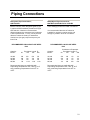
Piping Connections
Refrigerant Pipe Connections;
AIR-COOLED
When piping air-cooled systems, care must be
taken to use only clean refrigerant grade (Type
L) pipe and follow standard procedures for pipe
size selection. Maximum recommended
distance between the evaporator and condenser
is 200 equivalent feet. For any run beyond this
distance contact the factory for assistance.
Vertical runs (hot gas) require a trap every 20
feet of rise.
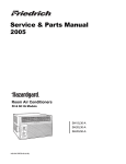
RECOMMENDED DISCHARGE LINE SIZES
R-22
Capacity
BTU/hr
50
18,000
24,000
36,000
60,000
5/8
5/8
7/8
7/8
Equivalent Length, Ft.
100
150
200
5/8
7/8
7/8
1-1/8
5/8
7/8
7/8
1-1/8
7/8
7/8
7/8
1-1/8
Recommended sizes are applicable with
o
o
evaporating temperatures from -40 F to 45 F
o
and condensing temperatures from 80 F to
o
130 F.
Water/Glycol Pipe Connections;
WATER-COOLED/GLYCOL-COOLED
Care should be taken in the correct connection
of the water/glycol inlet and outlet connections.
It is recommended that shut off valves be
installed for use during routine service and
emergency isolation of the air conditioner.
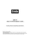
RECOMMENDED LIQUID LINE SIZES
R-22
Capacity
BTU/hr
Condenser to Evaporator
Equivalent Length, Ft.
50
100
150
200
18,000
24,000
36,000
60,000
3/8
3/8
1/2
1/2
3/8
1/2
1/2
5/8
1/2
1/2
1/2
5/8
1/2
1/2
1/2
5/8
Recommended sizes are applicable with
o
o
evaporating temperatures from -40 F to 45 F
o
and condensing temperatures from 80 F to
o
130 F.
10
Pre Start-Up
Prior to initial start-up, perform the following checks to ensure proper unit operation:
ELECTRICAL CHECKS
1. Check to make sure that incoming voltages
match the nameplate's phase and voltage
listings.
2. Make sure that the unit is properly grounded
to an earth ground.
3. Check all internal electrical components and
terminal blocks for loose connections, which
may have been caused by shipping
vibrations.
4. Check that all fuses are correct and securely
in the fuse blocks.
5. Check the blower motor overload for correct
setting (FLA of motor on motor nameplate)
and make sure that the overload has not
been tripped.
MECHANICAL CHECKS
1. Make sure that all direct expansion and
water/glycol isolation valves are open in the
system.
2. Check to make sure that water/glycol will
flow through the unit for heat rejection.
3. Bleed any air from the unit’s cooling system
using the internally mounted Schrader
valves.
4. Check for water leaks at the humidifier
connections.
5. Make sure that the blower belts are adjusted
correctly.
6. Before replacing the unit’s panels, make
sure that the inside of the unit, especially the
blower wheels, is free from debris.
7. Make sure that the air filters are in place and
clean.
When all of these checks have been performed,
replace and secure all of the unit's panels
Start-Up
After all mechanical and electrical service connections have been made and checked, start the unit as
follows:
alphanumerical messages for the unit’s
1. Make sure that the power switch is in the
mode of operation.
OFF position and apply power to the unit.
5. The operation of the unit must be checked
Turn unit disconnect switch to the ON
thoroughly. To accomplish this, the set
position (if applicable) and verify that line
points on the controller must be set to
voltage is as specified on the unit
extreme conditions. Before checking
nameplate. Check the control transformer
extreme points, the computer equipment
secondary voltage. This voltage should be a
(heat load) must be installed. Depending on
normal 24 volts, no higher than 26.5 volts
the temperature and humidity in the space at
and no lower than 23 volts.
the time of installation, check either the
2. Check for proper rotation of the blower
stages of heating or cooling, or
motors. If rotation is incorrect, depress
humidification or dehumidification modes.
power switch to turn the unit off and shut off
6. Humidification or dehumidification can be
the main power at the source disconnect.
checked by changing the humidity set point
Interchange any two of the three main line
in a similar manner.
power leads to the power distribution block
7. Check that all safety alarms and controls
in the unit. Return to step one.
function properly.
3. Acknowledge any alarms that appear on the
Complete the start-up sheet and return it to
display at the controller’s prompts. The
APC.
alarms are usually power loss, high or low
temperature and high or low humidity.
4. The controller will energize heat, cool,
humidification, or dehumidification circuits as
required and display the appropriate
11
Charging the System
The AFX Series Water/Glycol and the integral
mounted Air-cooled systems are factory charged
with refrigerant. All other direct expansion
systems must have the piping evacuated and
the system charged.
All refrigerant connections should be leak tested
before the system is charged with refrigerant.
The complete system should be pressured to
400 psig with refrigerant and dry nitrogen. Use
an electronic leak detector to carefully check
each joint. Leaks should be repaired and the
system pressurized again to 400 psig to double
check all joints.
After the leak check has been performed, a
vacuum pump should be used to evacuate the
total system (the unit, condenser and interconnecting piping) after the condenser has been
installed in the system. Put vacuum on the total
system of 29 inches or 50 microhms and hold it
for four hours. Then break the vacuum with dry
refrigerant. At this point the system can be fully
charged.
Follow standard HVAC charging practices but
use the following recommendations: when the
system is properly charged, the superheat
o
should be nominally 15 F and the subcooling
o
10 F.
System Function
After connecting all the utilities to the unit and
ensuring that the unit is securely mounted in
place, start the air conditioner by enabling the
ON/OFF switch on the thermostat in the ON
position. This will start the evaporator blower.
Turn the thermostat to the lowest setting and the
compressor will start. After the refrigeration
system has functioned for approximately 15
minutes, observe the suction and discharge
pressure gauges and inspect
the sight glass. The system should be fully
charged (sight glass clear). The gauges should
indicate between 58-75 psig suction pressure
and approximately 225-275 psig discharge
pressure. If the unit is functioning properly, the
controls may be set at the desired setting and
the return air grille closed.
Complete the start-up sheet and return it to
APC.
12
Control/Safety Adjustments
After the installation and start-up of the AFX
Series unit has been completed, "fine tuning"
of the system's controls and safety systems is
necessary, as described below.
Belt Tension
The blower motor is mounted on an adjustable
base. Belt tension can be increased or
decreased by raising or lowering the base.
A deflection of about 3/4 - 1" per foot of span
between the blower and motor pulleys should be
obtained by pressing the belt firmly. The
adjusting belt should be locked in position after
adjustment is made.
WARNING
Too much tension will shorten bearing,
shaft and belt life.
For quiet operation, the belt should be as loose
as possible without slippage. Slippage may
result in belt squeal or insufficient airflow, or
both. A simple test for the belt slippage is to
check the temperature of the smaller pulley in
relation to the larger pulley. If the small pulley is
noticeably warmer, this is an indication of belt
slippage and the belt should be tightened
slightly. Do not test temperature while pulleys
are turning.
Belt tension should be readjusted if the variable
speed pulley setting is changed or if the belt is
replaced.
Motor Pulley
The pulley on the blower motor has a variable
pitch diameter to allow the blowers to be sped
up or slowed down to compensate for higher or
lower external static pressure, or in some cases,
high altitude compensation.
The motor pulley has been factory sized and the
unit has been factory tested with the pitch in the
middle of its adjustment range.
13
To increase blower speed, remove the belt from
the pulley by taking it off the larger nonadjustable blower pulley first. Loosen the set
screw on both movable sheaves. Turn them
inward toward the center stationary sheave to
increase the effective pitch diameter. To
decrease the blower speed, spread the sheaves
further apart.
Turn both sheaves the same number of times.
This is necessary to maintain uniform tension on
both belts.
Tighten the set screws again, making sure that
they are not on the threaded portion of the
sheave, and put the belts back on.
Check for proper alignment between the driving
and driven sheaves (pulleys). Improper
alignment will cause premature wear on the
blower belts.
Air Pressure Differential (optional)
The CM unit uses an APD switch to sense
airflow loss through the unit. The APD is factory
set to make the switch close at 0.2" W.G. across
the internal APD bellows. The pressure setting
is adjustable by turning the adjustment screw
clockwise to increase the setting.
Clogged Filter Switch (optional)
The clogged filter switch senses the air pressure
drop across the filters. When the pressure drop
is too high due to dirty filters, the switch closes
and causes an alarm. While the clogged filter
switch has been set at the factory for
approximately 1.0 of pressure drop across the
filters, the setting should be checked at unit
start-up. Cover one-third of the filter area and
increase or decrease the clogged filter switch
sensitivity so that the switch closes when onethird of the filter area is blocked. This procedure
can only be used with new, clean filters.
Control/Safety Adjustments
OVERLOAD RELAY
The blower motor starter has an adjustable
overload relay. The adjustment dial should be
set to correspond to the full load amperes (FLA)
on the blower motor. The overload has a
manual reset button to prevent the motor from
cycling on the overload switch.
FIRESTAT
The firestat used in this unit has a manual reset
and an adjustable temperature setting. The
firestat is factory set prior to shipment to trip
when temperatures above 125?F are detected.
FLOW SWITCH
If the unit is equipped with a flow switch, the
sensitivity of the switch must be adjusted for the
flow amount. Failure to do so will cause false
alarms to occur.
14
Humidifier Operation
Your AFX Series unit may be equipped with a
pure steam generator type humidifier as an
option.
Check all electrical connections for wires, which
may have become loose in shipping.
Components burnt due to loose connections are
NOT covered under warranty.
Check electrode plugs to ensure they are
pressed firmly onto the electrode pins.
Important: Loose connections will cause
overheating of the cylinder plugs and probable
melting of the plugs and/or cylinder.
Turn on the main disconnect in the primary
service feeding the unit and check that the unit
has power at the primary terminal block.
On the humidifier controller attached to the left
side of the humidifier assembly, push the black
switch to "AUTO/ON" so that it clicks into the
depressed position.
Water will start to enter the cylinder through its
bottom port and rise in the cylinder to a point
determined by the solid state control circuitry.
It is not unusual upon initial start-up for water to
fill the cylinder and cycle on the red change
cylinder light. The high level probe simply acts
as a safety to shut off the fill valve and prevent
overfilling. With the red light on, the water in the
cylinder will continue to heat and after a few
minutes start to boil. After the boiling action of
the water has lowered the water level below the
sensor at the top of the cylinder, the
15
red light will go out and the fill solenoid will again
open until the cylinder is again full. This cycling
of the red light and fill valve will continue until
the unit's full output capacity is reached, after
which the water level will automatically lower
itself in the cylinder. (The increased mineral
concentration allows for lower electrode
coverage while maintaining the same stream
output.) When a stabilized condition is reached,
the water will be boiling close to the cylinder
seam level. The solid state circuitry will maintain
the proper concentration in the cylinder by
introducing short drains only when necessary. If
the cylinder is manually drained, the above
process will repeat itself.
NOTE: The AFX Series unit must be in the
humidification mode to fill or to manually drain.
Areas with Low Water Conductivity
Should normalization of the unit be required
immediately after start-up, the installer may
speed up the process by artificially increasing
water conductivity. The installer should dissolve
not more than half a teaspoon of table salt in a
cup of water and add it to the cylinder by means
of the fill cup attached to the plumbing section
during a fill cycle.
Excessive amounts of salt will result in erratic
operation of the unit; however, normalization of
the unit will be obtained automatically through
the solid state control sequence.
For further information, consult the Humidifier
Operation and Maintenance Manual included
with each unit equipped with a humidifier.
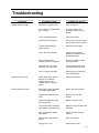
Troubleshooting
PROBLEM
POSSIBLE CAUSE
CORRECTIVE ACTION
Controls erratic or inoperative
Wiring improperly connected
or broken.
Check wiring connections at
schematic.
Evaporator coil ices
Usually caused by lack of
proper quantity of airflow
across coil.
Check filters; clean if
necessary.
Check for obstruction of
airflow in duct system. Unit is
designed for ½” s.p. (ext.)
W.P. approximate.
Low return air temperature.
Ensure correct rotation of
evaporator blowers.
Check return air temperature
setpoint.
Blower fails to start
Compressor fails to start.
Low refrigerant.
Check DX system for correct
operation/leaks.
Power failure.
Check power source and
input cable.
Control circuit fuse blown.
Replace fuse.
Defective contactor.
Repair or replace.
Overload tripped.
Reset and check cause.
Controller alarm.
Clear alarm(s).
Setpoint too high.
None required. Adjust to
desired temperature. Check
compressor electrical circuit
for shorts or loss of phase.
Complete loss of refrigerant
charge.
Repair leak and recharge
system.
Head pressure too high (high
pressure switch open).
Check condenser for
obstructions. Manually reset
switch.
Liquid line solenoid not
opening.
Check for 24 VAC to solenoid
coil. If not, check wiring. If 24
VAC is at solenoid, solenoid
coil may be bad, or is stuck.
Replace or repair as
necessary.
Controller alarm.
Clear alarms.
16
Troubleshooting
PROBLEM
Compressor short cycles.
Noisy compressor.
System short of capacity.
17
POSSIBLE CAUSE
CORRECTIVE ACTION
Low line voltage causing
compressor electric motor to
overheat.
Check power source for
cause of variation of line
voltage.
Dirty or icy evaporator
(reduce air flow).
Defrost and/or clean.
Lack of refrigerant (bubbly
sight glass).
Repair leak and recharge
system.
Light load.
Configure controller for light
load.
Defective LP switch
Check and/or replace.
Expansion valve stuck in
open position (abnormally
cold suction line).
Ensure feeler bulb is tight on
suction line. Check operation
and superheat.
Broken compressor valve.
Replace compressor.
Worn or scarred compressor
bearings (excessive
knocking).
Replace compressor.
Excessive head pressure
(compressor knocks).
Reduce head pressure.
Flash gas in liquid refrigerant
line (bubbly sight glass).
Repair leak and recharge.
Expansion valve stuck or
possibly obstructed (short
cycling or continuous
running).
Replace valve.
Clogged drier-strainer (feels
cold).
Replace with new drierstrainer.
Ice or dirt on evaporator coil
(excessively warm air from
evaporator blower). See
Evaporator coil ices section
above.
Defrost and/or clean.
Troubleshooting
PROBLEM
Head pressure too high.
POSSIBLE CAUSE
CORRECTIVE ACTION
Condenser clogged or dirty.
Clean condenser.
Air or other non-condensable
gas in system
Evacuate system and
recharge. Install new drier
strainer.
O.H.E. air intake blocked.
Clean away debris.
Overcharge of refrigerant.
Purge or remove excess from
high pressure side of system
Pump overloads tripped
(glycol system).
Reset and check cause.
O.H.E. fans not operating.
Check fuses and motor.
Replace as needed. Check
thermostat setting.
Glycol head pressure
regulating valve not adjusted.
Adjust as needed to obtain
correct pressures.
Glycol flow too low. Pump
cavitating, valve not open.
Check glycol solution level
and concentration at pump.
Glycol % higher than 40%.
Reduce glycol to maximum
40% concentration.
Head pressure too low.
Check water valve. Check
settings on condenser
ambient sensors. See
“System short of capacity”
above.
Correct as indicated.
Suction pressure too low.
Flash gas in liquid refrigerant
line (bubbly sight glass).
Repair leak and recharge.
Clogged drier strainer (feels
cold).
Replace with new drier
strainer.
Obstructed expansion valve
(loss of capacity).
Repair or replace valve.
Loss of fluid within expansion
valve (erratic valve response)
Replace valve and feeler bulb
assembly.
Lack of refrigerant (bubbly
sight glass)
Repair leak and recharge
system.
Dirty air filters/clogged filter
light on.
Clean as required.
Clogged or icy coil.
Defrost and/or clean.
18
Troubleshooting
PROBLEM
Humidifier inoperative.
Reheat elements inoperative.
Water carryover.
POSSIBLE CAUSE
CORRECTIVE ACTION
Water not hooked up.
Turn on water.
Electrical connections loose.
Tighten electrical connections
Humidifier fuse open.
Check for short circuit.
Replace if necessary.
Relative humidity is above
the setpoint.
No corrective action needed.
Overheat switch actuated.
Reset and check.
Fuse open.
Check for short circuit.
Replace if necessary.
Thermostat set too low.
None required. Adjust to
required temperature.
Thermal line in heater open.
Replace line.
Insufficient air quantity over
the evaporator coil.
Load fan to name plate
AMPS. Remove discharge air
restrictions. Clean filters.
Liquid line temperature.
Adjust condensing
temperature to specifications
and reduce excessive
subcooling.
Dirty coil.
Clean the coil.
Excessive air.
Reduce CFM.
No power to controller.
Check control fuse.
Controller fails to start.
19
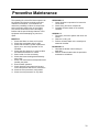
Preventive Maintenance
The operating life of the AFX Series system can
be extended by following a simple preventive
maintenance schedule. The schedule will
reduce the possibility of failure of components
and unnecessary malfunction of the system.
The service technicians must be thoroughly
familiar with the special design features of this
equipment before attempting any service or
repair.
MONTHLY
1. Check that filters are clean and in place.
2. Check that condensate drain is open.
3. Check that humidifier cylinder replacement
light it not on and verify operation of the
humidifier.
4. Check that drive belts are in good condition
and that the belt tension is correct.
5. Clean inside of unit as necessary.
6. Check that blower bearing/shaft assembly
turns freely.
7. Check unit conformance to temperature and
humidity set points.
8. Ensure heater operation.
9. Check electrical components and ensure
correct amp draws and secure connections.
10. Check the microprocessor configuration.
11. Check the microprocessor for any alarm.
SEASONALLY
1. Check electrical components for loose wire
connections.
2. Check fan(s) and drive components.
3. Complete all items listed on the monthly
checklist.
ANNUALLY
1. Thoroughly check the system and clean unit
interior.
2. Clean the cooling coil.
3. Perform all items listed on the monthly and
seasonal checklist.
BI-ANNUALLY
1. Lubricate the blower motor bearings if
applicable.
2. Perform all items listed under the preventive
maintenance schedules.
20
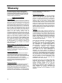
Warranty
The limited warranty provided by American Power
Conversion Corporation ("APC") in this Statement of
Limited Factory Warranty applies only to Products you
purchase for your commercial or industrial use in the
ordinary course of your business.
LIMITED FACTORY WARRANTY
Terms of Warranty:
APC warrants that the Product shall be free from defects in
materials and workmanship, for a period of (1) year from the
date of start-up when APC authorized service personnel has
performed the start-up of the Product, or a maximum 18
months from the date of Product shipment from APC, when
APC authorized service personnel has not performed the
start-up of the Product (“Warranty Period”.) In the event that
the Product fails to meet the foregoing warranty, APC shall
repair or replace any defective parts, such repair or
replacement to be without charge for on-site labor and travel
if APC authorize personnel have conducted start-up of the
Product.
An
APC
Start-Up
Service
must
be
performed/completed by APC authorized service personnel
or replacement of defective parts only will be covered. APC
shall have no liability and no obligation to repair the installed
Product if non-authorized APC personnel performed the
start-up and such start-up caused the Product to be
defective. Any parts furnished under this warranty may be
new or factory remanufactured. THIS WARRANTY DOES
NOT COVER circuit breaker resetting, loss of refrigerant,
consumables, or preventative maintenance items. REPAIR
OR REPLACEMENT OF A DEFECTIVE PRODUCT OR
PART THEREOF DOES NOT EXTEND THE ORIGINAL
WARRANTY PERIOD.
Warranty Extends to First Purchaser for Use, Nontransferable:
This Warranty is extended to the first person, firm,
association or corporation for whom the APC Product
specified herein (herein referred to as "You or Your".) This
Warranty is not transferable or assignable without the prior
written permission of APC.
Assignment of Warranties:
APC will assign to you any warranties which are made by
manufacturers and suppliers of components of the APC
Product and which are assignable. Any such warranties are
assigned "AS IS" and APC makes NO REPRESENTATIONS
as to the effectiveness or extent of such warranties,
assumes NO RESPONSIBILITY for any matters which may
be warranted by such manufacturers or suppliers and
extends no coverage under this Warranty to such
components.
Drawings, Descriptions:
APC warrants for the Warranty Period and on the terms of
the Warranty set forth herein that the APC Product will
substantially conform to the descriptions contained in APC's
Official Published Specifications or any the drawings certified
and agreed to by an authorized APC representative, if
applicable thereto (“Specifications”). It is understood that the
Specifications are NOT WARRANTIES OF PERFORMANCE
21
and NOT WARRANTIES OF FITNESS FOR A
PARTICULAR PURPOSE.
Warranty Claims Procedure:
To obtain service under Warranty contact APC Customer
Support at (800) 800-4APC. You will need the model
number of the Product, the serial number, and the date
purchased. A technician will also ask you to describe the
problem. If it is determined that the Product will need to be
returned to APC you must obtain a returned material
authorization (RMA) number from APC Customer Support.
Products that must be returned, must have the RMA number
marked on the outside of the package, and be returned with
transportation charges prepaid. If it is determined by APC
Customer Support that on-site repair of the Product is
allowed, APC will arrange to have APC authorized service
personnel dispatched to the Product location for repair or
replacement, in APC's discretion.
Exclusions
APC SHALL NOT BE LIABLE UNDER THE WARRANTY IF
ITS TESTING AND EXAMINATION DISCLOSE THAT THE
ALLEGED DEFECT IN THE PRODUCT DOES NOT EXIST
OR WAS CAUSED BY YOUR OR ANY THIRD PERSON’S
MISUSE, NEGLIGENCE, IMPROPER INSTALLATION OR
TESTING, UNAUTHORIZED ATTEMPTS TO REPAIR OR
MODIFY, OR ANY OTHER CAUSE BEYOND THE RANGE
OF THE INTENDED USE, OR BY ACCIDENT, FIRE,
LIGHTNING OR OTHER HAZARD.
THERE ARE NO WARRANTIES, EXPRESS OR IMPLIED,
BY OPERATION OF LAW OR OTHERWISE, OF
PRODUCTS SOLD, SERVICED OR FURNISHED UNDER
THIS AGREEMENT OR IN CONNECTION HEREWITH.
APC DISCLAIMS ALL IMPLIED WARRANTIES OF
MERCHANTABILITY, SATISFACTION AND FITNESS FOR
A
PARTICULAR
PURPOSE.
APC’S
EXPRESS
WARRANTIES WILL NOT BE ENLARGED, DIMINISHED,
OR AFFECTED BY AND NO OBLIGATION OR LIABILITY
WILL ARISE OUT OF, APC’S RENDERING OF
TECHNICAL OR OTHER ADVICE OR SERVICE IN
CONNECTION WITH THE PRODUCTS. THE FOREGOING
WARRANTIES AND REMEDIES ARE EXCLUSIVE AND IN
LIEU OF ALL OTHER WARRANTIES AND REMEDIES.
THE WARRANTIES SET FORTH ABOVE, CONSTITUTE
APC’S SOLE LIABILITY AND YOUR EXCLUSIVE REMEDY
FOR ANY BREACH OF SUCH WARRANTIES. APC’S
WARRANTIES RUN ONLY TO YOU AND ARE NOT
EXTENDED TO ANY THIRD PARTIES.
IN NO EVENT SHALL APC, ITS OFFICERS, DIRECTORS,
AFFILIATES OR EMPLOYEES BE LIABLE FOR ANY
FORM OF INDIRECT, SPECIAL, CONSEQUENTIAL OR
PUNITIVE DAMAGES, ARISING OUT OF THE USE,
SERVICE OR INSTALLATION, OF THE PRODUCTS,
WHETHER SUCH DAMAGES ARISE IN CONTRACT OR
TORT, IRRESPECTIVE OF FAULT, NEGLIGENCE OR
STRICT LIABILITY OR WHETHER APC HAS BEEN
ADVISED IN ADVANCE OF THE POSSIBILITY OF SUCH
DAMAGES.
990-7401B
22