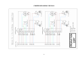
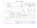
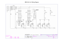
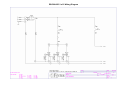
1
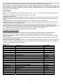
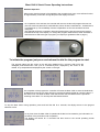
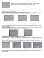
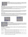
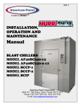
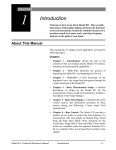
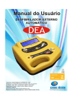
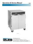
RBC20-60
Blast Chiller
Contents
Page
Introduction
Model Details
Controller Technical Detail
Parts List
Operating Instructions
Electrical Connections
Service Information
Diagnostics
Function Test
Passcode
Profiles
Parameter Access
Parameters
Parameter Definitions
Alarms and Warnings
Foot Print Test Operation
Probes
Technical Data
Wiring Diagrams
1 to 2
2
2
2
3 to 6
7
7 to 19
8
8
8
9
9
9 to 11
11 to 18
18
19
19
20 to 22
23 to
Introduction.
Cook Chill Operation.
Blast chilling is a process to reduce the temperature of cooked food by swiftly arresting the cooking process, locking in its
colour, flavour, texture and nutritional value. Department of health guidelines state that to safely blast chill food the
temperature must be reduced from +70°c to +3°c within 90 minutes.
Pre Chill
Pre chilling ensures the correct cabinet temperature in the unit before chilling commences therefore improving the chilling
performance.
Soft Chilling.
Soft chilling is the process of rapid but gentle chilling of food.
This cycle brings down the food temperature to +3°c in no more than 90 minutes without the air or food temperature going
below 0°c.
This prevents large ice crystals forming therefore maintaining the texture, consistency and appearance of food such as
vegetables, rice, pasta, custard and fruit with no dehydration or cell damage.
Hard Chilling.
Hard chilling is the process of general purpose chilling.
This cycle brings down the food temperature to +3°c in no more than 90 minutes and is ideal for chilling meat pies,
lasagne, pasta and individually portioned meals. The air temperature for this process goes down to -15°c for the first 70%
of the cycle, to extract the maximum amount of heat from the product quickly. The air temperature then increases to +3°c
for the final 30% of the time to reduce surface damage and ensure quality.
Hard Chill Max.
Hard chill max brings down the food temperature to +3°c in no more than 90 minutes and is used for chilling high density
or high fat content food such as meat joints, stews or packaged products.
The air temperature during the cycle is allowed to go down to -20°c.
After either a pre-designated time has elapsed or product temperature has been achieved, the air temperature is allowed
to rise to the ‘hold’ value with the temperature being maintained at this level indefinitely.
Surface Protection.
Removing the heat energy from food product as rapidly as possible by the combination of powerful refrigeration and
evaporator fans moving large volumes of cooled air can cause damage to the food product. The food product could have
a form of ‘Frost Burn’ caused by the fast moving air feeling cooler than the actual air temperature ‘Wind Chill Effect’. This
may lead to product discoloration, dehydration, localised freezing and spoilage of the food product.
Surface protection overcomes this by reducing the evaporation operation, and hence the air speed at pre-determined
stages in the cycle to ensure that this does not happen. This is a discreet function and happens automatically without any
intervention from the operator. To enable the surface protection; and determine at what stage it would be activated values
are set in the service operating parameters.
Longer Term Storage – ‘Hold’ Mode (Conservation)
Upon the completion of the blast chilling cycle the controller will automatically enter the ‘Hold’ mode. This will either be
because the selection set time has elapsed or the product core temperature has been achieved. When the hold period
commences an alarm will sound for a period denoted in the service operating parameters.
1
The controller will determine the temperature to be maintained during the hold phase based on the chilling cycle that has
been completed. If a soft or hard chill has taken place the controller will maintain an air temperature of 2°c.
The hold mode is principally intended as a temporary storage facility offering the operator flexibility until the product can
be unloaded into a longer term storage units at the correct storage temperature. On occasion this hold period may
become extended to operate overnight or to provide emergency refrigeration backup. In such instances defrosting would
automatically occur as necessary.
Model Details.
The RBC 20-60 is capable of blast chilling 60kg of product from +70°c to +3°c in 90 minutes with entry temperature up to
90°c
The cabinet is compatible with the Rational 20 rack GN 1/1 201 trolley.
Refrigerant used is R404A.
The RBC20-60 has two separate refrigeration systems comprising, two condensing units, a twin circuit condenser and a
twin circuit evaporator. (See pages 20 and 21 for assembly details and page 22 for schematic dual circuit refrigeration
layout).
The RBC20-60R has the same refrigeration systems but the condensing units are remotely sited.
Refrigerant control is by expansion valve to control the correct amount of refrigerant required to meet the demand of the
evaporator. (See page 21 for assembly detail).
The parameter ‘Capacity Enable’ is set to ‘ON’ to allow for both condensing units to be running during the chill cycle
therefore maximising the heat extraction from the product. During the ‘HOLD’ mode with the ‘Capacity Enable’ set to ‘ON’
one compressor will control the temperature throughout unless the temperature exceeds the capacity control limit.
A 1½” BSP drain outlet is fitted in to the base of the cabinet for connection to external drain.
The cabinet is delivered with the legs secured to the base of the cabinet.
Controller Technical Detail
The FCC controller is a three-piece unit made up of the Front Display and Dial Shaft Encoder, Mother Board plus
Evaporator, Food and Air temperature probes. The front display PCB and the CPU/ Switching PCB unit are
interconnected by a ribbon cable. The membrane attached to the front provides an IP rating of IP54 providing a scratch
free wipe clean finish.
The control dial is the method by which the controller is accessed for all requirements. It has three planes of movement,
clockwise, anticlockwise and inwards.
The control dial allows the operator/ engineer to move forward and backwards through various menu selections shown on
the display, and enter a desired programme. The control system will then respond appropriately either commencing the
operating cycle or allowing further configuration.
Part numbers
Item
Controller Mother Board
Controller Shaft Encoder
Controller LCD Display
Air Probe P1
Evaporator Probe P2
Food Probe
Compressor x 2
Condenser Coil
Condenser Fan Assembly
Sight Glass
Drier
Solenoid Valve
Liquid Receiver
LP Switch
HP Switch
High Pressure Thermostat
Evaporator Coil
Expansion Valve
Orifice
Expansion Valve
Evaporator Fan Motor
hinge
Door Gasket
Door Switch
Door Switch Magnet
Door Handle
Description
NTC type. 2.5m
NTC type. 2.5m
5M Length
TAJ4519ZH T 400/50
BC6013/122
S4E300-BP26-30
3/8"
EVR6 32F5219+0
2.5 Bar 0.5 Bar Diff
28 Bar – 3 Bar Diff
KP5 Auto Re-set (set at 18 BAR with a 3 BAR diff.)
BC6013/121
Valve Body TES2-NL68Z34300/68
NO 02 68-2092/68-2072
Solder Adaptor 68-2
W4E420-CP02-66788-4-7320
Edgemount
1406x546MM
Circular (Reed Type)
Circular
Edgemount Latch Kit
2
Part Number
00-555395
00-555396
00-555394
00-555397
00-555397
00-555663
00-555885
01-257300-01
00-555886
15483015
00-555388
15451215
00-555579
00-555387
00-555386
15452109
01-256400-01
15450386
15451104
15450910
00-555375
00-555880
01-256387-01
00-555829
00-555828
00-555881
Blast Chill & Shock Freeze Operating Instructions.
Standard Operation
When mains electrical power is first applied to the controller it will carry out a self-test function,
for approximately 3 seconds. During this period the display will show.
On completion of the self test, the controller will revert to the last chill program that was run
(Pre-chill, Soft Chill, Hard Chill, Hard Chill Max, Shock Freeze, Professional 1, Professional 2,
or Professional 3). The availability of these is dependent on how the controller has been
configured.
The example shows the controller in Hard Chill mode with the previous and next programs
indicated at the top of the display. To change the program rotate the dial, either clockwise or
anticlockwise to select the type of program you require.(for guidelines refer to page 7)
To initiate the program just press and release the dial for the program to start.
The program starts with the screen on the left being displayed for 2 minutes. After which the
intelligent probe determines if the cycle is controlled by time, displayed by the screen in the
middle, or by temperature as displayed by the screen on the right.
On completion of the program the controller will cause the blast chiller to enter the Hold Mode,
as displayed on the left. An alarm will sound, press and release the dial to cancel the alarm, if
the alarm is not cancelled the blast chiller will still enter the Hold Mode with the periodical
sounding of the alarm. To cancel press and release the dial.
To stop the blast chiller during operation, press and hold the dial for 2 seconds, the display returns to the program
selection screen.
At any time when the blast chiller is operational the dial can be rotated to give information on
the status of the particular mode of operation.
The display will remain for 10 seconds and then revert to the normal operating screen
automatically.
3
Pre Chill
This program is used to Pre Chill the cabinet prior to the first cycle. This is done with the
Blast Chiller empty and is a short time based program of about 20 minutes.
It is generally recognised as the correct method of preparing for a blast chill cycle.
The program is selected by rotating the dial until the display shows, press and release the dial
to start the program.
Defrost.
Defrosting is not normally required but if there is an ice build up on the coil inside the cabinet a manual defrost can be
selected. Rotate the dial until the Defrost screen, below left, is displayed.
Press and release the dial to start the defrost.
During defrost the screens will alternate between the middle and right hand screens.
Defrost will last 20 minutes and when completed the alarm will sound. Press the dial to acknowledged or if not wait until it
comes to the end of the alarm period, the alarm will stop and the display will revert to the previous screen.
Further Operational Features.
Chill time adjustment. (All programs excluding Professional 1, 2 or 3)
Whilst in the pre-programmed selection screen press and hold the dial for 2 seconds, the information screen will be
displayed, below left. Press and release the dial to move to the time set, see below right. Rotate the dial clockwise to
increase the time, anticlockwise to decrease. Once the time has been selected, press and release the dial and ‘CHILL
TEMP’ will be highlighted.
On completion press and hold the dial for 2 seconds to return to the program selection screen, to continue press and
release the dial for the program to start.
On completion of the program the time changes will revert to the default settings.
Chill / Hold temperature adjustments. (Professional 1, 2 or 3 only)
Professional 1, 2 and 3, if configured, are programs that can be used to tailor the chill time and temperature to suit
specific product requirements.
Adjust the ‘CHILL TIME’ as above. With the ‘CHILL TEMP’ highlighted, below second from the left, press and release the
dial to move to the temp set, below second from the right. Rotate the dial clockwise to increase the time, anticlockwise to
decrease. Once the time has been selected, press and release the dial and ‘HOLD TEMP’ will be highlighted. Follow the
procedure for changing chill temp to change the hold temp.
On completion press and hold the dial for 2 seconds to return to the program selection screen, to continue press and
release the dial for the program to start.
The chill time and chill / hold temperature adjusted settings are retained for professional 1, 2 and 3 programs and will not
revert to the default.
4
Information
Whilst in the program selection screen press and hold the dial for 2 seconds, the information
screen will be displayed. Rotate the dial until ‘INFORMATION’ is highlighted. Press and
release the dial to display the screen showing the last run cycle. The information relates to
date, program run, start time, start temperature and end temperature.
HACCP settings.
Whilst in the program selection screen press and hold the dial for 2 seconds, the information screen will be displayed.
Rotate the dial until ‘HACCP SETTINGS’ is highlighted. Press and release the dial to access the HACCP option screen.
Press and release the dial to move to the selection screen for long or short reports, rotate the dial to select which option,
once selected press and release the dial to confirm.
Press and release the dial to move to the selection screen for the print sample, select 3 or 5 minute selection rate.
On completion press and hold the dial for 2 seconds to return to the program selection screen.
Print Data.
Whilst in the program selection screen press and hold the dial for 2 seconds, the information screen will be displayed.
Rotate the dial until ‘PRINT DATA’ is highlighted. If using a hand held printer switch the printer on now. Point the printer at
the infra red download sensor (optional), located in display area, press and release the dial to download the print data.
On completion press and hold the dial for 2 seconds to return to the program selection screen.
Set time and date.
Whilst in the program selection screen press and hold the dial for 2 seconds, the information screen will be displayed,
below left. Rotate the dial until ‘SET TIME/DATE’ is highlighted. Press and release the dial to access the service screen,
below right. Press and release the dial to move to the displayed time in hours and minutes, rotate the dial to alter the time,
once the correct time has been achieved press and release the dial to move to ‘DAY’. If it is necessary to change the day,
month and year change the settings using the same procedure for setting the time.
On completion press and hold the dial for 2 seconds to return to the program selection screen.
Changing Text Language.
Whilst in the program selection screen press and hold the dial for 2 seconds, the
information screen will be displayed continue pressing the dial for a further 2 seconds to
display the ‘SERVICE MENU’. LANGUAGE will be highlighted, press and release the dial,
‘ENG’ (English) will be highlighted. Rotate the dial to change the language. Select the
preferred language, press and release the dial to confirm.
Screen Saver
The screen saver screen is displayed if the machine is not used for 20 minutes, providing power is connected to it. It
shows a series of ‘Z’ indicating sleep mode. Pressing and releasing the dial or opening the door will awaken the unit, the
program selection screen will be displayed.
Alarms and Warnings
Air Probe:
If this alarm occurs it will remain in the program selected until it is completed, however no further
operation will be possible. Call your Foster Authorised Service Company.
Evap Probe:
If this alarm occurs it will remain in the program selected until it is completed, however no further
operation will be possible. Call your Foster Authorised Service Company.
Food Probe:
If this alarm occurs it will automatically change to a timed program until it is completed, however no
further operation will be possible. Call your Foster Authorised Service Company.
Door Open:
The display will continue to show the alarm message until the door is closed. If this does not cancel the
alarm call your Foster Authorised Service Company.
5
High Temperature: This alarm will only occur in the hold mode only. Probe the product to determine it is at the correct
temperature. If it is at the correct temperature place in a storage refrigerator or freezer and call your
Foster Authorised Service Company. If the product temperature is above the guidelines check the chill
time selected or the weight of product being chilled does not exceed the specification for the Cabinet.
HP Switch:
Causes for this alarm could be:
Does the product temperature exceed 90°c. Has too much product been placed in the cabinet. Is the
airflow restricted. Does the condenser filter require cleaning. If the problem persists call your Foster
Authorised Service Company.
Power Fail:
If the power fails for up to five minutes the unit will re-start on the resumption of the power supply without
affecting the selected cycle. Longer than five minutes and the controller will enter the hold mode. To
check the cycle operation look in the information screen to check the cycle time.
To re-start press and release the dial, the screen will return to the hold screen. Press and hold the
dial for two seconds the display returns to the program selection.
There are Three main programmes RBC 20-60 Blast Chiller.
Soft Chill- for the safe chilling of delicate products such as gateaux and patisserie items, and high water content items
such as vegetables, rice and pasta.
Hard Chill- For general purpose chilling. The Hard Chill cycle is ideal for chilling ‘standard products’ such as meat pies,
lasagne, individually portioned meals etc. Providing surface protection for the later part of the program.
Hard Chill Max- For high density and high fat content products such as meat joints, stews and sous vide.
Guide for Blast Chilling.
Blast Chill
Programme
required
Time required
to Blast Chill
(Minutes)
Beef, pork, lamb, poultry & mince
Hard
40 - 90
Fish
Fried, poached or baked – haddock, plaice, salmon, cod
fillets etc
Soft
30 - 90
Prepared
dishes
Stews & casseroles, lasagne, risotto, shepherds pie
Hard
50 - 90
Vegetables &
Pulses
Steamed or roasted veg, rice and potatoes etc.
Soft
30 - 90
Fruit
Stewed and cooked fruits.
Soft
60 – 90
Bakery
Cakes
Hard
30 – 90
Bakery
Pastries
Hard
60 – 90
Desserts
Fruit Based desserts & egg based flans.
Soft
30 – 90
Desserts
Sponge puddings and dense desserts such as cheesecake.
Hard
30 – 90
Food Type
Includes
Meat
NOTE: All times listed should be used as a guide only, and will depend on type, size and quantity.
6
Electrical Connections.
Inputs.
L
N
E
-
Mains ‘Live’ supply (115V 230V, 50Hz / 60Hz). 4 terminals.
Mains ‘Neutral’ supply – 16 terminals.
Protective Earth – 16 terminals.
DOOR
DOOR2
HP
-
Door Switching connection (not voltage carrying).
Safety door switch connection (not voltage carrying).
High Pressure switch connection (not voltage carrying).
TA
TE
FP1
FP2
FP3
-
Air probe connection.
Evaporator probe connection.
Food/ product temperature connection.
Additional second food / product temperature probe connection.
Additional third food / product temperature probe connection.
Outputs.
C1
F1
F2
D1
S1
A1
P1
-
Condensing system switched relay (30A/ 8A) – normally open (NO) output – 3 terminals.
Evaporator fan 1 switch relay (8A/ 4A) – normally open (NO) output – 3 terminals.
Evaporator fan 2 switch relay (8A/ 4A) – normally open (NO) output – 3 terminals.
Defrost system switched relay (8A/ 4A) – normally open (NO) output – 3 terminals.
UV light system switched relay (8A/ 4A) – normally open (NO) output 2 terminals.
Alarm relay (8A/ 4A) normally closed (NC) – 1 terminal, normally open (NO) 2 terminals.
Capacity relay (8A/ 4A) normally closed (NC) – 1 terminal, normally open (NO) 2 terminals.
Display Power Display Data
Logger
-
Man Machine socket 2 – way connection.
Man Machine RJ54 Type 4 – way connection.
4 – way RS 485 connections.
Service Information
Refer to the operating instructions on page 4 for operating instructions.
When mains electrical power is first applied to the controller it will carry out a self test function, for approximately 3
seconds, to ensure that there are good connections between the component parts. During this period the display will
show.
The information displayed in the centre of the screen refers to which of the profiles the controller is set for.
The software version relates to the software release. The number relates to the major operating changes or model
variants. The letter relates to the minor operating changes that may have been made from the original, such as parameter
settings.
On completion of the self test the controller will revert to the last chill program that was run (Pre-chill, Soft Chill, Hard Chill,
Hard Chill Max, Shock Freeze, Professional 1, Professional 2, or Professional 3). The availability of these is dependent on
how the controller has been configured. The example below shows the controller in Hard Chill.
Press and hold the dial for 5 seconds.
Firstly the display will display the information page, below left, continue pressing until the ‘SERVICE’ screen is displayed,
below right. For changes to language see page 5.
7
Diagnostics
Rotate the dial until you reach ‘Diagnostics’, below left, press and release the dial to highlight the component. In this
program you can test each of the major components on the machine in sequence, 1- COMPRESSOR, 2-FAN1, 3-FAN2,
4- DEFROST, 5- ALARM, 6- CCAP (Capacity Control), 7- UV-L (UV light if fitted), ESC (escape). Rotate the dial until the
relay output is highlighted, once selected press and the dial to test the relay, the relay will remain energised for as long as
it is pressed. On completion of the test you must rotate the dial until you highlight ‘ESC’ press and release the dial to
move to the next program.
Function Test
Rotate the dial until you reach ‘FOOTPRINT’, see below, press and release the dial to initiate the controller function self
test.
This allows for the engineer to test the operation of the machine without having to wait for a full program to run. The test
lasts for ten minutes and should be carried out with the cabinet / room empty. Each of the relays will be energised to
simulate the chill process. Relay 1-COMPRESSOR, Relay 2-FAN1, Relay 3-FAN2, Relay 4-DEFROST, Relay 5-ALARM,
Relay 6-CCAP (Capacity Control), and Relay 7- UV-L will all be switched on and of automatically in a pre determined
manner to simulate program operation (whether they are connected or not).
The test is based around an algorithm built into the software. Prior to starting the program it is advisable to place a probe,
in the centre of the cabinet/room, attached to an independent measuring device to check the air temperature as the air,
coil and food probes are not active during this program. The temperature achieved will depend on the model. The air
temperature should be checked 5 to 6 minutes into the program. The temperature achieved should be the minimum
temperature and can be checked against the model type found in the parameter table on page 9. (For further information
go to page 19).
Once the test is completed the display reverts to the last chill program and not to the service parameters.
Passcode.
Rotate the dial until you reach ‘PASSCODE’, below left, press and release the dial to highlight the code, below right.
Rotate the dial until you reach the code ‘131’. Once achieved press and release the dial to acknowledge.
8
Profiles.
You are now in the program profiles. The controller has 9 operating programs – Pre Chill, Soft Chill, Hard Chill, Hard Chill
Max, Shock Freeze, Professional 1, Professional 2, Professional 3, Defrost and 2 optional programs – UV Sanitisation
and Information. These programs are all available depending upon which of the profiles are selected, see below.
To change the profile rotate the dial to select program, press and release the dial to accept the change. The 3 chevrons in
the box opposite the selected program confirm the change.
The default operating profile for the RBC20-60 and RBC20-60R is ‘LE CHEF’.
The table identifies which programs are available from the profile with ‘LE CHEF’ highlighted.
PROFILES
PROGRAMS
SIMPLE
SIMPLE +
CHEF
CHEF+
LE CHEF
EXPERT
EXPERT+
U
U
U
U
SOFT CHILL
U
U
HARD CHILL
9
9
HARD CHILL MAX
U
9
9
9
9
9
9
9
9
9
9
9
9
U
U
U
U
U
PROFESSIONAL 3
U
U
U
U
U
9
9
9
DEFROST
UV SANITISATION
INFORMATION
9
9
9
9
9
9
9
9
9
9
9
9
9
9
9
9
9
9
OPTIONAL
OPTIONAL
OPTIONAL
OPTIONAL
OPTIONAL
OPTIONAL
OPTIONAL
OPTIONAL
OPTIONAL
OPTIONAL
OPTIONAL
OPTIONAL
OPTIONAL
OPTIONAL
PRE CHILL
SHOCK FREEZE
PROFESSIONAL 1
PROFESSIONAL 2
9
U
U
U
U
U
U
U
U
U
U
Parameter Access.
From the profile screen once the selection has been made press and release the dial to access the parameter list. The
screen will display the parameters as shown in the screen below left. To access the system parameters rotate the dial
anticlockwise see below right.
Selection is made by pressing and releasing the dial.
The table below contains the complete parameter list and includes the selectable range and default values.
Parameters
PARAMETER
PO1
PO2
PO3
PO4
PO5
PO6
PO7
PO8
PO9
P10
P11
P12
P13
DESCRIPTION
PRE-CHILL
AIR TEMP
CHILL TIME
HOLD TEMP
SOFT-CHILL
AIR TEMP
CHILL TIME
CHILL TEMP
HOLD TEMP
HARD CHILL
AIR TEMP
CHILL TIME
CHILL TEMP
HOLD TEMP
CHANGE TIME
CHANGE TEMP
VALUE
MINIMUM
MAXIMUM
DEFAULT
°C
MINUTES
°C
-15
5
-10
15
60
15
-10
15
3
°C
MINUTES
°C
°C
-10
5
-5
-5
15
480
15
15
1
90
3
3
°C
MINUTES
°C
°C
%
%
-20
5
-15
-15
5
5
15
480
15
15
95
95
-15
90
3
3
80
80
9
P14
P15
P16
P17
P18
P19
P20
P21
P22
P23
P24
P25
P26
P27
P28
P29
P30
P31
P32
P33
P34
P35
P36
P37
P38
P39
P40
P41
P42
P43
P44
P45
P46
P47
P48
P49
P50
P51
P52
P53
P54
P55
P56
P57
P58
P59
P60
P61
P62
P63
P64
P65
P66
P67
P68
P69
P70
P71
P72
P73
P74
P75
P76
P77
P78
P79
P80
P81
P82
P83
P84
P85
HARD MAX
AIR TEMP
Chill Time
CHILL TEMP
HOLD TEMP
SHOCK FREEZE
AIR TEMP
CHILL TIME
CHILL TEMP
HOLD TEMP
PROFFESSIONAL 1
Air Temp. Std.
Chill Time Std.
Chill Time Minimum
Chill Time Maximum
Chill Temp. Std.
Chill Temp. Minimum
Chill Temp. Maximum
Hold Temp. Std.
Hold Temp. Minimum
Hold Temp. Maximum
Change Time
Change Temp.
PROFFESSIONAL 2
Air Temp. Std.
Chill Time Std.
Chill Time Minimum
Chill Time Maximum
Chill Temp. Std
Chill Temp. Minimum
Chill temp. Maximum
Hold Temp. Std.
Hold Temp. Minimum
Hold Temp. Maximum
Change Time
Change Temp.
PROFESSIONAL 3
Air Temp. Std.
Chill Time Std.
Chill Time Minimum
Chill Time Maximum
Chill Temp. Std.
Chill Temp. Minimum
Chill Temp. Maximum
Hold Temp. Std.
Hold Temp. Minimum
Hold Temp. Maximum
Change Time
Change Temp.
SYSTEM
UV Light Enable
HACCP Enable
Shock Chill Temp.
Chill Hysteresis
Hold Hysteresis
APM Time
APM Differential
FAN 1 Hold Operation
FAN 2 Hold Operation
Capacity Enable
Capacity Hysteresis
Defrost Type
Smart Defrost Inc
Defrost End Time
Defrost End Temp.
Drain Time.
Fan Delay Temp.
Duty Cycle
Comp. Rest Time
HP Switch
Door Switch 2
Door Switch 1
Door Stop
Door Alarm Delay
High Alarm Temp.
High Alarm Delay
Alarm Time
Alarm Repeat Interval
°C
MINUTES
°C
°C
-20
5
-15
-15
15
480
15
15
-15
90
3
3
°C
MINUTES
°C
°C
-35
5
-35
-35
15
480
15
15
-30
240
-21
-21
°C
Minutes
Minutes
Minutes
°C
°C
°C
°C
°C
°C
%
%
-20
P24
5
60
P27
-20
-5
P30
-10
0
5
5
15
P25
60
480
P28
-5
15
P31
0
10
95
95
-15
90
5
240
3
-10
5
3
0
10
80
80
°C
Minutes
Minutes
Minutes
°C
°C
°C
°C
°C
°C
%
%
-20
P36
5
60
P39
-20
-5
P42
-10
0
5
5
15
P37
60
480
P40
-5
15
P43
0
10
95
95
-15
90
5
240
3
-10
5
3
0
10
80
80
°C
Minutes
Minutes
Minutes
°C
°C
°C
°C
°C
°C
%
%
-20
P48
5
60
P51
-20
-5
P54
-10
0
5
5
15
P49
60
480
P52
-5
15
P55
0
10
95
95
-15
90
5
240
3
-10
5
3
0
10
80
80
Minutes
Function
Function
°K
°K
Minutes
°K
Function
Function
Function
°K
Function
Integer
Minutes
°C
Minutes
°C
%
Minutes
Function
Function
Function
Minutes
Minutes
°K
Minutes
Minutes
Minutes
0
120
NO
YES
NO
YES
2
20
2
20
0
30
0
20
OFF/ CYCLE/ AUTO/ ON
OFF/ CYCLE/ AUTO/ ON
OFF/ AUTO/ ON
2
20
OFF/ ELE/ GAS
0
240
1
60
0
50
0
30
-15
15
0
100
0
30
NO
YES
NO
YES
NO
YES
0
30
0
30
0
50
0
120
0
120
0
480
10
0
NO
NO
4
4
2
10
AUTO
AUTO
ON
5
OFF
30
20
20
1
5
60
3
YES
NO
YES
1
5
10
30
1
0
P86
P87
P88
P89
P90
P91
P92
P93
P94
Alarm Buzzer
Air Probe Offset
Coil Probe Offset
Food 1 Offset
Food 2 Enable
Food 2 Offset
Food 3 Enable
Food 3 Offset
Address
Function
°K
°K
°K
Function
°K
Function
°K
Integer
NO
-15
-15
-15
NO
-15
NO
-15
1
YES
15
15
15
YES
15
YES
15
255
NO
0
0
0
NO
0
NO
0
255
Parameter Definitions
Pre-Chill
P01
Pre-Chill Enable
The air temperature, which the air probe must read before the condensing system is de-energised in the chill
mode of the Pre-Chill Program.
Range -15°C to 15°C.
P02
Chill Time
The period Pre-Chill is in the chill mode prior entering the Hold Mode.
Range 5 minutes to 60 minutes.
P03
Hold Temp
The temperature, which the air probe must read before the condensing system is de-energised in the Hold mode
of the Pre-Chill program.
Range -15°C to 15°C.
Soft-Chill
P04
Air Temp
The temperature, which the air probe must read before the condensing system is de-energised in the chill mode
of the Soft-Chill Program.
Range -10°C to 15°C.
P05
Chill Time
The period Soft Chill program is in chill mode prior to entering Hold mode in a time based chill cycle.
Range 5 minutes to 480 minutes.
P06
Chill Temp
The temperature, which the Food Probe 1 must read before the condensing system is de-energised in the chill
mode of the Soft Chill program prior to entering the Hold mode of a temperature based cycle.
Range -5°C to 15°C.
P07
Hold Temp
The temperature, which the air probe must read before the condensing system is de-energised in the Hold mode
of the Soft Chill program.
Range -5°C to 15°C.
Hard Chill
P08
Air Temp
The temperature, which the air probe must read before the condensing system is de-energised in the chill mode
of the Hard Chill Program.
Range -20°C to 15°C.
P09
Chill Time
The period Hard Chill program is in chill mode prior to entering Hold mode in a time based chill cycle.
Range 5 minutes to 480 minutes.
P10
Chill Temp
The temperature, which the Food Probe 1 must read before the condensing system is de-energised in the chill
mode of the Hard Chill program prior to entering the Hold mode of a temperature based cycle.
Range -15°C to 15°C.
P11
Hold Temp
The temperature, which the air probe must read before the condensing system is de-energised in the Hold mode
of the Hard Chill program.
Range -15°C to 15°C.
P12
Change Time
The percentage period of a time based chill cycle, which is to have passed before automatically adjusting the air
temperature set point to 1°C.The range is adjustable in 5% increments.
Range 05% to 95%.
11
P13
Change Temp
The percentage of a temperature based chill cycle, which is passed before automatically adjusting the air
temperature set point to 1°C.The range is adjustable in 5% increments.
Range 5% to 95%.
Hard Max
P14
Air Temp
The temperature, which the air probe must read before the condensing system is de-energised in the chill mode
of the Hard Chill Max Program.
Range -20°C to 15°C.
P15
Chill Time
The period Hard Chill Max program is in chill mode prior to entering Hold mode in a time based chill cycle.
Range 5 minutes to 480 minutes.
P16
Chill Temp
The temperature, which the Food Probe 1 must read before the condensing system is de-energised in the chill
mode of the Hard Chill Max program prior to entering the Hold mode of a temperature based cycle.
Range -15°C to 15°C.
P17
Hold Temp
The temperature, which the air probe must read before the condensing system is de-energised in the Hold mode
of the Hard Chill Max program.
Range -15°C to 15°C.
Shock Freeze
P18
Air Temp
The temperature, which the air probe must read before the condensing system is de-energised in the chill mode
of the Shock Freeze Program.
Range -35°C to 15°C.
P19
Chill Time
The period Shock Freeze program is in chill mode prior to entering Hold mode in a time based chill cycle.
Range 5 minutes to 480 minutes.
P20
Chill Temp
The temperature, which the Food Probe 1 must read before the condensing system is de-energised in the chill
mode of the Shock Freeze program prior to entering the Hold mode of a temperature based cycle.
Range -15°C to 15°C.
P21
Hold Temp
The temperature, which the air probe must read before the condensing system is de-energised in the Hold mode
of the Shock Freeze program.
Range -35°C to 15°C.
Professional 1
P22
Air Temp Std
The standard temperature, which the air probe must read before the condensing system is de-energised in the
chill mode of the Professional 1 Program.
Range -20°C to 15°C.
P23
Chill Time Std
The standard period Professional 1 program is in chill mode prior to entering Hold mode in a time based chill
cycle.
Range 5 minutes to 480 minutes.
P24
Chill Time Minimum
The minimum period Professional 1 program is in chill mode prior to entering Hold mode in a time based chill
cycle that it can be adjusted to by the operator.
Range 5 minute to 60 minutes.
P25
Chill Time Maximum
The maximum period Professional 1 program is in chill mode prior to entering Hold mode in a time based chill
cycle that it can be adjusted to by the operator.
Range 60 minute to 480 minutes.
P26
Chill Temp Std
The standard temperature, which the Food Probe 1 must read before the condensing system is de-energised in
the chill mode of the Professional 1 program prior to entering the Hold mode of a temperature based cycle.
Range -15°C to 15°C.
12
P27
Chill Temp Minimum
The minimum value that the temperature, which Food Probe 1 must read before the condensing system is deenergised in the chill mode of the Professional 1 program, prior to entering the Hold mode of a temperature based
cycle, which it can be adjusted to by the operator.
Range -20°C to -5°C.
P28
Chill Temp Maximum
The maximum value that the temperature, which Food Probe 1 must read before the condensing system is deenergised in the chill mode of the Professional 1 program, prior to entering the Hold mode of a temperature based
cycle, which it can be adjusted to by the operator.
Range -5°C to -15°C.
P29
Hold Temp Std
The standard temperature, which the air probe must read before the condensing system is de-energised in the
Hold mode of the Professional 1 Program.
Range -15°C to 15°C.
P30
Hold Temp Minimum
The minimum value that the Hold temperature set point can be adjusted to by the operator in the Professional 1
program.
Range -10°C to 0°C.
P31
Hold Temp Maximum
The maximum value that the Hold temperature set point can be adjusted to by the operator in the Professional 1
program.
Range 0°C to 10°C.
P32
Change Time
The percentage period of a time based chill cycle, which is to have passed before automatically adjusting the air
temperature set point to 1°C.The range is adjustable in 5% increments.
Range 05% to 95%.
P33
Change Temp
The percentage of a temperature based chill cycle, which is passed before automatically adjusting the air
temperature set point to 1°C.The range is adjustable in 5% increments.
Range 5% to 95%.
Professional 2
Air Temp Std
P34
The standard temperature, which the air probe must read before the condensing system is de-energised in the
chill mode of the Professional 2 Program.
Range -20°C to 15°C.
P35
Chill Time Std
The standard period Professional 2 program is in chill mode prior to entering Hold mode in a time based chill
cycle.
Range 5 minutes to 480 minutes.
P36
Chill Time Minimum
The minimum period Professional 2 program is in chill mode prior to entering Hold mode in a time based chill
cycle that it can be adjusted to by the operator.
Range 5 minute to 60 minutes.
P37
Chill Time Maximum
The maximum period Professional 2 program is in chill mode prior to entering Hold mode in a time based chill
cycle that it can be adjusted to by the operator.
Range 60 minute to 480 minutes.
P38
Chill Temp Std
The standard temperature, which the Food Probe 1 must read before the condensing system is de-energised in
the chill mode of the Professional 2 program prior to entering the Hold mode of a temperature based cycle.
Range -15°C to 15°C.
P39
Chill Temp Minimum
The minimum value that the temperature, which Food Probe 1 must read before the condensing system is deenergised in the chill mode of the Professional 2 program, prior to entering the Hold mode of a temperature based
cycle, which it can be adjusted to by the operator.
Range -20°C to -5°C.
13
P40
Chill Temp Maximum
The maximum value that the temperature, which Food Probe 1 must read before the condensing system is deenergised in the chill mode of the Professional 2 program, prior to entering the Hold mode of a temperature based
cycle, which it can be adjusted to by the operator.
Range -5°C to -15°C.
P41
Hold Temp Std
The standard temperature, which the air probe must read before the condensing system is de-energised in the
Hold mode of the Professional 2 Program.
Range -15°C to 15°C.
P42
Hold Temp Minimum
The minimum value that the Hold temperature set point can be adjusted to by the operator in the Professional 2
program.
Range -10°C to 0°C.
P43
Hold Temp Maximum
The maximum value that the Hold temperature set point can be adjusted to by the operator in the Professional 2
program.
Range 0°C to 10°C.
P44
Change Time
The percentage period of a time based chill cycle, which is to have passed before automatically adjusting the air
temperature set point to 1°C.The range is adjustable in 5% increments.
Range 05% to 95%.
P45
Change Temp
The percentage of a temperature based chill cycle, which is passed before automatically adjusting the air
temperature set point to 1°C.The range is adjustable in 5% increments.
Range 5% to 95%.
Professional 3
Air Temp Std
P46
The standard temperature, which the air probe must read before the condensing system is de-energised in the
chill mode of the Professional 3 Program.
Range -20°C to 15°C.
P47
Chill Time Std
The standard period Professional 3 program is in chill mode prior to entering Hold mode in a time based chill
cycle.
Range 5 minutes to 480 minutes.
P48
Chill Time Minimum
The minimum period Professional 3 program is in chill mode prior to entering Hold mode in a time based chill
cycle that it can be adjusted to by the operator.
Range 5 minute to 60 minutes.
P49
Chill Time Maximum
The maximum period Professional 3 program is in chill mode prior to entering Hold mode in a time based chill
cycle that it can be adjusted to by the operator.
Range 60 minute to 480 minutes.
P50
Chill Temp Std
The standard temperature, which the Food Probe 1 must read before the condensing system is de-energised in
the chill mode of the Professional 3 program prior to entering the Hold mode of a temperature based cycle.
Range -15°C to 15°C.
P51
Chill Temp Minimum
The minimum value that the temperature, which Food Probe 1 must read before the condensing system is deenergised in the chill mode of the Professional 3 program, prior to entering the Hold mode of a temperature based
cycle, which it can be adjusted to by the operator.
Range -20°C to -5°C.
P52
Chill Temp Maximum
The maximum value that the temperature, which Food Probe 1 must read before the condensing system is deenergised in the chill mode of the Professional 3 program, prior to entering the Hold mode of a temperature based
cycle, which it can be adjusted to by the operator.
Range -5°C to -15°C.
14
P53
Hold Temp Std
The standard temperature, which the air probe must read before the condensing system is de-energised in the
Hold mode of the Professional 3 Program.
Range -15°C to 15°C.
P54
Hold Temp Minimum
The minimum value that the Hold temperature set point can be adjusted to by the operator in the Professional 3
program.
Range -10°C to 0°C.
P55
Hold Temp Maximum
The maximum value that the Hold temperature set point can be adjusted to by the operator in the Professional 3
program.
Range 0°C to 10°C.
P56
Change Time
The percentage period of a time based chill cycle, which is to have passed before automatically adjusting the air
temperature set point to 1°C.The range is adjustable in 5% increments.
Range 05% to 95%.
P57
Change Temp
The percentage of a temperature based chill cycle, which is passed before automatically adjusting the air
temperature set point to 1°C.The range is adjustable in 5% increments.
Range 5% to 95%.
System
P58
UV Light Enable
Determines whether the user can select the UV sanitisation.
Minutes 0 = disabled, 1 to 120 = enabled (set the time between 1 and 120 to determine the length of the
program).
P59
HACCP Enable
Determines whether the logging system is available to the user.
Function, YES = enabled. NO = disabled.
P60
Shock Freeze Temp
Allows for the probe to be used in the Shock Freeze mode.
Function, YES = enables. NO = disables.
P61
Chill Hysteresis
Allowable temperature increase from chill cycle air temperature Set Point before switching on the refrigeration
system.
Range 02°K to 20°K.
P62
Hold Hysteresis
Allowable temperature increase from hold cycle air temperature Set Point before switching on the refrigeration
system.
Range 02°K to 20°K.
P63
APM Time
Automatic Program Mode Time. The time period that must pass before the air temperature and Food Probe 1
temperature are compared to determine whether the cycle is time or temperature based.
00 = Instantaneous decision. 01 to 30 = the time selected determines the start time decision.
P64
APM Differential
Automatic Program Mode Differential. The difference in temperature between the air temperature and food probe
1 temperature after APM time to determine whether the cycle is time or temperature based. If air probe
temperature + the APM differential is greater than or equal to food temperature the chill cycle will be time based.
If air probe temperature + APM differential is less than the food probe temperature the chill cycle will be
temperature based.
Range 0°K to 20°K.
P65
FAN 1 Hold Operation
Determines the evaporator fan relay energisation during ‘Hold’ mode.
‘OFF’
= Evaporator fan 1 relay is not energised in ‘Hold’.
‘CYCLE’
= Evaporator fan 1 relay cycles with condensing system relay in ‘Hold’.
‘AUTO’
= Evaporator fan 1 relay cycles with condensing system and fan hysteresis in ‘Hold’.
‘ON’
= Evaporator fan 1 relay is always energised in ‘Hold’.
15
Note: The fan 1 hold operation does not effect routine defrost operation.
P66
FAN 2 Hold Operation
Determines the evaporator fan relay energisation during ‘Hold’ mode.
‘OFF’
= Evaporator fan 2 relay is not energised in ‘Hold’.
‘CYCLE’
= Evaporator fan 2 relay cycles with condensing system relay in ‘Hold’.
‘AUTO’
= Evaporator fan 2 relay cycles with condensing system and fan hysteresis in ‘Hold’.
‘ON’
= Evaporator fan 2 relay is always energised in ‘Hold’.
Note: The fan 2 hold operation does not effect routine defrost operation.
P67
Capacity Enable
Determines if Capacity Control is enabled.
‘OFF’
= Capacity is disabled.
‘AUTO’
= Capacity is enabled in chill and hold modes in conjunction with Capacity Hysteresis.
‘ON’
= Capacity is enabled (in hold mode only).
P68
Capacity Hysteresis
The differential value at which capacity control is de-energised.
Capacity control is disabled during the chill hold cycle (Capacity Enable set to ‘Auto’) if the temperature =
program air set point + chill hysteresis + capacity hysteresis (rising from chill set point). During hold (Capacity
Enable set to ‘Auto’ or ‘On’) if the temperature = hold air set point + hold hysteresis + capacity hysteresis (rising
from hold air set point).
Range 2°C to 20°C.
P69
Defrost Type
Identifies the type of defrost cycle to be initiated either standard or manually.
OFF = Off cycle defrost. ELE = Electric defrost. GAS = Hot gas defrost.
P70
Smart Defrost Inc
DO NOT ADJUST.
P71
Defrost End Time
The length of time that the Defrost period will last before reverting to the chill or hold cycle.
Range 01minute to 60 minutes.
P72
Defrost End Temp
The coil temperature as detected by the evaporator probe at which the Defrost function will terminate before
reverting back to chill or hold mode.
Range 0°C to 10°C.
P73
Drain Time
The time period following the defrost routine (terminated by time or temperature) that is allowed for ‘melt water’ to
drain from the evaporator coil prior to the condensing system restarting.
00 = No drain down time. 01 to 30 = Drain down period in minutes.
P74
Fan delay Temp
The temperature the evaporator coil must reach following a defrost before the evaporator fan/s are allowed to restart.
Range -15°C to 15°C.
P75
Duty Cycle
The percentage time that the condensing system will operate in order to maintain Hold temperature in the event
of an air probe failure.
Range 0% to 100%.
P76
Comp. Rest Time
The forced rest period before the condensing system can be energised from when it was de-energised.
00 = Excludes compressor rest period. 01 to 30 = Compressor rest period in minutes.
Note: This is not a compressor start delay.
P77
HP Switch
Terminates the condensing system in the event of a high pressure developing in the refrigeration system as a
result of, to high food temperature, condenser fan failure, blocked condenser, air flow restriction etc.
Automatically re – sets when the normal working pressure is achieved.
YES = enabled. NO = disabled.
P78
Door Switch 2
Determines if a safety door switch is fitted. If enabled this will not allow any chill, defrost or UV Sanitisation
programs to be run if the door is open.
16
NO = No safety door switch fitted. YES = Safety door switch fitted.
Note: Usually fitted to the evaporator fan door on Modular Blast Chillers.
P79
Door Switch 1
Determines if a door switch is fitted or not, and consequently dictates Evaporator Fan operation, UV Sanitisation
operation and door alarm activation’s. Also used to initiate the controller from the energy saving mode.
NO = No door switch fitted. YES = Door switch fitted.
P80
Door Stop
The delay period between the door being opened and the condensing unit stopping (only active if the ‘Door
Switch’ is set to ‘YES’).
00 minutes = Condensing unit stops instantaneously. 01 to 30 minutes = Delay before unit stops.
P81
Door Alarm Delay
The delay following the ‘Door Stop’ period before the door open alarm sounds. Therefore if the ‘Door Stop’ is set
for 1 minute, and the ‘Door Alarm’ is set to 5 minutes, the door alarm will sound 6 minutes after the door was
opened. (Only active if ‘Door Switch’ = YES).
00 minutes = //instantaneous door alarm. 01 to 30 minutes = Delay before alarm sounds.
P82
High Alarm Temp
The temperature at which the alarm will sound to warn that the measured air temperature value is too high. The
alarm sounding is dependent upon the selected program and the stage of the cycle. I.e. during a chill cycle if the
measured temperature is greater than or equal to program air set point temperature + chill hysteresis + high
alarm temperature value (after the appropriate alarm delay period) the alarm will sound. Similarly if the measured
hold temperature is greater than or equal to program hold set point + hold hysteresis + high alarm temperature
value the alarm will sound.
Range 1°C to 50°C.
P83
High Alarm Delay
The delay period between a temperature alarm condition occurring.
00 minutes = Instantaneous audible alarm. 01 to 120 minutes = period of delay.
P84
Alarm Time
The length of time, which the alarm will sound for an end of program cycle alarm or any other alarm warning prior
to automatically muting.
00 minutes No alarm. 01 to 120 minutes = Alarm energised period.
P85
Alarm Repeat Interval
The length of time between an acknowledged alarm being automatically muted and the alarm sounder being reenergised.
00 minutes = No alarm reminder. 01 to 480 minutes = Alarm reminder period.
P86
Alarm Buzzer
Enables or disables the board alarm buzzer.
NO = Alarm disabled. YES = Alarm enabled.
P87
Air Probe Offset
Allows the value of the Air Probes to be offset allowing the product temperature to be accurately measured.
Range -15°C to +15°C
P88
Coil Probe Offset
Allows the value of the Evaporator Coil Probe to be offset allowing the coil temperature to be accurately
measured.
Range -15°C to +15°C.
P89
Food 1 Offset
Allows the value of Food Probe 1 to be offset allowing for the product temperature to be accurately measured.
Range -15°C to +15°C.
P90
Food 2 Enable
Determines whether a second Food Probe is fitted.
NO = No second food probe fitted. YES = Second food probe fitted.
P91
Food 2 Offset
Allows the value of Food Probe 2 to be offset allowing for the product temperature to be accurately measured.
Range -15°C to +15°C.
P92
Food 3 Enable
Determines whether a third Food Probe is fitted.
17
NO = No third food probe fitted. YES = Third food probe fitted.
P93
Food 3 Offset
Allows the value of Food Probe 3 to be offset allowing for the product temperature to be accurately measured.
Range -15°C to +15°C.
P94
Address
The controller peripheral number. This is only necessary when controller are linked via a network to a computer
management and data recording system (such as with the Foster TAB or ARGO systems).
Range 00 to 255.
Alarm and Warnings
In general if an alarm occurs the appropriate alarm symbol will be displayed and the alarm will sound to attract attention.
The cabinet will attempt to continue running or to finish the cycle (if safe to do so).
The distinction between an alarm and a warning is that a warning may be a non-critical occurrence such as door open or
temporary power failure. An alarm would be for a system failure such as a probe fault or high-pressure fault, which would
require positive intervention.
High pressure developing in the refrigeration system as a result of, to high food temperature,
condenser fan failure, blocked condenser, air flow restriction etc. Automatically re – sets
when the normal working pressure is achieved.
Air Probe Fault
Evaporator Probe Fault
Food Probe Fault. If more than 1 probe are enabled the probe fault would be displayed
accordingly
Door 2 open. Will not allow any chill, defrost or UV Sanitisation programs to be run if the door
is open.
Ribbon cable between the power switching PCB and the display disconnected.
18
Foot Print Test operation
The foot print test is a method of checking the operation of the process in a reduced time period
The foot print test takes ten minutes.
The first ten seconds are used for the display test, after that the relays are energised in a simple operating pattern to
ensure each are energised. During the final ten seconds the alarm is sounded to indicate the end of the test.
The graph below shows how the relays are energised relating to time.
The air, coil and food temperature probes are disregarded (the only exception is an over temperature alarm).
Operation Summary
All relays commence Footprint test in the de-energised state.
•
•
•
•
•
•
•
•
•
Relay 1 is energised after 10 seconds from start of test for 470 seconds (de-energises 480 seconds from start).
Relay 2 is energised after 60 seconds from start of test for 30 seconds (de-energises 90 seconds from start).
Relay 2 is energised again after 120 seconds from start of test for 300 seconds (de-energises 420 seconds from start).
Relay 3 is energised after 90 seconds from start of test for 330 seconds (de-energises 420 seconds from start).
Relay 3 is energised after 540 seconds from start of test for 30 seconds (de-energises 570 seconds from start).
Relay 4 is energised after 450 seconds from start of test for 90 seconds (de-energises 540 seconds from start).
Relay 5 is energised after 590 seconds from start of test for 10 seconds (de-energises 600 seconds from start).
Relay 6 is energised after 360 seconds from start of test for 90 seconds (de-energises 450 seconds from start).
Relay 7 is energised after 570 seconds from start of test for 20 seconds (de-energises 590 seconds from start).
All relays are de-energised on completion of the test.
At any point during the test pressing and holding the dial for 2 seconds can stop it. The test will be terminated and the
display will revert to the last run cycle. Upon normal completion of the test the display will revert to the last run cycle (not
the service parameters).
Probes
Air and Evaporator Probes
The air and evaporator probes are the same and are identified as T1 Air Probe and T2 Evaporator Probe. These are the
thermistor type and are fully enclosed to make it completely waterproof and resilient to temperature variation within the
limits of rapid cycling. The probe is capable of measuring temperature in excess of -30°C and 50°C with 1°K accuracy at
1°C and no more than 2°K at the upper and lower temperature ranges.
Food Probe
The food probe is inserted directly into the product that is being chilled to measure the core temperature. The resistance
values are the same as for the air and evaporator probes.
Probe temperature resistance values
°C
K ohm
°C
K ohm
-40
44.657
-5
7.198
-35
33.505
0
5.716
-30
25.388
5
4.571
-25
19.402
10
3.682
-20
14.961
15
2.987
-15
11.644
20
2.437
-10
8.133
25
2
°C
30
35
40
45
50
55
60
K ohm
1.651
1.371
1.143
0.958
0.807
0.683
0.582
19
°C
65
70
75
80
85
90
95
K ohm
0.497
0.426
0.367
0.318
0.276
0.24
0.21
°C
100
105
110
115
120
125
K ohm
0.189
0.166
0.142
0.125
0.111
0.099
Technical Data
Nominal Chilling Capacity
Duty @ -15°C
Fans
Evaporating Temperature
HP Switch Setting
Refrigerant Control
Refrigerant
Refrigerant Quantity
System 1
System 2
Electrical Supply
Total Heat Rejection
RBC20-60
60Kg
3800w
3
-15°C
RBC20-60R
60Kg
3800w
3
-15°C
TEV
R404a
TEV
R404a
1900grms
1900grms
400/3/50 – 16amp
1500w
230/1/50 13 amp (Fans & Defrost)
Important Note
There are two refrigeration systems on this model
Refrigerant used is R404A.
The RBC20-60 has two separate refrigeration systems comprising, two condensing units, a twin circuit condenser (see
below) and a twin circuit evaporator. (See page 21for assembly details and page 22 for schematic dual circuit refrigeration
layout).
The condenser fan on system 2 is controlled by the HP switch, which is set at 18 BAR with a 3 BAR diff.
The RBC20-60R has the same refrigeration systems but the condensing units are remotely sited.
HP Switch
System 2
System 1
CONDENSING UNIT ASSEMBLY RBC20-60
The parameter ‘Capacity Enable’ is set to ‘AUTO’ to allow for both condensing units to be running at the start of the chill
cycle therefore maximising the heat extraction from the product. On reaching ‘HOLD’ one of the condensing units will shut
down. During the ‘HOLD’ mode one compressor will control the temperature throughout unless the temperature exceeds
the capacity control limit.
Refrigerant control is by expansion valve to control the correct amount of refrigerant required to meet the demand of the
evaporator. (See page 21 for assembly detail).
Expansion Valve Setting (Superheat)
Adjust the superheat by turning the expansion valve setting spindle anti clockwise until back seated then turn the setting
spindle clockwise THREE FULL TURNS IN.
20
SERVICE PLATE
SYSTEM 1 & SYSTEM 2
PHIALS MUST BE FITTED
IN THE HORIZONTAL
POSITION AND CORK
TAPED
FAN PLATE
EVAPORATOR ASSEMBLY RBC20-60
21
LP SW.
PHIAL
COMPRESSOR
PHIAL
LP SW.
COMPRESSOR
STAT
CONDENSER - DUAL CIRCUIT
EVAPORATOR – DUAL CIRCUIT
HP SW.
EXP. VALVE
SIGHT
GLASS
SOL.
VALVE
DRIER
LIQUID RECEIVER
EQUALISING LINE
HP SW.
EXP. VALVE
EQUALISING LINE
SIGHT
GLASS
SOL.
VALVE
DRIER
LIQUID RECEIVER
Schematic Dual Circuit Refrigeration Layout
22
COMPRESSOR WIRING RBC20-60
23
RBC20-60 1 of 2 Wiring Diagram
24
RBC20-60 2 of 2 Wiring Diagram
25
RBC20-60R 1 of 2 Wiring Diagram
26
RBC20-60R 2 of 2 Wiring Diagram
27
2
3
Foster European Operations
France
Foster Refrigerator France SA
Tel: (33) 01 34 30 22 22 Fax: (33) 01 30 37 68 74
Email: [email protected]
Germany
Foster Refrigerator Germany
Tel: (0781) 96 93 00 Fax: (0781) 96 93 019 Email: [email protected]
Foster Refrigerator
Oldmedow Road, King’s Lynn,
Norfolk Pe30 4JU
England
Tel: 01553 691122
Fax: 01553 691447
Website: www.fosterrifrigerator.co.uk
Email: [email protected]
a Division of ITW (UK) Ltd.
RBC20/SM/0107
4