1
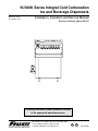
VU300K Series Integral Cold Carbonation
Ice and Beverage Dispensers
Order parts online
www.follettice.com
Installation, Operation and Service Manual
Service numbers above 50000
Following installation, please forward this manual
to the appropriate operations person.
801 Church Lane • PO Box D, Easton, PA 18044, USA
Toll free (800) 523-9361 • (610) 252-7301
Fax (610) 250-0696 • www.follettice.com
U® L
C
U® L
00119628R01
2
Table of contents
Welcome to Follett Corporation
Important cautions
Specifications
Installation
Installing dispenser in counter
Field wiring diagrams
Connecting beverage lines
Installing optional icemaker
Operation
How the dispenser works
Cleaning
Service
Dispense chute cover removal
Auger motor assembly removal
Gate assembly removal
Auger and auger tube removal
Dispenser wheel removal
Wiring diagrams
Troubleshooting
Replacement parts
4
4
5
8
8
9
9
10
11
11
12
14
14
14
14
14
14
15
17
19
Follett Corporation
Equipment Return Policy
Follett equipment may be returned for credit under the following conditions:
1. The equipment is new and unused.
2. A return authorization number has been issued by customer service.
3. Follett receives the equipment at the factory in Easton, PA within 30 days of the issue of the return authorization number.
4. The equipment must be returned in Follett packaging. If the packaging has been damaged or discarded, Follett will forward, at the customer’s
expense, new packaging.
Note:
Return freight charges are the responsibility of the customer. If equipment is returned and is damaged because of improper packaging,
Follett Corporation will not be held responsible.
Credit will be issued when:
The equipment has been inspected by Follett and deemed suitable to be returned to stock.
Note:
A 15% restocking charge will be deducted from the credit. If the cost to return the product to stock exceeds 15%, the actual cost
will be deducted.
3
Welcome to Follett
Follett ice dispensers enjoy a well-deserved reputation for excellent performance, long-term reliability and
outstanding after-the-sale support. To ensure that this dispenser delivers that same degree of service, we ask
that you take a moment to review this manual before beginning the installation of the dispenser. Should you have
any questions or require technical help at any point, please call our technical service group, (800) 523-9361 or
(610) 252-7301.
Before you begin
After uncrating and removing all packing material, inspect the equipment for concealed shipping damage. If
damage is found, notify the shipper immediately and contact Follett Corporation so that we can help in the filing of
a claim, if necessary.
Check your paperwork to determine which model you have. Follett model numbers are designed to provide
information about the type and capacity of Follett ice dispensing equipment. Following is an explanation of the
different model numbers in the VU300 series.
VU300K8LP
Ice and valve actuation
Tower side (facing unit)
L – Left hand side
R – Right hand side
P – Pushbutton
L – Lever
Number of valves
8 or 10
Beverage cooling
Model series
!
K – Integral beverage cooling with cold carbonation
Important cautions
Storage area of dispenser contains mechanical, moving parts. Keep hands and arms clear of
this area at all times. If access to this area is required, power to unit must be
disconnected first.
Ice is slippery. Maintain counters and floors around dispenser in a clean and ice-free condition.
Ice is food. Follow recommended cleaning instructions to maintain cleanliness of delivered ice.
Always disconnect power before cleaning or servicing the dispenser.
Failure to remove all sanitizer may result in health hazard.
Follett manual load dispensers can accommodate most cube/cubelet ices up to 1" (26mm) square, or
Follett compressed nugget ice. Crushed, flake, bagged, nugget or congealed ice cannot be used. Use
of these ices can jam dispenser and void warranty. Separate any “waffle-like” sections of cubes
before adding to dispenser. For ice compatibility questions, please call Follett customer service at
(800) 523-9361 or (610) 252-7301.
4
Specifications
Electrical
Each dispenser requires a separate circuit with electrical disconnect within 10 ft (6m). Equipment ground
required. Standard electrical – 115V, 60Hz, 1 phase. Maximum dispenser fuse – 20 amps, Maximum icemaker
fuse – 20 amps each. Cord and plug provided with each dispenser.
VU300K series
Icemaker
amperage
Dispenser
amperage
11.0 amps ea (2)
11.5 amps
Plumbing
Dispenser
3/4" PVC pipe nipple for bin drain
3/4" PVC pipe nipple for drain pan drain
1" ID hose for beverage bath drain
Beverage connections
1/4" ID syrup beverage hose
3/8" 45° flair fitting for carbonated water inlet
1/4" ID CO
2
3/8" ID plain water inlet
Note:
Set CO pressure to 75 psi and syrup pressure to 60 psi.
2
Drains should be hard piped and insulated. Maintain at least 1/4" per foot (6mm per 304mm run)
slope on drain line run.
Water disconnect within 10 feet (3m) of dispenser is suggested for automatic load units.
Follett recommends use of a Follett model AFSYSTMFL4S water filter on icemakers connected
to automatic fill dispensers.
Icemaker
Refer to detailed specifications in icemaker installation manual
packed with icemaker
5
Dimensions and clearances
VU300 series
Required clearances
60" (1524mm) minimum above counter for installation if dispenser will be dropped into counter
49" (1245mm) minimum above counter for auger removal
12" (305mm) minimum on ice chute side for service
12" (305mm) minimum on side opposite ice chute if ice transport tube enters this side
12" (305mm) minimum between dispenser side(s) and optional icemaker(s)
Front View
40.875"
(1039mm)
(shown with two Chewblet FC400A
auto-fill icemaker kits)
25.25"
(642mm)
entrance for
beverage line
54.875
(1394mm)
18.875"
(480mm)
carbonator
pump
29.625"
(753mm)
17"
(432mm)
electric
conn.
disp.
drains
6"
(153mm)
12"
(305mm)
manual load unit
dispenser with 1 optional auto-fill icemaker kit(s)
dispenser with 2 optional auto-fill icemaker kit(s)
Side View
32.375"
(823mm)
24.62"
(626mm)
beverage
lines enter
through
bottom
ice
transport
tube entry
1"
(26mm)
drains
bin signal
power
7" (178mm)
3" (77mm)
10"
(254mm)
2.5"
(64mm)
27.5"
(699mm)
3/4"
(19mm)
drain
9"
(229mm)
9"
(229mm)
15"
(381mm)
30"
(762mm)
6
8.5"
(216mm)
2"
(51mm)
Installation
Installing dispenser in counter
Note:
All dispensers must be supported from below with supplied 4" – 6" (102 – 153mm) adjustable leg accessory,
or equivalent. Do not hang dispenser on flange.
All dispensers must be installed level in both directions to ensure proper operation.
1. Check that dispenser location meets all requirements in this manual and cut counter as shown.
Plan View
Single-sided dispensers
counter cutout
Shaded area is additional cut-out required for
slide-in installations only
Min.
30.375" 33"
(772mm) (839mm)
flat
surface
38.5"
(978mm)
front of counter
2. Place support blocks in cabinet to raise dispenser to a height of 12" (305mm).
3. Place dispenser in counter onto support blocks.
4. Attach adjustable legs to dispenser.
5. Remove support blocks and lower dispenser feet to floor.
6. Adjust legs for 1/8" (4mm) clearance between dispenser lip and countertop to verify there is no load on flange.
7. Apply a bead approximately 1/4" (6mm) in diameter of NSF-listed silicone sealant (Dow Corning RTV-732 or
equivalent) around perimeter of dispenser where it meets counter. Smooth sealant to a 1/8" (4mm) radius.
8. Install a PVC drain line with at least a 1/4" per foot (20mm per 1m) slope. Insulate drain line to prevent
condensation.
Note:
Do not apply excessive heat if any sweating of fittings is necessary. Heat conduction through metal may
melt threads in plastic drain.
Do not reduce drain line size or tie drains together.
9. Install carbonator pump. See instruction enclosed with pump for detailed installation instructions.
10. Make electrical connections in accordance with applicable wiring diagrams provided. Provide disconnects within
10 ft (3m) of dispenser and icemaker for servicing.
7
Field wiring diagrams
Note:
Field wiring diagrams are intended to aid electricians or technicians in understanding how equipment
works. All field wiring must be installed in accordance with all local and NEC codes.
If attaching
optional icemaker
accessory
ICEMAKER #1
(OPTIONAL)
LOWER JUNCTION BOX
DISPENSER
Electric
Power
Source
LEFT JUNCTION BOX
W
B
GND
GRN
ELECTRIC
POWER
SOURCE UPPER JUNCTION BOX
W
B
B
W
RIGHT JUNCTION BOX
GRN
GND X
BL
Y
ICEMAKER #2
(OPTIONAL)
RD
LOWER JUNCTION BOX
LEGEND
X
B
W
WIRENUT FIELD
CONNECTIONS
EQUIPMENT
GROUND
BLACK
WHITE
GRN
GREEN
BL
Y
RD
BLUE
YELLOW
RED
ELECTRIC
POWER
SOURCE UPPER JUNCTION BOX
W
W
B
B
GRN
GND X
Connecting beverage lines
1. Connect syrup and water lines. Non-carbonated water line will be labeled “water”. Syrup lines are numbered
and correspond to the valves as shown in drawing(s) below. Valve one is always next to ice tower.
2. The center 4 valves are pre-plumbed to both carbonated and non-carbonated water lines with the
QuickCARB™ beverage manifold. Valves can be individually changed from carbonated to non-carbonated
flavor with the flip of a lever (see below).
3. Clean and sanitize beverage lines in accordance with cleaning instructions.
VU300B QuickCARB manifold
(see dispenser for model specific
QuickCARB configuration)
10 9 8 7 6 5
4 3
2 1
Rear View
carbonated
Valve position #1 is always next to ice
tower. Left hand unit shown.
non-carbonated
8
Installing optional auto-fill icemaker kit(s)
Correct installation of remote icemaker(s) is critical to proper performance of icemaker. Refer to installation
manual packed with icemaker for important details on ice transport tube run, ventilation requirements and other
installation requirements. Failure to comply with instructions may void warranty.
To start and operate dispenser
1. Follow detailed cleaning instructions in service manual before operating dispenser.
2. Slowly pour water into ice water bath area to fill empty bath and submerge coils. Coils are submerged when
water starts to flow out overflow drain. DO NOT SPLASH WATER ON ELECTRICAL BOX. Once filled with
water, add ice to bath until ice covers top of waterbath.
3. For manual load units, remove front drain pan or rear lid and fill storage area with approved ice.
Note: Follett manual load dispensers can accommodate most cube/cubelet ices up to 1" (26mm) square, or
Follett compressed nugget ice. Crushed, flake, bagged, nugget or congealed ice cannot be used. Use of
these ices can jam dispenser and void warranty. Separate any “waffle-like” sections of cubes before
adding to dispenser. For ice compatibility questions, please call Follett customer service at
(800) 523-9361or (610) 252-7301.
4. Turn power switch located on dispenser control box to ON position.
5. For automatic fill units, follow detailed instructions in icemaker installation section of installation manual, then
turn icemaker (bin signal) switch(es) located on dispenser control box to ON position and begin to make ice.
6. When dispenser has at least 6" (153mm) of ice in storage area, test operation.
9
Operation
How the dispenser works
Follett’s dispensers may be fed by Follett remote icemakers or manually loaded (using ice from another source).
In all models, ice is stored below the counter in the dispenser storage area. When the dispense lever or button is
pushed, the dispense motors are activated. This causes the wheel assembly in the storage area to turn, moving
ice to the vertical auger assembly, which carries ice up to the dispense chute where it drops by gravity into the
container.
In units used with an optional icemaker accessory, ice is manufactured remotely and may be located up to 20 ft
(6m) away from the dispenser. Extruded ice is transported through a tube and pushed to the storage
compartment of the dispenser. When the bin is filled, a bin thermostat shuts the icemaker off to avoid overfilling
the bin. The icemaker will restart after 20 minutes if the bin is calling for ice.
Units with integral ice water bath beverage cooling are equipped with a waterbath timer circuit that activates the
water bath pump for 35 minutes when ice lever or button is activated, or when the ice water bath warms up and
calls for more ice.
Ice movement
10
Cleaning
Using solutions below, clean and sanitize storage area and beverage lines before starting unit and on a routine
basis as noted below.
Note: Always disconnect power before cleaning dispenser.
Do not run plastic parts through a dishwasher.
Solution A:
Combine 1 oz (250ml) bleach with 2 gal (8L) hot water or use Ecolab Mikro-chlor Cleaner
per manufacturers instructions.
Solution B:
Combine 1/4 oz (50ml) bleach with 2 gal (8L) hot water or use Ecolab Mikro-chlor Cleaner
per manufacturers instructions.
Note:
Cleaning solutions temperature must be at 75˚ – 125˚F (24˚ to 52˚C)
Recommended cleaning prior to start up
Cleaning ice storage area before use
1. Refer to disassembly instructions (see Service section) and remove dispense wheel from ice storage area.
2. Remove auger, auger tube and dispense mechanism.
3. Wipe all components and ice storage area with cleaning Solution A.
4. Rinse all components and ice storage area thoroughly with clear, potable water.
5. Wipe all components and ice storage area with sanitizing Solution B.
Cleaning beverage lines
Prepare 6 gallons (23L) of cleaning Solution A. Fill a clean product tank with cleaning solution. Fill a second
clean product tank with potable rinse water.
1. Disconnect all syrup lines from product containers.
2. Connect syrup line #1 to cleaning solution tank, pressurize tank to 20-50 psi, and dispense 1/2
gallon (2L) of solution into a suitable container from valve #1.
3. Connect syrup line #1 to rinse tank, pressurize tank to 20-50 psi, and dispense 3 gallons (11L)
into a suitable container from valve #1.
4. Repeat this cleaning and rinsing for all syrup lines.
5. Remove diffusers and nozzles from valves, soak in cleaning solution, rinse well and reinstall.
Sanitizing beverage lines
Prepare 6 gallons (23L) of sanitizing Solution B. Fill a clean product tank with this solution.
1. Connect one tank to syrup line #1. Dispense 1/2 gallon (2L) from valve #1.
2. Repeat for all remaining syrup lines, allowing sanitizing solution to remain in all circuit lines for
15 minutes.
3. Connect a clean, empty tank (pressurized to 50 psi) to each syrup line and blow out sanitizer by
operating each valve.
4. Remove diffusers and nozzles from valves, soak in sanitizing solution for 15 minutes, rinse well and
reinstall.
5. Reconnect all lines and dispense product through valves to purge any remaining sanitizer.
11
Recommended daily dispenser cleaning
1. Remove all debris from drain pan.
2. Pour 1 gallon (4L) hot water into drain pan to keep drain lines clear.
Recommended weekly dispenser cleaning
1. Remove drain pan and grille and wash with Solution A. Rinse thoroughly.
2. Remove nozzles and diffusers from valves, soak for at least 10 minutes in cleaning Solution A, rinse,
sanitize with Solution B and reinstall.
3. Pour a solution of one cup (8oz/237ml) household bleach mixed with one gallon (3.8L) hot water into
drain pan to help prevent algae growth in drain lines.
Recommended quarterly dispenser cleaning
1. Remove top from dispenser and turn power switch to OFF position.
2. Remove ice from storage area.
3. Remove dispense chute cover, chute, auger motor assembly, auger and auger tube (see Service section).
4. Remove drain pan, grille, dispense wheel, agitator rods, and drive shaft (see Service section).
5. Clean all components and bin storage area with Solution A, rinse thoroughly with clear water and sanitize
with Solution B.
6. Remove nozzles and diffusers from valves, soak for at least 10 minutes in cleaning Solution A, rinse,
sanitize with Solution B and reinstall.
7. Remove side access panel next to ice tower with two upper screws and lift out.
8. Disengage service drain tube (on utility connection side of dispenser) from mounting bracket and drain
ice water bath.
9. Use a bottle brush to clean coils with Solution A, rinse and sanitize with Solution B.
10. Reposition ice water bath drain line in up position so water does not drain out.
11. Pour Solution A into ice water bath until it flows out overflow drain.
12. Turn power ON to unit and dispense a small cup of ice to activate pump.
13. Allow pump to run for two minutes to clean pump and pump lines.
14. Turn power OFF.
15. Drain bath and replace drain tube in mounting bracket in up position to avoid siphoning water bath water.
Putting unit back in service after quarterly cleaning
1. Fill ice water bath with water until water spills out of bath overflow drain.
2. Reassemble components.
3. For manual load units, fill unit with an approved ice (see important cautions on page 4).
4. For automatic load units with R400A/W (R404A refrigerant) icemakers, turn bin signal switch(es) and
dispenser power switch to ON position and allow storage area to fill.
5. Push dispense button or lever to test that dispenser is functioning properly.
Recommended quarterly cleaning of optional auto-fill icemaker kit(s).
Units equipped with optional icemakers require cleaning of icemaker system at least every six months, and more
often if local water conditions dictate. Failure to clean icemaker system will result in decreased performance and
potential damage to icemaker. Refer to Icemaker Installation, Operation and Service Manual.
12
Service
Dispense chute assembly
Dispense chute cover removal
quick release pins
1. Remove top cover.
2. Remove two screws from top cover and pull cover forward and
down to remove.
3. On push button units, disconnect plug on harness.
Auger motor assembly removal
1. Remove drain pan.
2. Remove thumbscrews from splash guard and remove.
3. Remove thumbscrews from splash panel; lift and pull forward
at base of panel and remove.
4. Unplug auger motor at connector.
5. Remove two 1/4-20 bolts holding auger motor to hold-down
bracket.
6. Remove two thumbscrews from auger motor stabilizer bracket
and set aside.
7. Lift auger motor off.
gate
assembly
ice chute
gate assembly
springs
mounting
bracket
ice chute
Dispenser cutaway – Front View
auger motor
Gate assembly removal
1. Remove dispense chute cover and auger motor assembly.
2. Remove thumbscrews on each side of clear focus chute and
remove.
3. Remove quick release pin holding dispense gate assembly
and chute.
4. Lift gate up and over hinge tabs, then carefully pull and tilt to
unhook from solenoid link.
5. Pull ice chute toward you to unclip from dimples on chute
mounting bracket.
6. Pull ice chute and gate toward you and out through panel
opening.
7. Lift dispenser mechanism assembly off auger and auger tube.
auger tube
wheel motor
auger
tube
ring
auger
drive
shaft
Auger and auger tube removal
1. Remove dispense chute cover and auger-motor assembly.
2. Remove side panel of tower.
3. Remove screw holding top auger tube ring to lower ring.
4. Lift auger out of auger tube.
5. Lift out auger tube, turning as needed to clear rivnuts on side
auger motor mounting bracket.
Front View
Dispenser wheel removal
1. Remove dispenser top and turn power switch OFF.
2. Remove all ice from bin.
3. Remove drain pan and ice bin access cover below it.
4. Remove splash guard and wheel motor access cover.
5. Unplug wheel motor at connector and remove ground wire.
5. Remove wheel motor by
pulling out two quick release pins.
6. Lift drive shaft up through hole in countertop.
7. Lift dispense wheel out through drain pan opening.
13
fixed ramped
yoke rod with
bracket (below
rotating drive
bar)
fixed yoke
rod with
bracket
Wiring diagram
VU300K series
L2
AUGER MOTOR
DISPENSE
PL1-1
GRAY
C
C
NO
TOP LID
SWITCH
R1
PURPLE
4
NO
DRAIN
PAN
SWITCH
LID
POWER
POWER
SWITCH
PL1-2
ORANGE
PL2-1
PURPLE
BLK
7
MTR
BLACK
PL3-2
RED
RED
PURPLE
WHT
PL3-3
WHT
M2
WHT
WHITE
L2
MTR
ORANGE
BLACK
PL2-2
BLUE
M1
WHEEL MOTOR
READY
BLACK
L2
L1
BATHPUMP
MOTOR
READY
PL5-1
GRAY
LID
PUMP
BATH CONTROL
BOARD
PL5-2
M3
BLK
(35 MIN ON DELAY)
GREEN
RED
BLACK
WHITE
GRAY
L1
CARB.
TANK
LOW HIGH COMMON
CARB.
PUMP
CONTROL
COM
L2
CARB.
PUMP
NO
115 VOLTS
T1
DISPENSE
SWITCH
PL6-1
RED
YELLOW
24 VOLTS
PL6-3
BROWN
NO
C
24V YEL
24V RED
RED
DISPENSE RELAY
R1
BROWN
B
YELLOW
A
BATH CONTROL BOARD
RED
24VAC RED
BATH
SOLENOID
BATH SOL
C
RED
BATH SOL
STATUS LIGHTS
TEMP
SENSOR
YELLOW
24VAC YEL
BLUE
NO
PL4-2
PL4-1
YELLOW
GREEN - COLD
(12 SEC ON: 1 MIN OFF)
NC
RED - WARM
T
DISPENSE
SOLENOID
DISPENSE
R1
RED
PL4-4
PL4-3
BROWN
6
YELLOW
9
PL6-2
RED
PL6-4
BLUE
BIN T'STAT
T-STAT
2
1
RED
IM_#1
BLUE
BLUE
AUTOFILL
PL1-3
RED
IM_#2
BIN SIGNAL (24V)
ICEMAKER #1
YELLOW
BIN SIGNAL (24V)
ICEMAKER #2
24V JUNCTION BOX
PL1-4
C
NO
DRAINPAN
SWITCH
BLACK
YELLOW
BEV HARN
BLUE
SWITCH
BROWN
Valve_1
PL7-1
Valve_2
Valve_3
Valve_4
Valve_5
BLACK
BLACK
LEGEND:
TERMINAL STRIP CONNECTION
BROWN
KEYSWITCH
Valve_6
Valve_7
Valve_8
Valve_9
Valve_10
PL7-2
14
PIN and SOCKET CONNECTION
Dispenser troubleshooting guide
Before calling for service
1. Check that ice is in the dispenser and that congealed cubes are not causing a jam.
2. Check that circuit breaker and switches are in ON position.
3. Check that drain pan and top are on securely. If ajar, dispenser will not operate. When the top is off, auger
does not operate, even though the solenoids do (page 18).
4. Check that all drains are clear.
Note: For units equipped with Follett Chewblet auto-fill icemaker kit(s), see Icemaker Operation and Service
Manual for service and troubleshooting information.
Symptom
Possible cause
Solution
Ice does not dispense.
• Auger motor does not run
• Wheel motor does not run
1. Power switch faulty or in OFF
position; loose connection.
2. Faulty dispense switch.
3. Faulty transformer.
4. Drain pan ajar.
5. Faulty drain pan safety switch.
1. Turn power switch to ON position;
check connections.
2. Replace switch.
3. Replace transformer.
4. Check pan and reseat.
5. Replace switch.
Ice does not dispense.
• Auger motor runs
• Wheel motor runs
• Gate does not open
1. Loose electrical connection.
2. Linkage problem between
solenoid and gate.
3. Faulty solenoid.
1. Check connections.
2. Check linkage.
Ice does not dispense.
• Auger motor does not run
• Wheel motor runs
1. Loose electrical connection.
2. Faulty auger motor.
3. Faulty run capacitor.
1. Check connections.
2. Check auger motor.
3. Check run capacitor.
Ice does not dispense.
• Auger motor runs
• Wheel motor does not run
1. Loose electrical connection.
2. Faulty wheel motor.
3. Faulty run capacitor.
1. Check connections.
2. Check wheel motor.
3. Check capacitor.
Warm drinks or soda foaming.
1. No ice in storage bin.
2. Water drained out of ice water
bath.
1. Fill storage area with ice or check
icemaker operation.
2. Check that ice water bath drain
tube is in fixed upright position.
3. Check pump and PC board for
output.
4. Cycle power on/off to reset board.
5. Set CO2 pressure to 75 psi.
3. Circulating pump not running.
4. Board off on fill error.
5. CO2 pressure is set too high.
No ice in dispenser.
1. Power switch in OFF position or
faulty.
2. Bin signal switches in OFF
position or faulty.
3. Faulty bin thermostat.
4. Faulty transformer.
5. Icemaker related problem.
6. Faulty or disconnected wiring.
15
3. Replace solenoid.
1. Check switch and replace if
necessary.
2. Check switch and replace if
necessary.
3. Replace bin thermostat.
4. Replace transformer.
5. Refer to Icemaker Operation and
Service Manual for diagnosing.
6. Check for power and bin signal on
icemaker PC board.
Symptom
Carbonator pump not turning on.
Possible cause
1. Loose connection.
2. Electrode connections on
carbonator tank are satisfied.
3. Carbonator pump or level
control board is defective.
Solution
1. Check carbonator pump power at
plug and at level control board.
2a. Check connection between low
level electrode and level control
board.
2b. Check ground wire on carbonator
tank.
3. Replace pump/control board.
Carbonator pump is not turning off.
1. Loose connection.
Carbonation system is not
carbonating.
1. Loose connection.
1. Check all CO2 and water
2. CO2 pressure.
connections.
2. Set CO2 pressure to 75 psi.
3. Water pressure is too high.
4. Carbonator pump is defective.
Carbonation system is producing
1. CO2 pressure is set too high.
excessively carbonated beverages. 2. Drinks may be warm.
1a. Check connection between high
level electrode and level control
board.
1b. Replace electrodes/control board.
3. Lower water pressure to
approximately 50 psi.
4. Replace pump.
1. Set CO2 pressure to 75 psi.
2. See “warm drinks” symptom.
If problems persist after following this basic troubleshooting guide, call Follett’s technical
service department at (800) 523-9361 or (610) 252-7301.
16
Operational Status
The chart below shows the operational status of various parts when certain switches are turned off or accessories
are removed.
Condition
Pump
Solenoids
Auger
Wheel
Beverage
valves
Top lid off
OFF
ON
OFF
OFF
ON
Drain pan off
ON
ON
OFF
OFF
OFF
On/off switch
in OFF position
OFF
OFF
OFF
OFF
OFF
Beverage
switch in OFF
position
ON
ON
ON
ON
OFF
Waterbath circuit board operation
The temperature sensor is hard wired directly to the circuit board. The waterbath circuit board operates on 24
volts AC. The bath pump will run for 35 minutes whenever ice is dispensed or the bath calls for ice.
Optimal beverage temperature is controlled by the circuit board located in the electrical box. The board monitors
the waterbath temperature and holds it to a factory setting. When the Red LED is ON, the bath solenoid, auger
motor, wheel motor and bath pump are energized. Ice will be dispensed into the waterbath for 12 seconds, then
stop for 60 seconds. The pump will stay energized, and the circuit board will then monitor the water
temperature. If it is below the set point, the Green LED will come on, the Red LED light will go off, and ice will
not dispense into the waterbath. If the temperature of the bath is determined to be above the set point, the Red
LED will remain on. The circuit board has a delay of 60 seconds before more ice is dispensed into the
waterbath.
LED indicators:
Green – the waterbath is at the set temperature.
Red – the bath temperature is above the set temperature and the bath is calling for ice.
Flashing LED indicators:
Flashing Red and Green – the circuit board has gone into an error mode:
Alternate flashing – circuit board has power and is waiting for hopper cover and dispenser top to be
replaced.
Simultaneous flashing – the waterbath did not reach set temperature in 40 minutes. Reset this error
mode by turning power off, removing top lid, drain pan or rear lid.
Electrical box
Front View
beverage bath
indicator
0
I
0
I
0
I
#1 #2
warm/red LED
power on/off
switch
probe
icemaker
switches
17
cold/green LED
Replacement parts
Plan View
Single-sided Dispenser
1
2
3
1
6
5
8
7
6
4
Reference #
1
2
3
Not shown
Not shown
4
Not shown
5
6
Not shown
7
8
Not shown
Not shown
Not shown
Not shown
Not shown
Not shown
Not shown
Not shown
Not shown
Not shown
Not shown
Not shown
Description
Lid, with graphics, single-sided
Graphics, “Follett”
Access panel, tower, single-sided
Cover, ice opening (below drain pan)
Drain pan assembly and grille
Drain pan, plastic
Switch, drain pan safety
Grille, drain pan
Chute cover, dispense, push-button with switch
Chute cover, dispense, lever
Splash guard
Thumbscrew, 10/32-1/2, splash guard
Switch, dispense, PB
Switch, dispense lever (includes boot and spacer)
Boot, dispense switch button, lever
Access cover, wheel motor (behind splash guard)
Fitting, drain, drain pan
Lip kit (plastic strip bordering ice bin opening and adhesive)
Insulation, transport tube (sold by the foot)
Tube, ice transport, 10 ft
Tube, ice transport, 20 ft
Plug 2 lead, male
Plug 2 lead, female
Brackets, drain pan locator
18
Part #
00126805
00116780
00108407
00143685
00126862
00108829
502475
00108845
502440
502439
00121517
501100
502441
501714
501841
00114546
00143677
502285
501176
502522
502523
502333
502334
00143693
1
4
2
3
4
15
8
Top View
lower ring
Top View
auger tube seal
16
reinforcing
tab
9
17
5
19
16
6
10
11
7
18
Front View
auger tube
14
13
Reference #
1
2
Not shown
Not shown
3
4
5
6
7
8
9
Not shown
Not shown
Not shown
10
11
12
13
Not shown
Not shown
Not shown
Not shown
14
15
16
17
18
19
Not shown
Not shown
countertop
section
12
Description
Motor, auger (includes capacitor)
Bracket, auger motor hold-down
Bracket, auger motor stabilizer
Seal, shaft, auger motor
Auger
Auger tube (includes insulation)
Insulation, auger tube
Ring, auger tube, upper
Ring, auger tube, lower
Motor, wheel, Brother (includes capacitor)
Bracket, wheel motor
Capacitor, wheel motor, Brother
Gasket, wheel motor bracket
Pin, quick release, wheel motor (2 required)
Drive shaft assembly, for Brother motor
Agitator rods, fixed, front and back
Wheel, dispense
Bearing plate, bottom auger
Bearing, bottom, auger
Agitator rod, ramped
Bracket, fixed agitator (3 used per unit)
Thumbscrew, 10/32 x 3/4, fixed agitator bracket (2 required)
Tee, drain
Thermostat
Bracket, ice hose and wheel motor
Union, 3/8" (includes 00107433)
Shelf, carbonator pump
Pump, carbonator (includes 00106658, 00109355)
Mounting screws & fittings, carbonator pump
Leg
19
Part #
00115212
502047
00108498
501977
501980
00126870
502099
501939
502155
502657
501981
502658
501982
206283
00126888
502629
501978
501971
501972
502628
501974
501259
502059
500514
502050
00107516
00106658
00107524
00109355
00137257
VU300 dispense assembly
Side View
1
VU300 dispense assembly
Top View
2
3
1
3
7
4
6
Reference #
1
2
3
4
5
Not shown
6
7
Not shown
Not shown
4
Description
Gate, dispense
Linkage pin, gate/solenoid
Pin, quick release, 3" (77mm), gate and lever
Chute, ice
Solenoid
Boot, solenoid
Dispense mechanism assembly
Spring, dispense mechanism (1 per side)
Chute, focus
Lever, dispense
20
5
Part #
501955
502096
501949
501952
501961
502098
501948
501950
502459
501953
3
24
12
24
23
1
15
14
2
15
18
20 19
21
16
17
13
11
10
9
5
5
16
7
4
Reference #
1
2
Not shown
3
4
5
Not shown
6
7
8
9
10
11
Not shown
12
13
14
15
16
17
18
19
20
21
22
23
24
Description
Pump, waterbath (includes mounting plate and elbow)
Elbow, overflow 1" (26mm) x 3/4 MPT
Elbow, clean out, drain, 3/8" (10mm) x 3/8 MPT
Syrup coil
QuickCARB foam pack assembly
Foam pack assembly, 10 valve
Foam pack assembly, 8 valve
Coil, carbonated water, 8 valve and 10 valve
Coil, carbonated, outer
Coil, non barb, inner
Manifold, carbonated water, 8 valve and 10 valve
Manifold, water 8 valve and 10 valve
Guide, ice bath, LH
Guide, ice bath, RH
Tubing, vinyl, pump (order by foot, 3ft minimum)
Water probe, high level (red)
Water probe, low level (black)
Elbow, 3/8" swivel (includes 00107433, 0107490
Washer, seal, 3/8" (black)
Check valve, 3/8" (includes 00107433)
Elbow, 1/4" swivel (includes 00107466, 00106914)
Washer, seal, 1/4" (white)
Check valve, 1/4" (includes 00107466
Pressure relief valve
Carbonator tank
Clamp, pump hose
Bracket, carbonation tank
21
6
22
8
Part #
00111476
502465
502466
00125864
00127043
00127068
00127076
00119560
00119578
00119552
00207540
00123141
00127084
00127092
501966
00107409
00107417
00107425
00107433
00107532
00107458
00107466
00107540
00107482
00107508
500378
00106625
24VAC (YEL)
NC
24VAC (RED)
C
NO
2
LID
3
PUMP
1
3
L2 (WHT)
Top View
MTR
ready
(orange)
5
Beverage bath
control board detail
4
Front View
Side View
LOW
HIGH
COM
7
N.O.
COM
0
I
0
I
0
I
N.O.
BEV. BATH
INDICATOR
N.C.
COM
INPUT VOLTAGE
WARM COLD
Cold carbonation level
control board detail
4
8
4
6
5
Reference #
1
2
3
4
5
6
7
Not shown
Not shown
Not shown
Not shown
Not shown
Not shown
8
Description
Transformer, 24V
Relay, dispense
Strips, terminal
Switches (power and icemaker)
Board, circuit and probe (one unit)
Bracket, probe
Switch, safety
Switch, safety, drain pan assembly, LH unit
Switch, safety, drain pan assembly, RH unit
Switch, dispense, lever
Bracket, safety switch, drain pan, RH
Bracket, safety switch, drain pan, LH
Thermostat, bin level
Control board, cold carbonation
22
Part #
502058
501826
502472
502209
502473
00111484
502511
502500
502501
502505
502609
502610
500514
00106708
23
801 Church Lane • PO Box D, Easton, PA 18044, USA
Toll free (800) 523-9361 • (610) 252-7301
Fax (610) 250-0696 • www.follettice.com
U® L
C
U® L
00119628R01
02/06