1
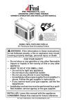
B-VENT DECORATIVE GAS FIREPLACE
OWNER’S OPERATION AND INSTALLATION MANUAL
PFS
®
US
models P324E, VP324E, P325E(B) AND VP325E(B)
Natural Gas
WARNING: If the information in these instructions
is not followed exactly, a fire or explosion may result
causing property damage, personal injury or death.
FOR YOUR SAFETY
— Do not store or use gasoline or any other flammable
vapors or liquids in the vicinity of this or any other
appliance.
— WHAT TO DO IF YOU SMELL GAS :
• Do not try to light any appliance.
• Do not touch any electrical switch;
• Do not use any phone in your building.
• Immediately call your gas supplier from a neighbor’s
phone. Follow the gas supplier’s instructions.
• If you cannot reach your gas supplier, call the fire
department.
— Installation and service must be performed by a qualified installer, service agency or the gas supplier.
INSTALLER: Leave this manual with the appliance.
CONSUMER: Retain this manual for future reference.
For more information, visit www.fmiproducts.com
WARNING: Improper installation, adjustment, alteration, service or maintenance can cause injury or
property damage. Refer to this manual for correct installation and operational procedures. For assistance
or additional information consult a qualified installer,
service agency or the gas supplier.
NOT FOR USE WITH SOLID FUEL
CHECK LOCAL CODES PRIOR TO INSTALLATION
SAVE THIS BOOK
This book is valuable. In addition to instructing you on
how to install and maintain your appliance, it also contains information that will enable you to obtain replacement parts or optional accessory items when needed.
Keep it with your other important papers.
This appliance may be installed in an aftermarket*, permanently located, manufactured (mobile) home, where
not prohibited by state or local codes.
This appliance is only for use with the type of gas indicated on the rating plate.
This appliance is not convertible for use with other
gases, unless a certified kit is used.
*Aftermarket: Completion of sale, not for purpose of resale, from the manufacturer.
TABLE OF CONTENTS
Safety................................................................... 3
Unpacking............................................................ 4
Introduction........................................................... 4
Selecting Location................................................ 5
Product Specifications.......................................... 6
Pre-Installation Preparation.................................. 7
Venting Installation............................................... 8
Fireplace Installation...........................................11
Operation............................................................ 18
Inspecting Burners ............................................ 19
2
Cleaning and Maintenance................................. 20
Replacement Parts............................................. 20
Service Hints...................................................... 20
Technical Service............................................... 20
Wiring Diagram................................................... 21
Troubleshooting.................................................. 22
Accessories........................................................ 25
Parts................................................................... 26
Warranty...............................................Back Cover
www.fmiproducts.com
108794-01G
Safety
WARNING: This product contains and/or generates chemicals
known to the State of California
to cause cancer or birth defects
or other reproductive harm.
IMPORTANT: Read this owner’s
manual carefully and completely
before trying to assemble, operate or service this fireplace.
Improper use of this fireplace
can cause serious injury or death
from burns, fire, explosions,
electrical shock and carbon
monoxide poisoning.
DANGER: Carbon monoxide
poisoning may lead to death!
This fireplace is a vented product. This fireplace
will not produce any gas leakage into your home
if properly installed. This fireplace must be
properly installed by a qualified service person.
If this unit is not properly installed by a qualified
service person, gas leakage can occur.
Carbon Monoxide Poisoning: Early signs of
carbon monoxide poisoning resemble the flu,
with headaches, dizziness or nausea. If you
have these signs, the fireplace may not have
been installed properly. Get fresh air at once!
Have fireplace inspected and serviced by a
qualified service person. Some people are more
affected by carbon monoxide than others. These
include pregnant women, people with heart or
lung disease or anemia, those under the influence of alcohol and those at high altitudes.
Propane/LP gas and natural gas are both
odorless. An odor-making agent is added
to each of these gases. The odor helps you
detect a gas leak. However, the odor added
to these gases can fade. Gas may be present
even though no odor exists.
Make certain you read and understand all
warnings. Keep this manual for reference. It
is your guide to safe and proper operation of
this fireplace.
WARNING: Any change to
this fireplace or its controls can
be dangerous.
108794-01G
1. This appliance is only for use with the
type of gas indicated on the rating plate.
This appliance is not convertible for use
with other gases unless a certified kit is
used.
2. For propane/LP fireplace, do not place
propane/LP supply tank(s) inside any
structure. Locate propane/LP supply
tank(s) outdoors. To prevent performance
problems, do not use propane/LP fuel tank
of less than 100 lbs. capacity.
3. If you smell gas
•shut off gas supply
•do not try to light any appliance
•do not touch any electrical switch; do not
use any phone in your building
•immediately call your gas supplier from
a neighbor’s phone. Follow the gas supplier's instructions
•if you cannot reach you gas supplier, call
the fire department.
4. Never install the fireplace
•in a recreational vehicle
•where curtains, furniture, clothing or
other flammable objects are less than
36" from the front and 42" from the top
top of the fireplace. For side clearances
see Figure 6, page 7
•in high traffic areas
•in windy or drafty areas
5. This fireplace reaches high temperatures.
Keep children and adults away from hot
surfaces to avoid burns or clothing ignition. Fireplace will remain hot for a time
after shutdown. Allow surfaces to cool
before touching.
6. Carefully supervise young children when
they are in the room with fireplace.
7. A hearth extension is not required with this
appliance. If one is installed, it is for aesthetic purposes only and does not have
to meet the standard requirements.
8. Turn fireplace off and let cool before servicing or repairing. Only a qualified service
person should install, service or repair
this fireplace. Have fireplace inspected
annually by a qualified service person.
9. You must keep control compartments,
burners and circulating air passages
clean. More frequent cleaning may be
needed due to excessive lint and dust
from carpeting, bedding material, etc.
Turn off the gas valve and pilot light before
cleaning fireplace.
10.Have venting system inspected annually by
a qualified service person. If needed, have
venting system cleaned or repaired. See
Cleaning and Maintenance, page 20.
www.fmiproducts.com
3
Safety
Continued
11.Keep the area around your fireplace
clear of combustible materials, gasoline
and other flammable vapor and liquids.
Do not run fireplace where these are
used or stored. Do not place items such
as clothing or decorations on or around
fireplace.
12.Do not use this fireplace to cook food or
burn paper or other objects.
13.Do not use any solid fuels (wood, coal,
paper, cardboard, etc.) in this fireplace.
Use only the gas type indicated on fireplace nameplate.
14.This appliance, when installed, must be
electrically grounded in accordance with
local codes or, in the absence of local
codes, with the National Electrical Code,
ANSI/NFPA 70.
15.Do not install fireplace directly on carpeting, vinyl tile or any combustible material
other than wood. The fireplace must set
on a metal or wood panel extending the
full width and depth of the fireplace.
16.Do not use fireplace if any part has been
exposed to or under water. Immediately
call a qualified service person to arrange
for replacement of the unit.
17.Do not operate fireplace if any log is
broken.
18.Provide adequate clearances around air
openings.
Unpacking
The following items are packed inside the
firebox. Remove before positioning firebox
into framing.
• Ceramic Log Pack - Shrink-wrapped on
cardboard
• Three (3) plastic bags containing lava rock,
pan and ember materials
• Rear Log (P325E/VP325E Models Only)Remove the two plastic quick ties from
around burner and grate
• Grate Stand - Lift off of burner pan
Check all items for any shipping damage. If
damaged, promptly inform dealer or distributor
where you bought the product.
Safely retain these items for later installation.
Introduction
These fireplace models are vented gas fireplaces that use an electronic ignition system.
Models P325E/VP325E have a 5" B-vent and
P324E/VP324EA have a 4" B-vent. A properly
sized B-type venting system and a listed type
vent cap are not supplied but are required for
proper operation. See venting instructions
on page 9.
WARNING: This gas appliance must not be connected to
a chimney flue servicing a solid
fuel burning appliance.
These models are factory equipped for use
with natural gas and must be converted when
intended for use with proper propane/LP gas.
Conversion kits PCBE-324 and PCBE-325
may be purchased for simple conversion to
propane/LP gas. See Accessories, page 25.
BEFORE YOU BEGIN
Before beginning installation of your appliance, read these instructions completely.
4
This FMI PRODUCTS, LLC appliance and its
approved components are safe when installed
according to this installation manual and are
operated as recommended by FMI PRODUCTS, LLC. Unless you use FMI PRODUCTS,
LLC approved components tested for this appliance, YOU MAY CAUSE A FIRE HAZARD!
The FMI PRODUCTS, LLC warranty will be
voided by and FMI PRODUCTS, LLC disclaims
any responsibility for the following actions :
A) Modification of the appliance or any of the
components.
B) Use of any component part not approved
by FMI PRODUCTS, LLC in combination
with this appliance.
C) Installation and/or operation in a manner
other than instructed in this manual.
D) The burning of anything other than the
type of gas approved for use in this gas
appliance.
The installation must conform with local codes
or, in the absence of local codes, with the current National Fuel Gas Code, ANSI Z223.1/
NFPA 54. This appliance complies with ANSI
Z21.50.
www.fmiproducts.com
108794-01G
Introduction
Continued
WARNING: Installation of
this appliance should be done
by a qualified service person
well trained in the installation
of such appliances. You will
also need a building permit from
your local Building and Safety
Commissioner before installing
this appliance; otherwise your
insurance company may not
cover this appliance.
NOTICE: This appliance is not
intended to be used as a primary
source of heat.
CAUTION: Do not connect
appliance before pressure testing gas piping. Damage to gas
valve may result and an unsafe
condition may be caused.
The appliance and it’s individual shutoff valve
must be disconnected from the gas supply
piping system during any pressure testing of
that system at test pressures in excess of 1/2
psig (3.5 kPa).
The appliance must be isolated from the gas
supply piping system by closing its individual
manual shutoff valve during any pressure
testing of the gas supply piping system at
test pressures equal to or less than 1/2 psig
(3.5 kPa).
For the purpose of input adjustment two
pressure taps (for IN and OUT pressures)
are provided on the gas control valve for test
gauge connections to the appliance.
Selecting Location
To determine the safest and most efficient
location for your appliance, you must take into
consideration the following guidelines:
1. The location must allow for proper clearances (see Clearances, page 7).
2. Consider a location where heat output
would not be affected by drafts, air conditioning ducts, windows or doors.
3. A location that avoids the cutting of joists
or roof rafters will make installation easier.
Figure 1 shows a plan view of a few common locations.
Flush installations are recommended where
living space is limited or at a premium and
since the space required to enclose the appliance would be located beyond an outside
wall, this would also reduce the cutting of
joists, roof rafters and such. Check local
codes for any restrictions.
Projected installations can extend any
distance into the room. A projection may
be ideal for a new addition on an existing,
finished wall.
108794-01G
Corner installations make use of space
that may not normally be used and provides
a wider and more efficient range for radiant
heat transference.
Internal wall installations provide a discreet
option for room separation and can also be
ideal as an addition to an existing wall.
INTERNAL WALL
INSTALLATION
FULL
PROJECTION
INSTALLATION
CORNER
INSTALLATION
FLUSH
INSTALLATION
Figure 1 - Possible Locations for
Installing Appliance
www.fmiproducts.com
5
Product Specifications
GAS RATING - NATURAL
P324E, VP324E
P325E(B), VP325E(B)
Max. Input Rating:
15,000 Btu/Hr
25,000 Btu/Hr
Manifold Pressure:
3.5" WC (.87 kPa)
3.5" WC (.87 kPa)
Minimum Supply Pressure:
4.5" WC (1.12 kPa)
4.5" WC (1.12 kPa)
Maximum Supply Pressure:
10.5" WC (2.66 kPa)
10.5" WC (2.66 kPa)
Orifice Size:
# 49
# 40
GAS RATING - PROPANE/LP
Max. Input Rating:
15,000 Btu/Hr
25,000 Btu/Hr
Manifold Pressure:
10" WC (2.49 kPa)
10" WC (2.49 kPa)
Minimum Supply Pressure:
11" WC (2.74 kPa)
11" WC (2.74 kPa)
Maximum Supply Pressure:
13" WC (3.23 kPa)
13" WC (3.23 kPa)
Orifice Size:
# 56
# 54
21 1/2"
22 3/8"
For Use
With B-1
Vent Pipe
Only
* 20 3/8"
16 3/4"
7"
3
11 /4"
5/8"
14 1/2"
* 13 3/4"
HEARTH AREA
DIMENSIONS
* 27 1/2"
29"
34 1/2"
7"
Alternate Gas
Supply Inlet
* WITH REFRACTORY
7"
8 1/8" 18 1/4"
10 1/2"
2 1/2"
8 1/4"
3
8 /8"
13 1/4"
36 1/2"
32 1/4"
6 7/8"
8 1/4"
7"
29 1/2"
35 3/8"
2 1/2"
2 1/4"
7 5/8"
10 5/8"
16 3/4"
Figure 2 - Appliance Dimensions
6
www.fmiproducts.com
108794-01G
Pre-Installation Preparation
CLEARANCES
Minimum clearances to combustibles are:
• Top of Spacers
0" min.
• Back/Sides of Outer Surround 0" min.
• Drywall to Sides of Front Face
(Nailing Flanges)
0" min.
• “B” Vent Surfaces
1" min.
• Ceiling to Opening
42" min.
• Floor
0" min.
• Perpendicular Wall
See Figure 6
CAUTION: Do not block
required air spaces with insulation or any other material. Do
not obstruct effective opening
of appliance with any type of
facing material.
Left Side
Surround
Back
2 x 4 Stud
Nailing
Flange
MANTEL CLEARANCES and Wall
Details
A combustible mantle shelf maybe installed
a maximum 12" (22.90 cm) from the wall.
Figures 5 and 6 show the minimum allowable distances from various combustible
mantle components in relation to the fireplace
opening.
Combustible
Materials
Header
12"
(22.9 cm)
6" (15.2 cm)
13" (33 cm)
Spacer
8" (20.3 cm)
3" (7.6 cm)
1 1/2"
(3.8 cm) Max.
0" Clearance
0"
Figure 5 - Mantel Clearances - Side View
(Cross Section)
TOP VIEW
Outer Surround
Front Face
Combustible
Material May
Be Used
Drywall
Figure 3 - Minimum Clearances
(Top View)
1" (2.5 cm) Min.
Clearance to
"B" Vent's Outer Pipe
Ceiling
42" (10.67 cm)
Min. Clearance
from Opening to
Ceiling
0" Clearance
*
0" Clearance
to Wood or
Noncombustible
Flooring
*
3" (7.6 cm)
Max.
6" (15.2 cm)
Max.
*
DO NOT BLOCK
OR OBSTRUCT
OPENINGS
*
Required
Air Spaces
are Indicated
with an "*".
Do Not
Pack with
Insulation or
Any Other
Material
SAFE
ZONE
1 1/2" (3.8 cm)
Max.
9"
(22.86 cm)
12"
(30.48 cm)
Perpendicular
Wall
Figure 6 - Side Clearances - Top View
(Cross Section)
Figure 4 - Minimum Clearances
(Front View)
108794-01G
www.fmiproducts.com
7
Pre-Installation Preparation
Continued
FRAMING
1. Frame appliance enclosure as illustrated
in Figures 7 and 8.
Note: If a wall covering is used to line
enclosure, then all measurements must
be from surface of covering.
2. Place appliance into framing and secure.
Note: If appliance is to be raised above
floor level, a platform must be built to
support appliance.
3. Install supply line to appliance using a
1/2" NPT black iron gas line terminating
2 5/16" above bottom of appliance. The gas
line must be installed through the lower
left side access point or alternate access
hole in bottom of appliance (see Figure
16, page 12).
4. Feed flexible gas line through one of three
gas line conduit sleeves and repack insulation to cover any openings. Prepare the
incoming gas line with teflon tape or pipe
joint compound and hook up incoming gas
line to flexible gas line.
Note: If 1/2" NPT black iron pipe does not
mate with fitting at end of flexible gas line,
remove fitting and replace with a 37° flare
3/4"-12, 1/2" NPT (female) fitting.
WARNING: When finishing
appliance, do not overlap combustible material onto the black
front face. Brick, tile or other noncombustible materials may be
applied to the face provided that
any gap is between the material
used and the face is caulked with
a noncombustible caulking.
36 5/8"
16 1/8"
34 3/4"
Figure 7 - Rough Opening for Installing
in Wall
These Dimensions Allow for a 3/4"
Clearance at Sides and Back of Fireplace.
However, 0" Clearance is Permitted
12"
39 /8"
3
16 3/4"
16"
55 5/8"
34 1/2"
3/4" Clearance Not Required at
Nailing Flanges
Figure 8 - Corner Installation Guidelines
Venting Installation
A B-type venting system must be connected to
appliance for venting to outside of building.
The following section is provided as a guide
to a standard B-type vent installation.
Standing codes requirements concerning Btype vent installations may vary within your
state, province or local codes jurisdiction.
Therefore, it is recommended that you check
8
with your local building codes for specific
requirements or in absence of local codes,
follow Section 7.0 of the current National Fuel
Gas Code ANSI Z223.1/NFPA 54.
This gas appliance must be vented to the
outdoors only and may not be terminated into
an attic space or into a chimney flue servicing
a solid fuel burning appliance.
www.fmiproducts.com
108794-01G
Venting INSTALLATION
Continued
This appliance may be vented through a
manufactured chimney system or a masonry
chimney using a B-vent adapter or a chimney liner system if all are listed, inspected
and approved by local codes and/or building
authorities.
The examples shown in Figure 9 are typical of most B-vent installations and codes
practices.
Example 1: Shows the minimum allowable
system height and lateral offset for a 60° or
greater inclination. Code specifies that offsets
at 60° or greater are considered horizontal
and must follow the 75% rule for lateral to
total vertical system height. Codes also allows only one offset in the total system when
at 60° or greater. The total vertical height in
this example represents the minimum height
of 8 feet and therefore the allowable lateral
is 6 feet when the 75% rule applies. If the
lateral length must exceed 75% then the
system must be sized in accordance with the
Category I venting tables.
Example 2: Shows a multiple offset each at
45° of inclination. Multiple offsets are permitted if they do not exceed 45° of inclination. The
total lengths of the two offsets are not required
to meet the 75% allowable rule.
Example 3: Shows a single offset at 45° of
inclination and therefore the lateral length at
10 feet of offset does not have to meet the
75% rule.
In each case the offsets must be supported
and firestops must be positioned wherever
the vent must pass through a sub-floor, ceiling joist or an attic overhang. The vent pipe
must terminate vertically into a listed type vent
cap and extend a sufficient height through
an approved roof flashing, roof jack or a roof
thimble. At all points the listed clearances
must be maintained.
Vent terminations must be located in accordance with height and proximity rules of
NFPA No. 54. These rules apply to vents at
12" diameter or less and require a minimum
height in accordance with the roof pitch and a
minimum of 8 feet distance from a vertical wall
or obstruction (see Figure 10, page 10).
If venting horizontally through a side wall becomes necessary, a listed thimble approved
for use with B-type vent must be used. Check
with your local codes before venting through
a side wall.
Some codes areas allow the use of existing Btype vent systems if the system is at or above
the recommended diameter of the flue.
The flue connection must be made using
listed B-type connectors and the existing
system must be code inspected for damage
and proper installation.
Listed
Vent Cap
Listed
Vent Cap
Listed
Vent Cap
Maintain
Listed
Clearance
Maintain
Listed
Clearance
Support Each
Lateral At
Least Every
6 Feet
60°
8' Position
12' Min. Firestop
6'
Position
Firestop
Maintain
Listed
Clearance
EXAMPLE 1
45°
Maintain
Listed
Clearance
45°
12' Min.
Position
Firestop
Maintain
Listed
Clearance
45°
Maintain
Listed
Clearance
EXAMPLE 2
10'
12' Min.
Maintain
Listed
Clearance
EXAMPLE 3
Figure 9 - Typical B-Vent Configuration
108794-01G
www.fmiproducts.com
9
Venting INSTALLATION
Continued
It is not recommended that this appliance be
common vented with an existing gas burning
appliance. However, if it becomes necessary
to common vent this appliance, the venting
system must be sized and configured in accordance with the common venting guides
Appendix G of the current National Fuel Gas
Code NFPA No. 54/ANSI Z223.1.
Note: Before connecting this appliance to an
existing vent system or a common venting
system consult with your local architect, planner, or building official.
WARNING: This appliance
must be properly connected
to a system and must not be
connected to a chimney flue
servicing a separate solid fuel
burning appliance.
Lowest
Listed
Discharge Vent Cap
Opening
8 Ft. Min.
Listed
Gas
Vent
x
12
Roof Pitch x/12
Listed Clearance
H (Min)
Height
From Roof
Roof Pitch
Flat to 6/12
6/12 to 7/12
Over 7/12 to 8/12
Over 8/12 to 9/12
Over 9/12 to 10/12
Over 10/12 to 11/12
Over 11/12 to 12/12
Over 12/12 to 14/12
Over 14/12 to 16/12
Over 16/12 to 18/12
Over 18/12 to 20/12
Over 20/12 to 21/12
H (Min.) Ft.
1.0
1.25
1.5
2.0
2.5
3.25
4.0
5.0
6.0
7.0
7.5
8.0
m
0.30
0.38
0.46
0.61
0.76
0.99
1.22
1.52
1.83
2.13
2.27
2.44
Figure 10 - B-Vent Terminations
10
CHECKING FOR PROPER VENTING
After completing and checking electrical,
gas and vent connections, follow lighting
instructions and allow main burner to run
for approximately 5 minutes. Hold a lighted
match or cigarette near top edge of fireplace
opening and play it along entire length of
the opening (see Figure 12). Proper venting
should tend to draw the flame or smoke into
the appliance. Improper venting or escaping
of spillage of burned gas, is indicated when
the match flickers or goes out. Smoke from a
cigarette will also tend to disperse away from
the appliance.
If the appliance is found to be improperly
venting, shut it off and notify your installer
or a qualified service agency to inspect the
venting system.
NOTICE: This appliance is
equipped with a vent safety
shutoff switch which will shut
down the appliance in the case
of a venting problem. Do not
bypass the vent safety switch. If
the appliance should shut down,
contact a qualified installer, service agency or your gas supplier
to have the vent inspected before
operating.
Check this area
along entire top
edge of fireplace
opening. Smoke
or flame should
be drawn into
appliance opening.
Figure 11 - Checking for Spillage
www.fmiproducts.com
108794-01G
Fireplace Installation
WALL SWITCH INSTALLATION
The installation of a wall switch allows you
to activate the gas control valve and turn the
fireplace on and off. The wall switch is to be
connected to the incoming 120 volt regular
household wiring that supplies the electricity
to the fireplace. Refer to Wiring Diagram,
page 21.
Optional Remote control
INSTALLATION (model WRC)
Note: If using optional wireless hand-held
remote control, wall switch must be in ON
position to be operational. The remote control
then becomes the switching mechanism for
fireplace operation.
1. Remove front refractory access panel by
lifting up and angling out of firebox opening (see Figure 12).
2. WRC model receiver does not require a
battery. Receiver can be installed by first
plugging short extension cord into fireplace
receptacle. Plug receiver unit into extension cord. Finally, plug ignition module plug
into receiver unit (see Figure 13).
3. Activate remote handset battery by removing insulating tab on back of handset
(see Figure 14). Battery is included preinstalled.
4. Once battery is activated, unit is ready to
use.
5. Replace front refractory access panel.
Fireplace
Receptacle
Extension
Cord
Remote
Control
Receiver
Ignition Module
Plug
Figure 13 - Installing the WRC Remote
Receiver
Battery Cover
12 Volt Battery
Back of
Handset
Pull to Remove
Insulation Tab
Figure 14 - Installing Battery into Back of
Handset
Figure 12 - Removing Front Refractory
Access Panel (P325E/VP325E Model
Shown)
108794-01G
www.fmiproducts.com
11
Fireplace Installation
Continued
GAS LINE HOOK-UP
WARNING: Gas line hookup
should be done by your gas supplier or a qualified service person.
WARNING: Before you proceed, make sure your gas supply
is OFF.
The appliance and it’s individual shutoff valve
must be disconnected from the gas supply
piping system during any pressure testing of
that system at test pressures in excess of 1/2
psig (3.5 kPa).
The appliance must be isolated from the gas
supply piping system by closing its individual
equipment shutoff valve during any pressure
testing of gas supply piping system at test pressures equal to or less than 1/2 psig (3.5 kPa).
An equipment shutoff valve has been included
in the appliance’s gas supply system. You may
consider installing an extra gas shutoff valve
outside the appliance’s enclosure (check with
local codes) where it can be accessed more
conveniently with a key through a wall as
shown in Figure 15.
In conformance with local codes, route a
1/2" NPT gas line towards the appliance
coming in from any of the 3 directions shown
in Figure 16.
CAUTION: Compounds used
on threaded joints of gas piping
shall be resistant to the action
of Liquefied Petroleum (LP or
propane) and should be applied
lightly to ensure excess sealant
does not enter the gas line.
WARNING: All gas piping
and connections must be tested
for leaks after the installation is
completed.
After ensuring that the gas valve
is on, apply a commercial leak
detection solution to all connections and joints. If bubbles
appear, leaks can be detected
and corrected.
Do not use an open flame for leak
testing and do not operate any
appliance if a leak is detected.
Complete your gas installation by connecting incoming gas line with flexible gas line.
Secure tightly with wrench but DO NOT
OVERTIGHTEN.
Shutoff
Key
Valve
CAUTION: Do not kink flexible gas line.
FMI PRODUCTS, LLC recommends that a
black iron gas line be routed from the gas
source, through a sediment trap (shown in
Figure 17, page 13) and into appliance. Once
connected through appliance, a flexible gas
line may be used for ease of installation to gas
control valve (see Figure 18, page 13).
Before connecting black iron gas line to inside
of appliance a sediment trap must be included
outside appliance between gas line and gas
shutoff valve. It must extend down 3" beyond
center of pipe. Prepare incoming black iron
gas line with teflon tape or pipe joint compound (Check with local building codes).
Extension
Typical Exterior Wall Gas
Shutoff Installation
Figure 15 - Shutoff Valve Installation
Flexible
Gas Line
(1 Provided)
Can Be
Extended Out
Either Side
1/2" NPT Incoming
Black Iron Gas Line
83/8"
7"
105/8"
7"
AlternateIncoming
Gas Supply Gas Line
Figure 16 - Routing
Through Sub-Floor
12
www.fmiproducts.com
108794-01G
Fireplace Installation
Continued
Sediment Trap
(Not Supplied)
3" Min.
(7.6 cm)
Incoming
1/2" Gas Line
Permitted by
Local Codes
all
eW e
Sid plianc
p
fA
O
Figure 17- Sediment Trap
Equipment
Shutoff Valve
Flexible Gas Line
Do NOT Kink
Red Surface Indicates For
Propane/LP Use Only
1/2" NPT Incoming
Gas Line
Inlet Pressure Tap
Note:
1) Wire Connections Not Shown for Clarity
2) * 1/8" NPT Plugged Tapping
Outlet Pressure Tap
Figure 18 - Connecting Flexible Gas Line to Millivolt Valve
Grate Placement
The grate must be placed in the burner pan so that the back grate fingers (P325E/VP325E)
or pins (P324E/VP324E) fit into notches on back of burner pan and front legs fit inside burner
pan as shown in Figure 19.
Pins
Pins
P324E/VP324E
(Back)
Front
Leg
Notches
Back Grate Fingers
Burner Pan
Back Grate Fingers
P325E/VP325E
(Back)
Front
Leg
Notches
Figure 19 - Placing Grate into Burner Pan
108794-01G
www.fmiproducts.com
Burner Pan
13
Fireplace Installation
Continued
EMBER AND PAN MATERIAL
placement
1. Open bag(s) of vermiculite and fill entire
burner pan until burner tube is completely
covered (see Figure 20).
2. Smooth pan material just even with edges
of burner pan.
3. Remove ember material from bag and
flatten small amounts into quarter size
pieces and lay on top of surface of pan
material (see Figure 21).
4. Place just enough to cover entire surface
and leave about a 1/2" gap under lower
grate members to allow air to flow (see
Figure 22).
Grate
Vermiculite
(Pan Material)
Burner Pan
Figure 20 - Fill Entire Burner Pan with
Vermiculite (P324E, VP325E Shown)
Ember Material
Grate
Vermiculite (Pan Material)
LOG PLACEMENT For P324E/
VP324E Models
1. Place front log (log 1) onto front of grate
sliding log all the way forward against
grate fingers (see Figure 23).
2. Insert pegs on bottom of rear log (log 2) into
holes in rear of grate (see Figure 23).
3. Place log 3 into notches on left side of
logs 1 and 2 (see Figure 24, page 15).
4. Place log 4 into notches on right side of
logs 1 and 2 (see Figure 24, page 15).
To enhance the look of the hearth you may
optionally place provided lava rock around
front and sides of burner.
NOTICE: Do not put lava rock
inside the burner pan or around
the air mixer fitting. Placing lava
rock inside the burner pan or
blocking the openings of the propane/LP air-mixer could cause
performance problems.
Log 2
Log 1
Burner
Pan
Figure 21 - Ember Material on Surface of
Pan Material (Vermiculite)
(P324E, VP325E Shown)
Grate
Pan and Ember
Material
0.5"
Figure 23 - Installing Logs 1 and 2
0.5"
Burner Pan
Figure 22 - Pan and Ember Material
Clearances
14
www.fmiproducts.com
108794-01G
Fireplace Installation
Continued
3. Rest front of log 3 between first two grate
fingers on left of grate assembly and rear
of log 3 into notch on left front of log 1(see
Figure 26).
4. Place top of log 4 into notch on log 1.
Rest log 4 on center of grate as shown
in Figure 27.
5. Place top of log 5 into notch on top right
of log 1 (see Figure 27). Rest log 5 between two middle grate fingers as shown
in Figure 28, page 16
To enhance the look of the hearth you may
optionally place provided lava rock around
front and sides of burner.
Log 3
Log 4
Log 3
Log 1
Figure 24 - Installing Logs 3 and 4
LOG PLACEMENT For P325E(B)/
VP325E(B) ModELs
1. Place large back log (log 1) onto grate
making sure notches rest over grate (see
Figure 25).
2. Place log 2 onto front right side of grate
and back of log 2 into notch on right front
of log 1 (see Figure 25).
Figure 26 - Installing Log 3
Log 1
Log 4
Log 5
Log 2
Log 3
Log 1
Figure 25 - Installing Logs 1 and 2
Figure 27 - Installing Logs 4 and 5
108794-01G
www.fmiproducts.com
15
Fireplace Installation
Continued
NOTICE: Do not put lava rock
inside the burner pan or around
the air mixer fitting. Placing lava
rock inside the burner pan or
blocking the openings of the propane/LP air-mixer could cause
performance problems.
APPLIANCE ENCLOSURE
Before finishing enclosure around appliance,
inspect all joints around outer surround. Any
gaps between nailing flanges and framing
should be sealed with noncombustible insulation or caulking.
If mounted on a raised platform, it must be a
continuous surface and not on blocks without
a solid surface. This will prevent entry of cold
air by means of conduction through total bottom of appliance (see Figure 30).
Side
Framing
Caulk Here
Figure 28 - Logs Installed
COMBUSTION AIR KIT MODEL AK4
(OPTIONAL)
The outside air kit may be installed on the left
side of fireplace only. The vent can be installed
through any outside wall a minimum of 3 feet
below fireplace termination cap. The handle to
operate damper door for the outside air inlet
will be located inside the left “screen pocket”
of firebox (see Figure 29). Pull handle to open
or push to close.
CAUTION: Air inlet ducts are
not to terminate in attic space.
Screen
Pocket
Air Kit
Handle
Side
Framing
Pack Insulation
Figure 30 - Sealing Between Appliance
and Framing
Installing optional GLASS
DOOR Accessory
CAUTION: Use only glass
doors certified for use with this
appliance.
Note: Glass door may be heavy for some
individuals. If this is the case, please request
help.
These B-vent fireplaces are approved for
use with optional bi-fold glass doors (see Accessories, page 25). The glass panels may
be ordered and installed anytime after the
fireplace installation is complete.
Follow these steps to install left and right
panels:
1. With handle at the bottom, completely fold
panel on its hinges.
2. With handle facing center of firebox opening, insert lower pivot pin on glass door
panel into hole in pivot plate on bottom
edge of fireplace opening (see Figure 31,
page 17).
3. Keeping folded door tilted, slide upper two
pins into guide track found under upper
facial edge of firebox opening.
Figure 29 - Air Kit Handle Location
16
www.fmiproducts.com
108794-01G
Fireplace Installation
Continued
4. Tilt glass assembly fully vertical until outer
pivot pin snaps into mounting hole in upper spring clip (see Figure 31).
5. Once top and bottom pins are secured,
unfold door into closed position.
6. Repeat process for opposite door assembly.
7. To adjust doors, slide them partially open.
Using a screwdriver, loosen hold-down
screws in spring clip and pivot plate (see
Figure 32).
8. Close both doors until evenly joined at
middle and note gap at outer edges of
the face.
9. Reopen one door at a time and retighten
upper and lower hold-down screws.
10.Repeat process until both doors are evenly joined, spaced and working freely.
CAUTION: The glass panels become very hot while the
appliance is operating. Do not
attempt to adjust or clean the
glass doors until the appliance
has fully cooled.
Insert Pin Into Spring Clip
Spring Clip
Slide Top
Pin Into
Door Track
Insert Bottom Pivot Pin Into
Pivot Plate and Swing Door
Into Vertical Position
Spring
Clip
Hold-Down
Screw
Side
Front
Face
Partially
Opened
Door
Figure 32 - Adjusting Glass Doors
Removing Glass Doors for Replacement
or Cleaning
1. Partially open door and press up on upper
spring clip with a screw driver until outer
top pivot pin is free of clip.
2. Fully fold frame assembly and slide upper
edge towards center of firebox opening
until guide pins are free of frame rail (see
Figure 33).
CAUTION: Always operate
the appliance with the doors either fully opened or fully closed.
Operating the appliance with
the doors partially open can result in improper venting of flue
products.
Fold Bi-Fold
Door After
Releasing
Spring Clip
and Slide
Door Out of
Upper Track
Spring Clip
Depress
Spring Clip
to Release
Pivot Pin
Pivot Plate
Figure 31 - Installing Optional Glass
Door
Remove Bottom Pin
From Pivot Plate While
Sliding Door Out of
Upper Track
Pivot Plate
Figure 33 - Removing Glass Doors
108794-01G
www.fmiproducts.com
17
Operation
FOR YOUR SAFETY
READ BEFORE LIGHTING
WARNING: If you do not follow these instructions exactly,
a fire or explosion may result
causing property damage, personal injury or loss of life.
A. This appliance has a pilot which must
be lighted by hand. When lighting
the pilot, follow these instructions
exactly.
B. BEFORE LIGHTING smell all around
the appliance area for gas. Be sure to
smell next to the floor because some
gas is heavier than air and will settle
on the floor.
WHAT TO DO IF YOU SMELL GAS
•Do not try to light any appliance.
•Do not touch any electric switch; do
not use any phone in your building.
•Immediately call your gas supplier
from a neighbor’s phone. Follow the
gas supplier’s instructions.
•If you cannot reach your gas supplier,
call the fire department.
C. Use only your hand to push in or turn
the gas control knob. Never use tools.
If the knob will not push in or turn by
hand, don’t try to repair it, call a qualified service technician or gas supplier.
Force or attempted repair may result in
a fire or explosion.
D. Do not use this appliance if any part
has been under water. Immediately call
a qualified service technician to inspect
the appliance and to replace any part of
the control system and any gas control
which has been under water.
1.
2.
3.
4.
5.
STOP! Read safety information, column 1.
Turn wall switch to the OFF position.
Turn off all electric power to appliance.
Fully open glass doors if installed.
Remove front refractory brick access
panel.
6. Turn equipment shutoff valve clockwise
to the OFF position (see Figure 34).
7. Wait five (5) minutes to clear out any gas.
Then smell for gas, including near the
floor. If you smell gas, STOP! Follow “B”
in the safety information, column 1. If you
don’t smell gas, go to the next step.
8. Turn equipment shutoff valve counterclockwise
to the ON position.
9. Replace front refractory brick access
panel.
10.Fully close glass doors if installed.
11.Turn on all electric power to appliance.
12.Turn wall switch to ON position.
13.Visually locate the pilot. The ignitor should
begin to spark and the main burner should
ignite once flame appears at pilot.
•If lighting the appliance for the first time
each season, it may take several attempts before the supply gas can reach
the pilot and main burners.
•If the appliance will not stay lit after
several attempts, follow the instructions
To Turn Off Gas To Appliance, page 19,
and call your service technician or gas
supplier.
Adjustment
Equipment
Screw
Shutoff Valve
Figure 34 - Turning Equipment Shutoff
Valve to the OFF Position
LIGHTING
INSTRUCTIONS
NOTICE: During initial operation
of new heater, burning logs will
give off a paper-burning smell.
Orange flame will also be present. Open damper or window to
vent smell. This will only last a
few hours.
18
www.fmiproducts.com
108794-01G
Operation
Continued
TO TURN OFF GAS
TO APPLIANCE
1. Turn off wall switch.
2. Turn off all electric power to appliance if
service is to be performed.
3. Fully open glass doors if installed.
4. Remove front hearth brick and control
access panel.
Sensing
Rod
Pilot
Burner
Ignitor
5. Turn equipment shutoff valve clockwise
to the OFF position. Do not force.
6. Replace front refractory brick access
panel.
7. Fully close glass doors if installed.
OPTIONAL REMOTE
OPERATION
Note: The WRC receiver and hand-held remote control kit must be purchased separately
(see Accessories, page 25). Follow installation instructions on page 11.
Turn equipment shutoff valve to the ON position. You can now turn the burner on and off
with the hand-held remote control unit.
IMPORTANT: Be sure to press the ON/OFF
buttons on the hand-held remote control unit for
up to 3 seconds to assure proper operation.
Figure 35 - Pilot
Inspecting Burners
Check pilot flame pattern and burner flame
patterns often.
PILOT Assembly
The pilot assembly is factory preset for the
proper flame. Alterations may have occurred
during shipping and handling. The pilot is located on the back right hand side of burner.
The flame must envelope 1/4" of top of the
ignitor/sensor and grounding stem.
If your pilot assembly does not meet these
requirements:
• Turn adjustment screw marked PILOT
clockwise to decrease or counterclockwise
to increase flame to proper size (see Figure
36). Do not remove adjustment screw.
• see Troubleshooting, page 22
Pilot
Burner
Sensing
Rod
BURNER FLAME PATTERN
Burner flames will be steady, not lifting or floating. Flames should go up through the middle
of log set. Flames should not "spill" to edges
of pan or sides of log set.
Figure 37 shows a typical flame pattern. If burner flame pattern differs from that described:
• turn appliance off (see To Turn Off Gas to
Appliance, above)
• see Troubleshooting, page 22
P324E and VP324E Models
Ignitor/
Sensor
Figure 36 - Correct Pilot Flame Pattern
P325E(B) and VP325E(B) Models
Figure 37 - Typical Flame Pattern
108794-01G
www.fmiproducts.com
19
Cleaning and Maintenance
WARNING: Installation and
repair should be done by a qualified service person. The appliance should be inspected before
each use and at least annually
by a qualified service person.
More frequent cleaning may be
required due to excessive lint
from carpeting, bedding material, pet hair, etc. It is imperative
that the control compartments,
burners and circulating air system be kept clean.
WARNING: The logs can be
hot. Handle only when cool.
WARNING: Turn off gas and
electrical power before servicing
appliance.
WARNING: Failure to keep
the primary air opening(s) of
the burner(s) clean may result in
sooting and property damage.
Pilot and burner
• Remove logs and ember material before
cleaning burner and replace when cleaning
is complete.
• Burner and controls should be cleaned
with compressed air to remove dust, dirt
or lint.
• Use a vacuum cleaner or small, soft bristled
brush to remove excess dust, dirt or lint.
Logs
• If you remove logs for cleaning, refer to
log placement information on page 14 to
properly replace logs.
• Use a vacuum cleaner to remove any
carbon buildup on logs.
• Replace log(s) if broken. See Replacement
Parts.
• Replace ember material periodically as
needed. See Replacement Parts.
Replacement Parts
Note: Use only original replacement parts.
This will protect your warranty coverage for
parts replaced under warranty.
Contact authorized dealers of this product.
If they can’t supply original replacement
part(s), call FMI PRODUCTS, LLC at 1-866328-4537.
Service Hints
When Gas Pressure Is Too Low
• pilot will not stay lit
• burner will have delayed ignition
• fireplace will not produce specified heat
• propane/LP gas supply may be low if using
propane/LP gas
If using propane/LP gas, you may feel your
gas pressure is too low. If so, contact your
local propane/LP gas supplier.
20
When calling, have ready:
• your name
• your address
• model and serial numbers of your heater
• how heater was malfunctioning
• purchase date
Usually, we will ask you to return the part to
the factory.
Technical Service
You may have further questions about installation, operation, or troubleshooting. If so,
contact FMI PRODUCTS, LLC at 1-866-3284537. When calling please have your model
and serial numbers of your heater ready.
You can also visit our web site at
www.fmiproducts.com.
www.fmiproducts.com
108794-01G
PV/MV
TR GND
PV
www.fmiproducts.com
GAS LINE
TO
BURNER
TH
EV2
MV
EV1
VENT SAFETY
SHUTOFF
SWITCH
IGN
120V AC
STEP DOWN
TRANSFORMER
24V AC
WALL SWITCH
(SUPPLIED)
ON
OPTIONAL
REMOTE
CONTROL
BLACK
WHITE
GREEN
108794-01G
OFF
INCOMING
MAIN GAS
SUPPLY
BLACK
INCOMING
120V AC
(FUSE BOX
OR BREAKER)
ELECTRICAL RATING:
120v, 60Hz, 0.7A
GREEN
WHITE
Wiring Diagram
21
Troubleshooting
Note: Before troubleshooting the system, make sure the gas shutoff valve is ON. The two
most common causes of a malfunctioning gas appliance are:
1. Loose wiring connections
2. Construction debris clogging the pilot and/or gas control valve filter
OBSERVED PROBLEM
POSSIBLE CAUSE
REMEDY
Ignitor will not spark or pilot
will not light
1.No gas supply, or shutoff
valve is OFF
1.Check to see if you have
gas supply and that equipment shutoff valve is
opened
2.Repeat lighting procedure
several times to purge all
air out of lines. If after repeated attempts appliance
does not light, call for qualified service and repair.
3.Remove debris and dirt,
inspect and clean any other
possible obstructions
4.Contact your gas supplier
to check pressure
5.Have a qualified technician
replace pilot line
6.Replace control valve (Refer to Replacement Parts,
page 20)
7.Check that main power is
on and that all wire connections are made correctly to
ignition model (see Wiring
Diagram, page 21). Check
for 24 VAC at secondary
side of transformer. If 24
VAC is present, and module does not operate, have
module replaced, otherwise
have transformer replaced
8.Open vent damper until
fully locked in the OPEN
position
2.Air in gas line
3.Construction debris clogging pilot orifice
4.Low gas pressure
5.Kinked pilot line
6.Control valve knob is not
opening
7.No power to unit or the
ignition module or power
transformer is bad
8.Vent damper not fully
open
Pilot will not stay lit
22
1.Loose wiring on thermopile
to regulator valve. No millivolt current is being sent
back to regulator
2.If valve knob and wall
switch are in the ON position, probable defective
regulator valve
3.Vent damper not fully
open
www.fmiproducts.com
1.Check wiring connections.
Refer to wiring diagram
shown in Wall Switch Installation, page 11
2.Have a qualified technician
replace valve
3.Open vent damper until
fully locked in the OPEN
position
108794-01G
TROUBLESHOOTING
Continued
WARNING: If you smell gas
• Shut off gas supply.
• Do not try to light any appliance.
• Do not touch any electrical switch; do not use any phone in your
building.
• Immediately call your gas supplier from a neighbor’s phone. Follow the gas supplier’s instructions.
• If you cannot reach your gas supplier, call the fire department.
IMPORTANT: Operating fireplace where impurities in air exist may create odors. Cleaning
supplies, paint, paint remover, cigarette smoke, cements and glues, new carpet or textiles,
etc., create fumes. These fumes may mix with combustion air and create odors.
OBSERVED PROBLEM
POSSIBLE CAUSE
REMEDY
No gas to burner, although
wall switch and valve are set
to the ON position
1.Wall switch wires defective
or too long
2.Thermopile not generating
sufficient voltage
1.Check electrical connections
2.See Pilot will not stay lit,
page 22
Frequent pilot outage
1.Pilot flame may be too low,
causing safety pilot to “drop
out”
2.Improper venting or excessive blockage
1.Clean and adjust pilot flame
for maximum flame impingement on thermopile
2.Have the vent system inspected, including the termination cap. Remove any
restriction or obstruction
Fireplace produces a clicking/
ticking noise after burner is lit
or shut off
1.Metal expanding while
heating or contracting while
cooling
1.This is normal with most
fireplaces. If noise is excessive, contact qualified
service person
Fireplace produces unwanted
odors
1.Fireplace burning vapors
from paint, hair spray,
glues, etc. (See IMPORTANT statement above)
2.For propane/LP gas, low
fuel supply
3.Gas leak. See Warning
statement at top of page
1.Ventilate room. Stop using odor causing products
while fireplace is running
Gas odor even when equipment shutoff valve is in OFF
position
1.Gas leak. See Warning
statement at top of page
1.Locate and correct all leaks
(see Gas Line Hook-Up,
page 12)
2.Replace control valve
Gas odor during combustion
1.Foreign matter between
control valve and burner
2.Gas leak. See Warning
statement at top of page
108794-01G
2.Control valve defective
www.fmiproducts.com
2.Contact local propane/LP
supplier
3.Locate and correct all leaks
(see Gas Line Hook-Up,
page 12)
1.Take apart gas tubing and
remove foreign matter
2.Locate and correct all leaks
(see Gas Line Hook-Up,
page 12)
23
TROUBLESHOOTING
Continued
OBSERVED PROBLEM
POSSIBLE CAUSE
REMEDY
Dark residue on logs or inside
of fireplace
1.Improper log placement
2.Air holes at burner inlet
blocked
1.Properly locate logs
2.Clean out air holes at burner inlets. Periodically repeat
as needed
3.Remove blockage or replace burner
4.Have the vent system inspected, including the termination cap. Remove any
restrictions or obstruction
5.Clear excess embers until
a minimum gap of 1/2"
remains under the grate
3.B u r n e r f l a m e h o l e s
blocked
4.Improper venting or excessive blockage
5.Excessive amounts of
embers and pan material
24
www.fmiproducts.com
108794-01G
Accessories
Purchase these accessories from your local dealer. If they can not supply these accessories
call FMI PRODUCTS, LLC at 1-866-328-4537 for information. You can also write to the address
listed on the back page of this manual.
Air kit - AK4
32" Perimeter Trim kit
Remote Control Kits
32" Louver Trim kit
(Rolled Louvers Only)
Optional kit helps offset the negative pressure
often existing in today's tightly constructed
homes.
WRC - Standard On/Off Electronic Remote
Control Kit
GWMS2 - Wall Mount ON/OFF Switch
Propane Conversion Kits
PCBE-324 - 4" B-Vent Electronic Fireplace
PCBE-325 - 5" B-Vent Electronic Fireplace
32" Extruded aluminum bi-fold
glass doors
BD32 - Black Finish
BD32B - Brushed Brass Finish
BD32P - Platinum Finish
Face/Louver Panel Kits
SP32 - Smooth Faced, Black
SL32 - Stamped Louver, Black
RL32 - Rolled Louver, Black
FP32 - Filigree Panel, Black
FP32B - Filigree Panel, Brushed Brass
FP32P - Filigree Panel, Platinum
Creates the sound of a real burning fire.
BL32 - Refractory Standard Brick Liner Kit
BK - Squirrel Cage Blower With Speed
Control
108794-01G
LT32B - Brushed Brass
LT32P - Platinum
FIre crackle - CF6-A1
32" Brick Liner kit
Blower Kit
PT32 - Black
PT32B - Brushed Brass
PT32P - Platinum
32" Fixed Glass Door Kit
FD32 - Black Finish
FD32B - Brushed Brass Finish
FD32P - Platinum Finish
www.fmiproducts.com
25
Parts
Models P324E and VP324E
44
44
24-2
24-6
24-11
24-5
24-10
24-12
24-1
22
LP
24-9
24-8
24-4
18
24-7
20
18
24-3
24-9 24-8
NG
21
1
36
34
35
24
42
37
19
15
41
1
13
23
12
43
33
14
7
17
11
11
5
9
40
31
10
3
25
27
26
29
14
6
28
16
2
30
4
32
38
39
5
32
26
www.fmiproducts.com
108794-01G
Models P324E and VP324E
Parts
This list contains replaceable parts used in your heater. When ordering parts, follow the
instructions listed under Replacement Parts on page 20 of this manual.
KEY
NO.
1
2
3
4
5
6
7
8
9
10
11
12
13
14
15
16
17
18
19
20
21
22
23
24
24-1
24-2
24-3
24-4
24-5
24-6
24-7
24-8
24-9
24-10
24-11
24-12
25
26
27
28
29
30
31
32
33
34
35
36
37
38
39
40
41
42
43
44
PART NO.
108769-03
109098-01
108864-01
108425-01
108423-01
108863-01
14253
108411-01
11186
11109
11201
108428-03
108426-03
106683-01
24353
108701-01
14301
11165
106703-02
108416-01
108412-01
108415-01
109797-01
109107-02
107742-03
109794-01
107748-01
107985-01
109793-01
11209
11147
901066-01
901066-02
901064-12
901065-11
108866-01
108867-01
11102
14569
14570
107741-02
14129
108368-01
11107
108005-05
11418
108440-01
14123
14574
22912
106827-01
20042
20088
20089
20090
21171
108652-01
108654-01
20280
DESCRIPTION
Extension Deflector
Wire Assembly Electric Harness
Strain Relief 1/2" Bushing
Air Rod Retainer
Panel Closure
24" Supply Connect Plug
Flexible Supply Line with Shutoff Valve
Air Separator
Screw, #8-32 x 1" PPH Zinc.
Screw, #8-32 x 1/2" PPH Zinc.
Nut, #8-32 Hex Zinc.
Bottom Front Refractory, Std. Brick
Bottom Rear Refractory, Std. Brick
Firebox Support Leg
Box Assembly
Screen Rod
Ignition Module
Screw, #10x5/8 Mod. Tr. Blk. Ox
Damper Door Assembly
4" Collar
Smoke Deflector
Starter Pipe Collar
Grate Assembly
Burner Assembly
Burner Pan
Burner Tube
Burner Bracket
Pilot Shield
Divider Pan
Nut, #10-24
Screw, #10-24x1/2
Brass Air Mixer (NG)
Brass Air Mixer (LP)
Injector (NG)
Injector (LP)
Pilot (Natural Gas)
Pilot Orifice (LP)
Screw, #8-32x3/8
Electronic Gas Valve (NG)
Electronic Gas Valve (LP)
Valve Bracket
Transformer
3/8" Flex Line
Screw, #10-32 x 1/4 PPH
Wire Harness
Push-On Nut
Screen
Strain Relief
Limit Switch
Draft Diverter
4" Gasket
Air Kit Cover
Door Stop
Pivot Clip
Spring Clip
Gas Knockout Cover
Gas Conduit Assembly, Left
Gas Conduit Assembly, Right
Top Spacer
PARTS AVAILABLE NOT SHOWN
901155-01 Vermiculite Bag
901156-01 Pan Material
901157-01 Lava Rock
108794-01G
www.fmiproducts.com
QTY.
2
1
1
1
2
1
1
1
2
2
4
1
1
2
1
2
1
2
1
1
1
1
1
1
1
1
1
1
1
1
1
1
1
1
1
1
1
2
1
1
1
1
1
4
1
2
2
1
1
1
1
1
1
2
2
4
1
1
4
1
1
1
27
Parts
Models P325E(B) and VP325E(B)
44
24-6
44
24-2
24-5
24-11
45
24-10
24-1
24-12
8
LP
24-9
24-8
24-4
18
24-7
46
21
18
24-9 24-8
NG
24-3
35
1
34
36
24
42 37
19
15
9
11
1
41
36
13
43
33
12
23
14
22
10
47
2
54
5
3
26
17 29
6
40
25
31
27
20
14
28
16
7
30
4
32
38
39
5
32
28
www.fmiproducts.com
108794-01G
Parts
Models P325E(B) and VP325E(B)
This list contains replaceable parts used in your heater. When ordering parts, follow the
instructions listed under Replacement Parts on page 20 of this manual.
KEY
NO.
1
2
3
4
5
6
7
8
9
10
11
12
13
14
15
16
17
18
19
20
21
22
23
24
24-1
24-2
24-3
24-4
24-5
24-6
24-7
24-8
PART NO.
108769-03
11201
11109
108425-01
108423-01
11186
109098-01
108411-01
108434-01
108432-01
108430-01
108428-01
108426-01
106683-01
24353
108701-01
108864-01
11165
106703-02
108863-01
108412-01
14253
109040-01
108712-06
107742-03
109037-01
107748-01
107985-01
901681-01
11209
11147
901066-01
901066-02
24-9 901064-11
901065-09
24-10 108866-01
24-11 108867-01
24-12 11102
25
14569
14570
26
107741-02
27
14129
28
108368-01
29
11107
30
108005-05
31
11418
32
108440-01
33
14123
34
14574
35
22912
36
22084
37
20042
38
20088
39
20089
40
20090
41
21171
42
108652-01
43
108654-01
44
20280
45
108415-01
46
108417-01
47
14301
DESCRIPTION
Extension Deflector
Nut, #8-32 Hex Zinc.
Screw, #8-32 x 1/2" PPH Zinc.
Air Rod Retainer
Panel Closure
Screw, #8-32 x 1" PPH Zinc.
Wire Assembly Electric Harness
Air Separator
Left Refractory, Std. Brick (B Models)
Right Refractory, Std. Brick (B Models)
Rear Refractory, Std. Brick (B Models)
Bottom Front Refractory, Std. Brick
Bottom Rear Refractory, Std. Brick
Firebox Support Leg
Box Assembly
Screen Rod
Strain Relief 1/2" Bushing
Screw, #10 x 5/8 Mod. Tr. Blk. Ox
Damper Door Assembly
24" Supply Connect Plug
Smoke Deflector
Flexible Supply Line with Shutoff Valve
Grate Assembly
Burner Assembly
Burner Pan
Burner Tube
Burner Bracket
Pilot Shield
Burner Clamp
Nut, #10-24
Screw, #10-24 x 1/2
Brass Air Mixer (NG)
Brass Air Mixer (LP)
Injector (NG)
Injector (LP)
Pilot (NG)
Pilot Orifice (LP)
Screw, #8-32 x 3/8
Electronic Gas Valve (NG)
Electronic Gas Valve (LP)
Valve Bracket
Transformer
3/8" Flex Line
Screw, #10-32 x 1/4 PPH
Wire Harness
Push-On Nut
Screen
Strain Relief
Limit Switch
Draft Diverter
Brick Liner Retainer
Air Kit Cover
Door Stop
Pivot Clip
Spring Clip
Gas Knockout Cover
Gas Conduit Assembly, Left
Gas Conduit Assembly, Right
Top Spacer
Starter Pipe Collar
5" Collar
Ignition Module
PARTS AVAILABLE NOT SHOWN
901155-01 Vermiculite Bag
901156-01 Pan Material
901157-01 Lava Rock
108794-01G
www.fmiproducts.com
QTY.
2
2
2
1
2
2
1
1
1
1
1
1
1
2
1
2
1
2
1
1
1
1
1
1
1
1
1
1
1
1
1
1
1
1
1
1
1
2
1
1
1
1
1
4
1
2
2
1
1
1
2
1
1
2
2
4
1
1
4
1
1
1
1
1
1
29
Parts
Log assembly
4
5
3
4
2
1
3
1
2
P324E and VP324E Models
KEY
NO. PART NO.
1
2
3
4
30
109109-01
105958-05
105960-05
901100-02
901102-02
DESCRIPTION
Log Set
Front Log
Rear Log
Top Right Log
Top Left Log
P325E(B) and VP325E(B) Models
QTY.
1
1
1
1
KEY
NO. PART NO.
1
2
3
4
5
109100-02
109421-01
109420-01
108723-01
108722-01
108720-01
www.fmiproducts.com
DESCRIPTION
Log Set
Rear Log
Front Right Log
Front Left Log
Top Y-Log
Top Log
QTY.
1
1
1
1
1
108794-01G
NOTES
_____________________________________________________
______________________________________________________
______________________________________________________
______________________________________________________
______________________________________________________
______________________________________________________
______________________________________________________
______________________________________________________
______________________________________________________
______________________________________________________
______________________________________________________
______________________________________________________
______________________________________________________
_____________________________________________________
______________________________________________________
______________________________________________________
______________________________________________________
______________________________________________________
______________________________________________________
______________________________________________________
______________________________________________________
______________________________________________________
108794-01G
www.fmiproducts.com
31
Warranty
KEEP THIS WARRANTY
Model (located on product or identification tag)______________________________
Serial No. (located on product or identification tag)___________________________
Date Purchased ___________________________
Keep receipt for warranty verification.
FMI PRODUCTS, LLC LIMITED WARRANTIES
New Products
Standard Warranty: FMI PRODUCTS, LLC warrants this new product and any parts thereof to be free
from defects in material and workmanship for a period of four (4) year from the date of first purchase from
an authorized dealer provided the product has been installed, maintained and operated in accordance with
FMI PRODUCTS, LLC’s warnings and instructions.
For products purchased for commercial, industrial or rental usage, this warranty is limited to 90 days from
the date of first purchase.
Factory Reconditioned Products
Limited Warranty: FMI PRODUCTS, LLC warrants factory reconditioned products and any parts thereof
to be free from defects in material and workmanship for 30 days from the date of first purchase from an
authorized dealer provided the product has been installed, maintained and operated in accordance with
FMI PRODUCTS, LLC’s warnings and instructions.
Terms Common to All Warranties
The following terms apply to all of the above warranties:
Always specify model number and serial number when contacting the manufacturer. To make a claim under
this warranty the bill of sale or other proof of purchase must be presented.
This warranty is extended only to the original retail purchaser when purchased from an authorized dealer,
and only when installed by a qualified installer in accordance with all local codes and instructions furnished
with this product.
This warranty covers the cost of part(s) required to restore this product to proper operating condition and
an allowance for labor when provided by a FMI PRODUCTS, LLC Authorized Service Center or a provider
approved by FMI PRODUCTS, LLC. Warranty parts must be obtained through authorized dealers of this
product and/or FMI PRODUCTS, LLC who will provide original factory replacement parts. Failure to use
original factory replacement parts voids this warranty.
Travel, handling, transportation, diagnostic, material, labor and incidental costs associated with warranty
repairs, unless expressly covered by this warranty, are not reimbursable under this warranty and are the
responsibility of the owner.
Excluded from this warranty are products or parts that fail or become damaged due to misuse, accidents,
improper installation, lack of proper maintenance, tampering, or alteration(s).
This is FMI PRODUCTS, LLC’s exclusive warranty, and to the full extent allowed by law; this express warranty excludes any and all other warranties, express or implied, written or verbal and limits the duration of
any and all implied warranties, including warranties of merchantability and fitness for a particular purpose to
four (4) year on new products and 30 days on factory reconditioned products from the date of first purchase.
FMI PRODUCTS, LLC makes no other warranties regarding this product.
FMI PRODUCTS, LLC’s liability is limited to the purchase price of the product, and FMI PRODUCTS, LLC
shall not be liable for any other damages whatsoever under any circumstances including indirect, incidental,
or consequential damages.
Some states do not allow limitations on how long an implied warranty lasts or the exclusion or limitation of
incidental or consequential damages, so the above limitation or exclusion may not apply to you.
This warranty gives you specific legal rights, and you may also have other rights which vary from state to state.
For information about this warranty contact:
2701 S. Harbor Blvd.
Santa Ana, CA 92704
1-866-328-4537
www.fmiproducts.com
108794-01
Rev. G
09/09