1
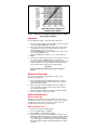
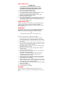
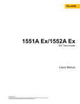
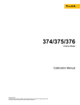
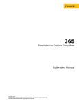
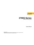
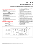
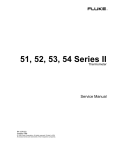
®
80T-150UA
Universal Temperature Probe
Instruction Sheet
0U
5
T-1
OBE
PR
80
RE
TU
RA
MPE
TE
CF
F
OF
Introduction
The Model 80T-150UA Universal Temperature Probe is a self-contained
temperature-to-voltage converter. The probe is designed to provide a
direct temperature reading when it is connected to any high impedance
DMM that is capable of 1 mV resolution and at least a 300-count full
scale readout capability. Output is 1 mV per degree (Celsius or
Fahrenheit). Two switch-selected temperature output scalings are
provided: -50 to +150 °C or -58 to +302 °F. The probe will stand off 60 V
dc or 30 V ac rms (42.4 V peak).
The unit is housed in two separate but attached assemblies: a
temperature probe and a temperature-to-voltage converter. The probe
contains the temperature-sensing element and is electrically connected to
the temperature-to-voltage converter through a 46-inch cable. A threeposition switch on the converter acts as a power switch and is used for
selecting Celsius or Fahrenheit scaling for the output. Two banana plugs
with standard 0.75-inch spacing are provided for connecting the 80T150UA to the DMM.
Operating power for the 80T-150UA is derived from a standard 9 V
battery. Typically, an alkaline battery provides more than 600 hours of
continuous operation before replacement is necessary. An OFF switch is
provided on the temperature-to-voltage converter to allow battery
conservation when the unit is not in use. In addition, the OFF position of
the power switch allows the battery condition to be determined via the
external DMM.
Temperature is measured by exposing the probe tip directly to the
material to be measured (non-corrosive liquid, gas, or solid). A direct
temperature reading is displayed on the DMM.
Symbols
XWarning:
Risk of electric shock. Refer to the manual for
information.
W Attention: Refer to the manual for information about this
feature.
PN 3208738
February 2008
© 2008 Fluke Corporation. All rights reserved.
All product names are trademarks of their respective companies.
Specifications
The 80T-150UA will achieve rated accuracy when it is used with any
0.25 % DMM that has an input impedance of ≥1 MΩ.
Electrical
Measurement Range: (See Probe Limitations)
-50 to +150 °C
-58 to +302 °F
Accuracy: (Applies for one year after purchase or calibration)
AMBIENT °C
+15 to +35 °C
ACCURACY
±1 °C from 0 to +100 °C, decreasing
linearly to ±3 °C at -50 and +150 °C
0 to +15 °C and
+35 to +50 °C
±2 °C from 0 to +100 °C,
decreasing linearly to ±4 °C at -50
and +150 °C
AMBIENT °F
+59 to +95 °F
ACCURACY
±1.8 °F from +32 to +212 °F,
decreasing linearly to ±5.4 °F at -58
and +302 °F
+32 to +59 °F and
+95 to +122 °F
±3.6 °F from +32 to +212 °F,
decreasing linearly to ±7.2 °F at -58
and +302 °F
Sensitivity (80T-150UA output): 1 mV dc / °C or °F
Voltage Standoff: 60 V dc or 30 V ac rms (42.4 V peak)
Settling Time: 9.5 seconds to settle within 2 ° for a 50 ° change
RF Field: The 80T-150UA product is unspecified in environments with
EMC fields greater than 100 mV/meter. ESD performance is specified as
Criteria C per EN61326.
Environmental
Ambient Operating Range for Temperature Module: 0 to +50 °C
(+32 to +122 °F)
Maximum Temperature Probe Body and Cable: +70 °C
(+160 °F) See Probe Limitations
Minimum Temperature Probe Body and Cable:
Minimum Operating Temperature for Cable: -12 °C (+10 °F)
Minimum Operating Temperature for Probe Body: -40 °C (-40 °F)
See Probe Limitations
Storage Temperature for Unit: -40 to +70 °C (-40 to +160 °F)
Humidity: 0 % to 90 % (0 °C to +35 °C)
0 % to 70 % (+35 °C to +50 °C) (noncondensing)
Altitude:
Operating: ≤3048 m ( ≤10,000 ft)
Storage: ≤15240 m (≤50,000 ft)
Application Force: 15 pounds maximum (probe tip to measured surface)
General
Weight: 150 g (5.3 oz)
Overall Length: 53.8 inch (1.36 m)
Battery: Standard 9 V battery (NEDA #1604,6F22,006P)
Battery Life: 600+ hours, typical (Alkaline Battery), 6.5 V minimum
Output Termination: Standard 0.75-inch spaced double banana plug
Probe Material: Glass-filled valox
Probe Size: 0.6 inch maximum diameter
Tip Material: Nickle Plated Copper
Tip Size: 0.31 cm (0.12 inch diameter)
Operating Notes
The following paragraphs are intended to familiarize the operator with
the 80T-150UA. The operator should read these paragraphs before
attempting to operate the probe.
Probe Limitations
The 80T-150UA probe is constructed of a highly durable plastic and is
suitable for measuring the temperature of liquids, gases, and solid
surfaces up to 150 °C. When measuring temperature, observe the
following precautions to prevent damage to the probe:
1.
Do not expose the probe end (probe tip plus about 2 inches of the
probe body) to temperatures exceeding +150 °C (+302 °F). The
remainder of the probe body should not be exposed to temperatures
above +70 °C (+160 °F).
2.
Do not expose the probe end (probe tip plus about 2 inches of the
probe body) to temperatures below -50 °C (-58 °F). The remainder
of the probe body should not be exposed to temperatures below
-40 °C (-40 °F).
3.
For liquid measurements, recommended applications range from
water, lubricants, and fuels to most solvents. Liquids as shallow as
1.27 cm (0.5 inch) can be measured since the temperature sensor is
inch the probe tip.
XWWarning
To avoid electrical shock, do not use this instrument when
voltages exceeding 60 V dc or 30 V ac rms (42.4 V peak )
are present. The probe tip is electrically connected to the
output terminals.
WCaution
Long-term exposure of the probe to corrosive
environments will result in pitting and deterioration of the
aluminum probe tip. If equipment is used in a manner not
specified by the manufacturer, the protection provided by
the equipment may be impaired.
Error Sources
When the probe tip is applied to a solid surface, it draws or sinks heat
from the surface. Therefore, if the measured surface has a low mass
(e.g., a transistor case), the indicated temperature may be lower than
the actual temperature.
Similarly, a steady-state error or gradient exists between the measured
surface and the sensing device in the probe tip. This is due to the flow of
heat from the measurement surface to the probe body. The effect of the
steady-state error increases as the differential between ambient and
surface temperature increases.
To determine the actual surface temperature of a device, both the heatsinking and steady-state errors must be considered. The correction curve
given in Figure 1 approximates the effect of both error sources on TO-3,
TO-5, and TO-18 transistor cases.
F1.eps
Figure 1. Initial Case Temperature Above Ambient vs Meter
Reading Above Ambient
Operation
Use the following procedure to operate the 80T-150UA probe:
1.
Connect the banana plugs on the 80T-150UA to the input terminals
of a high impedance DMM. Observe polarity.
2.
Select a dc voltage range that will provide at least 1 mV resolution
(1 mV/degree) and a full scale readout that will encompass the
expected temperature. The 2 V range of a
3 1/2-digit DMM is adequate. Ignore readings of less than 1° when
a more sensitive DMM is used.
3.
Set the 80T-150UA power switch to °C or °F, and energize the
DMM.
4.
Firmly touch the probe tip to the surface to be measured, or expose
it to a liquid or gas. The DMM will display the temperature in
degrees. Vary the probe angle and pressure when measuring solid
surface temperatures. The highest stabilized reading will be the
most accurate. (See the following measuring technique.)
WCaution
The force exerted on the probe tip should not exceed 15
pounds.
Measuring Technique
Here are some suggestions for improving the accuracy of your
temperature measurements:
1.
When measuring higher than ambient temperatures, adjust the
connection between the probe and the surface until you get the
highest temperature reading.
2.
When measuring lower than ambient temperatures, adjust the
connection between the probe and the surface until you get the
lowest temperature reading.
3.
When measuring near ambient temperatures, make the reading
when the multimeter readout is most stable.
General Maintenance
Access Information
The battery and the calibration pots are located on the interior of the
temperature-to-voltage converter assembly. Access to these locations is
accomplished by removing the screw from the bottom side of the
assembly and removing the top of the plastic box.
Battery Condition Test
1.
Set the power switch to the OFF position.
2.
Connect the 80T-150UA to the DMM.
3.
Set the DMM to the 200 or 400 mV dc range.
4.
Read the battery test voltage on the DMM or test instrument. For
DMMs with 10 MΩ input impedance, a minimum reading of 100 mV
is acceptable. For test instruments with 1 MΩ input impedances,
®
such as ScopeMeter , a minimum reading of 75 mV is acceptable,
With these minimum readings, approximately 100 hours of battery
life remain.
Battery Replacement
XWWarning
To avoid electrical shock, remove the probe from the
measurement surface before opening the case. Totally
reassemble the instrument before attempting to use it.
1.
2.
3.
4.
5.
6.
Set the power switch to the OFF position.
Disconnect the 80T-150UA from the DMM.
Turn the 80T-150UA so the power switch is facing down. Remove
the single screw located between the banana plugs.
Grasp one case half in each hand. Pull the two halves apart,
beginning at the end with the banana plugs.
Remove and replace the battery.
Reassemble the 80T-150UA as follows. Mate the two case halves at
the end where the cable enters the case, then "hinge" the two
halves together. Replace the case screw, being careful not to pinch
the probe cable or battery wires.
Performance Test
Complete the calibration procedure without opening the temperature-tovoltage converter assembly and without making any calibration
adjustments. Observe the readings given in [brackets]. Other readings
are for calibration only.
Calibration
The calibration cycle of one year is recommended to maintain the unit
within the specifications given earlier. The equipment required for
calibration is listed in the table following the calibration procedure.
Note
Values given in brackets apply to the Performance Test.
Perform the following steps to calibrate the 80T-150UA:
1.
Access the interior of the temperature-to-voltage converter by
removing the bottom case screw and separating the case halves.
2. Connect the 80T-150UA to a DVM with 10 μV resolution, and select
mV dc range.
3. Select the °C position of the switch. Immerse the probe tip 5.1 cm (2
inches) into a mercury thermometer monitored 0 °C bath, and allow
a full 5 minutes for the reading to stabilize.
4. Adjust VR3 and VR1 (see Figure 2) to obtain the following reading:
0.00 ±0.05 mV dc [0 ±0.2 mV dc]
5. Select the °F position of the switch, and adjust VR2 to obtain the
following reading:
32.0 ±0.1 mV dc [32.0 ±0.4 mV dc]
6. Select the °C position, and move the probe tip to a 70 °C bath and
again allow the reading to stabilize.
7. Adjust VR4 to obtain a DVM reading that agrees with the bath
temperature (BT) as monitored by a mercury thermometer.
°C BT ±0.05 mV dc [BT ±0.2 mV dc]
8. Select the °F position, and verify that the output is within ±4 mV dc
of the bath thermometer reading. If necessary, change the DVM
range to obtain an on-scale reading.
9. Return the probe tip to the 0 °C bath wait 10 minutes, then check the
output. If readjustment is necessary, repeat steps 4 through 8 until
the readings can be obtained without adjustment.
10. Set the 80T-150UA switch to the OFF position, and remove the 80T150UA from the DVM.
11. Reassemble the 80T-150UA.
12. The 80T-150UA is now calibrated.
Cleaning
Clean the test tool with a damp cloth and a mild soap. Do not use
abrasives, solvents, or alcohol. These may damage the text on the test
tool.
Sensing Probe and Cable Assembly
VR2
VR4 VR3 VR1
MP101
MP102
F4.eps
Figure 2. 80T-150UA Temperature Probe
Test Equipment Requirements
Instrument Type
Minimum Use
Specifications
Recommended
Model
Mercury Thermometer
0.1 °C Resolution
Princo Model SAMACP45
Dewar Flask and Cap
1-Pint Capacity (for Ice Bath)
Thermos Bottle
Metal or Glass Container
1-Pint Capacity
Suitable for Boiling
Water
Digital Voltmeter
100 mV Range with 10 μV
Resolution
Fluke Model 8845A
1000 mV Range with 100 μV
To contact Fluke or for service, call one of the following telephone numbers:
USA: 1-888-44-FLUKE (1-888-443-5853), Canada: 1-800-36-FLUKE (1-800-3635853), Europe: +31 402-675-200, Japan: +81-3-3434-0181, Singapore: +65-7385655, Anywhere in the world: +1-425-446-5500
Or, visit Fluke's Web site at www.fluke.com.
Fluke Corporation
Fluke Europe B.V.
P.O. Box 9090
P.O. Box 1186
Everett WA 98206-9090
5602 B.D. Eindhoven
USA
The Netherlands
LIMITED WARRANTY & LIMITATION OF LIABILITY
Each Fluke product is warranted to be free from defects in material and workmanship under
normal use and service. The warranty period is one year and begins on the date of shipment.
Parts, product repairs and services are warranted for 90 days. This warranty extends only to the
original buyer or end-user customer of a Fluke authorized reseller, and does not apply to fuses,
disposable batteries or to any product which, in Fluke's opinion, has been misused, altered,
neglected or damaged by accident or abnormal conditions of operation or handling. Fluke
warrants that software will operate substantially in accordance with its functional specifications for
90 days and that it has been properly recorded on non-defective media. Fluke does not warrant
that software will be error free or operate without interruption.
Fluke authorized resellers shall extend this warranty on new and unused products to end-user
customers only but have no authority to extend a greater or different warranty on behalf of Fluke.
Warranty support is available if product is purchased through a Fluke authorized sales outlet or
Buyer has paid the applicable international price. Fluke reserves the right to invoice Buyer for
importation costs of repair/replacement parts when product purchased in one country is submitted
for repair in another country.
Fluke's warranty obligation is limited, at Fluke's option, to refund of the purchase price, free of
charge repair, or replacement of a defective product which is returned to a Fluke authorized
service center within the warranty period.
To obtain warranty service, contact your nearest Fluke authorized service center or send the
product, with a description of the difficulty, postage and insurance prepaid (FOB Destination), to
the nearest Fluke authorized service center. Fluke assumes no risk for damage in transit.
Following warranty repair, the product will be returned to Buyer, transportation prepaid (FOB
Destination). If Fluke determines that the failure was caused by misuse, alteration, accident or
abnormal condition of operation or handling, Fluke will provide an estimate of repair costs and
obtain authorization before commencing the work. Following repair, the product will be returned to
the Buyer transportation prepaid and the Buyer will be billed for the repair and return
transportation charges (FOB Shipping Point).
THIS WARRANTY IS BUYER'S SOLE AND EXCLUSIVE REMEDY AND IS IN LIEU OF ALL
OTHER WARRANTIES, EXPRESS OR IMPLIED, INCLUDING BUT NOT LIMITED TO ANY
IMPLIED WARRANTY OF MERCHANTABILITY OR FITNESS FOR A PARTICULAR PURPOSE.
FLUKE SHALL NOT BE LIABLE FOR ANY SPECIAL, INDIRECT, INCIDENTAL OR
CONSEQUENTIAL DAMAGES OR LOSSES, INCLUDING LOSS OF DATA, WHETHER
ARISING FROM BREACH OF WARRANTY OR BASED ON CONTRACT, TORT, RELIANCE OR
ANY OTHER THEORY.
Since some countries or states do not allow limitation of the term of an implied warranty, or
exclusion or limitation of incidental or consequential damages, the limitations and exclusions of
this warranty may not apply to every buyer. If any provision of this Warranty is held invalid or
unenforceable by a court of competent jurisdiction, such holding will not affect the validity or
enforceability of any other provision.