1
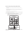
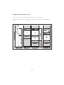
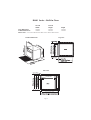
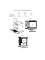
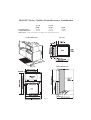
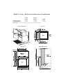
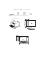
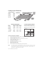
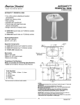
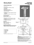
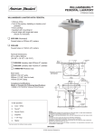
IMPORTANT! PLEASE MAKE THIS INFORMATION AVAILABLE TO YOUR JOINER AS IT COULD REDUCE YOUR INSTALLATION COST. Fisher & Paykel INSTALLATION INFORMATION Built-In Ovens BI601 Series - Built-In Oven BI601D Series - Built-In Double Oven BI601XC2 Series - Built-In Oven/Microwave Combination BI451 Series - Built-In Compact Oven CAUTION: In order to avoid a hazard these appliances must be installed according to these Installation Instructions. Please follow installation information carefully. If in doubt consult your local building authority by-laws. BEFORE YOU START DO Ensure a suitable disconnection switch is incorporated in the permanent wiring, mounted and positioned to comply with the local wiring Rules and Regulations. DO Ensure that the location of the Oven connection socket is outside the installation space if the appliance is flush to the rear wall. DO Ensure the benchtop and the Oven cavity are square and level. DO Ensure the electrician allows as least 1.5m free length of connection cable within the cavity for ease of installation and service of the Oven. DO Use easy to clean finishes for the wall surfaces surrounding the Oven and Cooktop to aid removal of any cooking fume staining resulting from use of the Oven and Cooktop. DO Ensure that the interconnection cord between the Cooktop and the Oven is not accessible via cupboard doors after installation. This applies to any extension cords as well, even though they are double insulated. DO Consult local building authorities and by-laws if in doubt regarding installation. DO Check the height from the floor suits the user. DO Ensure the cavity is a completely sealed box with no gaps. This will ensure the cooling air flows under the product to give the correct venting and cooling for the oven and cabinet surround. Page 1 BUILT-IN OVEN INSTALLATION INSTRUCTIONS 1. Check that the kitchen cavity is square and within the limits in the INSTALLATION DIMENSIONS. 2. Lift oven and slide into place. Secure Oven in cavity using 4 'wood screws' and washers supplied through enamelled frame at either side of oven as shown in Flush Fitting Installation Diagram. 3. Check that the Oven is firmly secured in the kitchen unit. 4. When installing the oven it is essential to centre the product in the cavity giving a spacing of 2.5mm from the door edge to the joinery. NOTE: If installing a Cooktop above the Oven ensure adequate clearance is provided for the Cooktop as per the Cooktop Manufacturer's Instructions. If installing a BI601 Single Built-In Oven with Wall Trim Kit, ensure you use instructions that accompany that kit, Part No. 447915. Flush Fitting Installation Diagrams Cabinetry adjacent to ovens must have a minimum temperature rating of 90°C as stated in AS/NZS 3350.2.6 Page 2 Height Recommendation Guide Figures are based on an average height of 1650mm (5'5") wearing shoes. The height of the product may vary + 50mm according to the height of the most frequent user. Page 3 BI601 Series - Built-In Oven Overall Overall Width Height Oven Dimensions 595mm 595mm Cabinet Dimensions 568mm 585mm Please Note: Oven front dimensions differ from cabinet dimensions. Product Dimensions Depth 562mm 550mm Top View Side View Page 4 BI601D Series - Built-In Double Oven Overall Overall Width Height Oven Dimensions 595mm 932mm Cabinet Dimensions 568mm 922mm Please Note: Oven front dimensions differ from cabinet dimensions. Product Dimensions Depth 562mm 550mm Top View Side View Page 5 BI601XC2 Series - Built-In Oven/Microwave Combination Overall Overall Width Height Oven Dimensions 595mm 932mm Cabinet Dimensions 568mm 935mm Please Note: Oven front dimensions differ from cabinet dimensions. Product Dimensions Depth 562mm 550mm Top View Cabinet Detail View Side View Page 6 BI601XC Series - Built-In Oven/Microwave Combination Overall Overall Width Height Oven Dimensions 595mm 932mm Cabinet Dimensions 568mm 935mm Please Note: Oven front dimensions differ from cabinet dimensions. Product Dimensions Depth 562mm 550mm Top View Cabinet Detail View Side View Page 6 BI451 Series - Built-In Compact Oven Overall Overall Width Height Oven Dimensions 595mm 450mm Cabinet Dimensions 568mm 440mm Please Note: Oven front dimensions differ from cabinet dimensions. Product Dimensions Depth 562mm 550mm Top View Side View Page 7 Part No. 540784C August 2001 INSTALLATION INSTRUCTIONS FOR CT560X, CT560C, CT5602F, CT2802, CT6552S, & BICT600 SERIES COOKTOPS IMPORTANT! PLEASE MAKE THIS INFORMATION AVAILABLE TO YOUR JOINER AS IT COULD REDUCE YOUR INSTALLATION COST. CAUTION: In order to avoid a hazard these appliances must be installed according to these Installation Instructions. BEFORE YOU START DO Ensure a suitable disconnection switch is incorporated in the permanent wiring, mounted and positioned to comply with the Local Wiring Rules and Regulations. DO Ensure the bench is square and level. DO Use easy to clean finishes for the wall surfaces surrounding the Cooktop to aid removal of any cooking fume staining resulting from use of the Cooktop. DO Consult local building authorities and by-laws if in doubt regarding installation. DO Ensure that the interconnection cord between the Cooktop and the Oven or control Box is not accessible via cupboard doors after installation. This applies to any extension cord as well, even though they are double insulated. Note: Ensure that there is a minimum of 60mm between the cutout and the rear or side wall. If the cutout is less than 100mm from the wall, some form of protection against heat should be used, such as ceramic tiles. If prolonged use is anticipated, or the cooktop is mounted above a drawer space, a barrier between is recommended. The CT560X should not be installed directly above a dishwasher as the humidity may damage the electronics. Cooktop Cutout Dimensions MINIMUM DEPTHS CT560X 60mm CT560C 60mm CT5602F 60mm CT2802 60mm CT6552S 65mm BICT600 50mm COOKTOP DIMENSIONS TYPE CT560X CT560C CT5602F CT2802 CT6552S (Cooktop) (Controls) BICT600 LENGTH 578mm 578mm 578mm 289mm WIDTH 511mm 511mm 511mm 511mm DEPTH 51mm 51mm 51mm 55mm 578mm 88mm 578mm 511mm 511mm 511mm 45mm 63mm 45mm CT6552S Control Box Installation · · · · · · · · · · Note: CLAMPING DOWN COOKTOP Place the cooktop into the cutout and tighten with the supplied clamps. These will cope with bench thickness 15-50mm. 20mm min. 50mm Remove the brackets from the cooktop and the box. Place the cooktop in the cutout. Feed the cooktop wiring harness up through the box cutout. Remove Control Box cover. Connect the cooktop wiring harness. Clamp the wiring harness. Wire the mains to the box and clamp. Replace Control box cover. Roll the box into the cutout. Secure control box and cooktop using brackets provided. Two small brackets are provided that screw to the sides of the control box. These must be used to clamp the control box down to the joinery. Three brackets are provided for clamping down the cooktop. Part No. 599049B September 2000