1
36 CF ST/Pier
Gas Fireplace
Tested and Listed by
OMNI-Test Laboratories, Inc.
Portland, Oregon
Report # 028-F-87-5
ANSI Z21.88a-2007
•
Built-In Direct Vent Fireplace
•
Natural Gas or Propane
•
Residential or Mobile Home
•
Bedroom Approved
WARNING: If the information in these instructions is not followed exactly, a fire or
explosion may result causing property damage, personal injury or loss of life.
- Do not store or use gasoline or other flammable vapors and liquids in the vicinity of this or
any other appliance.
WHAT TO DO IF YOU SMELL GAS
• Do not try to light any appliance.
• Do not touch any electrical switch; do not use any phone in your building.
• Immediately call gas supplier from a neighbor's phone. Follow the gas supplier's
instructions.
• If you cannot reach your gas supplier, call the fire department.
- Installation and service must be performed by a qualified installer, service agency or the
gas supplier.
This appliance may be installed in an aftermarket permanently located, manufactured home (USA only)
or mobile home, where not prohibited by local codes.
This appliance is only for use with the type(s) of gas indicated on the rating plate. A conversion kit is
supplied with the appliance.
Installation Manual
Installer:
After installation give this manual to the homeowner and explain operation of this heater.
Copyright 2009, T.I.
$10.00
100-01212_000
4090102
www.travisproducts.com
4800 Harbour Pointe Blvd. SW
Mukilteo, WA 98275
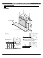
2
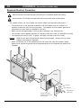
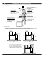
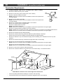
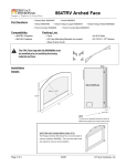
Introduction
Overview
This manual details the installation
requirements for the 36 CF ST and Pier
fireplace. For operating and maintenance
instructions, refer to the 36 CF ST/Pier Owner's
Manual (part # 100-01213).
Listing Details
This appliance was listed by OMNI Test Labs to
ANSI Z21.88 - report # 028-F-87-5. The listing
label is attached to the appliance near the gas
control valve. A copy is shown to the right.
ICBO Approval
This appliance was listed by OMNI-Test
Laboratories - ICBO # TL130.
Massachusetts Approval
This manual has been submitted to the
Massachusetts Board of State Examiners of
Plumbers and Gas Fitters
National Fireplace Institute
Figure 1
© Travis Industries
4090102
100-01212_000
Table of Contents
Introduction
3
Installation (continued)
Overview ................................................................. 2
Listing Details.......................................................... 2
Safety Precautions
Safety Precautions ................................................... 4
Vent Requirements .................................................. 19
Approved Vent...................................................... 19
Altitude Considerations .......................................... 19
Vent Clearances ................................................... 20
Vent Installation.................................................... 19
Packing List............................................................. 7
Approved Vent Configurations:
Exhaust Restrictor Adjustment................................ 21
Vent Location ....................................................... 21
Rear Vent, Horz. Term. (1 45° Elbow)....................... 22
Rear Vent, Horz. Term. (1 45°, 2 90° Elbows)............ 23
Rear Vent, Horz. Term. (1 45°, 4 90° Elbows)............ 24
Rear Vent, Vert. Term. (1 45°, 3 90° Elbows) ............ 25
Top Vent, Horz. Term. (1 45°, 1 90° Elbow) ............... 26
Top Vent, Horz. Term. (1 45°, 3 90° Elbows) ............. 27
Top Vent, Vert. Term. (1, 3, or 5 45° Elbows) ............ 28
Top Vent, Vert. Term. (1 45°, 2 90° Elbows) .............. 29
Additional Items Required.......................................... 7
Termination Requirements......................................... 30
Recommended Installation Procedure ......................... 7
Hearth Requirements ............................................... 31
Hearth Requirements – Recessed Hearth ................ 32
Features and Specifications
Installation Options................................................... 6
Specifications .......................................................... 6
Dimensions ............................................................. 6
Installation
Massachusetts Requirements ..................................... 8
Preparing the Fireplace Stand-offs .............................. 9
Fireplace Placement Requirements............................. 10
Clearances...........................................................10
Raised Fireplaces .................................................10
Minimum Framing 36 CF ST (See Through) ...............11
Framing Dimensions – 36 CF Pier ...........................12
Attaching Stand-Offs to Framing .............................13
Facing Requirements ............................................... 33
Non-Combustible Facing........................................ 34
Mantel Requirements................................................ 35
Finalizing the Installation
Steps for Finalizing the Installation ............................. 36
Required Electrical Connection................................... 14
Air Shutter Adjustment.............................................. 37
Battery Pack / Learn Switch Installation ....................... 15
Steps for Installing the Battery Box and Learn Switch..16
Battery Installation ................................................16
Glass Frame Removal and Installation........................ 38
Remote Synchronization............................................ 17
Gas Line Requirements............................................. 18
Gas Line Connection .............................................18
Gas Inlet Pressure ................................................18
Log Set Installation .................................................. 39
LP Conversion Instructions ....................................... 43
Power Heat Duct Installation...................................... 47
Andiron Installation................................................... 47
Index
Index...................................................................... 48
© Travis Industries
4090102
100-01212_000
4
Safety Precautions
Safety Warnings:
•
Failure to follow all of the requirements may result in property damage, bodily injury, or even death.
•
This unit must be installed by a qualified installer to prevent the possibility of an explosion.
•
This appliance must be installed in accordance with all local codes, if any; if not, in U.S.A. follow ANSI
Z223.1 and NFPA 54(88).
•
A manufactured home (USA only) or mobile home OEM installation must conform with the
Manufactured Home Construction and Safety Standard, Title 24 CFR, Part 3280, or, when such a
standard is not applicable, the Standard for Manufactured Home Installations, ANSI/NCSBCS A225.1,
or Standard for Gas Equipped Recreational Vehicles and Mobile Housing, CSA Z240.4. This
appliance may be installed in Manufactured Housing only after the home is site located.
•
All exhaust gases must be vented outside the structure of the living-area. Combustion air is drawn
from outside the living-area structure. The venting must not be connected to a chimney flue serving a
separate solid-fuel burning appliance.
•
Notify your insurance company before hooking up this fireplace.
•
The room heater should be inspected before use and at least annually by a qualified service person.
More frequent cleaning may be required due to excessive lint from carpeting, bedding material, etc.
•
The instructions in this manual must be strictly adhered to. Do not use makeshift methods or
compromise in the installation. Improper installation will void the warranty and safety listing.
•
This heater is approved for use with natural gas (NG) or propane (LP). Burning the incorrect fuel will
void the warranty and safety listing and may cause an extreme safety hazard. Direct questions about
the type of fuel used to your dealer. Check the label and flame adjust knob on the gas control valve.
•
Contact your local building officials to obtain a permit and information on any installation restrictions or
inspection requirements in your area.
•
If the flame becomes sooty, dark orange in color, or extremely tall, do not operate the heater. Call your
dealer and arrange for proper servicing.
•
It is imperative that control compartments, screens, or circulating air passageways of the heater be
kept clean and free of obstructions. These areas provide the air necessary for safe operation.
•
Do not operate the heater if it is not operating properly in any fashion or if you are uncertain. Call your
dealer for a full explanation of your heater and what to expect.
•
Do not store or use gasoline or other flammable liquids in the vicinity of this heater.
•
Do not operate if any portion of the heater was submerged in water or if any corrosion occurs.
•
Do not place clothing or other flammable items on or near the heater. Because this heater can be
controlled by a thermostat there is a possibility of the heater turning on and igniting any items placed
on or near it.
•
Light the heater using the built-in igniter. Do not use matches or any other external device to light
your heater.
•
Never remove, replace, modify or substitute any part of the heater unless instructions are given in this
manual. All other work must be done by a trained technician. Don't modify or replace orifices.
•
The viewing glass should be opened only for conducting service.
•
Any safety screen or guard removed for servicing must be replaced prior to operating the heater.
© Travis Industries
4090102
100-01212_000
Safety Precautions
5
Safety Warnings (continued):
•
Allow the heater to cool before carrying out any maintenance or cleaning.
•
Operate the heater according to the instructions included in this manual.
•
If the main burners do not start correctly turn the gas off at the gas control valve and call your dealer for
service.
•
This unit is not for use with solid fuel.
•
Do not place anything inside the firebox (except the included logs).
•
If the fiber logs become damaged, replace with Travis Industries log set.
•
Do not throw this manual away. This manual has important operating and maintenance instructions
that you will need at a later time. Always follow the instructions in this manual.
•
Do not touch the hot surfaces of the heater. Educate all children of the danger of a high-temperature
heater. Young children should be supervised when they are in the same room as the heater.
•
Due to the high temperature, the heater should be located out of traffic and away from furniture and
draperies.
•
Instruct everyone in the house how to shut gas off to the appliance and at the gas main shutoff valve.
The gas main shutoff valve is usually next to the gas meter or propane tank and requires a wrench to
shut off.
•
Travis Industries, Inc. grants no warranty, implied or stated, for the installation or
maintenance of your heater, and assumes no responsibility of any consequential
damage(s).
© Travis Industries
4090102
100-01212_000
6
Features and Specifications
Installation Options
•
•
•
•
•
Residential or Mobile Home
Flush or Recessed Face
Raised or Floor Placement
Horizontal or Vertical Vent
Bedroom Approved
Specifications
Natural Gas
58,000
27,000
Maximum BTU Input Per Hour
Minimum BTU Input on Low
Propane
58,000
27,000
Dimensions
56-1/2" *
8-5/8" Outside Diameter
33" *
22-1/2"
1" *
See "Vent
Location" for
38"
Fro
n
t
Rig
ht
ft
Le
details
62-1/2"
Ba
ck
3/4"
Weight: 270 Lbs.
* Includes the 1" standoffs below the baseplate.
Figure 2
© Travis Industries
4090102
100-01212_000
Installation
7
(for qualified installers only)
Packing List
•
•
•
•
•
•
•
•
Glass LatchTool
Log Set with Embers and Rock Wool
Remote Control with Wall Mount
LP Conversion Kit (2 orifices and 1 rate screw)
Battery Box
Learn Switch with 12’ Battery Box Wire
Andiron Brackets (4)
Fiber Board
Additional Items Required
•
•
•
•
Firebacks (SKU 96100177 or 96100178)
1080/36 CF Direct Vent (available only from Travis Industries – see page 19 for part numbers)
Gas Line Equipment (shutoff valve, pipe, etc.)
Electrical Equipment
Recommended Installation Procedure
1. Frame the opening for the fireplace. We suggest omitting the framing above the header to
allow for easier vent installation.
2. Place the fireplace in place, making sure it is level and plumb. Attach using the nailing
brackets.
3. Install the vent, electrical connection, gas line, and battery box. Install power heat duct (if
being used).
4. Install the framing above the header.
5. Install the hearth (if applicable).
6. Install the included non-combustible facing.
7. Install the facing.
8. Install the mantel (if applicable).
9. Finalize the installation (see page 36).
© Travis Industries
4090102
100-01212_000
8
Installation
(for qualified installers only)
Massachusetts Requirements
NOTE: The following requirements reference various Massachusetts and national codes not contained in this document.
Requirements for the Commonwealth of Massachusetts
For all side wall horizontally vented gas fueled equipment installed in every dwelling, building or structure used in whole or in
part for residential purposes, including those owned or operated by the Commonwealth and where the side wall exhaust vent
termination is less than seven (7) feet above finished grade in the area of the venting, including but not limited to decks and
porches, the following requirements shall be satisfied:
Installation of Carbon Monoxide Detectors
At the time of installation of the side wall horizontal vented gas fueled equipment, the installing plumber or gasfitter shall
observe that a hard wired carbon monoxide detector with an alarm and battery back-up is installed on the floor level where the
gas equipment is to be installed. In addition, the installing plumber or gasfitter shall observe that a battery operated or hard
wired carbon monoxide detector with an alarm is installed on each additional level of the dwelling, building or structure served
by the side wall horizontal vented gas fueled equipment. It shall be the responsibility of the property owner to secure the
services of qualified licensed professionals for the installation of hard wired carbon monoxide detectors.
In the event that the side wall horizontally vented gas fueled equipment is installed in a crawl space or an attic, the hard wired
carbon monoxide detector with alarm and battery back-up may be installed on the next adjacent floor level.
In the event that the requirements of this subdivision can not be met at the time of completion of installation, the owner shall
have a period of thirty (30) days to comply with the above requirements; provided, however, that during said thirty (30) day
period, a battery operated carbon monoxide detector with an alarm shall be installed.
Approved Carbon Monoxide Detectors
Each carbon monoxide detector as required in accordance with the above provisions shall comply with NFPA 720 and be
ANSI/UL 2034 listed and IAS certified.
Signage
A metal or plastic identification plate shall be permanently mounted to the exterior of the building at a minimum height of eight
(8) feet above grade directly in line with the exhaust vent terminal for the horizontally vented gas fueled heating appliance or
equipment. The sign shall read, in print size no less than one-half (1/2) inch in size, “GAS VENT DIRECTLY BELOW. KEEP
CLEAR OF ALL OBSTRUCTIONS”.
Inspection
The state or local gas inspector of the side wall horizontally vented gas fueled equipment shall not approve the installation
unless, upon inspection, the inspector observes carbon monoxide detectors and signage installed in accordance with the
provisions of 248 CMR 5.08(2)(a)1 through 4.
Exemptions
The following equipment is exempt from 248 CMR 5.08(2)(a)1 through 4:
• The equipment listed in Chapter 10 entitled “Equipment Not Required To Be Vented” in the most current edition of NFPA 54 as
adopted by the Board; and
• Product Approved side wall horizontally vented gas fueled equipment installed in a room or structure separate from the
dwelling, building or structure used in whole or in part for residential purposes.
MANUFACTURER REQUIREMENTS
Gas Equipment Venting System Provided
When the manufacturer of Product Approved side wall horizontally vented gas equipment provides a venting system design or
venting system components with the equipment, the instructions provided by the manufacturer for installation of the
equipment and the venting system shall include:
• Detailed instructions for the installation of the venting system design or the venting system components; and
• A complete parts list for the venting system design or venting system.
Gas Equipment Venting System NOT Provided
When the manufacturer of a Product Approved side wall horizontally vented gas fueled equipment does not provide the parts
for venting the flue gases, but identifies “special venting systems”, the following requirements shall be satisfied by the
manufacturer:
• The referenced “special venting system” instructions shall be included with the appliance or equipment installation
instructions; and
• The “special venting systems” shall be Product Approved by the Board, and the instructions for that system shall include a
parts list and detailed installation instructions.
A copy of all installation instructions for all Product Approved side wall horizontally vented gas fueled equipment, all venting
instructions, all parts lists for venting instructions, and/or all venting design instructions shall remain with the appliance or
equipment at the completion of the installation.
See Gas Connection section for additional Commonwealth of Massachusetts requirements.
© Travis Industries
4090102
100-01212_000
Installation
9
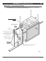
(for qualified installers only)
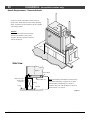
Preparing the Fireplace Stand-offs
This appliance is shipped with the header and side stand-offs in the retracted position. These standoffs must be placed in their upright position prior to installing the fireplace. Secure the stand-offs to
the framing with screws or other fasteners.
WARNING: Failure to correctly erect the stand-offs may lead to a serious fire-hazard and will void
the listing and warranty of this fireplace.
b
c
a
d
e
Figure 3
© Travis Industries
4090102
100-01212_000
10
Installation
(for qualified installers only)
Fireplace Placement Requirements
•
Fireplace must be placed in a room with a minimum 96” ceiling.
•
Fireplace must be placed directly on the sub-floor or wood platform (not on linoleum or carpet).
•
Fireplace must be installed on a level surface capable of supporting the fireplace and vent.
•
This heater may be placed in a bedroom. Please be aware of the large amount of heat this
appliance produces when determining a location.
Clearances
•
When installed, walls that protrude to the sides of the fireplace must be a minimum 12” from the
glass frame (tile stop).
•
Due to the high temperature, the heater should be located out of traffic and away from furniture
and draperies.
•
Fireplace must be placed so the vents below and above the glass do not become blocked.
Raised Fireplaces
•
The fireplace (and hearth, if desired) may be placed on a platform designed to support the
fireplace and vent.
Minimum 78” Fireplace
Enclosure Height.
AAAAAAA
AAAAAAA
AAAAAAA
AAAAAA
AAAAAAA
AAAAAA
AAAAAA
AAAAAAA
AAAA
AAAAAA
AAAAAA
AAAAAAA
AAAAAA
AAAA
AAA
AAAAAA
AAAAAA
AAAA
AAA
AAAAAAA
Platform
Optional Raised Hearth
(see “Hearth Requirements” for details)
Figure 4
© Travis Industries
4090102
100-01212_000
Installation
11
(for qualified installers only)
Minimum Framing 36 CF ST (See Through)
Minimum 78” Fireplace
Vent Clearances:
Enclosure Height
8-5/8" Diameter vent requires 3-1/2" clearance
to the sides. You may need to notch the
framing to accommodate this clearance.
NOTE:
If venting to the rear using a 45° elbow directly
15-5/8"
We recommend you install the
off the fireplace, the vent will be 42-1/4" above
framing after placing the fireplace in
the base of the fireplace.
position.
As an alternative, you may omit the
framing above one side and back of the
fireplace until the fireplace is in position
(shown in gray).
56-1/2"
Fro
nt
Rig
ht
42-1/4"
62-1/2"
22-1/2"
ft
Le
Ba
ck
Figure 5
© Travis Industries
4090102
100-01212_000
12
Installation
(for qualified installers only)
Framing Dimensions – 36 CF Pier
Vent Clearances:
8-5/8" Diameter vent requires 3-1/2" clearance to
the sides. You may need to notch the framing to
accommodate this clearance.
Minimum 78” Fireplace
15-5/8"
Enclosure Height
18-1/4"
NOTE: Do not build into
this area - it must be left
Glass
clear to provide
Centerline
adequate clearance for
the vent.
56-1/2”
49-3/8”
22-1/2”
Fro
nt
Rig
ht
ft
Le
Ba
ck
Figure 6
© Travis Industries
4090102
100-01212_000
Installation
(for qualified installers only)
13
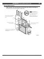
Attaching Stand-Offs to Framing
b
c
a
d
e
Figure 7
© Travis Industries
4090102
100-01212_000
14
Installation
(for qualified installers only)
Required Electrical Connection
Make sure power to the heater has been turned off prior to installation (disable the breaker).
Do not connect 110-120 VAC to the gas control valve or the on/off circuit on this fireplace.
This fireplace utilizes 110 VAC to power the receiver module and intermittent pilot system.
•
The electrical line to the grounded receptacle inside the fireplace must be installed by a
qualified installer and must meet all local codes. The fireplace must be properly grounded in
accordance with local codes (or ANSI/NFPA 70-1987).
•
Make sure the household breaker is shut off prior to working on any electrical lines.
•
The fireplace must be properly grounded in accordance with local codes (or ANSI/NFPA 70-1987)
•
The electrical line must be a min. 14 gauge, and supply 120 Volts at 60 Hz (2 Amps)
Caution:
•
Label all wires prior to disconnection when servicing controls. Wiring errors can cause
improper and dangerous operation.
Attach an electrical line to the receptacle inside the control box (see the illustration below).
Make sure to connect the ground wire to the grounding tab on the receptacle (this grounds the
fireplace).
Control Box
Cover Plate
Romex Connector
Grounded 110V
Power Supply
Attach the electrical line,
including the grounding wire,
to this receptacle.
© Travis Industries
4090102
100-01212_000
Installation
15
(for qualified installers only)
Battery Pack / Learn Switch Installation
•
The battery pack and learn switch must be mounted inside a junction box in a location that
may be reached by the 12’ long battery box wires (see Figure 8).
Do not route the wires over the top
of the fireplace.
Battery Box and Learn Switch
(placed inside the junction box)
Junction Box
(not supplied)
Staple the two wires near the junction
box. This prevents the wires from
slipping out of the junction box while
the batteries are replaced. Take care
to prevent damage to wires.
Remote Holder - used to cover the
junction box. It is removed to
replace batteries and access the
learn switch
Battery Box Wire
Wire Length = 12'
Remove the Control Box to access the battery box wire. See the
illustration on the following page for wiring details.
Figure 8
© Travis Industries
4090102
100-01212_000
16
Installation
(for qualified installers only)
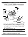
Steps for Installing the Battery Box and Learn Switch
1. Remove the control cover and attach the 12’ long battery box wire to the quick connects on the
receiver module (see Figure 9 below). Route the battery box wire through the opening below
the cover. At this time make sure the continuous pilot switch is set to “OFF” and the remote
switch is set to “REMOTE” on the receiver module – item “a”). You may also wish to verify all
the wire leads are fully attached.
Pilot Assembly
Battery Box
Igniter ("I") Wire
(Orange - with
fiberglass
insulation)
(external junction box)
Receiver
Module
Learn Wires
Two White Wires
Sensor ("S")
Wire (White)
Motor Wires (for flame height adjustment)
Red, Yellow, White, and Blue wires
Le
ar
n
R
TO
O
M
I
C
O
M
Battery Wires
Red and White Wires
M
.
S
ER
W
PO
AD
AC Adapter
(wire orientation does not matter)
ot
J
ff
O
e/
us
uo
tin ot n
on il
C P ff/O
O
em
R
a
Gas Control Valve
Black
Brown Switch
Wires (not
used)
Make sure continuous pilot
is set to "OFF" and remote
is set to "REMOTE".
Ground
Accent Light Wires
Orange and White Wires
Main Burner Control Wires
Auxiliary Power
(Not Used)
White
Green
Orange
White
Pilot Flame Control Wires
Power Input
Make sure continuous pilot
is set to "OFF" and remote
is set to "REMOTE".
120V Extension Module
Figure 9
2. Determine a location for the single-gang junction box that contains the battery pack and learn
switch. It must be located within 12’ of the fireplace. Mount the junction box.
3. Insert the battery box wires through the junction box, leaving approximately 8” of slack so the
battery pack may be removed and the batteries replaced. Use a staple or other means to
secure the wiring to the framing – this prevents the wires from slipping out of the junction box in
the event the wires become disconnected from the battery pack (see Figure 8). NOTE: The
wiring is low-voltage (6V) and does not require a strain relief. Connect the learn switch and
battery pack wires (see Figure 9).
4. Place batteries inside the battery pack and place it inside the junction box. Attach the remote
holder to the junction box with the included screws.
INSTALLATION WARNING – Remote Synchronization
At this time we highly recommend you verify the remote and fireplace are synchronized. This
process requires access to the learn switch. See the instructions on page 17 for details.
Battery Installation
This fireplace uses four AA batteries for operation during power outages. Place the batteries into
the battery box. In addition, two AAA batteries are required for the transmitter.
© Travis Industries
4090102
100-01212_000
Installation
17
(for qualified installers only)
Remote Synchronization
The fireplace is shipped with the remote and fireplace pre-synchronized. Do not
synchronize the remote unless you are 100% sure it does not work correctly.
Synchronizing the Remote
NOTE: The fireplace must have power and the transmitter must have batteries to complete this process.
WARNING: Shut the gas off to the fireplace prior to conducting this process.
1
Press the “Learn” button once. The fireplace will beep once.
2
Press the “Mode” button on the remote. The fireplace will beep five times to indicate
synchronization.
NOTE: Re-setting the Receiver Module
If the receiver module fails to synchronize with the remote after two attempts, you should re-set the
receiver module. To do this, hold down the LEARN button for approximately 10 seconds until the
receiver beeps 3 times. This indicates the receiver has been re-set and can be synchronized using
the instructions above.
© Travis Industries
4090102
100-01212_000
18
Installation
(for qualified installers only)
Gas Line Requirements
MASSACHUSETTS INSTALLATIONS - WARNING:
THIS PRODUCT MUST BE INSTALLED BY A LICENSED PLUMBER OR GAS FITTER WHEN INSTALLED WITHIN
THE COMMONWEALTH OF MASSACHUSETTS.
OTHER MASSACHUSETTS CODE REQUIREMENTS:
•
Flexible connector must not be longer than 36 inches.
•
Shutoff valve must be a “T” handle gas cock.
•
Only direct vent sealed combustion products are approved for bedrooms or bathrooms.
•
Fireplace dampers must be removed or welded in the open position prior to the installation of a fireplace insert or gas
log.
•
A carbon monoxide (CO) detector is required in the same room as the appliance.
•
The gas line must be installed in accordance with all local codes, if any; if not, follow ANSI 223.1 and the
requirements listed below.
•
The fireplace and gas control valve must be disconnected from the gas supply piping during any pressure
testing of that system at test pressures in excess of 1/2 psig. For pressures under 1/2 psig, isolate the
gas supply piping by closing the manual shutoff valve.
•
Leak test all gas line joints and the gas control valve prior to and after starting the fireplace.
•
This fireplace is designed either for natural gas or for propane (but not for both). Make sure the correct fuel is
used.
•
An accessible manual shut-off valve (“t” handle gas cock) is required within 6’ of the fireplace.
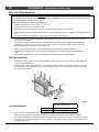
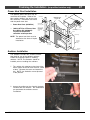
Gas Line Connection
•
Installation must be performed by a qualified installer, service agency or the gas supplier (In Massachusetts
a licensed plumber/gasfitter).
•
A shutoff valve is built into the fireplace. It is located on the back side of the fireplace and acts as the gas
inlet connection. After installing the gas line (and testing), remove the cover plate shown below and turn the
gas shutoff valve to “ON”.
Gas Line
(1/2" M.P.T.)
NOTE: This cover plate
may be removed to access
the shut-off valve.
Figure 10
Standard Input Pressure
Gas Inlet Pressure
Natural Gas
Propane
7" W.C. (1.74 kPA)
13" W.C. (2.73 kPA)
•
If the pressure is not sufficient, make sure the piping used is large enough, the supply regulator is
adequately adjusted, and the total gas load for the residence does not exceed the amount supplied.
•
The supply regulator (the regulator that attaches directly to the residence inlet or to the propane tank) should
supply gas at the suggested input pressure listed above. Contact the local gas supplier if the regulator is at
an improper pressure.
© Travis Industries
4090102
100-01212_000
Installation
19
(for qualified installers only)
Vent Requirements
•
•
•
•
The gas appliance and vent system must be vented directly to the outside of the building, and
never be attached to a chimney serving a separate solid fuel or gas-burning appliance. Each
direct vent gas appliance must use it's own separate vent system.
In addition to the requirements listed here, follow the requirements provided with the vent.
A firestop is required whenever the vent penetrates a floor or ceiling (or passes through
horizontal framing members). A thimble is required whenever the vent passes through a wall (or
horizontal framing members).
Venting installation instructions may be found at www.duravent.com. Keep the vent
instructions, along with this manual, with the appliance for future reference.
Approved Vent
•
This fireplace may only use the following vent components (8-5/8” / 6” external diameter coaxial vent). These parts are available from Travis Dealers.
6” Length
12” Length
24” Length
36” Length
48” Length
4” to 8” Adjustable Length (Slip Connector)
45° Elbow
90° Elbow
Wall Thimble
Fire Stop
Elbow Strap
Wall Strap
Adjustable Roof Flashing (0/12 to 6/12)
Adjustable Roof Flashing (7/12 to 12/12)
Storm Collar
Vinyl Siding Stand-off
Horizontal Termination
Vertical Termination
Simpson Part #
68GSS-06
68GSS-12
68GSS-24
68GSS-36
68GSS-48
68GSS-12A
68GSS-L45
68GSS-L90
68G-SS-WT
68G-SS-FS
68G-SS-ES
68G-SS-WS
68G-SS-F
68G-SS-SF
68G-SS-SC
68GSS-VSS
68G-SS-HC
68G-SS-VC
Travis Part #
98900024
98900023
98900022
98900021
98900020
98900025
98900026
98900027
98900030
98900029
98900028
98900031
98900035
98900036
98900032
98900037
98900033
98900034
Altitude Considerations
•
This heater has been tested at altitudes ranging from sea level to 6,000 feet. In this testing we have found
that the heater, with its standard orifice, burns correctly with just an air shutter adjustment.
•
Failure to adjust the air shutter properly may lead to improper combustion which can create a safety hazard.
Consult your dealer or installer if you suspect an improperly adjusted air shutter.
Vent Installation
•
Slide the vent sections together and turn 1/4 turn until the sections lock
in place.
•
Screws are not required to secure the vent. However, three screws may
be used to secure vent sections together if desired.
•
High temperature sealant is recommended at the appliance starter
section connection (use high-temperature silicone or Mill-Pac®).
•
If disassembly is required, at time of re-assembly check to see if the vent
creates a tight fit. If it does not, apply high temperature sealant to the
joints of the affected sections.
•
Horizontal sections require a 1/4" rise every 12" of travel
•
Horizontal sections require non-combustible support every three feet (e.g.: plumbing tape)
© Travis Industries
4090102
100-01212_000
20
Installation
(for qualified installers only)
Vent Clearances
ABOVE THE ENCLOSURE (over 78")
Vertical Sections:
1" Clearance To the Side
Vertical Penetrations
Horizontal Sections:
(through ceilings, roofs, etc.)
4" Clearance Above
(firestop is required - sku 98900029)
2" Clearance To The Side
1" Clearance To the Side
2" Clearance Below
Horizontal Penetrations
(through walls, etc.)
IN THE ENCLOSURE (under 78")
(thimble is required - sku 98900030)
Vertical or Horizontal Sections:
4" Clearance Above
6" Clearance Above
2" Clearance To The Side
3-1/2" Clearance To The Side
2" Clearance Below
2" Clearance Below
Vent Location
The starter section is set at a 45° angle. Place a 45° elbow directly on top of the fireplace and route it
vertically or horizontally. The approximate position of the vent is shown below.
REAR VENT
TOP VENT
1"
3-1/2"
46"
41-3/4"
Framing to the rear of the fireplace.
Framing to the rear of the fireplace.
9-1/4"
NOTE: In cases where the vent is routed vertically
directly above the fireplace, you may place a 90°
elbow directly on top of the fireplace, followed by a
45° elbow that directs the vent upwards. For vent
56"
configuration purposes this is considered a top vent
and the 90° and 45° elbow is considered a single
45° elbow.
© Travis Industries
4090102
100-01212_000
Installation
(for qualified installers only)
21
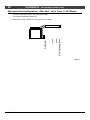
Approved Vent Configurations
Exhaust Restrictor Adjustment
An exhaust restrictor is built into exhaust vent at the rear of the fireplace. It is used to adjust the flow rate of
exhaust gases. Depending upon vent configuration, you may be required to adjust the restrictor. The
charts for acceptable vent configurations detail the correct vent restrictor position. The restrictor is
accessed from inside the firebox (remove the glass to gain access). To adjust the restrictor, remove the
nut and bolt holding the restrictor in position, rotate the restrictor to the correct position, then replace the
nut and bolt to secure (see Figure 11).
Position # 2
Position # 3
Position # 4
The fireplace ships in
restrictor position # 1.
Position # 5
Figure 11
© Travis Industries
4090102
100-01212_000
22
Installation
(for qualified installers only)
The vent must not exceed 5 feet (see chart below).
•
Use Exhaust Restrictor Position # 1.
•
Horizontal sections require a 1/4" rise every 12" of travel
0 feet
•
5 feet (max)
Approved Vent Configuration – Rear Vent, Horz. Term. (1 45° Elbow)
Figure 12
© Travis Industries
4090102
100-01212_000
Installation
23
(for qualified installers only)
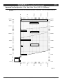
Approved Vent Configuration – Rear Vent, Horz. Term. (1 45°, 2 90° Elbows)
30 feet
(max.)
20' (max)
15 feet
5 feet
10 feet
The termination must fall within the shaded area shown in the chart. Use the indicated restrictor
positions.
0 feet
•
AAAAAAAAAAAAAAAAA
AAAAAAAAAAAAAAAAA
AAAAAAAAAAAAAAAAA
AAAAAAAAAAAAAAAAA
AAAAAAAAAAAAAAAAA
AAAAAAAAAAAAAAAAA
AAAAAAAAAAAAAAAAA
AAAAAAAAAAAAAAAAA
AAAAAAAAAAAAAAAAA
AAAAAAAAAAAAAAAAA
AAAAAAAAAAAAAAAAA
AAAAAAAAAAAAAAAAA
AAAAAAAAAAAAAAAAA
AAAAAAAAAAAAAAAAA
AAAAAAAAAAAAAAAAA
AAAAAAAAAAAAAAAAA
AAAAAAAAAAAAAAAAA
AAAAAAAAAAAAAAAAA
AAAAAAAAAAAAAAAAA
AAAAAAAAAAAAAAAAA
30 feet
(max.)
Exhaust Restrictor # 3
25 feet
25 feet
Exhaust Restrictor # 2
20 feet
15 feet
20 feet
15 feet
Exhaust Restrictor # 1
10 feet
5 feet
10 feet
5 feet
0 feet
20' (max)
15 feet
10 feet
5 feet
0 feet
0 feet
Figure 13
© Travis Industries
4090102
100-01212_000
24
Installation
(for qualified installers only)
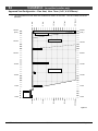
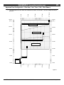
Approved Vent Configuration – Rear Vent, Horz. Term. (1 45°, 4 90° Elbows)
30 feet
(max.)
20' (max)
15 feet
5 feet
10 feet
The termination must fall within the shaded area shown in the chart. Use the indicated restrictor
positions.
0 feet
•
AAAAAAAAAAAAAAAAA
AAAAAAAAAAAAAAAAA
AAAAAAAAAAAAAAAAA
AAAAAAAAAAAAAAAAA
AAAAAAAAAAAAAAAAA
AAAAAAAAAAAAAAAAA
AAAAAAAAAAAAAAAAA
AAAAAAAAAAAAAAAAA
AAAAAAAAAAAAAAAAA
AAAAAAAAAAAAAAAAA
AAAAAAAAAAAAAAAAA
AAAAAAAAAAAAAAAAA
AAAAAAAAAAAAAAAAA
AAAAAAAAAAAAAAAAA
AAAAAAAAAAAAAAAAA
AAAAAAAAAAAAAAAAA
AAAAAAAAAAAAAAAAA
AAAAAAAAAAAAAAAAA
AAAAAAAAAAAAAAAAA
AAAAAAAAAAAAAAAAA
Exhaust Restrictor # 3
30 feet
(max.)
Exhaust Restrictor # 2
25 feet
20 feet
15 feet
25 feet
20 feet
15 feet
Exhaust Restrictor # 1
10 feet
5 feet
10 feet
5 feet
0 feet
20' (max)
15 feet
10 feet
5 feet
0 feet
0 feet
Figure 14
© Travis Industries
4090102
100-01212_000
Installation
25
(for qualified installers only)
Approved Vent Configuration – Rear Vent, Vert. Term. (1 45°, 3 90° Elbows)
30 feet
(max.)
20' (max)
15 feet
5 feet
10 feet
The termination must fall within the shaded area shown in the chart. Use the indicated restrictor
positions.
0 feet
•
AAAAAAAAAAAAAAAAA
AAAAAAAAAAAAAAAAA
AAAAAAAAAAAAAAAAA
AAAAAAAAAAAAAAAAA
AAAAAAAAAAAAAAAAA
AAAAAAAAAAAAAAAAA
AAAAAAAAAAAAAAAAA
AAAAAAAAAAAAAAAAA
AAAAAAAAAAAAAAAAA
AAAAAAAAAAAAAAAAA
AAAAAAAAAAAAAAAAA
AAAAAAAAAAAAAAAAA
AAAAAAAAAAAAAAAAA
AAAAAAAAAAAAAAAAA
AAAAAAAAAAAAAAAAA
AAAAAAAAAAAAAAAAA
30 feet
(max.)
Exhaust Restrictor # 3
25 feet
25 feet
Exhaust Restrictor # 2
20 feet
15 feet
20 feet
15 feet
Exhaust Restrictor # 1
10 feet
10 feet
10 feet
20' (max)
0 feet
15 feet
0 feet
5 feet
5 feet
0 feet
5 feet
Figure 15
© Travis Industries
4090102
100-01212_000
26
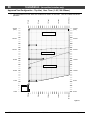
Installation
(for qualified installers only)
Approved Vent Configuration – Top Vent, Horz. Term. (1 45°,1 90° Elbows)
30 feet
(max.)
20' (max)
15 feet
10 feet
5 feet
The termination must fall within the shaded area shown in the chart. Use the indicated restrictor
positions.
0 feet
•
AAAAAAAAAAAAAAAAA
AAAAAAAAAAAAAAAAA
AAAAAAAAAAAAAAAAA
AAAAAAAAAAAAAAAAA
AAAAAAAAAAAAAAAAA
AAAAAAAAAAAAAAAAA
AAAAAAAAAAAAAAAAA
AAAAAAAAAAAAAAAAA
AAAAAAAAAAAAAAAAA
AAAAAAAAAAAAAAAAA
AAAAAAAAAAAAAAAAA
AAAAAAAAAAAAAAAAA
AAAAAAAAAAAAAAAAA
AAAAAAAAAAAAAAAAA
AAAAAAAAAAAAAAAAA
AAAAAAAAAAAAAAAAA
AAAAAAAAAAAAAAAAA
AAAAAAAAAAAAAAAAA
AAAAAAAAAAAAAAAAA
AAAAAAAAAAAAAAAAA
AAAAAAAAAAAAAAAAA
30 feet
(max.)
Exhaust Restrictor # 3
25 feet
20 feet
25 feet
20 feet
Exhaust Restrictor # 2
15 feet
15 feet
Exhaust Restrictor # 1
10 feet
5 feet
10 feet
5 feet
0 feet
20' (max)
15 feet
10 feet
5 feet
0 feet
0 feet
Figure 16
© Travis Industries
4090102
100-01212_000
Installation
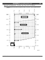
27
(for qualified installers only)
Approved Vent Configuration – Top Vent, Horz. Term. (1 45°, 3 90° Elbows)
30 feet
(max.)
20' (max)
15 feet
10 feet
5 feet
The termination must fall within the shaded area shown in the chart. Use the indicated restrictor
positions.
0 feet
•
AAAAAAAAAAAAAAAAA
AAAAAAAAAAAAAAAAA
AAAAAAAAAAAAAAAAA
AAAAAAAAAAAAAAAAA
AAAAAAAAAAAAAAAAA
AAAAAAAAAAAAAAAAA
AAAAAAAAAAAAAAAAA
AAAAAAAAAAAAAAAAA
AAAAAAAAAAAAAAAAA
AAAAAAAAAAAAAAAAA
AAAAAAAAAAAAAAAAA
AAAAAAAAAAAAAAAAA
AAAAAAAAAAAAAAAAA
AAAAAAAAAAAAAAAAA
AAAAAAAAAAAAAAAAA
AAAAAAAAAAAAAAAAA
AAAAAAAAAAAAAAAAA
AAAAAAAAAAAAAAAAA
AAAAAAAAAAAAAAAAA
AAAAAAAAAAAAAAAAA
AAAAAAAAAAAAAAAAA
30 feet
(max.)
Exhaust Restrictor # 3
25 feet
20 feet
15 feet
Exhaust Restrictor # 2
25 feet
20 feet
15 feet
Exhaust Restrictor # 1
10 feet
5 feet
10 feet
5 feet
0 feet
20' (max)
15 feet
10 feet
5 feet
0 feet
0 feet
Figure 17
© Travis Industries
4090102
100-01212_000
28
Installation
(for qualified installers only)
Approved Vent Configuration – Top Vent, Vert. Term. (1, 3, or 5 45° Elbows)
40 feet
(max.)
35 feet
30 feet
20' (max)
15 feet
10 feet
5 feet
The termination must fall within the shaded area shown in the chart. Use the indicated restrictor
positions.
0 feet
•
AAAAAAAAAAAAAAA
AAAAAAAAAAAAAAA
AAAAAAAAAAAAAAA
AAAAAAAAAAAAAAA
AAAAAAAAAAAAAAA
AAAAAAAAAAAAAAA
AAAAAAAAAAAAAAA
AAAAAAAAAAAAAAA
AAAAAAAAAAAAAAA
AAAAAAAAAAAAAAA
AAAAAAAAAAAAAAA
AAAAAAAAAAAAAA
AAAAAAAAAAAAAAA
AAAAAAAAAAAAAA
AAAAAAAAAAAAAAA
AAAAAAAAAAAAAA
AAAAAAAAAAAAAA
AAAAAAAAAA
AAAAAAAAAA
AAAAAAAAAAAAAA
AAAAAAAAAAAAAA
AAAAAAAAAA
AAAAAAAAAA
40 feet
(max.)
35 feet
30 feet
Exhaust Restrictor # 3
25 feet
20 feet
15 feet
Exhaust Restrictor # 2
25 feet
20 feet
15 feet
Exhaust Restrictor # 1
0 feet
20' (max)
0 feet
15 feet
5 feet
10 feet
5 feet
5 feet
10 feet
0 feet
10 feet
Figure 18
© Travis Industries
4090102
100-01212_000
Installation
29
(for qualified installers only)
Approved Vent Configuration – Top Vent, Vert. Term. (1 45°,2 90° Elbows)
40 feet
(max.)
35 feet
30 feet
20' (max)
15 feet
10 feet
5 feet
The termination must fall within the shaded area shown in the chart. Use the indicated restrictor
positions.
0 feet
•
AAAAAAAAAAAAAAAAA
AAAAAAAAAAAAAAAAA
AAAAAAAAAAAAAAAAA
AAAAAAAAAAAAAAAAA
AAAAAAAAAAAAAAAAA
AAAAAAAAAAAAAAAAA
AAAAAAAAAAAAAAAAA
AAAAAAAAAAAAAAAAA
AAAAAAAAAAAAAAAAA
AAAAAAAAAAAAAAAAA
AAAAAAAAAAAAAAAAA
AAAAAAAAAAAAAAAAA
AAAAAAAAAAAAAAAAA
AAAAAAAAAAAAAAAAA
AAAAAAAAAAAAAAAAA
AAAAAAAAAAAAAAAAA
AAAAAAAAAAAAAAAAA
AAAAAAAAAAAAAAAAA
A
AAAAAAAAAAAAAAAAA
A
AAAAAAAAAAAAAAAAA
A
40 feet
(max.)
35 feet
30 feet
Exhaust Restrictor # 3
25 feet
20 feet
25 feet
20 feet
Exhaust Restrictor # 2
15 feet
15 feet
0 feet
20' (max)
0 feet
15 feet
5 feet
10 feet
5 feet
5 feet
10 feet
0 feet
10 feet
Figure 19
© Travis Industries
4090102
100-01212_000
30
Installation
(for qualified installers only)
Termination Requirements
!
Venting terminals shall not be recessed into a wall or siding.
A
Minimum 9" clearance from any door or window
B
Minimum 12" above any grade, veranda, porch, deck or balcony
C
Minimum 3-3/8" from outside corner walls
NOTE: Clearance in accordance with local installation codes and the requirements
of the gas supplier.
Roof
Surface
11” Min.
6” Min.
Roof
Eaves
D
Minimum 12" from inside corner walls
NOTE: Clearance in accordance with local installation codes and the requirements
of the gas supplier.
E
Minimum 11" clearance below unventilated soffits or roof surfaces
Minimum 18" clearance below ventilated soffits
Minimum 6" clearance below roof eaves
NOTE: Vinyl surfaces require 24"
NOTE: Clearance in accordance with local installation codes and the requirements of the gas supplier.
F
Minimum 12" clearance below a veranda, porch, deck or balcony
NOTE: Permitted only if veranda, porch, deck, or balcony is fully open on a minumum of two sides beneath the floor.
NOTE: Clearance in accordance with local installation codes and the requirements of the gas supplier.
G
Minimum 48" clearance from any adjacent building
H
Minimum 84" clearance above any grade when adjacent to public walkways or driveways
NOTE: may not be used over a walkway or driveway shared by an adjacent building
I
Minimum 9" clearance to any nonmechanical air supply inlet to the building or the combustion air inlet to any other
appliance.
J
Minimum 36" clearance above any mechanical air supply inlet if within 10’ horizontally
K
Minimum 36" from the area above the meter/regulator (vent outlet)
NOTE: Clearance in accordance with local installation codes and the requirements of the gas supplier.
L
Minimum 36" from the meter/regulator (vent outlet)
NOTE: Clearance in accordance with local installation codes and the requirements of the gas supplier.
M
Minimum 12” above the roof line (for vertical terminations)
N
Minimum 24” horizontal clearance to any surface (such as an exterior wall) – for vertical terminations
E
N
M
E
E
A
K
G
J
A
F
H
D
I
C
L
B
NOTE: Measure clearances to the nearest edge of the exhaust hood.
•
Use the vinyl siding standoff when installing on an exterior with vinyl siding.
•
Vent termination must not be located where it will become plugged by snow or other material
© Travis Industries
4090102
100-01212_000
Installation
31
(for qualified installers only)
Hearth Requirements
NOTE: Whenever using a hearth over 1” thick, the fireplace will need to be raised.
Flush Hearth
Non-Combustible Hearth
Min. 3/4”
Max 1”
AAAAAAAAAAAAAA
AAAAAAAAAAA
AAAAAAAAAAAAAA
AAAAAAAAAAA
AAAAAAAAAAAAAA
AAAAAAAAAAA
AAAAAAAAAAAAAA
AAAAAAAAAAA
AAAAAAAAAAAAAA
AAAAAAAAAAAAAAA
AAAAAAAAAAAAAA
AAAAAAAAAAA
AAAAAAAAAAAAAA
AAAA
AAAAAAAAAAAAAAA
AAAAAAAAAAAAAA
Min. 64” (on ST, Pier will vary)
Min.10”
Side View
Fireplace
Tile
AAAAAAA
1”
Cement Board
Hearth Material over 1” Thick
NOTE: Do not build a hearth more than the 1” maximum above the
Fireplace
AAAAAAA
AAAAAAA
AAAAAA
A
AAA
AAAAAAA
AAAAAA
AAA
A
AAA
AAA
AAA
A
AAA
AAA
AAA
A
AAA
AAA
AAAAAAA
AAAAAAAAAAAAAA
AAAAAAAAA
A
AAAAAAAAAAAAAA
(granite, concrete, etc.)
base of the fireplace (it must fit under the glass frame).
1”
Plywood (OSB, etc.)
Fireplace
Marble
1”
Framing
Sub-Floor
© Travis Industries
4090102
Figure 20
100-01212_000
32
Installation
(for qualified installers only)
Hearth Requirements – Recessed Hearth
A hearth is not required if the fireplace is raised 6” above the
flooring surface. NOTE: Make sure to accommodate the flooring
surface - this distance must be measured from the top of carpeting
or other flooring material.
WARNING:
AAAAAAAAAAAAAAAA
AAAAAAAAAAAAAAAA
AAAAAAA
AAAAAAAAAAAAAAAA
A
AAAAAAA
AAAAAAAAAAAAAAAA
AAAAAAAAAAAAA
A
AA
AAAAAAA
AAAA
AAAAAAAAAAAAAAAA
A
AAAAAAAAAAAAA
A
AA
AAAAAAA
AAAA
AA
A
AAAAAAAAAAAAAAAA
A
AA
A
AAAAAAAAAAAAA
A
AA
AAAAAAA
AA
AAAA
AA
A
AAAAAAAAAAAAAAAA
A
AA
A
A
A
AAAAAAAAAAAAA
AAAAAAA
AA
AAAA
AA
A
AAAAAAAAAAAAAAAA
A
A
AA
A
AA
A
AAAAAAAAAAAAA
AAAAAAAAAAAAAAAA
A
AA
A
AAAAAAAAAAAAA
AAAAAAAAAAAAAAAA
AAAAAAAAAAAAA
AAAAAAAAAAAAA
AAAAAAAAA
AAA
AAAA
AAAA
AAAA
AAAAAAAAA
AAAA
We recommend a hearth to protect the flooring
surface from discoloration or other negative
impact from the heater, especially if it is near the
minimum raised height.
Min. 6”
Side View
Fireplace
Cement Board
1”
Minimum 6” to top of
flooring surface
(carpet, etc.)
Carpet
Plywood (OSB, etc.)
NOTE: When building a raised fireplace, consider the facing
material below the fireplace. If using tile, you may wish to
Framing
make the platform a suitable height for un-cut tile. For
example, if using 12” tile, make the platform 11” tall (10-1/2”
Sub-Floor
section of framing + 1/2” plywood).
Figure 21
© Travis Industries
4090102
100-01212_000
Installation
33
(for qualified installers only)
Facing Requirements
•
Attach the included fiber board (or other non-combustible) to the fireplace and framing (see
Figure 22 below). This non-combustible facing must extend from the base of the fireplace to
the header and to the framing members on both sides.
WARNING: Do not use adhesive to
secure the cement board or facing. The
Adh
esiv
e
high temperatures of the fireplace may
cause adhesives to emit odors. Use
mastic or thin set (or other non-
Attach the included non-combustible fiber
board to the fireplace and framing as
shown.
Use screws to secure the fiber
board to the fireplace.
Fiber Board (or other non-combustible) is
required from the glass frame edge to the
side framing (13”).
Drywall
AAA
AAA
AAA
AAA
AAA
AAA
AAA
AAA
AAA
AAA
AAA
combustible, non-odorous adherent) to
attach the facing to the cement board.
Fiber
Board
Flanges are provided on the fireplace
for the screws to attach to.
Figure 22
© Travis Industries
4090102
100-01212_000
34
Installation
(for qualified installers only)
Non-Combustible Facing
•
Non-combustible facing on the front of the fireplace must extend a minimum 16-1/2” from the
top of the glass frame (49-1/2” from the base of the fireplace). Above 16-1/2” combustible
facing may be used (see “Mantel Requirements” on the following page for more details).
•
Non-combustible facing on the front of the fireplace must extend a minimum 2” to each side of
the glass frame. Beyond 2” combustible facing may be used, but may not protrude more than
4” (see “Mantel Requirements” on the following page for more details).
•
The maximum depth for non-combustible facing is 6” (includes the fiber board).
Combustible Material
(drywall, etc.)
A
A
A
A
A
A
A
A
A
AA
A
AA
A
AA
A
AA
A
AA
A
AA
A
AA
A
AA
A
AA
A
Fiber Board (required)
16-1/2”” Min.
Non-Combustible Facing
(tile, rock, marble, etc.)
Fireplace
Glass Frame
Figure 23
© Travis Industries
4090102
100-01212_000
Installation
35
(for qualified installers only)
Mantel Requirements
•
The mantel (combustible or non-combustible) must be a minimum 49-1/2” above the base of
the fireplace (see Figure 24).
•
The maximum mantel depth is 12” (measured from the face).
Mantel
(combustible or non-combustible)
Max. 12”
SEE THROUGH
Min. 49-1/2”
Combustible mantel columns (legs) that
protrude less than 4” (measured from the
fiber board) must be 2” from the glass frame.
If the mantel columns protrude more than 4”,
they must meet the sidewall clearance (12”
from the glass frame).
Non-combustible mantel columns do not
have a minimum clearance.
Base of the Fireplace
Mantel
(combustible or non-combustible)
Max. 12”
Max. 12”
PIER
Min. 49-1/2”
Base of the Fireplace
Figure 24
© Travis Industries
4090102
100-01212_000
36
Finalizing the Installation
(for qualified installers only)
Steps for Finalizing the Installation
WARNING: Prior to removing the glass, shut off gas to the
appliance (or remove the batteries from the battery box and shut
off electricity to the fireplace). This prevents any chance of
accidental burner ignition when accessing the firebox.
1. Remove the glass (see page 38).
NOTE: If using propane (LP) convert the appliance prior to installing the logs (see page 43
for details)..
2. We recommend you purge the gas line at this time (with the glass removed). This allows gas to
be detected once it enters the firebox, ensuring gas does not build up.
3. Install the firebacks (see instructions included with firebacks) and logs (see page 39).
4. Turn on the gas to the fireplace. Turn on gas to the heater. Leak test all gas joints.
5. Replace the glass. Start the pilot.
6. Start the main burner. Leak test all gas joints again (the gas control valve and connections are
located on the exterior of the fireplace on the left side.
© Travis Industries
4090102
100-01212_000
Finalizing the Installation
(for qualified installers only)
37
7. Check the air shutter following the directions below.
Air Shutter Adjustment
Let the heater burn for fifteen minutes (make sure the logs and glass are in place). The flames should
be yellow with no sooting. Adjust the air shutter, if necessary, to achieve the correct looking flame.
Correct
Flames should be blue at the
base, yellow-orange on the top.
Not Enough Air
If the flames are too tall or sooty on the
ends, open the air shutter.
Too Much Air
If the flames are all blue and
short, close the air shutter.
How to Adjust the Air Shutter
The three air shutters (two sides and center) are located to the back of the burner (under the exhaust)
and are accessed by removing the glass frame (and the rear log, if needed – see the picture below).
The air shutter levers may be adjusted – a screwdriver of other tool may be used to “tap” the lever to
the desired position. Slide the shutter towards the back (exhaust) to close, to the front (towards the logs)
to open. After adjusting the air shutter replace the glass and verify flame quality.
8. Adjust the flame height to its highest position - the flames should not contact the top of the
firebox. Check the flame on lowest position. The flames should burn off each burner hole. If
the heater does not work correctly, contact your Travis dealer for a remedy.
9. Give this manual to the home owner for future reference and fully explain operation of this
heater. For comprehensive operating and maintenance instructions, refer to the Owner's
Manual.
© Travis Industries
4090102
100-01212_000
38
Finalizing the Installation
(for qualified installers only)
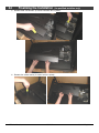
Glass Frame Removal and Installation
WARNING: Prior to removing the glass, shut off gas to the appliance (or remove the
batteries from the battery box and shut off electricity to the fireplace). This
prevents any chance of accidental burner ignition when accessing the firebox.
Warning:
The appliance must
be completely cool before removing
the glass.
Warning:
the glass.
Do not strike or slam
Remove the glass trim (see
directions to the right).
The glass frame is held in place with
two latches along the top and two
slots, with brackets, along the
bottom. Insert the glass latch tool
into the latch, pull it forward and up
to detach the latches (see pictures
below). Once the latches are free,
pivot the frame out and lift it off the
brackets at the bottom of the glass
frame.
AAA
AAAAAA
AAA
AAA
AAA
AAA
AAA
AAA
AAAAAA
AAA
AAA
AAAAAA
AAA
AAA
AAA
AAA
AAA AAA
AAA
AAA
AAA
AAA
AAA
AAA
AAA
AAA
AAA
AAA
AAA
Glass Frame
Glass Trim
Attach the glass trim to the glass frame by
inserting the hooks on the trim over the
studs on the glass frame. When properly
aligned, the frame will push straight in
and drop into place.
Figure 25
© Travis Industries
4090102
100-01212_000
Finalizing the Installation
(for qualified installers only)
39
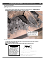
Log Set Installation
Ember Placement
Place the embers along the firebox floor and burner to help conceal the burner. Make sure none of
the embers are directly over the burner holes. See the photo below.
Note how the embers do not
cover any burner holes. Place
the embers around the burner
to create a realistic effect.
Rock Wool Placement
The rock wool must be pulled apart and made into a thin gauze prior to placing over the burner.
See the illustration below for details.
NOTE: Propane (LP) units use a lighter amount of rock wool than natural gas units.
Preparing the Rock Wool:
AAA
A
The rock wool comes in one
clump. Tear off “dime” sized
clumps and flatten. Then pull on
Place small pieces of rock wool next to the burner holes in
visible locations. Place the rock wool sparingly so it does
not cover large areas of the burner.
the wool to create gauze-like
pieces. The wool glows best
when very thin and porous.
WARNING: If the rock wool is too thick or placed so it
obstructs the flow of gas, sooting will occur.
© Travis Industries
4090102
100-01212_000
40
Finalizing the Installation
(for qualified installers only)
Log Installation
NOTE: The logs are a mirror-image (same logs fit on left and right side). Both the 36 CF See
Through (ST) and Pier use the same log set. See the pictures below for log placement
Bottom 3 logs.
Middle 2 logs.
© Travis Industries
4090102
100-01212_000
Finalizing the Installation
(for qualified installers only)
41
Top 2 logs (last 2 logs)
Picture from opposite side
© Travis Industries
4090102
100-01212_000
42
Finalizing the Installation
(for qualified installers only)
Picture from end (Pier only)
© Travis Industries
4090102
100-01212_000
Finalizing the Installation
(for qualified installers only)
43
LP Conversion Instructions
Install the conversion kit prior to installing the fireplace to ensure proper gas use.
1
Remove the glass (see page 36). Remove the logs and coals (if installed - page 39)
2
Remove the grate (4 screws hold it in place).
3
Remove the two shelves on the side of the orifice cover (2 screws hold each one in place).
4
Remove the orifice cover (the plate over the air shutter levers – 2 screws hold it in place).
© Travis Industries
4090102
100-01212_000
44
Finalizing the Installation
(for qualified installers only)
5
Remove both side burners (4 screws hold each one in place).
6
Remove the center burner (2 screws hold it in place).
© Travis Industries
4090102
100-01212_000
Finalizing the Installation
45
(for qualified installers only)
7
The manifolds that secure the three orifices are visible at this point. Detach the air shutter
stopper on the mixing tube brackets to gain full access to the orifices (2 screws hold them in
place).
8
Remove the NG orifices and replace with the LP orifices. See the table below for correct
orifice selection (each orifice is stamped for identification).
NOTE: The LP orifice kit only includes two #56 orifices (these install on the side burners). For
the center burner, remove one of the side burner orifices (# 52 - shipped on the fireplace for NG
configuration) and place it on the center manifold.
9
ORIFICE TABLE
Center Burner
Side Burner (2)
NG
#32
#52
LP
#52
#56
Switch the pilot hood to the “LP” size following the directions below.
Un-screw the pilot
Slide this silver tab out.
When in the LP position a hole
Tighten the pilot hood
will appear near one of the tabs.
until it is fully secure.
7/16" Wrench
hood 1/4 turn.
Figure 26
NOTE: The sliding portion of the pilot orifice may be positioned differently. Instead of pulling it
towards you, you may push it away. Either way – when the hole appears near the tab, the orifice is
in the LP position.
10 Remove the cover over the gas control valve.
© Travis Industries
4090102
100-01212_000
46
Finalizing the Installation
(for qualified installers only)
11 The gas control valve has a propane conversion shaft that alters the outlet pressure. Remove
the rubber cap over the propane conversion shaft and twist the small knob so the line points to
“LP” (see Figure 27).
Side View
Conversion Shaft
(Note how it is in a lower
position when switched to LP)
Inlet
Main
Pilot Adj.
LP
NAT
Pilot
LP
Outlet
NAT
NATURAL TO PROPANE
CONVERSION SHAFT
(UNDER RUBBER CAP)
NG
(Natural Gas)
LP
(Propane)
Figure 27
12 Remove the NG rate screw and replace it with the LP rate screw included in the owner’s pack
(see Figure 28). Take care to not damage the rubber o-ring on the rate screw when installing.
Inlet
Rate Screws
Main
Pilot Adj.
LP
NAT
LP
Outlet
NAT
Pilot
RATE SCREW (BRASS)
NG
(Natural Gas)
LP
(Propane)
Figure 28
13 Return the fireplace to the correct configuration (replace firebox and valve cover components).
14 The fireplace receiver module will need to be configured for LP. This is done by pressing and
holding the “Learn” switch FOR 20 SECONDS (see “Battery Pack / Learn Switch Installation” on
page 15). The receiver will give off a short beep (less than 1 second) when configured for LP.
The receiver will give off a long beep (3 seconds) when configured for NG. By pressing the
switch for 20 seconds, you toggle between the two settings.
15 Make the gas line connection, bleed the gas line (if applicable), start the heater and thoroughly
leak-test all gas connections and the gas control valve (see Gas Line Requirements on page 18
for details). Check the pilot and adjust if necessary.
© Travis Industries
4090102
100-01212_000
Finalizing the Installation
47
(for qualified installers only)
Power Heat Duct Installation
The optional power heat duct may be
used with this fireplace. Refer to the
part numbers below if you wish to insta
this accessory. Instructions are includ
with the power heat duct.
•
Power Heat Duct (98500769)
•
1080/36 ST-Pier CF Power Heat
Duct Wiring Kit (94400995) required for thermodisk
controlled on/off operation
Floor
Boot
Junction Box
Maximum Duct
Length = 20'
Rheostat
(with cover plate)
Blower
Box
Use 10” x 3-1/4”
wall stack (duct)
when passing
through tight
areas.
Duct Adapter
(6” Round to 10” x 3-1/4”)
6" Duct
Starter Ring
NOTE: The power heat duct must be
attached at the time of fireplac
installation.
Grill
Wall Adapter
(for use on
2 x 4 walls)
Heat Duct
Electrical
Wiring
Electrical
Source
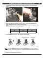
Andiron Installation
This fireplace includes four andiron brackets
that allow for use of the optional andirons.
Follow the directions below if installing
andirons. NOTE: The firebacks should be
installed prior to installing the andirons.
1
The andiron clip attaches to the front of the
burner (there are two on each side for a total
of four). Remove the screw and attach the
clip. NOTE: the firebacks are not pictured
in the pictures.
2
Secure the andiron to the clip with the bolts
included with the andirons. We recommend
you pre-thread the andirons to ease
installation.
© Travis Industries
4090102
100-01212_000
48
Index
Index
Andiron Installation .............................................47
Installation Options .............................................6
Additional Items Required ....................................7
Listing Details ....................................................2
Air Shutter Adjustment ........................................37
LP Conversion Instructions ..................................43
Altitude Considerations........................................19
Mantel Requirements ..........................................35
Approved Vent ...................................................19
Minimum Framing ..............................................11
Battery Installation..............................................16
Overview ...........................................................2
Battery Pack / Learn Switch Installation..................15
Packing List .......................................................7
Clearances ........................................................10
Power Heat Duct Installation ................................47
Dimensions .......................................................6
Preparing the Fireplace Stand-offs ........................9
Non-Combustible Facing .....................................34
Raised Fireplaces...............................................10
Facing Requirements ..........................................33
Recommended Installation Procedure....................7
Fireplace Placement Requirements .......................10
Remote Synchronization ......................................17
Framing Dimensions – .......................................12
Safety Precautions .............................................4
Gas Inlet Pressure..............................................18
Specifications ....................................................6
Gas Line Connection...........................................18
Termination Requirements ...................................30
Gas Line Requirements .......................................18
Vent Clearances.................................................20
Glass Frame Removal and Installation ..................38
Vent Installation .................................................19
Hearth Requirements – Recessed Hearth ..............32
Vent Requirements .............................................19
Hearth Requirements ..........................................31
© Travis Industries
4090102
100-01212_000