1
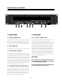
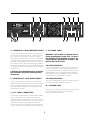
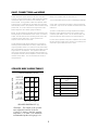
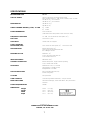
Power Amplifiers
From Fender Pro Audio
Owner's Manual for
SPL-6000
P/N 038866
OWNER'S MANUAL
SPL-6000
TWO CHANNEL POWER AMPLIFIER
SPL-6000
INTRODUCTION
Your new Fender SPL-6000 Power Amplifier is
designed to provide you with years of trouble-free
service for both permanent and portable applications. Utilizing a unique proprietary cross coupled
protection system, the SPL-6000 delivers more
power into multiple loudspeakers than more conventional approaches for VI, current limiting and
load fuses. Other features include silent delayed
turn-on and off, triac "crowbar" loudspeaker protection, full input/output connector compliment, and
a rugged "Road-Proof" 14 gauge steel chassis construction.
In order to thoroughly understand the operation,
features and functions of your power amplifier,
please read and refer, as needed, to this owner's
manual. By doing so, your amplifier is sure to provide you with years of trouble-free service.
AMPLIFIER OPERATION
This procedure applies to stereo, mono, or bridged operation into a full-range loudspeaker system which uses a passive high-level crossover (or none at all). If you are using
the SPL-6000 in a multi-amplifier system with an electronic
or low-level passive crossover, the INPUT LEVEL controls
on the amplifier are generally set to maximum (zero loss),
and all level controlling is done at the crossover (skip step
10):
9. Turn the amplifier ON.
3. Connect the wiring from the signal source(s) to the
amplifier's input jack(s).
10. Adjust the INPUT LEVEL control(s) to maximum.
Carefully advance the master control on your signal source
until the sound level from the speaker is just past the "correct" level; i.e. just a little bit too loud. Remove the input
signal from the source, leaving the master control ( and
any input controls on the source) set as they were. If the
system is noisy (hissy), reduce the setting of the INPUT
LEVEL control(s) slightly and repeat this step. You must
"juggle" the settings of the source's controls until you find
a combination that gives you the desired amplifier output,
freedom from clipping caused by excessive output
demands placed on signal source, and poor signal-tonoise performance caused by excessive amplifier gain.
4. Select the appropriate settings for the MODE switches.
WARNING:
5. Connect the speaker(s) to the output terminals, as
appropriate for the setting of the MODE switch.
- To reduce the risk of fire or shock hazzard, do not
expose this amplifier to rain or moisture.
- No user serviceable parts inside, refer
servicing to qualified personnel only.
- This amplifier must be earth grounded.
1. Turn all equipment OFF.
2. Plug the amplifier into a power source.
6. Adjust the INPUT LEVEL controls to their minimum
(infinity) setting.
7. Turn everything else ON except the amplifier.
8. Adjust the controls on the signal source for "normal"
indications on the source's meter or level indicator. If
there is no metering, then set the master control at zero
(minimum).
2
DESCRIPTION OF FEATURES
PROFESSIONAL STEREO POWER AMPLIFIER
PEAK
OFF
OFF
ON
MAX
LIMIT MIN
MAX LIMIT
MIN
LEFT •CHANNEL A
A
B
PEAK
ON
SPL 6000
POWER
ELECTRONICS
RIGHT•CHANNEL B
C
C
B
A
D
D
1. FRONT PANEL
2. REAR PANEL
A - PEAK LED INDICATOR
E & F - OUTPUT CONNECTORS
The red Peak LED Indicator illuminates when the output voltage of the amplifier reaches clipping (maximum output voltage). The threshold for the peak indicator automatically
adjusts for load impedance and supply voltage variations.
Each channel is provided with a single 1/4" phone jack (E)
and a pair of five-way binding posts (F) which will
accommodate a single pair of dual banana plugs (multiple
stacked banana plugs are not recommended as they
tend to fall out), spade lugs or bare wire. If the speaker
wire is terminated with spade lugs, make sure that the
lugs are tin or gold plated brass or copper, not plated
steel. Non-linear contact resistance phenomena will
degrade the sonic integrity of any amplifier at the speaker/amplifier interface. The Channel A and Channel B
outputs are spaced on 0.75 inch (19 mm) centers so that
one "double banana plug" can be used for bridged
operation. During performance verification measurements,
use the five-way binding posts only.
B - LIMIT SWITCHES
The Limit Switch is used to defeat the internal compressor circuits.
C - INPUT LEVEL CONTROLS
Two continuously variable attenuators control the amplifier's input sensitivity. Control settings can vary between
zero attenuation (maximum clockwise rotation) and infinite
attenuation (maximum counterclockwise rotation). At the
full clockwise rotation, a +1.8 dBV input signal is required
for rated output. Each gain control is independent except
for the Mono Bridge mode where Channel A is the active
control and the Channel B control is inactive. Refer to the
Amplifier Operation section for additional information on
proper adjustment of the input level controls.
CAUTION:
Do not operate the amplifier in the two channel
(stereo) mode with a load impedance of less than
4 Ω connected to either channel.
Do not operate the amplifier in the Bridged Mode
with a load impedance of less than 8 Ω.
D - POWER LED INDICATOR AND SWITCH
The power switch turns the unit on and off. To turn the
unit on, push the power switch to the right. The LED is
illuminated when the amplifier is turned on and main voltage is present. If this indicator does not light when the
power switch is turned on (and does not trip the circuit
breaker), then check the AC power supply.
3
TYPE: PR200
CAUTION: CHASSIS SURFACE HOT
WARNING: TO REDUCE THE RISK OF FIRE OR
ELECTRIC SHOCK, DO NOT EXPOSE THIS EQUIPMENT
TO RAIN OR MOISTURE
ATTENTION:
A PRODUCT OF:
FENDER MUSICAL
INSTRUMENTS CORP.,
CORONA, CA 91720
I
E
E
I
J
SERIAL
600 WATTS
8 OHM MINIMUM
LOAD BRIDGED
300 WATTS
4 OHM MINIMUM
300 WATTS
4 OHM MINIMUM
MONO
BRIDGE
DUAL
MONO
CAUTION:
UTILISER UN
FUSIBLE DE
RECHANGE
DE MEME
TO REDUCE
THE RISK OF
FIRE, REPLACE
FUSE WITH
L
J
M
= (+)TIP
= (–)
RING
F
K
F
1/4"
PHONE
G
FOR MONO BRIDGE
OPERTION, USE
H
K
G - MODE SELECT MONO BRIDGED/STEREO
L - AC POWER CORD
This two-position switch (left rear panel) selects either the
mono bridge or normal stereo mode. With the button in
the "in" position, the amplifier is in the mono bridged
mode. With the button in the "out" position, the amplifier
is configured for the normal two-channel stereo mode of
operation. In the Bridged Mode of operation, speaker output is taken across the two red (positive) output terminals.
The Channel A terminal is the positive output terminal and
the Channel B terminal is the negative terminal for bridged
operation only.
WARNING: This amplifier is equipped with a 3prong, grounding type supply cord. To reduce
the possibility of shock hazard, be sure to connect the unit to a grounded AC recepticle. DO
NOT ALTER THE AC PLUG!
100-120V OPERATION
This must be connected to a source of 100V or 120V, 50 to
60 Hz AC power with a current capability of at least 10 A.
As a general guideline, it is accepted to connect two (2) SPL6000 amplifiers to one (1) 20 ampere circuit provided the
load is limited to 4-ohm loudspeakers on each channel and
the signal source is full range music or speech.
CAUTION: In the Bridged Mode of operation,
the load floats and is NOT chassis ground
referenced.
H - MODE SELECT, DUAL MONO/STEREO
220-240V OPERATION
This must be connected to a source of 220-240V, 50 to 60 Hz
AC power with a current capability of at least 5 A.
This two-position switch connects the amplifier inputs
together to allow channel A and B to be summed (mixed)
for non-bridged mono operation. In the dual mono and
the stereo mode of operation, both attenuators control
their respective channels.
M - EXTERNAL FUSE
When necessary, replace the external fuse only with one of
the same type and rating as shown on the label
next to the external fuse holder.
I, J & K - INPUT CONNECTORS
Each channel is provided with a Female XLR (I) and Male
XLR (J) connectors for easy "Daisy Chain" operation
of multiple channels in large systems, and a 1/4" inch tipring-sleeve (stereo) phone jack (K). Each input is electronically balanced and will accept signals from balanced
sources (either active or transformer) or from unbalanced
circuits. Pin #2 is the positive pin on the XLR connectors.
4
BASIC CONNECTIONS and WIRING
Always use stranded wire for three reasons:
Power and audio signal cables are the most common
sources of sound system failure. Well-made and carefully
maintained cables are essential to the reliability of the
entire system. If long speaker cables are required, make
sure the wire is of sufficient size to transfer all of the available amplifier power to the speakers rather than absorbing
power itself. As a rule of thumb, the larger the wire the
better (larger wire has smaller "gauge numbers").
1) It is more flexible and less prone to metal fatigue breakage.
2) If an end is nicked while insulation is being stripped for
connection, only one or two strands will break and not the
entire wire.
3) There is some evidence, though disputed, that higher
frequency audio signals flow along the outside of each
conductor (skin effect): if this is so, the more strands, the
lower the effective cable resistance to high frequencies.
Below, we have listed the smallest wires (the highest numbered gauges) recommended for best results. To make it
simple, we'll assume you are operating under worst case
conditions with 4 ohm loads. 8 ohm operation will
improve results with the same wire.
In cases where speakers and power amplifiers are located
far away from the signal source (a mixer or a preamp), balanced line" signal cables are a wise choice.
Larger diameter (small gauge number) wire is expensive
and long cables made from it are heavy. Rather than running long speaker cables, it is better to locate power amplifiers near speakers and run a line-level signal cable over the
long distance to the amplifier. This approach eliminates
most of the signal loss due to speaker cable resistance so
the speakers are fed all of the amplifier's power without the
need for heavy cables. This can actually save money in
many instances.
SPEAKER WIRE GAGING TABLES
SPEAKER WIRE LENGTH
SPEAKER WIRE GAUGE
100'-UP
(30.5 m-UP)
50'-100'
(15.25-30.5 m)
*25'-50'
(7.60-15.25 m)
CROSS REFERENCE TABLE
10
12
12
14
14 *16
14
16
18
10'-25'
16
18
18
0'-10'
18
18
18
(3.05-7.60 m)
(0.00-3.05 m)
AWG
4Ω *8Ω 16Ω
SPEAKER IMPEDANCE [z]
*Example - The length of the speaker
wire required is between 25-50 feet
(7.60-15.25 meters) and the speaker
impedance is 8 ohms. The minimum
recommended speaker wire gauge is 16.
5
CROSS SECTION
[mm2]
18
0.83
16
1.32
14
2.10
12
3.32
10
5.27
The SPL-6000 is timed to turn on the speaker outputs
after the amplifier's power supply is fully charged up, thus
preventing any turn-on noise. Timing of the amplifier's
turn-on circuit is usually sufficient to accommodate all the
turn-on anomalies from other pieces of gear in a system,
making it acceptable to use a single switched power string
in a permanent or semi-permanent system.
CAUTION: NEVER use coiled cords for
speaker hookup, even in an emergency.
Coiled guitar-type cords usually have higher internal resistance than the speakers themselves. This is due to the
light-gauge wire used to keep the coil cords flexible.
These cords will prevent most of the power from reaching
the speakers. In high power operation, a coil cord can
melt causing a fire hazard and possible damage to the
amplifier. As a general rule, both straight and coiled guitar-type connecting cords make poor speaker cables.
CAUTION: The SPL-6000 can draw a lot of
AC power. Be sure the AC power source for
your AC distribution system has adequate
current capability.
The SPL-6000 can produce enough power output to damage electronic equipment connected to its output. Besides
being capable of destroying speakers, under certain circumstances shock and /or fire hazards are possible. High power
amplifiers should always be properly applied and used with
care in clean and dry environment.
In multiple amplifier installations, we recommend sequential turn-on (either manually or via timed relays) to avoid a
sudden major drain on the AC line.
You should keep in mind that the severe reduction of
power line voltages affects the amount of power you can
get FROM the amplifier. If you need to run long AC
extension cords, make sure their conductors are as large
as practical (small gauge number). Just as smaller diameter wire causes speaker lines loss, smaller power lines
cause loss. The effect of small AC lines is one of the
intermittent clipping under severe conditions.
If you have mounted all your sound equipment in a rack or
portable case, you can ensure that everything stays calibrated by marking the settings of the necessary controls. Small
pointers made from masking tape are visible in dim light and
can be removed with alcohol or rubber cement thinner without damage to the paint on most front panels including
those of the Fender amplifiers. Be sure to check the finish in
an inconspicuous place to determine the suitability of any
cleanser.
Assuming you are NOT turning all the equipment on at
once with a switched power receptacle "strip", be sure to
turn on the power amplifier last. This will prevent turn-on
"thumps" from the mixer or other pieces of gear that could
possibly damage speakers. The reverse logic should also
be applied -- turn OFF the amplifier FIRST -- when shutting down the system.
6
SPECIFICATIONS
DESIGNATION TYPE
PR 200
OUTPUT POWER
Stereo Continuous sine wave output power,
both channels driven +/- 1dB, 20 Hz to 20kHz, THD < 0.03%
150 W into 8 Ω, each channel
300 W into 4 Ω, each channel
MONO BRIDGE
300 W into 16 Ω
600 W into 8 Ω
SINGLE CHANNEL DRIVEN @ 1 kHz, 1% THD
8 Ω 179W
4 Ω 312W
POWER BANDWIDTH
10 Hz to 68 kHz
(3 dB down from rated power at less than 0.1% THD)
FREQUENCY RESPONSE
+0 -3dB; 5 Hz to 68 kHz (at rated power, 8 Ω)
RISE TIME
Less than 5.2 µSec
SLEW RATE
Greater than 13.5 V/µSec
TOTAL HARMONIC
DISTORTION (THD)
20 to 20 kHz at rated power, 4 Ω. Less than 0.03%
HUM AND NOISE
Below rated output, 4 Ω
20 Hz to 20 kHz broad band 95 dB
IEC A Weight 102 dB
DAMPING FACTOR
Reference, 8 Ω
5 Hz to 20 kHz Greater than 30
1 kHz Greater than 175
INPUT IMPEDANCE
Differential 33 kΩ
CHANNEL SEPARATION
Below rated power, single channel operating
1 kHz, Greater than 65 dB
SENSITIVITY
Referenced 1 kHz, +/- 0.25 dB
Stereo Mode +1.8 dBV (1.23V)
Bridged Mode +1.8 dBV
STATUS INDICATORS
Each channel-Peak LED (red)
Power LED (green)
COOLING
Two speed fan
GAIN CONTROLS
Continuously variable attenuator, one per channel
MODE SWITCHING
Stereo-Mono Bridge, Stereo-Dual Mono, two push button
switches
POWER REQUIREMENTS
1000W
DIMENSIONS
Weight
Height
Width
Depth
25 lbs.
3.5 in.
19 in.
15 in.
(11.3 kg)
(8.9 cm)
(48.3 cm)
(38 cm)
A PRODUCT OF:
FENDER MUSICAL INSTRUMENTS CORP.
CORONA, CA 91720 USA
7
THIS EQUIPMENT CONFORMS TO
THE FOLLOWING DIRECTIVES :
EMC 89/336/EEC AND LV 73/23/EEC