1
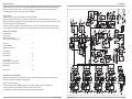
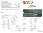
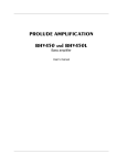
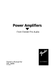
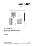
MX422
Field Mixer
PUSH
PUSH
PUSH
PUSH
12 VDC
+
-
MONITOR
INPUT
LEFT
OUTPUT
POWER
MODEL MX422
RIGHT
OUTPUT
AUX
INPUT
- 30 dB
LINE
SERIAL NUMBER
INPUT
phan
BATTERY
SELECT
low cut
4
trim
INPUT
phan
low cut
3
trim
INPUT
phan
low cut
2
trim
INPUT
phan
trim
low cut
1
NOTE: THIS MANUAL ASSUMES THE USER HAS A WORKING KNOWLEDGE OF AUDIO ELECTRONICS, BALANCED AND UNBALANCED CONNECTIONS, AND PROPER SIGNAL LEVEL
SETTINGS.
ROLLS CORPORATION
SALT LAKE CITY, UTAH
4/12
Quick Start Guide
INTRODUCTION
SCHEMATIC
Thank your for your purchase of the Rolls MX422 Field Mixer; Professional ENG mixer.
Please read and review this manual carefully as it contains important information
regarding the proper use and care of the MX422.
INSPECTION
1. Unpack and inspect the MX422 box and package.
If obvious physical damage is noticed, contact the carrier immediately to make a
damage claim. We suggest saving the shipping carton and packing materials for safely
transporting the unit in the future.
2. Please visit our website at www.rolls.com and click on the Register Your Warranty
Here button, or complete the Warranty Registration Card and return it to the factory.
TABLE OF CONTENTS
Introduction
Inspection
Table of Contents
Hearing Safety Warnings
1
Features
Specifications
Quick Start Guide
2
3
Description
Front Panel
Rear Panel
4
5
Connection
Rear Panel Connections
Front Panel Connections
Operation
6
Schematic
10
7
HEARING SAFETY WARNINGS:
While special attention has been given to your safety and hearing protection, the operator
determines proper and safe operating levels.
Please note the following:
- Always turn down the PHONES level control before plugging in your headphones.
- Always operate your headphones at the lowest practical level.
- Be especially cautious in unknown or widely varying environments.
1
www.rolls.com
www.rolls.com
10
FEATURES
HEADPHONE/EARPHONE MONITORING
PLEASE NOTE: The MX422 has very loud headphone and earphone circuitry. Be sure
to turn down the Phones level control before selecting the Source and putting your
headphones or earphones on to prevent accidental hearing damage.
HEADPHONE/EARPHONE SOURCE SELECT
When monitoring for recording, you typically will listen to the signal from the Main
Outputs. Leave the SOURCE button in the out position to monitor the Main Output
signal.
Occasionally, you’ll need to listen to an alternate signal - i.e. a remote truck or recording engineer. Their signal is generally connected to the Monitor Input jack. Press in the
SOURCE button to listen to the signal on the Monitor Input.
OUTPUTS
The MX422 is a two-bus mixer with two individual balanced male XLR output jacks.
Each output is isolated providing excellent signal connectivity and noise performance.
These outputs are generally connected to a recording device or other input looking for
a line-level signal. In the event you need to connect the MX422 output to a mixer’s Microphone Input, press in the Output Level select switch to -30 dB. This way the MX422
output is attenuated by 30 dB, and will be more compatible with an input looking for a
microphone level signal.
MASTER LEVEL CONTROL
The front panel Master Level control adjusts the overall output level of the Left and
Right outputs. The gain range of the Master Level is from complete attenuation (no
output signal) to +12 dB of gain. Ideally, the Master Level should be set as close to the
detent as possible, providing you with the maximum amount of variance and headroom.
POWERING
The MX422 features a unique and useful battery scheme. Two separate battery compartments have been provided on each side of the unit. In the event of battery voltage
loss during recording, the rear panel BATTERY SELECT switch may be moved to the
other position to select the second set of batteries. This is achieved without any signal
loss!
We recommend using 9V alkaline type batteries, however Lithium or NiMH batteries
work as well. To check the status of the selected battery set, press and hold the front
panel BATT TEST button.
For AC power, Rolls provides the model # PS27s VDC supply to power the MX422.
9
www.rolls.com
- Four servo-balanced XLR Inputs
- Two transformer-balanced XLR Outputs
- Switchable Output Level ( Line level, or -30 dB pad)
- 1/4” TRS Stereo Monitor Input and Auxiliary Input
- Switchable 48 Volt Phantom Power for each input
- Switchable 100 Hz Low Cut filters for each input
- Two sets of battery compartments, never lose power
- Level and Pan controls for each channel
- Built in Limiter with variable Threshold control
- 20 Hz Slate tone with Slate Microphone included
- Switchable 1 kHz setup Tone
- Calibrated VU meters
- 1/4” and 1/8” (3.5mm) Headphone/Earphone Outputs with selectable Source
Input (Main mix buss or Monitor input),and Level control
- Canvas case included
- 6 hour battery life (with 2 condenser mics using phantom power and head
phones attached, constant use).
- Rolls PS27 external power supply included
SPECIFICATIONS
Input Impedance:
Mic:
Source:
10K Ohms XLR balanced
22K Ohms RCA
Limiter Threshold:
-5 dB to off
fully clockwise: No Limiting
Setup Frequency:
1 kHz
Slate Frequency:
20 Hz
Output Attenuator:
-30 dB
Self Noise:
-57 dB maximum
-90 dB typical
Max Gain:
+65 db
S/N Ratio:
115 dB
THD:
.05%
Frequency Response:
20 Hz - 30 kHz | +0, -3 dB
Low Cut:
100 Hz
Trim Range:
0 to + 38 dB
Max Input:
0 dBV
Current Draw:
45 mA with no Phantom Power or Signal.
Phantom Power:
+48 VDC
Typical Batery Life:
6 Hrs. (2 mics, phan on, 1 headphone)
Connectors:
4 ea. Female XLR, 2 ea. Male XLR, 3 ea. 1/4”,
1 ea. 1/8” (3.5mm), 1 Center Negative power jack.
Power:
Size:
Weight:
VDC / 200 mA min.
9.5” W x 7.25” D x 2.375” H
4 lbs
www.rolls.com
2
QUICK START GUIDE
For those familiar with ENG or field mixers, this guide highlights basic functionality to begin
operating your MX422.
POWERING
To power the MX422 and get it ready for operation:
1. Insert four 9-Volt alkaline batteries into the battery compartments. Insert with the correct
polarity. NOTE: Only one pair of batteries is being used at a time. The other pair is a backup. More
on that later.
2. Or, connect external DC power (the Rolls PS27s) VDC to the MX422 DC Input connector.
3. Press in the POWER button.
4. Check battery life by pressing the BATT button.
INPUT CHANNEL SETUP
To set up a gain level for an input channel:
1. Connect a signal source (microphone or line level signal) to a channel input connector.
2. Set the rear panel trim control at the 12 O’clock position (this is just a starting point).
3. If you’re using a condenser microphone, activate the Phantom Power by pressing in
the phan button.
4. Set the LEVEL Control at the 12 O’clock position (again - just a starting point).
5. Set the channel PAN control for the desired signal position in the stereo field.
6. Press in the rear panel “low cut” switch if needed.
7. Verify there is signal present on the output meter(s).
OUTPUT CONNECTION
To connect to the MX422 main Outputs
1. Connect an XLR cable to the LEFT and RIGHT Outputs of the MX422.
2. Set the output level switch to either LINE (switch out), or -30 dB (switch in).
3. Verify that the next device in the signal chain is receiving signal from the MX422.
HEADPHONE MONITORING
1. Connect stereo headphones or earphones to the HEADPHONE outputs on the front panel.
NOTE: THESE MUST BE STEREO HEADPHONES OR EARPHONES - USING MONO PHONES WILL
DAMAGE THE MX422.
2. Select the Phones signal SOURCE (monitor either the Main signal; switch out, or Monitor
Input; switch in).
3. Set the PHONES level to 0.
4. Verify signal in the phones by slowly bringing up the PHONES level control.
5. Set the PHONES level control for a comfortable level.
METERING
1. View the Main RIGHT and LEFT output signal levels on the ref. +4 dB VU meters.
2. To check the available battery voltage - press the BATT TEST button.
PAN CONTROL
The Pan control routes an input channel signal anywhere between the Left and Right
outputs. The MX422 uses constant loudness pan controls, meaning that the signal is 3
dB louder at the full right or full left position relative to the center position. Usually, the
channel is either panned full left, full right, or center.
The pan potentiometer has a detent in the center position for easy location, and it is
calibrated for a maximum difference of +/- 0.1 dB between the left and right output in
this position.
LIMITER
The MX422 Limiter acts as a ”safety” limiter. During normal operation, with a properly
set gain structure, the threshold of the limiter will not be reached. If extremely high input signal levels exist, such as in high SPL environments or with misadjusted settings,
the limiter will activate to prevent the channel from clipping. Without a limiter, high
signal conditions would overload the channel and cause distortion.
Adjust the LIMITER THRESH control to a point above your normal operating levels, but
safely below levels causing distortion or “pegging” of the VU meters.
METERING
The MX422 features two calibrated, backlit VU meters. VU (Volume Units) meter ballistics correspond closely to how the human ear perceives loudness and provides a good
visual indication of how loud a signal will be. The attack and decay of the meter signal
is 300 mS. The indicated level on the meters is referenced to +4 dB.
SLATE TONE AND MICROPHONE
The Slate Tone and Microphone circuit is used to notate scenes at the mixer location.
The Slate circuit uses the front panel momentary button. When this button is pressed,
a 20Hz tone is sent to the Main Outputs, and the Slate Microphone becomes active.
When notating a scene - press and hold the Slate button, speak into the four-holed
Slate microphone, and release.
1kHz TONE
This oscillator is provided to set the gain structure between the MX422 and the next
device in your signal chain. The Tone oscillator is set to output a 1 kHz sine wave to
the Main Right and Left outputs (with the Output Level switch set in the out or LINE
position). Note this tone is also sent to the Headphone outputs when the Headphone
SOURCE button is in the MAIN position. It would be a good idea to remove your headphones or earphones when the Tone button is pressed in. When levels are set, press
the Tone button again to disengage the Tone oscillator.
LIMITING
1. For no limiting at all, turn the LIMITER THRESH control completely clockwise.
2. To set a limiting point, send signal through the MX422 and slowly turn the LIMITER THRESH
control counter-clockwise until the desired amount of limiting is acheived.
3
www.rolls.com
www.rolls.com
8
OPERATION
DESCRIPTION
INPUT CHANNELS
The inputs to the MX422 consist of four, full-featured microphone preamplifiers.
Each channel has a wide gain range to accommodate nearly all signal types. The unit
accepts signals ranging from low-sensitivity ribbon and dynamic microphones to medium level wireless and condenser mic outputs, up to the “hot” line levels.
The MX422 input channels can be used as wither balanced or unbalanced connections. When unbalancing - ground pin-3 to pin-1. There is no change in gain between
unbalanced and balanced connections into the MX422.
The AUX INPUT jack is provided for recording stereo sources such as CD players, MP3,
players, DVD, etc.
FRONT PANEL
LEVEL 1, 2, 3, and 4: Adjust the level of signal from the corresponding Mic Input.
TRIM CONTROL
Like traditional mixing consoles, the MX422 microphone preamp gains are set via the
trim control. This control adjusts the input sensitivity of the channel input so that the
channel fader can be set to operate in a usable range. Once set, the trim is typically
kept at the set level and all mixing is done on the channel front panel Level control.
PAN 1, 2, 3, and 4: Adjusts the relative Right/Left signal level to the mix bus.
INDIVIDUAL CHANNEL LEVEL CONTROLS
While both the trim and channel Level controls adjust the gain of a given channel, the
Level is the primary channel volume control. The trim can be thought of as a “course”
gain adjustment to be adjusted during setup, and the Level control is a “fine” gain
adjustment used while recording. With a properly set up trim control, the Level can be
set to a nominal level (around 12 O’clock) providing the maximum amount of variance
and headroom.
COMP THRESH: Sets the level at which the compressor will “compress” or lower the
PHANTOM POWERING
The MX422 can provide up to 10 mA of current to each input at 48 Volts, sufficient for
the most power-hungry condenser microphones. The MX422 Phantom Power utilizes
a fixed 48 Volts DC which is resistively applied to pin-2 and pin-3 of an XLR input connector relative to pin-1 (there is no voltage difference between the signal on pins -2
and - 3; a dynamic microphone may or may not operate normally in the presence of
phantom power).
It is generally a good practice to turn off phantom powering when not using a condenser microphone as it can capacitively couple noise into the mic inputs with poor
mic cables. Also, be sure to turn off phantom powering when using ribbon microphones since an improperly wired cable can permanently damage the microphone.
LOW-CUT FILTERS
Each channel of the MX422 features a switchable Low-Cut filter set at 100Hz. These
Low-Cut (sometimes called “High Pass”) filters are useful for removing excess low
frequency energy in audio signals. Wind noise is a common unwanted low frequency
signal and a low-cut filter is effective for reducing wind noise. For several audio applications engaging the Low-Cut filter is beneficial since little usable audio information
exists below 100 Hz - especially for speech recording.
7
www.rolls.com
SLATE MIC: When the Slate Button is pressed and held in, the sound at this microphone
is sent to the main outputs, along with a 20Hz sine wave signal.
SLATE BUTTON: Engages the Slate Mic.
signal level.
1 kHz TONE: When pressed, this button sends a 1 kHz signal to the main outputs.
BATT TEST: When pressed, this button will indicate the approximate battery voltage on
the VU meters. Proper battery voltage will be indicated with the meters moving to the
red region of the field. If the meters are below the red region, battery replacement is
necessary.
HEADPHONE LEVEL: Adjusts the level of signal from the Headphone Outputs.
HEADPHONE SOURCE SELECT SWITCH: When this button is OUT, the sound heard at
the Headphone Outputs will be that of the Main Output, when it is pressed IN, the
sound heard will be that of the Monitor Input.
HEADPHONE/EARPHONE OUTPUTS: 1/4” Tip-Ring-Sleeve and 1/8” (3.5 mm) TipRing-Sleeve jacks containing either the Main Output signal or Monitor Output signal
depending on the setting of the Headphone Source Select Switch.
www.rolls.com
4
DESCRIPTION CONT.
REAR PANEL
PUSH
PUSH
PUSH
PUSH
12 VDC
+
-
MONITOR
INPUT
LEFT
OUTPUT
POWER
MODEL MX422
RIGHT
OUTPUT
AUX
INPUT
- 30 dB
LINE
SERIAL NUMBER
INPUT
phan
BATTERY
SELECT
low cut
4
trim
INPUT
phan
low cut
3
trim
INPUT
phan
trim
low cut
2
INPUT
phan
trim
low cut
1
VDC : Power input connector. Connects to the optional Rolls PS27s Power Adapter.
POWER: Button - turns the MX422 on and off.
MONITOR INPUT: 1/4” Tip-Ring-Sleeve jack for connection to a stereo signal source to
CONNECTION
REAR PANEL CONNECTIONS
Connect your microphones
to the MX422 using balanced
XLR cables. Connect the
MX422 Outputs to the next
device in your signal chain
(usually a recording device of
some kind), also via balanced
XLR cables.
For monitoring external signal
sources, connect a stereo
(Tip-Ring-Sleeve) plug to the
Monitor Input
be monitored. This signal connects directly to the Phone Level control, and the Headphone Outputs.
LEFT/RIGHT OUTPUT: Balanced XLR jacks containing the main mix signal. Pin 2 is configured ”hot”, pin 3 is neutral, and pin 1 is conntected to chassis ground.
OUTPUT LEVEL (-30 dB / LINE): When pressed in, this button pads the Output signal by
30 dB.
FRONT PANEL CONNECTIONS
BATTERY SELECT: This switch selects which set of battery compartments are being
Connect your headphones or earphones to the MX422 front panel as shown below.
used. When the switch is to the left, the left side (with the back panel facing you)
battery compatments are being used. When the switch is to the right, the right side
IMPORTANT NOTICE: DO NOT PLUG MONO (Tip-Sleeve) PLUGS
INTO EITHER PHONES JACK. DOING SO WILL DAMAGE THE MX422.
battery compartments are being used.
Carefully adjust the Phones Level control for a comfortable listening level.
AUX INPUT: 1/4” Tip-Ring-Sleeve jack for connection to an auxiliary line-level stereo
signal such as the output of another mixer, AM/FM tuner, CD player, etc.
INPUTS 1 - 4: Balanced XLR jacks for connection to dynamic or condenser microphones
- or, to a balanced line-level signal.
TRIM: Adjusts the input signal gain to the corresponding channel.
PHAN 1 - 4: When pressed in, this button applies 48 volts of phantom power to the corresponding Input.
LOW CUT 1 - 4: When pressed in, this button reduces the low frequency (100Hz and
below) of the corresponding Input signal.
5
www.rolls.com
www.rolls.com
6