1
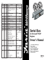
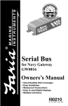
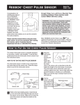
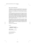
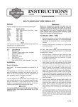
Table1
Connector
Contacts
P1
2
P2
4
Pin
PIn Function
Wire Color
Not used
1
3
4
Red
Purple
Faria® Bus Data and
Instrument Power
N/A
(HN0516)
Black
4
P4
2
Not Used
(PJ0015)
P5
3
Not Used
(PJ0016)
P6
3
Evinrude Engine ECU
N/A
(HN0504)
P7
3
Evinrude Engine Diagnostic Port
N/A
(HN0501)
P8
PP
Not Used
P9
PP
Not Used
P10
PP
Engine Water Pressure
P11
12
Not Used
P12
12
P14
P15
2
6
8
(HN0502)
Pressure Hose
(HN0514)
3
5
Ground (Sensor)
Sensor Power
Black
(HN0523)
Purple/White Stripe
6
Fuel Flow Sensor
White
7
Ground (Sensor)
Black
10
Speedometer -Paddle wheel
signal (AirMar Sender)
Green
12
Navigation Lights
Dk. Blue
1
Depth Sounder Transducer
signal (AirMar Transducer)
Blue
2
Depth Sounder Transducer
Ground (AirMar Transducer)
Black
1
Fuel Tank Sender
Pink
2
Trim
White/Tan Stripe
3
Oil Level
Pink/Yellow Stripe
3
SystemCheck Tachometer input
Gray
4
5
No Oil
Low Oil
Tan/Yellow
Gray/Black
6
Over Temperature
Tan
7
Check Engine
Tan/Orange
*5 amp Fuse Recommended
Mode
Mode
P3
P13
All
Battery Positive (always on)*
Switched Power from Ignition
switch circuit
Ground
(HN0505)
(HN0524)
Serial Bus
for Evinrude® FICHT
Engines
Owner’s Manual
Visual /Audible Alert Messages
Easy Installation
Waterproof Connections
Easy to Read Digital Displays
Easy to use Depth Sounder
Easy to use Fuel Management
Multiple Interfaces
IS0150
ECR#2141 02/04/02
Page 15
Faria Serial Bus Gateway
Table of Contents
Initial Setup
Trim Calibration
Speedometer selection
Operation
General
Speedometer/Depth Sounder
Depth Sounder
Shallow Alarm
Deep Alarm
Keel Offset
Units
Speedometer Calibration
Tachometer/Fuel Management/Hourmeter/ SystemCheck®
Fuel Management
Instantaneous Fuel Consumption
Trip Fuel Consumed
Fuel Remaining
Fuel Remaining Alarm Setting
Engine Hourmeter
SystemCheck®
SystemCheck Error Codes
Installation/Harness wiring guide for Evinrude® Engines
Gateway
Gateway Harness connections
Figure 1 Typical Power Connections
Figure 2 Typical Instrument Connections
Figure 3 Evinrude Engine ECU Connection
Figure 4 Airmar® Tri-ducer Connections
Figure 5 Miscellaneous Connections
Figure 6 Fuel Flow and SystemCheck Connections
Figure 7 Water Pressure Connection
Figure 8 Diagnostic Port Connection
Wire Harness/Connections Table
Water Pressure Connection
Page 2
Page 2
Page 3
P13
P9
P12
P15
P7
P1
P10
P8
P6
P3
P2
Water Pressure
Fitting on the
Evinrude Engine
Figure 7
Diagnostic Port Connection
P13
Page 10
P9
P12
P15
Page 11
Page 11
Page 12
Page 12
Page 13
Page 13
Page 14
Page 14
Page 15
P4
P11
P14
Page 3
Page 3
Page 4
Page 4
Page 4
Page 4
Page 5
Page 5
Page 6
Page 7
Page 7
Page 8
Page 8
Page 9
P5
P14
P7
P5
P4
P1
P3
P2
P11
P10
P8
To use the Evinrude diagnostic test equipment, you
must remove the “Jumper Plug” from P7 and then
connect the diagnostic unit at P7.
With the diagnostic unit plugged in, the system is
now in the Diagnostic Mode. Normal diagnostic
procedures should be followed.
P6
Evinrude
Diagnostic
Computer
Note: Instruments are disabled in the Diagnostic
Mode. To return to normal operation, replace the
“Jumper Plug in P7. Turn off power to the
“Gateway.” Reapply power. Serial Bus system is
now in Normal Operation mode.
Evinrude, SystemCheck, and FICHT are trademarks of Bombardier Motor Corporation
Figure 8
Page14
Faria Serial Bus Gateway
System
Miscellaneous Connections
P13
P15
P14
P9
P12
P7
P5
P4
P1
P3
P2
P11
P10
1 2 3
P8
P6
Pink
Pink/Yellow
White/Tan
HN0524
Oil
Level
Sender
Trim
Sender
Fuel
Level
Sender
Figure 5
The system consists of:
• One Gateway box to interface with
Evinrude ECM and external senders
and sensors.
• One 4” Tachometer with Fuel
Monitor
• One 4” Speedometer with Depth
Sounder
• Various 2” instruments, including but
not limited to
• Voltmeter
• Oil Level gauge
• Engine Temperature gauge
• Fuel Level gauge
• Trim gauge
• Engine Water Pressure gauge
• others as specified.
engine is at it’s lowest point to store the
value. The display will change to “TRIM”
and an up arrow, “ ”. Trim the engine to
its highest level. Press the up button when
Up
Button
the engine is at it’s highest point to store
the value. The display will go back to
“TRIM” and a down arrow, “ ”. The trim
calibration is now complete. To go to
speedometer selection, press the “modeM” button for less than 1 second.
To exit initial set-up, press and hold the
“mode-M” button for more than 1 second.
The trim calibration can be repeated if
desired.
M
Fuel Flow and SystemCheck® Connections
P13
P15
P14
P9
P12
5
6
7
Black White
P7
Initial Setup
P5
P4
P1
P3
P2
P11
P10
P8
P6
The speedometer is used to initialize the
parameters for each serial bus installation.
Holding the “mode-M” button down while
turning on power will allow access to
these parameters. Pressing and releasing
the “mode-M” button will select one of the
following options:
Purple/White
M
Mode
Button
HN0523
Fuel Flow Transducer
SystemCheck
Connector
Figure 6
Page 13
Black
White
Shield w/Heat Shrink
1. Trim calibration. The display will show
“TRIM” and a down arrow, “ ”. Using the
trim control, set the motor to the lowest
position. Press the “Down” button when
the
Down
Button
Mode
Button
2. Speedometer selection. Pressing and
releasing the “Up” button or the “Down”
button
Up
Button
Down
Button
will change the display to select one of two
speedometers:
• 70 MPH (default)
• 50 MPH
To go back to trim calibration, press the
“mode-M” button for less than 1 second.
To exit initial set-up, press and hold the
“mode-M” button for more than 1 second.
M
Mode
Button
Page 2
Faria Serial Bus Description
Operation
General
The Faria Serial Bus system is designed to
receive information from the engine EMM
and various individual sensors throughout
the boat. This information is transformed
into digital data which is distributed to
analog and digital instruments via a single
cable consisting of two shielded twisted
pairs of conductors. Each instrument
selects the data which is applicable and
displays it as if it was being received from
the sender directly. One of the two pairs of
conductors carries the data while the other
pair of conductors carry the power for the
instruments.
The four-inch serial bus instruments have
three push buttons which allow the
different functions of each instrument to
be activated. Following is a description of
these functions.
Speedometer / Depth Sounder
The Serial Bus Speedometer / Depth
Sounder provides the functions of a
speedometer, a depth sounder and a
speedometer calibration feature. The
analog speedometer is a stepper motor
instrument which looks like a standard
analog device but which is actually a
digital instrument. On small pointer
movements you may occasionally see the
pointer moving in the one-third degree
“steps” that represent the accuracy of the
instrument.
To turn the depth sounder on, the ignition
key must be in the ‘run’ position. Press the
“mode-M” button to turn on the depth
sounder.
M
Mode
Button
Turning off the ignition key will turn off
the depth sounder.
Page 3
The LCD screen displays the data for the
remainder of the functions. If there are no
alarm conditions, the water depth is
displayed on start-up.
Faria Serial Bus Gateway
Evinrude Engine ECU Connection
Depth Sounder
P13
In normal operation the LCD will show
the current depth. If there is no transducer
connected or the signal is weak then the
display will alternate between the last
known depth and three vertical bars.
Pressing the “mode-M” key quickly while
M
P12
P15
Depth Sounder Settings
To change the depth sounder alarm
settings, the “mode-M” button must be
held down until the display changes to the
P10
P8
P5
P6
Evinrude
Engine ECU
P4
P1
P3
P2
HN0504
Figure 3
Airmar® Tri-ducer Connections
HN0505
Blue
Blue
Black
Black
Mode
Button
P13
alarm mode. There are four menus in the
alarm mode. Quickly press the “mode-M”
switch to cycle through the different
options.
10
P9
3
P12
P15
P14
P7
5
P10
P8
P6
Black
P4
P1
P3
P2
Paddle Wheel Sender
White & Bare
The display will show “S X.X ” which is
the current setting for the shallow alarm.
Pressing the “Up” or ”Down” buttons will
change the shallow setting.
P5
P11
Purple/
White
Shallow alarm - Alarm sounds when water
depth equals or is less than set value.
Red
Green
HN0523
Down
Button
P7
P11
P14
Mode
Button
in depth sounder normal operation
displays the speedometer calibration mode.
This is described in a later section.
M
P9
Black
Blue
Green
Brown
Note: Tri-ducer connections
shown. Brown wire is not
used, leave unconnected.
Up
Button
Figure 4
Page12
Faria Serial Bus Gateway
Press and hold the “mode-M” button in for
1 second to save the new shallow setting
and change the display back to the normal
depth mode. To disable the alarm, set the
reading to “S 0.0”.
Typical Power Connections
P13
P9
P12
P15
P7
P5
P4
P1
M
P11
P14
P10
P8
P6
P3
P2
Deep alarm - Alarm sounds when water
depth equals or is greater than set value.
Black
Red
Key
Switched
Power
+
Mode
Button
The display will show “d XX.X”, which is
the current setting for the deep alarm.
Pressing the “Up“ or “Down” buttons will
Purple
HN0516
Battery
Up
Button
Down
Button
Figure 1
change the deep setting. Press and hold the
“mode-M” button in for 1 second to save
the new deep setting and change the
display back to the normal depth mode. To
disable the alarm, set the reading to
“d 0.0”.
Typical Instrument Connections
HN0503
HN0503
HN0503
M
Mode
Button
Keel offset - Adjust depth sounder to
measure depth below keel instead of sensor.
PJ0018
HN0502
Note: To help reduce moisture
in the gauges be sure to install
plug PJ0018 in all open connectors.
P13
P14
Figure 2
Page 11
P9
P12
P15
P7
P5
P4
P1
P3
P2
P11
P10
P8
P6
The display will show “K X.X” which is
the current setting for the keel offset.
Pressing the “Up” or “Down” buttons will
change the keel offset setting. Press and
hold the “mode-M” button in for 1 second
to save the new keel offset setting and
change the display back to depth display
mode. To disable the function, set the offset
to “K 0.0”.
Down
Button
Up
Button
M
Mode
Button
If a keel offset is entered, all depth
soundings will subtract the offset from the
sensor measured value. The display will
show the depth of water below the keel,
not the surface. Likewise, the shallow and
deep alarms will automatically be
measured from the keel, not the surface.
Units - Change the unit of measure.
The display will show “UNIT FT” for feet,
“UNIT FA” for fathoms, or “UNIT M” for
meters. Pressing the “Up” or “Down”
buttons will cycle through the choices.
Up
Button
Down
Button
Pressing and holding the “mode-M” button
will save the units shown in the display
and change the display back to the normal
depth mode. The default units are “feet”.
M
Mode
Button
Speedometer Calibration
The analog speedometer displays the
speed of the boat through water. The
speedometer is calibrated at the factory for
normal installations which use a Faria
paddle wheel sensor. As significant
variation has been found in paddle wheel
installations, the speedometer can be easily
field calibrated to a known reference such
as a radar gun or GPS. When the unit is
operating in normal mode (i.e. depth
sounder), a quick push on the “mode-M”
button will cause the speedometer to go
Page 4
M
Mode
Button
into the calibration mode. The LCD will
show “CAL “.
When the “Up” button is
Up
Button
pushed, the speedometer pointer will
move upscale.
When the “Down” button is pushed, the
Down
Button
speedometer pointer will move down
scale. When the speedometer reads the
same as the reference, release the button.
This process can be repeated as necessary
to ensure correct calibration. Press and
hold the “mode-M” button in to save the
M
Mode
Button
calibration setting and return to the depth
sounder. Release the “mode-M” button
when the depth is displayed.
Tachometer / Fuel Management /
Hourmeter / SystemCheck
The Serial Bus Tachometer/Fuel
Management unit provides six functions,
five of which can be accessed through the
normal running display.
Page 5
The remaining function, which is “Total
Fuel Consumed”, is provided to allow
monitoring fuel usage over a longer period
of time, such as fuel used for the month or
the season. In order to prevent inadvertent
reset, this function must be accessed using
a special “power on mode”.
The analog Tachometer is a stepper motor
instrument which looks like a standard
analog device but which is actually a
digital instrument. On small pointer
movements you may occasionally see the
pointer moving in the one-third degree
“steps” that represent the accuracy of the
instrument.
The LCD screen displays the data for the
remainder of the functions. If there are no
alarm conditions, “Instantaneous Fuel
Consumption” is displayed on start-up. A
short press of the “mode-M” button
advances the display through the five
normally available functions.
Faria Serial Bus Installation and Wiring Guide (Evinrude® Engines)
The system consists of:
• One Gateway box to interface with Evinrude ECM and external senders and sensors.
• One 4” Tachometer with Fuel Monitor
• One 4” Speedometer with Depth Sounder
• Various 2” instruments, including but not limited to
• Voltmeter
• Oil Level gauge
• Engine Temperature gauge
• Fuel Level gauge
• Trim gauge
• Engine Water Pressure gauge
• others as specified.
Installation
Installation of the Faria Serial Bus system is accomplished as follows:
Gateway Box
The “gateway” box is the central unit of the system. As all of the senders and other
information source peripherals connect to the “gateway”, the “gateway” box should be
mounted in a protected area in the best location to provide the maximum cabling
benefit.
When in normal display mode, the
instrument lights are turned on and off
with the navigation lights. Intensity is
controlled by the “Up” button. Pressing the
“Up” button will cycle the instrument
lights through three levels of intensity.
The “gateway” box power cable must be installed to allow connection to “battery
positive” (always on), “battery negative” (ground), and a source of “switched power”
which turns on with the engine ignition switch (see Figure 1 and Table 1).
Fuel Management
The remainder of the connections to the “gateway” box are described below.
The “Faria Bus” cable must be routed from the “gateway” box to the instrument panel
area to connect the instruments to the data bus and instrument power (see Figure 2).
There are four functions displayed by the
Fuel Management system in normal mode.
Instruments
Instantaneous Fuel Consumption
Displays the actual amount of fuel being
consumed per hour under the current
operating conditions. Default display will
show “G/H XX.X”.
The instruments are mounted using the provided back-clamps and mounting hardware.
Each instrument comes with a bus connection cable (12”). The main “Faria Bus” cable
from the “gateway” box is connected to the most convenient instrument using either of
the two four (4) pin connectors provided on the instrument case (*except when a Faria
Serial Bus Pilot or a Faria Speedometer-PerfectPass Cruise instrument is installed, see
note below).
Pressing the “mode-M” for more than one
second will allow selecting the units of
measure. Default display will show
“G/H XX.X”. A short press of the “mode-M”
M
Mode
Button
Each additional instrument is connected to the previous instrument using one of the
12” bus connection cables. The cable may be connected to either of the two connectors
provided on the instrument case (see Figure 2).
*NOTE: The Faria Serial Bus Pilot and the Faria Speedometer-PerfectPass Cruise instruments are
“end of the bus” instruments. Only the provided four (4) pin connector is to be connected to
the “Faria Bus”. See special instructions for use of the six (6) pin connector on these
instruments.
Page 10
SystemCheck® Error Codes
CODE
12
13
14
15
16
17
18
22
23
24
25
26
27
28
29
31
34
35
37
38
39
45
46
48
49
51
52
53
54
55
56
57
81
82
83
84
85
86
DESCRIPTION
See Dealer - code 12
Throttle cable adjustment at idle - code 13
Throttle cable adjustment at WOT - code 14
EMM problem - See dealer - code 15
Crank sensor problem - See dealer - code 16
Low injector voltage - code 17
High injector voltage - code 18
Engine overheat - See owner’s manual - code 22
See Dealer – code 23
See Dealer - code 24
ECU/EMM overheat - code 25
Low battery voltage
High battery voltage
Shift assist problem – See dealer code 28
Engine shutdown – ECU temp – See dealer – code 29
Engine shutdown - Eng temp – See dealer – code 31
Oil system problem - See dealer immediately - code 34
Oil pressure loss - See dealer immediately - code 35
Water in fuel - See owners manual - code 37
No oil feedback – See dealer – code 38
Oil prime failure – See dealer – code 39
See Dealer - code 45
See Dealer - code 46
Low air temp - code 48
High air temp - code 49
#1 Fuel injector problem - See dealer - code 51
#2 Fuel injector problem - See dealer - code 52
#3 Fuel injector problem - See dealer - code 53
#4 Fuel injector problem - See dealer - code 54
#5 Fuel injector problem - See dealer - code 55
#6 Fuel injector problem - See dealer - code 56
Engine Malfunction - Do not restart engine – Seek
assistance to return to port – code 57
#1 Ignition coil problem - See dealer - code 81
#2 Ignition coil problem - See dealer - code 82
#3 Ignition coil problem - See dealer - code 83
#4 Ignition coil problem - See dealer - code 84
#5 Ignition coil problem - See dealer - code 85
#6 Ignition coil problem - See dealer - code 86
Other SystemCheck messages
Low oil level – Add oil to the oil tank
Page 9
button advances the display through the
options. Options are:
a) US gallon units. Display will show
“US GAL”, display - “G/H XX.X”.
b) Imperial gallons units. Display will show
“IMP GAL”, display - “I/H XX.X”.
c) Liters. Display will show
“LITERS”, display – “L/H XX.X”.
Leaving the display in one of the items
above while the “mode-M” button is
pressed and held for more than one second
will save the selected units.
M
Mode
Button
Trip Fuel Consumed
Displays the amount of fuel consumed
since last reset. Can be reset to zero prior
to a trip to show fuel consumed during the
trip. Display will show “TRPXXX.X”.
Pressing the “mode-M” for more than one
second will access the options that are
available for this function.
M
Mode
Button
A short press of the “mode-M” button
advances the display through the options.
Display will show “TRPXXX.X”. Options
are:
M
Mode
Button
a) Clear Trip Fuel Consumed. Display
will show “CLR TRP”. Pressing the modeM button for more than one second while
the display shows “CLR TRP” will clear
the trip amount and set the menu back to
the Trip Fuel Consumed function. A quick
press of the “mode-M” button will skip
this feature.
b) Adjust Trip Fuel Consumed, (fuel flow
calibration). Display will show “ADJ TRP”.
Pressing the “mode-M” button for more
than one second will cause the display to
go into the Trip Fuel Consumed adjustment
menu.
Mode
Button
M
The display will show “ADJXXX.X”.
Pressing and holding the “Up” button will
Up
Button
increase the amount and pressing and
holding the “Down” button will decrease
the amount.
Down
Button
Holding the “mode-M” for more than one
second while the display is showing
“ADJXXX.X” will set the amount in the
display “XXX.X” into the Trip Fuel
Consumed and return to the Trip Fuel
Consumed function. The difference between
the original and the new amount of fuel will
be used to change the calibration of the
instant and accumulated fuel data.
This feature allows the fuel flow system to
be calibrated by accurately filling the fuel
tank at the beginning and end of a trip.
When the tank is refilled at the end of the
trip, record the exact amount of fuel placed
in the tank. Using the above procedure,
adjust the amount of fuel shown in the
“ADJ TRP” to match the amount of fuel
recorded. Save the corrected amount as
described above. The Trip Fuel Consumed
in the previous menu can then be cleared
Page 6
for re-use or left to continue to accumulate
fuel usage.
Fuel Remaining
Displays the fuel remaining based on a
manually entered amount of fuel minus
the amount of “Trip Fuel Consumed”.
Display shows “REMXXX.X”. This
reading is independent of the fuel “gauge”
reading.
In normal use the amount of fuel in the
fuel tank is adjusted manually (see below)
when the fuel tank is filled so that this
display shows the total amount of fuel in
the tank. The Trip Fuel Consumed is then
reset to zero. As fuel is used (displayed in
the Trip Fuel Consumed) this display will
show the decreasing amount of fuel
remaining.
Pressing the “mode-M” for more than one
second will access the option available for
this function.
M
Mode
Button
a) Add to or remove gallons from the Fuel
Remaining. Display shows “R+-XXX.X”.
Holding the “Up” button will increase the
menu to fuel remaining.
This feature allows the operator to
accurately set the amount of fuel in the
fuel tank when adding fuel. The accuracy
of this manually entered value directly
affects the Fuel Remaining and Fuel
Remaining Alarm functions, and should be
done carefully.
Fuel Remaining Alarm Setting
Displays the setting for the “Low Fuel”
alarm. The display shows “ALRXXX.X”.
When the “Fuel Remaining” reaches this
amount, the “Low Fuel” alarm will sound
and a warning LED will flash in the
display. The display will automatically go
into “set” mode to allow the operator to
reset the alarm value to a lower value to
turn off the alarm if desired. If the option
is set to zero, the “Low Fuel” alarm will be
disabled.
Pressing the “mode-M” for more than one
second will access the option available for
this function.
M
Mode
Button
a) Set the amount of fuel remaining when
the alarm will go off. The display shows
“A+-XXX.X”. Holding the “Up” button
Up
Button
Up
Button
amount and holding the “Down” button
will increase the amount and holding the
“Down” button will decrease the amount.
Down
Button
will decrease the amount. Holding the
“mode-M” button for more that one
second will set the remaining fuel to the
value shown in the display and return the
Page 7
Down
Button
Holding the “mode-M” button for more
that one second will set the fuel alarm to the
value shown in the display and return the
menu to the Fuel Remaining Alarm Setting
function.
Engine Hourmeter
Displays the number of hours that the
engine has been operated. The display will
show “XXXXX.XH”.
There are no adjustments for this display.
Total Fuel Consumed (Power-On Mode)
To access this function hold the
Tachometer “mode-M” switch on while
M
applying power to the system. There are
two functions displayed in this mode:
1. Clear Total Fuel Consumed: The display
shows “CLR TOT”. If the “mode-M” button
is held for more than one second while the
display shows “CLR TOT”, the Total Fuel
Consumed display will be set to zero and
normal operation will start. To skip this
feature, press the “mode-M” button for less
than 1 second.
on the engine (see the wiring guide at the
end of this manual for a description of the
connections). If a SystemCheck warning is
detected while the engine is running, the
audible alarm will sound for 10 seconds
and the LCD will flash red and the display
the error message. If there is more than
one warning, the display will cycle through
all the warning messages.
If a problem is detected while the engine
is not running, the warning message will
be displayed as long as the warning input
is active. The audible alarm will not sound.
Descriptions of FICHT error codes that
are displayed in the Tachometer/Fuel
Management LCD are listed below. These
are accurate at time of printing. Consult
your owner’s manual for latest
information.
The following page has a complete list of
error codes.
2. Total Fuel Consumed: A quick press of
the “mode-M” button will show the second
item, Total Fuel Consumed since last reset.
The display will show “GXXXXX.X” or
“LXXXXX.X”. If the “mode-M” button is
pressed and held while the display shows
“G or LXXXX.X” the normal program
will start up with no changes to the total.
To clear this, a quick press on the
“mode-M” button will return to step #1
above.
SystemCheck®
Evinrude FICHT engines employ an
information system to warn the operator
when a problem occurs in the engine or
engine controls. The warning signals come
from discrete inputs and from the EMM
Page 8
SystemCheck® Error Codes
CODE
12
13
14
15
16
17
18
22
23
24
25
26
27
28
29
31
34
35
37
38
39
45
46
48
49
51
52
53
54
55
56
57
81
82
83
84
85
86
DESCRIPTION
See Dealer - code 12
Throttle cable adjustment at idle - code 13
Throttle cable adjustment at WOT - code 14
EMM problem - See dealer - code 15
Crank sensor problem - See dealer - code 16
Low injector voltage - code 17
High injector voltage - code 18
Engine overheat - See owner’s manual - code 22
See Dealer – code 23
See Dealer - code 24
ECU/EMM overheat - code 25
Low battery voltage
High battery voltage
Shift assist problem – See dealer code 28
Engine shutdown – ECU temp – See dealer – code 29
Engine shutdown - Eng temp – See dealer – code 31
Oil system problem - See dealer immediately - code 34
Oil pressure loss - See dealer immediately - code 35
Water in fuel - See owners manual - code 37
No oil feedback – See dealer – code 38
Oil prime failure – See dealer – code 39
See Dealer - code 45
See Dealer - code 46
Low air temp - code 48
High air temp - code 49
#1 Fuel injector problem - See dealer - code 51
#2 Fuel injector problem - See dealer - code 52
#3 Fuel injector problem - See dealer - code 53
#4 Fuel injector problem - See dealer - code 54
#5 Fuel injector problem - See dealer - code 55
#6 Fuel injector problem - See dealer - code 56
Engine Malfunction - Do not restart engine – Seek
assistance to return to port – code 57
#1 Ignition coil problem - See dealer - code 81
#2 Ignition coil problem - See dealer - code 82
#3 Ignition coil problem - See dealer - code 83
#4 Ignition coil problem - See dealer - code 84
#5 Ignition coil problem - See dealer - code 85
#6 Ignition coil problem - See dealer - code 86
Other SystemCheck messages
Low oil level – Add oil to the oil tank
Page 9
button advances the display through the
options. Options are:
a) US gallon units. Display will show
“US GAL”, display - “G/H XX.X”.
b) Imperial gallons units. Display will show
“IMP GAL”, display - “I/H XX.X”.
c) Liters. Display will show
“LITERS”, display – “L/H XX.X”.
Leaving the display in one of the items
above while the “mode-M” button is
pressed and held for more than one second
will save the selected units.
M
Mode
Button
Trip Fuel Consumed
Displays the amount of fuel consumed
since last reset. Can be reset to zero prior
to a trip to show fuel consumed during the
trip. Display will show “TRPXXX.X”.
Pressing the “mode-M” for more than one
second will access the options that are
available for this function.
M
Mode
Button
A short press of the “mode-M” button
advances the display through the options.
Display will show “TRPXXX.X”. Options
are:
M
Mode
Button
a) Clear Trip Fuel Consumed. Display
will show “CLR TRP”. Pressing the modeM button for more than one second while
the display shows “CLR TRP” will clear
the trip amount and set the menu back to
the Trip Fuel Consumed function. A quick
press of the “mode-M” button will skip
this feature.
b) Adjust Trip Fuel Consumed, (fuel flow
calibration). Display will show “ADJ TRP”.
Pressing the “mode-M” button for more
than one second will cause the display to
go into the Trip Fuel Consumed adjustment
menu.
Mode
Button
M
The display will show “ADJXXX.X”.
Pressing and holding the “Up” button will
Up
Button
increase the amount and pressing and
holding the “Down” button will decrease
the amount.
Down
Button
Holding the “mode-M” for more than one
second while the display is showing
“ADJXXX.X” will set the amount in the
display “XXX.X” into the Trip Fuel
Consumed and return to the Trip Fuel
Consumed function. The difference between
the original and the new amount of fuel will
be used to change the calibration of the
instant and accumulated fuel data.
This feature allows the fuel flow system to
be calibrated by accurately filling the fuel
tank at the beginning and end of a trip.
When the tank is refilled at the end of the
trip, record the exact amount of fuel placed
in the tank. Using the above procedure,
adjust the amount of fuel shown in the
“ADJ TRP” to match the amount of fuel
recorded. Save the corrected amount as
described above. The Trip Fuel Consumed
in the previous menu can then be cleared
Page 6
M
Mode
Button
into the calibration mode. The LCD will
show “CAL “.
When the “Up” button is
Up
Button
pushed, the speedometer pointer will
move upscale.
When the “Down” button is pushed, the
Down
Button
speedometer pointer will move down
scale. When the speedometer reads the
same as the reference, release the button.
This process can be repeated as necessary
to ensure correct calibration. Press and
hold the “mode-M” button in to save the
M
Mode
Button
calibration setting and return to the depth
sounder. Release the “mode-M” button
when the depth is displayed.
Tachometer / Fuel Management /
Hourmeter / SystemCheck
The Serial Bus Tachometer/Fuel
Management unit provides six functions,
five of which can be accessed through the
normal running display.
Page 5
The remaining function, which is “Total
Fuel Consumed”, is provided to allow
monitoring fuel usage over a longer period
of time, such as fuel used for the month or
the season. In order to prevent inadvertent
reset, this function must be accessed using
a special “power on mode”.
The analog Tachometer is a stepper motor
instrument which looks like a standard
analog device but which is actually a
digital instrument. On small pointer
movements you may occasionally see the
pointer moving in the one-third degree
“steps” that represent the accuracy of the
instrument.
The LCD screen displays the data for the
remainder of the functions. If there are no
alarm conditions, “Instantaneous Fuel
Consumption” is displayed on start-up. A
short press of the “mode-M” button
advances the display through the five
normally available functions.
Faria Serial Bus Installation and Wiring Guide (Evinrude® Engines)
The system consists of:
• One Gateway box to interface with Evinrude ECM and external senders and sensors.
• One 4” Tachometer with Fuel Monitor
• One 4” Speedometer with Depth Sounder
• Various 2” instruments, including but not limited to
• Voltmeter
• Oil Level gauge
• Engine Temperature gauge
• Fuel Level gauge
• Trim gauge
• Engine Water Pressure gauge
• others as specified.
Installation
Installation of the Faria Serial Bus system is accomplished as follows:
Gateway Box
The “gateway” box is the central unit of the system. As all of the senders and other
information source peripherals connect to the “gateway”, the “gateway” box should be
mounted in a protected area in the best location to provide the maximum cabling
benefit.
When in normal display mode, the
instrument lights are turned on and off
with the navigation lights. Intensity is
controlled by the “Up” button. Pressing the
“Up” button will cycle the instrument
lights through three levels of intensity.
The “gateway” box power cable must be installed to allow connection to “battery
positive” (always on), “battery negative” (ground), and a source of “switched power”
which turns on with the engine ignition switch (see Figure 1 and Table 1).
Fuel Management
The remainder of the connections to the “gateway” box are described below.
The “Faria Bus” cable must be routed from the “gateway” box to the instrument panel
area to connect the instruments to the data bus and instrument power (see Figure 2).
There are four functions displayed by the
Fuel Management system in normal mode.
Instruments
Instantaneous Fuel Consumption
Displays the actual amount of fuel being
consumed per hour under the current
operating conditions. Default display will
show “G/H XX.X”.
The instruments are mounted using the provided back-clamps and mounting hardware.
Each instrument comes with a bus connection cable (12”). The main “Faria Bus” cable
from the “gateway” box is connected to the most convenient instrument using either of
the two four (4) pin connectors provided on the instrument case (*except when a Faria
Serial Bus Pilot or a Faria Speedometer-PerfectPass Cruise instrument is installed, see
note below).
Pressing the “mode-M” for more than one
second will allow selecting the units of
measure. Default display will show
“G/H XX.X”. A short press of the “mode-M”
M
Mode
Button
Each additional instrument is connected to the previous instrument using one of the
12” bus connection cables. The cable may be connected to either of the two connectors
provided on the instrument case (see Figure 2).
*NOTE: The Faria Serial Bus Pilot and the Faria Speedometer-PerfectPass Cruise instruments are
“end of the bus” instruments. Only the provided four (4) pin connector is to be connected to
the “Faria Bus”. See special instructions for use of the six (6) pin connector on these
instruments.
Page 10
Faria Serial Bus Gateway
Press and hold the “mode-M” button in for
1 second to save the new shallow setting
and change the display back to the normal
depth mode. To disable the alarm, set the
reading to “S 0.0”.
Typical Power Connections
P13
P9
P12
P15
P7
P5
P4
P1
M
P11
P14
P10
P8
P6
P3
P2
Deep alarm - Alarm sounds when water
depth equals or is greater than set value.
Black
Red
Key
Switched
Power
+
Mode
Button
The display will show “d XX.X”, which is
the current setting for the deep alarm.
Pressing the “Up“ or “Down” buttons will
Purple
HN0516
Battery
Up
Button
Down
Button
Figure 1
change the deep setting. Press and hold the
“mode-M” button in for 1 second to save
the new deep setting and change the
display back to the normal depth mode. To
disable the alarm, set the reading to
“d 0.0”.
Typical Instrument Connections
HN0503
HN0503
HN0503
M
Mode
Button
Keel offset - Adjust depth sounder to
measure depth below keel instead of sensor.
PJ0018
HN0502
Note: To help reduce moisture
in the gauges be sure to install
plug PJ0018 in all open connectors.
P13
P14
Figure 2
Page 11
P9
P12
P15
P7
P5
P4
P1
P3
P2
P11
P10
P8
P6
The display will show “K X.X” which is
the current setting for the keel offset.
Pressing the “Up” or “Down” buttons will
change the keel offset setting. Press and
hold the “mode-M” button in for 1 second
to save the new keel offset setting and
change the display back to depth display
mode. To disable the function, set the offset
to “K 0.0”.
Down
Button
Up
Button
M
Mode
Button
If a keel offset is entered, all depth
soundings will subtract the offset from the
sensor measured value. The display will
show the depth of water below the keel,
not the surface. Likewise, the shallow and
deep alarms will automatically be
measured from the keel, not the surface.
Units - Change the unit of measure.
The display will show “UNIT FT” for feet,
“UNIT FA” for fathoms, or “UNIT M” for
meters. Pressing the “Up” or “Down”
buttons will cycle through the choices.
Up
Button
Down
Button
Pressing and holding the “mode-M” button
will save the units shown in the display
and change the display back to the normal
depth mode. The default units are “feet”.
M
Mode
Button
Speedometer Calibration
The analog speedometer displays the
speed of the boat through water. The
speedometer is calibrated at the factory for
normal installations which use a Faria
paddle wheel sensor. As significant
variation has been found in paddle wheel
installations, the speedometer can be easily
field calibrated to a known reference such
as a radar gun or GPS. When the unit is
operating in normal mode (i.e. depth
sounder), a quick push on the “mode-M”
button will cause the speedometer to go
Page 4
Faria Serial Bus Description
Operation
General
The Faria Serial Bus system is designed to
receive information from the engine EMM
and various individual sensors throughout
the boat. This information is transformed
into digital data which is distributed to
analog and digital instruments via a single
cable consisting of two shielded twisted
pairs of conductors. Each instrument
selects the data which is applicable and
displays it as if it was being received from
the sender directly. One of the two pairs of
conductors carries the data while the other
pair of conductors carry the power for the
instruments.
The four-inch serial bus instruments have
three push buttons which allow the
different functions of each instrument to
be activated. Following is a description of
these functions.
Speedometer / Depth Sounder
The Serial Bus Speedometer / Depth
Sounder provides the functions of a
speedometer, a depth sounder and a
speedometer calibration feature. The
analog speedometer is a stepper motor
instrument which looks like a standard
analog device but which is actually a
digital instrument. On small pointer
movements you may occasionally see the
pointer moving in the one-third degree
“steps” that represent the accuracy of the
instrument.
To turn the depth sounder on, the ignition
key must be in the ‘run’ position. Press the
“mode-M” button to turn on the depth
sounder.
M
Mode
Button
Turning off the ignition key will turn off
the depth sounder.
Page 3
The LCD screen displays the data for the
remainder of the functions. If there are no
alarm conditions, the water depth is
displayed on start-up.
Faria Serial Bus Gateway
Evinrude Engine ECU Connection
Depth Sounder
P13
In normal operation the LCD will show
the current depth. If there is no transducer
connected or the signal is weak then the
display will alternate between the last
known depth and three vertical bars.
Pressing the “mode-M” key quickly while
M
P12
P15
Depth Sounder Settings
To change the depth sounder alarm
settings, the “mode-M” button must be
held down until the display changes to the
P10
P8
P5
P6
Evinrude
Engine ECU
P4
P1
P3
P2
HN0504
Figure 3
Airmar® Tri-ducer Connections
HN0505
Blue
Blue
Black
Black
Mode
Button
P13
alarm mode. There are four menus in the
alarm mode. Quickly press the “mode-M”
switch to cycle through the different
options.
10
P9
3
P12
P15
P14
P7
5
P10
P8
P6
Black
P4
P1
P3
P2
Paddle Wheel Sender
White & Bare
The display will show “S X.X ” which is
the current setting for the shallow alarm.
Pressing the “Up” or ”Down” buttons will
change the shallow setting.
P5
P11
Purple/
White
Shallow alarm - Alarm sounds when water
depth equals or is less than set value.
Red
Green
HN0523
Down
Button
P7
P11
P14
Mode
Button
in depth sounder normal operation
displays the speedometer calibration mode.
This is described in a later section.
M
P9
Black
Blue
Green
Brown
Note: Tri-ducer connections
shown. Brown wire is not
used, leave unconnected.
Up
Button
Figure 4
Page12
Faria Serial Bus Gateway
System
Miscellaneous Connections
P13
P15
P14
P9
P12
P7
P5
P4
P1
P3
P2
P11
P10
1 2 3
P8
P6
Pink
Pink/Yellow
White/Tan
HN0524
Oil
Level
Sender
Trim
Sender
Fuel
Level
Sender
Figure 5
The system consists of:
• One Gateway box to interface with
Evinrude ECM and external senders
and sensors.
• One 4” Tachometer with Fuel
Monitor
• One 4” Speedometer with Depth
Sounder
• Various 2” instruments, including but
not limited to
• Voltmeter
• Oil Level gauge
• Engine Temperature gauge
• Fuel Level gauge
• Trim gauge
• Engine Water Pressure gauge
• others as specified.
engine is at it’s lowest point to store the
value. The display will change to “TRIM”
and an up arrow, “ ”. Trim the engine to
its highest level. Press the up button when
Up
Button
the engine is at it’s highest point to store
the value. The display will go back to
“TRIM” and a down arrow, “ ”. The trim
calibration is now complete. To go to
speedometer selection, press the “modeM” button for less than 1 second.
To exit initial set-up, press and hold the
“mode-M” button for more than 1 second.
The trim calibration can be repeated if
desired.
M
Fuel Flow and SystemCheck® Connections
P13
P15
P14
P9
P12
5
6
7
Black White
P7
Initial Setup
P5
P4
P1
P3
P2
P11
P10
P8
P6
The speedometer is used to initialize the
parameters for each serial bus installation.
Holding the “mode-M” button down while
turning on power will allow access to
these parameters. Pressing and releasing
the “mode-M” button will select one of the
following options:
Purple/White
M
Mode
Button
HN0523
Fuel Flow Transducer
SystemCheck
Connector
Figure 6
Page 13
Black
White
Shield w/Heat Shrink
1. Trim calibration. The display will show
“TRIM” and a down arrow, “ ”. Using the
trim control, set the motor to the lowest
position. Press the “Down” button when
the
Down
Button
Mode
Button
2. Speedometer selection. Pressing and
releasing the “Up” button or the “Down”
button
Up
Button
Down
Button
will change the display to select one of two
speedometers:
• 70 MPH (default)
• 50 MPH
To go back to trim calibration, press the
“mode-M” button for less than 1 second.
To exit initial set-up, press and hold the
“mode-M” button for more than 1 second.
M
Mode
Button
Page 2
Faria Serial Bus Gateway
Table of Contents
Initial Setup
Trim Calibration
Speedometer selection
Operation
General
Speedometer/Depth Sounder
Depth Sounder
Shallow Alarm
Deep Alarm
Keel Offset
Units
Speedometer Calibration
Tachometer/Fuel Management/Hourmeter/ SystemCheck®
Fuel Management
Instantaneous Fuel Consumption
Trip Fuel Consumed
Fuel Remaining
Fuel Remaining Alarm Setting
Engine Hourmeter
SystemCheck®
SystemCheck Error Codes
Installation/Harness wiring guide for Evinrude® Engines
Gateway
Gateway Harness connections
Figure 1 Typical Power Connections
Figure 2 Typical Instrument Connections
Figure 3 Evinrude Engine ECU Connection
Figure 4 Airmar® Tri-ducer Connections
Figure 5 Miscellaneous Connections
Figure 6 Fuel Flow and SystemCheck Connections
Figure 7 Water Pressure Connection
Figure 8 Diagnostic Port Connection
Wire Harness/Connections Table
Water Pressure Connection
Page 2
Page 2
Page 3
P13
P9
P12
P15
P7
P1
P10
P8
P6
P3
P2
Water Pressure
Fitting on the
Evinrude Engine
Figure 7
Diagnostic Port Connection
P13
Page 10
P9
P12
P15
Page 11
Page 11
Page 12
Page 12
Page 13
Page 13
Page 14
Page 14
Page 15
P4
P11
P14
Page 3
Page 3
Page 4
Page 4
Page 4
Page 4
Page 5
Page 5
Page 6
Page 7
Page 7
Page 8
Page 8
Page 9
P5
P14
P7
P5
P4
P1
P3
P2
P11
P10
P8
To use the Evinrude diagnostic test equipment, you
must remove the “Jumper Plug” from P7 and then
connect the diagnostic unit at P7.
With the diagnostic unit plugged in, the system is
now in the Diagnostic Mode. Normal diagnostic
procedures should be followed.
P6
Evinrude
Diagnostic
Computer
Note: Instruments are disabled in the Diagnostic
Mode. To return to normal operation, replace the
“Jumper Plug in P7. Turn off power to the
“Gateway.” Reapply power. Serial Bus system is
now in Normal Operation mode.
Evinrude, SystemCheck, and FICHT are trademarks of Bombardier Motor Corporation
Figure 8
Page14
Table1
Connector
Contacts
P1
2
P2
4
Pin
PIn Function
Wire Color
Not used
1
3
4
Red
Purple
Faria® Bus Data and
Instrument Power
N/A
(HN0516)
Black
4
P4
2
Not Used
(PJ0015)
P5
3
Not Used
(PJ0016)
P6
3
Evinrude Engine ECU
N/A
(HN0504)
P7
3
Evinrude Engine Diagnostic Port
N/A
(HN0501)
P8
PP
Not Used
P9
PP
Not Used
P10
PP
Engine Water Pressure
P11
12
Not Used
P12
12
P14
P15
2
6
8
(HN0502)
Pressure Hose
(HN0514)
3
5
Ground (Sensor)
Sensor Power
Black
(HN0523)
Purple/White Stripe
6
Fuel Flow Sensor
White
7
Ground (Sensor)
Black
10
Speedometer -Paddle wheel
signal (AirMar Sender)
Green
12
Navigation Lights
Dk. Blue
1
Depth Sounder Transducer
signal (AirMar Transducer)
Blue
2
Depth Sounder Transducer
Ground (AirMar Transducer)
Black
1
Fuel Tank Sender
Pink
2
Trim
White/Tan Stripe
3
Oil Level
Pink/Yellow Stripe
3
SystemCheck Tachometer input
Gray
4
5
No Oil
Low Oil
Tan/Yellow
Gray/Black
6
Over Temperature
Tan
7
Check Engine
Tan/Orange
*5 amp Fuse Recommended
Mode
Mode
P3
P13
All
Battery Positive (always on)*
Switched Power from Ignition
switch circuit
Ground
(HN0505)
(HN0524)
Serial Bus
for Evinrude® FICHT
Engines
Owner’s Manual
Visual /Audible Alert Messages
Easy Installation
Waterproof Connections
Easy to Read Digital Displays
Easy to use Depth Sounder
Easy to use Fuel Management
Multiple Interfaces
IS0150
ECR#2141 02/04/02
Page 15