1
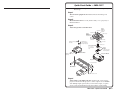
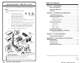
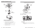
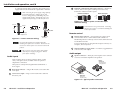
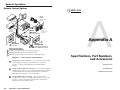
User’s Manual
MPA 181T
Mini Power Amplifier
www.extron.com
Extron Electronics, USA
Extron Electronics, Europe
Extron Electronics, Asia
Extron Electronics, Japan
1230 South Lewis Street
Anaheim, CA 92805
USA
714.491.1500
Fax 714.491.1517
Beeldschermweg 6C
3821 AH Amersfoort
The Netherlands
+31.33.453.4040
Fax +31.33.453.4050
135 Joo Seng Road, #04-01
PM Industrial Building
Singapore 368363
+65.6383.4400
Fax +65.6383.4664
Kyodo Building
16 Ichibancho
Chiyoda-ku, Tokyo 102-0082 Japan
+81.3.3511.7655
Fax +81.3.3511.7656
© 2006 Extron Electronics. All rights reserved.
68-1082-01
Rev. A
02 06
Precautions
Safety Instructions • English
This symbol is intended to alert the user of important
operating and maintenance (servicing) instructions
in the literature provided with the equipment.
This symbol is intended to alert the user of the
presence of uninsulated dangerous voltage within
the product's enclosure that may present a risk of
electric shock.
Caution
Read Instructions • Read and understand all safety and operating
instructions before using the equipment.
Retain Instructions • The safety instructions should be kept for future
reference.
Follow Warnings • Follow all warnings and instructions marked on the
equipment or in the user information.
Avoid Attachments • Do not use tools or attachments that are not
recommended by the equipment manufacturer because they may be
hazardous.
Consignes de Sécurité • Français
Ce symbole sert à avertir l’utilisateur que la
documentation fournie avec le matériel contient des
instructions importantes concernant l’exploitation
et la maintenance (réparation).
Ce symbole sert à avertir l’utilisateur de la présence
dans le boîtier de l’appareil de tensions dangereuses
non isolées posant des risques d’électrocution.
Attention
Lire les instructions• Prendre connaissance de toutes les consignes de
sécurité et d’exploitation avant d’utiliser le matériel.
Conserver les instructions• Ranger les consignes de sécurité afin de
pouvoir les consulter à l’avenir.
Respecter les avertissements • Observer tous les avertissements et
consignes marqués sur le matériel ou présentés dans la documentation
utilisateur.
Eviter les pièces de fixation • Ne pas utiliser de pièces de fixation ni
d’outils non recommandés par le fabricant du matériel car cela
risquerait de poser certains dangers.
Sicherheitsanleitungen • Deutsch
Dieses Symbol soll dem Benutzer in der im
Lieferumfang enthaltenen Dokumentation
besonders wichtige Hinweise zur Bedienung und
Wartung (Instandhaltung) geben.
Dieses Symbol soll den Benutzer darauf aufmerksam
machen, daß im Inneren des Gehäuses dieses
Produktes gefährliche Spannungen, die nicht isoliert
sind und die einen elektrischen Schock verursachen
können, herrschen.
Achtung
Lesen der Anleitungen • Bevor Sie das Gerät zum ersten Mal verwenden,
sollten Sie alle Sicherheits-und Bedienungsanleitungen genau
durchlesen und verstehen.
Aufbewahren der Anleitungen • Die Hinweise zur elektrischen Sicherheit
des Produktes sollten Sie aufbewahren, damit Sie im Bedarfsfall darauf
zurückgreifen können.
Befolgen der Warnhinweise • Befolgen Sie alle Warnhinweise und
Anleitungen auf dem Gerät oder in der Benutzerdokumentation.
Keine Zusatzgeräte • Verwenden Sie keine Werkzeuge oder Zusatzgeräte,
die nicht ausdrücklich vom Hersteller empfohlen wurden, da diese eine
Gefahrenquelle darstellen können.
Instrucciones de seguridad • Español
Este símbolo se utiliza para advertir al usuario sobre
instrucciones importantes de operación y
mantenimiento (o cambio de partes) que se desean
destacar en el contenido de la documentación
suministrada con los equipos.
Este símbolo se utiliza para advertir al usuario sobre
la presencia de elementos con voltaje peligroso sin
protección aislante, que puedan encontrarse dentro
de la caja o alojamiento del producto, y que puedan
representar riesgo de electrocución.
Precaucion
Leer las instrucciones • Leer y analizar todas las instrucciones de
operación y seguridad, antes de usar el equipo.
Conservar las instrucciones • Conservar las instrucciones de seguridad
para futura consulta.
Obedecer las advertencias • Todas las advertencias e instrucciones
marcadas en el equipo o en la documentación del usuario, deben ser
obedecidas.
Evitar el uso de accesorios • No usar herramientas o accesorios que no
sean especificamente recomendados por el fabricante, ya que podrian
implicar riesgos.
Warning
Power sources • This equipment should be operated only from the power source
indicated on the product. This equipment is intended to be used with a main
power system with a grounded (neutral) conductor. The third (grounding) pin is
a safety feature, do not attempt to bypass or disable it.
Power disconnection • To remove power from the equipment safely, remove all
power cords from the rear of the equipment, or the desktop power module (if
detachable), or from the power source receptacle (wall plug).
Power cord protection • Power cords should be routed so that they are not likely to
be stepped on or pinched by items placed upon or against them.
Servicing • Refer all servicing to qualified service personnel. There are no userserviceable parts inside. To prevent the risk of shock, do not attempt to service
this equipment yourself because opening or removing covers may expose you to
dangerous voltage or other hazards.
Slots and openings • If the equipment has slots or holes in the enclosure, these are
provided to prevent overheating of sensitive components inside. These openings
must never be blocked by other objects.
Lithium battery • There is a danger of explosion if battery is incorrectly replaced.
Replace it only with the same or equivalent type recommended by the
manufacturer. Dispose of used batteries according to the manufacturer's
instructions.
Avertissement
Alimentations• Ne faire fonctionner ce matériel qu’avec la source d’alimentation
indiquée sur l’appareil. Ce matériel doit être utilisé avec une alimentation
principale comportant un fil de terre (neutre). Le troisième contact (de mise à la
terre) constitue un dispositif de sécurité : n’essayez pas de la contourner ni de la
désactiver.
Déconnexion de l’alimentation• Pour mettre le matériel hors tension sans danger,
déconnectez tous les cordons d’alimentation de l’arrière de l’appareil ou du
module d’alimentation de bureau (s’il est amovible) ou encore de la prise secteur.
Protection du cordon d’alimentation • Acheminer les cordons d’alimentation de
manière à ce que personne ne risque de marcher dessus et à ce qu’ils ne soient
pas écrasés ou pincés par des objets.
Réparation-maintenance • Faire exécuter toutes les interventions de réparationmaintenance par un technicien qualifié. Aucun des éléments internes ne peut être
réparé par l’utilisateur. Afin d’éviter tout danger d’électrocution, l’utilisateur ne
doit pas essayer de procéder lui-même à ces opérations car l’ouverture ou le
retrait des couvercles risquent de l’exposer à de hautes tensions et autres dangers.
Fentes et orifices • Si le boîtier de l’appareil comporte des fentes ou des orifices,
ceux-ci servent à empêcher les composants internes sensibles de surchauffer. Ces
ouvertures ne doivent jamais être bloquées par des objets.
Lithium Batterie • Il a danger d'explosion s'll y a remplacment incorrect de la
batterie. Remplacer uniquement avec une batterie du meme type ou d'un ype
equivalent recommande par le constructeur. Mettre au reut les batteries usagees
conformement aux instructions du fabricant.
Vorsicht
Stromquellen • Dieses Gerät sollte nur über die auf dem Produkt angegebene
Stromquelle betrieben werden. Dieses Gerät wurde für eine Verwendung mit
einer Hauptstromleitung mit einem geerdeten (neutralen) Leiter konzipiert. Der
dritte Kontakt ist für einen Erdanschluß, und stellt eine Sicherheitsfunktion dar.
Diese sollte nicht umgangen oder außer Betrieb gesetzt werden.
Stromunterbrechung • Um das Gerät auf sichere Weise vom Netz zu trennen,
sollten Sie alle Netzkabel aus der Rückseite des Gerätes, aus der externen
Stomversorgung (falls dies möglich ist) oder aus der Wandsteckdose ziehen.
Schutz des Netzkabels • Netzkabel sollten stets so verlegt werden, daß sie nicht
im Weg liegen und niemand darauf treten kann oder Objekte darauf- oder
unmittelbar dagegengestellt werden können.
Wartung • Alle Wartungsmaßnahmen sollten nur von qualifiziertem
Servicepersonal durchgeführt werden. Die internen Komponenten des Gerätes
sind wartungsfrei. Zur Vermeidung eines elektrischen Schocks versuchen Sie in
keinem Fall, dieses Gerät selbst öffnen, da beim Entfernen der Abdeckungen die
Gefahr eines elektrischen Schlags und/oder andere Gefahren bestehen.
Schlitze und Öffnungen • Wenn das Gerät Schlitze oder Löcher im Gehäuse
aufweist, dienen diese zur Vermeidung einer Überhitzung der empfindlichen
Teile im Inneren. Diese Öffnungen dürfen niemals von anderen Objekten
blockiert werden.
Litium-Batterie • Explosionsgefahr, falls die Batterie nicht richtig ersetzt wird.
Ersetzen Sie verbrauchte Batterien nur durch den gleichen oder einen
vergleichbaren Batterietyp, der auch vom Hersteller empfohlen wird. Entsorgen
Sie verbrauchte Batterien bitte gemäß den Herstelleranweisungen.
Advertencia
Alimentación eléctrica • Este equipo debe conectarse únicamente a la fuente/tipo
de alimentación eléctrica indicada en el mismo. La alimentación eléctrica de este
equipo debe provenir de un sistema de distribución general con conductor
neutro a tierra. La tercera pata (puesta a tierra) es una medida de seguridad, no
puentearia ni eliminaria.
Desconexión de alimentación eléctrica • Para desconectar con seguridad la
acometida de alimentación eléctrica al equipo, desenchufar todos los cables de
alimentación en el panel trasero del equipo, o desenchufar el módulo de
alimentación (si fuera independiente), o desenchufar el cable del receptáculo de
la pared.
Protección del cables de alimentación • Los cables de alimentación eléctrica se
deben instalar en lugares donde no sean pisados ni apretados por objetos que se
puedan apoyar sobre ellos.
Reparaciones/mantenimiento • Solicitar siempre los servicios técnicos de personal
calificado. En el interior no hay partes a las que el usuario deba acceder. Para
evitar riesgo de electrocución, no intentar personalmente la reparación/
mantenimiento de este equipo, ya que al abrir o extraer las tapas puede quedar
expuesto a voltajes peligrosos u otros riesgos.
Ranuras y aberturas • Si el equipo posee ranuras o orificios en su caja/alojamiento,
es para evitar el sobrecalientamiento de componentes internos sensibles. Estas
aberturas nunca se deben obstruir con otros objetos.
Batería de litio • Existe riesgo de explosión si esta batería se coloca en la posición
incorrecta. Cambiar esta batería únicamente con el mismo tipo (o su equivalente)
recomendado por el fabricante. Desachar las baterías usadas siguiendo las
instrucciones del fabricante.
FCC Class A Notice
Note: This equipment has been tested and found to comply with the limits for a
Class A digital device, pursuant to part 15 of the FCC Rules. These limits are designed
to provide reasonable protection against harmful interference when the equipment is
operated in a commercial environment. This equipment generates, uses and can
radiate radio frequency energy and, if not installed and used in accordance with the
instruction manual, may cause harmful interference to radio communications.
Operation of this equipment in a residential area is likely to cause harmful
interference, in which case the user will be required to correct the interference at his
own expense.
Note: This unit was tested with shielded cables on the peripheral devices. Shielded
cables must be used with the unit to ensure compliance.
Extron’s Warranty
Extron Electronics warrants this product against defects in materials and
workmanship for a period of three years from the date of purchase. In the event of
malfunction during the warranty period attributable directly to faulty workmanship
and/or materials, Extron Electronics will, at its option, repair or replace said products
or components, to whatever extent it shall deem necessary to restore said product to
proper operating condition, provided that it is returned within the warranty period,
with proof of purchase and description of malfunction to:
USA, Canada, South America,
and Central America:
Extron Electronics
1230 South Lewis Street
Anaheim, CA 92805, USA
Asia:
Extron Electronics, Asia
135 Joo Seng Road, #04-01
PM Industrial Bldg.
Singapore 368363
Europe, Africa, and the Middle East:
Extron Electronics, Europe
Beeldschermweg 6C
3821 AH Amersfoort
The Netherlands
Japan:
Extron Electronics, Japan
Daisan DMJ Bldg. 6F,
3-9-1 Kudan Minami
Chiyoda-ku, Tokyo 102-0074
Japan
This Limited Warranty does not apply if the fault has been caused by misuse,
improper handling care, electrical or mechanical abuse, abnormal operating conditions
or non-Extron authorized modification to the product.
If it has been determined that the product is defective, please call Extron and ask for
an Applications Engineer at (714) 491-1500 (USA), 31.33.453.4040 (Europe),
65.6383.4400 (Asia), or 81.3.3511.7655 (Japan) to receive an RA# (Return Authorization
number). This will begin the repair process as quickly as possible.
Units must be returned insured, with shipping charges prepaid. If not insured, you
assume the risk of loss or damage during shipment. Returned units must include the
serial number and a description of the problem, as well as the name of the person to
contact in case there are any questions.
Extron Electronics makes no further warranties either expressed or implied with
respect to the product and its quality, performance, merchantability, or fitness for any
particular use. In no event will Extron Electronics be liable for direct, indirect, or
consequential damages resulting from any defect in this product even if Extron
Electronics has been advised of such damage.
Please note that laws vary from state to state and country to country, and that some
provisions of this warranty may not apply to you.
Quick Start Guide — MPA 181T
To install and set up an MPA 181T Mini Power Amplifier, follow
these steps:
Step 1
Turn all of the equipment off and disconnect it from the power
source.
Step 2
Mount the MPA 181T on a rack, under a desk, or on a projector, as
illustrated below.
Step 3
Attach the speakers to the MPA 181T.
Rear Plate
Rubber Pad
Extron
PMK 350
Above Projector
Mount Bracket
Cable Access
LIMITER
ON
OFF
LEVEL
BASS
TREBL
E
MINI
MPA
POWER
181T
AMPLI
FIER
Extron
Power Supply
for MPA 181
Drill pilot holes —
3/32” (2.4mm) dia.
1/4” (6.3 mm) deep
#8 Wood Screws (2 Plcs)
Each Side
Extron
MPA 181
Mini Power
Amplifier
Front Plate
Cover Sheet
Cable Access
Extron PMP
6”, 10“ or 12”
Projector Mount
Pole
BLE
TRE
1T
SS
BA
EL
LEV
MIN
ON
LIM
R
ITE
A 18FIER
MP PLI
R AM
WE
I PO
Extron
UPB 25
Universal Projector
Mounting Bracket
OFF
Under Desk
Machine Screw (2 Plcs)
Each Side
Projector Mount
Projector
LIM
ITER ON
OFF
LEV
EL
BAS
S
6" Deep Rack Shelf
TRE
BLE
MIN
I POWMP
A
ER
AM
18
PLI
1T
FIE
R
LIM
ITER ON
OFF
LEV
EL
BAS
S
TRE
BLE
MIN
Rack Mount
I POWMP
A
ER
AM
18
1T
PLI
FIE
R
LIM
ITER ON
OFF
LEV
EL
BAS
S
TRE
BLE
MIN
I POWMP
A
ER
AM
18
1T
PLI
FIE
R
LIM
ITER ON
OFF
(2) 4-40 x 3/16" screws
LEV
EL
BAS
S
TRE
BLE
MIN
I POWMP
A
ER
AM
18
1T
PLI
FIE
R
Step 4
Attach inputs to the MPA 181T unit and the audio source and/or
projector. Ensure that the projector’s audio output is set to variable
out. Multiple input options (RCA, 3.5 mm stereo input, or captive
screw) can be used simultaneously; this results in audio mixing.
MPA 181T • Quick Start Guide
QS-1
Quick Start Guide — MPA 181T, cont’d
Table of Contents
Chapter 1 • Introduction .......................................................... 1-1
Step 5
Connect power cords to the MPA 181T and other audio equipment.
Step 6
Adjust the MPA 181T input level, bass and
treble.
LEVEL
BASS
If connecting to a projector,
ensure that the volume on the
projector is at its lowest point,
then adjust the level of the
MPA 181T fully counterclockwise.
a.
TREBLE
MPA 181T
MINI POWER AMPLIFIER
b.
Set the projector volume to its maximum volume level
(no sound should come out).
c.
Return to the MPA 181T and raise the level until sound
distortion occurs, then lower slightly until distortion
disappears. This setting ensures that, whatever the
projector volume setting may be, no clipping occurs.
d.
Adjust bass and treble to preference.
Extron
SI 26CT
Two-way Ceiling
Speakers
S-video
Audio RCA
or
MPA
1T
18
UTS 70V
TP COM
OU
O)
ON
(M
C
E
V UT
10 L/M
R
VO
O)
L
(MON
V
70
4/8
Oh
Installation Overview .......................................................... 2-2
Mounting the MPA 181T .................................................... 2-2
Rack mounting ....................................................................... 2-3
Under-desk mounting ........................................................... 2-4
Projector mounting ............................................................... 2-5
Rear Panel Features .............................................................. 2-7
Power input ........................................................................... 2-7
Audio inputs .......................................................................... 2-8
Remote control ...................................................................... 2-9
Audio output ......................................................................... 2-9
Remote connector wiring ................................................... 2-11
Chapter 3 • Remote Operation ............................................ 3-1
Remote Control Options .................................................... 3-2
Appendix A • Specifications, Part Numbers,
and Accessories .............................................................................. A-1
D
TE
LIS 23
1T
.E.
US I.T
E
MOT
RE
TS
INPU
Chapter 2 • Installation and Operation ......................... 2-1
Front Panel Features .......................................................... 2-10
Setting Up the MPA 181T Amplifier ........................... 2-10
PC
DVD
About this Manual ................................................................ 1-2
About the MPA 181T ............................................................ 1-2
Features ...................................................................................... 1-2
ms
L
WER
PO
VCR
Extron
SI 26
R
V X
12 MA
3A
Composite
Audio RCA
Variable
Audio
Output
Extron
MPA 181T
Surface-mount
Speakers
Mini Power Amplifier
Specifications ......................................................................... A-2
Included Parts ......................................................................... A-5
Optional Accessories ........................................................... A-5
1
EC
OJ
PR
TO
R
2
OFF
ON
VO
LU
3
ME
RS-232
4
CO
NF
IG
4 IP
MLC
10
ME
VO
3
Extron
MLC 104 IP
Controller
M
VC
MUT
P
0 AA
10
E
2
Extron
VCM 100 AAP
Projector
1
Remote Control Options
QS-2
LU
IR Remote
Volume/Mute Controller in
AAP 100 Mounting Frame
1
IR Remote - (input selection and volume control through projector)
2
VCM 100 Volume/Mute Controller - (direct MPA 161T control)
3
MLC 104 IP Controller - (input selection and volume control through projector)
MPA 181T • Quick Start Guide
All trademarks mentioned in this manual are the properties of their respective owners.
68-1082-01
Rev. A
02 06
MPA 181T • Table of Contents
i
Table of Contents, cont’d
MPA 181T
1
Chapter One
Introduction
About this Manual
About the MPA 181T
Features
ii MPA 181T • Table of Contents
MPA 181T • Introduction
Introduction
About this Manual
This manual contains information about the Extron MPA 181T
Mini Power Amplifier with instructions on how to mount and
operate the unit.
About the MPA 181T
The Extron MPA 181T is a high performance, compact, single
channel power amplifier. The MPA 181T delivers 18 watts (rms)
for 70 Volt line level speakers, 14 watts (rms) for 4 ohm speaker
loads, and 8 watts (rms) for 8 ohm loads.
Volume and mute remote control — A rear panel, captive screw
“Remote” input connector allows for remote control of
volume adjustment and muting.
Flexible mounting options — The MPA 181T can be mounted
on a rack, projector, or under furniture.
External international power supply — The included
autoswitchable, 12 VDC, 3 A external power supply
provides worldwide power compatibility
(part #70-380-01).
The MPA 181T accepts balanced and unbalanced stereo and
mono inputs, and outputs a mono audio signal to drive for
4/8 ohm direct speakers or 70 volt line distribution speakers.
Front panel controls are provided for input level, bass, and
treble. The front panel also features a limiter switch which
automatically reduces the gain to prevent distortion (amplifier
clipping). The MPA 181T features remote control capability for
volume adjustment and muting. The MPA 181T, housed in a
1U, quarter rack width metal enclosure, can be mounted under
a desk, or mounted on a projector.
Features
Class D audio amplifier — The MPA 181T features improved,
class D technology for high efficiency and low distortion.
Compact size — The MPA 181T is housed in a 1U high, 1/4 rack
width, 6" deep, metal enclosure, allowing this amplifier to
fit in many unique applications.
Three balanced and unbalanced audio inputs — Balanced or
unbalanced input are available on the captive screw
connector, while the 3.5 mm stereo mini jack and RCA
connectors provide unbalanced input. The captive screw,
RCA and stereo mini jack connectors are actively mixed
together, then summed into a mono signal.
Selectable 70V or direct 4/8 ohm output — Fits distribution
sound or direct 4/8 ohm applications.
Quick plug speaker outputs — Speaker output is on a captive
screw connector for quick installation.
Front panel controls — Input level, bass, and treble can be
easily adjusted from the front panel.
Limiter switch — The limiter switch prevents output distortion
(clipping) and potential damage to speakers.
1-2
MPA 181T • Introduction
MPA 181T • Introduction
1-3
Introduction
MPA 181T
2
Chapter Two
Installation and Operation
Installation Overview
Mounting the MPA 181T
Rear Panel Features
Front Panel Features
Setting up the MPA 181T Amplifier
1-4
MPA 181T • Introduction
Installation and Operation
Installation Overview
To install and set up an MPA 181T, follow these steps:
1
2
3
Turn all of the equipment off. Make sure that the input
devices (DVD, VCR, PC, etc.), the MPA 181T unit, and the
output devices are turned off and disconnected from their
power source(s).
Rack mounting
1.
If feet were previously installed on the bottom of the
MPA 181T unit, remove them.
Mount the MPA 181T unit. See Mounting the MPA 181T
below.
2.
Attach the speakers and/or other output devices to the
MPA 181T. See Rear Panel Features later in this chapter for
more information.
Mount the unit on the rack shelf, using two
4-40 x 3/16" screws in opposite (diagonal) corners to
secure the MPA to the shelf. See figure 2-1 below.
3.
Install blank panel(s) or other unit(s) to the rack shelf.
4.
Insert the shelf into the rack, aligning the holes in the shelf
with those in the rack.
5.
Secure the shelf to the rack using the supplied machine
screws.
4
Attach inputs to the MPA 181T. See “Audio inputs” later
in this chapter for more information.
5
Connect power cords to the MPA 181T and other devices.
6
Following are detailed instructions on rack mounting, underdesk mounting, and projector mounting the MPA 181T unit (for
use in classrooms, personal offices, meeting rooms, etc.).
Adjust MPA 181T input level, bass and treble. See Setting
up the MPA Amplifier later in this chapter for detailed
information.
Mounting the MPA 181T
LIM
ITE
ON
R
OFF
LE
VE
L
BA
SS
TR
There are many optional accessories for mounting the
MPA 181T. They include the following part numbers:
MI
NI
EB
LE
6" Deep Rack Shelf
M
PO
PA
WE
R AM 18
1T
PL
IFI
ER
LIM
ITE
ON
R
OFF
LE
VE
L
BA
SS
TR
MI
NI
• PMK 300 Multi-Product Projector Mounting Kit
(70-374-01)
EB
LE
M
PO
PA
WE
R AM 18
1T
PL
IFI
ER
LIM
ITE
ON
R
OFF
LE
VE
L
BA
SS
TR
MI
NI
EB
LE
M
PO
PA
WE
R AM 18
1T
PL
IFI
ER
• PMK 350 Low Profile Multi-product Projector Mount Kit
(70-563-02, -03)
• RSU 126 1U 6” Universal Rack Shelf
(60-190-10)
LIM
ITE
R
ON
OFF
• RSU 129 1U Universal rack shelf
(60-190-01)
• RSB 129 1U 6” basic rack shelf
(60-604-01)
(2) 4-40 x 3/16" screws
LE
VE
L
BA
SS
TR
MI
NI
EB
LE
M
PO
PA
WE
R AM 18
1T
PL
IFI
ER
Figure 2-1 — Rack mounting the MPA 181T
• MBU 125 1U Under-Desk Mounting Kit
(70-077-01)
• MBD 129 1U Through-Desk Mounting Kit
(70-077-02)
2-2
MPA 181T • Installation and Operation
MPA 181T • Installation and Operation
2-3
Installation and operation, cont’d
6" Deep Rack Shelf
#8 Wood Screw (2 Plcs)
Each Side
LIM
ITE
1/4 Rack Width False Front
Face Plate
Drill pilot holes —
3/32” (2.4 mm) dia.
1/4” (6.3 mm) deep
ON
R
OFF
LE
VE
L
BA
SS
TR
EB
MI
NI
EB
TR
LE
SS
BA
M
PO
PA
WE
R AM 18
1T
PL
IFI
ER
LE
ON
LIM
R
ITE
VE
L
MI
NI
LE
1T
18 IER
IF
PL
MPA
AM
WER
PO
OFF
Machine Screw (2 Plcs)
Each Side
LIM
ITE
Figure 2-3 — Under-desk mounting
ON
R
OFF
(2) 4-40 x 3/16" screws
LE
VE
L
BA
SS
TR
EB
MI
NI
LE
M
PO
PA
WE
R AM 18
1T
PL
IFI
ER
Figure 2-2 — Mounting the MPA 181T on the
RSU shelf
Under-desk mounting
In addition to using the MPA 181T unit on a rack or projector, it
can also be mounted under furniture (or under a desk). Mount
the unit by using the optional mounting kit (part #70-077-01) for
furniture, as follows:
2-4
1.
Attach the mounting brackets to the amplifier with the
machine screws provided (figure 2-3).
2.
Hold the amplifier with the attached brackets against the
underside of the table or other furniture. Mark the
location of the screw holes of the bracket on the mounting
surface.
3.
Drill 3/32" (2 mm) diameter pilot holes, 1/4" (6.3 mm)
deep in the mounting surface at the marked screw
locations.
4.
Insert #8 wood screws into the four pilot holes. Tighten
each screw into the mounting surface until just less than
1/4" of the screw head protrudes.
5.
Align the mounting screws with the slots in the brackets
and place the interface against the surface, with the
screws through the bracket slots.
6.
Slide the unit slightly forward or back, then tighten all
four screws to secure it in place.
MPA 181T • Installation and Operation
Projector mounting
In addition to mounting the MPA 181T unit to a rack or under
furniture, it can also be projector mounted using the optional
kits PMK 350 (part #70-563-02, -03) or PMK 300 (part #70-37401). See figures 2-4 and 2-5 on the following page.
To projector mount the MPA 181T, do the following:
1.
If necessary, remove the feet from the bottom of the device
to be installed.
2.
Mount the MPA 181T to one of the bracket’s three
mounting plates. The device can be horizontally mounted
facing either up or down, whichever is most convenient.
See the illustrations on the following page.
Use two supplied 4-40 x 3/16 screws in opposite
(diagonal) corners to secure the device to the bracket.
MPA 181T • Installation and Operation
2-5
Installation and operation, cont’d
Rear Plate
Above Projector
Mount Bracket
Secure the bracket to the U-bolt onto the ceiling pole with
the included hex nuts, washers, and lock washers.
6.
Mini Power
Amplifier
Rubber Pad
Clamping
Plate
Extron
MPA 181T
Cable Access
Mini Power
Amplifier
ON
Rubber Pad
LEV
EL
BAS
S
TRE
BLE
COM 70V
MPA 181T
Cover Sheet
Extron
PMP
4/8 Ohms
LISTED
1T23
I.T.E.
C
10V
VOL/MUTE
REMOTE
POWER
INPUTS
Front Plate
for MPA 181T
Extron
PMK 300
Multi Product Projector
Mount Kit
Cable Access
6”, 10“ or 12”
Projector Mount
Pole
L (MONO) R
US
70V
U-Bolt
Extron
Power Supply
OUTPUTS
I POWMP
A 181
ER
AMP
T
LIFI
ER
(MONO)
MIN
R
OFF
L
LIMI
TER
12V
3A MAX
Extron
PMK 350
Extron
MPA 181T
Extron
UPB 25
Universal Projector
Mounting Bracket
Figure 2-5 — Mounting the PMK 300
Rear Panel Features
5
REMOTE
INPUTS
C
(MONO)
POWER
L
LISTED
1T23
I.T.E.
MPA 181T
OUTPUTS
10V
VOL/MUTE
L (MONO) R
Projector
US
COM 70V
70V
4/8 Ohms
R
12V
3A MAX
Figure 2-4 — Using the PMK 350 projector
mounting kit for the MPA 181T
3.
Affix the black rubber pad to the mounting plate.
4.
Place the U-bolt behind, then through the two holes of the
mounting plate to wrap around the ceiling pole.
For a typical (1.5" to 2.0" diameter) pole — The supplied
U-bolt fits a typical ceiling pole.
5.
2-6
1
2
3
4
6
7
Figure 2-5 — MPA 181T back panel
Power input
1
Power connection — Plug the external 12 VDC power
supply into this connector. The power supply is included
with the unit.
Place the bracket on the opposing side of the ceiling pole
and through the U-bolt legs.
MPA 181T • Installation and Operation
MPA 181T • Installation and Operation
2-7
Installation and operation, cont’d
To verify the polarity before connection, plug in the power
supply with no load and check the output with a voltmeter.
CAUTION
4
Unbalanced Output
Balanced Output
AUDIO
Tip
Ring
Sleeve (s)
Tip
Ring
R
R
AUDIO
L
Tip
See Caution
Sleeve (s)
Tip
See Caution
L
When connecting the power supply, voltage polarity
is extremely important. Applying power with
incorrect voltage polarity could damage the power
supply and the interface. Identify the power cord
negative lead by the ridges on the side of the cord.
Balanced or unbalanced audio input connector — Marked “L”
and “R”, this 3.5 mm captive screw input is for bare wire,
balanced or unbalanced audio signals.
Figure 2-7 — 3.5 mm captive screw audio input
connector wiring
Smooth
Ridges
Connect the sleeves to ground (Gnd). Connecting
the sleeve to a negative (-) terminal will damage the
audio output circuits.
CAUTION
A
A
SECTION A–A
0.2” (5 mm) MAX
Power Supply
Output Cord
Remote control
Captive Screw
Connector
5
Figure 2-6 — Power connector wiring
Do not tin the stripped power supply leads before
installing the captive screw connector. Tinned wires are
not as secure in the captive screw connectors and could
pull out.
The two power cord wires must be kept separate
while the power supply is plugged in. Remove
power before continuing.
Audio inputs
Remote input connector — An optional 5-pin, captive screw
connector that allows a wall mounted audio controller or
MediaLink product to remotely control volume and mute levels
for the MPA 181T unit.
For more information on using the remote input connector, see
Chapter 3, Remote Operation.
6
Output impedance toggle switch — A switch to toggle between
a 70 volt or 4/8 ohm output.
Audio output
7
Speaker connector — This 4-pin, 5 mm captive screw connector
is used to connect the amplifier to the speakers.
There are three choices of input connectors (RCA, 3.5 mm
stereo, and captive screw) available on the rear panel for
adapter-free connections.
Extron
SI 3CT LP
70V/100V/8 ohm
Ceiling Speakers
All inputs are actively mixed together then summed into a
mono signal.
MPA
18
1T
D
TE
LIS 23
1T
2
RCA input connector — Plug an RCA audio source to this line
level input.
UTS 70V
TP COM
OU
.E.
US I.T
RE
TS
INPU
O)
ON
(M
E
MOT
E
V UT
10 L/M
R
VO
O)
L
(MON
C
70
4/8
V
ms
Oh
L
WER
PO
R
3
3.5 mm stereo input — Plug a 3.5 mm audio micro cable into
this stereo jack.
V X
12 MA
3A
Extron
MPA 181T
Mini Power
Amplifier (70V)
Figure 2-8 — Typical speaker connection
2-8
MPA 181T • Installation and Operation
MPA 181T • Installation and Operation
2-9
Installation and operation, cont’d
4/8 ohm output
COM 70V
70V
4/8 OHM
+ -
70 volt output
1.
If connecting to a projector, ensure that the volume on the
device is at its lowest point, then adjust the level of the
MPA 181T fully counterclockwise.
2.
Set the projector volume to its maximum volume level.
No sound should come out.
3.
Return to the MPA and raise the level until sound
distortion occurs, then lower the level slightly until any
distortion disappears. This setting ensures that, whatever
the projector volume setting may be, no clipping occurs.
4.
Adjust bass and treble to preference.
COM 70V
70V
4/8 OHM
+ -
+
COM 70V
Figure 2-9 — Output speaker wiring
The 70 volt output and the 4/8 ohm output cannot
be used simultaneously.
Remote connector wiring
Front Panel Features
Options for remote control include the Extron VCM 100 and
VC 50 volume controllers. Third party 10k potentiometer
volume controllers can also be connected to this port.
ON
1
LEVEL
BASS
TREBLE
LIMITER
OFF
As shown below, Pin 1 is 10 VDC reference voltage. Pin 2 is
volume control DC voltage; range is 0 to 10 V, where 0 V is mute
and 10 V provides maximum volume. Pin 3 is ground.
MPA 181T
All nominal levels are at ±10%.
MINI POWER AMPLIFIER
1
Power LED — A green LED lights to indicate that the unit is
receiving power.
2
Limiter toggle switch — When the limiter is switched to “On”,
the MPA will automatically reduce the level to prevent the
amplifier from clipping.
3
Potentiometer adjustments — These three potentiometers
optimize level, bass, and treble adjustments.
Setting Up the MPA 181T Amplifier
When setting up volume control, ensure that the projector
output is set to variable out. Consult the projector’s user
manual for detailed instructions on its calibration.
To adjust the MPA 181T input level, bass, and treble, do the
following:
MPA 181T • Installation and Operation
REMOTE
Extron
STP 22
Cable
1 2 3
10V
VOL/MUTE
10V
Figure 2-10— MPA 181T front panel
2-10
Red
Black
Ground
3
VOL/
MUTE
2
VOLUME
MUTE
VCM 100
Figure 2-11— Pinout diagram for VCM 100 MAAP
remote connector
MPA 181T • Installation and Operation
2-11
Installation and operation, cont’d
1
MPA 181T
MAX
2K
10K
2
MIN
3
GND
Figure 2-12 — Pinout diagram for a third party
volume potentiometer
See Chapter 3, Remote Operation for more information on the
three options (IR remote, MLC series, or DC volume/mute
controller) for remote control.
3
Chapter Three
Remote Operation
Remote Control Options
2-12
MPA 181T • Installation and Operation
Remote Operation
Remote Control Options
MPA 181T
Extron
SI 26CT
PC
DVD
Two-way Ceiling
Speakers
S-video
Audio RCA
or
MPA
1T
18
D
TE
LIS 23
1T
UTS 70V
TP COM
OU
.E.
US I.T
E
MOT
RE
TS
INPU
O)
ON
(M
C
E
V UT
10 L/M
R
VO
O)
L
(MON
V
70
4/8
Oh
ms
L
WER
PO
VCR
Extron
SI 26
R
V X
12 MA
3A
Extron
MPA 181T
Composite
Audio RCA
Variable
Audio
Output
Surface-mount
Speakers
Mini Power Amplifier
1
EC
OJ
PR
TO
R
2
OFF
ON
VO
LU
3
ME
RS-232
4
CO
NF
IG
4 IP
MLC
10
ME
VO
3
Extron
MLC 104 IP
Controller
M
VC
MUT
P
0 AA
10
E
2
Extron
VCM 100 AAP
Projector
1
Remote Control Options
LU
IR Remote
Volume/Mute Controller in
AAP 100 Mounting Frame
1
IR Remote - (input selection and volume control through projector)
2
VCM 100 Volume/Mute Controller - (direct MPA 161T control)
3
MLC 104 IP Controller - (input selection and volume control through projector)
Figure 3-1 — Three remote control options
1
2
3
3-2
Using the projector’s IR remote — For a projector with variable
audio outputs, use the projector’s IR remote to control the
projector’s volume, which effectively controls the MPA’s
volume.
Extron VCM 100 and mute controller — For a projector without
variable audio outputs, or for a system designed to control MPA
volume directly, use a 10k ohm potentiometer to control the
MPA directly via the remote port on the MPA.
Using a MediaLink™ Controller — For a projector with
variable audio output, use a MediaLink controller to control the
projector’s volume via RS-232 or the projector’s IR remote to
effectively control the MPA volume.
MPA 181T • Remote Operation
A
Appendix A
Specifications, Part Numbers,
and Accessories
Specifications
Included Parts
Optional Accessories
Specifications, Part Numbers, and Accessories
Specifications
Audio
Frequency response
8 ohm direct output ......... 20 Hz to 20 kHz, ±1.5 dB
70 V output ....................... 110 Hz to 20 kHz, +0.5/-3 dB
THD + Noise ................................ 0.1% @ 1 kHz at nominal level
(1 watt, 8 ohm load, or 70 V output)
S/N ................................................ >72 dB @ 20 Hz to 20 kHz at maximum
output (unweighted)
CMRR ............................................ >80 dB @ 1 kHz, >70 dB @ 20 kHz
Bass adjustment ........................... ±10 dB @ 100 Hz (reference) to 1 kHz
(2 dB tolerance)
Treble adjustment ........................ ±10 dB @ 10 kHz (reference) to 1 kHz
(2 dB tolerance)
Audio input
Number/signal type ................... 1 stereo/mono, balanced/
unbalanced input
2 stereo/mono, unbalanced inputs
(The three inputs are individually
buffered and mixed together. Stereo
signals are actively summed into a mono
signal)
Connectors .................................... (1) 3.5 mm captive screw connector, 5 pole
(main input)
(1) 3.5 mm mini audio jack (tip, ring,
sleeve)
1 pair RCA
Impedance .................................... 18k ohms unbalanced, 23k ohms
balanced, DC coupled
Nominal level
RCA and mini jack .......... -10 dBV (316mVrms) (unbalanced)
Captive screw ................... +4 dBu, (1.23mVrms) (balanced)
Maximum level
Level pot. at 11 o’clock .... +6 dBV (unbalanced), +16 dBu (balanced)
at 1% THD+N
Level pot. at 9 o’clock ...... +16 dBV (unbalanced), +23 dBu (balanced)
at 1% THD+N
A-2
MPA 181T • Specifications, Part Numbers, and Accessories
Input level sensitivity ................. -16 dBV (158 mV) from unbalanced input
for maximum output (18 watts at 70 V
output and with the level set to
maximum) before clipping
0 dBu = 0.775 Vrms, 0 dBV = 1 Vrms, 0 dBV
2 dBu
Audio output
Number/signal type ................... 1 single channel (mono) 70 V output or
1 direct 4 or 8 ohm speaker output
Connectors .................................... (1) 5 mm captive screw connector, 4 pole
Minimum load impedance ......... 2 ohms
Amplifier type .............................. Improved Class D
Continuous power with a full load and 1% THD
70 V system ....................... 18 watts (rms)
At 4 ohms .......................... 14 watts (rms)
At 8 ohms .......................... 8 watts (rms)
Damping factor ............................ >30 (with a 4 ohm load)
Control/remote — amplifier
Control port .................................. (1) 3.5 mm captive screw connector, 5 pole
Pin configuration ......................... Pin 1 = 10 V, pin 2 = volume/mute control
voltage, pin 3 = GND
General
External power supply ............... 100 VAC to 240 VAC, 50/60 Hz, external,
autoswitchable; to 12 VDC, 3 A (max.),
regulated
Power input requirements ......... 12 VDC, up to 3 A
Temperature/humidity .............. Storage: -40 to +158 °F (-40 to +70 °C) /
10% to 90%, noncondensing
Operating: +32 to +122 °F (0 to +50 °C) /
10% to 90%, noncondensing
Rack mount ................................... Yes, with optional 1U rack shelf, part #60190-10 or 60-604-10. Also furniture
mountable with optional Mini UnderDesk Mounting Kit, #70-077-10 or
mountable to a projector mount with
optional kits PMK 350 (#70-563-02, -03) or
PMK 300 (#70-374-01).
Enclosure type .............................. Metal
MPA 181T • Specifications, Part Numbers, and Accessories
A-3
Specifications, Part Numbers, and Accessories
Enclosure dimensions ................. 1.7" H x 4.3" W x 6.0" D (1U high, quarter
rack wide)
4.3 cm H x 10.9 cm W x 15.2 cm D
(Depth excludes connectors.)
Product weight ............................. 1.2 lbs (0.5 kg)
Shipping weight ........................... 6 lbs (3 kg)
Vibration ....................................... ISTA 1A in carton (International Safe
Transit Association)
Included Parts
These items are included in each order of a MPA 181T unit:
Included parts
Part number
MPA 181T Mini Power Amplifier
60-747-01
12 VDC, 3 A external power supply
70-380-01
(2) 5-pin, 3.5 mm captive screw conn.
10-319-10
2-pin, 3.5 mm captive screw conn.
10-319-03
4-pin, 5 mm terminal block plug
10-163-14
MPA 181T Mini Power Amplifier User’s Manual
IEC power cord
Tweeker
Optional Accessories
Accessories
PMK 300 Multi-Product Proj Mount Kit
Part number
70-374-01
PMK 350 Low Profile Multi-product Proj Mount Kit
70-563-02, -03
A-4
MPA 181T • Specifications, Part Numbers, and Accessories
RSU 126 1U 6” Universal Rack Shelf
60-190-10
RSU 129 1U Universal rack shelf
60-190-01
RSB 129 1U 6” basic rack shelf
60-604-01
MBU 125 1U Under-Desk Mounting Kit
70-077-01
MBD 129 1U Through-Desk Mounting Kit
70-077-02
VCM 100 AAP volume and mute control
70-396-11,
-21, -51
VCM 100 MAAP volume and mute control
70-397-11,
-21, -51
MPA 181T • Specifications, Part Numbers, and Accessories
A-5
Specifications, Part Numbers, Accessories, cont’d
A-6
MPA 181T • Specifications, Part Numbers, and Accessories