1
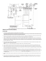
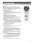
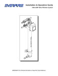
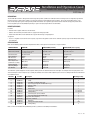
Installation and Operation Guide
Parallel 202 &/or Surge Tank Retrofit Kit
EV9336-52
DESCRIPTION
The Parallel 202 Pre-Filter is designed to remove larger dirt particles (10 microns-nominal) from the incoming water to a high flow, high volume
fountain machine, a coffee maker and/or an ice machine in order to extend the life of the fine filters. The surge (accumulator) tank is a prepressurized, diaphragm-type tank designed to provide filtered water to a high flow, high volume fountain machine during peak periods when
increased gallons per minute (GPM) and pounds per square inch (PSI) requirements are demanded.
BENEFITS/FEATURES
Pre-Filter
• Ideal for water supplies with excessive dirt loads.
• Reduces dirt and other particulate matter in supply water through pre-filter.
• Water meter determines water demand and usage for all beverage using equipment.
Surge Tank
• Assures a 12 gallon reserve for the extra capacity surge tank and 5 gallon reserve for the standard capacity surge tank of filtered water during
peak demands.
SPECIFICATIONS
Refer to the following table for the most important Pre-Filter and Surge Tank characteristics and part numbers:
CHARACTERISTIC
PREFILTER
SURGE TANK (standard)
SURGE TANK (extra capacity)
(21⁄2" additional height required
for cartridge change out)
153⁄8" Dia. x 22" H
153⁄8" Dia. x 315⁄8" H
3/4" NPT female
10 gpm
10 psi
90 psi (non-shock)
3/4" NPT male
10 gpm
10 psi
100 psi (non-shock)
3/4" NPT male
10 gpm
10 psi
100 psi (non-shock)
100˚F (38˚C)
100˚F (38˚C)
100˚F (38˚C)
32 ⁄2 pounds
411⁄2 pounds
EV9100-24
28 pounds
68 pounds
EV9336-50
35 pounds
133 pounds
EV9336-51
26 ⁄16" H x 28 ⁄4" W x 8 ⁄2" D
1
Dimensions (overall)
Inlet Connection
Max. Flow Rate
Min. Pressure
Max. Pressure
Max. Temperature
(cold water use only)
Shipping Weight
Operating Weight
Part Number
1
3
1
The indention system employed in the description column permits the determination of the next higher assembly to which the part pertains and
also the detail parts which comprise any assembly. Assemblies are listed first with component parts of each assembly listed with the indention of
one additional space.
Index No.
*1
*2
*3
*4
*5
*6
**7
**8
**9
*10
*
*
*11
*12
*13
Part No.
EV9100-24
EV3098-41
EV9108-40
EV3097-09
EV3093-53
EV3034-83
EV3100-93
EV3047-10
EV3099-62
EV3057-83
EV3092-54
EV9336-51
EV9336-50
EV3034-83
EV3047-10
EV3099-62
Description
Pre-filter, parallel 202
Sump
Cartridge, ec-204 (package of 6)
Kit, o-ring (package of 3 #ev3093-50 o-rings)
Wrench, sump
Ball valve
Water meter
Tubing, plastic (bulk length)
Clamp, tubing
Connector, 3/4” npt x 3/.4” Barb
Pressure relief (part of 3101-08 cap)
Surge tank, extra capacity
Surge tank, standard
Ball valve
Tubing, plastic (bulk length)
Clamp, tubing
Quantity per Assy.
1
2
2
1
1
1
As required
As required
2
2
1
1
1
120”
2
Note: ** items not included with parallel 202 pre-filter system due to variability of installations.
EV3100-91C FE05
Figure 1. Parallel 202 Pre-Filter and/or Extra Capacity Surge Tank or Standard Surge Tank Retrofit Kit
PARALLEL-202 PRE-FILTER (EV9100-24)
INSTALLATION
1. Shut off water and electrical power to all affected food service equipment.
It is important that the installation of the pre-filter be clean and sanitary. All water-contact parts shall be immersed in chlorinated water (a
capful of bleach per bucket of water) at the start of the installation procedure.
2. Disconnect electrical power and water from the high flow filter system to be served by the Parallel-202 Pre-Filter. Close the inlet water ball
valve on the high flow filter system. Disconnect the inlet water line from the high flow filter system ball valve.
3. Select a suitable location near the high flow filter system (not to exceed maximum of 10 ft.) for mounting the pre-filter and install mounting
hardware 16" apart (pre-filter mounting plate may be used as a template). The pre-filters overall dimensions are 261⁄16" high x 283⁄4" wide x 81⁄2"
deep. Allow at least 21⁄2" below the pre-filter to change out the cartridges. Be sure the mounting hardware is capable of supporting 42 pounds
(pre-filter weight when in service).
4. Unscrew both sumps from the pre-filter using the sump wrench, if necessary. Do not lose the O-ring seals. Remove the cartridges and set
aside with the sumps and O-rings (if removed).
NOTE: Be sure to use a high quality pipe joint compound or Teflon® tape on all threaded connections.
5. Install a 3/4" NPT x 3/4" barb connector into the the outlet tee of the pre-filter and the inlet water ball valve on the high flow filter system.
6. Measure distance between the barbs on the connectors and cut tubing (not supplied) to this length plus an additional 2". Slide two tubing
clamps (not supplied) onto the tubing and install the tubing ends fully onto the connector barbs (not supplied). Fully tighten the tubing clamps
to secure the tubing onto each connector barb.
7. Check that the sump O-ring is lubricated. If additional lubricant is required use only a high grade silicone lubricant. Install the O-ring in its
respective groove in the sump, remove protective wrap, position the cartridge on the guide seat in the bottom of the sump, then firmly screw
the sump into the cap and tighten with the provided sump wrench. DO NOT USE A PIPE WRENCH. Repeat this procedure for the second
cartridge and sump.
8. Connect the inlet water line disconnected from the inlet water ball valve on the high flow filter system the inlet water ball valve on the prefilter.
9. Turn on water to the pre-filter, place the pre-filter ball valve in the ON position (handle parallel to water flow), and press the red pressure
relief button on one cap to open the pressure relief valve, purging air from the high flow filter system. When water vents out, release the
button and repeat for the pressure relief on the second cap.
10. Inspect the high flow filter system for any water leakage, tightening all connections as required until no leakage is observed. Turn on water
and electrical power to all affected food service equipment. The filter system is now in service. Always keep a supply of replacement
cartridges on hand.
SERVICE
No routine (daily, weekly, monthly, etc.) servicing of the pre-filter is required under normal operating conditions. The only scheduled servicing
of the pre-filter is to change-out the cartridges whenever the water meter denotes a quantity of supply water (predetermined by the system
requirements) has passed through the system.
CARTRIDGE CHANGE
Replace filter cartridges when they become excessively dirty, when the pressure gauge on the high flow filter system indicates extremely low
pressure during water flow, or when changes in taste and odor are detected.
1. Turn off inlet and outlet water valves and press the red pressure relief valve on the filter cap.
2. Unscrew the sump from the filter cap using the sump wrench if necessary. Remove the used cartridge an empty the water from the sump.
The O-ring provides a water tight seal. Be sure the O-ring is properly seated and lubricated.
3. If the O-ring on the sump feels dry, lubricate it with a high grade silicone lubricant and reinstall in its groove in the sump.
4. Clean the sump with a mild solution of unscented dishwashing detergent. DO NOT use soap, strong or scented detergents, chemical
cleansers or abrasives.
5. Position the replacement cartridge on the guide seat in the bottom of the sump. Then firmly screw the sump into the cap with the sump
wrench. DO NOT USE A PIPE WRENCH.
SURGE TANK
STANDARD:
EV9336-50
EXTRA CAPACITY:
EV9336-51
INSTALLATION:
The surge tank must be installed on the effluent side of the high flow filter system. The surge tank has a 20±2 psi air charge WHEN EMPTY for
proper performance. This must be checked before installation and re-charged if necessary. Refer to SERVICE.
It is important that the installation of the surge tank be clean and sanitary. All water-contact parts shall be immersed in chlorinated water (a
capful of bleach per bucket of water) at the start of the installation procedure.
1. Shut off water and electrical power to all affected food service equipment.
2. Disconnect electrical power and water from the high flow filter system to be served by the Surge Tank. Close the inlet water ball valve on the
high flow filter system and bleed water pressure from the system using the flushing valve on the high flow filter system.
The extra capacity (12 gallon) surge tank weighs 133 pounds and the standard (5 gallon) tank weighs 68 pounds when full. If the installation
location in not on the floor, be certain its stand/shelf/platform is capable of safely supporting this weight.
3. Select a suitable location near the high flow filter system (not to exceed maximum of 10 feet) for the surge tank. The surge tanks overall
dimensions are 153⁄8" diameter x 315⁄8" high for the extra capacity surge tank and 153⁄8" diameter X 22" in height for the standard surge tank.
4. Disconnect the water line between the high flow filter system and the high flow, high volume fountain machine at the plated cross containing
the activation valve.
NOTE: Be sure to use a high quality pipe joint compound or Teflon® tape on all threaded connections.
5. Install a 3/4" NPT x 1/2" NPT bushing into the the universal cross on the high flow filter system.
6. Install a 1/2" NPT tee into the bushing and orient as shown in figure 1.
7. Install a 1/2" NPT x 3/4" barb connector into the branch of the plated cross and a 1/2" NPT x 3/4" barb elbow into the run of the plated cross.
Orient the elbow as shown in figure 1.
8. Reconnect a water line between the high flow filter system and the high flow, high volume fountain machine using appropriate connectors
for the installation. One means is to slide a tube clamp onto the tubing (not provided) disconnected from the high flow filter system at the
activation valve plated cross and install the tubing fully onto the newly installed 1/2" NPT x 3/4" barb elbow. Fully tighten the tubing clamp to
secure the tubing onto the elbow barb.
9. Remove the protective cap from the nipple extending from the bottom of the extra capacity surge tank. For the standard capacity surge tank,
remove styrofoam block, clean threads of styrofoam chips and remove plug from threaded, nipple fitting.
For standard surge tank, make sure plastic plug located in nipple threaded fitting is removed to insure proper installation of surge tank.
10. Install a ball valve onto the nipple and orient in any position convenient for operation of the handle. Install a 3/4" NPT x 3/4" barb connector
into the ball valve.
11. With the surge tank at any convenient position near the high flow filter system, cut the tubing to length (maximum length 10ft.) and slide two
tubing clamps onto the tubing. Install the tubing end fully onto the 3/4" NPT x 3/4" barb connector at the surge tank ball valve. Fully tighten one
tubing clamp to secure the tubing onto the connector barb.
Disinfection of the surge tank is required prior to placing it into service.
12. Pour a capful of bleach into the tubing connected in step 11 onto the 3/4” NPT x 3/4” barb connector at the surge tank ball valve and then
immediately connect the loose tubing end to the 1/2” NPT x 3/4” barb connector installed in step 7. Fully tighten the remaining tubing clamp
to secure the tubing onto the connector barb.
13. Place the high flow filter system into service by opening the inlet water ball valve. Open the surge tank ball valve and allow the surge tank to
fill for three minutes.
14. Connect a hose to the high flow filter system activation valve connected to the plated cross. Close inlet valve to the highflow system. Open
the flush valve and allow the water to drain to waste for five minutes in order to expel chlorinated water from the surge tank or until no
chlorine odor is detected. Then close the flush valve and open the inlet valve to the high flow system. If new cartridges installed, flush high
flow system for five minutes. The high flow filter system and surge tank is now in service.
15. Inspect the system for any water leakage, tightening all connections as required until no leakage is observed.
16. After installation of the surge tank, it will be necessary to close the surge tank ball valve prior to removing cartridges from the pre-filter or
high flow filter system.
Before removing any filter cartridges always close the ball valve on the surge tank.
SERVICE
No routine servicing of the surge tank is required under normal operating conditions although periodic sanitizing (annual) is recommended. The
only servicing of the surge tank occurs if the internal air bladder pressure (excluding water pressure) is not 20±2 psi when empty. A conventional
tire valve is provided at the top of the extra capacity surge tank and near the bottom of the standard surge tank to monitor and adjust the internal
pressure.
LIMITED WARRANTY
COMMERCIAL WATER TREATMENT EQUIPMENT
You have just purchased one of the finest water treatment units made. As an expression of our confidence in Everpure products, this product is warranted
against defects in material and workmanship to the original end-user when installed in accordance with Everpure specifications. The warranty period
commences from the date of purchase and is administered as follows:
For a period of ONE YEAR
Replaceable elements (i.e., filter & water treatment cartridges)*
For a period of FIVE YEARS
The entire system (excluding replaceable elements)
*This is for material & workmanship, not filter or water treatment cartridge life.
The unit must be used in operating conditions that conform to Everpure’s recommended design guidelines. This warranty will not apply if the unit has been
modified, repaired or altered by someone not authorized by Everpure.
If a part described above is found defective within the specified period, you should notify Everpure technical service at the phone number listed below.
Any part found defective within the terms of this warranty will be repaired or replaced (at Everpure’s discretion) by your local dealer or Everpure technical
service. You pay only freight from our factory and local dealer charges. Any repaired or replaced warranty item will be incorporated under the original
warranty terms of the existing system.
We are not responsible for damage caused by accident, fire, flood, freezing, Act of God, misuse, misapplication, neglect, oxidizing agents (such as chlorine,
ozone, chloramines and other related components), alteration, installation or operation contrary to our printed instructions, or by the use of accessories or
components which do not meet Everpure’s specifications. Refer to the specifications section in the Installation and Operating manual for approved application
parameters.
Our product performance specifications are furnished with each water treatment unit. TO THE EXTENT PERMITTED BY LAW, EVERPURE DISCLAIMS ALL
IMPLIED WARRANTIES, INCLUDING WITHOUT LIMITATION WARRANTIES OF MERCHANTABILITY AND FITNESS FOR PARTICULAR PURPOSE; TO THE EXTENT
REQUIRED BY LAW, ANY SUCH IMPLIED WARRANTIES ARE LIMITED IN DURATION TO THE PERIOD SPECIFIED ABOVE FOR THE ENTIRE WATER TREATMENT
UNIT. As a manufacturer, we do not know the characteristics of your water supply or the purpose for which you are purchasing this product. The quality of
water supplies may vary seasonally or over a period of time, and your water usage rate may vary as well. Water characteristics can also differ considerably
if this product is moved to a new location. For these reasons, we assume no liability for the determination of the proper equipment necessary to meet your
requirements, and we do not authorize others to assume such obligations for us. Further, we assume no liability and extend no warranties, express or implied,
for the use of this product with a non-potable water source or a water source which does not meet the conditions for use described in the owner’s guide or
performance data sheet for this product. OUR OBLIGATIONS UNDER THIS WARRANTY ARE LIMITED TO THE REPAIR OR REPLACEMENT (AT EVERPURE’S
DISCRETION) OF THE FAILED PARTS OF THE WATER TREATMENT UNIT, AND WE ASSUME NO LIABILITY WHATSOEVER FOR DIRECT, INDIRECT, INCIDENTAL,
CONSEQUENTIAL, SPECIAL, GENERAL OR OTHER DAMAGES.
Some states do not allow the exclusion of implied warranties or limitations on how long an implied warranty lasts, so the above limitation may not apply to
you. Similarly, some states do not allow the exclusion of incidental or consequential damages, so the above limitation or exclusion may not apply to you. This
warranty gives you specific legal rights, and you may also have other rights which vary from state to state. Consult your telephone directory for your local
independently operated Everpure dealer, or write Everpure for warranty and service information.
For sales, replacement components, and service, contact your Everpure dealer or:
Everpure, LLC: 1040 Muirfield Drive • Hanover Park, Illinois 60133 • 800.323.7873
In Europe: Toekomstlaan 30 • B-2200 Herentals, Belguim
In Japan: Hashimoto MN Bldg. 7F • 3-25-1 Hashimoto Sagamihara-Shi • Kanagawa 229-1103, Japan
Printed in U.S.A.
Technical Service
800.942.1153
www.everpure.com
EV3100-91C FE05