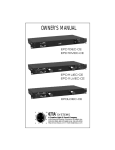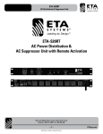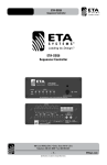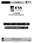
1
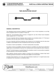
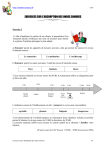
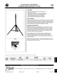
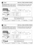
ETA-ECM2063
AC Power Distribution Sequencer
ETA-ECM2063
AC Power Distribution Sequencer
Raceway System
1601 Jack McKay Blvd. • Ennis, Texas 75119 U.S.A.
Telephone: 800-321-6699 • Fax: 800-996-3821
– 1 –
Specifications are subject to change without notice.
ETAsys.com
ETA-ECM2063
AC Power Distribution Sequencer
TABLE OF CONTENTS
Important Safety Instructions .................................................................................................................. 3
Introduction ............................................................................................................................................ 5
Key Features........................................................................................................................................... 5
Applications ............................................................................................................................................ 5
Raceway AC Inlet Knockouts................................................................................................................... 6
Raceway Mounting Rails ......................................................................................................................... 6
Configuring the ETA-ECM2063 ............................................................................................................... 7
Wiring the AC Mains................................................................................................................................ 8
Specifications......................................................................................................................................... 13
Warranty................................................................................................................................................. 16
1601 Jack McKay Blvd. • Ennis, Texas 75119 U.S.A.
Telephone: 800-321-6699 • Fax: 800-996-3821
– 2 –
Specifications are subject to change without notice.
ETAsys.com
ETA-ECM2063
AC Power Distribution Sequencer
IMPORTANT SAFETY INSTRUCTIONS
The lightning flash with arrowhead symbol within an
equilateral triangle, is intended to alert the user to the
presence of uninsulated “dangerous voltage “ within the
product’s enclosure that may be of sufficient magnitude
to constitute a risk of electric shock to persons.
The exclamation point within an equilateral triangle is
intended to alert the user to the presence of important
operating and maintenance (servicing) instructions in the
literature accompanying the product.
1. Read these instructions.
2. Keep these instructions.
3. Heed all warnings.
4. Follow all instructions.
5. Do not use this device near water.
6. Clean only with dry cloth.
7. Do not block any ventilation openings. Install in accordance with the manufacturer’s instructions.
8. Do not install near any heat sources such as radiators, heat registers, stoves, or other device (including amplifiers)
that produce heat.
9. Do not defeat the safety purpose of the polarized or grounding-type plug. A polarized plug has two blades with one wider than the
other. A grounding type plug has two blades and a third grounding prong. The wide blade or the third prong are provided for your safety. If the provided plug does not fit into your outlet, consult an electrician for replacement of the obsolete outlet.
10.Protect the power cord from being walked on or pinched particularly at plugs, convenience receptacles, and the point where they exit from the device.
11.Only use attachments/accessories specified by the manufacturer.
12.Use only with the cart, stand, tripod, bracket, or table specified by the manufacturer, or sold with the device. When a cart is used, use caution when moving the cart/device combination to avoid injury from tip-over.
13.Unplug this device during lightning storms or when unused for long periods of time.
14.Refer all servicing to qualified service personnel. Servicing is required when the device has been damaged in any way, such as power-supply cord or plug is damaged, liquid has been spilled, or objects have fallen into the device, the device has been exposed to rain or moisture, does not operate normally, or has been dropped.
15.WARNING: To reduce the risk of fire or electric shock, this device should not be exposed to rain or moisture and objects filled with liquids, such as a vase, should not be placed on this device.
16.To completely disconnect this equipment from the mains, disconnect the power supply cord plug from the receptacle.
17.The mains plug of the power supply cord shall remain readily operable.
1601 Jack McKay Blvd. • Ennis, Texas 75119 U.S.A.
Telephone: 800-321-6699 • Fax: 800-996-3821
– 3 –
Specifications are subject to change without notice.
ETAsys.com
ETA-ECM2063
AC Power Distribution Sequencer
•
•
•
•
•
•
•
•
•
•
WARNING – WHEN THE DEVICE IS IN USE
To prevent electric shock, do not remove the product cover as there are high voltage components inside. Refer all servicing to
ETA Systems.
Should any of the following irregularities occur during use, immediately switch off the power, disconnect the power cord from the AC outlet and contact ETA Systems. Do not to attempt to continue operation with the product as this may cause fire or electric shock:
• Smoke or strange smell coming from the unit.
• If the product falls or the case is damaged.
• If water or any metallic objects falls into the product.
• If the power supply cord is damaged in any way.
• If the unit is malfunctioning.
Do not insert or drop metallic objects or flammable materials into the ventilation holes of the product’s cover, as this may result in electric shock or fire.
Do not place any containers with liquid or metallic objects on the top of the product. If any liquid spills into the unit, fire or electric shock may result.
Never operate this product or touch the power supply cord during an electrical storm, electric shock may result.
Never exceed the power rating on the product when connecting equipment. Fire and/or property damage may result.
Operate the product only with the voltage specified on the unit. Fire and/or electric shock may result if a higher voltage is used.
Do not modify, kink, or cut the power cord. Do not place the power cord in close proximity to heaters and do not place heavy objects on the power cord, including the product itself, doing so may result in fire or electrical shock.
Ensure that the safety ground terminal is connected to a proper ground. Never connect the ground to a gas pipe as a catastrophic disaster may result.
Be sure the installation of the product is stable, avoid slanted surfaces as the product may fall and cause injury or property damage.
CAUTION – WHEN INSTALLING THE PRODUCT
•
•
•
•
•
Plugging in or unplugging the power cord with wet hands may result in electric shock.
Never move the unit with the power cord plugged into the wall, as damage to the power cord may result.
When unplugging the cord from the wall, grasp the plug, NOT the cord.
Never install this product in humid or dusty locations, nor in direct sunlight, near sources of heat, or in areas where sooty smoke or steam are present. Fire and electric shock may result.
Keep all sides of the unit at least 31⁄2" away from objects that may obstruct air flow to prevent the unit's internal temperature rise.
•
•
•
•
Never place heavy objects on the product, causing it to fall and/or break, resulting in personal injury and property damage. In addition, the product itself may fall and cause injury and property damage.
Contact ETA Systems for instructions on cleaning the inside of the unit. Large accumulations of dust inside the unit may result in heat buildup and fire.
Ensure that the power supply plug is securely plugged into the wall outlet. Never allow dust to accumulate on the power plug or inside the wall outlet.
When cleaning the unit or the unit is not to be operated for an extended period, unplug the power cord from the wall.
1601 Jack McKay Blvd. • Ennis, Texas 75119 U.S.A.
Telephone: 800-321-6699 • Fax: 800-996-3821
– 4 –
Specifications are subject to change without notice.
ETAsys.com
ETA-ECM2063
AC Power Distribution Sequencer
INTRODUCTION
Thank you for purchasing the ETA Systems ETA-ECM2063 AC Power Distribution Sequencer Raceway System. The ETA-ECM2063 is
designed to offer the installer/contractor current requirement flexibility based on the needs of the equipment that will be connected
to the raceway. The ETA-ECM2063 accepts up to three separate 20A 120VAC lines, allowing for up to a total of 60A to be divided
throughout the system. The ETA-ECM2063 features 6 individual AC 120V outlet sections that can be activated individually or in a
sequenced order. Triggering a section or sequential order can be accomplished via a remote switch or by using a sequence controller
like the ETA Systems ETA-SEQ6 or ETA-ECS6RM.
The ETA-ECM2063 features a total of 12, 120VAC outlets that are divided into 6 sections. Each section has an activation control port
and a bi-color LED. This LED will display green to indicate that AC voltage is present at that specific AC section when it is activated or
triggered and the LED will display red to indicate that the section is in Stand-By mode.
Activation has been made easy, simply short the two pins of the control port for the specific channel you want triggered ON. This can
be accomplished within a few feet of the ETA-ECM2063 or from several feet away by using an ETA Systems sequence controller or via
a switch.
The ETA-ECM2063 was designed to be compact measuring only 37" high, 3.5" wide and 2.75" deep. The ETA-ECM2063 can be
mounted into most racks that have 48" internal height. The raceway can be mounted using the raceway mounting tabs which are
designed to breakaway if needed to fit into tighter areas making it adaptable to secure the raceway in most applications. For your
convenience there are six 1⁄2" & 3⁄4" dual knockouts that support standard electrical conduit components for wiring 120VAC mains into
the raceway housing from the electrical panel. Note: For your safety all electrical wiring must be done by a qualified electrician.
KEY FEATURES
• Compact design 37"H x 3.5"W x 2.75"D
• 6 Separate 120V Outlet Sections
• 12, 120VAC 20A Outlets
• Accepts up to 3 20A 120VAC Lines, Configurable
• Incoming AC present LED
• Active LED
• Remote or Local Activation
• Hard Switch Contact Closure Trigger
• 6 Dual Knockouts 1⁄2" & 3⁄4"
• 4 Rail Mounting Tabs
APPLICATIONS
The ETA Systems ETA-ECM2063 was designed to be flexible, incorporating features that allow it to be used in a variety of applications.
The sequenced outputs allow equipment to be turned ON or OFF in a particular order. This prevents an in-rush of current that could
potentially damage connected electronics and eliminates audible pops that often occur with non-sequenced power activation. The
following are just a few examples of applications in which the ETA Systems ETA-ECM2063 can be used:
• Restaurants
• Houses of Worship
• Schools
• Home Theaters
• Office Buildings
• Sports Bars
• Industrial Facilities
1601 Jack McKay Blvd. • Ennis, Texas 75119 U.S.A.
Telephone: 800-321-6699 • Fax: 800-996-3821
– 5 –
Specifications are subject to change without notice.
ETAsys.com
ETA-ECM2063
AC Power Distribution Sequencer
RACEWAY AC INLET KNOCKOUTS
The ETA-ECM2063 can support up to three AC conduit inlets at each end. There are three knockouts on both the top and the bottom of
the raceway. Each inlet supports a double knockout size supporting standard USA electrical fittings of 1⁄2" and 3⁄4". The figure below is an
illustration of one end of the raceway.
RACEWAY MOUNTING RAILS
The ETA-ECM2063 raceway has breakaway rail mounting tabs that make it convenient to secure the raceway in most applications.
There are four rails to secure the ETA-ECM2063 to a cabinet or wall. Multiple slots are provided for ease of installation. To break the
rail tabs off, simply bend the rail tabs back and forth with a pair of pliers until the metal separates. Note: After the metal breaks, sharp
corners may need to be filed to prevent injury.
2.59
36.84
5.25
3.26
1601 Jack McKay Blvd. • Ennis, Texas 75119 U.S.A.
Telephone: 800-321-6699 • Fax: 800-996-3821
– 6 –
Specifications are subject to change without notice.
5.25
ETAsys.com
ETA-ECM2063
AC Power Distribution Sequencer
CONFIGURING THE ETA-ECM2063
The ETA-ECM2063 is designed to be activated/triggered by a sequence controller like the ETA Systems ETA-SEQ6 or the ETA-ECS6RM.
The ETA-ECM2063 can be configured to accept from 1 to 3 separate hard wired 20A circuits. There are three individual load sections
in the ETA-ECM2063. Each load section has two separate sequence channels, with each channel having two 20A, 120VAC outlets. In
summary, the ETA-ECM2063 has a total of 12 AC outlets divided into 6 sequenced channels that can be divided or combined into 3
20A circuits. Note: All electrical wiring must be done by a certified electrician.
Channel Control Ports
There are 6 channel control ports that correspond with the 6 AC outlet channels. Activation or triggering a channel of the ETA-ECM2063
is done by shorting two of the channel control port pins together. An activation sequence can be triggered using an ETA-SEQ6 or
ETA-ECS6RM sequence controller or by using another external device such as a hard contact switch to trigger a channel. If a section is
required to be “always ON”, connect a jumper between the control port pins to the corresponding channel.
Channel Status Indicators
Each channel has a bi-color LED that designates the status of that specific channel.
• No LED illuminated indicates there is no AC Mains power present at that channel.
• Red illumination indicates there is AC Mains power present and that channel is ready to be activated.
• Green illumination indicates the corresponding AC output channel is active and 120VAC is present.
Load Distribution
There are four different load distribution combinations for the ETA-ECM2063. The ETA-ECM2063 has 6 channels that are divided into
three load circuits. This is to allow up to three separate 20A 120VAC mains lines to be applied to the ETA-ECM2063. It is not required
to apply three circuits; you can parallel a single 20A line to all three load sections.
• Channels 1 & 2 are connected to L1
• Channels 3 & 4 are connected to L2
• Channels 5 & 6 are connected to L3
1601 Jack McKay Blvd. • Ennis, Texas 75119 U.S.A.
Telephone: 800-321-6699 • Fax: 800-996-3821
– 7 –
Specifications are subject to change without notice.
ETAsys.com
ETA-ECM2063
AC Power Distribution Sequencer
WIRING THE AC MAINS
Below are four configurations for load distribution. After following the wiring diagram place the label of the Internal Wiring Configuration
on the panel box. Note: All electrical wiring must be done by a certified electrician. Follow the steps below for wiring the AC mains.
Accessing the Internal Wiring
1. Locate the Control Input Panel.
2. Remove the four screws. (See diagram below)
3. Remove the Control Input Panel. Note: A ribbon cable is attached. Carefully lay panel aside leaving the cable attached.
Do not pull on cable or damage may occur.
4. Select the load configuration from the wiring diagram that applies on the following pages.
5. Carefully place the input panel back onto the raceway paying close attention to the ribbon cable to ensure that it does not
become twisted or pinched between the panel and the chassis.
6. Secure the Control Input Panel
7. Select the proper Internal Wiring Label and place it on the front panel.
2.59
36.84
3.26
1601 Jack McKay Blvd. • Ennis, Texas 75119 U.S.A.
Telephone: 800-321-6699 • Fax: 800-996-3821
– 8 –
Specifications are subject to change without notice.
ETAsys.com
ETA-ECM2063
AC Power Distribution Sequencer
ETA-ECM2063 Load Wiring Option #1 - L1, L2, L3 = 20A
In this load/current wiring configuration all 3 load sections (Channels 1 – 6) are connected to a single 20A AC Mains feed.
Note: All electrical wiring must be done by a certified electrician.
1. Follow the steps listed in section “Accessing the Internal Wiring”
2. Choose the most convenient AC Mains inlet on the bottom of the raceway that allows for the easiest connection to the AC Mains line based on the layout of the installation.
3. Strip the wires 3/8".
4. Locate J23 L3 on the PCB. Insert the following wires into J23 L3 and secure by tightening the screws firmly:
• Ground (Green GRN) wire into Pin 1 labeled “G”
• Neutral (White WHT) wire into Pin 2 labeled “N”
• Hot (Black BLK) wire into Pin 3 labeled “H”
5. Leave all other wires within the chassis alone and intact.
L1, L2, L3 = 20A
Internal Wiring Identification Label
(To be placed on Input Plate if configured in this manner)
CH2
CH3
CH4
CH5
CH6
K1
K2
K3
K4
K5
K6
CH5
CH4
CH3
CH2
CH1
CHANNEL CONTROL PORT
CH6
CH1
L1
G
N
L2
H
G
N
H
L3
G
N
H
BLK Hot
WHT Neutral
GND Green
Installer’s Wiring
1601 Jack McKay Blvd. • Ennis, Texas 75119 U.S.A.
Telephone: 800-321-6699 • Fax: 800-996-3821
– 9 –
Specifications are subject to change without notice.
ETAsys.com
ETA-ECM2063
AC Power Distribution Sequencer
ETA-ECM2063 Load Wiring Option #2 - L1 & L2 = 20A, L3 = 20A
In this load/current wiring configuration the load sections L1 & L2 (Channels 1,2,3, & 4) are connected to a single 20A AC Mains feed
and load section L3 (Channels 5 & 6) is connected to second 20A AC Mains feed. Note: All electrical wiring must be done by a
certified electrician.
1. Follow the steps listed in section “Accessing the Internal Wiring”
2. Choose the most convenient AC Mains inlet on the bottom of the raceway that allows for the easiest connection to the AC Mains line based on the layout of the installation.
3. Strip the wires 3/8".
4. Locate J23 L3 on the PCB. Remove the wire jumpers from P2 “N” and P3 ‘H”. Remove wire from push on spade lug,
discard 2 wires.
5. L1 & L2 wiring: Locate J24 L2 on the PCB. Insert the 20A AC Mains wires into J24 L2 and secure by tightening the screws firmly.
• Ground (Green GRN) wire into Pin 1 labeled “G”
• Neutral (White WHT) wire into Pin 2 labeled “N”
• Hot (Black BLK) wire into Pin 3 labeled “H”
6. L3 wiring: Locate J23 L3 on the PCB. Insert the second AC Mains wires into J23 L3 and secure by tightening the screws firmly.
• Ground (Green GRN) wire into Pin 1 labeled “G”
• Neutral (White WHT) wire into Pin 2 labeled “N”
• Hot (Black BLK) wire into Pin 3 labeled “H”
7. Leave all other wires within the chassis alone and intact.
L1 & L2 = 20A
L3 = 20A
Internal Wiring Identification Label
(To be placed on Input Plate if configured in this manner)
CH2
CH3
CH4
CH5
CH6
K1
K2
K3
K4
K5
K6
CH5
CH4
CH3
CH2
CH1
CHANNEL CONTROL PORT
CH6
CH1
L1
G
N
H
L2
G
N
H
L3
G
N
H
BLK Hot
BLK Hot
WHT Neutral
WHT Neutral
GND Green
GND Green
Installer’s Wiring
1601 Jack McKay Blvd. • Ennis, Texas 75119 U.S.A.
Telephone: 800-321-6699 • Fax: 800-996-3821
– 10 –ETAsys.com
Specifications are subject to change without notice.
ETA-ECM2063
AC Power Distribution Sequencer
ETA-ECM2063 Load Wiring Option #3 - L1 = 20A, L2 & L3 = 20A
In this load/current wiring configuration the load section L1 (Channels 1 & 2) is connected to a single 20A AC Mains feed and load
sections L2 & L3 (Channels 3, 4, 5, 6) are connected to second 20A AC Mains feed. Note: All electrical wiring must be done by a
certified electrician.
1. Follow the steps listed in section “Accessing the Internal Wiring”
2. Choose the most convenient AC Mains inlet on the bottom of the raceway that allows for the easiest connection to the AC Mains line based on the layout of the installation.
3. Strip the wires 3/8".
4. Locate J25 L1 on the PCB. Remove the wire jumpers from P2 “N” and P3 ‘H”. Remove wire from push on spade lug,
discard 2 wires.
5. L1 wiring: Locate J25 L1 on the PCB. Insert the 20A AC Mains wires into J25 L1 and secure by tightening the screws firmly.
• Ground (Green GRN) wire into Pin 1 labeled “G”
• Neutral (White WHT) wire into Pin 2 labeled “N”
• Hot (Black BLK) wire into Pin 3 labeled “H”
6. L2 & L3 wiring: Locate J23 L3 on the PCB. Insert the second AC Mains wires into J23 L3 and secure by tightening the
screws firmly.
• Ground (Green GRN) wire into Pin 1 labeled “G”
• Neutral (White WHT) wire into Pin 2 labeled “N”
• Hot (Black BLK) wire into Pin 3 labeled “H”
7. Leave all other wires within the chassis alone and intact.
L1 = 20A
L2 & L3 = 20A
Internal Wiring Identification Label
(To be placed on Input Plate if configured in this manner)
CH2
CH3
CH4
CH5
CH6
K1
K2
K3
K4
K5
K6
CH5
CH4
CH3
CH2
CH1
CHANNEL CONTROL PORT
CH6
CH1
L1
G
N
L2
H
G
N
H
L3
G
N
H
BLK Hot
BLK Hot
WHT Neutral
WHT Neutral
GND Green
GND Green
Installer’s Wiring
1601 Jack McKay Blvd. • Ennis, Texas 75119 U.S.A.
Telephone: 800-321-6699 • Fax: 800-996-3821
– 11 –ETAsys.com
Specifications are subject to change without notice.
ETA-ECM2063
AC Power Distribution Sequencer
ETA-ECM2063 Load Wiring Option #4 - L1 = 20A, L2 = 20A, L3 = 20A
In this load/current wiring configuration the load section L1 (Channels 1 & 2) is connected to a single 20A AC Mains feed, load section
L2 (Channels 3 & 4) is connected to second 20A AC Mains feed and load section L3 (Channels 5 & 6) is connected to third 20A AC
Main feed. Note: All electrical wiring must be done by a certified electrician.
1. Follow the steps listed in section “Accessing the Internal Wiring”
2. Choose the most convenient AC Mains inlet on the bottom of the raceway that allows for the easiest connection to the AC Mains line based on the layout of the installation.
3. Strip the wires 3/8".
4. Locate J24 L2 on the PCB. Remove the wire jumpers from P2 “N” and P3 ‘H”. Remove wire from push on spade lug,
discard 2 wires.
5. Locate J25 L1 on the PCB. Remove the wire jumpers from P2 “N” and P3 ‘H”. Remove wire from push on spade lug,
discard 2 wires.
6. L1 wiring: Locate J25 L1 on the PCB. Insert the 20A AC Mains wires into J25 L1 and secure by tightening the screws firmly.
• Ground (Green GRN) wire into Pin 1 labeled “G”
• Neutral (White WHT) wire into Pin 2 labeled “N”
• Hot (Black BLK) wire into Pin 3 labeled “H”
7. L2 wiring: Locate J24 L2 on the PCB. Insert the second AC Mains wires into J24 L2 and secure by tightening the screws firmly.
• Ground (Green GRN) wire into Pin 1 labeled “G”
• Neutral (White WHT) wire into Pin 2 labeled “N”
• Hot (Black BLK) wire into Pin 3 labeled “H”
8. L3 wiring: Locate J23 L3 on the PCB. Insert the third AC Mains wires into J23 L3 and secure by tightening the screws firmly.
• Ground (Green GRN) wire into Pin 1 labeled “G”
• Neutral (White WHT) wire into Pin 2 labeled “N”
• Hot (Black BLK) wire into Pin 3 labeled “H”
9. Leave all other wires within the chassis alone and intact.
L1 = 20A
L2 = 20A
L3 = 20A
Internal Wiring Identification Label
(To be placed on Input Plate if configured in this manner)
CH2
CH3
CH4
CH5
CH6
K1
K2
K3
K4
K5
K6
CH5
CH4
CH3
CH2
CH1
CHANNEL CONTROL PORT
CH6
CH1
L1
G
N
L2
H
G
N
H
L3
G
N
H
BLK Hot
BLK Hot
BLK Hot
WHT Neutral
WHT Neutral
WHT Neutral
GND Green
GND Green
GND Green
Installer’s Wiring
1601 Jack McKay Blvd. • Ennis, Texas 75119 U.S.A.
Telephone: 800-321-6699 • Fax: 800-996-3821
– 12 –ETAsys.com
Specifications are subject to change without notice.
ETA-ECM2063
AC Power Distribution Sequencer
SPECIFICATIONS
Type
Electrical AC Power Distribution
RoHS Compliant
Yes
Safety Listing
ETL (UL60065 Standard)
Front Panel
Number of Channels
6
AC Outlets
12 NEMA 5-20, Switched
Connectors
Qty 6, 2 Position Phoenix Euro Block Style 3.5mm Spacing
Remote Trigger
Hard Switch Contact Closure
Indicators
Incoming AC (Red), Active (Green)
AC Mains Interconnect
Screw Terminal Block
Technical Data
Voltage
120V AC, 60Hz
Load
20A + 20A + 20A Configurable
Power Consumption
5.1W Standby, 11.3W Active
Mechanical
Chassis Finish
Black Paint
MountingRail Tabs
Electrical Inlets
6
Electrical Inlet Size
1/2" and 3/4" Dual Knockout
Height 2.59" (65.79mm)
Width
3.26" (82.80mm)
Length 36.84" (935.74mm)
Weight 10 lbs (4.54kg)
1601 Jack McKay Blvd. • Ennis, Texas 75119 U.S.A.
Telephone: 800-321-6699 • Fax: 800-996-3821
– 13 –ETAsys.com
Specifications are subject to change without notice.
ETA-ECM2063
AC Power Distribution Sequencer
NOTES:
1601 Jack McKay Blvd. • Ennis, Texas 75119 U.S.A.
Telephone: 800-321-6699 • Fax: 800-996-3821
– 14 –ETAsys.com
Specifications are subject to change without notice.
ETA-ECM2063
AC Power Distribution Sequencer
NOTES:
1601 Jack McKay Blvd. • Ennis, Texas 75119 U.S.A.
Telephone: 800-321-6699 • Fax: 800-996-3821
– 15 –ETAsys.com
Specifications are subject to change without notice.
ETA-ECM2063
AC Power Distribution Sequencer
LIMITED WARRANTY
All products manufactured by ETA Systems are warranted to the original dealer/installer, industrial or commercial purchaser to be
free from defects in material and workmanship and to be in compliance with our published specifications, if any. This warranty
shall extend from the date of purchase for a period of one year. Additionally, fuses and lamps carry no warranty. ETA Systems will
solely at its discretion, replace at no charge or repair free of charge defective parts or products when the product has been applied
and used in accordance with our published operation and installation instructions. We will not be responsible for defects caused by
improper storage, misuse (including failure to provide reasonable and necessary maintenance), accident, abnormal atmospheres, water
immersion, lightning discharge, or malfunctions when products have been modified or operated in excess of rated power, altered,
serviced or installed in other than a workmanlike manner. The original sales invoice should be retained as evidence of purchase under
the terms of this warranty. All warranty returns must comply with our returns policy set forth below. When products returned to ETA
Systems do not qualify for repair or replacement under our warranty, repairs may be performed at prevailing costs for material and labor
unless there is included with the returned product(s) a written request for an estimate of repair costs before any non-warranty work is
performed. In the event of replacement or upon completion of repairs, return shipment will be made with the transportation charges
collect.
EXCEPT TO THE EXTENT THAT APPLICABLE LAW PREVENTS THE LIMITATION OF CONSEQUENTIAL DAMAGES FOR PERSONAL
INJURY, ETA SYSTEMS SHALL NOT BE LIABLE IN TORT OR CONTRACT FOR ANY DIRECT, CONSEQUENTIAL OR INCIDENTAL
LOSS OR DAMAGE ARISING OUT OF THE INSTALLATION, USE OR INABILITY TO USE THE PRODUCTS. THE ABOVE WARRANTY IS
IN LIEU OF ALL OTHER WARRANTIES INCLUDING BUT NOT LIMITED TO WARRANTIES OF MERCHANTABILITY AND FITNESS FOR
A PARTICULAR PURPOSE.
ETA Systems does not assume, nor does it authorize any other person to assume or extend on its behalf, any other warranty,
obligation, or liability. This warranty gives you specific legal rights and you may have other rights which vary from state to state.
SERVICE
Should your ETA-ECM2063 require service, please contact the ETA Systems warranty department at
1-877-689-8055, ext. 277 to obtain an RA number.
ETA Systems Tech Support can be reached at 1-800-321-6699.
Visit our web site at www.ETAsys.com to see other ETA Systems products.
©2012 ETA Systems. All rights reserved. All other trademarks are the property of their respective owners. ETA004396 RevB 10/12
1601 Jack McKay Blvd. • Ennis, Texas 75119 U.S.A.
Telephone: 800-321-6699 • Fax: 800-996-3821
– 16 –ETAsys.com
Specifications are subject to change without notice.