1
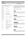
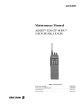
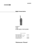
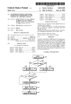
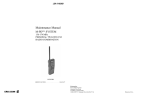
LBI-38432A
Mobile Communications
MTL-SX
146 - 174 MHz
PORTABLE TWO-WAY FM RADIO
TABLE OF CONTENTS
REAR COVER ASSEMBLY . . . . . . . . . . . . . . . . . LBI-38597
FRONT COVER ASSEMBLY (EARLIER) AND
CONTROL BOARD . . . . . . . . . . . . . . . . . . . . . . LBI-38514
FRONT COVER ASSEMBLY (LATER) LESS
CONTROL BOARD . . . . . . . . . . . . . . . . . . . . . . LBI-38834
SERVICE SECTION . . . . . . . . . . . . . . . . . . . . . . LBI-38515
Maintenance Manual
LBI-38432
TABLE OF CONTENTS
Page
SPECIFICATIONS ...............................................................................................................................
3
OPTIONS AND ACCESSORIES ........................................................................................................
4
INTRODUCTION ................................................................................................................................
FEATURES ....................................................................................................................................
5
5
DESCRIPTION.....................................................................................................................................
REAR COVER ASSEMBLY........................................................................................................
FRONT COVER ASSEMBLY .....................................................................................................
ANTENNAS ..................................................................................................................................
BATTERY PACKS ........................................................................................................................
UNIVERSAL DEVICE CONNECTOR.......................................................................................
6
6
6
6
6
7
PROGRAMMING ................................................................................................................................
FEATURES PROGRAMMABLE ON A PER CHANNEL BASIS............................................
FEATURES PROGRAMMABLE ON AN OVERALL RADIO BASIS ...................................
8
9
9
OPERATOR MANUAL ......................................................................................................................
9
OPERATING TIPS ...............................................................................................................................
9
INTRINSICALLY SAFE USAGE.......................................................................................................
BATTERY PACKS ........................................................................................................................
ACCESSORIES.............................................................................................................................
9
9
10
MAINTENANCE .................................................................................................................................
PREVENTIVE MAINTENANCE................................................................................................
10
10
ILLUSTRATIONS
Figure 1 - MTL-SX Portable Radio..............................................................................................
Figure 2 - UDC Pin-Out................................................................................................................
Figure 3 - Front Panel Parts ..........................................................................................................
Figure 4 - Rear Cover Assembly Block Diagram ........................................................................
Figure 5 - Front Cover Assembly Block Diagram.......................................................................
Table 1 - UDC Pin Functions......................................................................................................
7
8
11
12
13
8
NOTE
The software contained in this device is copyrighted by Ericsson GE Mobile Communications, Inc. Unpublished
rights are reserved under the copyright laws of the United States.
Copyright© June 1990, Ericsson GE Mobile Communications Inc.
2
LBI-38432
SPECIFICATIONS*
GENERAL
Frequency Ranges
146 - 162 MHz
157 - 174 MHz
FCC Type Acceptance Number
AXATR-182-B5 (146 - 162 MHz)
AXATR-182-C5 (157 - 174 MHz)
DOC Number
TR-182-D2
Channel Capacity
16
Frequency Stability
5.0 ppm
Channel Spacing
30 kHz
Operating Temperature Range
-30°C to +60°C
Maximum Relative Humidity
90% at 55°C
Battery Voltage
7.5 Vdc (nominal)
Dimensions (H x W x D)
less battery, knobs and antenna
with Extra High Cap. Battery
140 x 69 x 38 mm (5.52 x 2.72 x 1.50 ")
232 x 69 x 40 mm (9.15 x 2.72 x 1.58 ")
Weight
less battery and antenna
with Extra High Cap. Battery
540 grams (19 ounces)
907 grams (32 ounces)
TRANSMITTER
Rated RF Power Output
6.0 Watts
High / Low RF Power Output
6.0 Watts / 1 Watt (programmable on a per channel
basis)
Maximum FM Deviation
±5 kHz
FM Hum and Noise
-45 dB (companion receiver)
Spurious and Harmonic Emissions
-75 dBc
Audio Response
+1 to -3 dB (6 dB/octave pre-emphasis from
300 Hz to 3 kHz)
Audio Distortion
less than 3% (at 1000 Hz tone, ±3 kHz deviation)
RECEIVER
Sensitivity (12 dB SINAD)
-116 dBm (0.35 µV)
Adjacent Channel Selectivity
-80 dB
Critical Squelch
10 dB SINAD
Modulation Acceptance
±7 kHz
Intermodulation
-78 dB
Spurious and Image Rejection
-80 dB
Audio Output
500 mW (24-ohm load impedance)
Audio Response
+2 to -8 dB (6 dB/octave de-emphasis from
300 Hz to 3 kHz)
Audio Distortion
less than 5% (at 500 mW)
*
These specifications are intended primarily for the use of the serviceman. See the appropriate Specifications Sheet
for the complete specifications.
3
LBI-38432
OPTIONS AND ACCESSORIES
Radios, Antennas, Batteries
146-162
157-174
440-470
MHz
MHz
MHz
HELICAL
HELICAL
HELICAL
Carrying Accessories
ANTENNA PANC1C
ANTENNA PANC1D
ANTENNA PANC1F
BELT CLIP
PAHC1C
Swivel Mount Plate
5203
CARRYING CASE
WITH BELT LOOP
PAHC1E
PAHC1F
WITH SWIVEL MT
PAHC1G
PAHC1H
SHOULDER
STRAP
PAHC1K
Audio Accessories
HEADSET/MIC
PAAB1A
INTERFACE CONNECTOR
(Provided with PAAB1A)
EXTRA HIGH CAP. BATTERY
PAPA1F (INTRINSICALLY SAFE)
EXTRA HIGH CAP. BATTERY
PAPA1E
SPKR/MIC
PAAE1A
GE-STAR LANYARD
PAAC1B
HIGH CAPACITY BATTERY
PAPA1G (INTRINSICALLY SAFE)
HIGH CAPACITY BATTERY
PAPA1H
Chargers
MULTI-CHARGER
H2A2L2A 120 VAC 14 HR
H2A2J1A 120 VAC 1 HR
H2A2M2A 240 VAC 14 HR
H2A2N1A 240 VAC 1 HR
UNIVERSAL MULTI-CHARGER
CH6RA1 120 VAC 1HR
CH6SA1 120 VAC 14HR
CH6RA2 230 VAC 1HR
CH6SA2 230 VAC 14HR
4
UNIVERSAL DESK CHARGER
CH1RA1 120 VAC 1 HR
CH1SA1 120 VAC 14 HR
CH1RA2 230 VAC 1 HR
CH1SA2 230 VAC 14 HR
COMPACT CHARGER
H2A5C2A - Vehicular Charger
H2A6L2A - Desk Charger
VEHICULAR CHARGER
H2V01 - Vehicular Charger
H2V02 - Vehicular Chgr/Rptr Control
LBI-38432
standard EIA frequencies, can be programmed for
encoded/decoded operation.
INTRODUCTION
The Ericsson GE MTL-SX radio is a high-quality microprocessor-controlled synthesized portable FM radio. All
transmitter and receiver functions are controlled by the microprocessor-based circuitry.
The MTL-SX radio’s sturdy die-cast aluminum case has
rotary volume and channel controls on its top panel and three
(3) recessed push-buttons which provide scan control on its
front panel. A indicator light on the front panel lights when
the radio is transmitting and flashes when and the radio is
scanning. A recessed emergency button is located on the top
of the radio. All personality features are programmable with
the PC programming software.
•
•
•
•
FEATURES
•
•
•
•
•
•
•
16-Channel Capability - The preprogrammed
channels are selected with the top mounted rotary
Control Knob.
•
Scan Capability With User Selectable Scan List
- Using two (2) of the buttons on the front panel, the
operator can add and delete any the programmed
channels to the scan list. Priority-one and prioritytwo scan channels can also be selected. A thrid
button on this panel is used to toggle scan operation
on and off.
•
Volume Control Knob - This rotatable control
provides quick and easy adjustments to the volume
level. Minimum volume levels can be programmed
into the unit to prevent missed calls due to a low
volume setting.
Monitor Button - This side-mounted button is used
to disabled squelch and if programmed for the selected channel, it is used to toggle CG and/or T99
operation on and off.
•
•
•
Emergency Channel Feature - An emergency
channel can be programmed into the radio for GESTAR emergency signalling. GE-STAR emergency
signalling is activated by the recessed Emegency
Button on the top panel of the radio. GE-STAR can
also be activated by a lanyard connected to the UDC
(Universal Device Connector).
GE-STAR Compatibility - The radio can be programmed to transmit GE-STAR ID at PTT key, at
PTT unkey, or both. 16,384 individual ID codes are
available.
•
Programmable Multi-Tone Channel Guard
(CTCSS) - Channel Guard tone frequencies within
the range of 67 Hz to 210.7 Hz, including all of the
•
Programmable Multi-Code Digital Channel
Guard - Similar capability as with tone Channel
Guard is provided.
Two-Tone Sequential (T99) Decode - Selective
calling decode is enabled or disabled on each individual channel.
Channel Busy Lockout - Personality information
includes transmit disable capability on a channel
where carrier activity is present. This feature is
selectable on a per channel basis.
Programmable Carrier Control Timer - A programmable transmit timer will automatically disable the transmitter and provide an alerting tone
after time-out. This feature prevents radio damage
and unnecessary channel traffic in the event of a
"stuck" mic. The CCT is reset on every PTT.
Programmable Transmit Power Level - Transmitter power level is PC programmable into the radio
(high or low) on a per channel basis.
Squelch Tail Elimination - Squelch and audio circuits are designed so that annoying squelch pops
which may occur at the end of received messages
are minimized. This feature is compatible with existing STE systems.
Alert Tones - Alert tones prompt the operator of
various radio conditions such as channel access,
CCT time-out or a low battery.
Programmable Through The Universal Device
Connector (UDC) - The entire operation of the
radio can be field customized by programming the
unit using an IBM PC or compatible computer. The
programmed personality is stored in non-volatile
memory within the radio.
Simple Remote Control Capability - External accessories can be connected to the UDC such as a
headset, a speaker-mic or a lanyard. Connection of
the speaker-mic allows the operator to remotely
control PTT operation and audio level of the external speaker. An antenna jack is located on the UDC
for the connection of a remote mounted antenna
such as when the radio is used in a vehicular charger
or repeater.
Meets MIL-810C and D Specifications - The
sturdy die-cast aluminum case is designed to seal
out moisture, blowing rain and other harsh enviromental factors.
Battery Packs - Several different battery pack sizes
and capacities are available. Intrinsically safe battery packs are available for use in hazardous environments.
5
LBI-38432
•
Available Options - These options include the antennas, audio accessories, batteries, carrying accessories, chargers, lanyards, and the vehicular
charger/repeaters.
DESCRIPTION
The MTL-SX portable radio is consists of a two primary
assemblies. The Front Cover Assembly contains all of the
microprocessor circuitry, audio circuitry and the operating
controls. The Rear Cover Assembly houses the RF circuitry
which includes the transmitter, receiver and the frequency
synthesizer. The assemblies are electrically interconnected
by two single-in-line type connectors. When mated together,
the assemblies form a weather resistant die-cast aluminum
case that protects the radio’s circuitry from harsh outside
environments.
Power is provided by a battery pack that slides and locks
on to the bottom of the radio. The radio’s on/off switch is
located on the battery pack.
The antenna screws on to the top of the unit. A side
antenna connection is also provided at the UDC for an
external antenna or for test purposes. This UDC antenna
connection is also utilized for external antenna operation
when the radio is locked in the vehicular charger or repeater.
REAR COVER ASSEMBLY
The Rear Cover Assembly houses the RF Board in the
die-cast aluminum case. The complete assembly consists of
the VHF RF Board, aluminum case, top antenna jack, side
(UDC) antenna jack and various hardware.
The RF Board’s circuitry includes the transmitter, receiver and the frequency synthesizer. This FM circuitry is
under complete control of the microprocessor circuits. Controlling data sent to this assembly from the Control Board
includes serial synthesizer data loading, transmitter/receiver
enabling and a transmitter power level signal. The RF Board
outputs the demodulated audio and a synthesizer lock status
line to the Control Board. During transmitter operation, the
RF power appears at the top antenna jack (or the UDC jack
if the appropriate adapter plug is inserted). The Rear Cover
Assembly maintenance manual contains a detailed circuit
analysis, mechanical, outline and schematic diagrams for
this assembly.
FRONT COVER ASSEMBLY
The Front Cover Assembly houses all of the operating
controls and the digital control circuitry for the radio. The
Control Board is installed in the Front Cover Assembly and
6
flex circuits include the Keypad, UDC and Speaker Flex
circuits. The speaker, microphone and Battery Plate are also
a part of this assembly. The complete assembly is housed in
the die-cast aluminum front cover.
The Control Board located in the Front Cover Assembly
is the largest and most complex board in the Front Cover
Assembly. It contains all microcomputer and audio circuitry
which controls the radio. See the maintenance manuals specific to the Control Board or the Front Cover Assembly for
service information on the related assembly.
ANTENNAS
Antennas are selected base on the operating frequency
range of the radio. Antenna option PANC1C, part number
19B234804P2, is a 146 - 162 MHz (red bands) antenna and
antenna option PANC1D, part number 19B234804P3, is a
157 - 174 MHz (orange bands) antenna. Both of these antennas are helically-designed and mount in the antenna jack on
the top of the radio. An external antenna can be mounted to
the unit via the UDC. When an antenna is connected to the
UDC, the antenna on the top of the radio is disabled.
BATTERY PACKS
The battery pack connects to the bottom of the unit and
delivers a nominal 7.5 Volts dc to the radio. A recessed on/off
switch for the radio is located on the battery pack. An internal
fuse located in the radio’s Battery Plate protects the radio and
battery from excessive current draw. The battery packs are
available in several different capacities and sizes.
Radio contacts located on the top of the pack include
switched power, ground, the speaker enabling contacts and
a continuous power contact. In addition, four contacts are
located on the rear of the battery pack. These four contacts
provide connections to the slip-in type chargers or vehicular
chargers/repeaters while the battery pack is still connected
to the unit. The battery charging contacts are diode protected
from external shorts.
The chargers utilize an internal thermistor in the battery
pack to sense temperature and automatically control charge
rate of the battery. This allows for a maximum charge rate
without overheating the battery pack. All battery packs can
be charged in less than 1 1/2 hours with the rapid type
chargers. Nominal full charge time in a standard charger is
14 hours. The Service Section contains a detailed outline and
schematic diagram of a typical battery pack. Further service
information for the battery packs is also presented in the
Service Section.
Chargers are available with nominal charge times of one
hour (rapid) and fourteen hours (standard). Combinations
include single (1) and multi (5 or 6) position standard and
LBI-38432
SIDE VIEW
FRONT VIEW
Figure 1 - MTL-SX Portable Radio
rapid charge units. In addition, the vehicular chargers/repeaters simultaneously charge the battery while the radio is
operating.
The battery packs should be fully charged in an appropriate charger before they are placed into service. This applies to new battery packs received from the factory and to
battery packs that have been stored for long periods of time.
A fully charged battery pack should have an open-terminal
voltage greater than 7.5 Volts (typically 9.0 Vdc). The low
battery alert tone will sound when the battery pack needs
charging.
UNIVERSAL DEVICE CONNECTOR
The UDC is located on the side of radio just above the
PTT and Monitor Buttons. Various equipment such as the
audio accessories can be connected to the radio via the UDC.
The programming equipment is also connected to it when the
personality is programmed into the radio. The UDC furnishes an excellent first-check-point for initial bench checks
without the need to disassemble the radio. Table 2 lists all
pins and their appropriate function. When the radio is turned
on it senses the resistance value between UDC pins 9 and 1
and switches the appropriate circuits to provide proper radioto-accessory operation.
7
LBI-38432
PROGRAMMING
The radio’s personality is programmed using an IBM PC
or compatible computer. A full-screen portable PC can be
used for field programming. The Programming Manual and
Software is TQ-3339 and TQ-4339. TQ-3339 is supplied
with 5-1/4 inch floppy disks and TQ-4339 is supplied with
3-1/2 inch disks. This software uses a series of screens and
windows to guide you through a programming session. See
TQ-3339 or TQ-4339 for further programming details. PC
Programming Adapter TQ-3310 and Programming Cable
TQ-3311 will also be required. These items provide interface
and connection between the PC and the radio when the
personality is transferred from the PC into the radio.
NOTE
After programming or reprogramming the radio,
disconnect the programming cable an turn the radio
off and then back on. This action will take the radio
out of programming mode and restore normal operation.
Figure 2 - UDC Pin-Out
Table 1 - UDC Pin Functions
PIN
8
NAME
INPUT OR
OUTPUT
------
USE
1
GROUND
3
UDC RX AUDIO
Output
Test Point For Speaker Audio
4
SW BATT
Output
Switched Accessory Power
5
EXT PTT
Input
External Microphone PTT Input
6
TX DATA
Input
For Programming
7
RX DATA
Output
For Programming
8
SPARE
9
UDC VOLT
10
T/R
Output
Low = Transmit, High = Receive
11
UDC MUTE
Output
Low = Audio Muted
12
EXT MIC HI
Input
External Microphone Audio Input
13
EXT EMER
Input
Lanyard Connection
34
UDC DISCR
Output
------
Case Ground
Option/Accessory Sense Pin
Test Point For RX Audio
LBI-38432
FEATURES PROGRAMMABLE ON A PER
CHANNEL BASIS
•
•
•
•
•
•
•
•
•
•
•
Transmit and Receive Frequencies
Tone or Digital Channel Guard Encode/Decode
Type 99 Tone Decode Enabled or Disabled
Transmit Power Level High or Low
Battery condition is another critical factor in the trouble
free operation of a portable radio. Observe the procedures
listed in the Service Section to insure the battery packs do
not develop the "Memory Effect".
Transmit STE On or Off
Channel Busy Lockout Enabled or Disabled
Carrier Control Timer
Alert Tones On or Off
Switch Crystal Frequency Enabled or Disabled
GE-STAR Enabled or Disabled
GE-STAR sent with Channel Guard
FEATURES PROGRAMMABLE ON AN
OVERALL RADIO BASIS
•
•
•
•
•
•
In areas where transmission or reception is poor, some
improvement may be obtained by insuring that the antenna
is vertical. Moving a few yards in another direction or
moving to a higher elevation may also improve communication. Vehicular operation can be aided with the use of an
externally mounted antenna.
Minimum Volume Level
Power-Up Beep On or Off
GE-STAR And GE-STAR Emergency Options
Type 99 Tone Group Set
Scan with Channel Guard Enabled or Disabled
Priority-One Scan Channel is the Selected Channel,
Fixed Channel or Keypad Entered Channel
OPERATOR MANUAL
Complete operating details for the MTL-SX radio are
included in operator manual LBI-38431.
OPERATING TIPS
Always observe all of the Federal Communication Commission’s rules and regulations during any service or operating procedure.
INTRINSICALLY SAFE USAGE
Selected portable radios with appropriate factory installed F4 Options are certified as Intrinsically Safe by the
Factory Mutual Research Corporation. Intrinsically Safe approval includes Class I, II, III, Division 1 hazardous locations in the presence of Groups C, D, E, F and G
atmospheres. Non-Incendive approval includes Class I, Division 2 hazardous locations in the presence of Groups A, B,
C and D atmospheres.
Hazardous locations are defined in the National Electrical Code. Useful standards NFPA 437A and NFPA 437M for
the classifications of hazardous areas can be ordered from
the National Fire Protection Association, Batterymarch Park,
Quincy, MA 02269.
BATTERY PACKS
Only battery packs identified with a green latch shall be
used with a portable radio that is rated and labeled as Factory
Mutual Intrinsically Safe. Use of non-specified battery packs
voids Factory Mutual approval. The following battery pack
options are approved for use in intrinsically safe radios:
PAPA1F
(19A704860P6)
Rechargeable Battery Pack,
Extra High Capacity (Tall Case)
PAPA1G
(19A704850P6)
Rechargeable Battery Pack,
High Capacity (Short Case)
Antenna location and condition is important when using
a VHF radio. Operating the radio in low areas of terrain,
under power lines or bridges, inside of a vehicle or in a metal
or steel framed building can severely reduce the range of the
unit. Mountains and buildings can also reduce the range of
the unit.
9
LBI-38432
ACCESSORIES
MAINTENANCE
The accessories that follow are approved for use with
intrinsically safe radios. Use of accessories other than those
listed voids Factory Mutual approval.
The MTL-SX radio is a very reliable unit and will
normally provide many years of trouble-free service. The
recommended Preventive Maintenance procedures that follow should be preformed when a technician comes in contact
with a unit. Component level troubleshooting information is
contained in the Service Section.
PAAB1A
(19B801508P3)
Headset/Microphone
PAAC1A
(19B801508P2)
Earpiece Kit
PAAC1B
(19B801508P8)
GE-STAR Lanyard
PAAE1A
(19B801508P1)
Speaker/Microphone
PAAE1B
(19B801508P4)
Speaker/Microphone with
GE-STAR Lanyard
PAAE1C
(19B801508P6)
Speaker/Microphone/Antenna
Battery Packs
PANC1C
(19B234804P2)
Antenna, 146 - 162 MHz, Helical
Insure the battery packs are properly maintained. Do not
over or under charge them on a regular basis. Verify the
contacts are clean and free of corrosion.
PANC1D
(19B234804P3)
Antenna, 157 - 174 MHz, Helical
PAHC1C
Belt Clip
PAHC1D
Swivel Mount with Belt Loop
Since portable radio units are subject to shock and
vibration, check for loose plugs, knobs, screws, etc.
PAHC1E
Case, Leather, with Belt Loop
(Short Case)
Transmitter Check
PREVENTIVE MAINTENANCE
Antenna
The antenna and antenna contact should be kept clean
and free from dirt or corrosion. If the antenna contact should
become dirty or corroded, communication range could be
reduced.
Mechanical
PAHC1F
Case, Leather, with Belt Loop
(Tall Case)
PAHC1G
Case, Leather, with Swivel Mount
and Belt Loop (Short Case)
PAHC1H
Case, Leather, with Swivel Mount
and Belt Loop (Tall Case)
Receiver Check
PAHC1K
Shoulder Strap, Leather, with
Mounting Plate
Receiver sensitivity should be checked periodically as
an indication of overall receiver operation.
PAHC1N
Holster, Plastic.
Check transmit frequency and deviation. Normally
these checks are made when the unit is first put into operation. They should be repeated after the first month of operation, then annually.
Cleaning
If the unit requires an external cleaning use mild soap
and a damp cloth. Avoid abrasive cleaners or chemicals
which may damage the plastic or rubber surfaces on the unit.
10
LBI-38432
(19D438678, Sh. 3, Rev. 8)
Figure 3 - Front Panel Parts
Printed in U.S.A.
11
LBI-38432
BLOCK DIAGRAM
Figure 4 - Rear Cover Assembly Block Diagram
12
BLOCK DIAGRAM
LBI-38432
Figure 5 - Front Cover Assembly Block Diagram
13