1
US005815820A
Ulllted States Patent [19]
[11] Patent Number:
Kiem et al.
[45]
[54]
TRANSMITTER HAVING ADJUSTABLE
POWER LEVELS RESPONSIVE TO THE
POSITION OFA MOVABLE ANTENNA
.
[75]
-
-
.
-
Inventors‘ {,0ilxiirgkfiggggfllinlliggiinM?chael
5,109,538
5,109,539
5,138,329
4/1992 Ikonen et al. ..
4/1992 Inubushi et al. ..
8/1992 Saarnimo et al.
1
[22]
A
pp
5,144,324
9/1992 Chin et al. ...... ..
1/1993
5,541,609
7/1996 StutZman et al. ..................... .. 455/575
Filed:
Miyake
. .... ... .
455/127 X
. . . . ..
455/126
@
Motorola, Inc., User Manual ( 1991) 68P09357A20—0, for
a Cellular mobile telephone
An FCC application (dated Feb. 19, 1992) and grant (dated
l. N .._ 880 918
0
.... .. 455/126
...... .. 455/89
.... .. 343/702
OTHER PUBLICATIONS
[73] Assignee: Motorola, Inc., Schaumburg, Ill.
21
Sep. 29, 1998
5,179,353
Kaschke, Hoffman Estates; Raymond
A. J enski, Palatine, all of Ill.
[
Date of Patent:
5,815,820
Mar. 18 ’ 1992) for equipment authorization (FCC ID:
AXATR—208—AZ).
’
May 11, 1992
EIA Standard, Cellular System Mobile Station—Land STa
tion Comaptibility Speci?cation, IS—3—D, Mar. 1989.
Related US. Application Data
[63]
Continuation-in-part of Ser. No. 729,502, Jul. 12, 1991.
Primary Examiner—EdWard F. Urban
Attorney, Agent) Or Firm—KeVin D- Kaschke
[51]
Int. Cl.6 ..................................................... .. H04B 1/38
[57]
gfsl'dclt', """
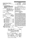
A portable radiotelephone (200) adjusts its transmit poWer
[
]
1e
0
e21;
""""""" " 455/575;
333/
""""""""""""""""" " _
/
’
’
’
4 /83’ 126’ 128’ 129’ 127’ 343/702’ 901
.
[56]
ABSTRACT
responsive to the position of a movable antenna (213). The
antenna (213) is movable betWeen a retracted (313) and an
extended position (314). The portable radiotelephone (200)
References Clted
U,S, PATENT DOCUMENTS
_
gggglhiergal' "
.......
transmits at loW poWer When the antenna (213) is retracted
and at high poWer When the antenna (213) is extended.
Additionally, the portable radiotelephone (200) can notify a
remote base station of the change in transmit poWer at any
4,914,714
4/1990
Tamura
4,958,782
9/1990
Imanishi
. . . . .. 455/89 X
5,048,117
9/1991 Aisaka et a1. ........................... .. 455/89
... ... ... .
. . . . ..
“me dunng transmlsslon'
455/73
22 Claims, 13 Drawing Sheets
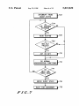
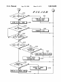
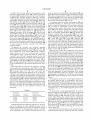
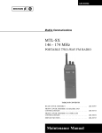
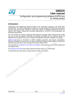
- ENTER
TRANSMIT - ROUTINE
IS
ANTENNA OEXTENDED
1405
1407
\
/
SET MAX. POWER A1 1214
SET NAx. POWER AT o.sw
AND CLASS = 2
AND CLASS = 3
4
IS
CALL IN QPROGRESS
ACTIVATE TRANSMITTER
1409
NOTIFY THE EASE
STATION OF THE CLASS
,- 1411
l
NORMAL
TRANSMITTER PROCESSING
U.S. Patent
Sep.29,1998
Sheet 1 0f 13
5,815,820
FIG.2
FIG.1
U.S. Patent
F[G.3A
Sep.29,1998
Sheet 2 0f 13
5,815,820
U.S. Patent
Sep.29,1998
AV'ldSIG
Sheet 4 0f 13
5,815,820
U.S. Patent
Sep. 29, 1998
5,815,820
Sheet 6 0f 13
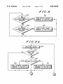
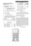
INTERRUPT FROM
SLEEP STATE
702
IS
THE ANTENNA
EXTEONDED
READ KEYPAD
ACT 0N KEY
7 1O
DO NORMAL
HOUSEKEEPING FUNCTIONS
712
N0
G0
INTO LOW
POWER? MODE
ENTER SLEEP STATE
|--716
WAIT FOR INTERRUPT r718
F[G.7
U.S. Patent
Sep.29,1998
Sheet 7 0f 13
5,815,820
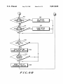
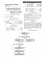
F]G'.8
802
804
)
WAS
AN ANTENNA
RETRACTED INDICATION
RECEIVED
'?
COMMAND TO MASTER ,u,P
806
WAS
AN ANTENNA
EXTENDED INDICATION
808
T
SEND KEYPAD ENABLE
SEND KEYPAD DISABLE
COMMAND TO MASTER ,u,P
RECEQIVED
F]G’..9A
T
READ HKS STATE
910
I
SEND EXTENDED ANTENNA
COMMAND TO MASTER ,uP
'
SEND RETRACTED ANTENNA
COMMAND TO MASTER ,u,P
U.S. Patent
Sep.29,1998
Sheet 8 0f 13
$316
SET KEYPAD
ENABLE FLAG
918
I
CLEAR KEYPAD
ENABLE FLAG
READ KEYPAD AND
VOLUME CONTROL SWITCHES
922
NORMAL SLAVE [1P
BACKGROUND FUNCTION
926
FIGZQBI
5,815,820
Q3
U.S. Patent
Sep.29,1998
RESET
Sheet 9 0f 13
5,815,820
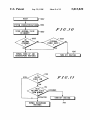
I» 1002
SYSTEM CHARACTERIZATION F1004
F f G’ . I 0
STORE ANTENNA STATE
IN MEMORY
1005
V
I HOUSEKEEPING
NORMAL WAKE-UP
AND I
ROUTINES
T
_
|
HIGH
19 1 0
TURN OFF ROUTINE
FIG. II
READ
ANTENNA STATE
FROM MEMORY
RETRACTED
|
TURN-OFF ROUTINE
NORMAL BACKGROUND
ROUTINES
1116
-
I
I
U.S. Patent
Sep.29,1998
NORMAL RADIO
NICROCOMPUTER
BACKGROUND FUNCTION
Sheet 10 0f 13
5,815,820
1202
TO OFF HOOK
SWITCH TRANSITION
N0
ACTIVATE VOICE
RECOGNITION
ACTIVATE KEYPAD
BACKLIGHT AND DISPLAY;
TIME FOR 6 SECS;
DEACTIVATE KEYPAD
BACKLIGHT AND DISPLAY
1234
1235
1238
I
DEACTIVATE
MUTE FUNCTION
TURN OFF VOICE
RECOGNITION, BACKLIGHT
AND DISPLAY
m” FIG’JZA @
U.S. Patent
Sep.29,1998
Sheet 11 0f 13
5,815,820
F I G’ . I 2 B
YES
MUTE FUNOCTION ON
GD
1214
TURN OFF VOICE
RECOGNITION
START N MSEC. TIMER
1216
HAS
TIME EXPIRED
YES
1222
1220
)
I
TERMINATE CALL
ON
TO OFF HOOK
'
A
SWITCH TRANSITION
1224
VOICE
RECOGNITION
ACTIXATED
1228
H’
CURRENTLY
IN HANBS FREE
SWITCH TO HANDS
FREE MODE
U.S. Patent
Sep.29,1998
Sheet 12 0f 13
5,815,820
U.S. Patent
Sep.29,1998
Sheet 13 0f 13
5,815,820
1407
1
SET MAX. POWER AT 0.6W
AND CLASS = 3
CALL IN QPROGRESS
ACTIVATE TRANSMITTER
1409
NOTIFY THE BASE
1411
STATION OF THE CLASS
NORMAL
1412
TRANSMITTER PROCESSING
v
FIGJ4
5,815,820
1
2
TRANSMITTER HAVING ADJUSTABLE
body, and more particularly, the human head is biologically
POWER LEVELS RESPONSIVE TO THE
POSITION OF A MOVABLE ANTENNA
sensitive to excessive levels of radiated energy. The level of
exposure of the human body to the radiated energy is related
at least in part to the poWer level of the transmitted signal
and the distance betWeen the antenna and the human body.
Exposure increases With increasing poWer level or decreas
RELATED APPLICATIONS
The present application is a Continuation in Part of patent
ing distance.
Portable radiotelephones, by design, are held against the
application Ser. No. 07/729,502, entitled “Apparatus and
Method for Generating a Control Signal Responsive to a
Movable Antenna”, ?led on Jul. 12, 1991 by Kevin D.
Kaschke and assigned to the assignee of the present inven
user’s head so that the user may conveniently listen via an
10
tion.
FIELD OF THE INVENTION
The present invention relates generally to portable com
munication devices, and more particularly to a portable
Safety standards have been established by the US. govern
15
transmitting device having adjustable transmit poWer levels
responsive to the position of a movable antenna.
BACKGROUND OF THE INVENTION
A portable communication device, of Which a portable
earpiece speaker and talk via a microphone. Such a design
results in the antenna being located near the user’s head, thus
unavoidably exposing the user’s head to the radiated energy.
20
cellular radiotelephone subscriber unit is a convenient
ment to safely limit the exposure of humans to the radiated
energy. The safety standards have been more than met by
limiting the poWer level of the transmitted signal.
HoWever, a consequence of limiting the portable radio
telephone’s transmit poWer is that the physical distance from
Which the portable radiotelephone may transmit a signal to
a remote base station is limited. Thus, limiting the portable
example, provides an appropriate setting for describing the
radiotelephone’s transmitter poWer to meet the safety stan
dards also limits the useful transmit range of the portable
need for the present invention. The small siZe of portable
radiotelephone.
radiotelephones enables the user to carry and store the unit
virtually anyWhere.
25
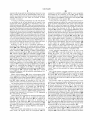
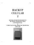
Such portability is afforded by the use of a foldable
housing and a movable antenna. FIG. 1 shoWs a foldable
portable radiotelephone 100 having a housing portion 101
hinged to a body portion 103 and an antenna 109 extendably
retractable along its longitudinal axis. For increased port
ability When the portable radiotelephone 100 is not in use,
the hinged housing portion 101 is rotated to cover the
keypad 105 and the antenna is retracted substantially inside
to the body of the portable radiotelephone. A retracted
antenna can transmit and/or receive radio frequency (RF)
Accordingly, there is also a need for a transmitting device,
of Which a cellular portable radiotelephone is merely an
example, that can transmit RF signals at a higher poWer level
While limiting the exposure of humans to energy radiated by
the transmitter’s antenna.
A portable radiotelephone comprises antenna means
30
including an antenna element, and a transmitter. The antenna
element is moveable betWeen a stoWed position and an
unstoWed position. The transmitter transmits a signal from
the antenna means at a ?rst poWer level When the antenna
35
element is moved to the stoWed position and at a second
poWer level, greater than the ?rst poWer level, When the
signals but the antenna’s performance is less than an
extended antenna because of its shortened electrical length
and interference from the close proximity of the user’s body.
antenna element is moved to the unstoWed position.
BRIEF DESCRIPTION OF THE DRAWINGS
To use the portable radiotelephone, the hinged housing
FIG. 1 is an isometric draWing of a portable radiotele
portion 101 is rotated to expose the keypad 105 and the
antenna is extended to project aWay from the body of the
phone having a hinged housing portion Which may employ
the present invention.
portable radiotelephone for better performance.
This portability, hoWever, alloWs the portable radiotele
phone to be placed in locations Where foreign objects may
FIG. 2 is an isometric draWing of a portable radiotele
phone Without a hinged housing portion Which may employ
45
the present invention.
come in contact With a user interface mechanism (i.e. a
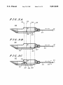
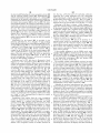
FIGS. 3A—3C are side vieWs of the portable radiotele
keypad) and inadvertently enable or disable control func
tions of the radiotelephone. Such undesirable actuation of
the control functions is likely to engage related functions
Which reduce the operating life of a storage battery Which
poWers the portable radiotelephone and may inhibit normal
phone of FIG. 2 having a cut-aWay vieW shoWing a ?rst,
second, and third embodiment, respectively, of the the
radiotelephone of FIG. 2.
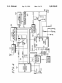
FIG. 4 is a block diagram of the electronic elements of the
portable radiotelephone of FIG. 2 embodying the present
operation.
invention.
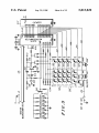
FIG. 5 is a schematic diagram of a slave microcomputer
US. Pat. No. 4,845,772 and US. patent applications Ser.
Nos. 07/439,993 and 07/439,983 describe portable radio
telephones that enable or disable control functions of the
radiotelephone responsive to the position of the hinged
housing portion. Steps have been taken, hoWever, to reduce
the cost, Weight and thickness of the portable radiotelephone
by eliminating the hinged housing portion. In doing so, the
advantages of controlling functions of the portable radio
telephone responsive to the hinged housing portion are lost.
55
and associated circuitry employed in the portable radiotele
phone of FIG. 4.
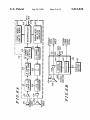
FIGS. 6A and 6B are block diagrams of voice recognition
circuitry and vehicular adaptor (hands-free) circuitry,
respectively, employed in FIG. 4.
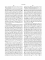
FIG. 7 is a ?oWchart depicting the deactivation process
60
employed in the slave microcomputer of FIG. 5.
Accordingly, there is a need for a portable communication
FIG. 8 is a ?oWchart depicting the process of activation/
device, of Which a cellular portable radiotelephone is merely
deactivation employed in the master microcomputer of FIG.
an example, having functions that can be controlled Without
the use of a hinged housing portion.
Portable radiotelephone antennas radiate RF electromag
netic energy While transmitting an RF signal. The human
4.
65
FIGS. 9A and 9B, combined, are ?oWcharts depicting the
process of activation/deactivation employed in the slave
microcomputer of FIG. 5.
5,815,820
3
4
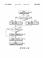
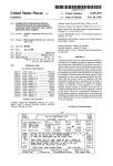
FIG. 10 is a ?owchart depicting the process of activation/
deactivation of the power on/off sWitch upon initial poWer
up of the master microcomputer of FIG. 4.
FIG. 11 is a ?oWchart depicting the process of activation/
deactivation of the poWer on/off sWitch after initial poWer-up
of the master microcomputer of FIG. 4.
FIGS. 12A and 12B are a ?oWchart depicting the process
313—316, respectively. The ?rst position at 313 represents
of interpreting hooksWitch operation of the master micro
computer of FIG. 4.
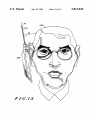
FIG. 13 is a draWing shoWing the change in distance
the position of a retracted antenna. The second position at
314 represents the position of an extended antenna. The third
position at 315 represents the position of a retracted antenna
further retracted into the radiotelephone 200 than the ?rst
position at 313. The fourth position at 316 represents the
position of the antenna betWeen the ?rst and the second
position, for example, approximately half Way betWeen the
retracted position at 313 and the extended position at 314 of
10
betWeen an antenna of a portable radiotelephone and a user’s
head When the antenna is retracted and extended.
accordance With the present invention is described in US.
Pat. No. 4,121,218. The movable antenna comprises a
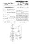
FIG. 14 is a ?oWchart depicting a change the transmit
poWer of a portable radiotelephone responsive to the radio
telephone’s antenna position.
15
DETAILED DESCRIPTION OF A PREFERRED
EMBODIMENT
A portable radiotelephone 200 adapted for use in a
cellular radiotelephone system is shoWn in FIG. 2. The user
may listen via the earpiece 201 and may speak into the
microphone 203. The keypad 205 consists of a plurality of
buttons numbered one through Zero, # and * in a familiar
telephone arrangement as Well as additional function buttons
25
such as “send”, “end”, “clear”, “function”, “on/off” and
other buttons associated With memory recall. Disposed on a
side of the portable radiotelephone are tWo volume control
buttons: volume increase 207 and volume decrease 209,
Which may adjust the volume of the earpiece and/or the
stationary helical coil capacitively coupled to an extendable
half-Wavelength radiator. The radio transmits primarily from
the stationary helical coil When the half-Wavelength radiator
is retracted and primarily from the half-Wavelength radiator
When the half-Wavelength radiator is extended.
The preferred embodiments 325—327 utiliZe conventional
reed sWitches 305 and 307 electrically coupled to a printed
circuit board 303 and a magnet 301 af?xed to an end portion
of the antenna 213 inside the radiotelephone 200. A mag
netic ?eld given off by the magnet 301 causes the reed
sWitches 305 or 307 to close, i.e., short circuit, When placed
in close proximity to one of the reed sWitches and to open
circuit When displaced from one of the reed sWitches. The
reed sWitches 305 and 307 are coupled to the radiotelephone
circuitry Which takes appropriate action responsive to the
open or closed state of the reed sWitches 305 or 307.
Referring noW to FIG. 3A one may appreciate the advan
ringer. A display 211, disposed above the keypad 205,
provides visual feedback for the buttons depressed and other
operational features. AWireless communication element, for
example antenna 213, provides Wireless transceiving com
munications betWeen the the portable radiotelephone 200
and the cellular radiotelephone system. To reduce the cost,
the antenna 213.
An example of a movable antenna that may be used in
35
Weight and thickness of the portable radiotelephone 200, the
hinged housing portion 101 used by the portable radiotele
phone 100 of FIG. 1 is not attached to the radiotelephone
200 of FIG. 2.
tages of the ?rst preferred embodiment of the present
invention Wherein a hooksWitch control signal (at line 511 in
FIG. 5) is generated responsive to the antenna’s position.
Once a typical portable radiotelephone is turned “on” by
conventionally depressing the “on/off” key on the keypad
205, ansWering, terminating or readying a telephone call
requires a key depression or rotating the aforementioned
hinged housing portion to generate the hooksWitch control
signal. Additionally, the antenna is typically extended during
As in typical Wireless communication devices, the
antenna 213 is extended When the portable radiotelephone
200 is in use and retracted When the portable radiotelephone
use for optimal Wireless communication performance and
200 is not in use. HoWever, in addition to positioning the
sWitch control signal at line 511 of FIG. 5 is generated
responsive to the position of the antenna 213 relative to the
radiotelephone’s antenna 213 for transceiving communica
tion signals, a novel feature of the radiotelephone 200
comprises controlling a predetermined operating mode of
the radiotelephone 200 responsive to the antenna’s position
While providing for the advantage of reduced cost, Weight
and thickness. The predetermined operating mode is a
particular functioning arrangement or condition of the radio
telephone including but not limited to the radiotelephone’s
retracted When not in use.
In the ?rst preferred embodiment, hoWever, the hook
45
portable radiotelephone 325. Thus the key depression or
rotation of the hinged housing portion to generate the
hooksWitch control signal at line 511 of FIG. 5 is eliminated.
This feature of the radiotelephone 325 provides the user
greater convenience in operating the radiotelephone. The
user may ansWer a telephone call by simply extending the
antenna 213.
200 poWer on or off state, voice recognition’s on or off state,
Extending the antenna 213 may also ready the portable
functions implemented responsive to a key depression, or
radiotelephone to make a call. Such a state of ansWering or
55 readiness to make a call is commonly knoW as “off-hook”.
transmit poWer.
FIGS. 3A—3C illustrate a side vieW of a ?rst 325, second
To make a call, the user enters the appropriate phone number
through the keypad and depresses the “send” button to
326 and third 327 embodiment, respectively, of the portable
radiotelephone 200 of FIG. 2. A cut-aWay portion exposing
activate the portable radiotelephone’s transmitter thereby
initiating communication With the cellular radiotelephone
system. In the ?rst preferred embodiment, the “send” key
a cross sectional vieW in FIGS. 3A—3C illustrate unique
sWitching mechanisms for implementing alternatives of the
present invention. In the preferred embodiments 325—327
the antenna 213 may be perceived to extend (solid line)
substantially outside the radiotelephone 200 or retract
513 (FIG. 5) may also be used to ansWer a telephone call if
the antenna is already extended. The user may terminate the
telephone call by retracting the antenna 213. Such a retracted
(dotted line) substantially inside the radiotelephone 200
along a center axis 311 of the antenna 213. A ?rst, second,
third and fourth position of the antenna 213 inside the
radiotelephone 200 are referenced to datum lines at
state of the antenna is commonly knoWn as “on-hook”. In
65
the ?rst preferred embodiment, the “end” key 515 (FIG. 5)
may also be used to terminate a telephone call if the antenna
is already extended.
5,815,820
5
6
In FIG. 3A, one may perceive the generation of the
hooksWitch control signal at line 511 of FIG. 5 responsive
the antenna 213 being moved betWeen the retracted position
at 313 and the extended position at 314. An “on-hook”
control signal is generated When the antenna 213 is retracted
mode of operation of the portable radiotelephone 325 may
be disabled to prevent accidental operation When the antenna
213 is in its retracted position at 313, i.e., When the portable
radiotelephone 325 is not in use, and may be enabled When
the antenna 213 is in its extended position at 314, i.e., When
the portable radiotelephone 325 is in use.
substantially inside the portable radiotelephone 325 to the
?rst position at 313 such that the magnet 301 on the end
portion of the antenna 213 is in close proximity With the reed
For example, When the portable radiotelephone 325 is in
sWitch 305. The magnetic ?eld given off by the magnet 301
causes the reed sWitch 305 to short circuit thereby placing
the radiotelephone 325 in the “on-hook” state. Extending the
10
described foreign object inadvertently turn the radiotele
antenna 213 substantially outside the portable radiotele
phone 325 to the second position at 314 displaces the
magnetic ?eld given off by the magnet 301 from the reed
sWitch 305 causing the reed sWitch 305 to open circuit
phone 325 off or initiate a battery poWer draining function
such as a key depression. Therefore, retracting the antenna
213 on the portable radiotelephone 200 may disable user
15
placing thereby placing radiotelephone 325 in the “off
a retracted antenna at 313 may disable circuitry such as
voice recognition circuitry as shoWn in FIG. 6A and hands
free circuitry as shoWn in FIG. 6B. Extending the antenna
213 enables the aforementioned disabled control functions
and circuitry as Well as keypad illumination 536—541 and
operating modes.
To generate the “on-hook” and “off-hook” operating
25
also conventionally depress the “end” 515 and “send” 513
keys, respectively, on the keypad 205. Similar radiotele
phone devices, such as conventional cordless
Referring noW to FIG. 3B, an illustration of the second
35
erable.
Table 1 describes the “on-hook” and “off-hook” operating
modes produced by actuating the “send” 513 or “end” 515
keys or by moving the antenna 213 after the radiotelephone
325 is already turned “on”. The “end” and “send” key
depression may place the radiotelephone in an “on-hook” or
“off-hook” state, respectively. The antenna position may be
extended (out) outside the radiotelephone, or retracted (in)
Within the radiotelephone. Extending the antenna 213 places
the radiotelephone 325 “off-hook” regardless of Whether the
display circuitry 211‘ per FIG. 5.
preferred embodiment, one may perceive the generation of
the on/off poWer control signal responsive to the antenna
position. In the second preferred embodiment, the user need
only extend the antenna 213 and the portable radiotelephone
326 automatically turns “on” thus eliminating both of the
radiotelephones, have a dedicated sWitch to produce the
“on-hook” and “off-hook” operating modes. In the ?rst
preferred embodiment, the “on-hook” and “off-hook” oper
ating modes are produced by actuating the “send” 513 or
“end” 515 keys on the keypad 205 or by moving the antenna
213 to provide optimum user convenience and functionality
for the radiotelephone if the antenna should become inop
interface controls, either on the keypad 205 or on other
peripheral surfaces of the radiotelephone 325, such as the
“on/off” 508, number dialling 517, volume controls 207‘ and
209‘, “send” 513, “end” 515, “clear” 521, “function” 523
and memory store 525 and recall 527 controls. Additionally,
hook” state. In the ?rst preferred embodiment, the combi
nation of the magnet 301 and the reed sWitch 305 coupled to
the printed circuit board 303 may be knoWn as the hook
sWitch. In the ?rst preferred embodiment, the antenna 213
has at least tWo positions relative to the radiotelephone 325
in order to generate both the “on-hook” and “off-hook”
modes Without positioning the antenna 213, the user may
its standby condition, i.e., turned “on” but in a loW poWer
mode to conserve battery poWer While aWaiting a telephone
call, it Would be undesirable to have the previously
previously described typical steps of opening the hinged
housing portion and depressing the “on/off” key 508 (FIG.
5). LikeWise, to turn “off” the portable radiotelephone 326,
the user need only retract the antenna 213 again eliminating
both of the previously described typical steps of depressing
the “on/off” key 508 and closing the hinged housing portion.
In the second preferred embodiment, the “on-hook” and
“off-hook” operating modes are generated using a conven
tional key depression. A further advantage of the second
preferred embodiment alloWs the designer of the portable
radiotelephone to eliminate the “on/off” key on the keypad
205 completely thus reducing the cost and surface area of the
45
radiotelephone 325 Was placed in the “on-hook” or “off
keypad.
Generating the on/off poWer control signal responsive to
the antenna position may be conveniently used With a
hook” by a key depression. Similarly, retracting the antenna
second-generation cordless telephone service called CT-2.
One feature of the CT-2 cordless telephone is that it Will only
213 places the radiotelephone 325 in the “on-hook” state
regardless of Whether the radiotelephone 325 Was placed in
alloW outgoing calls. Therefore, the user should not have a
need to extend the antenna Without the intention of making
the “on-hook” state or in the “off-hook” state by a key
depression.
a telephone call, i.e., the cordless telephone must be poW
ered “on”.
TABLE 1
HooksWitch
An on/off poWer control signal 412 (FIG. 4 and 5) is
HooksWitch
state after the
Antenna
state after the
key depression.
movement.
antenna movement.
on-hook
off-hook
on-hook
off-hook
in to out
in to out
out to in
out to in
off-hook
off-hook
on-hook
on-hook
Determining the hooksWitch state responsive to the posi
tion of the antenna not only simpli?es operation of the
portable radiotelephone for the user but also alloWs certain
control functions to be advantageously enabled or disabled
at the appropriate time. Control functions related to the
55
generated When the antenna 213 is moved from its retracted
position at 313, past the half Way position at 316 to its
extended position at 314. Generation of the on/off poWer
control signal 412 in the second preferred embodiment
occurs When magnet 301 momentarily short circuits the reed
sWitch 307 at the half Way position at 316. As the antenna
213 passes the half Way position at 316, the magnetic ?eld
given off by the magnet 301 comes in close proximity With
the reed sWitch 307 causing the reed sWitch 307 to momen
65
tarily short circuit thereby generating the on/off poWer
control signal 412.
The movement of the antenna from the retracted position
at 313 through the half Way position at 316 to the extended
5,815,820
7
8
position at 314 causes the reed switch 307 to be momentarily
turn the radiotelephone “on”. The movement of the antenna
antenna inside the radiotelephone presses against a spring
319 of nonmagnetic material generating a spring force
against the end of the antenna 213 along the antenna axis
from the extended position at 314 past the half Way position
311. One end of the spring 319 is attached to a support 321
at 316 to the retracted position at 313 causes the reed sWitch
to ?xture the spring 319. The other end of the spring 319,
opposite the support 321, extends into free space and may be
forced upon by the antenna 213.
The force applied by the user overcomes the opposite
force returned by the spring 319 so that the magnet 301
actuated producing the on/off poWer control signal 412 to
307 to be momentarily short circuited producing the on/off
poWer control signal 412 to turn the radiotelephone “off”
A logic interface circuit in a poWer controller 410 (FIG.
4) detects the momentary reed sWitch closure and initiates
the steps to turn the portable radiotelephone 326 “on” if
previously “off” or “off” if previously “on”. Details describ
ing the logic interface circuit may be referenced in Us. Pat.
10
sWitch 307. The spring 319 completely collapses When the
No. 4,798,975 entitled “High Noise Immunity Input Level
Detector With Hysteresis”, ?led in behalf of WalcZak et. al.
and assigned to the assignee of the present invention. Other
logic interface circuits may also be used to detect the
momentary reed sWitch closure.
To conventionally turn “on” or “off” the portable radio
telephone 326 Without positioning the antenna 213, the user
may also depress the “on/off” key 508 on the keypad 205. In
a ?rst alternative to the second preferred embodiment of the
present invention, the depression of the “on/off” key 508 or
moving the antenna 213 may generate the on/off control
signal 412 to provide optimum user convenience and func
tionality for the radiotelephone if the antenna should become
15
end portion of the antenna, the spring 319 forces the antenna
sWitch 305 to become a short circuit. The antenna may then
be positioned to the extended position at 314 or the retracted
position at 313 to generate the “off-hook” or “on-hook”
25
314 positions. Thus, the radiotelephone may not be unin
tentionally turned “on” or “off” When positioning the
closed sWitch to determine the on/off poWer operating mode.
antenna to generate the hooksWitch signal 511 and may be
inhibited from accidental actuation of the on/off control
For example, cordless radiotelephones do not use a momen
signal 412 produced by positioning the antenna at position
35
the present invention by positioning the reed sWitch 307 at
315.
The third preferred embodiment includes the advantages
of both the aforementioned ?rst and the second preferred
embodiments. The on/off and hooksWitch control signals
generated by the antenna may also be generated by a key
depression giving the user optimal convenience and radio
telephone functionality if the antenna 213 should become
one extreme of the antenna movement. In FIG. 3B the
alternative position for the reed sWitch 307‘ is shoWn at
position 314. Thus, When the antenna 213 is retracted to 313,
the reed sWitch 307‘ is open and the radiotelephone 326 is in
the “off” operating mode. LikeWise, When the antenna is
extended to 314, the reed sWitch 307‘ is closed and the
inoperable.
An alternative to generating the on/off control signal
described in the third preferred embodiment comprises
radiotelephone 326 is in the “on” operating mode.
Referring noW to FIG. 3C, an illustration of the third
states, respectively. The force required by the user to posi
tion the antenna in the third position at 315 by compressing
the spring 319 is substantially greater than the force required
to move the antenna betWeen the retracted 313 and extended
In a second alternative of the second preferred embodi
ment the radiotelephone 326 utiliZes a continuously open or
“on” or “off” mode of a cordless radiotelephone may utiliZe
magnet 301 is closest to the reed sWitch 307 so that the
magnet does not move past the reed sWitch 307.
Consequently, the reed sWitch 305 becomes an open circuit
and the reed sWitch 307 becomes a closed circuit.
When the user releases the applied force on the exposed
213 to its normally retracted position at 313 Which causes
reed sWitch 307 to become an open circuit and the reed
inoperable.
tary on/off poWer sWitch. Conventional cordless radiotele
phones have a slide sWitch Which places the radiotelephone
in the “on” mode When short circuited and places the
radiotelephone in the “off” mode When open circuited. The
moves from its position at 313 in proximity to the reed
sWitch 305 to the position at 315 in proximity to the reed
45
spinning the antenna 213 about the axis 311 of the antenna
213 as shoWn at 323 instead of depressing the antenna to the
preferred embodiment, one may perceive the generation of
third position at 315. Conventional sWitching mechanisms
both the hooksWitch 511 and the on/off poWer control 412
responsive to a spinning motion about an axis are Well knoW
signals responsive to the antenna position. Depressing the
to those skilled in the art and may be employed in this
alternative. Axial displacement of the antenna betWeen the
“on/off” key 508 on the keypad 205 to generate a poWer
control signal 412 and the “send” 513 or “end” 515 key on
the keypad 205‘ to produce the hooksWitch operating mode
are combined With the antenna movement to provide opti
mum user convenience and radiotelephone functionality
should the antenna become inoperable. In the third preferred
embodiment, the antenna 213 has at least three positions.
55
retracted and extended positions at 313 and 314 respectively,
Would continue to generate the hooksWitch control signal at
511. The advantage of the spinning movement of the antenna
213 is that, in some user applications, spinning the antenna
213 about its axis 311 Would make the antenna 213 sub
stantially more immune to accidental poWer actuation than
The hooksWitch control signal 511 is generated responsive
depressing the antenna into the radiotelephone 326 along its
to positioning the antenna betWeen the ?rst retracted posi
axis 311 to position 315.
tion at 313 and the second extended position at 314 as
A variety of antenna structures are Well knoWn in the art
previously described in the ?rst preferred embodiment. The
on/off poWer control signal 412 is generated responsive to
momentarily positioning the antenna 213 in the third posi
and may be used to implement the present invention so long
as the antenna 213 is movable. Although the preferred
embodiment describes an antenna 213 Which extends and
tion at 315 also on the axis of the antenna 311.
retracts axially With respect to the portable radiotelephone
To poWer “on” the portable radiotelephone using the
antenna 213, the user Would momentarily position the
antenna in the third position 315 by depressing the exposed
portion of the retracted antenna 213 into the radiotelephone.
Upon depressing the antenna 213, the end portion of the
65
200 this should not be a limitation of the present invention
for other antenna movements may be used to generate the
control signal if so desired. For example, one such antenna
movement may comprise rotating the antenna about its point
of attachment to the portable radiotelephone such that the
5,815,820
9
10
antenna folds along side the radiotelephone When not in use
and is rotated aWay from the radiotelephone When in use.
Another such antenna movement may comprise spinning the
antenna 213 about its axis When the antenna is either
coupled by sWitchable ampli?er 422 to voice recognition
circuit 432 via the conductor at line 421. Audio signals
generated by the voice recognition circuit 432 are coupled
via conductor at line 425 for connection to the ampli?er 426
and subsequently to the speaker 424.
In the preferred embodiment, tWo interconnected micro
extended or retracted.
A variety of switching mechanisms are also Well knoWn
to one skilled in the art and should not be limited to the
computer systems are utiliZed to control the basic functions
magnet/reed sWitch combination as described in the pre
of the portable radiotelephone (the master microcomputer
404) and to control the keypad and display functions (the
ferred embodiments 325—327. Other such sWitching mecha
nisms may comprise microsWitches and printed circuit board
sWitches. Mechanisms for positively positioning the antenna
10
213 in at least one of the tWo positions are Well knoWn to one
skilled in the art and may be advantageously implemented in
conjunction With the present invention. Although the radio
telephones 200 is capable of transmitting and receiving radio
frequency signals, the present invention may also be used
With Wireless communications devices Which only transmit
or receive radio frequency signals. Such devices Which only
15
computer 414 consists of a microcomputer 414 Which, in the
preferred embodiment is an MC68HC05C4 microcomputer
(Which also has onboard memory). The basic function of the
slave microcomputer is to provide interface to the user of the
portable radiotelephone via keypad 205‘, display 211‘, and
receive signals may include conventional AM/FM radios or
any receiver utiliZing an antenna. Devices Which only trans
mit signals may include remote data input devices.
Referring to FIG. 4, there is essentially illustrated an
electrical block diagram of the cellular portable radiotele
phone 200 of FIG. 2 embodying the present invention. Such
a portable radiotelephone 200 includes a cellular radiotele
slave microcomputer). The slave microcomputer is shoWn in
more detail in the schematic of FIG. 5. The slave micro
25
phone transceiver 402 operable in cellular radiotelephone
systems, internal microphone 420 and sWitchable ampli?er
422, internal speaker 424 and sWitchable ampli?er 426,
master microcomputer 404 With conventional RAM (storing
pertinent cellular telephone call parameters) and conven
tional ROM (storing control softWare), a poWer controller
410 including regulators coupled to a battery 430 for gen
other buttons, indicators and illumination backlighting. The
slave microcomputer 414 is coupled to a multi-segment
display 211‘ Which, in the preferred embodiment is a con
ventional LED 8 digit display. The slave microcomputer 414
is also coupled to a keypad matrix of key sWitches 205‘
Which enables the portable radiotelephone user to input
“dial” telephone numbers 517, store and recall telephone
number information and perform other radiotelephone func
tions (such as initiate or terminate a telephone call).
In the preferred embodiments, one of the keys of the
matrix 205, 508, is specially dedicated to the function of
turning the poWer “on” and “off” The on/off control is
accomplished by a momentary sWitch closure by key 508 to
ground Which activates on/off circuitry. Volume increase
sWitch 207‘ and volume decrease sWitch 209‘ are electrically
coupled to the slave microcomputer 414 as part of the
erating DC (Direct Current) voltages for poWering other
roW/column matrix. Their physical location is aWay from the
blocks and coupled to a on/off terminal 412, a slave micro
keypad 205‘ on a peripheral surface of the radiotelephone
computer 414 including conventional ROM With controlling
softWare for controlling the display 211‘ and the keypad
35
nience. Additional keys such as the “send” 513, “end” 515,
“clear” 521, “function” 523 and memory “store” 525 and
205‘, a voice recognition circuit 432, a vehicular adapter
(hands-free) circuit 450 and Watch dog functions 406. Exter
nal microphone 454, external speaker 456 and a vehicle
battery 452 interface With the portable radiotelephone in a
vehicular installation.
“recall” keys an also provided for typical radiotelephone
operation.
The on/off function normally performed by the on/off
sWitch 508 on the keypad 205‘ may also be performed using
the sWitch 307 shoWn schematically in FIG. 5. A direct
current circuit is made or broken by the sWitch 307 to ground
Master microcomputer 404, slave microcomputer 414,
voice recognition circuit 432, vehicular adapter (hands-free)
circuit 450 and Watch dog functions 406 are coupled to and
communicate With one another by Way of a three-Wire data
bus 415, Which operates as described in US. Pat. Nos.
45
4,369,516 and 4,616,314 (incorporated herein by reference).
The foregoing transceiver and microcomputer blocks may
be conventional blocks of commercially available portable
radiotelephones, such as, for example, the “MICROTAC
PT” Cellular Telephone available from Motorola, Inc. The
“MICROTAC PT” Cellular Telephone is described in further
detail in operator’s manual no. 68P81150E49, published and
available from Motorola C & E Parts, 1313 E. Algonquin
Rd., Schaumburg, Ill. 60196.
55
Audio signals are converted into electrical signals by the
internal microphone 420 and are coupled by sWitchable
The function Which is normally performed by a hook
sWitch in a conventional landline telephone is performed in
the portable radiotelephone of the present invention as
previously described in relation to FIG. 3. The hooksWitch
is shoWn schematically as sWitch 305 in FIG. 5. A DC
(Direct Current) circuit is made or broken by the hooksWitch
305 to ground and applied to the microcomputer 414 via the
hooksWitch control signal at line 511. Furthermore, a pulse
is generated from any change of state of the hooksWitch 305
by a transistor 510, capacitors 512 and 514 and resistors 516,
518, and 519. The output of the transistor 510 is taken from
a negative duration of approximately 10 microseconds.
Slave microprocessor 414 stores the status of the hooksWitch
305 and provides an indication of the change of state of the
hooksWitch 305 to the master microcomputer 404.
LikeWise, signals received by the receiver of transceiver 402
are coupled via conductor at line 425 to sWitchable ampli?er
426 and subsequently to speaker 424 for conversion to
When the portable radiotelephone is in the voice recog
nition mode, the signals from the microphone 420 are
and applied to the on/off line at 412 as an input to the poWer
controller 410.
the collector and applied to the interrupt request (IRQ) input
and the keypad column inputs of microcomputer 414 having
ampli?er 422 to the radio transceiver 402 via conductor at
line 421. These signals are then used to modulate the
transmitter of the transceiver 402 in conventional fashion.
acoustic signals.
200 as shoWn in FIG. 2 to alloW for greater user conve
Communication betWeen the slave microcomputer 414
65
and the master microcomputer 404 is maintained on a data
bus 415. This data bus 415 is coupled to the master micro
computer 404 as shoWn in FIG. 4. Other functions also share
5,815,820
11
12
the data bus 415 including the voice recognition circuit 432
and the vehicular adapter circuit 415. Assuming that the
portable radiotelephone has been turned “on”, a keypad 205‘
depression by the portable radiotelephone user results in a
communication betWeen the slave microcomputer 414 and
the master microcomputer 404 via the bus 415. The slave
microcomputer 414 in the preferred embodiment commu
US. Pat. Nos. 4,797,929; 4,817,157; 4,870,686; 4,896,361;
4,945,570; US. patent application Ser. No. 07/266,293
(“Word Spotting In a Speech Recognition System Without
Predetermined End Point Detection”, ?led on behalf of
Gerson on Oct. 31, 1988) and international publication
numbers WO 87/07748 and WO 87/07749 (Dec. 17, 1987).
Referring to 6B there is shoWn a block diagram of a
nicates that a closure has occurred betWeen a particular roW
and a particular column corresponding to the key pressed by
the user. The master microcomputer 404 may then take
10
appropriate action such as returning a digit instruction via
the bus 415 for the slave microcomputer 414 to cause the
hands-free vehicular adapter circuit Which may be employed
in the present invention. The vehicular adapter 450 may be
a hands-free adapter With a regulated poWer supply Which
couples the portable radiotelephone to a vehicle battery 452.
When coupled to duplex hands-free adapter (DHFA) the
portable radiotelephone is in the DHFA mode, in Which,
inter alia, display 211 is disabled When the portable radio
display 211 to illuminate or otherWise display a character.
Thus, the slave microcomputer 414 is commanded by the
master microcomputer 404 or the user in order to complete 15
telephone is inactive for a period of time.
an assignment.
Master microcomputer 404 detects the presence of an
Illumination for the keypad 205‘ is provided, in the
external poWer source by monitoring an external poWer
preferred embodiments, by a plurality of light emitting
source signal from the vehicular adapter circuit 450. The
external poWer source signal is converted to a binary signal
diodes (LEDs) indicated by diodes 536 through 541 in FIG.
5. LEDs 536 through 541 are conventionally supplied from
a regulated 5 volt voltage source via current limiting resis
have a binary state indicating Whether or not the external
poWer source is present (i.e., binary 0 state equals external
tors and sWitch transistor 543. SWitch transistor 543 is
coupled to the TCMP port of the slave microcomputer 414
and is enabled/disabled in accordance With the stored pro
poWer source present).
gram of the slave processor 414. The LEDs are physically
mounted behind the keypad 205 shoWn in FIG. 2 and
ampli?ers 422 and 426 are disabled and the TX audio at 421
and RX audio at 425 are routed to the hands-free circuitry of
If the portable telephone is in the DHFA mode, audio
25
the vehicular adapter circuit 450 for processing and coupling
to the hands-free microphone 454 and speaker 456,
provide backlighting to the keys to aid the user in selecting
the keys in dim lighting conditions.
respectively, as shoWn in FIG. 6B.
Referring noW to FIG. 6A, there is illustrated a block
The portable cellular radiotelephone receives its poWer
diagram of a voice recognition circuit 432 Which may be
utiliZed in the present invention. When the voice recognition
circuits are activated, microphone audio from an external
via the external poWer source connection Which is the output
microphone 454 is coupled to ampli?er 610 Where the gain
by the vehicle battery 452 is voltage regulated and con
trolled by voltage regulator 642. Control circuitry 644 turns
is increased to an appropriate input level for the A/D
converter 612 and to a transmit (TX) audio path 421. The
of conventional voltage regulator 642. The voltage supplied
35
A/D converter 612 digitiZes the ampli?ed analog input
signal from the ampli?er 610. The digitiZed signal from the
hands-free adapter 450 is plugged into the portable radio
telephone. RX audio signal at 425 from the portable radio
telephone is coupled to the ampli?er 648 in hands-free
adapter 450 to boost the level to drive speaker 456. The
output from microphone 454 is connected to the portable
A/D converter 612 is fed into a ?lter bank 614 comprised of
‘n’ bandpass ?lters Whose responses overlap at the 3 dB
response points. The output from each of the ?lter bank
channels is fed to an ‘n’ channel energy detector 616 Where
the amplitude of the signal in each bandpass response is
detected. The detected level from each energy detector, at
616, is fed to a conventional microcomputer 618 for com
parison With a stored energy template from memory 620.
the regulator output on and off in response to signals from
the vehicle ignition input at port 646 and data bus 415. Data
bus 415 is used by the portable radiotelephone to sense if a
radiotelephone via TX audio connection at 421.
Although the preferred embodiments have been imple
the stored template, microcomputer 618 sends a command
mented employing tWo microcomputers, this should not be
a limitation of the invention for it is possible to implement
the present invention in a single microcomputer should the
on the data bus 415 to the master microcomputer 404. In this
designer so desire. For a single microcomputer or a multiple
manner, a command such as a telephone number to be dialed
or a “send” or “end” command may be entered to control
driven in order to save battery poWer.
45
Upon successful correlation of the microphone input With
microcomputer system the microcomputers may be interrupt
radiotelephone operation.
Synthesized voice replies from the voice recognition
circuits are initiated by the microcomputer 618 by sending
control signals to a random noise generator and pitch
generator circuit 622. Signals from these generators are fed
55
to an ‘n’ channel ?lter bank 624 Which comprises ‘n’ narroW
bandpass ?lters. The output of these ?lters are added
form. The process of FIG. 7, therefore, commences With an
interrupt due to a change of state of the hooksWitch 305 to
together in a summer block 626 Whose output is fed to a D/A
converter 628 Where the digital signal is converted to an
enable the microcomputer system at 702. Adetermination is
analog signal. The analog signal is ampli?ed to an appro
priate level With ampli?er 630 and sent to the receive (RX)
made, at 704, Whether the antenna is extended or retracted.
If the antenna is extended, then the keypad 110 is read to
determine Which key has been closed at 706. If a key has
been depressed, at 708, then the function or character
audio path 425 Which is then sent to the external speaker 456
so that the user Will hear the synthesiZed voice responses.
The voice recognition circuits may be activated by the
master microcomputer 404 by sending commands to the
voice recognition processor 618 over the data bus 415.
Similar voice recognition circuits are further disclosed in
FIGS. 7 through 12B represent the processes folloWed to
realiZe the preferred embodiments 325 and 327 of the
present invention Which generate a hooksWitch signal
responsive to the antenna position. Referring noW to FIG. 7,
processes folloWed by the slave microcomputer 414 in
realiZing the present invention are illustrated in ?oWchart
designated by the key is acted upon at 710. If a keypad key
65
has not been depressed, then no action is taken and the
microcomputer system resumes its normal functions of
controlling the transceiver, the display, and other housekeep