1
LBI-38377E
Operator’s Manual
M-PA SERIES
PORTABLE RADIO
NOTICE!
This manual covers Ericsson and General Electric
products manufactured and sold by Ericsson Inc.
NOTICE!
The software contained in this device is copyrighted by Ericsson Inc.
Unpublished rights are reserved under the copyright laws of the United
States.
This manual is published by Ericsson Inc., without any warranty.
Improvements and changes to this manual necessitated by typographical
errors, inaccuracies of current information, or improvements to programs
and/or equipment, may be made by Ericsson Inc., at any time and without
notice. Such changes will be incorporated into new editions of this
manual. No part of this manual may be reproduced or transmitted in any
form or by any means, electronic or mechanical, including photocopying
and recording, for any purpose, without the express written permission of
Ericsson Inc.
Copyright © January 1990, Ericsson GE Mobile Communications Inc.
2
TABLE OF CONTENTS
INTRODUCTION . . . . . . . . . . . .
CONTROLS . . . . . . . . . . . . . . .
INDICATORS . . . . . . . . . . . . . .
UNIVERSAL DEVICE CONNECTOR . .
ALERT TONES . . . . . . . . . . . . .
OPERATION . . . . . . . . . . . . . .
POWER-UP . . . . . . . . . . . . .
MODE/CHANNEL/CG SELECTION
RECEIVING A MESSAGE . . . . .
TRANSMITTING A MESSAGE . . .
EMERGENCY OPERATION . . . .
SCANNING CHANNELS . . . . . .
TELEPHONE INTERCONNECT
CALLS . . . . . . . . . . . . . . .
"KEY LOCK" MENU . . . . . . . .
"ALERT" MENU . . . . . . . . . . .
PROGRAMMABLE FEATURES . . . .
TABLE OF CONTENTS (CONT.)
.
.
.
.
.
.
.
.
.
.
.
.
.
.
.
.
.
.
.
.
.
.
.
.
5
5
13
14
15
15
15
16
17
18
18
19
.
.
.
.
.
.
.
.
22
24
25
25
OPERATING TIPS . . . . . . . . . . .
OPERATING RULES AND
REGULATIONS . . . . . . . . . . . . .
BATTERY PACKS . . . . . . . . . . . .
INSTALLING THE BATTERY PACK .
REMOVING THE BATTERY PACK .
CHARGING THE BATTERY PACKS
RECHARGEABLE BATTERY PACK
DISPOSAL . . . . . . . . . . . . .
SWIVEL MOUNT REMOVAL AND
REPLACEMENT . . . . . . . . . . . .
INTRINSICALLY SAFE USAGE . . . . .
WARRANTY . . . . . . . . . . . . . .
NICKEL-CADMIUM BATTERY
WARRANTY . . . . . . . . . . . . . .
. . 27
.
.
.
.
.
.
.
.
.
.
27
28
28
29
29
. . 30
. . 30
. . 31
. . 33
. . 34
3
PRODUCT SPECIFICATION FOR
CE MARKED EQUIPMENT
The M-PA Portable conforms to the following
Product Specifications.
EUROPEAN STANDARDS:
Safety:
EMC:
TTD:
4
Not Applicable
prETS 300 279 (August 1995)
Not Applicable
SUPPLEMENTARY INFORMATION:
At this time, the M-PA portable radio may not be
operated while in a vehicular charger in the European
Community since it has not been evaluated for operation in this mode.
This M-PA portable radio may be used in both
trunked and conventional applications.
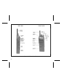
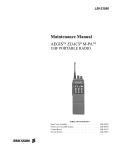
INTRODUCTION
This manual describes the operation of the
M-PA two-way FM Select, Scan, and System model
portable radios.
Operating controls on the radio include a rotatable control knob, rotatable volume control, a 4button keypad (Scan model) or 16-button keypad
(System model), push-to-talk, emergency and monitor buttons. The on/off power switch for the unit is
located on the removable battery pack.
The 8-digit alphanumeric liquid crystal display
(LCD) on the front of the radio displays the operating
status of the radio. This backlit display also has
status flags for indicating the various operating conditions such as transmitter on, scanning, or emergency mode enabled.
The exact operation of your radio will vary depending upon the mode of operation, the radio’s
programming, and the particular radio system. Consult your radio system’s representative for particular
features that are programmed into your radio.
CONTROLS
ON/OFF SWITCH
The ON/OFF SWITCH is located on the battery
pack. Sliding this switch up will supply power to the
radio from the battery pack. An audible click will be
heard and the "ON" indicator will be exposed. When
the radio is turned on, it will perform a power-up self
test and then resume operation on the previous
operating channel as displayed in the LCD. Sliding
the switch down will turn the radio off.
VOLUME CONTROL KNOB
The VOLUME CONTROL KNOB is a rotatable
control on the top of the radio used to adjust the
receiver’s audio level in the speaker. Rotating this
knob in a clockwise direction will increase the audio
level. Counter-clockwise rotation will decrease the
audio level. Minimum levels may be programmed into
the radio to prevent missed calls due to too low of a
volume setting.
CONTROL KNOB
The rotatable 16-position CONTROL KNOB located on the top of the radio is programmed to select
5
the operating channel, mode, or specific Channel
Guard encode/decode tones. See MODE/CHANNEL/CG SELECTION for details. A stop plate may
be installed under the knob to limit the maximum
number of positions to less than sixteen (16). It is
normally factory installed for fifteen (15) positions.
Some radios may be programmed with this knob
disabled.
"CG" and/or "T99" will turn on. The MONITOR BUTTON may then be used to toggle CG and/or T99
between disabled and enabled by pressing and holding it for at least one (1) second; the appropriate
status flag will toggle on or off. The MONITOR BUTTON is also used to reset T99 operation after a call
is received.
EMERGENCY BUTTON
PTT BUTTON
Pressing the PTT BUTTON on the side of the
radio will enable the radio’s transmitter. The "TX"
status flag in the display will turn on when the radio
is transmitting. Releasing the PTT BUTTON will return operation to receive mode.
MONITOR BUTTON
The MONITOR BUTTON is used to unsquelch
the receiver. Momentarily pressing this button will
disable squelch and the receiver noise will be heard
in the speaker.
If programmed enabled for the selected channel,
Channel Guard (CG) and/or Type 99 (T99) signalling
will be enabled when the channel is selected. If CG
and/or T99 are enabled, the appropriate status flag
6
The EMERGENCY BUTTON is the small red
button located on top of the radio near the antenna.
If this button is programmed for emergency operation, pressing it for at least one (1) second will cause
the radio to transmit GE-STAR emergency signalling.
The "EMG" status flag will turn on. GE-STAR is
transmitted according to one of several different programmable methods. See EMERGENCY OPERATION for details.
This button may also be programmed as an home
mode button. If programmed in this manner, pressing
it will switch operation to the programmed home
mode.
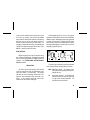
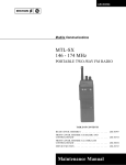
Figure 1 - M-PA Personal Radio
Figure 2 - M-PA Radio (Top View)
7
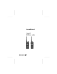
SIDE VIEW
FRONT VIEW
Figure 3 - M-PA Scan Model Radio
8
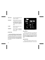
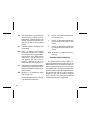
MENU BUTTON (Scan Model)
Pressing the MENU button causes the radio to
scroll through up to six (6) different menus programmed into the radio. After the desired menu is
displayed, the feature within the menu is selected
with the SEL button. The menus that may be programmed are:
Menu Display
Function Or Use
"CHANNEL"
The MENU and SEL buttons are
programmed for channel selection. When this display appears,
select the desired channel with
the SEL button and then press
EXIT.
"MODE"
The MENU and SEL buttons are
programmed for mode selection.
When this display appears, select the desired mode by pressing the SEL button and then
press EXIT.
"PHONE"
Allows selection of one (1) of the
ten (10) programmed telephone
numbers for automatic dialling.
"KEY LOCK"
Allows the keypad buttons to be
locked or unlocked.
"SCAN A/D"
Allows channels to be added to
or deleted from the scan list for
the current mode. The priorityone channel and the priority-two
channel are also set within this
menu.
"ALERT"
Allows the alert tones to be disabled or enabled.
Figure 4 - M-PA Scan Model Keypad
SELECT BUTTON
Selecting different features within each menu is
accomplished with the SEL button. First, the menu
mode must be enabled and the desired menu must
be chosen by pressing and releasing the MENU
button until the desired menu appears in the display.
9
After the menu is chosen, the desired function or
feature is selected by pressing the SEL button. For
example, to disable the alert tones, press MENU until
"ALERT" is displayed then press SEL to select "DISABLED". Next press the EXIT button.
EXIT BUTTON
Pressing the EXIT button will cause the radio to
exit the current menu display and return operation to
the channel currently selected. If the menu mode is
not enabled when the button is pressed, pressing this
button will turn the display and keypad backlighting
on for thirty (30) seconds if the backlight is programmed on.
MENU BUTTON (System Model)
Pressing the MENU button causes the radio to
scroll through up to seven (7) different menus programmed into the radio. After the desired menu is
displayed, the feature within the menu is selected
with the SEL button. The menus that may be programmed are:
Menu Display
Function Or Use
"CHANNEL"
The MENU and SEL buttons are
programmed for channel selection. When this display appears,
select the desired channel with
the SEL button and then press
EXIT.
"MODE"
The MENU and SEL buttons are
programmed for mode selection.
When this display appears, select the desired mode by pressing the SEL button and then
press EXIT.
"PHONE"
Allows selection of one(1) of the
ten (10) programmed or user entered telephone numbers for
automatic dialling.
SCAN BUTTON
Pressing the SCAN button on the keypad will
toggle scan operation on and off. When the radio is
scanning, the "SCN" status flag in the display will
show and all channels on the scan list will be
scanned. See SCANNING CHANNELS for additional details.
10
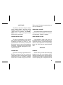
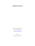
SIDE VIEW
FRONT VIEW
Figure 5 - M-PA System Model Radio
11
"KEY LOCK"
Allows the keypad buttons to be
locked or unlocked.
"SCAN A/D"
Allows channels to be added to
or deleted from the scan list for
the current mode. The priorityone channel and the priority-two
channel are also set within this
menu.
"ALERT"
Allows the alert tones to be disabled or enabled.
"PHN EDIT"
Allows editing of the telephone
phone numbers programmed
into the radio.
EXIT BUTTON
Pressing the EXIT button will cause the radio to
exit the current menu display and return operation to
the channel currently selected. If the menu mode is
not enabled when the button is pressed, pressing this
button will turn the display and keypad backlighting
on for thirty (30) seconds (if the backlight is programmed on).
Figure 6 - M-PA Scan Model Keypad
SCAN BUTTON
Pressing the SCAN button on the keypad will
toggle scan operation on and off. When the radio is
scanning, the "SCN" status flag in the display will
show and all channels on the scan list will be
scanned. See SCANNING CHANNELS for additional
details.
SELECT BUTTON
Selecting different features within each menu is
accomplished with the SEL button. First, the menu
12
mode must be enabled and the desired menu must
be chosen by pressing and releasing the MENU
button until the desired menu appears in the display.
After the menu is chosen, the desired function or
feature is selected by pressing the SEL button. For
example, to disable the alert tones, press MENU until
"ALERT" is displayed then press SEL to select "DISABLED". Next press the EXIT button.
LCD backlighting will turn on for a short period
anytime an active button is pressed or the CONTROL
KNOB is rotated. Backlighting may be programmed
to remain off at all times. Pressing the EXIT button
when the menu mode is not enabled will turn display
and keypad backlighting on for thirty (30) seconds (if
backlight programming is on).
DTMF KEYPAD
Telephone interconnect calls can be made using
the 12-button DTMF keypad. This keypad is enabled
when a channel programmed for DTMF operation is
selected. See TELEPHONE INTERCONNECT
CALLS for details.
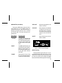
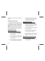
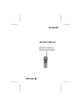
Figure 7 - Liquid Crystal Display
INDICATORS
The status flags located along the top and bottom
of the display indicate operating status as follows:
The radio’s liquid crystal display (LCD) located
on the front panel has eight (8) alphanumeric characters and eleven (11) status flags. This display
indicates the current operating channel and it displays the menu information when this mode is enabled. It also displays telephone interconnect
numbers and various other messages.
EMG EMerGency mode - On indicates emergency GE-STAR signalling has been initiated by the user.
HI
HIgh power transmit - On indicates the
selected channel has been programmed
for high power transmit operation. Off
indicates low power transmit.
13
T99
TX
Type 99 tone decode - On indicates Type
99 tone decoding is enabled on the selected channel. Flashing indicates a T99
selective call has been received and the
radio must be reset to receive another
T99 call.
Transmitter enabled - On when the radio
is transmitting.
BSY BuSY - On indicates a carrier is being
received (the channel is busy). Note that
if the selected channel is programmed for
Channel Guard (CG), Digital Channel
Guard (DCG), or Type 99 (T99) tone decode operation, the radio will not unsquelch if a valid tone or code is not
received; the BSY status flag will be on.
CG
Channel Guard - On indicates tone Channel Guard (CG) or Digital Channel Guard
(DCG) encode/decode is enabled on the
selected channel.
BAT BATtery low - On indicates the battery
pack’s charge is low.
The following status flags are for use with
Scan and System model radios:
14
S
Scan list - On indicates the selected channel is on the scan list.
1
priority 1 - On indicates the selected channel is designated as the priority-one scan
channel.
2
priority 2 - On indicates the selected channel is designated as the priority-two scan
channel.
SCN SCaN mode - On indicates the radio is
scanning.
UNIVERSAL DEVICE CONNECTOR
The Universal Device Connector (UDC) is located on the side of the radio just above the PTT and
MONITOR BUTTONS. This connector provides connections for the external accessories such as a headset, a speaker-mike, or an emergency lanyard. When
the radio is locked in a vehicular charger/repeater the
UDC provides the audio and control connections
between the radio and the vehicular charger/repeater. The UDC is also used by the maintenance
personnel when the radio is programmed.
ALERT TONES
The M-PA uses alert tones or "beeps" to indicate
various operating conditions. Alert tones may be
enabled or disabled via the menu mode if the
"ALERT" feature is programmed. See "ALERT"
MENU for details. The alert tones may be disabled
when the radio is programmed.
TON is pressed. This feature is programmable on or
off on a per channel basis.
RECEIVE ONLY CHANNEL
If the selected channel is programmed as receive
only, the radio will sound an alert tone if a transmission is attempted. "RX ONLY" is displayed.
CARRIER CONTROL TIMER
RADIO/CHANNEL FAILURE
This feature, programmable on a per channel
basis, prevents unnecessary channel traffic and radio damage in the event of a "stuck" mic. If the
programmed timer times-out during a transmission
the radio will sound an alert tone and disable the
transmission. The beeping tone will continue until the
PTT BUTTON is released. Releasing the PTT BUTTON resets the timer.
If the synthesizer is unable to lock correctly on
the selected channel, or another radio failure occurs,
an alert tone will sound. If incorrect programming is
detected or the synthesizer fails to lock, the display
flashes "NO LOCK" then the selected channel’s
name.
CHANNEL BUSY
POWER-UP
If the radio is receiving a signal when the PTT
BUTTON is pressed, an alert tone will warn the
operator that the radio is receiving a carrier and the
transmission will not occur. "RX BUSY" is displayed
and the alarm is sounded as long as the PTT BUT-
After the battery pack and antenna have been
installed, turn the radio on by sliding the ON/OFF
SWITCH on the battery pack up. After the radio has
completed a power-up self-test, it will begin operation
on the last operating state as displayed in the LCD.
OPERATION
15
If programmed on, the power-up alert tone (beep) will
be heard.
MODE/CHANNEL/CG SELECTION
The M-PA Scan and System model radios may
be programmed with up to 192 different radio channels. A maximum of 12 modes of 16 channels each
or 16 modes of 12 channels each may be programmed into the radio (12 x 16 = 192). Select the
desired mode (bank of channels) and channel, or
channel and Channel Guard (CG), according to the
radio’s programming as follows:
MENU And SEL Selects Mode
CONTROL KNOB Selects Channel (And CG)
16
1.
Press the MENU button until "MODE" appears in the display.
2.
Press the SEL button to select the desired
mode. The selected mode’s name will appear in the display.
3.
Press the EXIT button to switch radio operation to the selected mode and exit the menu.
4.
Select the desired channel by rotating the
CONTROL KNOB until the desired channel’s name appears in the display.
CONTROL KNOB Selects Mode
MENU And SEL Selects Channel (And CG)
1.
Select the correct mode by rotating the
CONTROL KNOB until the desired mode’s
name appears in the display.
2.
Press the MENU button until "CHANNEL"
appears in the display.
3.
Press the SEL button until the desired channel’s name appears in the display.
4.
Press the EXIT button to switch radio operation to the displayed channel and exit the
menu.
MENU and SEL Selects Modes And Channels
CONTROL KNOB Selects Channel Guard
1.
Press the MENU button until "MODE" appears in the display.
2.
Press the SEL button until the desired
mode’s name appears in the display.
3.
Press the MENU button until "CHANNEL"
appears in the display.
4.
Press the SEL button until the desired channel’s name appears in the display.
5.
Press the EXIT button to switch radio operation to the new mode and channel, and exit
the menu.
6.
Select the desired Channel Guard using the
CONTROL KNOB. The "CG" status flag will
turn on if the selected position has CG
programmed. Position fifteen (15) is a nonCG position; it may not be programmed with
a Channel Guard. Position sixteen (16) is a
default channel CG position; selecting it will
switch CG to the CG programmed for the
selected channel.
and complete the power-up self-test and
beep if the power-up alert tone is programmed on.
2.
Select the desired operating mode, channel, and/or Channel Guard. See the
MODE/CHANNEL/CG SELECTION for details.
3.
Press the MONITOR BUTTON to disable
squelch and adjust the VOLUME CONTROL KNOB for the approximate desired
speaker audio level. Pressing the MONITOR BUTTON may affect Channel Guard
and/or Type 99 tone operation if programmed for the selected channel.
4.
When a transmission is received, the receiver will unsquelch and it will be heard in
the speaker. However, if the selected channel is programmed for Channel Guard or
Type 99 tone operation, the receiver will not
unsquelch unless the correct CG or T99
tone is received.
5.
Adjust the volume as necessary.
RECEIVING A MESSAGE
1.
Slide the ON/OFF SWITCH on the battery
pack to the on position. The radio will initiate
17
TRANSMITTING A MESSAGE
1.
Select the desired mode, channel, and/or
Channel Guard. See the MODE/CHANNEL/CG SELECTION for details..
2.
Ensure no one is transmitting on the selected channel by pressing the MONITOR
BUTTON to disable squelch or observing
the display for the absence of the "BSY"
status flag. If the Channel Busy Lockout
feature is programmed for the selected
channel, the radio will not transmit when the
channel is busy.
3.
Press and hold the PTT BUTTON. The "TX"
and "BSY" status flags are displayed.
4.
Hold the radio approximately three inches
from your mouth and speak into the microphone in a normal voice.
5.
Release the PTT BUTTON when the transmission is complete. If the transmission
exceeds the programmed Carrier Control
Timer limit, the radio will unkey and an alert
tone will sound.
6.
18
Listen for a reply.
EMERGENCY OPERATION
The radio may be programmed to transmit GESTAR emergency signalling when the EMERGENCY
BUTTON is pressed or from a UDC connected lanyard. If the EMERGENCY BUTTON is programmed
for GE-STAR emergency activation, press it for approximately one (1) second to activate the transmission. If the lanyard is programmed for activation,
follow the instructions provided with it. GE-STAR is
programmed to transmit in one of the following methods:
•
GE-STAR is transmitted on a predetermined
mode and channel regardless of the selected
channel. In this case the selected channel is
available for voice and the radio will periodically "jump" to the predetermined channel
and send the emergency message and then
"jump back" to the selected channel for voice
operation.
•
GE-STAR is transmitted on the selected
channel. If the channel is changed the emergency bursts will follow the newly selected
channel.
•
The radio switches to and stays on a predetermined mode and channel and GE-STAR
is transmitted on that channel. Rotating the
CONTROL KNOB will not change channels.
Turning the radio off and back on will reset
this condition.
•
GE-STAR is sent on the selected channel
and the radio locks onto that channel. Rotating the CONTROL KNOB will not change
channels. Turning the radio off and then
back on will reset this condition.
SCANNING CHANNELS (Scan and System models)
The M-PA may be programmed for non-priority
scan, dual-priority scan, or scan operation may be
disabled. Scan programming options include a keypad entered scan list or a fixed scan list. Priority scan
programming options include a fixed priority-one
channel or the selected channel as the priority-one
channel.
The radio may be programmed to scan only the
channels in the current mode or it may be programmed to scan across modes.
Scan rate will vary depending upon the number
of channels on the scan list and whether or not the
radio is programmed to scan for Channel Guard.
Fewer channels will result in a faster scan rate. All
scan functions are retained in memory when the
battery pack is removed.
The radio will not scan when the emergency
mode is enabled ("EMG" status flag is on).
Adding Channels To And Deleting Channels
From The Scan List
If the "SCAN A/D" menu is programmed, channels may be added to and deleted from the scan list
of each mode as follows:
1.
Select the desired mode and channel. If the
selected channel is currently on the list, the
"S" status flag will be on.
2.
Press the MENU button until "SCAN A/D"
is displayed.
3.
Press the SEL button until the desired priority indicator appears: "S" for non-priority,
"2" for priority-two, "1" for a priority-one, or
no indicator to remove the channel from the
scan list. If a new priority channel is selected the previous corresponding priority
channel will become a non-priority scan
19
channel. One of the following messages
may be momentarily displayed:
TELEPHONE INTERCONNECT CALLS
SCAN Model
"SCAN DIS" - – The radio is not programmed
to scan.
"FIXED P1" -
– A priority-one channel has
been programmed into the
radio. A new priority-one
channel can not be selected.
"FIXD LST" -
– A fixed scan list is pro-
grammed into the radio. It is
not possible to change the list
without reprogramming the
radio.
4.
To add or delete additional channels, repeat
steps 2 through 4.
5.
Press the EXIT button to return to normal
operation.
Using Scan
Toggle scan on or off by pressing SCAN. The
"SCN" status flag turns on when the radio is scanning.
20
Telephone interconnect calls can be placed on
radio channels equipped with this capability. Each
channel programmed into the radio can be programmed for telephone interconnect by enabling it for
DTMF dial operation. One (1) of the ten (10) programmed telephone numbers can be selected and
automatically dialled.
Communication takes place in a simplex mode.
In other words, the PTT BUTTON must be pressed
each time you wish to transmit and it must be released to receive.
Placing A Call
Ten (10) telephone numbers can be programmed
in the radio for automatic dial operation. Typically,
telephone numbers programmed into the radio by the
maintenance personnel each have a specific name
(8 characters maximum) assign. For example: "OFFICE" or "HOME". To recall a number and complete
a call, proceed as follows:
1.
If the "SCN" status flag is on, press SCAN
to turn scan off.
2.
Select a channel in your radio system that
has telephone interconnect capability. The
radio should be programmed for DTMF operation on this channel.
3.
Press the MENU button until "PHONE" appears in the display.
4.
Press the SEL button to scroll through the
phone list until the programmed name for
the desired telephone number appears in
the display.
5.
Press and release the PTT BUTTON to
automatically dial the selected number.
6.
When the called party answers, press the
PTT BUTTON to transmit and release it to
receive. Repeat as needed.
7.
At the completion of the call, press the EXIT
button. The radio will then transmit the disconnect digit to hang-up.
If programmed for dual-priority scan operation,
the priority-one, priority-two and the remaining channels will be scanned. Once a carrier is detected and
if programmed, the correct Channel Guard is decoded, the display will indicate the channel. Scanning of the priority-one and priority-two channels will
continue. Should a priority-one or two channel carrier, regardless of Channel Guard, be detected while
a non-priority channel is being received, the display
name is updated, the applicable status indicator, "1"
or "2" lights, and the channel is switched to the priority
channel. Scanning of the priority-one channel will
continue if a message is being received on the priority-two channel.
If programmed for non-priority scan operation,
once a carrier is detected, and if programmed, the
correct Channel Guard is decoded, the display will
indicate the detected channel. Scanning will stop
and the radio will remain on the channel until the
carrier ceases. Scanning will then resume with the
selected channel’s name displayed.
21
TELEPHONE INTERCONNECT CALLS
SYSTEM MODELS
Telephone interconnect calls can be placed on
radio channels equipped with this capability. Each
channel programmed into the radio can be programmed for telephone interconnect by enabling it for
DTMF dial operation. One (1) of the ten (10) programmed telephone numbers can be selected and
automatically dialled.
Communication takes place in a simplex mode.
In other words, the PTT BUTTON must be pressed
each time you wish to transmit and it must be released to receive.
The keypad on the radio’s front panel allows the
operator to make telephone interconnect calls on
radio systems equipped with this capability. Telephone numbers may be manually dialed using the
DTMF numeric keypad, or one (1) of the ten (10)
programmed or stored numbers can be selected and
automatically dialed. Each channel may be programmed for telephone interconnect by enabling it for
DTMF dial operation.
22
Most systems require an " " to be sent at the
beginning of a transmission to get a dial tone. Others
require "#". After the dial tone is received, the number is sent.
*
Communication takes place in a simplex mode.
In other words, the PTT BUTTON must be pressed
each time you wish to transmit and it must be released to receive.
At the completion of the call most systems require a "#" to be sent to disconnect the user from the
telephone system. Others require " ".
*
Placing A Manually Dialed Call
1.
If the "SCN" status flag is on, press SCAN
to turn scan off.
2.
Select a channel in your radio system that
has telephone interconnect capability. The
radio should be programmed for DTMF operation on this channel.
3.
Press and hold the PTT BUTTON to key the
transmitter.
4.
While holding the PTT BUTTON, press
either the " " button or the "#" button as
required by the radio system to obtain a
telephone line. The radio will transmit the
selected tone.
*
5.
Release the PTT BUTTON and listen for a
dial tone.
6.
When the dial tone is received, press an
hold the PTT BUTTON and dial the desired
telephone number. As you dial each number, the DTMF sidetone will be heard in the
speaker as the radio transmits the DTMF
tone.
7.
Release the PTT BUTTON when the dial
sequence is complete.
8.
When the called party answers, press the
PTT BUTTON each time you wish to talk
(transmit) and release it when you wish to
listen (receive). If desired, enable private
mode by pressing the PVT button.
9.
At the completion of the call, press and hold
the PTT BUTTON and then press the "#" or
" " button as the telephone interconnect
system requires. Release the PTT BUTTON.
*
Placing An Automatically Dialed Call
Ten (10) telephone numbers can be programmed
or stored in the radio for automatic dial operation.
Typically, telephone numbers that are programmed
into the radio by the maintenance personal each have
a specific name (8 characters maximum) assigned.
For example: "OFFICE" or "HOME". Telephone
numbers that are stored in the radio using the numeric keypad are named "PHONE x" (where "x" is
the storage location 1 - 10) when they are stored.
When stored numbers are later recalled using the
"PHONE" menu, the last eight (8) entered digits of
the number will be the name that appears in the
display. To recall a programmed or stored number
and complete a call, proceed as follows:
1.
If the "SCN" status flag is on, press SCAN
to turn scan off.
2.
Select a channel in your radio system that
has telephone interconnect capability. The
radio should be programmed for DTMF operation on this channel.
3.
Press the MENU button until "PHONE" appears in the display.
23
4.
Press the SEL button to scroll through the
phone list until the programmed or stored
name for the desired telephone number appears in the display.
5.
Press and release the PTT BUTTON to
automatically dial the selected number.
6.
When the called party answers, press the
PTT BUTTON to transmit and release it to
receive. Repeat as needed.
7.
At the completion of the call, press the EXIT
button. The radio will then transmit the disconnect digit to hang-up.
Editing The Programmed Telephone Numbers
Or Storing A New Telephone Number
Any of the programmed or stored telephone numbers may be edited using the "PHN EDIT" menu. This
menu also allows new phone numbers to be stored
(added) to the list. Up to a maximum to ten (10)
different numbers can be programmed and/or stored
in the radio.
1.
24
Press the MENU button until "PHN EDIT"
appears in the display.
2.
Press the SEL button until the name for the
desired telephone number appears in the
display.
3.
Enter the new number using the numeric
keypad. If a mistake is made, press the
MONITOR BUTTON to abort and then enter
the correct number.
4.
After the correct number has been entered,
press EXIT to enter the new number and
return to normal operation.
"KEY LOCK" MENU (Scan and System models)
The "KEY LOCK" menu allows the keypad
(SCAN button and the twelve (12) numeric buttons)
to be locked or disabled to prevent accidental activation. If this menu is programmed into the radio, lock
and unlock the keypad as follows:
Lock The Keypad
1.
If the "SCN" status flag is on, press SCAN
to turn scan off.
2.
Press the MENU button until "KEY LOCK"
appears in the display.
3.
Press the SEL button until "LOCKED" is
displayed.
2.
Press the MENU button until "ALERT" appears in the display.
4.
To lock the keypad press the EXIT button.
3.
Press the SEL button until "DISABLED" is
displayed.
4.
To disable the tones press the EXIT button.
Unlock The Keypad
1.
Press the MENU button until "KEY LOCK"
appears in the display.
Enable The Alert Tones
2.
Press the SEL button until "UNLOCKED" is
displayed.
1.
Press the MENU button until "ALERT" appears in the display.
3.
To unlock the keypad press the EXIT button.
2.
Press the SEL button until "ENABLED" is
displayed.
3.
To enable the tones press the EXIT button.
"ALERT" MENU (Scan and System models)
The "ALERT" menu allows the alert tones to be
disabled or enabled. If this menu is programmed into
the radio, disable and enable the alert tones as
follows:
Disable The Alert Tones
1.
If the "SCN" status flag is on, press SCAN
to turn scan off.
PROGRAMMABLE FEATURES
The radio’s features or "personality" are programmed using an IBM PC or compatible computer.
For field programming, a full screen portable PC can
be used. Programming software is provided on 5-1/4
floppy or 3-1/2 inch disks. This software uses a series
of screens and windows to guide you through a
programming session.
25
PROGRAMMABLE BY CHANNEL
26
RADIO PROGRAMMABLE
•
Transmit and Receive Frequencies
•
Minimum Volume Level
•
8-Character Alphanumeric Display (Channel
Designator)
•
GE-STAR Lanyard
•
•
Emergency Channel
Tone or Digital Channel Guard Encode/Decode
•
Vehicular Charger Backlight
•
Type 99 Tone Decode
•
•
Control Knob Selects Channels, Modes or
Channel Guard
Transmit Power Level High or Low
•
•
Mode Control (Scan or System Radio)
Transmit STE On or Off
•
•
Menu Selections (Scan or System Radio)
Channel Busy Lockout
•
•
Carrier Control Timer
•
Backlight On or Off
Home Mode or Home Channel (Depending
on Control Knob Programming (Scan or System Radio)
•
Alert Tones On of Off
•
•
Scan Enabled or Disabled (Scan or System
Radio)
Switch Crystal Frequency
•
•
GE-STAR
Priority-One and Priority-Two Scan Channel
(Scan or System Radio)
•
GE-STAR sent with Channel Guard
•
•
Channel Scan (Scan or System Radio)
Selected Channel is Priority-One Scan
Channel (Scan or System Radio)
•
DTMF Enabled Per Mode (Scan or System
Radio)
•
Ten (10) Telephone Numbers (Scan or System Radio)
OPERATING TIPS
OPERATING RULES AND REGULATIONS
Antenna location and condition is important
when operating a portable radio. Operating the radio
in low areas of terrain, under power lines or bridges,
inside of a vehicle or in a metal or steel framed
building can severely reduce the range of the unit.
Mountains and buildings can also reduce the range
of the unit.
Two-way FM radio systems must be operated in
accordance with the rules and regulations of the
Federal Communications Commission (FCC). As an
operator of two-way radio equipment, you must be
thoroughly familiar with the rules that apply to your
particular type of radio operation. Following these
rules will help eliminate confusion, assure the most
efficient use of the existing radio channels, and result
in a smoothly functioning radio network.
In areas where transmission or reception is poor,
some improvement may be obtained by insuring that
the antenna is vertical. Moving a few yards in another
direction or moving to a higher elevation may also
improve communication. Vehicular operation can be
aided with the use of an externally mounted antenna.
Battery condition is another important factor in
the trouble free operation of a portable radio. Always
properly charge the batteries.
Always observe all of the Federal Communication Commission’s rules and regulations.
When using your two-way radio, remember these
rules:
1.
It is a violation of FCC rules to interrupt any
distress or emergency message. As your
radio operates in much the same way as a
telephone "party line", always listen to make
sure that the channel is clear and/or observe the display for the absence of the
"BSY" status flag before transmitting.
Emergency calls have priority over all other
messages. If someone is sending an emergency message - such as reporting a fire or
asking for help in an accident - KEEP OFF
THE AIR!
27
2.
The use of profane or obscene language is
prohibited by Federal law.
3.
It is against the law to send false call letters,
or false distress or emergency messages.
4.
call letters. Refer to the rules that apply to
your particular type of operation for the
proper procedure.
8.
The FCC requires that you keep conversations brief and confine them to business. To
save time, use coded messages whenever
possible.
No changes or adjustments shall be made
to the equipment except by an authorized or
certified electronic technician.
BATTERY PACKS
INSTALLING THE BATTERY PACK
5.
6.
7.
28
Using your radio to send personal messages (except in an emergency) is a violation of FCC rules. You may send only those
messages that are essential for the operation of your business.
It is against Federal law to repeat or otherwise make known anything you overhear on
your radio. Conversations between others
sharing your channel must be regarded as
confidential.
The FCC requires that you identify yourself
at certain specific times by means of your
1.
Ensure the ON/OFF SWITCH on battery
pack is in the off position.
2.
Hold the radio and battery pack with the
back of them facing you.
3.
Align the battery pack and radio slide
grooves. See Figure 8.
4.
Slide the battery pack fully into the radio
until the battery release latch clicks into
place.
Figure 8 - Installing the Battery Pack
REMOVING THE BATTERY PACK
1.
Ensure the ON/OFF SWITCH on the battery
pack is in the off position.
2.
Press down on the battery release latch and
slide the battery pack out in the direction of
the release latch. See Figure 9.
Figure 9 - Removing the Battery Pack
CHARGING THE BATTERY PACKS
After receiving a new rechargeable battery pack
from the factory, it should be fully charged before
placing it into service. This also applies to rechargeable batteries that have been stored for long periods.
When the battery pack requires charging the radio
will signal the operator with an alert tone and the
"BAT" status flag will turn on.
29
Chargers are available with nominal charge
times of 1 hour (rapid) and 14 hours (standard).
Combinations include single (1) and multi (5) position, standard and rapid charge units. In addition, the
vehicular chargers/repeaters simultaneously charge
the battery packs while the radio is operating. For
specific instructions refer to the applicable charger
Operating Manual.
The rechargeable batteries used with the radio
can develop a reduced capacity condition sometimes
called the "Memory Effect". This condition can occur
when a battery is continuously charged for long
periods or when a regularly performed duty cycle
allows the battery to expend only a limited portion of
its capacity. The battery pack may show a severe
decrease in its ability to deliver full capacity for an
extended period. Any rechargeable battery pack
showing signs of reduced capacity should be returned to a qualified service center for inspection.
RECHARGEABLE BATTERY PACK DISPOSAL
The product that you have purchased
contains a rechargeable, recyclable
battery. At the end of its useful life,
under various state and local laws, it
may be illegal to dispose of this battery into the municipal waste stream. Check with your
local solid waste officials for details in your area for
recycling options or proper disposal. Call Toll Free
1-800-8-BATTERY for information and/or procedures for returning rechargeable batteries in your
state.
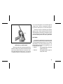
SWIVEL MOUNT REMOVAL AND
REPLACEMENT
To remove the swivel mount, slide a flat blade
screwdriver underneath the spring retainer and twist.
While twisting, slide the swivel mount out from under
the holder. See Figure 10.
To replace the swivel mount, place the end of the
swivel in the grooves in the radio and slide the mount
up until it snaps in place.
30
D, E, F and G atmospheres. Non-Incendive approval
includes Class I, Division 2 hazardous locations in
the presence of Groups A, B, C, and D atmospheres.
Hazardous locations are defined in the National
Electrical Code. Useful standards NFPA 437A and
NFPA 437M for the classifications of hazardous areas
may be ordered from the National Fire Protection
Association, Batterymarch Park, Quincy, MA 02269.
BATTERIES
Figure 10 - Swivel Mount Removal and Replacement
INTRINSICALLY SAFE USAGE
Selected portable radios with appropriate factory
installed F4 Options are certified as Intrinsically Safe
by the Factory Mutual Research Corporation. Intrinsically Safe approval includes Class I, II, III, Division
1 hazardous locations in the presence of Groups C,
Only batteries identified with a green latch shall
be used with a portable radio that is rated and labeled
as Factory Mutual Intrinsically Safe. Use of nonspecified batteries voids Factory Mutual approval. The
following battery pack options are approved for use
in intrinsically safe radios:
• PAPA1F
Rechargeable Battery, Extra High
Capacity (Tall Case)
• PAPA1G
Rechargeable Battery, High Capacity (Short Case)
31
ACCESSORIES
• PANC1N
Antenna, 440 - 512 MHz,
Whip
The following accessories are approved for use
with intrinsically safe radios. Use of accessories
other than those listed voids Factory Mutual approval.
• PAAC1J
Earpiece Kit
• PANC1U
Antenna, 378-440 MHz, Helical
• PANC1V
Antenna, 492-512 MHz, Helical
• PAHC1C
Belt Clip
• PAAE3E
Speaker/Microphone
• PAHC1D
Swivel Mount with Belt Loop
• PAAE3G
Speaker/Microphone/
Antenna
• PAHC5N
Case, Leather, with Belt Loop
(Short Case)
• PANC1B
Antenna, 136 - 151 MHz, Helical
• PAHC1F
• PANC1C
Antenna, 146 - 162 MHz, Helical
Case, Leather, with Belt Loop (Tall
Case)
• PANC1D
Antenna, 157 - 174 MHz, Helical
• PAHC1K
• PANC1F
Shoulder Strap, Leather, with
Mounting Plate
Antenna, 440 - 470 MHz, Helical
• PANC1G
• PAHC5R
Holster, Plastic
Antenna, 470 - 494 MHz, Helical
• PANC1L
Antenna, 403 - 440 MHz, Whip
32
WARRANTY
A.
Ericsson Inc. (hereinafter "Seller") warrants to the original purchaser for use (hereinafter "Buyer") that Equipment manufactured by Seller shall be free
from defects in material, workmanship and title, and shall conform to its published specifications. With respect to any Equipment not manufactured by
Seller (except for integral parts of Seller’s Equipment to which the warranties set forth above shall apply). Seller gives no warranty, and only the warranty,
if any, given by the manufacturer shall apply. Batteries are excluded from this warranty but are warranted under a separate Nickel-Cadmium Battery
Warranty.
B.
Seller’s obligations set forth in Paragraph C below shall apply only to failures to meet the above warranties (except as to title) occurring within the following
periods of time from date of sale to the Buyer and are conditioned on Buyer’s giving written notice to Seller within thirty (30) days of such occurrence:
1. for fuses, incandescent lamps, vacuum tubes and non-rechargeable batteries, operable on arrival only.
2. for parts and accessories (except as noted in B.1) sold by Seller’s Service Parts Operation, ninety (90) days.
3. for all other Equipment of Seller’s manufacture, one (1) year.
C.
If any Equipment fails to meet the foregoing warranties, Seller shall correct the failure at its option (i) by repairing any defective or damaged part or parts
thereof, or (ii) by making available at Seller’s factory any necessary repaired or replacement parts. Any repaired or replacement part furnished hereunder
shall be warranted for the remainder of the warranty period of the Equipment in which it is installed. Where such failure cannot be corrected by Seller’s
reasonable efforts, the parties will negotiate an equitable adjustment in price. Labor to perform warranty service will be provided at no change only for
the Equipment covered under Paragraph B.3, and only during the first three (3) months following the date of sale to the Buyer. Thereafter, labor will be
charged at prevailing rates. To be eligible for no-charge labor, service must be performed by an Authorized Service Center or other Servicer approved
for these purposes either at its place of business during normal business hours, for mobile or personal equipment, or at the Buyer’s location, for fixed
location equipment. Service on fixed location equipment more than thirty (30) miles from the Service Center or other approved Servicer’s place of business
will include a charge for transportation. Equipment located off-shore is not eligible for no-charge labor.
D.
Seller’s obligations under Paragraph C shall not apply to any Equipment, or part thereof, which (i) has been modified or otherwise altered other than
pursuant to Seller’s written instructions or written approval or, (ii) is normally consumed in operation or, (iii) has a normal life inherently shorter than the
warranty periods specified in Paragraph B, or (iv) is not properly stored, installed, used, maintained or repaired, or, (v) has been subjected to any other
kind of misuse or detrimental exposure, or has been involved in an accident.
E.
The preceding paragraphs set forth the exclusive remedies for claims (except as to title) based upon defects in or nonconformity of the Equipment, whether
the claim is in contract, warranty, tort (including negligence), strict liability or otherwise, and however instituted. Upon the expiration of the warranty period,
all such liability shall terminate. The foregoing warranties are exclusive and in lieu of all other warranties, whether oral, written, expressed, implied or
statutory. NO IMPLIED OR STATUTORY WARRANTIES OF MERCHANTABILITY OR FITNESS FOR PARTICULAR PURPOSE SHALL APPLY. IN NO
EVENT SHALL THE SELLER BE LIABLE FOR ANY INCIDENTAL, CONSEQUENTIAL, SPECIAL, INDIRECT OR EXEMPLARY DAMAGES.
This warranty applies only within the United States.
1-800-592-7711 (Outside USA, 804-592-7711).
ECX-362S
33
NICKEL-CADMIUM BATTERY WARRANTY
A.
B.
C.
D.
E.
Ericsson Inc. (hereinafter "Seller") warrants to the original purchaser for use (hereinafter "Buyer") that nickel-cadmium
batteries supplied by Seller shall be free from defects in material and workmanship, and shall conform to its published
specifications for a period of twelve (12) months from the date of purchase.
For purposes of this warranty, batteries shall be deemed defective if (1) the battery capacity is less than 80% of rated
capacity, or (2) the battery develops leakage.
If any battery fails to meet the foregoing warranty, Seller shall correct the failure by issuing a replacement battery upon
receipt of the defective battery at an Authorized Service Center (ASC). To obtain the name and address of an ASC,
ask your salesperson, consult the Yellow Pages, or call the number printed at the bottom of this page.
Replacement batteries shall be warranted only for the remaining unexpired warranty period of the original battery. This
warranty becomes void if:
(1) The battery has been subjected to any kind of misuse, detrimental exposure, or has been involved in an accident.
(2) The battery is used in equipment or service other than the radio equipment for which it is specified.
The preceding paragraphs set forth the exclusive remedies for claims (except as to title) based upon defects in or
non-conformity of any battery, whether the claim is in contract, warranty, tort (including negligence), strict liability or
otherwise, and however instituted. Upon the expiration of the warranty period, all such liability shall terminate. The
foregoing warranties are exclusive and in lieu of all other warranties, whether oral, written, expressed, implied or
statutory. NO IMPLIED OR STATUTORY WARRANTIES OF MERCHANTABILITY OR FITNESS FOR PARTICULAR
PURPOSE SHALL APPLY. IN NO EVENT SHALL THE COMPANY BE LIABLE FOR ANY INCIDENTAL, CONSEQUENTIAL, SPECIAL, INDIRECT OR EXEMPLARY DAMAGES.
This warranty applies only within the United States.
1-800-592-7711 (Outside USA, 804-592-7711).
ECX-841C
34
NOTES
35
EMERGENCY NUMBERS
Police
State Police
Fire
Poison Control
Ambulance
Life Saving and
Rescue Squad
Ericsson Inc.
Private Radio Systems
Mountain View Road
Lynchburg, Virginia 24502
1-800-592-7711
(Outside USA, 804-592-7711)
Printed in U.S.A.