1
User’s Manual
F
EPSON®
Y46399102000
FCC COMPLIANCE STATEMENT FOR AMERICAN USERS
This equipment generates and uses radio frequency energy and if not installed and used
properly, that is, in strict accordance with the manufacturer’s instructions, may cause
interference to radio and television reception. It has been type tested and found to comply
with the limits for a Class B computing device in accordance with the specifications in
Subpart J of Part 15 of FCC rules, which are designed to provide reasonable protection
against such interference in a residential installation. However, there is no guarantee that
interference will not occur in a particular installation. If this equipment does cause
interference to radio and television reception, which can be determined by turning the
equipment off and on, the user is encouraged to try to correct the interference by one or
more of the following measures:
.
.
.
.
Reorient the receiving antenna
Relocate the printer with respect to the receiver
Move the printer away from the receiver
Plug the printer into a different outlet so that the printer and receiver are on different
branch circuits.
If necessary, the user should consult the dealer or an experienced radio/television technician
for additional suggestions. The user may find the following booklet prepared by the Federal
Communications Commission helpful:
“Television Interference Handbook”
This booklet is available from the U.S. Government Printing Office, Washington DC 20402.
Stock No. 004-000-00450-7.
WARNING
The connection of a non-shielded equipment interface cable to this equipment will
invalidate the FCC Certification of this device and may cause interference levels that exceed
the limits established by the FCC for this equipment. If this equipment has more than one
interface connector, do not leave cables connected to unused interfaces.
All rights reserved. No part of this publication may be reproduced, stored in a retrieval
system, or transmitted, in any form or by any means, mechanical, photocopying, recording,
or otherwise, without the prior written permission of Epson America, Inc. No patent liability
is assumed with respect to the use of the information contained herein. While every
precaution has been taken in the preparation of this book, Epson America, Inc. assumes no
responsibility for errors or omissions. Neither is any liability assumed for damages resulting
from the use of the information contained herein.
Epson America, Inc. shall not be liable against any damages or problems arising from the use
of any options other than those designated as Original Epson Products by Seiko Epson
Corporation.
Graphics created with UniPaint by Unison World Inc. and EPSON SD-Graph.
Epson and Epson ESC/P are registered trademarks of Seiko Epson Corporation.
IBM is a regostered trademark of International Business Machines Corporation,
SmartPark is a trademark of Epson America, Inc.
Copyright 0 1989 by Epson America, Inc.
Torrance, California
ii
Contents
About This Manual
1
1-1
Unpacking the Printer ............................................................. 1-2
Choosing a Place for the Printer.. .......................................... 1-4
Assembling the Printer.. .......................................................... 1-7
Testing the Printer.. ................................................................ .1-15
Connecting the Printer to Your Computer ........................... 1 - 2 6
Setting Up Your Application Software ................................. 1-29
Chapter 1 Setting up the Printer
2-l
Using Single Sheets ................................................................ .2-2
Using Continuous Paper ........................................................ .2-7
Switching Between Continuous and Single Sheets ............ .2-15
Printing on Special Paper.. ..................................................... .2-22
Chapter 2 Paper Handling
Chapter 3 Using the Printer
3-1
Operating the Control Panel ................................................ ..3- 2
Setting the DIP Switches ........................................................ 3-6
Page length .............................................................................. .3-9
Skip Over Perforation ............................................................ .3-10
Adjusting the Loading Position ............................................ .3-12
Using Short Tear-Off.. ........................................................... .3-15
Selecting Typestyles ............................................................... .3-19
Selecting an International Character Set.. ............................ .3-23
Choosing a Character Table .................................................. .3-25
Data Dump Mode.. ................................................................. .3-27
.*.
C o n t e n t s 111
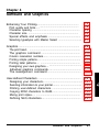
Chapter 4 Software and Graphics
4-1
Enhancing Your Printing.. .....................................................
Graphics ....................................................................................
User-defined Characters.. ........................................................
4-2
4-9
4-21
Chapter 5 Using the Printer Options
5-1
Cut Sheet Feeder ......................................................................
Pull Tractor ...............................................................................
Roll Paper Holder ...................................................................
Interface Boards ......................................................................
5-2
5-18
.5-30
.5-37
Chapter 6 Maintenance
6-1
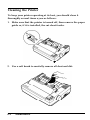
Cleaning the Printer ................................................................
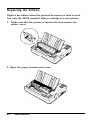
Replacing the Ribbon ..............................................................
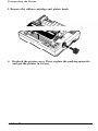
Transporting the Printer .........................................................
6-2
6-4
6-9
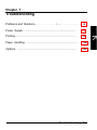
Chapter 7 Troubleshooting
7-1
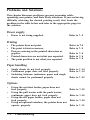
Problems and Solutions ........................................................... 7-2
7-3
Power Supply ...........................................................................
.....................................................................................
.7-4
Printing
Paper Handling ........................................................................ 7-14
7-22
Options .....................................................................................
Chapter 8 Technical Specifications
8-1
Printer Specifications ...............................................................
Interface Specifications ............................................................
Option Specifications ..............................................................
Initialization ..............................................................................
8-2
8-9
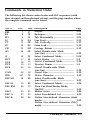
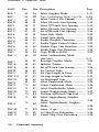
Chapter 9 Command Summary
9-1
8-13
8-15
Using the Command Summary .............................................. 9-2
Commands in Numerical Order ............................................. 9-5
Commands Arranged by Topic .............................................. 9-8
iv
Contents
A-1
Character Tables . . . . . . . . . . . . . . . . . . . . . . . . . . . . . . . . . . . . . . . . . . . . . . . . . . . . . . . . . . . . . . . . . . . . . . . A-2
Appendix
Glossary
GL-1
Index
IN-1
Contents v
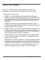
About This Manual
This user’s manual provides fully illustrated, step-by-step
instructions for setting up and operating your Epson’s’ printer.
Finding your way around
Chapter 1 contains information on unpacking, setting up,
testing, and connecting the printer. Be sure to read and follow
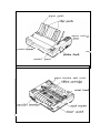
these instructions first. Inside the back cover of this manual are
illustrations of the printer in which all of the major parts are
identified.
Chapters 2 and 3 cover paper handling and general printer
operation. This important information is necessary for the dayto-day operation of your printer.
Chapter 4 shows you how to get the most from your printer. It
includes advice about using software commands, graphics, and
creating your own user-defined characters. Also see Chapter 9
for a useful summary of printer commands.
If the printer does not operate properly or the printed results
are not what you expect, see Chapter 7 for troubleshooting
problems and solutions.
Other chapters contain information on printer options, general
maintenance, and specifications. You will also find a glossary
of printer terms, an appendix of character tables, and an index.
At the back of this manual is a handy Quick Reference card
with the information you are likely to need most often.
About This Manual
1
About This Manual
Conventions used in this guide
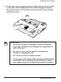
WARNINGS must be followed carefully to avoid damage
to your printer and computer.
CAUTIONS should be followed carefully to ensure that
your printer operates correctly.
Notes contain important information and useful tips on the
operation of your printer.
2
About This Manual
Chapter 1
Setting Up the Printer
Unpacking the Printer .............................................................
Checking the parts ...............................................................
1-2
1-2
Choosing a Place for the Printer . . . . . . . . . . . . . . . . . . . . . . . . . . . . . . . . . . . . . . . 1-4
Assembling the Printer ............................................................
Installing the platen knob.. .................................................
Installing the ribbon cartridge.. ..........................................
Attaching the paper guide ..................................................
1-7
1-7
1-8
1-13
Testing the Printer.. .................................................................
Plugging in the printer.. ......................................................
Running the self test.. .........................................................
Printing problems and solutions ........................................
1-15
1-15
1-17
1-24
Connecting the Printer to Your Computer.. ......................... 1-26
The parallel interface.. ......................................................... 1-26
Setting Up Your Application Software ................................. 1-29
Choosing from a menu ........................................................ 1-29
Setting Up the Printer
1-1
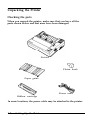
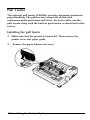
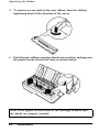
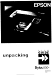
Unpacking the Printer
Checking the parts
When you unpack the printer, make sure that you have all the
parts shown below and that none have been damaged.
Printer
sa
Platen knob
Paper guide
Power cable
Ribbon cartridge
In some locations, the power cable may be attached to the printer.
1-2
Setting Up the Printer
Unpacking the Printer
I! ! !9
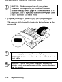
WARNING: There are several different versions of the
printer designed for different electrical standards. The
power supply voltage is shown on the label on the back
of the printer. If the voltage shown is not the correct
voltage for your country, contact your dealer. It is not
possible to adjust the printer for use with different
voltages.
After removing the parts, save the packaging materials in case you
ever need to transport your printer.
Setting Up the Printer
1-3
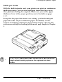
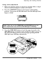
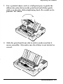
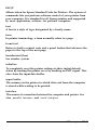
Choosing a Place for the Printer
There are several important things to consider when selecting the
place to set up your printer. Be sure to keep the following in mind:
l
l
l
l
Place the printer on a flat, stable surface.
Place the printer close enough to the computer for the printer
cable to reach.
Leave adequate room around the printer to allow easy printer
operation and maintenance.
Use a grounded outlet; do not use an adapter plug.
B
l
l
l
1-4
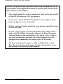
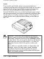
WARNING: Avoid locations that are subject to direct
sunlight, excessive heat, moisture, or dust.
I
Avoid electrical outlets controlled by wall switches or
automatic timers. Accidental interruption of power can wipe
out information in your computer’s and printer’s memory.
Avoid outlets on the same circuit with large motors or electrical
appliances that might cause fluctuations in line voltage.
Keep the entire computer system away from potential sources
of electromagnetic interference such as loudspeakers or the base
units of cordless telephones.
Setting Up the Printer
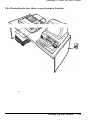
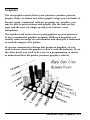
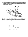
Choosing a Place for the Printer
The illustration below shows a good printer location.
r
Setting Up the Printer
1-5
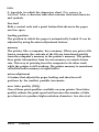
Choosing a Place for the Printer
Note: If you plan to use a printer stand, read through the list of
requirements and suggestions below to ensure that you have the
right stand for your printer.
l
l
l
l
l
1-6
The stand should be able to support at least twice the weight
of the LX-810 printer (11.5 kg approx).
Never use a stand that tilts the printer at an angle of more
than 15 degrees from horizontal.
With a cut sheet feeder installed, your printer should be kept
level at all time.
If your paper supply is positioned below the printer stand,
make sure that there is enough clearance to keep the paper
from catching on the underside of the stand. Also, check to
see that the distance between the stand supports is wide
enough to accommodate the paper you will be using.
Position your printer’s power cable and I/F cable so that
they do not interfere with paper feeding. If possible, secure
the cables to the printer stand support.
Setting Up the Printer
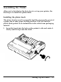
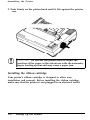
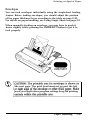
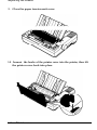
Assembling the Printer
After you’ve decided on the best place to set up your printer, the
first step is to install the platen knob.
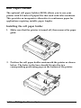
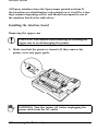
Installing the platen knob
The platen knob is used to manually feed the paper in the event of
a paper jam or other paper feeding problem. You will find the
platen knob packed in an indentation in the white foam packaging
material.
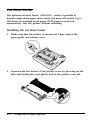
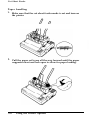
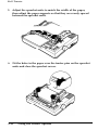
1. Insert the knob into the hole on the printer’s side and rotate it
slowly until it slips onto the shaft.
Setting Up the Printer
1-7
Assembling the Printer
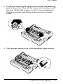
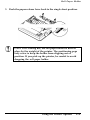
2. Push firmly on the platen knob until it fits against the printer
case.
a
I
CAUTION: Do not use the platen knob to adjust the
position of the paper as this interferes with the automatic
paper loading system and may cause a paper jam.
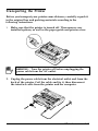
Installing the ribbon cartridge
Your printer’s ribbon cartridge is designed to allow easy
installation and removal. Before installing the ribbon cartridge,
make sure that the printer is not plugged in an electrical outlet.
1-8
Setting Up the Printer
Assembling the Printer
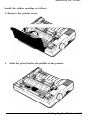
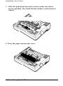
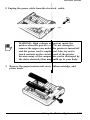
Install the ribbon cartridge as follows.
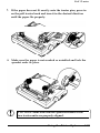
1. Remove the printer cover.
2. Slide the print head to the middle of the printer.
Setting Up the Printer
1-9
Assembling the Printer
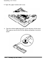
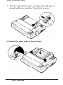
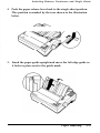
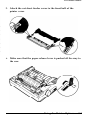
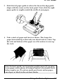
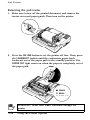
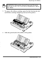
3. Open the paper tension unit cover.
4. Turn the ribbon-tightening knob in the direction of the arrow.
This removes excess slack in the ribbon and makes it easier to
install.
1-10
Setting Up the Printer
Assembling the Printer
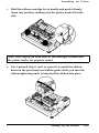
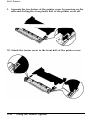
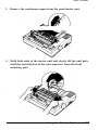
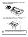
5.
Hold the ribbon cartridge by its handle and push it firmly
down into position, making sure the plastic hooks fit in the
slots.
Note: Press lightly on both ends of the cartridge to make sure
the plastic hooks are properly seated.
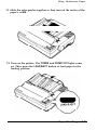
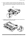
6.
Use a pointed object, such as a pencil, to guide the ribbon
between the print head and ribbon guide while you turn the
ribbon-tightening knob to help feed the ribbon into place.
Setting Up the Printer
1-11
Assembling the Printer
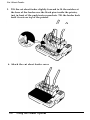
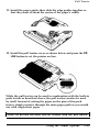
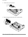
7. Slide the print head from side to side to make sure that it
moves smoothly. Also check that the ribbon is not twisted or
creased.
8. Close the paper tension unit cover.
1-12
Setting Up the Printer
Assembling the Printer
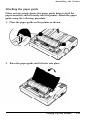
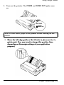
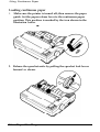
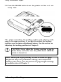
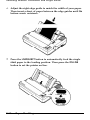
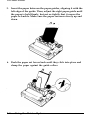
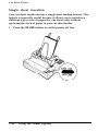
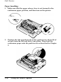
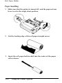
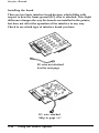
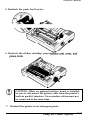
Attaching the paper guide
When you use single sheets, the paper guide helps to feed the
paper smoothly and efficiently into the printer. Attach the paper
guide using the following procedure.
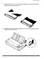
1. Place the paper guide on the printer as shown.
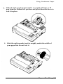
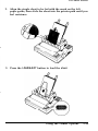
2. Raise the paper guide until it locks into place.
Setting Up the Printer
1-13
Assembling the Printer
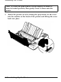
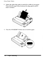
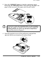
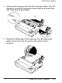
Note: To lower the paper guide, lift up slightly to release it
from its locked position, then gently lower it down onto the
printer.
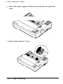
3. Attach the printer cover by fitting the projections on the cover
into the notches at the front of the printer and tilting the cover
back into place.
1-14
Setting Up the Printer
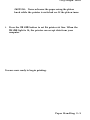
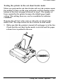
Testing the Printer
Now that your printer is fully assembled, you can use its built-in
self test function to see that the printer is working correctly before
you connect it to a computer. You should perform this test to
make sure that your printer was not damaged during shipping and
that the ribbon is correctly installed.
Before running the self test, you need to plug in the printer and
load paper.
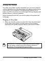
Plugging in the printer
1. Make sure that the printer is turned off. Then check the label
on the back of the printer to make sure the power rating
required by the printer matches that of your electrical outlet.
WARNING: If the rated voltage and your outlet voltage
do not match, contact your nearest Epson dealer for
assistance. Do not plug in the power cable.
Setting Up the Printer
1-15
Testing the Printer
2.
Connect the power cable to the AC inlet on the printer’s rear
panel. (In some locations, the power cable is already connected
to the printer.)
3.
Plug the power cable into a properly grounded electrical outlet.
1-16
Setting Up the Printer
Testing the Printer
Running
the self test
The self test can be run in draft or Near Letter Quality (NLQ)
mode, depending on which button you hold down as you turn on
the printer.
1. Make sure that the printer is turned off. Then push the paper
release lever back to the single-sheet position.
2. While holding down the LINE FEED button (draft font) or FORM
FEED button (NLQ fonts), turn on the printer. The POWER and
PAPER OUT lights come on.
Setting Up the Printer
1-17
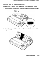
Testing the Printer
3. Move the left edge guide so that it locks in place next to the
guide mark.
4. Adjust the right edge guide to match the width of your paper.
Next, slide a sheet down between the edge guides until it
meets resistance.
WARNING: Run the self test using paper wider than A4
(81/4 inches or 210 mm) or letter size (BY2 inches or 216
mm), to prevent the print head from printing directly
onto the platen.
1-18
Setting Up the Printer
Testing the Printer
5. Press the LOAD/EJECT button to load paper.
LOAD/EJECT
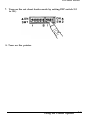
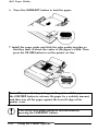
6. Press the ON LINE button to start the self test. A list of DIP
switch settings is printed first, followed by a series of
characters. The self test continues until the paper runs out or
until you press the ON LINE button.
Setting Up the Printer
1-19
Testing the Printer
7. If the test results are satisfactory and you wish to stop the test,
press the ON LINE button. If the test results are not satisfactory,
see printing problems and solutions later in this chapter,
Note: To resume the test, press the ON LINE button once more.
8. If the paper is still loaded, press the LOAD/EJECT or LINE FEED
button to eject it and turn off the printer.
LOAD/EJECT
I! ! !9
WARNING: After turning the power off, always wait at
least five seconds before turning it back on. Turning the
power on and off rapidly can damage the printer.
1-20
Setting Up the Printer
Testing the Printer
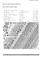
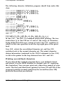
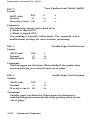
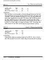
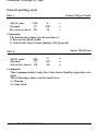
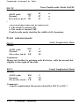
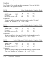
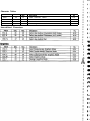
Here are parts of typical self tests:
Draft mode (normal draft)
l-l OFF
10 CPI
Character Spacing
1-2 OFF
0
(Unslashed)
Shape of Zero
1-3
OFF
Italics
CG Table
1-4
OFF
Valid
Short Tear-off
1-S ON
Normal
Draft Print Speed
1-6 ON
U.S.A.
Country
2-1 OFF
11 inch
Page Length
2-2 OFF
Invalid
CSF Mode
2-3
OFF
None
Skip Perforation
2-4
OFF
Depend on I/F
Auto LF
i "#$%& ' ( ) f-l- r - I /t]12345&.789 : ; .<==...'~."?@ABCDEFGHI J KL
! "#$%&' ( )#+,-./0123456789: j ':,--..
"-'.?@ABCDEFGHIJKLE
"#$:/.&' ( )*+,--.,'(:)123456789: ;.:::=:::.?CdABCDEFGHIJKLMP
i#$%&' ( ) #t-k, --. /<:11’L:34~&‘789: ; &:3 ?QAECDEF'GHIJt(::LMNC
'-x.?@AECDEFGHIJKLMNOF
S%& ' ( ) *-+ !, -- . ,‘Q123456789: ; x.-...
~'--."..'?~ABCDEFGHI J KLMNOFC
%B' ()*+,-. /(:~12:~45&789 : ; x,--...
o'-~x.p~(iifiB~DEFGH J, J k;LMNOPfYjf
: ; ..I.--...
h' ( ) *"s'- . ;I(-',. .j.I."3?456789
...a
"-‘~.'~;@t!,T-(CDEF'GH
1 J CjJ-jNOFfJF(E
/012345&789
:
j
.
.
..I...
' i :o+,-.
( j f + !, --. /(:>12345&789: ; .:::=)3@ABCDEFGHIJKLMNOPtK?3
:
) 8;. r" . /(]12345&7G9 e ; .$+.? @ABCDEFGHIJKLMNOFQRST1
s-k. ;.- ~ ,/<~)1234=J6’789: ; .;;+.'? BAECDEFGHIJI<LMNOF'~RSTU\
..I. "_ /(")1'7'~4ri6.789
- =,.c:=::~?QABCT)EFGIiIJKLMNOF~MSTUVk
,
A.1 %"
.'.
.
;(~)&;4~~'789:
;
.:::-;..;'
.:~@AECDEFGHIJKLMNOPQRSTUVW)
?
- . ,/i'j12345,$"78r+:
;
.(=z
b /
...
"?@AtiCDEFGHIJELMNOFQHSTlJVWX~
. ,'<:,1,>:~45,&';78y: ; <.,.m..,.
'-"?P?ABCDEFSHIJKLMNOFQRSTUVWXY~
,/‘(;;1’73L+5&,;7~9 g ; .::=:;- 3@AECDEFGHIJ#LMNOFQWSTUVWXYZ[
(:);~2:3.$5&789 : j .:::z:::,"? @AbCDEF'GHIJELMNOFflRSTUVWXYZ['
1~!345&'7#9:: j .::E=> ?@ABODEFGHIJKLMNOFBRSTUVWXYZ~\:
c3'
__ .,
[\ 1."
A.. .:?. _ai,- 8''ic j".%.a "7, 8 cg : ; .:,.",..-"..?CaABCT)EFGHIJKLMNOFRRSTlJVWXYZ
3q.5(>'789 : j .:::z;:. ?@ABCDEFGHI JELMNOPQRSTUVWXYZ f ! I"'4 9 (3 '7 gJy : ; <:: zc: _,... ?@ABCDEF~GHIJKLMNOP~~RSTUVWXYZ f: \ I."'-.'
9 6 ‘7 8 9 : ; .;.' "L: 1:. "I:@AECDEFGHIJC::LMNOFRRSTI.JVWXYZ::\]~"-‘;
. .'
Setting Up the Printer
1-21
Testing the Printer
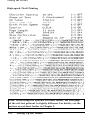
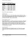
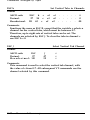
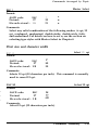
High-speed Draft Printing
Note: When using the optional cut sheet feeder, the first page
of the self test printout is slightly different. For details, see the
section on cut sheet feeder in Chapter 5.
1-22
Setting Up the Printer
Testing the Printer
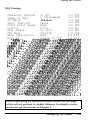
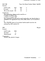
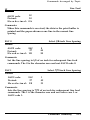
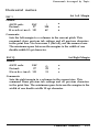
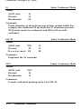
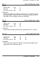
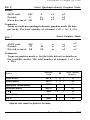
NLQ Printing
l-l OFF
10 CPI
Character Spacing
1-2 OFF
0 (Unslashed)
Shape of Zero
1-3 OFF
Italics
CG Table
1-4 OFF
Short Tear-off
Valid
1-5 OFF
Draft Print Speed
High
1-6 ON
U.S.A.
Country
2-1 OFF
Page Length.
11 inch
CSF Mode
Invalid
2-2 OFF
2-3 OFF
Skip Perforation
None
Auto LF
Depend on I/F
2-4 OFF
! I'#$%&'( )*+,- ./0123456789:;<=>?@CDEFGHIJKI
!"#$%&'()*+,-. /0123456789:;<=>?@ABCDEFGHIJKu
"#$%8c*( )*+,-. /0123456789:;c=>?@ABCDEFGHIJK~
#$%&*()*+,- ./0123456789:;c=>?@ABCDEFGHIJKLMNC
$%&'()*+,-. /0123456789:;<=>?@ABCDEFGHIJKLMNOE
%&'( )a+,- ./0123456789:;<=>?@ABCDEFGHIJKLMNOP6
%'()X+,-. /0123456789:;<=>?8ABCDEFGHIJKLMNOPQF
'(I*+,- ./0123456789:;<=>?@DEFGHIJKLMNOPQ~
(I*+,- ./0123456789:;<=>?8ABCDEFGHIJKLMNOPQRSI
I*+,- ./0123456789:;<=>?@ABCDEFGHIJKLMNOPQRST~
*+,- ./0123456789:;<=>?@ABCDEFGHIJKLMNOPQRSTU%
+,-. /0123456789:;<=>?@ABCDEFGHIJKLMNOPQRS~
,-./0123456789:;<=>?@ABCDEFGHIJKLMNOPQRSTUVWl!
-./0123456789:;~=~?@ABCDEFGHIJKLMNOPQRSTWWX1
./0123456789:;<=>?@ABCDEFGHIJKLMNOPQRSTWWXYZ
/0123456789:;<=>?@ABCDEFGHIJKLMNOPQRSTWWXYZ[
0123456789:;<=>?@ABCDEFGHIJKLMNOPQRSTUVWYZC\
123456789:;<=>?@ABCDEFGHIiJKL,MNOPQRSTWWXYZ[\l
23456789:;<=>?@ABCDEFGHIJKLMNOPQRSTWWXYZ[\l3456789:;<=>?@ABCDEFGHIJKLMNOPQRSTWWXYZ[\]*~
456789:;<=>?@ABCDEFGHIJKLMNOPQRSTWWXYZ[\]--*
56789:;<=>?@ABCDEFGHIJKLMNOPQRSTUVW2tYZ[\]n~~~
Note: When using the optional cut sheet feeder, the first page
of the self test printout is slightly different. For details, see the
section on cut sheet feeder in Chapter 5.
Setting Up the Printer
1-23
Testing the Printer
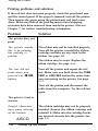
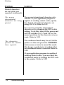
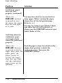
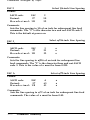
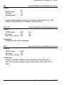
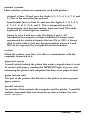
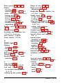
Printing problems and solutions
If the self test does not print properly, check the print head area
and the control panel. If the paper is jammed, turn off the printer.
Then remove the paper using the platen knob and load a new
sheet. Make sure that all the packing material and shipping
restraints have been removed from inside the printer. Also see
Chapter 7 for further troubleshooting information.
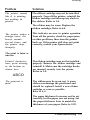
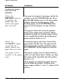
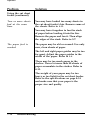
Problem
Solution
The printer does not
print.
The printer sounds
like it is printing,
but nothing is
printed.
The ribbon may not be installed properly.
Turn off the printer, reinstall the ribbon
cartridge and take up any slack in the
ribbon. See page 1-8.
The ribbon may be worn. Replace the
ribbon cartridge. See page 6-4.
The test did not
print when you
pressed the ON LINE
button.
Turn off the printer and repeat the self
test. Make sure you hold down the FORM
FEED or LINE FEED button the entire time
you are turning on the printer. See page
1-17.
Turn off the printer and disconnect the
cable from the computer. Try the self test
again.
The print is faint or
uneven.
Printed characters
have parts missing
at the bottom.
ABCD
1-24
The ribbon cartridge may not be properly
installed. Remove the ribbon cartridge and
reinstall it. Make sure the cartridge hooks
are inserted securely into the printer. See
page 1-8.
Setting Up the Printer
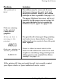
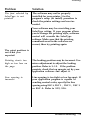
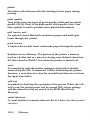
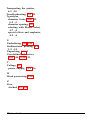
Testing the Printer
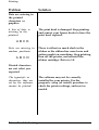
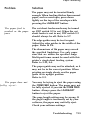
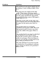
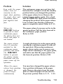
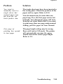
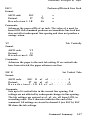
Problem
Solution
The printout is
faint.
The ribbon may be worn out. A worn
ribbon can damage the print head and
should be replaced. Install a new ribbon
cartridge as soon as possible. See page 6-4.
The paper thickness lever may not be set
correctly for the paper you are using. Set
the paper thickness lever to match the
thickness of your paper. See page 2-22.
Dots are missing
in the printed
characters or
graphics.
A line of dots is
missing in the
printout.
The print head is damaged. Stop printing
and contact your Epson dealer or Epson
authorized service center to have the print
head replaced.
Dots are missing in
random positions.
There is either too much slack in the
ribbon or the ribbon has come loose and
caught on something. Stop printing, turn
off the printer, and reinstall the ribbon
cartridge. See page 1-8.
A B C D
If the printer still does not print the self test correctly, contact
your Epson dealer or Epson authorized service center.
Setting Up the Printer
1-25
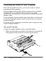
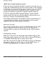
Connecting the Printer to Your Computer
If the self test printed correctly, you are now ready to connect
your printer to the computer.
If your computer has a parallel interface and you have a suitable
shielded cable, you should be able to connect your printer
immediately. The steps below describe how to connect the parallel
interface cable.
If your computer requires another type of interface, you will need
to install an optional interface board. See the section on interface
boards in Chapter 5.
If you are not sure which type of interface cable is required, refer
to your computer manual.
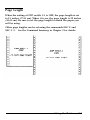
The parallel interface
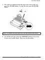
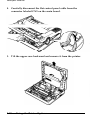
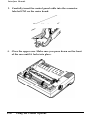
Connect the parallel interface cable as described below:
1. Make sure that both your printer and computer are turned off.
Then plug the cable connector securely into the printer.
1-26
Setting Up the Printer
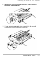
Connecting the Printer to Your Computer
2. Squeeze the wire clips together until they lock in place on
either side of the connector.
3. If your cable has a ground wire, connect it to the ground
connector beneath the interface connector.
Setting Up the Printer
1-27
Connecting the Printer to Your Computer
4.
Plug the other end of the cable into the computer. If there is a
ground wire at the computer end of the cable, attach it to the
ground connector at the back of the computer.
1-28
Setting Up the Printer
Setting Up Your Application Software
Now you have set up and tested the LX-810, you should make
sure that it works with your application programs.
Most application programs let you specify the type of printer you
are using so that the program can take full advantage of the
printer’s features. Many of these programs provide an installation
or setup menu that presents a list of printers to choose from. If
your application program has a printer selection menu, use the
instructions below.
Choosing from a menu
Because the family of Epson printers shares a great many
commands, you can use an application program even if it does not
list the LX-810 on its printer selection menu. If the LX-810 is not
listed, choose one of the following printers. They are listed in
order of preference.
LX-800
LX-86
LX-80
FX-850
FX-86e
EX-800
FX-85
FX-80+
FX-80
Setting Up the Printer
1-29
Setting Up Your Application Software
If none of these printers is listed, select the first one available on
the following list:
LX
FX
EX
RX
MX
Epson printer
Standard printer
Draft printer
To use all of the features of the LX-810, however, it is best to use
a program with the LX-810 on its menu. If your program does not
list any LX printers, contact the software manufacturer to see if an
update is available.
1-30
Setting Up the Printer
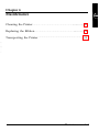
Chapter 2
Paper Handling
Using Single Sheets ................................................................. 2-2
Loading paper ....................................................................... 2-2
Reloading the paper ...................................... . .................... ..2- 6
Using Continuous Paper ......................................................... 2-7
Positioning your continuous paper supply.. .................... 2-7
Loading continuous paper ................................................... 2-8
Switching Between Continuous and Single Sheets ............ 2-15
Switching to single sheets ................................................... 2-15
Switching back to continuous paper ................................. 2-19
Printing on Special Paper ........................................................
The paper thickness lever ...................................................
Multi-part forms .................................................................
Labels .....................................................................................
Envelopes ..............................................................................
2-22
2-22
2-25
2-26
2-27
Paper Handling 2-1
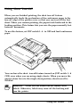
Using Single Sheets
Your printer can accommodate single sheets with a width of 7.2
inches or 182 mm to 10.1 inches or 257 mm.
If you do most of your printing on single sheets, you may find it
more convenient to install the optional cut sheet feeder. This
option automatically inserts a new sheet and can hold up to 150
sheets of standard bond paper (22 lb paper). For more details, see
Chapter 5.
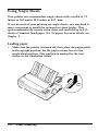
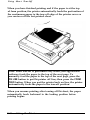
Loading paper
1. Make sure the printer is turned off, then place the paper guide
in the upright position. Set the paper release lever to the
single-sheet position. This position is marked by the icon
shown in the illustration below.
2-2
Paper Handling
Using Single Sheets
2. Turn on the printer. The POWER and PAPER OUT lights come
on.
I PAPER OUT
Note: Do not insert paper in the printer before turning on the
printer.
1
3. Move the left edge guide so that it locks in place next to the
guide mark. (You may want to change this position later,
depending on the margin settings of your application
program.)
Paper Handling 2-3
Using Single Sheets
4. Adjust the right edge guide to match the width of your paper.
Then slide the paper down between the edge guides until it
meets resistance.
5. Press the LOAD/EJECT button once to load the paper.
2-4
Paper Handling
Using
Single Sheets
CAUTION: Never advance the paper using the platen
knob while the printer is switched on. If the platen turns
6. Press the ON LINE button to set the printer on line. When the
ON LINE light is lit, the printer can accept data from your
computer.
You are now ready to begin printing.
Paper Handling 2-5
Using Single Sheets
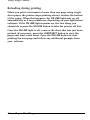
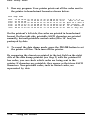
Reloading during printing
When you print a document of more than one page using single
sheet paper, the printer stops printing when it reaches the bottom
of the paper. When this happens, the ON LINE light may go off
automatically or it may remain on, depending on your application
software. If the ON LINE light remains on, the first thing you
should do is press the ON LINE button to take the printer off line.
Once the ON LINE light is off, remove the sheet that has just been
printed (if necessary, press the LOAD/EJECT button to eject the
page) and load a new sheet. Press the ON LINE button to start
printing the next page and follow any additional prompts from
your software.
2-6
Paper Handling
Using Continuous Paper
The push tractor built into your printer is remarkably easy to load
and operate. Its low-profile design takes up little space and can
handle paper widths from 4 inches or 101 mm to 10 inches or 254
mm.
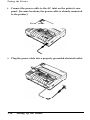
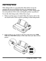
Positioning your continuous paper supply
An important consideration for achieving smooth and accurate
paper feeding is the position of your paper supply.
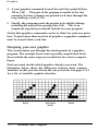
Three ways of positioning your printer and continuous paper
supply are shown below.
Make sure you align the paper supply evenly with the paper
loaded in the tractor so the paper feeds smoothly into the printer.
Paper Handling 2-7
Using Continuous Paper
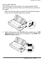
Loading continuous paper
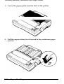
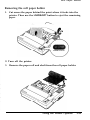
1. Make sure the printer is turned off; then remove the paper
guide. Set the paper release lever to the continuous paper
position. This position is marked by the icon shown in the
illustration below.
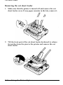
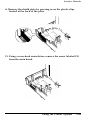
2. Release the sprocket units by pulling the sprocket lock levers
forward as shown.
2-8
Paper Handling
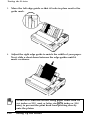
Using Continuous Paper
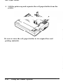
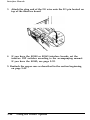
Slide the left sprocket unit until it is roughly 1/2 inch or 15
mm from the farthest left position and press down the lever to
lock it in place.
4. Slide the right sprocket unit to roughly match the width of
your paper but do not lock it.
Paper Handling 2-9
Using Continuous Paper
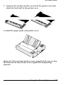
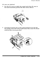
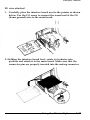
5. Move the paper support midway between the two sprocket
units.
6.
Open both sprocket covers.
2-10
Paper Handling
Using Continuous Paper
of both
CAUTION: Make sure that your paper has a clean,
straight edge before inserting it into the printer.
8. Close the sprocket covers.
Paper Handling
2-11
Using Continuous Paper
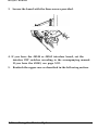
9. Slide the right sprocket unit to a position where the paper is
straight and has no wrinkles. Then lock it in place.
10.
2-12
Reattach the paper guide as shown below.
Paper Handling
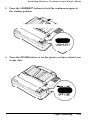
Using Continuous Paper
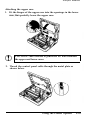
11. Slide the edge guides together so they meet at the center of the
paper’s width.
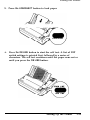
12. Turn on the printer. The POWER and PAPER OUT lights come
on. Then press the LOAD/EJECT button to feed paper to the
loading position.
Paper Handling
2-13
Using Continuous Paper
13. Press the ON LINE button to set the printer on line so it can
accept data.
The printer remembers the loading position and advances each
page to the same position. If you need to adjust the loading
position, use the micro-adjustment feature. See the section on
adjusting the loading position in Chapter 3.
CAUTION: Never adjust the loading position using the
platen knob, and never turn the platen knob while the
printer is turned on.
Note: Before you begin printing, be sure to check the page
length and skip over perforation settings, and readjust the
settings if necessary. See the sections on page length and skip
over perforation in Chapter 3.
2-14
Paper Handling
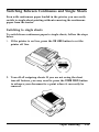
Switching Between Continuous and Single Sheets
Even with continuous paper loaded in the printer, you can easily
switch to single-sheet printing without removing the continuous
paper from the tractor.
Switching to single sheets
To switch from continuous paper to single sheets, follow the steps
below.
1. If the printer is on line, press the ON LINE button to set the
printer off line.
2. Tear off all outgoing sheets. If you are not using the short
tear-off feature, you may need to press the FORM FEED button
to advance your document to a point where it can easily be
removed.
Paper Handling
2-15
Switching Between Continuous and Single Sheets
CAUTION: Make sure you tear off your printed
document before pressing the LOAD/EJECT button.
3. Press the LOAD/EJECT button to feed the continuous paper
backward out of the printer and into the standby position.
The paper is still attached to the tractor but no longer in the
paper path.
CAUTION: If you are using narrow paper less than 6
inches or 152.4 mm wide, you should only press the
LOAD/EJECT button once. Also, do not use this button to
eject labels.
WARNING: Never feed labels backward through the
printer. Labels can easily come off the backing sheet and
jam the printer.
2-16
Paper Handling
Switching Between Continuous and Single Sheets
4. Push the paper release lever back to the single-sheet position.
This position is marked by the icon shown in the illustration
below.
5. Stand the paper guide upright and move the left edge guide so
it locks in place next to the guide mark.
Paper Handling
2-17
Switching Between Continuous and Single Sheets
6.
Adjust the right edge guide to match the width of your paper.
Then insert a sheet of paper between the edge guides until the
bottom meets resistance.
7. Press the LOAD/EJECT button to automatically feed the single
sheet paper to the loading position. Then press the ON LINE
button to set the printer on line.
2-18
Paper Handling
Switching Between Continuous and Single Sheets
Switching
back to continuous paper
It is also easy to switch back to printing with continuous paper.
1. Make sure the single sheet is ejected and the printer is off line.
2. Slide the edge guides together so they meet at the center of the
paper’s width.
Paper Handling
2-19
Switching Between Continuous and Single Sheets
3. Lower the paper guide onto the back of the printer,
4. Pull the paper release lever forward to the continuous paper
position.
2-20
Paper Handling
Switching Between Continuous and Single Sheets
5. Press the LOAD/EJECT button to feed the continuous paper to
the loading position.
6. Press the ON LINE button to set the printer on line so that it can
accept data.
Paper Handling
2-21
Printing on Special Paper
In addition to printing on single sheets and continuous paper, your
printer can also print on a wide variety of paper types, including
multi-part forms, labels, and envelopes.
Before printing on special types of paper, you need to change the
paper thickness setting.
WARNING: When printing on multi-part forms, labels, or
envelopes, make sure your application program settings
keep the printing entirely within the printable area.
For multi-part forms and labels, you should not print any
closer than 0.5 inches or 13 mm from either side of the
paper.
For information on the printable area for envelopes, see
page 2-29.
The paper thickness lever
To accommodate various thicknesses of paper, your printer is
equipped with a paper thickness lever that can be set to seven
positions. These positions are identified by a scale next to the
lever.
2-22
Paper Handling
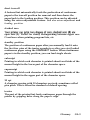
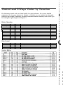
Printing on Special Paper
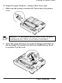
To change the paper thickness setting, follow these steps.
1. Make sure the printer is turned off. Then remove the printer
cover.
WARNING: If the printer has just been in use, the print
head may be hot. Allow it cool before touching it.
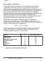
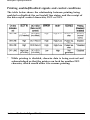
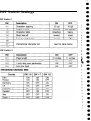
2. Select the paper thickness you want according to the table on
the next page. For normal use, the lever should always be set
to position 2 on the scale.
Paper Handling
2-23
Printing on Special Paper
Lever Position
Paper Type
Paper (single sheets or continuous)
2
Thin paper
2
24 lb paper (single sheets)
I
Multi-part forms
2-sheet
3-sheet
Labels
3
2
3
I
4
Envelopes
Air mail
Plain
Bond (20 lb.)
Bond (24 lb.)
4 or 5
6
6
7
3. Attach the printer cover.
I!!!3
WARNINGS:
l
Always return the lever to position 2 when you go
back to printing on ordinary paper. Continuous
printing with the lever set at a position higher than 2
can shorten the life of the print head.
l
2-24
Printing past the edge of envelopes, multi-part forms,
labels, or thicker than normal paper can damage the
print head.
Paper Handling
Printing on Special Paper
Multi-part forms
With the built-in tractor unit, your printer can print on continuous
multi-part forms. You can use multi-part forms that have up to
three parts (including the original). Make sure you set the paper
thickness lever to the proper position; see to the table on page
2-25.
Except for the paper thickness lever setting, you load multi-part
paper the same way as continuous paper. For details, see the
section on loading continuous paper in this chapter. Also see the
sections on setting the loading position and page length in Chapter
3.
a
l
CAUTION: Multi-part forms should not be used with the
single sheet feeding system or the optional cut sheet
feeder.
Paper Handling
2-25
Printing on Special Paper
Labels
If you need to print labels, always use ones mounted on a
continuous backing sheet with sprocket holes made for use with a
tractor feed. Do not try to print labels as single sheets because
labels on a shiny backing sheet almost always slip a little.
You load labels the same way you load continuous paper except
that the paper thickness lever must be adjusted for printing labels.
See the section on loading continuous paper in this chapter for
details. For the correct paper thickness setting, see the table on
page 2-25.
I! ! !9
WARNING: Never feed labels backward through the
printer. Labels can easily peel off the backing and jam
the printer. Therefore, do not use the LOAD/EJECT button
to eject labels. Also, never use the short tear-off function
with labels (be sure to set DIP switch 1-4 to ON). If a
label does become stuck in the printer, contact your
dealer.
Since labels are especially sensitive to temperature and
humidity, always use them under normal operating
conditions. Don’t leave labels loaded in the printer
between jobs; they curl around the platen and may jam
when you resume printing.
2-26
Paper Handling
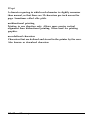
Printing on Special Paper
Envelopes
You can feed envelopes individually using the single-sheet loading
feature. Before loading envelopes, you should adjust the position
of the paper thickness lever according to the table on page 2-25.
For details on paper handling, see Using Single Sheets on page 2-2.
When manually feeding an envelope, you may have to push it
down slightly while pressing the LOAD/EJECT button to get it to
feed properly.
the next page. The print head must not go past the left
sure your application program settings keep the printing
Paper Handling
2-27
Printing on Special Paper
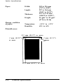
8.5 mm (0.33”)
or more
22 mm (0.87”)
or more
CAUTION: Envelope printing is only available at normal
temperature.
To make sure that the printing fits within the printable area,
always print a test sample using a normal single sheet of paper
before printing on envelopes.
2-28
Paper Handling
Chapter 3
Using the Printer
Operating the Control Panel .................................................. 3-2
3-2
Lights .....................................................................................
3-3
Buttons ..................................................................................
3-4
..............................................................................
SelecType
Other control panel features ............................................. 3-5
Setting the DIP Switches ........................................................
Changing a DIP switch setting ..........................................
The DIP switch tables .........................................................
The DIP switch functions ...................................................
3-6
3-6
3-7
3-8
Page Length . . . . . . . . . . . . . . . . . . . . . . . . . . . . . . . . . . . . . . . . . . . . . . . . . . . . . . . . . . . . . . . . . . . . . ............. 3-9
Skip Over Perforation . . . . . . . . . . . . . . . . . . . . . . . . . . . . . . . . . . . . . . . . . . . . . . . . . . . . . . . . . . . . . 3-10
Adjusting the Loading Position ........................................... . 3 - 1 2
Using micro-adjustment.. ................................................... 3 - 1 3
Using Short Tear-Off .............................................................. 3-15
Adjusting the tear-off position .......................................... 3-17
Selecting Typestyles ................................................................
Character fonts .....................................................................
Condensed mode ..................................................................
3-19
3-20
3-22
Selecting an International Character Set . . . . . . . . . . . . . . . . . . . . . . . . . . . . . 3-23
Choosing a Character Table . . . . . . . . . . . . . . . . . . . . . . . . . . . . . . . . . . . . . . . . . . . . . . . . . . . 3-25
Data Dump Mode . . . . . . . . . . . . . . . . . . . . . . . . . . . . . . . . . . . . . . . . . . . . . . . . . . . . . . . . . . . . . . . . . . . . 3-27
Using the Printer
3-1
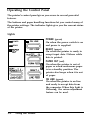
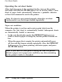
Operating the Control Panel
The printer’s control panel gives you access to several powerful
features.
The buttons and paper handling functions let you control many of
the printer settings. The indicator lights give you the current status
of the printer.
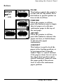
Lights
POWER (green)
POWER
- ON LINE
READY
- ZEE”
OFF LINE
On when the power switch is on
and power is supplied.
READY (green)
On when the printer is ready to
accept input data. Flickers while
data is printed.
PAPER OUT (red)
On when the printer is out of
paper or when continuous paper
is in a standby position. The
printer also beeps when it is out
of paper.
ON LINE (green)
On when the printer is on line
and ready to accept data from
the computer. When this light is
flickering, the micro-adjustment
feature can be used.
3-2
Using the Printer
Operating the Control Panel
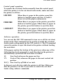
Buttons
ON LINE
0 POWER
0 ON LINE
0 READY
o PAPER
OUT
OFF LINE
This button controls the printer’s
on line and off line status. Press
this button to put the printer on
line or take it off line.
FORM FEED
FORM FEEDn
When the printer is off line,
press this button to eject a single
sheet of paper or to advance
continuous paper to the top of
the next page.
LINE FEED
LOAD/EJECT
LINE FEED
When the printer is off line,
press this button to advance the
paper one line, or hold it down
to advance the paper
continuously.
LOAD/EJECT
This button is used to feed the
paper to the loading position, or
to eject paper that is already
loaded. Paper is ejected forward
if the paper release lever is set to
the single sheet position and is
ejected backward (removed from
the paper path) if the release
lever is set to the continuous
paper position.
Using the Printer
3-3
Operating the Control Panel
SelecType
You can select the built-in character fonts using the SelecType
feature on your control panel when the printer is on line.
NLQ
0 POWER
0 ON LINE
0 READY
0 E;ER
OFF LINE
L
This button is used to select
NLQ Roman and NLQ Sans Serif
fonts, When you select Roman,
the beeper sounds two times.
When you select Sans Serif, the
beeper sounds three times.
DRAFT
This button is used to select
draft printing. When you select
draft, the beeper sounds once.
CONDENSED
This button is used to select or
deselect the condensed mode.
When you select the condensed
mode, the beeper sounds once. In
this mode all characters are
printed at approximately 60% of
their normal width. When you
return to the normal mode, the
beeper sounds twice.
Note: Condensed mode cannot be selected when either of the
NLQ fonts have been selected.
3-4
Using the Printer
Operating the Control Panel
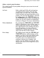
Other control panel features
The control panel of your printer also gives you access to several
special functions.
Self test:
Both a draft and NLQ self test function
are built into the printer. The self test
printout lets you check the current DIP
switch settings and operating status of the
printer. You can start the printer’s self test
by holding down the LINE FEED button or
the FORM FEED button while switching the
printer on. See the section on running the
self test in Chapter 1 for more information.
Micro-adjustment:
By pressing the FORM FEED and LINE FEED
buttons immediately after loading paper or
when using short tear-off, you can make
fine adjustments to the loading and short
tear-off positions. See the sections on
adjusting the loading position and using
short tear-off later in this chapter.
Data dump:
By holding down both the LINE FEED and
FORM FEED buttons while turning on the
printer, you turn on the data dump mode.
This feature allows advanced users to
locate the source of communications
problems between the computer and
printer. See the section on using the data
dump mode later in this chapter for more
information.
Using the Printer
3-5
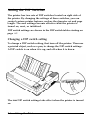
Setting the DIP Switches
The printer has two sets of DIP switches located on right side of
the printer. By changing the settings of these switches, you can
control various printer features, such as the character set and page
length. The new settings become effective when the printer is
turned on, reset, or initialized.
DIP switch settings are shown in the DIP switch tables starting on
page 3-7.
Changing a DIP switch setting
To change a DIP switch setting, first turn off the printer. Then use
a pointed object, such as a pen, to change the DIP switch settings.
A DIP switch is on when it is up, and off when it is down.
The new DIP switch settings take effect when the printer is turned
on.
3-6
Using the Printer
/
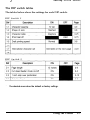
Setting the DIP Switches
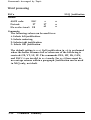
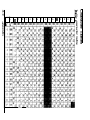
The DIP switch tables
The tables below show the settings for each DIP switch.
DIP Switch 1
DIP Switch 2
.
The shaded areas show the default or factory settings.
Using the Printer
3-7
Setting the DIP Switches
International character sets
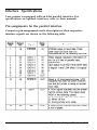
The DIP switch functions
Slashed zeros
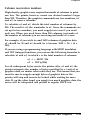
When DIP switch 1-2 is ON, the printer prints slashed zeros(ø);
when OFF, the printer prints open zeros (0). This feature is useful
for clearly distinguishing between uppercase 0 and zero when
printing documents such as program lists.
Draft printing speed
When DIP switch 1-5 is OFF, the printer can print up to 200 draft
characters per second; when ON, the printer can print up to 150
characters per second. The high speed setting is effective only
when printing at 10 cpi (characters per inch). When printing at a
different pitch, this switch is ignored and the printer prints up to
150 characters per second.
Auto line feed
When auto line feed is ON (DIP switch 2-4 ON), each carriage
return code (CR) is automatically followed by a line feed code
(LF)*
3-8
Using the Printer
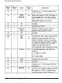
Page Length
When the setting of DIP switch 2-1 is OFF, the page length is set
to 11 inches (27.94 cm). When it is on, the page length is 12 inches
(30.48 cm). Be sure to set the page length to match the paper you
will be using.
Other page lengths can be set using the commands ESC C and
ESC C 0. See the Command Summary in Chapter 9 for details.
Using the Printer
3-9
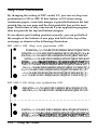
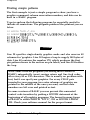
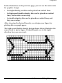
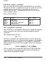
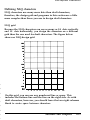
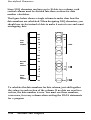
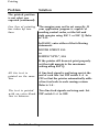
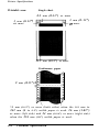
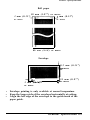
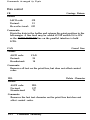
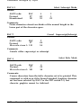
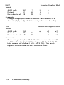
Skip Over Perforation
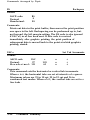
By changing the setting of DIP switch 2-3, you can set skip over
perforation to ON or OFF. If this feature is ON when using
continuous paper, a one-inch margin is provided between the last
printed line on one page and the first printable line on the next
page. This feature is very convenient if your application program
does not provide for top and bottom margins.
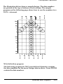
If you adjust your loading position correctly, you can get half of
the margin at the bottom of one page and half at the top of the
next page, as shown in the following illustration.
DIP SW2-3 OFF (Skip over perforation OFF)
l
23456769:;<=>?@ABCDEFGHIJKLMNOPQRSTWW
3456789:;<=>?@ABCDEFGHIJKLMNOPQRSTUVwK
456789:;<=>?@ABCDEFGHIJKIMNOPQRSTWWKY
56789:;<=>?@ABCDEFGHIJKLMNOPQRSTWWKYZ
- - - 6789~;~=>?W3CDEFGHIJKfrMNOPQRSTWWKYZC
- - - - - - - - - - - _ - - - _ _
789:;~=~?@ABCDEFGHIJKLMNOPQRSTWWKYZ~\
89:;<=~?@ABCDEFGHIJKLMNOPQRSTUVWKYZ[\J
9:;<=>?@ABCDEFGHIJKLMNOPQRSTWWKYZC\3^
:;<=>?@ABCDEFGHIJKLMNOPQRSTWWKYZ[\J-;c=>?SABCDEFGHIJKI&lNOPQRSTUWKYZ[\]--’
4B
l
l
DIP SW2-3 ON (Skip over perforation ON)
3-10
*
23456789:;<=>?@ABCDEFGHIJKLMNOPQRSTUW
3456789:;<=>?@ABCDEFGHIJKLMNOPQRSTUVW
m
456789:;<=>?@ABCDEFGHIJKLMNOPQRSTWWKY
56769:;<=>?@ABCDEFGHIJKLMNOPQRSTWWKYZ
6789:;<=>?@ABCDEFGHIJKL&lNOPQRSTWWYZC
Using the Printer
Skip Over Perforation
Note: Most application programs take care of top and bottom
margins. Only use skip over perforation if your program does
not provide these margins.
The skip over perforation setting can be set to values other than
one inch by using the ESC N command. See the Command
Summary in Chapter 9 for details.
Using the Printer
3-11
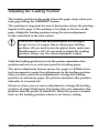
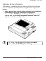
Adjusting the Loading Position
The loading position is the point where the paper stops when you
load paper using the LOAD/EJECT button.
This position is important because it determines where the printing
begins on the page. If the printing is too high or too low on the
page, change the loading position using the micro-adjustment
feature described in the next section.
CAUTION: Never use the platen knob to feed paper
except in case of a paper jam or other paper feeding
problem. (If you need to use the platen knob, make sure
that the power is off.) If you need to adjust the loading
position, always use the micro-adjustment feature.
Until the loading position is reset, the printer remembers this
position and uses it as a reference point for feeding paper.
The micro-adjustment feature moves the paper in 2/216th-of-aninch increments to make fine adjustments to the loading position.
Once you have used micro-adjustment to change the loading
position of continuous paper, the printer remembers that position
even after it is turned off.
However, when you use micro-adjustment to change the loading
position of single sheet paper, the printer does not remember this
position after the power is turned off. When the power is turned
back on, the loading position returns to its factory setting.
3-12
Using the Printer
Adjusting the Loading Position
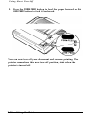
Using micro-adjustment
1. Make sure that the printer is turned on and that either a single
sheet or continuous paper is ready to be loaded.
2. Press the LOAD/EJECT button to feed paper to the loading
position. Then press the ON LINE button; the ON LINE light then
begins to blink.
:X-JO N L 1 N E
a
OFF LINE
Note: You can use the FORM FEED and LINE FEED buttons for
micro-adjustment only while the ON LINE light is blinking.
3. Press the FORM FEED button to feed the paper forward or the
LINE FEED button to feed the paper backward. When you’ve set
the desired loading position, you can begin printing; the ON
LINE light stops blinking automatically.
Using the Printer
3-13
Adjusting the Loading Position
Note: When the paper reaches the factory-set loading position,
the printer beeps and micro-adjustment feeding pauses for a
moment before continuing. You can use this position as a
reference point when adjusting the printer’s loading position.
When the paper reaches either the minimum or maximum top
margin, the printer beeps and the paper stops moving.
SelecType is not available when the ON LINE light is blinking. If
you want to use SelecType, you must press the ON LINE button
once to set the printer off line and once more to set the printer on
line.
3-14
Using the Printer
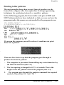
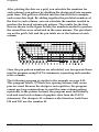
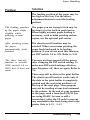
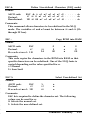
Using Short Tear-Off
When you are finished printing, the short tear-off feature
automatically feeds the perforation of the continuous paper to the
tear-off edge of the printer cover so that you can tear off the last
sheet. When you resume printing, the paper feeds backward to the
loading position. This feature lets you save the paper normally lost
between documents.
To use this feature, set DIP switch 1-4 to OFF and load continuous
paper.
ONA
SW2
You can leave the short tear-off feature turned on (DIP switch 1-4
OFF) even when you are using single sheets. When you move the
paper release lever to the single sheet position, short tear-off is
disabled.
WARNING: Never use the short tear-off feature with
labels. Otherwise, labels may come off the backing and
jam the printer.
Using the Printer
3-15
Using Short Tear-Off
When you have finished printing and if the paper is at the top
of form position, the printer automatically feeds the perforation of
the continuous paper to the tear-off edge of the printer cover so
you can tear off the last printed sheet.
Note: Short tear-off is performed only when your application
software feeds the paper to the top of the next page. To
manually feed the paper to the top of the next page, press the
ON LINE button to put the printer off line; then press the FORM
FEED button. When you put the printer back on line, the printer
automatically feeds the paper to the tear-off position.
When you resume printing after tearing off the sheet, the paper
automatically feeds backward to the loading position before
printing begins.
3-16
Using the Printer
Using Short Tear-Off
Adjusting the tear-off position
If the paper’s perforation does not line up with the tear-off edge,
you can adjust the tear-off position using the micro-adjustment
feature.
1. Make sure the short tear-off feature is turned on so the printer
feeds paper to the tear-off position after printing the
document. The ON LINE light should begin blinking, meaning
you can now use the micro-adjustment feature to make fine
adjustments to the tear-off position.
CAUTION: You can only use the micro-adjustment
feature while the ON LINE light is blinking.
Using the Printer
3-17
Using Short Tear-Off
2. Press the FORM FEED button to feed the paper forward or the
LINE FEED button to feed it backward.
You can now tear off your document and resume printing. The
printer remembers this new tear-off position, even when the
printer is turned off.
3-18
Using the Printer
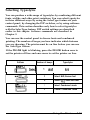
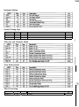
Selecting Typestyles
You can produce a wide range of typestyles by combining different
fonts, widths, and other print variations. You can select typestyles
in three different ways: by using the SelecType feature on your
control panel, by changing the DIP switches, or by using software
commands. This section describes only how to select typestyles
with the SelecType feature. DIP switch settings are described
earlier in this chapter. Software commands are described in
Chapter 9.
You can use the control panel to choose fonts and condensed
printing. The number of beeps you hear indicates which features
you are choosing. The printer must be on line before you can use
the SelecType feature.
If the ON LINE light is blinking, press the ON LINE button once to
set the printer off line and once more to set the printer on line.
I
/
c=)
1
Typestyles
Number of beeps
Buttons
Select (
I
1
draft
font
2
Select NLQ Roman font
3
Select NLQ Sans Serif font
1
Select Condensed mode
2
Cancel Condensed mode
Using the Printer
3-19
Selecting Typestyles
The settings you select using the SelecType panel remain valid
even if the printer is turned off.
Some application programs are designed to control all typestyle
functions. These programs cancel all previous typestyle settings by
sending certain software commands before printing. Because these
commands cancel SelecType settings, you should use the program’s
print options instead of SelecType to select your typestyles. If
SelecType does not work with a particular application, check the
application manual on how to select typestyles.
Character fonts
The printer has three fonts: draft, NLQ Roman, and NLQ Sans
Serif. The draft font uses fewer dots per character to allow highspeed printing, which makes it ideal for rough drafts and editing
work.
NLQ Roman and NLQ Sans Serif are Near Letter Quality (NLQ)
fonts. Near Letter Quality takes a little longer to print, but
produces nicely-formed characters suitable for most documentation
needs.
To select the draft font, press the DRAFT (LINE FEED) button when
the printer is on line. When the draft font is selected, the beeper
sounds once.
There are two printing speeds for draft font, high-speed draft and
normal draft. These printing speeds are controlled by DIP switch
1-5. See the section on setting the DIP switches in this chapter.
To select the NLQ font, press the NLQ (FORM FEED) button when
the printer is on line. When the NLQ Roman font is selected, the
beeper sounds two times. When the NLQ Sans Serif font is
selected, the beeper sounds three times.
3-20
Using the Printer
Selecting Typestyles
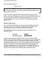
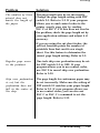
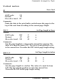
The following samples show the characters for each font.
HIGH-SPEED DRAFT
c:c2Ll.:I.~vl’t ad -f:nr
We ’ VB .:i u!3t w+xw your e x
zebras :i.n a re cxw t. ba c: Ia; :i. 5w.w of
‘1’
p r. . . .’. . ::?Q’ . . . . . I‘I’. . . . .:i. . .f,)qyzj
. . . . . .1,’. . . . ad
. . . . . . . . . z....
. . . . . . . :.z...!!.. What. i s t he p I” :i. r::e s c bed 1.1 I e
~f'or q~an I. :i. t:i. ecj c)vfi?r one CJ I-CEi!,i’?
miniature
NORMAL DRAFT
! “#%%&’ ( ) S+ .r -. /0123456789 : ; .<=>?@ABCDEFGtlI JK
LMNOFRRSTUVW XY Z [ \ ] +.-’ a b c d e f g h i j k l m n a p q r s t u v
w>:yzl; : )”
We've just seen your excellent ad for
miniature zebras in a recent back. issue of
Trader’s Times. What is the price schedule
f o r q u a n t i t i e s over o n e g r o s s ?
NLQ ROMAN
! -#$%8cc (>*+,-. /0123456789:;<=>‘?@ABCDEFGHIJK
LMNOPQRSTWWXYZC\l--’ abcdefghijklmnopqrstuv
WXYZC:
I-
W e ' v e just Been y o u r e x c e l l e n t a d f o r
miniature
zebra6 in a recent back ieeue of
.
w What is the price schedule
f o r q u a n t i t i e s over.one g r o s s ?
NLQ SANS SERIF
!“#%%&‘()S+,-./0123456769:;<=>?@~BCDEFGHIJK
LMNOPQRSTUVWXYZC\J*~’ a b c d e f g h i j k l m n o p q r s t u v
WXYZC : I”
We’ve just seen your
excellent
ad for
miniature zebras in a recent back issue of
T r a d e r ’ s T i m e s . What is the price schedule
for quantities over one gross?
Using the Printer
3-21
Selecting Typestyles
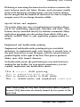
Condensed mode
You can use the condensed mode to change the character size. In
the condensed mode, characters are approximately 60% of the
width of normal characters. Hence, condensed printing is very
useful for spreadsheets and other applications where you need to
print the maximum amount of information on a page. Both 10 and
12 cpi in draft mode can be condensed but NLQ cannot.
To select or cancel condensed mode, press the CONDENSED
(LOAD/EJECT) button when the printer is on line. When the
condensed mode is selected, the beeper sounds once. When the
condensed mode is canceled, the beeper sounds two times.
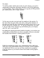
The following printout compares normal 10 and 12 cpi with
condensed 10 and 12 cpi.
This is 10 cpi printing.
This is condensed 10 cpi printing.
This is 12 cpi printing.
This is condensed 12 cpi printing.
3-22
Using the Printer
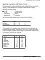
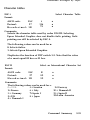
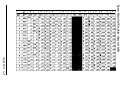
Selecting an International Character Set
International character sets provide you with the characters and
symbols used in other languages. You can select one of eight
international character sets by changing the DIP switch settings.
Whenever the printer is turned on, reset or initialized, the
character set selected by the DIP switches becomes the default
character set.
To select an international character set, set DIP switches 1-6, 1-7,
and 1-8 according to the table below.
This table also shows the characters which differ in each
international character set.
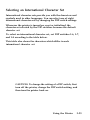
CAUTION: To change the setting of a DIP switch, first
turn off the printer, change the DIP switch setting, and
then turn the printer back on.
Using the Printer
3-23
Selecting an International Character Set
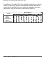
In addition to the eight DIP-switch selectable character sets shown
on the previous page, the five international character sets shown
below are also available by use of software commands. For more
information, refer to the ESC R command in Chapter 9.
Country
8
9
10
11
12
Japan
Norway
Denmark II
Spain II
Latin America
3-24
ASCII code hex
23
24
40
58
5C
50
5E
60
78
#t$@c*l-‘c
7C
I 1
7D
7E
-
#nBWBAU6s0Ati
#$184iBAU6s0AQ
#$A;t3&6‘
i A 6 13
#$&if4
i6tiiK66
Using the Printer
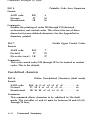
Choosing a Character Table
You can select either the italics character table or the Epson
Extended Graphics character table by setting DIP switch 1-3. The
Epson Extended Graphics character table contains international
accented characters, Greek characters, mathematic symbols, and
character graphics for printing lines, corners, and shaded areas.
If you have an IBM computer or IBM compatible, select the Epson
Extended Graphics table when you wish to print the character
graphics as they are displayed on the screen. Even if you select the
Epson Extended Graphics table, you can still print normal text and
italics. For italics, see the ESC 4 command description in Chapter 9.
Sample printouts of the italics characters and the Epson Extended
Graphics characters are shown below.
Italics
Epson Extended Graphics
Using the Printer
3-25
Choosing a Character Table
To select a character table, set DIP switch 1-3 according to the
table below.
Character table
1 Italics
Graphics
DIP SW 1-3
1 OFF
I
1 ON
I
CAUTION: To change the setting of a DIP switch, first
turn off the printer, change the DIP switch, and then
turn the printer back on.
Tables showing what characters are printed in each of the character
tables are listed in the Appendix.
3-26
Using the Printer
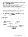
Data Dump Mode
Data dump mode is a special feature that makes it easy for
experienced users to identify the cause of communications
problems between the printer and computer. In data dump mode,
an exact printout of the codes reaching the printer is produced.
To use the data dump mode, follow these steps:
1. Make sure that paper is loaded. Either the tractor unit or the
cut sheet feeder can be used for printing in data dump mode.
2. If the printer is on, switch it off, then hold down the FORM
FEED and LINE FEED buttons at the same time you turn on the
printer.
Using the Printer
3-27
Data Dump Mode
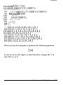
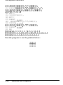
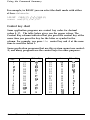
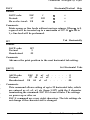
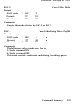
3. Run any program. Your printer prints out all the codes sent to
the printer in hexadecimal format as shown below.
Data
Dump
0000
OO1O
0020
0030
0040
0050
18
20
60
75
69
6B
Node
40
20
70
6D
73
65
1B
54
6C
70
20
73
52
68
65
20
69
20
00
69
20
70
73
69
1B
73
6F
72
20
74
74
20
66
69
66
20
01
69
20
6E
65
65
16
73
61
74
61
61
36
20
20
6F
74
73
12
61
64
75
75
79
LB
6E
61
74
72
20
50
20
74
ZE
65
66
20
65
61
20
20
6F
20
78
20
54
6D
72
20
61
64
68
61
20
[email protected]
This is an exa
mple of a data d
ump printout. Th
is is feature ma
kes it easy for
On the printout’s left side, the codes are printed in hexadecimal
format. On the right side, printable ASCII characters are printed
normally, but non-printable control codes (00 to 1F hex) are
portrayed by dots.
4. To cancel the data dump mode, press the ON LINE button to set
the printer off line. Then turn off the printer.
By comparing the characters printed in the text field on the right
side of the data dump printout (see Step 3) with the printout of
hex codes, you can check which codes are being sent to the
printer. If characters are printable, they appear as their true ASCII
characters. Non-printable codes, such as control codes, are
represented by dots.
3-28
Using the Printer
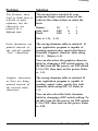
Data Dump Mode
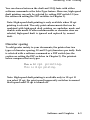
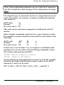
To interpret the data dump printout examine the first three hex
codes on the second line of the printout sample (20 20 54). Each
hex code 20 represents a space; hex code 54 represents the letter T.
The corresponding text field line on the right side of the printout
contains the letter T preceded by two spaces.
The chart below interprets the first six codes.
Hex codes
1B 40
1B 52 00
1B 74 01
1B 36
12
1B 50
Command
ESC @
ESC R 0
ESC t 1
ESC 6
DC2
ESC P
Function
Initialize printer
Select USA character set
Select Epson Extended Graphics character
Enable printable characters
Cancel condensed mode
Select 10 cpi
Using the Printer
3-29
Chapter 4
Software and Graphics
Enhancing Your Printing..........................................................
Print quality and fonts............................................................
Character spacing .................................................................
Character size .....................................................................
Special effects and emphasis .............................................
Selecting typestyles with Master Select ................................
4-2
4-2
4-3
4-4
4-5
4-7
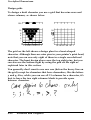
Graphics ....................................................................................
The print head.. ......................................................................
The graphics command ......................................................
Column reservation numbers....... ............................................
Printing simple patterns...... .....................................................
Printing taller patterns..... .......................................................
Designing your own graphics.... .............................................
Individual graphics commands..... ........................................
The reassignment command ..............................................
4-9
4-10
4-12
4-13
4-14
4-15
4-16
4-19
4-20
User-defined Characters . ..........................................................
Designing your characters.. .....................................................
Sending information to your printer......... ..............................
Printing user-defined characters.. ........................................
Copying ROM characters to RAM........ .................................
Mixing print styles..... .............................................................
Defining NLQ characters..... .................................................
4-21
4-21
4-23
4-24
4-25
4-26
4-27
Software and Graphics
4-1
Enhancing Your Printing
You can obtain a wide variety of printing effects with your printer,
from changing the number of characters per inch to using special
effects on selected words and phrases. This section gives you a
sampling of the features you may select with your software.
For software control of these features, see the instructions for your
applications program or look up their specific commands in
Chapter 9.
Print quality and fonts
The most apparent change you can make to print quality is to
change fonts.
Your printer has three levels of print quality: high-speed draft,
normal draft and NLQ (Near Letter Quality). High-speed draft
printing is ideal for rough drafts and large documents that you
need to print quickly. Normal draft printing is a bit slower, but
offers higher resolution characters. NLQ printing takes a little
longer, but produces darker, more fully-formed characters suitable
for presentation-quality documents. For NLQ printing, the printer
offers two fonts: Roman and Sans Serif.
The printout below shows the difference between high-speed draft,
normal draft, NLQ Roman, and NLQ Sans Serif characters so you
can compare the different styles and densities.
I-Ii g II-% pee?cl
cl ra f t
zi. III
c?ven
f as te I” I,
Draft printing is fast.
NLQ Roman is clear and typewriter-like.
NLQ
4-2
Sans
Serif is crisp
Software and Graphics
and
distinctive.
Enhancing Your Printing
You can choose between the draft and NLQ fonts with either
software commands or the SelecType feature. However, high-speed
draft printing can only be selected by setting DIP switch 1-5 (see
the section on setting the DIP switches in Chapter 3).
Note: High-speed draft printing is only available when 10 cpi
printing is selected. The only print enhancements that can be
combined with high-speed draft printing are underline mode and
double-wide mode. If other enhancements or character sizes are
selected, high-speed draft is ignored and replaced by normal
draft.
Character spacing
To add greater variety to your documents, the printer has two
types of character spacing, 10 and 12 cpi (characters per inch). Each
is selected with a software command or a DIP switch (see the
section on setting the DIP switches in Chapter 3). The printout
below compares the two types.
This is 10 cpi
12 cpi
This is
printing.
printing.
Note: High-speed draft printing is available only in 10 cpi. If
you select 12 cpi, the print speed temporarily switches to normal
draft speed until 12 cpi is turned off.
Software and Graphics
4-3
Enhancing Your Printing
Character size
In addition to the basic cpi spacings, the printer offers two other
modes that can change the size of your printing. These modes are
double-wide and condensed.
The double-wide mode doubles the width of any size character.
This mode is useful for emphasizing report headings and creating
presentations, but is usually not suitable for large amounts of text.
You can also combine double-wide mode with other enhancements
to obtain even more impressive printing results.
This is normal 10
T h i s
i s
cpi printing.
d o u b 1 e-w i d e.
Both 10 and 12 cpi printing can be reduced to about 60% of their
normal width using the condensed mode. This mode is especially
useful for printing wide spreadsheets because condensed 12 cpi
allows you to print up to 160 characters on an B-inch line.
The condensed mode can be selected with software commands or
with the SelecType feature.
Condensed 10 cpi gives you more characters on a line.
Condensed 12 cpi qives you even more.
Note: Both 10 and 12 cpi normal draft printing can be
condensed but NLQ printing cannot.
4-4
Software and Graphics
Enhancing Your Printing
Widening or narrowing the characters also widens or narrows the
space between words and letters. Because word processors usually
create a left margin by printing spaces, you may need to change
the left margin and the number of characters on a line to keep the
margins correct if you change character widths.
Special effects and emphasis
The printer offers two ways of emphasizing text and also allows
you to use underlining, superscripts, subscripts, and italics. These
features can be controlled directly by software commands. Many
application programs can also produce these effects if they are
properly installed. Refer to your application program manual for
details.
Emphasized and double-strike printing
Emphasized and double-strike printing can give text added
distinction. In emphasized mode, each character is printed twice as
the print head moves across the paper, with the second character
printed slightly to the right of the first. This process produces
darker, more fully formed characters.
In double-strike mode, the print head goes over each line twice,
making the text bolder. For even greater prominence, you can
combine emphasized and double-strike modes.
This is normal
draft printing.
This is emphasized draft printing.
This is double-strike in draft mode.
T h i s is d o u b l e - s t r i k e a n d e m p h a s i z e d combined.
Note: When using an NLQ font, double-strike mode is ignored
because NLQ characters are already formed by two passes of the
print head.
Software and Graphics
4-5
Enhancing Your Printing
Italic printing
You can print italics by sending a software command. You can use
italics for special emphasis or as an alternative typeface.
This
is
Roman printing.
This is italicized Roman printing.
Underlining
The underline mode provides an automatic way of fully
underlining any piece of text. This mode underlines spaces,
superscripts, and subscripts without a break. Most word processors
take advantage of this feature, but some programs use the
underline character instead. If this happens, check your program
for an underlining option.
Superscripts and subscripts
Superscripts and subscripts can be used for printing footnote
numbers and mathematical formulas. The example below shows
underlining and subscripts combined in a mathematical formula.
a v e r a g e = &+ RQ + - - - - - - - - - - + an1
n
4-6
Software and Graphics
Enhancing Your Printing
Selecting typestyles with Master Select
Your printer has a special ESCape code called Master Select that
allows you to choose many possible combinations of eight
different printing modes:
0 10 cpi
0 12 cpi
l condensed
l emphasized
double-strike
double-wide
0 italics
l underline
l
l
The format of the Master Select code is shown below:
ASCII
Decimal
Hexadecimal
:ESC
!
: 27
33
21
: 1B
n
n
n
The variable n is a number that identifies the desired mode or
combination of modes. To find the value of n, refer to the table
below and add up either the decimal or hexadecimal numbers for
the features you want to combine.
Feature
10 cpi
12 cpi
condensed
emphasized
double-strike
double-wide
italics
underline
Dec.
Hex.
0
1
4
8
16
32
64
128
00
01
04
08
1O
20
40
80
Software and Graphics
4-7
Enhancing Your Printing
For example, to print a title you may want to use double-wide 12
cpi characters and print them in double-strike mode. You would
add three decimal numbers together to calculate the value of n.
12 cpi
Double-strike
Double-wide
n
1
16
32
=
49
After calculating the value of n, you use the Master Select
command to send the value to the printer.
ASCII
Decimal
Hexadecimal
:ESC
:27
: 1B
!
33
21
n
49
31
The font must be set separately by using the ESC x and ESC k
commands. The draft font printing speed must be set using DIP
switch 1-5 (see the section on setting the DIP switches in Chapter
3).
There are two more things to consider when using the Master
Select command:
l
l
Master Select cancels any of the listed features that you do not
set. For example, if you have already set 12 cpi character
spacing, and you use Master Select to set emphasized doublestrike printing, the character spacing is reset to 10 cpi.
Only 10 cpi, underline, and double-wide can be used with
high-speed draft printing.
For more information on sending ESCape codes to your printer, see
Chapter 9.
4-8
Software and Graphics
Graphics
The dot graphics mode allows your printer to produce pictures,
graphs, charts, or almost any other graphic image you can think of.
Because many commercial software programs use graphics, you
may be able to print pictures and graphs, like the ones on this
page and the next, by simply giving your software a few
instructions.
The quickest and easiest way to print graphics on your printer is
to use a commercial graphics program. With such programs you
usually create an image on your monitor and then give a command
to send the image to the printer.
If you use commercial software that produces graphics, all you
need to know about dot graphics is how to use the software. If, on
the other hand, you wish to do your own programming or merely
to understand how the printer produces graphics, read on.
Software and Graphics 4-9
Graphics
The print head
To understand dot graphics you should first learn how your
printer’s print head works.
The print head has nine pins arranged in a vertical column. As the
print head moves across the page, electrical impulses cause the pins
to fire. Each time a pin fires, it strikes the inked ribbon and presses
it against the paper to produce a small dot. The pins fire time after
time in different patterns that produce letters, numbers, and
graphic symbols.
Dot patterns
The print head is able to print both graphics and text because
graphic images are formed on the printer in the same way that
newspaper and magazine pictures are printed. If you look closely at
a newspaper photograph, you can see that it is made up of many
small dots. Your printer also forms its images with patterns of
dots, as many as 240 dot positions per inch horizontally and 72
dots per inch vertically. The images printed by this printer can be
as finely detailed as the one at the beginning of this section.
In its main graphics mode, your printer uses only the top eight of
the nine pins to print one column of dots for each code it receives.
Your graphics program, therefore, must send one code for each
column in a line. Each code specifies the dot pattern for that
column.
To print graphic images taller than eight dots, the print head must
make more than one pass. After printing one line, the printer
advances the paper and prints another, just as it does when
printing text.
To keep the print head from leaving gaps between graphics lines as
it does between text lines, the line spacing must be changed using
the ESC A command described in Chapter 9. Since an 8-dot
column prints lines that are 8/72-inch high, you generally want to
set the line spacing to 8/72nds, as you’ll see in a sample program
later in this chapter.
4-10
Software and Graphics
Graphics
Pin labels
To tell the printer which pins to fire in each column, you need a
numbering system that separately identifies each of the eight pins
as shown below. This system allows you to specify all 256 possible
pin combinations with a single number.
128
ii
16
:
2
1I
To fire any one pin, you just send its number to the printer. To
fire more than one pin at the same time, add up the numbers of
the pins and send the total. Using the pin labels shown above, you
fire the top pin by sending 128. To fire the bottom pin, you send
1. If you want to fire only the top and bottom pins, you simply
add 128 and 1, and send 129.
By adding the appropriate label numbers together, you can fire any
combination of pins. Below are three examples of how to calculate
the number that will fire a certain pattern of pins.
With this numbering system, any combination of the eight pins
adds up to a decimal number between 0 and 255, and no numbers
are duplicated. Before you can use these numbers in a graphics
program, however, you need to know the format of the graphics
command.
Software and Graphics
4-11
Graphics
The graphics commands
The graphics mode commands are quite different from other
commands used by the printer. For most of the other printer
modes, such as emphasized and double-wide, one ESC code turns
the mode on and another turns it off. The graphics commands are
more complicated because the code that turns on the graphics
mode also specifies how many columns of graphics will be printed.
After the printer receives this command, it interprets all
subsequent numbers sent to the printer as column patterns, until
the specified number of columns has been printed.
While there are alternate commands for four of the most
commonly used options (see Chapter 9), your printer has one
special command that allows you to use any of the seven graphics
options. The format of the command is:
ESC * m n1 n2 data
In this command, m selects the graphics option and n1 and n2
specify the number of columns to reserve for graphics. The
available graphics options are listed below.
Option
m
Single-density
Double-density
High-speed double-density*
Quadruple-density*
CRT I
Plotter (1:l)
CRT II
*
Adjacent dots cannot be printed in this mode.
4-12
Software and Graphics
Horiz. density (dots/in.)
60
120
120
240
80
72
90
Graphics
Column reservation numbers
High-density graphics may require thousands of columns to print
one line. The printer, however, cannot use decimal number’s larger
than 255. Therefore, the graphics commands use two numbers, n1
and n2, to reserve columns.
To calculate n1 and n2, divide the total number of columns by
256. The result is n2; the remainder is n1. Since the commands are
set up for two numbers, you must supply two even if you need
only one. When you need fewer than 256 columns, just make n1
the number of columns you are reserving and make n2 a zero.
For example, if you wish to send 1632 columns of graphics data,
n1 should be 96 and n2 should be 6 because 1632 = 96 + (6 x
256).
If you are using a programming language with MOD (modulus)
and INT (integer) functions, you can use the following formulas to
calculate n1 and n2, in which c is the total number of columns:
n1 = c MOD 256
n2 = INT(c/256)
For all subsequent bytes sent to the printer after n1 and n2, the
printer interprets the number of bytes specified by n1 and n2 as
graphics data, no matter what codes they are. This means that you
must be sure to supply enough bytes of graphics data or the
printer will stop and seem to be locked while waiting for more
data. If, on the other hand, you supply too much graphics data, the
excess will be interpreted and printed as regular ASCII text.
Software and Graphics
4-13
Graphics
Printing simple patterns
The first example is just a simple program to show you how a
graphics command, column reservation numbers, and data can be
used in a BASIC program.
Type in and run the following program; be especially careful to
include all semicolons. The program produces the printout you see
below.
10 WIDTH "LPT1:",255
20 LPRINT CHR$(27);"*n ;cHR$(O);CHR$(4O);cHR$(o);
jOFORX=lTO40
40LPRINTCHR$(1'10);
50 NEXT X
Line 20 specifies single-density graphics mode and also reserves 40
columns for ‘graphics. Line 30 begins a loop to supply 140 bytes of
data. Line 40 contains the number 170, which produces the first
pin pattern shown in the section on pin labels, and line 50 finishes
the loop.
Note: Some software programs (including most version of
BASIC) automatically insert carriage return and line feed codes
after every 80 or 130 characters. This is usually no problem with
text, but it can spoil your graphics. For every CR-LF pair
inserted in your program, two extra columns of graphics are
printed in the middle of the ones you send, and two data
numbers are left over and printed as text.
In some versions of BASIC you can prevent this unwanted
control code insertion by putting a WIDTH statement at the
beginning of all graphics programs. The format in many forms
of BASIC is either WIDTH “LPT1:“, 255 or WIDTH LPRINT
255. Check your software manual for the proper format.
4-14
Software and Graphics
Graphics
Printing taller patterns
The next example shows how several lines of graphics can be
formed into a figure taller than eight dots. It uses programming
techniques for producing textured or repetitive patterns.
In the following program, the lines inside each pair of FOR and
NEXT statements have been indented so that you can see how the
program works; the spaces are not needed for the program to run.
100 WIDTH "LPT1:"
110LPRINTCHR$;2;;&;CHR$(8);
120FORR=lTO6
LPRINT CHR$(27);"K";CHR$(lOO);CHR$(O);
130
FORX=lTO 50
140
LPRINTCHR$(170);CHR$(85);
150
NEXT
X : LPRINT
160
170 NEXT R
180 LPRINT CHR$(27);"@"
If you run the program you will see how it combines six print
lines into a pattern.
There are five basic steps that the program goes through to
produce this kind of pattern:
1. The computer is prevented from adding any extra characters by
the WIDTH statement (line 100).
2. The line spacing is changed to 8/72 of an inch. This is the
height of the dot patterns used in the program (line 110).
3.
The program goes through the graphics command the required
number of times (line 120 and 170).
Software and Graphics
4-15
Graphics
4. A new graphics command is used for each line printed (lines
130 to 160). This part of the program is similar to the last
example, but two columns are printed each time through the
loop, making a total of 100.
5. Finally, the program resets the printer to its initial settings,
including the normal line spacing (line 180). This is an
important step that you should include in every program.
Notice that graphics commands can be in effect for only one print
line. To print more than one line of graphics, a graphics command
must be issued before each line.
Designing your own graphics
This section takes you through the development of a graphics
program. The example here is not especially complicated, but it
does include the same steps you would use for a more complex
figure.
First you must decide which graphics density you want. The
illustration below shows the differences between three common
densities so that you can choose the one you want. See page 4-12
for a list of available graphics densities.
Single
4-16
High-speed
double
Software and Graphics
Double
Graphics
In the illustration on the previous page, you can see the main rules
for graphics design:
l
In single-density, no dots can be placed on vertical lines.
.
In high-speed double-density, dots can be placed on vertical
lines, but no dots can overlap.
.
In double-density, dots can be placed on vertical lines, and
they can overlap.
After choosing the desired density, you design your figure by
plotting dots on graph paper.
The high-speed double-density design shown below illustrates the
correct way to plot a figure. It should point you in the right
direction for your own work.
Software and Graphics
4-17
Graphics
After plotting the dots on a grid, you calculate the numbers for
each column’s pin pattern by dividing the design grid into separate
print lines. The grid was divided into two lines for this example,
each seven dots high. By adding together the pin label numbers of
the dots in each column, you can calculate the number needed to
produce the desired column pin pattern. The results for the first
line are shown in the figure below; the numbers needed to produce
the second line were calculated in the same manner. The pin labels
are on the grid’s left and the pin totals are at the bottom of each
column.
128
64
32
16
8
4
2
1
t I f3 I I
I fII /II I
046088646464e422l6 8
8
8 8 8 (I 88184328 2
3282000000000000008)184
Once the pin pattern numbers are calculated, you incorporate them
into the program using DATA statements, separating each number
with a comma.
The following program is similar to the example on page 4-15.
This program selects 7/72inch line spacing because only seven
pins are used. Because the design is not repetitive, the program
cannot use loop constructions to send the same column pattern
repeatedly to the printer. Instead, the program must individually
read and send each column of graphics data from the DATA
statements. The design is 41 columns wide; therefore, both lines
130 and 140 use the number 41.
4-18
Software and Graphics
Graphics
lOOWIDTH "LPT1:',255
llOLPRINTCHR$(27);'A";CHR$(7);
120 FOR ROW=lTO 2
130
LPRINT CHR$(27);"Y';CHR$(41);CHR$(O);
140
FORCOLUMN=lTO 41
150
READ N
160
LPRINTCHR$(N);
170
NEXT COLUMN
180
LPRINT
190 NEXT ROW
200 END
210 ~~~~64,32,80,8,68,2,64,0,6'+,0
220 DATA64,0,64,0,32,0,16,0,8,0
230~~~~8,0,8,0,8,0,8,0,8,0,8,0,8,0
240~~~~184,64,32,16,8,4,2
250~~~~8,16,40,64,136,0,8,0,8,0
260~~~~8,0,8,0,16,0,32,0,64,0,64,0
270~~~~64,0,64,0,64,0,64,0,64,0,64,0
280~~~~116,8,16,32,64,128,0
When you run this program, it produces the following printout.
If you want to see the figure in other densities, change the Y in
line 130 to L or Z.
Software and Graphics
4-19
Graphics
Individual graphics commands
There are four individual graphics commands that are very much
the same as the ESC * command, but each one works for only one
graphics option. Note that these commands contain one less
variable than the ESC * command because they do not need to
select a graphics option.
They are shown below:
Command
Function
ESC * Format
ESC K
ESC L
ESC Y
ESC Z
Single-density
Double-density
Double-density, high-speed
Quadruple-density
ESC * 0
ESC * 1
ESC * 2
ESC * 3
The reassignment command
The LX-810 has a command that allows you to change the graphics
option assigned to any of the four individual graphics options
commands.
The command looks like this:
ESC ? s m
The letter s represents the command that you wish to change the
assignment for (K, L, Y, or Z) and m is the number of the graphics
option that you want to assign to it. For example, to change the
ESC K command to use the CRT I graphics option, the command
in BASIC is;
LPRINT CHR$(27);“?“;“K”;CHR$(4)
This is a quick way to change the aspect ratio of the design that
you are printing. Changing the graphics option will change the
width without changing the height.
4-20
Software and Graphics
User-defined Characters
With this printer, it is possible to define and print characters of
your own design. You can design an entirely new alphabet or
typeface, create characters for use as mathematical or scientific
symbols, or create graphic patterns with user-defined characters to
serve as building blocks for larger designs.
Below, you can see sample typefaces created with the user-defined
character function.
0
3
P
You can make the task of defining characters easier by using a
commercial software program that either assists you in creating
characters or just supplies you with sets of characters already
created. Also, some popular commercial software programs take
advantage of the printer’s user-defined character function to
enhance printouts. (These characters are called downloadable fonts
in some programs.)
The standard ASCII characters are stored in the printer’s Read
Only Memory (ROM), and the user-defined characters are stored
in the printer’s Random Access Memory (RAM).
Designing your characters
User-defined characters are like dot graphics because you send the
printer precise instructions on where you want each dot printed. In
fact, planning a user-defined character is like planning a small dot
graphics pattern. For simplicity, this section shows you how to
design draft-quality characters. Designing NLQ characters is more
complicated and is therefore described later in this chapter.
Software and Graphics
4-21
User-defined Characters
Design grids
To design a draft character you use a grid that has nine rows and
eleven columns, as shown below.
128
64
32
16
8
4
2
1
t i
i
i
i
i I
1234567891011
128
84
32
16
8
4
2
1
1234567891011
The grid on the left shows a design plan for a heart-shaped
character. Although there are nine pins in your printer’s print head,
note that you can use only eight of them in a single user-defined
character. The heart design above uses the top eight pins, but you
can also use the bottom eight by using the grid on the right as
explained later in this section.
You generally don’t want to use row one (below the heavy line on
the grid) except for characters that have descenders, like the letters
y and g. Also, while you can use all 11 columns for a character, it’s
best to leave the two right columns blank to provide space
between characters.
4-22
Software and Graphics
User-defined Characters
Sending information to your printer
Once the character is plotted on the grid, you simply add the pin
values for each column together, just as you do for graphic images.
Then, you write a program that uses the following command to
replace the standard ASCII characters stored in your printer with
the characters you’ve designed.
The format of the command that redefines characters is relatively
complex:
ESC&0n1 n2 a1 d1 . . . dn
The ESC & is simple enough. The 0 is not ASCII character 0
(decimal code 48, hex code 3O), but is the decimal code for the
ASCII character NUL. (The sample program on the next page
should make this distinction clear.) You can redefine up to six
characters with the command. The values n1 and n2 are the
decimal codes of the first and last ASCII characters you are
replacing. (You can alternatively use the ASCII characters
themselves in quotation marks.) If you are replacing only one
character, n1 and n2 are the same. You can use any codes
between 58 and 63 decimal for n1 and n2.
For example, if you wanted to redefine the characters : through ?,
n1 would be : (decimal code 58) and n2 would be ? (decimal code
63). So the command ESC & 0 :? (followed by the appropriate
data) would replace the characters : through ?.
The value a1 specifies whether the top eight pins or the bottom
eight pins of the print head are used. If you wish to print with the
top eight pins, a1 should be 128. If, however, you wish to print
with the bottom eight pins, a1 should be 0.
The last part of the command (d1...dn) is the actual data that
defines the dot patterns for each column of each character. Since a
character can use up to eleven columns, you must supply eleven
data numbers for each character even if some columns are blank. If
you redefine six characters, for example, you need to supply 66
data numbers.
Software and Graphics
4-23
User-defined Characters
The following character definition program should help make this
clear:
100 LPRINT CHR$(27);"X";CRR$(O);
llOLPRINTCHR$(27);"&";CHR$(O);
120 LPRINT ";;";
130 LPRINT c11~$(128);
l40FORI=lTO11
150 READ A: LPRINT CHR$(A);
160 NEXT I
170 LPRINT ";;;;;"
180 LPRINT CHR$(27);"%";CHR$(l);
190 LPRINT "ii;;;"
200LPRINTCHR$(27);"%";CHR$(O);
210 LPRINT ";;;;;"
220 END
In line 100, the ESC x 0 command selects draft printing. The two
semicolons (;) in line 120 are n1 and n2, the range of characters
being defined (in this case, a range of one). Line 130 contains a1,
which in this case specifies to use the top eight pins of the print
head.
Line 180 selects the user-defined character set, and line 200
switches back to the normal character set. The actual character
design information (contained in the DATA statement in line 230)
is sent to the printer in the loop between lines 140 and 160.
Printing user-defined characters
If you entered the example program above, you defined a heart
and placed it in the RAM location for decimal code 59 (replacing
the semicolon). You can now print out a three-line sample of your
work. The first and third lines (printed by lines 170 and 210 of the
program) print the normal semicolon; the second line (line 190)
prints the heart that you defined.
4-24
Software and Graphics
User-defined Characters
Run the program to see the printout below.
;:;;:
oiiro
;;;y5
As you can see, both sets of characters (the original ROM
characters that the printer normally uses and the user-defined
character set) remain in the printer available for your use. The
command to switch between the two sets is used in line 180 and
200. It is:
ESC % n
If n is equal to 0, the normal ROM character set is selected (this is
the default). If n is equal to 1, the user-defined character set is
selected. If you select the user-defined character set before you
have defined any characters, the command is ignored and the
ROM characters remain in use.
You may switch between character sets at any time, even in the
middle of a line. To try this, place semicolons at the end of lines
170 and 190 in the preceding program.
Copying ROM characters to RAM
After running the previous sample program, if you select the
user-defined character set and try to print other characters, only
the heart will print. Since no other characters are in the printer’s
user-defined RAM area, other characters print as spaces.
In many cases, you will want to redefine only a few of the
characters to suit your needs; the rest of the alphabet will work
fine as it is. As you have seen, it is possible to switch back and
forth at will between the normal character set and user-defined
character set. It is, however, rather inconvenient.
Therefore, your printer has a command that allows you to copy all
of the standard characters from ROM to the user-defined character
set.
Software and Graphics
4-25
User-defined Characters
The command format is:
ESC : 0 n 0
Note: This command will cancel any user-defined characters you
have created. You must send this command to the printer. before
you define characters.
If you use this command at the beginning of a program, then
define your special characters and select the user-defined character
set, you can print with the user-defined character set as your
normal character set. You never need to switch back and forth
between sets.
Mixing print styles
The user-defined character set can be used in combination with
most print styles. For example, emphasized and double-wide
printing both work well with user-defined characters.
The sample below shows the heart character printed in two
different styles.
Keep in mind that user-defined characters are stored in RAM,
which is not permanent. Whenever the printer power is turned off
or your computer sends an initialization (INIT) signal, all of the
user-defined characters are lost. (Some computers do this each time
BASIC is loaded or when certain application programs start up,
and most computers do it if you have to reset them.) If the
program resets the printer with the ESC @ command, the ROM
set is selected, but the user-defined characters are not lost.,
4-26
Software and Graphics
User-defined Characters
Defining NLQ characters
NLQ characters use many more dots than draft characters;
therefore, the design grid and programs in this section are a little
more complex than those you use to design draft characters.
NLQ grid
Because the NLQ characters can use as many as 18 dots vertically
and 12 dots horizontally, you design the characters on a different
grid than the one used for draft characters. The figure below
shows an NLQ design grid.
128
84
32
18
8
4
2
1
128
84
32
1 8
8
4
2
1 128
84.
1
2
3
4
5
6
7
8
9
10
11
12
On this grid, you can use any numbered line or space. This
includes the bottom line and the line on the right side. As with
draft characters, however, you should leave the two right columns
blank to create space between characters.
Software and Graphics
4-27
User-defined Characters
Since NLQ characters can have up to 18 dots in a column, each
vertical column must be divided into three sections for data
number calculation.
The figure below shows a single column to make clear how the
data numbers are calculated. When designing NLQ characters, you
should use circles instead of dots to make it easier to see and count
overlapping dots.
First
data
number
128
128
64
64
32
32
18
= 229
8
4
4
2
1
1
128
64
Second
data
number
32
8
4
18
2
Third
data
number
8
=28
4I
16
1
128
64
64 >
=64
To calculate the data numbers for this column, just add together
the values in each section of the column. If no dots are used in a
section, the data number is zero. You must use three numbers,
even zeros, for every column when writing the DATA statements
for a program.
4-28
Software and Graphics
User-defined Characters
The illustration below shows a sample design. The data numbers
are printed at the top or bottom of each column. The sample
program on the following page shows how to use the numbers in a
DATA statement.
32
0
0
8
0
0
255
255
192
0
0
0
8
0
0
32
0
0
128
64
32
16
8
4
2
1
128
64
32
16
9
4
2
1
128
64
4
0
0
16
0
0
64
0
0
64
0
0
16
0
0
4
0
0
NLQ definition program
The following program for NLQ user-defined characters contains
the data numbers for the arrow design shown above. Lines 230-250
contain the data numbers.
Software and Graphics
4-29
User-defined Characters
lOOLPRINTCHR$(27);"x";CHR$(l);
110 LPRINT CHR$(27);"&";CHR$(O);";;";
120LPRINTCHR$(O);CHR$(12);CHR$(O);
13OFORI=lTO36
140 READ D
l5O LPRINTCHR$(D);
160 NEXT I
170 LPRINT w;;;;;"
180 LPRINTCHR$(27);"%";CHR$(l);
190 LPRINT "j;;;;"
200LPRINTCHR$(27);"%";CHR$(O);
210 LPRINT "j;;;;"
220 END
230DATA4,0,0,8,0,0,16,0,0,32,0,0
240DATA64,0,0,255,255,192,64,0,0,32,0,0
250DATA16,0,0,8,0,0,4,0,0,0,0,0
Run the program to see the printout below:
4-30
Software and Graphics
Chapter 5
Using the Printer Options
Cut Sheet Feeder.. ...................................................................
............................................
Installing the cut sheet feeder.....
Paper handling ....................................................................
Testing the printer in cut sheet feeder mode............ ................
Operating the cut sheet feeder.... ...........................................
Single sheet insertion..................................................................
Removing the cut sheet feeder...... ........................................
5-2
5-2
5-6
5-9
5-12
5-14
5-16
Pull Tractor.... ............................................................................
Installing the pull tractor..... ....................................................
Paper handling.. ....................................................................
Removing the pull tractor..... ...................................................
5-18
5-18
5-20
5-26
Roll Paper Holder.... ....................................................................
Installing the roll paper holder.................................................
Paper handling.. ....................................................................
Removing the roll paper holder....... ......................................
5-30
5-30
5-32
5-35
Interface Boards.. ..................................................................... 5 - 3 7
Choosing an interface.. .......................................................... 5-37
Compatible interfaces.. .......................................................... 5-37
Installing the interface board...... ........................................... 5-38
#8143 New Serial Interface board . . . . . . . . . . . . . . . . . . . . . . . . . . . . . . . . . . 5-52
I
Using the Printer Options
5-1
Cut Sheet Feeder
The optional cut sheet feeder (C806121) makes it possible to
handle single-sheet paper more easily and more efficiently. Up to
150 sheets of standard bond paper (22 lb paper) can be fed
automatically into the printer without reloading.
Installing the cut sheet feeder
1. Make sure that the printer is turned off. Then remove the
paper guide and printer cover.
2. Separate the two halves of the printer cover by pressing on the
tabs and sliding the clear plastic half of the printer cover off.
5-2
Using the Printer Options
Cut Sheet Feeder
3. Attach the cut sheet feeder cover to the front half of the
printer cover.
4.
Make sure that the paper release lever is pushed all the way to
the rear.
Using the Printer Options
5-3
Cut Sheet Feeder
5. Tilt the cut sheet feeder slightly forward to fit the notches at
the base of the feeder over the black pins inside the printer,
just in front of the push tractor sprockets. Tilt the feeder back
until it rests on top of the printer.
6. Attach the cut sheet feeder cover.
5-4
Using the Printer Options
Cut Sheet Feeder
7. Turn on the cut sheet feeder mode by setting DIP switch 2-2
to ON,.
8. Turn on the printer.
Using the Printer Options
5-5
Cut Sheet Feeder
Paper handling
1. Make sure that the cut sheet feeder mode is set and turn on
the printer.
2. Pull the paper set levers all the way forward until the paper
supports retract and lock open to allow for paper loading.
5-6
Using the Printer Options
Cut Sheet
Feeder
3. Slide the left paper guide to where the fin on the edge guide
aligns with the arrow on the front panel. Next, slide the right
paper guide to roughly match the width of your paper.
4. Take a stack of paper and fan it as shown. This keeps the
paper from sticking so that only one sheet feeds at a time. Tap
the side and bottom of the paper on a flat surface to even up
the stack.
Note: For best results, use typewriter quality paper. If you plan
to use paper with a glossy or textured surface, you should test it
before regular use. Do not use multi-part forms, carbon paper,
envelopes, or labels in the cut sheet feeder.
Using the Printer Options
5-7
Cut Sheet Feeder
5. Insert the paper between the paper guides, aligning it with the
left edge of the guide. Then, adjust the right paper guide until
the paper is held firmly, but not so tightly that it causes the
paper to buckle. Make sure the paper can move freely up and
down.
6. Push the paper set levers back until they click into place and
clamp the paper against the guide rollers.
5-8
Using the Printer Options
Cut Sheet Feeder
Testing the printer in the cut sheet feeder mode
When you perform the cut sheet feeder self test, the printer counts
the number of lines on the page and prints out this number at the
bottom of the first test page as shown in step 2. The number of
lines counted by the printer becomes the default page length
setting. This setting, however, can be overridden by software
commands.
Running the self test is the same as when the cut sheet feeder
mode is off. The steps below are for a self test in draft mode.
1. Make sure that the printer is turned off and paper is in the bin.
Check that the cut sheet feeder mode is selected and the paper
release lever is pushed to the rear.
Using the Printer Options
5-9
Cut Sheet Feeder
2. While holding down the LINE FEED button, turn on the printer.
(For an NLQ mode test, press the FORM FEED button instead of
the LINE FEED button.)
A portion of the printout of the first page of the self test is shown
below. The printout of the second page is similar to the original
self test described in Chapter 1.
This
is the first line.
This is line XX.
5-10
Using the Printer Options
Cut Sheet Feeder
3. The self test continues until the paper runs out or until you
press the ON LINE button. To stop the test, press the ON LINE
button.
Note: To resume the test, press the ON LINE button once more.
4. To end the self test, press the LOAD/EJECT button if necessary
to eject any loaded sheets. Then turn off the printer.
Using the Printer Options
5-11
Cut Sheet Feeder
Operating the cut sheet feeder
After stacking paper in the cut sheet feeder, turn on the printer
and make sure that the ON LINE light is on. In on line status, a new
sheet of paper loads automatically whenever a printable character
or line feed command is sent to the printer.
Note: If a sheet is not ejected properly when the cut sheet
feeder mode is on, the beeper sounds repeatedly.
Paper out condition
When the printer is on line and receives print data from the
computer, the first sheet is automatically loaded. Subsequent sheets
are automatically loaded as necessary.
l
l
In the cut sheet feeder mode, the PAPER OUT light goes on
while a sheet of paper is being fed, but the printer remains on
line.
When the paper bin is empty, the printer automatically goes
off line and the beeper sounds repeatedly. Also, the PAPER OUT
light goes on. To resume printing, add more paper, and press
the ON LINE button.
Note: If you turn off your printer during the time the printer
detects a paper out or paper jam condition, any data remaining
in the printer’s buffer is discarded.
5-12
Using the Printer Options
Cut Sheet Feeder
Control panel operation
To operate the cut sheet feeder manually from the control panel
when the printer is in the cut sheet feeder mode, make sure that
the printer is off line.
LINE FEED
When there is paper in the printer, press this
button to feed the paper one line, or hold it
down to feed the paper continuously.
FORM FEED
When there is no paper in the printer, press this
button to load the paper. When there is paper in
the printer, press this button to eject the sheet.
LOAD/EJECT
When there is no paper in the printer, press this
button to load the paper. When there is paper in
the printer, press this button to eject the sheet.
Software operation
You can use the ESC EM command to turn on or off the cut sheet
feeder mode. This command can be used to override the cut sheet
feeder mode setting made by the DIP switch 2-2. The FF command
causes the printer to eject the sheet in the printer without loading
the next sheet.
If the paper reaches the bottom of the print area when any of the
following line feed commands is used, the sheet in the printer is
automatically ejected and the next sheet is loaded.
LF:
VT:
Line Feed; advances the paper one line
Vertical Tab; advances the paper to the next vertical tab
position
ESC J: Line feed by n/216th of an inch
Software is not effective while the printer is off line. Make sure
that the printer is on line if you wish to control the cut sheet
feeder using software commands.
Using the Printer Options
5-13
Cut Sheet Feeder
Single sheet insertion
Your cut sheet feeder also has a single sheet loading feature. This
feature is especially useful because it allows you to switch to a
different type or size of paper (for one sheet only) without
replacing the stack of paper in your cut sheet feeder.
1. Press the ON LINE button to set the printer off line.
5-14
Using the Printer Options
Cut Sheet Feeder
2. Align the single sheet to be fed with the mark on the left
paper guide, then slide the sheet into the printer path until you
feel resistance.
3. Press the LOAD/EJECT button to load the sheet.
Using the Printer Options
5-15
Cut Sheet Feeder
Removing the cut sheet feeder
1. Make sure that the printer is turned off and remove the cut
sheet feeder cover. If any paper remains in the bin, remove it.
2. Tilt the front part of the cut sheet feeder backward to release
its notches from the pins in the printer and remove the cut
sheet feeder.
5-16
Using the Printer Options
Cut Sheet Feeder
3. Separate the cut sheet feeder cover from the printer cover and
attach the back half of the printer cover.
4. Install the paper guide and printer cover.
Removal of the cut sheet feeder is now completed. Be sure to store
the removed cut sheet feeder in its original box and packing
materials
Using the Printer Options
5-17
Pull Tractor
The optional pull tractor (C800061) provides optimum continuous
paper handling. The pull tractor is especially useful with
continuous multi-part forms and labels. For best results, use the
pull tractor along with the built-in push tractor as described in this
section.
Installing the pull tractor
1. Make sure that the printer is turned off. Then remove the
printer cover and paper guide.
2.
5-18
Remove the paper tension unit cover.
Using the Printer Options
Pull Tractor
3. Fit the rear notches on the tractor unit over the rear mounting
pins in the printer. Then, tilt the tractor unit toward you until
the front latches click in place over the front mounting pins.
Push down on the front latches to be sure they are firmly
seated.
4. Pull the paper release lever to the continuous paper position.
Using the Printer Options
5-19
Pull Tractor
Paper handling
1. Make sure that the paper release lever is set forward to the
continuous paper position, and then turn on the printer.
2. Position the left sprocket unit of the push tractor about l/4 of
an inch from the left and lock it into place. Then load the
continuous paper onto the push tractor as described in Chapter
2.
5-20
Using the Printer Options
Pull Tractor
3. Press the LOAD/EJECT button to load the continuous paper;
then press the FORM FEED button. This advances the paper one
page so that you can fit the paper onto the pull tractor.
CAUTION: Never use the platen knob to feed the paper
while the printer is turned on. If you need to adjust the
loading position, be sure to use the micro-adjustment
feature described in Chapter 3.
4. Open the sprocket covers of the pull tractor and pull the
sprocket lock levers toward you to release them.
Using the Printer Options
5-21
Pull Tractor
5. Adjust the sprocket units to match the width of the paper,
then adjust the paper supports so that they are evenly spaced
between the sprocket units.
6. Fit the holes in the paper over the tractor pins on the sprocket
units and close the sprocket covers.
5-22
Using the Printer Options
Pull Tractor
7. If the paper does not fit exactly onto the tractor pins, press in
on the pull tractor knob and turn it in the desired direction
until the paper fits properly.
8. Make sure the paper is not crooked or wrinkled and lock the
sprocket units in place.
CAUTION: Make sure that the sprocket frames of the
two tractor units are properly aligned.
Using the Printer Options
5-23
Pull Tractor
9. Separate the two halves of the printer cover by pressing on the
tabs and sliding the clear plastic half of the printer cover off.
10. Attach the tractor cover to the front half of the printer cover.
5-24
Using the Printer Options
Pull Tractor
11. Install the paper guide; then slide the edge guides together so
that they meet at about the center of the paper’s width.
12. Install the pull tractor cover as shown below and press the ON
LINE button to set the printer on line.
While the pull tractor can be used in combination with the built-in
push tractor as described above, the pull tractor can also be used
by itself. Instead of setting the paper on the pins of the push
tractor, simply insert it through the same paper path as you would
use with single-sheet paper.
1 Note: Do not use the short tear-off feature with the pull tractor. 1
Using the Printer Options
5-25
Pull Tractor
Removing the pull tractor
1. Make sure to tear off the printed document, and remove the
tractor cover and paper guide. Then turn on the printer.
2. Press the ON LINE button to set the printer off line. Then, press
the LOAD/EJECT button until the continuous paper feeds
backward out of the paper path to the standby position. The
PAPER OUT light comes on when the paper is completely out of
the paper path.
WARNING: Never feed labels backward through the
printer
5-26
Using the Printer Options
Pull Tractor
3. Remove the continuous paper from the push tractor unit.
4. Hold both ends of the tractor unit and slowly tilt the unit back
until the front latches of the unit snap free from the front
mounting pins.
Using the Printer Options
5-27
Pull Tractor
5. Lift the tractor unit up and off.
6. Replace the paper tension unit cover as shown below.
5-28
Using the Printer Options
Pull Tractor
7. Separate the tractor cover from the printer cover and attach the
back half of the printer cover.
8. Install the paper guide and printer cover. Then, push the paper
release lever to the rear.
Using the Printer Options
5-29
Roll Paper Holder
The optional roll paper holder (#8310) allows you to use your
printer with 8.5-inch roll paper like that used with telex machines.
This provides an inexpensive alternative to continuous paper for
applications requiring variable paper lengths.
Installing the roll paper holder
1. Make sure that the printer is turned off, then remove the paper
guide.
2. Position the roll paper holder underneath the printer as shown
below. The holes in the base should fit onto the two
corresponding positioning pegs on the bottom of the printer.
5-30
Using the Printer Options
Roll Paper Holder
3. Push the paper release lever back to the single sheet position.
CAUTION: During use, the roll paper holder is held in
place by the weight of the printer. The positioning pegs
only serve to keep the holder from slipping out of
position. If you pick up the printer, be careful to avoid
dropping the roll paper holder.
Using the Printer Options
5-31
Roll Paper Holder
Paper handling
1. Make sure that the printer is turned off, and the paper release
lever is set to the single sheet position.
2. Cut the loading edge of the roll paper straight across.
3. Insert the roll paper holder shaft into the center of the paper
roll as shown.
5-32
Using the Printer Options
Roll Paper Holder
4. Set the shaft and paper roll onto the roll paper holder. The roll
should be oriented so that paper feeds from the bottom of the
roll. Then turn on the printer.
5. Bring the leading edge of the paper up over the paper path
guide and insert it into the printer path until you feel
resistance.
Using the Printer Options
5-33
Roll Paper Holder
6. Press the LOAD/EJECT button to load the paper.
7. Install the paper guide and slide the edge guides together so
that they meet at about the center of the paper’s width. Then
press the ON LINE button to set the printer on line.
Note: When you finish printing, set the printer off line, press
the LINE FEED button to advance the paper by a suitable amount,
and then tear off the paper against the tear-off edge of the
printer cover.
CAUTION: Roll paper cannot be fed backward by
pressing the LOAD/EJECT button.
5-34
.~__
Using the Printer Options
Roll Paper Holder
Removing the roll paper holder
1. Cut across the paper behind the point where it feeds into the
printer. Then use the LOAD/EJECT button to eject the remaining
paper.
2. Turn off the printer.
3. Remove the paper roll and shaft from the roll paper holder.
Using the Printer Options
5-35
Roll Paper Holder
4. Lift the printer up and separate the roll paper holder from the
printer.
Be sure to store the roll paper holder in its original box and
packing materials.
5-36
Using the Printer Options
-
Interface Boards
A number of optional interfaces are available in case your
computer is not provided with a parallel interface.
Choosing an interface
Optional interfaces can be divided into two main categories which
are briefly described below.
IEEE-488 interfaces offer standardized connections, trouble-free
operation, and the ability to connect computers, printers and
other devices on the same line so that they may share data
freely.
Serial interfaces are required if your computer is not equipped
with a parallel interface or if you need an interface that
conforms to the Current Loop standard instead of RS-232C.
These interfaces also provide X-ON/X-OFF data
communications protocol.
If you are unsure whether you need- an optional interface or would
like to know more about interfaces, contact your Epson dealer.
Compatible interfaces
The following is a list of Epson interfaces that are compatible with
your printer. Note that some of these interfaces may not be
available in your country or region.
Interface number
#8143
#8148
#8165
Name
New Serial interface
Intelligent serial interface
Intelligent IEEE-488 interface
Using the Printer Options
5-37
Interface Boards
All Epson interfaces have the Epson name printed on them. If
the board has an identification code printed on it, it will be a four
digit number beginning with 8, and should correspond to one of
the numbers listed in the table above.
Installing the interface board
Removing the upper case
CAUTION: Use caution when removing or attaching the
upper case to avoid damaging the printer.
1. Make sure that the printer is turned off, then remove the
printer cover and paper guide.
WARNING: Turn the printer off before unplugging the
power cable from the AC outlet.
5-38
Using the Printer Options
Interface Boards
2. Unplug the power cable from the electrical outlet.
L!! !k
WARNING: High voltages are present inside the
printer when the power is or.. Do not attempt to
remove the upper case unless the printer is turned off
and the power cord is unplugged. Also, try not to
touch contacts on the circuit board of the printer
because many of the components can be destroyed by
the static electricity that may build up in your body.
3. Remove the paper tension unit cover, ribbon cartridge, and
platen knob.
~
Using the Printer Options
5-39
Interface Boards
4. Remove the push feed tractor by pressing the tabs on both
sides using a pointed object.
5. To remove the upper case, first position the printer so that its
front extends slightly over the edge of a table, allowing access
to the openings on the front, underside of the printer.
WARNING: Make sure that the printer is not so far
forward that it is in danger falling off the table.
5-40
Using the Printer Options
Interface Boards
6. Insert a screwdriver into the openings on the underside of the
printer. Push the screwdriver up, press the handle of the screw
driver toward the back of the printer to release the clips on the
case.
7. Partially raise the upper case, taking care not to strain the flat
cable attached to the control panel.
Using the Printer Options
5-41
Interface Boards
8. Carefully disconnect the flat control panel cable from the
connector labeled CN3 on the main board.
9. Tilt the upper case backward and remove it from the printer.
5-42
Using the Printer Options
Interface Boards
10.
Remove the shield plate by pressing in on the plastic clips
located at the back of the plate.
11. Using a cross-head screwdriver, remove the screw labeled CG
from the main board.
Using the Printer Options
5-43
Interface Boards
Installing the board
There are two basic interface board designs, which differ with
respect to how the frame ground (FG) wire is attached. This slight
difference changes the way the boards are installed in the printer,
but does not affect the operation of the interface in any way.
Check to see which type of interface board you have.
FG wire not attached
See the next page
u
FG wire attached
Skip to page 5-47
5-44
Using the Printer Options
Interface Boards
FG wire not attached
1. Use the CG screw to attach the round end of the FG wire to
the main board and position the other end as shown.
2. Carefully insert the pins on the optional interface board into
the mating connector on the main board; then secure the board
with the three screws provided.
Using the Printer Options
5-45
Interface Boards
3. Attach the plug end of the FG wire onto the FG pin located on
top of the interface board.
4. If you have the #8148 or #8165 interface boards, set the
interface DIP switches according to the accompanying manual.
If you have the #8143; see page 5-52.
5. Reattach the upper case as described in the section beginning
on page 5-49.
5-46
Using the Printer Options
Interface Boards
FG wire attached
1. Carefully place the interface board next to the printer as shown
below. Use the CG screw to connect the round end of the FG
(frame ground) wire to the main board.
2. Holding the interface board level, rotate it clockwise into
position and attach it to the main board. Make sure that the
connector pins are properly inserted into the mating connector.
Using the Printer Options
5-47
Interface Boards
3. Secure the board with the three screws provided.
4. If you have the #8148 or #8165 interface board, set the
interface DIP switches according to the accompanying manual.
If you have the #8143, see page 5-52.
5. Reattach the upper case as described in the following section.
5-48
Using the Printer Options
Interface Boards
Attaching the upper case
1. Fit the hinges of the upper case into the openings in the lower
case; then partially lower the upper case.
CAUTION: Take care not to pinch the FG wire between
the upper and lower cases.
2. Thread the control panel cable through the metal plate as
shown below.
Using the Printer Options
5-49
Interface Boards
3. Carefully insert the control panel cable into the connector
labeled CN3 on the main board.
4. Close the upper case. Make sure you press down on the front
of the case until it locks into place.
5-50
Using the Printer Options
Interface Boards
5. Reattach the push feed tractor.
6. Reattach the ribbon cartridge, paper
CAUTION: When an optional interface board is installed,
be sure to disconnect the printer cable from the printer’s
built-in parallel interface. Two interface cables must not
be connected at the same time.
7. Reattach the printer cover and paper guide.
Using the Printer Options
5-51
Interface Boards
#8143 New Serial Interface board
If you are using an optional interface, it may be necessary for you
to alter the communications protocol of the printer or the computer
so that they can communicate properly. In most cases, you should
use the information in your optional interface manual or your
computer’s manual to match the computer with the interface.
If you are using the #8143 optional interface board with the
printer, make sure that you read through the sections below on
baud rate selection and handshaking timing.
For all other data transfer conventions, such as word structure or
communications protocol, use the information in the manual
supplied with your #8143 optional interface.
Baud rate selection
You can select baud rates from 75 to 9600 BPS (Bits Per Second).
When setting the baud rate, make sure you use the bit rate
selection table for printers with buffers (in the #8143 interface
manual).
Handshaking timing
When the vacant area for data in the input buffer drops to 256
bytes, the printer outputs an X-OFF code or sets the DTR flag to
"1" (MARK) indicating -that it cannot receive data.
Once the vacant area for data in the buffer recovers to 528 bytes,
the printer outputs an X-ON code or sets the DTR flag to “0”
(SPACE) indicating that it is ready to receive data.
5-52
Using the Printer Options
Chapter 6
Maintenance
c
Cleaning the Printer . . . . . . . . . . . . . . . . . . . . . . . . . . . . . . . . . . . . . . . . . . . . . . . . . . . .. . . . . . . . . . . . 6-2
Replacing the Ribbon . . . . . . . . . . . . . . . . . . . . . . . . . . . . . . . . . . . . . . . . . . . . . . . . . . .. . . . . . . . . . . 6-4
Transporting the Printer . . . . . . . . . . . . . . . . . . . . . . . . . . . . . . . . . . . . . . . . . . . . . . . . . . . . . . . . . 6-9
Maintenance 6-1
e
Cleaning the Printer
To keep your printer operating at its best, you should clean it
thoroughly several times a year as follows:
1. Make sure that the printer is turned off, then remove the paper
guide or, if it is installed, the cut sheet feeder.
2. Use a soft brush to carefully remove all dust and dirt.
6-2
Maintenance
Cleaning the Printer
3. If the outer case or paper guide is dirty or dusty, clean it with
a soft, clean cloth dampened with a mild detergent solution.
Keep the printer cover in place to prevent water from getting
inside the printer.
!!!f
WARNINGS:
l
Never use alcohols or thinners to clean the printer,
since these chemicals can damage the components as
well as the case.
l
l
l
Be careful not to get the printer mechanism or
electronic components wet.
Do not use a hard or abrasive brush.
Do not spray the inside of the printer with lubricants;
unsuitable oils can damage the mechanism. Contact
your Epson dealer if you think lubrication is needed.
Maintenance 6-3
Replacing the Ribbon
Replace the ribbon when the printout becomes too faint to read.
Use only the #8750 standard ribbon cartridge for your printer.
1. Make sure that the printer is turned off, then remove the
printer cover.
2. Open the paper tension unit cover.
6-4
Maintenance
Replacing the Ribbon
WARNING: If the printer has just been used, the print
head may be hot. Let it cool before attempting to replace
the ribbon.
3. To remove the ribbon cartridge, grip it by the black plastic tab
and lift the cartridge straight up and out of the printer.
4. Slide the print head to the middle of the printer.
Maintenance 6-5
Replacing the Ribbon
5. To remove excess slack in the new ribbon, turn the ribbontightening knob in the direction of the arrow.
6. Push the new ribbon cartridge firmly into position, making sure
the plastic hooks fit into the slots, as shown below.
Note: Press lightly on both sides of the cartridge to make sure
the hooks are properly inserted.
6-6
Maintenance
Replacing the Ribbon
7. Use a pointed object, such as a ball-point pen, to guide the
ribbon into place between the print head and ribbon guide
while you turn the ribbon-tightening knob. Be careful not to
puncture the ribbon.
8. Slide the print head from side to side to make sure that it
moves smoothly. Also make sure the ribbon is not twisted or
creased.
Maintenance 6-7
Replacing the Ribbon
9. Close the paper tension unit cover.
10.Insert the hooks of the printer cover into the printer, then tilt
the printer cover back into place.
6-8
Maintenance
Transporting the Printer
Before you transport your printer some distance, carefully repack it
in the original box and packing materials according to the
following instructions.
1. Make sure that the printer is turned off. Then remove any
installed options, as well as the paper guide and printer cover.
WARNING: Turn the printer off before unplugging the
power cable from the AC outlet.
1
2. Unplug the power cable from the electrical outlet and from the
back of the printer. Coil the cable and tie it, then disconnect
the interface cable from the printer and the computer.
Maintenance 6-9
Transporting the Printer
3. Remove the ribbon cartridge and platen knob.
4. Reattach the printer cover. Then, replace the packing materials
and put the printer in its box.
6-10
Maintenance
Chapter 7
Troubleshooting
Problems and Solutions... . . . . . . . . . . . . . . . . . . ..I............ . . . . . . . . . . . . . . . . . . . . . . . . . 7-2
Power Supply.. ..........................................................................
7-3
Printing. ......................................................................................
7-4
Paper Handling.. ........................................................................
7-14
Options. .....................................................................................
7-22
Troubleshooting 7-1
Problems and Solutions
This chapter discusses problems you may encounter while
operating your printer, and their likely solutions. If you are having
difficulty achieving the desired printing result, first locate the
problem in the table below and refer to the appropriate page for
the solution.
Power supply
l
Power is not being supplied.
Refer to 7-3
Printing
l
l
l
l
l
The printer does not print.
The print is faint or uneven.
Dots are missing in the printed characters or
graphics.
Printed characters are not what you expected.
The print position is not what you expected.
Refer to 7-4
Refer to 7-5
Refer to 7-6
Refer to 7-6
Refer to 7-9
Paper handling
l
l
l
Single sheets do not feed properly.
Continuous paper does not feed properly.
Switching between continuous paper and single
sheets cannot be performed properly.
Refer to 7-14
Refer to 7-16
Refer to 7-20
Options
l
l
l
l
7-2
Using the cut sheet feeder, paper does not
feed properly.
Using the pull tractor with the push tractor,
continuous paper does not feed properly.
Using the roll paper holder, paper does not
feed properly.
Using an optional interface, the printer does not
operate properly.
Troubleshooting
Refer to 7-22
Refer to 7-26
Refer to 7-29
Refer to 7-31
Power Supply
Problem
Solution
Power is not being
supplied.
The POWER light
does not go on.
The power cable may be loose or not
properly plugged into the electrical outlet.
Turn off the printer and check the power
cable connections between the printer and
the electrical outlet.
The power switch is off. Turn on the
switch.
Power is not being supplied to the
electrical outlet. Check to see if the
electrical outlet is controlled by an outside
switch or automatic timer; if so, use a
different outlet. Plug another electrical
device into the outlet to determine
whether the outlet is working properly.
The POWER light
comes on briefly and
then goes off. The
light stays off even
when the power is
switched on again.
The voltage may not be correct for your
printer. Check the label on the printer’s
rear panel and confirm that the printer’s
voltage rating matches the voltage of your
electrical outlet. If the voltages do not
match, unplug the printer and contact your
Epson dealer immediately. Do not
reconnect the power cable to an electrical
outlet. Refer to 1-15.
The problem may lie with the electrical
outlet. Plug another electrical device into
the outlet to determine whether the outlet
is operating properly.
Troubleshooting 7-3
Printing
Problem
Solution
The printer does not
print.
The ON LINE l i g h t i s
on but nothing is
printed.
The software may not be installed
properly for your printer. Check the
printer settings and make the necessary
changes. Refer to 1-29.
The interface cable may be loose. Check
both ends of the cable between the printer
and the computer. Secure the connector
using the wire retaining clips.
Refer to 1-26.
You may not be using the correct interface
cable. Make sure your interface cable
meets the printer and the computer
specifications.
The ON LINE l i g h t i s
The printer may be off line and cannot
receive data. Press the ON LINE button. The
ON LINE light should go on. Refer to 3-3.
The PAPER OUT light
The paper may be set too far to the right,
so that the paper detector cannot sense it.
Move the paper a little to the left. The
PAPER OUT light should go off. Refer to
2-4.
off.
is on.
The printer may be out of paper. Load
more paper into the printer. Refer to 2-2.
7-4
Troubleshooting
Printing
Problem
Solution
The printer sounds
like it is printing,
but nothing is
printed.
The ribbon cartridge may not be installed
properly. Turn off the printer, reinstall the
ribbon cartridge and take up any slack in
the ribbon. Refer to 1-8.
The ribbon may be worn. Replace the
ribbon cartridge. Refer to 6-4.
The printer makes a
strange noise, the
buzzer sounds
several times, and
the printer stops
abruptly.
This indicates an error in printer operation.
Turn off the printer, check for paper jams
or other problems, then turn the printer
back on. If the printer still does not print
correctly, contact your Epson dealer.
The print is faint or
uneven.
Printed characters
have parts missing
at the bottom as
shown here.
The ribbon cartridge may not be installed
properly. Remove the ribbon cartridge and
reinstall it. Make sure the cartridge hooks
are inserted securely into the printer.
Refer to 1-8.
ABCD
The printout is
faint.
The ribbon may be worn out. A worn
ribbon can damage the print head and
should be replaced. Install a new ribbon
cartridge as soon as possible.
Refer to 6-4.
The paper thickness lever may not be set
correctly for the paper you are using. Set
the paper thickness lever to match the
thickness of your paper. Refer to 2-22.
Troubleshooting 7-5
Printing
Problem
Solution
Dots are missing in
the printed
characters or
graphics.
A line of dots is
missing in the
printout.
The print head is damaged. Stop printing
and contact your Epson dealer to have the
print head replaced.
ABCD
Dots are missing in
random positions.
A B C D
There is either too much slack in the
ribbon or the ribbon has come loose and
gotten caught on something. Stop printing,
turn off the printer, and reinstall the
ribbon cartridge. Refer to l-8.
Printed characters
are not what you
expected.
The typestyle or
characters that are
set by the software
cannot be printed.
7-6
Troubleshooting
The software may not be correctly
installed for your printer. Use the
program’s setup (or install) procedure to
check the printer settings, and reset as
needed.
Printing
Problem
Solution
The Roman, Sans
Serif or draft font is
selected in your
software, but the
characters are
printed in a
different font.
The wrong font is selected. If your
program accepts control codes, set the
codes to the values below to select the
fonts:
Roman:
Sans Serif:
Draft:
ESC
ESC
ESC
k
k
x
0
1
0
Refer to 3-19, 9-22.
Italic characters are
printed instead of
the selected graphic
“line” characters.
The wrong character table is selected. If
your application program is capable of
sending control codes, specify the Epson
Extended Graphics character table using
ESC t 1. Refer to 9-31.
You can also select the graphics character
table by changing a DIP switch setting. To
do this, turn off the power, set DIP switch
1-3 to ON, then turn on the power. Refer
to 3-25.
Graphic characters
or lines are being
printed instead of
the selected italic
characters.
The wrong character table is selected. If
your application program is capable of
sending control codes, specify the italic
character table using ESC t 0. Refer to
9-31.
You can also select the italic character
table by changing a DIP switch setting. To
do this, turn off the power, set DIP switch
1-3 to OFF, then turn on the power. Refer
to 3-25.
Troubleshooting 7-7
Printing
Problem
Solution
Printed characters
are not what you
expected (continued).
The wrong
international
characters are being
printed.
The wrong international character set is
selected. If your application program is
capable of sending control codes, specify
the desired international character set
using ESC R n. Refer to 9-31.
You can also select the international
character set by changing the DIP switch
setting. To do this, turn off the power and
set DIP switches 1-6, 1-7 and 1-8 to the
correct positions for the character set you
want. Refer to 3-23.
The characters
printed are smaller
than expected.
The condensed mode may be set. Set the
printer on line and press the CONDENSED
button once or twice to cancel the mode.
The beeper sounds twice to indicate that
the condensed mode is canceled. Refer to
3-19.
If your application program is capable of
sending control codes, you can cancel the
condensed mode by sending the DC2 code
to the printer. Refer to 9-24.
7-8
Troubleshooting
Printing
Problem
Solution
The font selected by
SelecType is not
printed.
The software may not be properly
installed for your printer. Use the
program’s setup (or install) procedure to
check the printer settings and reset as
needed.
Your software may be overriding your
SelecType setting. If your program allows
you to change the printing style, software
control will override the SelecType
settings. Make sure that the printing
commands used in the software are
correct, then try printing again.
The print position is
not what you
expected.
Printing starts too
high or too low on
the page.
The loading position may be incorrect. Use
micro-adjustment to adjust the loading
position. Refer to 3-12. If the problem
persists, check the top margin set by your
application software and adjust it.
Line spacing is
incorrect.
Line spacing is too tight or too far apart. If
your application program is capable of
sending control codes, specify the line
spacing using ESC 0, ESC 1, ESC 2, ESC 3
or ESC A. Refer to 9-15, 9-16.
Troubleshooting 7-9
Printing
Problem
Solution
The printed position
is not what you
expected (continued).
One line of printing
has taken up two
lines.
The margins may not be set correctly. If
your application program is capable of
sending control codes, set the left and
right margins using ESC 1 or ESC Q. Refer
to 9-19.
In BASIC, enter either of the following
statements:
WIDTH LPRINT 255
or
WIDTH “LPT1:“, 255
If the printer still does not print properly.
set the right margin to the maximum
setting using ESC Q.
All the text is
printed on the same
line.
A line feed signal is not being sent at the
end of each line. Set DIP switch 2-4 to
ON so that the printer automatically adds
a line feed code to each carriage return.
Refer to 3-8.
The text is printed
with an extra blank
line in between.
Two line feed signals are being sent. Set
DIP switch 2-4 to OFF.
7-10
Troubleshooting
Printing
Problem
Solution
The number of lines
printed does not
match the length of
the paper.
The page length may be set incorrectly.
Change the page length setting with DIP
switch 2-1. Refer to 3-9. If your program
allows you to send control codes to the
printer, specify page size by sending
ESC C or ESC C 0. If this does not resolve
the problem, check the page length set by
your application software and adjust it if
necessary.
If you are using the cut sheet feeder, the
self test function prints the number of
printable lines that can fit on a single
sheet. Use this feature to determine the
correct page length setting. Refer to 5-9.
Regular gaps occur
in the printout.
One inch skip over perforation may be set.
Set DIP switch 2-3 to OFF. If your
program allows you to use control codes,
use ESC 0 to cancel skip over perforation.
Refer to 3-10.
Skip over perforation
is set, but the
perforation does not
fall in the center of
the skip.
The page length for continuous paper may
be set incorrectly. Make sure the setting of
DIP switch 2-1 matches your paper length.
Refer to 3-9. If your program allows you
to use control codes, you can also use
ESC C or ESC C 0 command to set the
page length. Refer to 9-13.
Troubleshooting
7-11
Printing
Problem
Solution
The printed position
is not what you
expected (continued).
The loading position of the paper may be
too high or too low. Use the microadjustment feature to reset the loading
position so that the perforation is centered
within the skip area. Refer to 3-12.
Your application program may be setting
the top and bottom margins. If this is the
case, turn off skip over perforation by
setting DIP switch 2-3 to OFF. Refer to
3-10.
Vertical printed
lines do not align.
7-12
The printer may be set for bidirectional
printing. This can cause a slight
misalignment of graphics characters. When
precise printing of vertical lines is
necessary, select the unidirectional print
mode by sending ESC U or ESC < to the
printer. Refer to 9-9, 9-10. Unidirectional
printing is somewhat slower.
Troubleshooting
Printing
Note: You can also use the data dump mode to find the cause
of communication problems between the printer and your
application programs. In data dump mode, an exact printout of
the codes reaching the printer is produced. See the section on
the data dump mode in Chapter 3.
If the printer still does not print, try the self test described in
Chapter 1. If the self test works properly, the printer is all right,
and the problem probably lies in the computer, the software or the
cable. If the self test does not work, contact your Epson dealer.
Troubleshooting
7-13
Paper Handling
The following section guides you through problems in handling
single sheets and continuous paper. If you are having problems
using the optional cut sheet feeder, pull tractor, or roll paper
holder, refer to the section on Options starting on 7-22.
Problem
Solution
Single sheets do not
feed properly.
When the
LOAD/EJECT button
is pressed, the
platen does not
rotate and paper
does not feed.
You may be trying to feed paper while the
printer is on line (ON LINE light is on).
Press the ON LINE button once to set the
printer off line; then feed the paper. After
feeding the paper, press the ON LINE
button again to set the printer on line.
Refer to 3-3.
The paper may be set too far to the right,
so that the paper detector cannot sense it.
Move the paper a little to the left. The
PAPER OUT light should go off.
When the
LOAD/EJECT button
is pressed, the
platen rotates but
paper does not feed.
7-14
The paper release lever may be pulled
forward to the continuous paper position.
Push the paper release lever back to the
single sheet position. Refer to 2-2.
The left and right edge guides may be too
close together, preventing the paper from
feeding smoothly. Adjust the position of
the edge guides so that the paper can
move up and down freely. Refer to 2-4.
Troubleshooting
Paper Handling
Problem
Solution
The paper may not be inserted firmly
enough: When feeding thicker than normal
paper, such as envelopes, press down
lightly on the top of the envelope while
pressing the LOAD/EJECT button.
The paper feed
is
_
crooked or the paper
jams.
The cut sheet feeder mode may be turned
on (DIP switch 2-2 is on). When the cut
sheet feeder is not in use, DIP switch 2-2
should always be off. Refer to 3-7.
The edge guides may be too far apart.
Adjust the edge guides to the width of the
paper. Refer to 2-4.
The dimensions of the paper may exceed
the specified limitations. Use only paper
sizes that are within the specified range.
Multi-part forms cannot be used with this
printer’s single-sheet feeding system.
Refer to 2-25, 8-4.
The paper guide may not be attached, or it
may not be in the correct position. When
printing on single sheets, use the paper
guide in its upright position.
Refer to 2-2.
The paper does not
fully eject.
You may be trying to eject the paper using
the FORM FEED button. The paper may not
be fully ejected if you use the FORM FEED
button. Always press the LOAD/EJECT
button to eject the paper.
The page length setting may be wrong. If
the page length is incorrectly set by your
software, the paper may not fully eject.
Check your software settings.
Troubleshooting
7-15
Paper Handling
Problem
Solution
Continuous paper
does not feed
properly.
When the
LOAD/EJECT button
is pressed, the
platen does not
rotate and paper
does not feed.
You may be trying to feed paper while the
printer is on line (ON LINE light on). Press
the ON LINE button once to set the printer
off line, then try feeding paper. After
feeding paper, press the ON LINE button
again to set the printer on line. Refer to
3-3.
The paper release lever may be pushed
back to the single sheet position. When
using the tractor, be sure the paper release
lever is pulled forward to the continuous
paper position. Refer to 2-8.
When the
LOAD/EJECT button
is pressed, the
platen rotates but
paper does not feed.
The paper feed is
crooked or the paper
jams.
Continuous paper may have been in the
paper path. (In this case, the paper feeds
backward to the standby position.) Press
the LOAD/EJECT button again to load the
paper.
The paper supply may be obstructed by a
cable or some other object. Make sure that
the paper feeds smoothly into the printer.
Refer to 2-7.
Your supply of continuous paper may be
too far from the printer. Position your
paper supply within 3 feet (1 meter) of the
printer.
7-16
Troubleshooting
Paper Handling
Problem
Solution
The position of your paper supply may be
preventing it from feeding straight. Refer
to 2-7.
The paper may be caught on the edge
guides. When using continuous paper,
make sure that the paper guide is installed
over the paper and that the edge guides
are positioned at the center of the paper’s
width. Refer to 2-13.
The holes on the sides of the paper may
not be aligned with each other. Reposition
the paper on the tractor pins. Refer to
2-11.
The sprocket units are incorrectly
positioned for the paper width. Move the
right sprocket unit to remove any slack
across the width of the paper. Refer to
2-12.
The sprocket lock levers may be unlocked,
or the sprocket covers may be open.
Position the sprocket units to match the
width of your paper. Then lock them in
place by pressing the sprocket lock levers
away from you. Refer to 2-12.
The paper thickness lever may be in the
wrong position. For printing on ordinary
paper, always set the lever to position 2.
Refer to 2-22.
Troubleshooting
7-17
Paper Handling
Problem
Solution
Continuous paper
does not feed
properly (continued).
The paper dimensions may exceed the
specified limits. Use only paper sizes that
are within the specified range. Your
printer can print on continuous multi-part
forms consisting of 1 original and 2 copies.
Refer to 2-25, 8-4.
Regular gaps occur
in the printout.
Skip over perforation may be interfering
with your application program settings. Set
DIP switch 2-3 to OFF. If your program
allows you to use control codes, you can
instead use ESC 0 to cancel skip over
perforation. Refer to 3-10, 9-14.
Skip over perforation
does not function.
You may not have turned off the power
after setting DIP switch 2-3 to ON. To
make new DIP switch settings effective,
turn the power off, then on again. Refer to
3-6.
Skip over perforation
is set, but the
perforation does not
fall in the center of
the skip.
The page length for one page of
continuous paper may be set incorrectly.
Set DIP switch 2-1 or use control codes
ESC C or ESC C 0 to set the page length
correctly.
7-18
Troubleshooting
Paper Handling
Solution
Problem
The loading position of the paper may be
too high or too low. Use the microadjustment feature to reset the loading
position.
The loading position
of the paper shifts
slightly while
printing several
pages.
The paper you are trying to feed may be
too heavy for the built-in push tractor.
When highly accurate paper feeding is
necessary, such as when printing carbon
copies, use the optional pull tractor.
After printing stops,
the paper
automatically feeds
forward.
The short tear-off function may be
selected. When you resume printing, the
paper feeds backward to its loading
position. If you do not need this function,
set DIP switch 1-4 to ON. Refer to 3-15.
The short tear-off
function is selected
(DIP switch 1-4 to
OFF) but it does not
work.
You may not have turned off the power
after changing the DIP switch setting. To
make new DIP switch settings effective,
turn the power off, then on again. Refer to
3-6.
There may still be data in the print buffer.
The short tear-off function works only if
the data in the print buffer is completely
printed and the next print position is at
the top of the next page. Your program
may not be sending a form feed command
to the printer. At the end of your program
or the page, send a form feed (FF). If you
are using BASIC, be sure to add a
semicolon (;) after the FF code to prevent
any unrelated codes from being sent to the
printer. Refer to 3-15, 9-13.
-
Troubleshooting
7-19
Paper Handling
Problem
Solution
Continuous paper
does not feed
properly (continued).
When the
LOAD/EJECT button
is pressed to eject
the paper, the paper
does not filly eject
or it jams.
You may have tried to reverse-feed too
many pages. Before ejecting the paper,
always tear off the last printed page.
Refer to 2-15.
You may be trying to eject labels. Labels
jam when they are fed backward, so
always use the FORM FEED button to eject
labels. Refer to 2-26.
Switching between
continuous paper
and single sheets
cannot be performed
properly.
When the
LOAD/EJECT button
is pressed to load a
single sheet from the
paper guide, the
platen rotates in
reverse, the single
sheet does not load,
and the continuous
paper comes off the
sprockets.
7-20
Push the paper release lever back to the
single sheet position, reattach the
continuous paper, then press the
LOAD/EJECT button.
Troubleshooting
Paper Handling
Problem
Solution
Even with the paper
release lever set
correctly to the
single sheet position,
the single sheet and
continuous paper
feed together and
jam.
The continuous paper may not have fed
backward far enough to reach the standby
position before you changed the position
of the paper release lever. Remove the
jammed paper and try again. Also, check
that the PAPER OUT light comes on before
changing the position of the paper release
lever to make sure that the continuous
paper is completely ejected. Refer to 2-15.
When the
The paper release lever may not be in the
proper position. Pull the lever forward to
the continuous paper position.
Refer to 2-20.
LOAD/EJECT button
is pressed to load
continuous paper,
the platen does not
rotate and paper is
not loaded.
The paper release
lever is correctly
switched to the
continuous paper
position, but when
the LOAD/EJECT
button is pressed,
the platen rotates
backward and the
paper comes off the
sprockets.
A single sheet may be in the paper guide,
causing the continuous paper to come off
the sprockets. When using continuous
paper, always make sure to remove any
single sheets remaining in the paper guide,
and make sure that the paper guide is in
the lowered position. Refer to 2-20.
When the paper
release lever position
is changed, the
printer beeps
continuously.
You may have changed the paper release
lever position with paper in the paper
path. Remove the paper from the paper
path or return the paper release lever to
the previous position. Refer to 2-17, 2-20.
Troubleshooting
7-21
Options
Problem
Solution
Using the cut sheet
feeder, paper does
not feed properly.
When the
LOAD/EJECT button
is pressed, the
platen does not
rotate and paper
does not feed.
After a print
command is sent
from the computer,
the platen does not
rotate and the paper
does not feed.
When a print
command is sent
from the computer,
the platen rotates
but paper does not
feed.
7-22
You may be trying to feed paper while the
printer is on line. Always put the printer
off line before feeding paper. Paper feeds
automatically when the cut sheet feeder
receives a print command from the
computer (only while the printer is on
line). Refer to 5-12.
The printer may be off line. Press the ON
LINE button to put the printer on line.
Refer to 3-3.
The cut sheet feeder (CSF) mode may be
off. Set DIP switch 2-2 to ON. If your
program allows you to use control codes,
use ESC EM4 to set the CSF mode. Refer
to 5-5, 9-11.
DIP switch 2-2 may be set to OFF. DIP
switch 2-2 must be set to ON in order to
use the cut sheet feeder. Refer to 3-7, 5-5.
The cut sheet feeder may be incorrectly
installed on the printer. Remove and
reinstall the cut sheet feeder, making sure
that the mounting notches are properly
mated with the pins on the printer. Refer
to 5-2.
Troubleshooting
Options
Problem
Solution
The cut sheet feeder may be out of paper.
Load more paper in the cut sheet feeder’s
bin. Refer to 5-7.
The paper release lever may be forward to
the continuous paper position. Push the
lever back to the single sheet position.
Refer to 5-3.
The paper set levers may be pulled
forward. After loading a stack of paper
into the cut sheet feeder, push the paper
set levers backward. Refer to 5-8.
The left and right paper guides may be too
close together, preventing smooth paper
feeding. Adjust the position of the paper
guides so that the paper can move up and
down freely. Refer to 5-8.
Paper may be jammed near the print head.
Remove the jammed paper (temporarily
remove the cut sheet feeder if necessary).
You may have loaded too many sheets in
the cut sheet feeder’s bin. Remove some of
the sheets. Refer to 8-13.
There may be only one sheet left in the
bin. (The last sheet in the bin usually does
not feed.) Add more paper. Refer to 5-7.
Troubleshooting
7-23
Options
Problem
Solution
Using the cut sheet
feeder (continued).
Two or more sheets
feed at the same
time.
You may have loaded too many sheets in
the cut sheet feeder’s bin. Remove some of
the sheets. Refer to 8-13.
You may have forgotten to fan the stack
of paper before loading it into the bin.
Remove the paper and fan it. Then align
the edges of the stack. Refer to 5-7.
The paper feed is
crooked.
The paper may be old or creased. Use only
new, clean sheets of paper.
The left and right paper guides may be too
far apart. Adjust the paper guides to the
width of the paper. Refer to 5-8.
There may be too much paper in the
stacker. Never let more than 80 sheets of
paper accumulate in the stacker. Refer to
8-13.
The weight of your paper may be too
heavy or too light for the cut sheet feeder.
Refer to the specifications on page 8-14
and make sure that your paper is the
proper size and quality.
7-24
Troubleshooting
Options
Problem
Solution
You tried to
manually insert a
single sheet, but
instead paper was
fed from the cut
sheet feeder’s bin.
The single sheet may have been inserted in
the wrong place. Check the position of the
paper and try again. Refer to 5-14.
One page of
printing has spread
to two pages.
The page length setting may be wrong.
Run a self test in CSF mode. The printer
will automatically measure the paper
loaded and set the correct page length.
Refer to 5-9.
Your document may be more than one
page long. If so, the first page can be fed
manually, but subsequent pages will feed
from the cut sheet feeder bin. If you need
to print more than one page using manual
feeding, pull the paper set lever forward.
Troubleshooting
7-25
Options
Problem
Solution
Using the pull tractor
with the push tractor,
continuous paper
does not feed
properly.
When the FORM
FEED or LINE FEED
button is pressed,
platen does not
rotate and paper
does not feed.
Paper feed is crooked
or the paper jams.
The printer may be on line. Before using
the control panel buttons to feed paper,
always put the printer off line (ON LINE
light is out.)
Something may be obstructing the paper
feed. Make sure that the paper can feed
smoothly into the printer.
The supply of paper may be too far from
the printer. Position the paper supply so
that it is no more than 3 feet (1 meter)
from the printer.
The paper may be caught on the edge
guides. When using continuous paper,
make sure that the paper guide is lowered
over the paper and that the edge guides
are positioned at the center of the paper’s
width. Refer to 5-25.
The pull tractor and push tractor sprockets
are not aligned correctly. When using both
tractors, be sure that the sprockets on both
are positioned evenly.
7-26
Troubleshooting
Options
Problem
Solution
The paper may have too much slack.
Adjust the position of the sprockets to
take up any slack along the width of the
paper. Remove slack lengthwise by
pressing in and rotating the pull tractor
feed knob on the right. Refer to 5-23.
The paper thickness lever may not be set
correctly. Set the paper thickness lever to
match the thickness of your paper. Refer
to 2-22.
The paper may not meet the specifications.
Check that your paper is of the proper
size, weight, and thickness. Refer to 8-3.
Several lines of
space occur in the
printout.
Skip over perforation may be set. Set DIP
switch 2-3 to OFF.
Skip over perforation
is set, but does not
work.
You may have changed the DIP switches
with the power on. To make new DIP
switch settings effective, turn the power
off, then on again.
Skip over perforation
is set, but the skip
has shifted from the
perforation, or the
perforation does not
fall in the center of
the skip.
The page length for one page of the
continuous paper may be set incorrectly.
Set DIP switch 2-1 or use control codes
ESC C or ESC C 0 to set the correct page
length. Refer to 3-10, or 9-13.
The loading position of the paper may be
too high or too low. Use the microadjustment feature to reset the loading
position. Refer to 3-12.
Troubleshooting
7-27
Options
Problem
Solution
Using the pull tractor
with the push tractor
(continued).
When the printing
ends, the paper feeds
abruptly, and as it
resumes printing,
the paper feeds
backward and comes
off the pull tractor
sprockets.
The short tear-off function may be
selected. The short tear-off function
cannot be used with the pull tractor, so be
sure to set DIP switch 1-4 to ON.
When the
When the paper release lever is in the
continuous paper position, the paper feeds
backward to eject. When using the pull
tractor, press the FORM FEED button to
feed the paper forward.
LOAD/EJECT button
is pressed to eject
the paper, the paper
comes off the pull
tractor sprockets.
7-28
Troubleshooting
Options
Problem
Solution
Using the roll paper
holder, paper does
not feed properly.
When the
LOAD/EJECT button
is pressed, the
platen does not
rotate and paper
does not feed.
When the
LOAD/EJECT button
is pressed, the
platen rotates but
paper does not feed.
The paper feed is
crooked or the paper
jams.
You may be trying to feed paper while the
printer is on line (ON LINE light is on).
Press the ON LINE button once to set the
printer off line; then feed the paper. After
feeding the paper, press the ON LINE
button again to set the printer on line.
Refer to 3-3.
The paper release lever may be pulled
forward to the continuous paper position.
Push the paper release lever back to the
single sheet position. Refer to 5-31.
The position of the roll paper may be
wrong. Position the paper roll so that the
paper feeds off of the bottom of the roll.
Refer to 5-33.
The roll paper holder may not be installed
correctly. Check that the holes in the base
fit onto the two corresponding pegs at the
bottom of the printer. Refer to 5-30.
The shaft with the paper roll may not be
properly mounted on the roll paper holder.
Make sure the shaft fits securely onto the
roll paper holder. Refer to 5-33.
Troubleshooting
7-29
Options
Problem
Solution
Using the roll paper
holder (continued).
The position of the roll paper may be
wrong. The roll should be oriented so that
paper feeds from the bottom. Refer to
5-33.
The paper may be caught on the edge
guides. Make sure that the paper guide is
installed over the paper and that the edge
guides are positioned at the center of the
paper’s width. Refer to 5-34.
The paper guide may be in the upright
position. Make sure that the paper guide is
in the lowered position so it can act as a
paper separator. Refer to 5-34.
The paper may be creased. Make sure the
leading edge of the roll paper has a clean,
straight edge. Refer to 5-32.
The roll paper may not meet the
specifications. Be sure to use only paper
sizes or weights that are within the
specified range. Refer to 8-5.
7-30
Troubleshooting
Options
Problem
Solution
Using an optional
interface, the printer
does not operate
properly.
The printer does not
print or the printout
is not what you
expected.
The interface board may be loose or not
properly connected. Check that the
interface board is correctly inserted into
the connector on the main board. Refer to
5-45, 5-47.
You may not be using the correct
interface. Check the specifications to make
sure that you can use the interface with
this printer. Refer to 5-37.
You may not be using the correct cable.
Make sure that the cable matches the
specifications of the interface.
The DIP switches or jumpers on the
interface board may not be set correctly.
Refer to the interface manual for the
correct settings.
The computer and interface settings may
not match. Match the settings for each
condition.
Troubleshooting
7-31
Chapter 8
Technical Specification
Printer Specifications..... ............................................................
Printing...................................................................................
Paper ......................................................................................
Mechanical... ..........................................................................
Electrical ................................................................................
Environment. .........................................................................
8-2
8-2
8-3
8-7
8-7
8-8
Interface Specifications... ..........................................................
Pin assignments for the parallel interface....... ......................
Interface timing... ....................................................................
Printing enabled/disabled signals
and control conditions............................................................
8-9
Option Specifications..................................................................
Single-bin cut sheet feeder....................................................
8-13
8-13
Initialization.. ..............................................................................
Default settings... ....................................................................
8-15
8-15
8-9
8-11
8-12
Technical Specification 8-1
Printer Specifications
Printing
9-pin impact dot matrix
Print method:
Print speed:
Quality
Character per inch
Character/second/line
1O
200
10
150
12
180
10
25
12
30
High-speed draft
Normal draft
NLQ
Printing direction
Bidirectional
logic-seeking for text
:
printing. Unidirectional for graphics (can
also be switched to bidirectional by using
the proper software command).
Line spacing:
1/6 or 1/8 inch, or programmable in
increments of 1/216th of an inch.
Paper feed speed:
Approx. 75 ms/line at 1/6-inch line
spacing during continuous feeding.
Approx. 95 ms/line at 1/6-inch line
spacing during intermittent feeding.
Printable columns:
Character sizes
Maximum printed characters
10 cpi
10 cpi condensed
80
137
1 12 cpi
E-cii condensed 1
8-2
Technical Specification
160
I
Printer Specifications
Input buffer:
4K byte
Character fonts:
Characters:
Available sizes
(Character per inch)
Font
Epson High-speed draft
10
Epson Draft
10, 12
Epson NLQ Roman
10, 12
Epson NLQ Sans Serif
10, 12
96 standard ASCII character set (including
italic characters)
13 international character sets (including
italic characters)
Epson Extended Graphics character set
Paper
Paper width and length:
Width and length
Paper
Single sheet
Width:
Length:
182 to 257 mm (7.2 to 10.1”)
182 to 364 mm (7.2 to 14.3”)
Continuous paper
Width:
101 to 254 mm (4.0 to 10.0”)
Roll paper
Width:
Diameter:
216 ± 3 mm (8.5 ± 0.12”)
Envelope
No.6
166 X 92 mm (6.5 X 3.6”)
240 X 104 mm (9.4 X 4.1”)
Labels
No.10
127 mm (5.0”) maximum
63.5 X 23.8 mm (2.5 X 0.94”)
minimum
Technical Specification 8-3
Printer Specifications
Printable area:
Single sheet
8.5
mm
(0.33") or more
3 mm (0.12 ,,)
or more
3 mm (0. 12")
‘or more
13.5
mm
(0.53") or more
Continuous paper
9
mm
(0.35")
13 mm (0.15”) or more (both sides) when the 101 mm to
9.5") width paper is used. 26 mm (1.02")
or more (left side) and 24 mm (0.94") or more (right side)
when the 254 mm (1O”) width paper is used.
242 mm (4 to
8-4
Technical Specification
Printer Specifications
Roll paper
3 mm (0.12’)
50 mm (1.97") or more
-3 mm (0.12”)
or more
or more
60 mm (2.36")
or more
Envelope
8.5 mm (0.33”)
t7r more
I
LI_
--II,
3 mm (O.12)
or more
l
l
l
1,
L
T
22 mm (0.87”)
or more
Envelope printing is only available at normal temperature.
Keep the longer side of the envelope horizontally at setting.
Align the left edge of the envelope to the guide mark of the
paper guide.
Technical Specification 8-5
Printer Specifications
Paper weight:
Single sheet:
Paper thickness:
Single sheet:
Copy capacity:
Up to 3 sheets including the original. Total
thickness must not exceed 0.25 mm
(0.0098").
l
l
8-6
14 lb to 24 lb
(52 g/m2 to 90 g/m2)
Continuous paper: 14 lb to 22 lb
(52 g/m2 to 82 g/m2)
Multi-part forms: [12 lb to 15 lb] X N
([45 g/m2 to 58 g/m2]
X N)
Ns3
Roll paper:
14 lb to 17 lb
(52 g/m2 to 64 g/m2)
12 lb to 24 lb
Envelope:
(45 g/m2 to 90 g/m2)
0.065 to 0.140 mm
(0.0025 to 0.0055")
Continuous paper: 0.065 to 0.250 mm
(0.0025 to 0.0098")
Roll paper:
0.070 to 0.090 mm
(0.0028 to 0.0035")
Envelope:
0.160 to 0.520 mm
(0.0063 to 0.0197")
Label:
0.160 to 0.190 mm
(0.0063 to 0.0075")
including the base
sheet
24 lb paper printing is only available at normal temperature.
Label with a pressure sensitive paper jointed by dotted or
pasting and its total thickness is less than or equal to 0.3 mm
(0.0118") can be printed out under the condition of 5°C to
35°C and 10% to 80% RH.
Technical Specification
Printer Specifications
Mechanical
Paper feeding
methods:
Friction
Push tractor
Cut sheet feeder (optional)
Pull tractor (optional)
Roll paper holder (optional)
Ribbon:
Cartridge ribbon, available in black:
#8750
Life expectancy at 14 dots/character:
3 million characters
MCBF:
For all components excluding print head:
3 million lines
MTBF:
4000 power-on hours (duty 25%)
Print head life:
200 million strokes/wire
Dimensions
and weight:
Height:
Width:
Depth:
Weight:
141 mm
418 mm (excluding platen knob)
339 mm
approx. 5.8 kg
Electrical
Voltage:
120 VAC ± 10% (120 V model)
220 VAC ± 10% (220 V model)
240 VAC ± 10% (240 V model)
Power consumption:
28 W (self test printing: draft mode)
Frequency:
50.0 ± 0.5 Hz, 60.0 ± 0.5 Hz
Insulation resistance:
10M ohms between AC power line and
chassis
Technical Specification 8-7
Printer Specifications
Dielectric strength
(between AC line and
chassis):
120 V model can withstand 1.00 kV rms
applied for one minute.
220/240 V model can withstand 1.25 kV
rms applied for one minute.
Environment
Temperature:
Operation:
Storage:
+5°C to +35°c
-30°C to +6O°C
Humidity:
Operation:
10% to 80%
(without condensation)
5% to 85%
(without condensation)
Storage:
Shock:
Operation:
Storage:
Up to 1 G within 1ms
Up to 2 G within 1ms
Vibration:
Operation:
Up to 0.25 G at up to
55Hz
Up to 0.50 G at up to
55Hz
Storage:
Operation angle:
8-8
Less than 15" (without cut sheet feeder)
0° (with cut sheet feeder)
Technical Specification
Interface Specifications
Your printer is equipped with an 8-bit parallel interface. For
specifications on optional interfaces, refer to their manuals.
Pin assignments for the parallel interface
Connector pin assignments and a description of their respective
interface signals are shown in the following table.
Technical Specification 8-9
Interface Specifications
8-10
Technical Specification
Interface Specifications
l
.
l
l
The column heading “Direction” refer to the direction of signal
flow as viewed from the printer.
“Return” denotes the twisted-pair return, to be connected at
signal ground level. For the interface wiring, be sure to use a
twisted-pair cable for each signal and to complete the
connection on the return side. These cables should be shielded
and connected to the chassis of the host computer and the
printer.
All interface conditions are based on TTL level. Both the rise
and the fall times of each signal must be less than 0.2
microseconds.
Data transfer must be carried out by observing the ACKNLG
or BUSY signal. Data transfer to this printer can be carried out
only after receipt of the ACKNLG signal or when the level of
the BUSY signal is LOW.
Interface timing
The figure below shows the timing for the parallel interface.
Technical Specification
8-11
Interface Specifications
Printing enabled/disabled signals and control conditions
The table below shows the relationship between printing being
enabled or disabled, the on line/off line status, and the receipt of
the data on/off control characters, DC1 or DC3.
*
While printing is disabled, character data is being received and
acknowledged so that the printer can look for another DC1
character, which would allow it to resume printing.
8-12
Technical Specification
Option Specifications
Single-bin cut sheet feeder (optional)
Dimensions
and weight:
444 mm (W) x 434 mm (D) x 423 mm (H)
(mounted on the printer)
Approx. 1.1 kg
Bin capacity:
Single sheet:
Stacker capacity:
Single sheet:
MCBF:
100,000 cycles
Environmental
condition:
Up to 100 sheets of
90 g/m2 (24 lb) paper
Up to 150 sheets of
82 g/m2 (22 lb) paper
Up to 185 sheets of
64 g/m2 (17 lb) paper
(Total thickness should not exceed 15 mm)
Temperature
Operation:
Storage:
Humidity
Operation:
Storage:
Up to 55 sheets of
90 g/m2 (24 lb) paper
Up to 80 sheets of
82 g/m2 (22 lb) paper
Up to 100 sheets of
64 g/m2 (17 lb) paper
+5°C to +35°c
-30°C to +6O°C
15% to 80%
(without condensation)
5% to 85%
(without condensation)
Technical Specification
8-13
Option Specifications
Width:
Paper:
Length:
Thickness:
Weight:
Storage condition
of paper:
Temperature:
Humidity:
182 to 216 mm
(7.17 to 8.50”)
257 to 364 mm
(10.12 to 14.30”)
0.07 to 0.14 mm
(0.0028 to 0.0055”)
64 g/m2 to 90 g/m2
(17 lb to 24 lb)
+18°C to +22°C
40% to 60%
Printable area:
8.5 mm (0.33") or more
3 mm (O.12")or more
3 mm (0.12’)
-or more
1 3 . 5 m m (0.53") or more
8-14
Technical Specification
Initialization
There are two ways that the printer can be initialized (returned to
the default settings) through the hardware and one through the
software. These are described in the following table:
Hardware initialization
. The power is turned on.
. The printer receives an INIT signal at the parallel interface (pin 31 goes LOW).
Software initialization
. The software sends the ESC @ (initialize the
printer) command.
Default settings
The table below shows the default conditions that become valid
when the printer is initialized.
Reset to:
Item
Top of form position
Current paper position
Left and right margins
Cancelled
Line spacing
1/6-inch line spacing
Vertical tab position
Cleared
Horizontal tab positions
Every eight characters
VFU channel
Channel 0
Font selection
The current SelecType setting
Condensed mode
The current SelecType setting
Character spacing
The current DIP switch setting
Justification
Left justification
Special printing effects
Cancelled
Graphic mode assignment
ESCK=ESC*O,ESCL=ESC*1,
ESC Y = ESC *2, ESC Z = ESC * 3
Technical Specification
8-15
Initialization
Also, the data buffer is cleared when the printer is initialized by
turning on the power or by an INIT signal.
Note: The user-defined character set is not cleared when the
printer is initialized with the software command (ESC @).
8-16
Technical Specification
Chapter 9
Command Summary
Using the Command Summary...... ...........................................
Control key chart.... .................................................................
9-2
9-4
Commands in Numerical Order . . . . . . . . . . . . . . . . . . . . . . . . . . . . . . . . . . . . . . . . . . . . 9-5
Commands Arranged by Topic...... ...........................................
Printer operation... ..................................................................
Data control.... .......................................................................
Vertical motion...... ..................................................................
Horizontal motion....... .............................................................
Overall printing style....... .........................................................
Print size and character width..................................................
Print enhancement.... ...............................................................
Word processing.... ................................................................
Character tables......................................................................
User-defined characters.........................................................
Graphics ...............................................................................
9-8
9-8
9-12
9-13
9-19
9-22
9-23
9-26
9-30
9-31
9-32
9-34
Command Summary 9-1
Using the Command Summary
This chapter lists and describes all the commands available on the
printer.
The first part of this chapter lists all commands in numerical order
and gives the number of the page where each is fully described. If
you know which command you are looking for, consult the
numerical list.
Note: The Quick Reference card at the end of the book also
contains a list of the commands divided by topic, with page
‘number references that direct you to full explanations of the
commands.
The second part of this chapter lists and describes each command
separately; the commands are divided into the following subjects:
Printer operation
Data control
Vertical motion
Horizontal motion
Overall printing style
Print size and character width
Print enhancement
Word processing
Character sets
User-defined characters
Graphics
Each command description has a format section and a comment
section. The format section gives the ASCII, decimal, and
hexadecimal values for the command. These three formats are
equivalent, and it should be easy to pick the one most suited to
your purpose. The comment section describes the effect of the
command and gives any additional information necessary for using
it
9-2
Command Summary
Using the Command Summary
Note: Some application programs can use control key sequences.
See the Control key chart on page 9-4 for information on using
The simplest type of command consists of a single character to be
sent to the printer. For instance, to print in condensed mode the
code format is:
SI
ASCII code:
15
Decimal:
Hexadecimal: OF
This code can be sent from a program by sending the code 15
directly.
More complex commands consist of two or more character codes.
For example, to print in double-wide mode the code format is the
following:
ASCII code:
ESC
27
Decimal:
Hexadecimal: 1B
W
87
57
n
n
n
In this case n can be either 1 or 0, to begin or end double-wide
printing. You can use either of the following commands to turn
ON double-wide print from BASIC:
LPRINT CHR$(27);CHR$(87);CHR$(l)
LPRINT CHR$(27);"W";CHR$(l)
For the following commands that use only 0 or 1 for the variable,
either the decimal or hexadecimal values 1 and 0 or the ASCII
characters 1 and 0 can be used:
ESC U, ESC x, ESC W, ESC S, ESC s, ESC -, and ESC %
Command Summary 9-3
Using the Command Summary
For example, in BASIC you can select the draft mode with either
of these statements:
LPRINT
LPRINT
CHR$(27);"x";CHR$(0)
CHR$(27);"x";"0"
Control key chart
Some application programs use control key codes for decimal
values O-27. The table below gives you the proper values. The
Control Key column indicates that you press the control key at the
same time you press the key for the letter or symbol in the
column. For example, you press the control key and A at the same
time to send the value 1.
Some application programs that use this system cannot use control@, and many programs use the control keys for other purposes.
Dec.
0
1
:
4
5
6
7
8
9
10
11
12
13
9-4
Hex.
00
01
02
03
04
05
06
07
08
09
0A
-0B
0C
0D
Ctrl. Key
7
:
D
E
L
H
I
;:
L
M
Command Summary
Dec.
Hex.
14
15
16
17
18
19
20
21
22
23
24
25
26
27
0E
OF
10
11
12
13
14
15
16
17
18
19
1A
1B
Ctrl. Key
E
Fl
R
S
T
U
v
W
X
Y
Z
[
Commands in Numerical Order
The following list shows control codes and ESC sequences (with
their decimal and hexadecimal values), and the page number where
the complete command can be found.
ASCII
Dec.
Hex. Description
BEL
BS
HT
LF
VT
FF
CR
SO
7
8
9
10
11
12
13
14
07
08
09
0A
0B
0C
0D
0E
SI
DC1
DC2
DC3
DC4
15
17
18
19
20
OF
11
12
13
14
CAN
DEL
ESC SO
24
127
14
18
7F
0E
ESC SI
ESC EM
15
25
0F
19
ESC !
ESC %
ESC &
33
37
38
21
25
26
Page
Beeper.. ................................................. 9-11
Backspace ............................................. 9-20
Tab Horizontally ................................. 9-21
Line Feed.. ............................................ 9-15
Tab Vertically.. .................................... 9-17
Form Feed ............................................ 9-13
Carriage Return ................................... 9-12
Select Double-wide Mode
(one line) .............................................. 9-25
Select Condensed Mode .................... 9-24
Select Printer.. ...................................... 9-8
Cancel Condensed Mode ................... 9-24
Deselect Printer ................................... 9-9
Cancel Double-wide Mode
(one line) .............................................. 9-25
Cancel Line .......................................... 9-12
Delete Character.. ................................ 9-12
Select Double-wide Mode
(one line). ............................................. 9-25
Select Condensed Mode.. ................... 9-24
Turn Cut Sheet Feeder Mode
On/Off.. ............................................... 9-11
Master Select ....................................... 9-23
Select User-defined Set ...................... 9-33
Define User-defined Characters (draft
mode). ................................................... 9-32
Define User-defined Characters (NLQ
mode) .................................................... 9-33
Command Summary 9-5
Commands in Numerical Order
Dec.
ASCII
Hex. Description
ESC *
ESC ESC /
ESC 0
ESC 1
ESC 2
ESC 3
ESC 4
ESC 5
ESC 6
ESC 7
ESC 8
ESC 9
ESC :
ESC <
42
45
47
48
49
50
51
52
53
54
55
56
57
58
60
2A
2D
2F
30
31
32
33
34
35
36
37
38
39
3A
3C
ESC ?
ESC @
ESC A
ESC B
ESC C
ESC C 0
ESC D
ESC E
ESC F
ESC G
ESC H
ESC J
ESC K
63
64
65
66
67
67
68
69
70
71
72
74
75
3F
40
41
42
43
43
44
45
46
47
48
4A
4B
ESC L
76
4C
ESC M
ESC N
ESC 0
77
78
79
4D
4E
4F
9-6
Page
Select Graphics Mode .......................... 9-35
Turn Underlining Mode On/Off.. ... 9-29
Select Vertical Tab Channel .............. 9-18
Select l/8-inch Line Spacing.. ........... 9-15
Select 7/72-inch Line Spacing.. ......... 9-15
Select l/6-inch Line Spacing.. ........... 9-16
Set n/216-inch Line Spacing ............. 9-16
Select Italic Mode.. .............................. 9-28
Cancel Italic Mode .............................. 9-29
Enable Printable Characters ............... 9-32
Enable Upper Control Codes.. ........... 9-32
Disable Paper Out Detection ............ 9-10
Enable Paper Out Detection.. ............ 9-10
Copy ROM to RAM .......................... 9-33
Select Unidirectional Mode
(one line) .............................................. 9 - 9
Reassign Graphics Mode.. .................. 9-36
Initialize Printer.. ................................. 9-8
Set n/72-inch Line Spacing ............... 9-16
Set Vertical Tabs.. ............................... 9-17
Set Page Length in Lines.. .................. 9-13
Set page length in Inches.. .................. 9-13
Set Horizontal Tabs ............................ 9-21
Select Emphasized Mode.. .................. 9-26
Cancel Emphasized Mode .................. 9-26
Select Double-Strike Mode.. .............. 9-27
Cancel Double-Strike Mode .............. 9-27
Perform n/216-inch Line Feed .......... 9-17
Select Single-density Graphics
Mode.. ................................................... 9-34
Select Double-density Graphics
Mode.. ................................................... 9-34
Select 12 cpi.. ....................................... 9-23
Set Skip Over Perforation.. ................. 9-14
Cancel Skip Over Perforation.. ........... 9-14
Command Summary
Commands in Numerical Order
ASCII
Dec.
Hex. Description
ESC P
ESC Q
ESC R
ESC S 0
ESC S 1
ESC T
ESC U
ESC W
ESC Y
80
81
82
83
83
84
85
87
89
50
51
52
53
53
54
55
57
59
ESC Z
90
5A
ESC cL
ESC a
94
97
5E
61
ESC b
ESC e
ESC f
ESC k
ESC 1
ESC s
ESC t
ESC x
98
101
102
107
108
115
116
120
62
65
66
6B
6C
73
74
78
Page
Select 10 cpi.. ....................................... 9-23
Set Right Margin.. ............................... 9-19
Select an International Character Set 9-31
Select Superscript Mode.. ................... 9-27
Select Subscript Mode ........................ 9-28
Cancel Superscript/Subscript Mode .... 9-28
Turn Unidirectional Mode On/Off. ..9-10
Turn Double-width Mode On/Off. ..9-26
Select High-Speed Double-density
Graphics Mode .................................... 9-34
Select Quadruple-density Graphics
Mode.. ................................................... 9-35
Select 9-pin Graphics Mode .............. 9 - 3 6
Select Near Letter Quality
Justification .......................................... 9 - 3 0
Set Vertical Tabs in Channels ........... 9-18
Set Tab Increments ............................. 9-20
Horizontal/Vertical Skip .................... 9-21
Select Typestyle Family.. .................... 9-22
Set Left Margin ................................... 9-19
Turn Half-Speed Mode ON/Off.. .... 9-9
Select Character Table.. ...................... 9-31
Select Near Letter Quality or Draft...9-22
Command Summary 9-7
Commands Arranged by Topic
The following lists and describes all the commands by topics. See
the Quick Reference Card-at the end of this book for the list of
commands by topic.
Printer Operation
Initialize Printer
ESC @
Format:
ASCII code:
Decimal:
Hexadecimal:
ESC
27
lb
@
64
40
Comments:
Resets the printer mode and clears the current print line
preceding the command.
Select Printer
DC1
Format:
ASCII code:
Decimal:
Hexadecimal:
DC1
17
11
Comments:
Return the printer to the selected state if it has been deselected
by the printer deselect code (DC3). Does not select the printer if
it has been switched to off line by pressing the ON LINE button.
9-8
Command Summary
Commands Arranged by Topic
Deselect Printer
DC3
Format:
ASCII code:
Decimal:
Hexadecimal:
DC3
19
13
Comments:
Puts the printer into the deselected state until select printer code
(DC1) is received. The printer cannot be reselected with the ON
LINE button.
Turn Half-speed Mode On/Off
ESC s
Format:
ESC
ASCII code:
27
Decimal:
Hexadecimal: 1B
S
115
73
n
n
n
Comments:
The following values can be used for n.
1: Mode is turned ON.
0: Mode is turned OFF.
ESC <
Format:
ASCII code:
ESC
Decimal:
27
Hexadecimal: 1B
Select Unidirectional Mode (one line)
<
60
3C
Comments:
Printing is normally bidirectional. This command selects
unidirectional printing for one line only. It is cancelled by a
carriage return. The print head moves to the extreme left (home)
position, and printing takes place from left to right.
Command Summary 9-9
Commands Arranged by Topic
Turn Unidirectional Mode On/Off
ESC U
Format:
ESC
ASCII code:
27
Decimal:
Hexadecimal: 1B
U
85
55
n
n
n
Comments:
The following values can be used for n:
1: Mode is turned ON.
0: Mode is turned OFF.
Text printing is normally bidirectional. This command selects
unidirectional printing for more accurate positioning.
Disable Paper Out Detection
ESC 8
Format:
ASCII code:
Decimal:
Hexadecimal
ESC
27
1B
8
56
38
Comments:
Disables paper out detection. When disabled, the printer does
not stop printing even when it runs out of paper.
Enable Paper Out Detection
ESC 9
Format:
ESC
ASCII code:
27
Decimal:
Hexadecimal: 1B
9
57
39
Comments:
Enables paper out detection. When paper out detection is
enabled, the printer automatically stops printing when it runs
out of paper.
9-10
Command Summary
Commands Arranged by Topic
Turn Cut Sheet Feeder Mode On/Off
ESC EM
Format:
ESC
ASCII code:
27
Decimal:
Hexadecimal: 1B
EM
25
19
n
n
n
Comments:
The following values can be used for n:
4: Mode is turned ON.
0: Mode is turned OFF:
The command should not be used unless the cut sheet feeder is
installed. It is ignored if any value other than 0 or 4 is used for
n.
The ON/OFF status of cut sheet feeder mode can also be
selected by DIP switch 2-2.
Beeper
BEL
Format:
ASCII code:
Decimal:
Hexadecimal:
BEL
7
07
Comments:
Sounds the printer’s beeper.
Command Summary
9-11
Commands Arranged by Topic
Data control
Carriage Return
CR
Format:
CR
ASCII code:
13
Decimal:
Hexadecimal: 0D
Comments:
Prints the data in the buffer and returns the print position to the
left margin. A line feed may be added if DIP switch 2-4 is ON
or the AUTO FEED XT line on the parallel interface is held
LOW.
Cancel Line
CAN
Format:
ASCII code:
Decimal:
Hexadecimal:
CAN
24
18
Comments:
Removes all text on the print line, but does not affect control
codes.
Delete Character
DEL
Format:
ASCII code:
Decimal:
Hexadecimal:
DEL
127
7F
Comments:
Removes the last text character on the print line but does not
affect control codes.
9-12
Command Summary
Commands Arranged by Topic
Vertical motion
Form Feed
FF
Format:
FF
ASCII code:
12
Decimal:
Hexadecimal: 0C
Comments:
Prints the data in the print buffer and advances the paper to the
top of the next form according to the current page length.
Set Page length in Lines
ESC C
Format:
ESC
ASCII code:
27
Decimal:
Hexadecimal: 1B
C
67
43
n
n
n
Comments:
Sets the page length to n lines in the current line spacing. The
value of n must be from 1-127. The top of form position is set
to the current line. Overrides the DIP switch page length setting.
Set Page Length in inches
ESC C 0
Format:
ASCII code:
ESC
27
Decimal:
Hexadecimal: 1B
C
67
43
0
0
00
n
n
n
Comments:
Sets the page length to n inches. The value of n must be from
1-22. The top of form position is set to the current line.
Overrides the DIP switch page length setting.
Command Summary
9-13
Commands Arranged by Topic
Set Skip-over-perforation
ESC N
Format:
ASCII code:
ESC
27
Decimal:
Hexadecimal: 1B
N
78
4E
n
n
n
Comments:
The variable n is the number of lines skipped between the last
line printed on one page and the first line of the next page. For
example, with the standard settings for line spacing (1/6-inch),
and page length (66 lines), ESC N 6 cause the LX-810 to print
60 lines and then skip 6. DIP switch 2-3 performs the same
function. This setting is cancelled by ESC 0 and also by ESC C
or ESC C 0. The value of n must be from 1-127. Overrides the
DIP switch 2-3 for the l-inch skip-over-perforation setting.
Cancel Skip-over-perforation
ESC O
Format:
ESC
ASCII code:
Decimal:
27
Hexadecimal: 1B
O
79
4F
Comments:
Cancels the skip-over-perforation set by ESC N. Also, cancels
the DIP switch 2-3 for the l-inch skip-over-perforation setting.
9-14
Command Summary
Commands Arranged by Topic
Line Feed
LF
Format:
LF
ASCII code:
10
Decimal:
Hexadecimal: 0A
Comments:
When this commands is received, the data in the print buffer is
printed and the paper advances one line in the current line
spacing.
Select l/B-inch Line Spacing
ESC 0
Format:
ESC
ASCII code:
27
Decimal:
Hexadecimal: 1B
0
48
30
Comments:
Set the line spacing to l/8 of an inch for subsequent line feed
commands. The 0 is the character zero and not ASCII code 0.
Select 7/72-inch Line Spacing
ESC 1
Format:
ESC
ASCII code:
Decimal:
27
Hexadecimal: 1B
1
49
31
Comments:
Sets the line spacing to 7/72 of an inch for subsequent line feed
commands. The 1 is the character one and not lower case L or
ASCII code 1.
Command Summary
9-15
Commands Arranged by Topic
Select 1/6-inch Line Spacing
ESC 2
Format:
ESC
ASCII code:
27
Decimal:
Hexadecimal: 1B
2
50
32
Comments:
Sets the line spacing to 1/6 of an inch for subsequent line feed
commands. The “2” is the character two and not ASCII code 2.
This is the default at power on.
Select n/216-inch Line Spacing
ESC 3
Format:
ESC
ASCII code:
27
Decimal:
Hexadecimal: 1B
3
51
33
n
n
n
Comments:
Sets the line spacing to n/216 of an inch for subsequent line
feed commands. The “3” is the character three and not ASCII
code 3. This is the value of n must be from 0-255.
Select n/72-inch Line Spacing
ESC A
Format:
ASCII code:
ESC
Decimal:
27
Hexadecimal: 1B
A
65
41
n
n
n
Comments:
Sets the line spacing to n/72 of an inch for subsequent line feed
commands. The value of n must be from 0-85.
9-16
Command Summary
Commands Arranged by Topic
Perform n/216-inch Line Feed
ESC I
Format:
ESC
ASCII code:
Decimal:
27
Hexadecimal: 1B
J
74
4A
n
n
n
Comments:
Advances the paper n/216 of an inch. The value of n must be
from 0-255. this command produces an immediate line feed but
does not affect subsequent line spacing and does not produce a
carriage return.
VT
Format:
Tab Vertically
ASCII code:
VT
Decimal:
11
Hexadecimal: 0B
Comments:
Advances the paper to the next tab setting. If no vertical tabs
have been selected, the paper advances one line.
ESC B
Format:
Set Vertical Tabs
ASCII code:
ESC B n1 n2 . . . . . 0
Decimal:
27 66 n1 n2 . . . . . 0
Hexadecimal: 1B 42 n1 n2 . . . . . 00
Comments:
Sets up to 16 vertical tabs in the current line spacing. Tab
settings are not affected by subsequent changes in line spacing.
The tab settings are entered as n1, n2, etc., all from 1-255, in
ascending order. The 0 character indicates the end of the
command. All settings are stored in channel 0 (see ESC b). ESC
B0 clears the tab settings.
Command Summary
9-17
Commands Arranged by Topic
Set Vertical Tabs in Channels
ESC b
Format:
ASCII code:
Decimal:
Hexadecimal:
ESC b c n1 n2 . .
27 98 c n1 n2 . .
1B 62 c n1 n2 . .
.
.
.
.
.
.
.
.
.
0
0
00
Comments:
Functions the same as ESC B, except that the variable c selects a
channel for the vertical tabs, which must be between 0-7.
Therefore, up to eight sets of vertical tabs can be set. The
channels are selected by ESC /. To clear the tabs in channel c
use ESC b c 0.
Select Vertical Tab Channel
ESC /
Format:
ASCII code:
ESC
Decimal:
27
Hexadecimal: 1B
/
47
2F
C
C
C
Comments:
This command is used to select the vertical tab channel, with
the value of c from 0-7. All subsequent VT commands use the
channel selected by this command.
9-18
Command Summary
Commands Arranged by Topic
Horizontal motion
Set Left Margin
ESC 1
Format:
ESC
ASCII code:
27
Decimal:
Hexadecimal: 1B
1
108
6C
n
n
n
Comments:
Sets the left margin to n columns in the current pitch. This
command clears previous tab settings and all previous characters
in the print line. Use lowercase 1 (for left), not the numeral one.
The minimum space between the margins is the width of one
double-width 10 cpi character.
Set Bight Margin
ESC Q
Format:
ASCII code:
ESC
Decimal:
27
Hexadecimal: 1B
Q
81
51
n
n
n
Comments:
Sets the right margin to n columns in the current size. This
command clears previous tab settings and all previous characters
in the print line. The minimum space between the margins is the
width of one double width 10 cpi character.
Command Summary
9-19
Commands Arranged by Topic
Backspace
BS
Format:
ASCII code:
Decimal:
Hexadecimal:
BS
8
08
Comments:
Prints out data in the print buffer, then moves the print position
one space to the left. Backspacing can be performed up to, but
not beyond, the left margin setting. The BS code is also ignored
if ESC a2, or a3 has been sent. If this code is received
immediately after graphics printing, the print position of
subsequent data is moved back to the point at which graphics
printing started.
Set Tab Increments
ESC e
Format:
ASCII code
ESC
Decimal:
27
Hexadecimal: 1B
e
101
65
n
n
n
S
S
S
Comments:
This command sets the horizontal or vertical tab increments.
When n is 0, the horizontal tabs are set at intervals of s spaces.
Maximum values are 21 in 10 cpi, 25 in 12 cpi and 36 in
condensed text modes. When n is 1, the vertical tabs are set to s
line feeds .
9-20
Command Summary
Commands Arranged by Topic
Horizontal/Vertical Skip
ESC f
Format:
ESC
ASCII code:
27
Decimal:
Hexadecimal: 1B
f
102
66
n
n
n
S
S
S
Comments:
Prints spaces or line feeds without carriage returns. When n is 0,
s spaces will be inserted up to a maximum of 127. If n is set to
1, s line feed will be performed.
Tab Horizontally
HT
Format:
ASCII code:
Decimal:
Hexadecimal:
HT
9
09
Comments:
Advances the print position to the next horizontal tab setting.
ESC D
Format:
ASCII code:
Decimal:
Hexadecimal:
Set Horizontal Tabs
ESC D n1 n2 . . . . . 0
27 68 n1 n2 . . . . . 0
1B 44 nl n2 . . . . . 00
Comments:
This command allows setting of up to 32 horizontal tabs, which
are entered as n1, n2, n3, etc (from 1-137) with the 0 character
terminating the command. ESC D 0 clears all tabs. The settings
on power up or after an
ESC @ command are every eight characters. The tab settings do
not change if the character size is changed.
Command Summary
9-21
Commands Arranged by Topic
Overall printing style
Select NLQ or Draft
ESC x
ESC
ASCII code:
27
Decimal:
Hexadecimal: 1B
X
120
78
n
n
n
Comments:
The following values can be used for n:
0: Selects the draft mode.
1: Selects the Near Letter Quality (NLQ) mode.
Select NLQ Font
ESC k
ESC
ASCII code:
27
Decimal:
Hexadecimal: 1B
k
107
6B
n
n
n
Comments:
This command affect only the Near Letter Quality typestyle, not
draft.
The following values can be used for n:
0 = Roman
1= Sans Serif
9-22
Command Summary
Commands Arranged by Topic
Master Select
ESC !
Format:
ESC
ASCII code:
27
Decimal:
Hexadecimal: 1B
!
33
21
n
n
n
Comments:
Select any valid combination of the following modes: 10 cpi, 12
cpi, condensed, emphasized, double-strike, double-wide, italic,
and underlined. For details on how to set n, see the section on
selecting type styles with Master Select in Chapter 4.
Print size and character width
Select 10 cpi
ESC P
Format:
ESC
ASCII code:
27
Decimal:
Hexadecimal: 1B
P
80
50
Comments:
Selects 10 cpi (10 characters per inch). This command is normally
used to cancel 12 cpi.
Select 12 cpi
ESC M
Format:
ASCII code:
ESC
27
Decimal:
Hexadecimal: 1B
M
77
4D
Comments:
Select 12 cpi (12 characters per inch).
Command Summary
9-23
Commands Arranged by Topic
Select Condensed Mode
SI
Format:
ASCII code:
Decimal:
Hexadecimal:
SI
15
0F
Comments:
Prints characters at about 60 percent of their normal width. For
example, the condensed 10 cpi mode has 17 characters per inch.
NLQ mode cannot be condensed, and NLQ will override
condensed.
ESC SI
Format:
Select Condensed Mode
ASCII code:
ESC
Decimal:
27
Hexadecimal: 1B
SI
15
0F
Comments:
Duplicates the SI command.
DC2
Format:
Cancel Condensed Mode
ASCII code:
Decimal:
Hexadecimal:
DC2
18
12
Comments:
Cancels condensed printing set by SI or ESC SI.
9-24
Command Summary
Commands Arranged by Topic
so
Select Double-wide Mode (one line)
Format:
ASCII code:
Decimal:
Hexadecimal:
SO
14
0E
Comments:
Double-wide mode doubles the width of all characters. This
mode is cancelled by a carriage return or DC4.
Select Double-wide Mode (one line)
ESC SO
Format:
ASCII code:
ESC
27
Decimal:
Hexadecimal: 1B
SO
14
0E
Comments:
Duplicates the SO command.
DC4
Format:
Cancel Double-wide Mode (one line)
ASCII code:
DC4
20
Decimal:
Hexadecimal: 14
Comments:
Cancels one-line double-wide printing selected by SO or
ESC SO, but not double-wide mode selected by ESC W or
ESC !.
Command Summary
9-25
Commands Arranged by Topic
Turn Double-wide Mode On/Off
ESC W
Format:
ASCII code:
ESC
27
Decimal:
Hexadecimal: 1B
W
87
57
n
n
n
Comments:
The following values can be used for n:
1: The mode is turned ON.
0: The mode is turned OFF.
Double-wide mode doubles the width of all characters.
Print enhancement
Select Emphasized Mode
ESC E
Format:
ESC
ASCII code:
27
Decimal:
Hexadecimal: 1B
E
69
45
Comments:
Makes text bolder by printing each dot twice, with the second dot
slightly to the right of the first.
Cancel Emphasized Mode
ESC F
Format:
ASCII code:
ESC
27
Decimal:
Hexadecimal: 1B
F
70
46
Comments:
Cancels emphasized, the mode selected by ESC E or ESC !.
9-26
Command Summary
Commands Arranged by Topic
Select Double-strike Mode
ESC G
Format:
ASCII code:
ESC
27
Decimal:
Hexadecimal: 1B
G
71
47
Comments:
Makes text bolder by printing each line twice, with the second
printing slightly below the first. In high-speed draft and NLQ,
the mode is not available, but is not cancelled.
Cancel Double-strike Mode
ESC H
Format:
ASCII code:
ESC
Decimal:
27
Hexadecimal: 1B
H
72
48
Comments:
Turns off the double-strike mode selected by ESC G or ESC !.
ESC S 0
Format:
ASCII code:
ESC
Decimal:
27
Hexadecimal: 1B
Select Superscript Mode
S
83
53
0
0
00
Comments:
Prints characters about two-thirds of the normal height in the
upper part of the character space.
Command Summary
9-27
Commands Arranged by Topic
Select Subscript Mode
ESC S 1
Format:
ASCII code:
Decimal:
Hexadecimal:
ESC
27
1B
1
1
01
S
83
53
Comments:
Prints characters about two-thirds of the normal height in the
lower part of the character space.
Cancel Superscript/Subscript
ESC T
Format:
ASCII code:
ESC
27
Decimal:
Hexadecimal: 1B
T
84
54
Comments:
Cancels either superscript or subscript.
Select Italic Mode
ESC 4
Format:
ASCII code:
ESC
Decimal:
27
Hexadecimal: 1B
4
52
34
Comments:
Causes characters from the italic character set to be printed. This
command is valid even if the Epson Extended Graphics character
set has been selected by ESC t or the DIP switch 1-3, but
character graphics cannot be italicized.
9-28
Command Summary
Commands Arranged by Topic
Cancel Italic Mode
ESC 5
Format:
ASCII code:
Decimal:
Hexadecimal:
ESC
27
1B
5
53
35
Comments:
Cancels the mode selected by ESC 4 or ESC !.
Turn Underlining Mode On/Off
ESC Format:
ESC
ASCII code:
27
Decimal:
Hexadecimal: 1B
45
2D
n
n
n
Comments:
The following values can be used for n:
1: Mode is turned ON.
0: Mode is turned OFF.
This mode provides continuous underlining, including spaces.
Command Summary
9-29
Commands Arranged by Topic
Word processing
NLQ Justification
ESC a
Format:
ESC
ASCII code:
27
Decimal:
Hexadecimal: 1B
a
97
61
n
n
n
Comments:
The following values can be used for n:
0: Selects left justification.
1: Selects centering.
2: Selects right justification.
3: Selects full justification.
The default setting is n =0. Full justification (n =3) is performed
when the buffer becomes full or when one of the following is
received: CR, VT, LF, FF. The commands DEL, HT, BS, CAN,
and ESC f 0 are invalid in n =3 mode. For n =3 there must be
no carriage returns within a paragraph. Justification can be used
in NLQ only, not draft.
9-30
Command Summary
Commands Arranged by Topic
Character tables
Select Character Table
ESC t
Format:
ESC
ASCII code:
27
Decimal:
Hexadecimal: 1B
t
116
74
n
n
n
Comments:
Selects the character table used by codes 128-255. Selecting
Epson Extended Graphics does not disable italic printing. Italic
printing can still be selected by ESC 4.
The following values can be used for n:
0: Selects italics.
1: Selects Epson Extended Graphics.
Duplicates the function of DIP switch 1-3. Note that the value
of n must equal 00 hex or 01 hex.
ESC R
Format:
ASCII code:
ESC
27
Decimal:
Hexadecimal: 1B
Select an International Character Set
R
82
52
n
n
n
Comments:
The following values can be used for n:
9=Norway
5 = Sweden
0=USA
10 = Denmark II
6 = Italy
1= France
11 = Spain II
7=Spain I
2 = Germany
12=Latin America
8 = Japan
3=UK
4 = Denmark I
Command Summary
9-31
Commands Arranged by Topic
Printable Code Area Expansion
ESC 6
Format:
ASCII code:
Decimal:
Hexadecimal:
ESC
27
1B
6
54
36
Comments:
Enables the printing of codes 128 through 159 (decimal)
as characters, not control codes. This allows the use of these
characters for user-defined characters. See the Appendix for
characters printed.
Enable Upper Control Codes
ESC 7
Format:
ASCII code:
ESC
27
Decimal:
Hexadecimal: 1B
7
55
37
Comments:
This code caused codes 128 through 159 to be treated as control
codes. This is the default.
User-defined characters
Define User-defined Characters (draft mode)
ESC &
Format:
ASCII code:
Decimal:
Hexadecimal:
ESC & 0 n1 n2 a1 d1 d2 . . . . . dn
27 38 0 n1 n2 a1 d1 d2 . . . . . dn
1B 26 00 n1 n2 a1 d1 d2 . . . . . dn
Comments:
This command allows characters to be redefined in ‘the draft
mode. The variables n1 and n2 must be between 58 and 63 (3A
through 3F hex).
9-32
Command Summary
ESC &
Format:
ASCII code:
Decimal:
Hexadecimal:
Define User-defined Characters (NLQ mode)
ESC & 0 n1 n2 a0 a1 a2 d1 . . . . . dn
27 38 0 n1 n2 a0 a1 a2 d1 . . . . . dn
1B 26 00 n1 n2 a0 a1 a2 d1 . . . . . dn
Comments:
This command allows characters to be redefined in the NLQ
mode. The variables n1 and n2 must be between 58 and 63 (3A
through 3F hex).
Copy ROM into RAM
ESC :
Format:
ASCII code:
ESC
Decimal:
27
Hexadecimal: 1B
58
3A
0
0
00
n
n
n
0
0
00
Comments:
This code copies the characters in the ROM into RAM so that
specific characters can be redefined. One of the NLQ fonts is
copied depending on the value specified for n.
0 = Roman
1= Sam Serif
ESC %
Format:
ASCII code:
ESC
Decimal:
27
Hexadecimal: 1B
Select User-defined Set
%
37
25
n
n
n
Comments:
ESC & is required to define the character set. The following
values can be used for n:
0: Selects the normal set.
1: Selects the user-defined set.
Command Summary
9-33
Graphics
See Chapter 4 for sample graphics programs. Also see the table
under ESC * for graphics modes.
Select Single-density Graphics Mode
ESC K
Format:
ASCII code:
ESC
27
Decimal:
Hexadecimal: 1B
K
75
4B
n1
n1
n1
n2
n2
n2
Comments:
Turns on eight-pin single-density graphics mode. The total
number of columns = n1 + (n2 X 256)
Select Double-density Graphics Mode
ESC L
Format:
ASCII code:
ESC
Decimal:
27
Hexadecimal: 1B
L
76
4C
n1
n1
n1
n2
n2
n2
Comments:
Turns on eight-pin low-speed double-density graphics mode.
The total number of columns = n1 + (n2 X 256).
ESC Y
Format:
Select High-speed Double-density Graphics Mode
ASCII code:
ESC
Decimal:
27
Hexadecimal: 1B
Y
89
59
n1
n1
n1
n2
n2
n2
Comments:
Turns on eight-pin high-speed double-density graphics mode.
The total number of columns = n1 + (n2 X 256).
9-34
Command Summary
ESC Z
Format:
ESC
ASCII code:
27
Decimal:
Hexadecimal: 1B
Select Quadruple-density Graphics Mode
Z
n2
n2
n2
n1
n1
n1
90
5A
Comments:
Turns on eight-pin quadruple-density graphics mode (24 dots
per inch). The total number of columns = n1 + (n2 X 256).
Select Graphics Mode
ESC *
Format:
ESC
ASCII code:
27
Decimal:
Hexadecimal: 1B
*
42
2A
m
n1
m
m
n1
n1
n2
n2
n2
Comments:
Turns on graphics mode m. Set the table below for details on
the available modes. The total number of columns = n1 + (n2
x 256).
Option
Alternate
Code
I
m
I
Horiz. density
(dots/in.)
Single-density
I
ESC K
I
I
60
Double-density
I
ESC L
I 1 I
120
High-speed double-density*
ESC Y
2
120
Quadruple-density”
ESC Z
3
240
CRT I
I
none
0
I
I4
80
Plotter (1: 1)
none
5
72
CRT II
none
6
90
* Adjacent dots cannot be printed in this mode,
Command Summary
9-35
Reassign Graphics Mode
ESC ?
Format:
ASCII code:
ESC
Decimal:
27
Hexadecimal: 1B
?
63
3F
S
S
S
n
n
n
Comments:
Changes one graphics mode to another. The variable s is a
character (K, L, or Z), which is reassigned to a mode n (0-6).
Select 9-Pin Graphics Mode
ESC A
Format:
ASCII code:
ESC
Decimal:
27
Hexadecimal: 1B
L
94
5E
m
m
n1
n1
m
n1
n2
n2
n2
Comments:
Turns on 9-pin Graphics Mode. For this command the variable
m defines density of print (0 for single and 1 for double). The
total number of column = n1 + (n2 X 256). This mode
requires two data items for each column of print.
9-36
Command Summary
Appendix
Character Tables ....................................................................... A-2
Italic character table .............................................................. A-2
Epson Extended Graphics character table .......................... A-3
Appendix A-l
Hex.
NO.
-.
o
1
2
3
4
5
6
7
6
9
A
B
C
D
E
F
Epson Extended Graphics character table
Character Tables
Appendix A-3
Character Tables
Note: Characters in the shaded areas can not be printed unless
the ESC 6 command is sent to the printer. Until then, the
shaded area contains the same control codes found in the range
of 0 to 31 and 127.
A-4
Appendix
Glossary
The following definitions apply specifically to printers. Many
words used in a definition may themselves be defined elsewhere in
this glossary.
application program
A software program that helps you carry out a particular task, such
as word processing or financial planning.
ASCII
Acronym for American Standard Code for Information Interchange.
A standardized coding system for assigning numerical codes to
letters and symbols.
auto line feed
When this feature is enabled using a DIP switch, the printer
automatically feeds the paper one line after receiving a carriage
return (CR) code.
baud rate
A measure of the speed of data transmission. Usually expressed in
bits per second or bps.
bidirectional printing
Printing in which the print head alternates printing a line left to
right, then the next line right to left, and so on. Because the head
prints in both directions, this increases the overall printing speed
by eliminating wasted (non-printing) movement.
binary
See number systems.
Glossary
GL-1
bit
A binary digit (0 or l), which is the smallest unit of information
used by a printer or computer. See also number systems.
buffer
See memory.
byte
A unit of information consisting of eight bits.
carriage return (CR)
The control code that returns the print position to the left margin.
When issued together with a line feed, the print position moves to
the left margin of the next line. In bidirectional printing, the print
head may not actually move to the left margin.
character set
A collection of letters, numbers, and symbols that provides you
with the characters used in a particular language.
character table
A portion of the printer’s standard ASCII character set that can be
used for either graphic symbols or italic characters. See also Epson
Extended Graphics character table and italic.
characters per inch (cpi)
A measure of the size of text characters.
condensed
Printing in which each character is approximately 60 percent of the
width of standard characters. For example, condensed 10 cpi
printing actually has 17 characters per inch. Useful for fitting wide
tables or spreadsheets onto the paper.
GL-2
Glossary
~-
continuous paper
Paper that has sprocket-feed holes on both long edges, is
perforated between pages, and is supplied in a folded stack. Also
called fanfold paper.
control code
In addition to the codes for printable characters, the ASCII
standard also includes 33 other codes which are called control
codes. These control codes perform such functions as sounding the
beeper and performing a carriage return or line feed.
cpi
See characters per inch.
cut sheet feeder (CSF)
An optional, detachable device that automatically feeds
single-sheet paper into the printer.
data dump
Sometimes called hex dump. A troubleshooting feature. When the
printer is in data dump mode, it prints both the hexadecimal value
and the ASCII character for each code that it receives. Nonprintable control codes (0-21 hex) are depicted by dots in the
ASCII portion of the printout.
decimal
See number systems.
default
A value or setting that takes effect when the printer is turned on,
reset, or initialized.
DIP switches
Small switches in the printer that control various printer functions
and set the default status of the printer when it is turned on or
initialized. DIP stands for Dual In-line Package.
Glossary
GL-3
dot graphics
A graphic design formed by patterns of dots. Also called bit image
graphics.
dot matrix
A method of printing in which each letter or symbol is formed by
a pattern (matrix) of individual dots.
double-strike printing
A way of producing bolder characters. Each character is printed
twice in a single pass of the print head; the second time, the dots
are printed slightly below the original dots. Can be used only in
draft mode.
double-wide printing
A print width in which each character is twice as wide as normal
characters.
draft
One of three print qualities available on your printer. Draft uses
fewer dots per character for faster printing. See also near letter
quality.
emphasized printing
A way of producing darker characters. Each character of a line is
printed in two passes of the print head; the second time, the dots
are printed slightly to the right of the original dots.
Epson Extended Graphics character table
The Epson Extended Graphics character table contains international
accented characters, Greek characters, and character graphics for
printing lines, corners, and shaded areas.
ESC (escape) code
A special control code used to begin most printer commands.
GL-4
Glossary
ESC/P
Abbreviation for Epson Standard Code for Printers. The system of
commands lets you perform software control of your printer from
your computer. It is standard for all Epson printers and supported
by most applications software for personal computers.
font
A font is a style of type designated by a family name.
form
In printer terminology, a form normally refers to a page.
form feed
Refers to both a control code and a panel button that advances the
paper to the top of the next page.
hexadecimal (hex)
See number system.
initialize
To completely reset the printer settings to their initial default
status by turning the printer on or by sending an INIT signal. This
also clears the input data buffer.
input buffer
The memory in the printer in which data sent from the computer
is stored while waiting to be printed.
interface
The means of connection between the computer and printer. See
also parallel interface and serial interface.
Glossary
GL-5
italic
A typestyle in which the characters slant. This sentence is
italicized. Also, a character table that contains italicized character
and symbols.
line feed
Both a control code and a panel button that advances the paper
one line space.
loading position
The position to which the paper is automatically loaded. It can be
adjusted by using the micro-adjustment feature.
memory
The printer, like a computer, has a memory. When you print a file
from a computer, the contents of the file are transferred quickly
from the computer’s memory to the printer’s memory. The printer
then prints information from its own memory at a much slower
rate. This way of printing frees the computer to do other work
while the printer is still working. The printer memory is sometimes
called the buffer memory or input buffer.
micro-adjustment
A feature that adjusts the paper loading and short tear-off
positions by the smallest possible increments.
near letter quality (NLQ)
One of three print qualities available on your printer. Near letter
quality reduces the print speed and increases the number of dots
per character to produce high-resolution characters. See also draft.
GL-6
Glossary
number systems
Three number systems are commonly used with printers:
decimal is base 10 and uses the digits 0, 1, 2, 3, 4, 5, 6, 7, 8, and
9. (This is the most familiar system.)
hexadecimal (hex) is base 16 and uses the digits 0, 1, 2, 3, 4, 5,
6, 7, 8, 9, A, B, C, D, E, and F. This is frequently used by
programmers. Any decimal number between 0 and 255 can be
expressed by a two-digit hex number.
binary is base 2 and uses only the digits 0 and 1. All
information in computer systems is handled in binary form
represented by electrical signals that are ON or OFF. A binary
digit is often called a bit; any decimal number between 0 and
255 can be expressed by an eight-bit decimal number.
on line
When the printer is on line, it is able to communicate with the
computer connected to it.
paper-out sensor
A small switch behind the platen that sends a signal when it is not
in contact with paper, causing the PAPER OUT light to go on, and
informing the printer and computer that there is no paper loaded.
paper tension unit
The part of the printer that fits above the platen to assure proper
paper tension.
parallel interface
An interface that connects the computer and the printer. A parallel
interface transmits data one character or code at a time. See also
serial interface.
Glossary
GL-7
platen
The black roller that provides the backing for the paper during
printing.
print quality
Your printer has two types of print quality; draft and near letter
quality (NLQ). Draft is for high-speed, draft-quality jobs; Near
letter quality is used to produce more polished documents.
pull tractor unit
An optional device that feeds continuous paper and multi-part
forms through the printer.
push tractor
A built-in device that feeds continuous paper through the printer.
Random Access Memory. The portion of the printer’s memory
used as a buffer and as a place for storing user-defined characters.
All data stored in RAM is lost when the printer is turned off.
reset
To completely reset the printer settings to their initial default
status using the ESC @ command. Unlike initializing the printer,
however, a reset does not clear the user-defined character set from
the input data buffer.
self test
A method of checking the operation of the printer. When the self
test is run, the printer prints out its current DIP switch settings
and the characters that are stored in its ROM (Read Only
Memory).
serial interface
A serial interface transmits data one bit at a time. See also parallel
interface.
GL-8
Glossary
short tear-off
A feature that automatically feeds the perforation of continuous
paper to the tear-off position for removal and then draws the
paper back to the loading position. This position can be adjusted
using the micro-adjustment feature. See also micro-adjustment and
loading position.
slashed zero
open zero (0). Useful for clearly distinguishing between upper case
O and zero when printing program lists, etc.
standby position
The position of continuous paper after you manually load it onto
the first few pins of the tractor sprockets or after you eject loaded
continuous paper using the LOAD/EJECT button. When continuous
paper is in the standby position, you can load single sheets.
subscript
Printing in which each character is printed about two-thirds of the
normal height in the lower part of the character space.
superscript
Printing in which each character is printed about two-thirds of the
normal height in the upper part of the character space.
10 cpi
A character spacing with 10 characters per inch, sometimes called
pica pitch. This is often the standard or default spacing.
tractor
The part of the printer that feeds continuous paper through the
printer by gripping holes along the paper’s edge.
Glossary
GL-9
12 cpi
A character spacing in which each character is slightly narrower
than normal, so that there are 12 characters per inch across the
page. Sometimes called elite pitch.
unidirectional printing
Printing in one direction only. Allows more precise vertical
alignment than bidirectional printing. Often used for printing
graphics.
user-defined characters
Characters that are defined and stored in the printer by the user.
Also known as download characters.
GL-10
Glossary
Index
A
Application programs, 1-29
ASCII, 9-2
Assembling the printer, 1-7-14
Auto line feed,
setting with DIP switch, 3-7,
3-8
B
Beeper, 3-19, 9-11
Bidirectional printing, 8-2,
9-9-10
Bit image graphics. See
Graphics
Bottom margin. See Skip over
perforation
Buffer, 8-3
Buttons, 3-3
FORM FEED, 3-3, 3-5
LINE FEED, 3-3, 3-5
LOAD/EJECT, 3-3
ON LINE, 3-3
Buzzer. See Beeper
C
Cables,
parallel interface, 1-26-28
power, 1-2, 1-15-16
Carbon Paper. See Multi-part
Character fonts, 3-20-21,
4-2-3, 8-3
selecting with button, 3-4,
3-19-21
selecting with software
command, 9-22
Character size, 4-4-5, 9-24-26
Character spacing, 4-3
setting with DIP switch, 3-8,
4-3
setting with software
command, 9-23
Character tables, 3-25-26,
A-2-3
setting with DIP switch, 3-7,
3-26
setting with software
commands, 9-31
Choosing a place for the printer,
1-4-6
Choosing from a menu,
1-29-30
Cleaning the printer, 6-2-3
Commands,
arranged by topic, 9-8-36
description of command format,
9-24
in numerical order, -5-7
forms
Index
IN-l
Computer,
connecting to, 1-26-28
CONDENSED button, 3-4, 3-19,
3-22
Condensed printing, 3-22, 4-4
setting with button, 3-4, 3-19,
3-22
setting with software
command, 9-24
Connecting,
to your computer, 1-26-28
to the power supply, 1-15-16
Continuous paper. See Paper
Control panel, 3-2-5
Copying ROM to RAM, 4-26
Cover,
cut sheet feeder, 5-3, 5-17
printer, 1-9, 1-14, 5-2, 5-17
pull tractor, 5-24, 5-29
CSF mode. See Cut sheet feeder
mode
Cut sheet feeder, 5-2-17
Cut sheet feeder mode, 3-7, 5-5
page length, 5-9
self test, 5-9-11
setting with DIP switch, 3-7,
5-5
setting with software
command, 9-11
specifications, 8-13-14
D
Data Dump, 3-5, 3-27-29
Default settings, 8-15-16
Dimensions of printer, 8-7
DIP switches, 3-6-8
IN-2
Index
Double-strike printing, 4-5, 9-27
Double-wide printing, 4-4,
9-25-26
Download. See User-defined
characters
DRAFT button, 3-4, 3-19-20
Draft font, 1-17, 1-21-22, 3-4
self test, 1-17, 1-21-22,
5-9-11
Draft printing speed, 3-7, 3-8,
3-20, 4-3
E
Edge guide,
with single sheet, 1-18, 2-3
with continuous paper, 2-13,
5-25
with roll paper, 5-34
Electrical specifications, 8-7-8
Elite. See Character spacing
Emphasized printing, 4-5, 9-26
Envelopes, 2-27-28, 8-3, 8-5
Epson Extended Graphics
character table, A-3
setting with DIP switch,
3-7, 3-25-26
setting with software
command, 9-31
Escape code (ESC).
See Commands
F
Fonts, 4-2-3
setting with SelecType, 3-4,
3-19-22
setting with software
commands, 9-22
Foreign language characters. See
International characters
FORM FEED button, 3-3
G
Graphics, 4-9-20
command, 9-34-36
Graphics character table. See
Epson Extended Graphics
character table
Guide mark, 1-18, 2-3
H
Hexadecimal (hex) dump. See
Data dump
High-speed draft, 1-22, 3-8,
3-21
I
IEEE-488 interfaces, 5-37
Initialization, 8-15-16
Input buffer capacity, 8-3
Interface,
specifications, 8-9-12
timing, 8-11
Interface boards,
#8143 New Serial Interface
board, 5-52
choosing, 5-37
installation, 5-38-51
optional, 5-37-52
International characters,
3-23-24
setting with DIP switch, 3-8
setting with software
command, 9-31
Italic character table, A-2
setting with DIP switch, 3-7,
3-25-26
setting with software
command, 9-31
Italic printing, 4-6
J
Justification, 9-30
L
Labels, 2-26, 8-3, 8-5
Lights, 3-2
LINE FEED button, 3-3
Line spacing, 8-2, 9-15-16
LOAD/EJECT button, 3-3
Loading paper,
continuous paper, 2-8-14
cut sheet feeder, 5-6-8,
5-14-15
envelopes, 2-27-28
labels, 2-26
pull tractor, 5-20-25
single sheet paper, 2-2-6
switching Between continuous
and single sheets, 2-15-21
Loading position, 3-12
adjusting, 3-12-14
Location for printer, 1-4-6
M
Maintenance, 6-l-10
Margins, 9-19
Master Select, 4-7-8, 9-23
Maximum paper widths, 8-3-5
Mechanical specifications, 8-7
Index
IN-3
Micro-adjustment, 3-5, 3-12-14 Paper guide,
installing, 1-13 -14
Moving the printer, 6-9-10
with continuous paper, 2-12
Multi-part forms, 2-25, 8-6
with roll paper, 5-34
N
with single sheet paper, 2-2
Paper handling,
Near Letter Quality (NLQ),
continuous paper, 2-7-14,
1-23,3-19 -21,4-2 -3
5-20 -25
NLQ button, 3-4, 3-19 -21
envelopes,
2-27 -28
NLQ ROMAN, 3-4, 3-19 -21
labels, 2-26
NLQ SANS SERIF, 3-4, 3-19 -21
multi-part forms, 2-25
Normal draft, 1-21, 3-8,
roll paper, 5-32 -34
3-20-21
single sheets, 2-2 -6, 5-6 -8
O
PAPER OUT light, 3-2, 5-12
Paper release lever, 2-2, 2-8
ON LINE,
Paper tension unit cover, 5-18
button, 3-3
Paper thickness lever, 2-22-24
light, 3-2
Paper width, 8-3-5
Options,
Parallel interface, 1-26 -28
cut sheet feeder, 5-2 -17
Pica. See Character spacing
interface boards, 5-37 -52
Pin assignment, 8-9 -11
pull tractor, 5-18 -29
Pitch. See Character spacing
roll paper holder, 5-30 -36
Platen knob, 1-2
P
installing, 1-7 -8
Position for paper supply, 1-6,
Page length, 3-9
2-7
setting with DIP switch, 3-7
Power cable, 1-2,1-15 -16
setting with software
POWER light, 3-2
commands, 9-13
Power supply,
Panel, 3-2 -5
connecting to, 1-15 -16
Paper,
Print direction, 8-2, 9-9 -10
loading continuous paper,
2-8 -14
Print head,
loading single sheets, 2-2 -6
life, 8-7
size, 8-3 -5
operation during graphics,
single sheet insertion, 5-14 -15
4-10 -11
switching between continuous Print quality, 4-2 -3
and single sheet, 2-15 -21
IN-4
Index
Print speed, 3-8, 8-2, 9-9
Printer,
cleaning, 6-2 -3
options, 5-2 -52, 8-13 -14
parts. See inside back cover
setting up, 1-2 -30
specifications, 8-2 -8
testing, 1-15 -25
transporting, 6-9 -10
troubleshooting, 7-2 -31
unpacking, 1-2 -3
Printer cover, 1-9, 1-14, 5-2,
5-17
Printer stand, 1-6
Problems and solutions. See
Troubleshooting
Pull tractor, 5-18-29
Push tractor, 2-7-14
R
READY light, 3-2
Ribbon,
installing, 1-8 -12
life, 8-7
replacing, 6-4 -8
Roll paper holder, 5-30 -36
Roman, 3-21
RS-232C-compatible serial
interface, 5-37
S
Sans Serif, 3-21
SelecType, 3-4, 3-19-22
Self test, 1-15-25, 3-5
in cut sheet feeder mode,
5-9-11
Setting up the printer, 1-2 -30
Shape of zero, 3-7, 3-8
Short tear-off, 3-15 -18
adjusting, 3-17 -18
Single-bin cut sheet feeder. See
cut sheet feeder
Single sheet, 2-2 -6
in cut sheet feeder, 5-2 -17
loading, 2-2 -6
Skip over perforation, 3-10 -11
setting with DIP switch, 3-7,
3-10 -11
setting with software
command, 9-14
Slashed zero, 3-7, 3-8
Software commands, 9-2 -36
Special effects and emphasis,
4-5 -6
Special paper,
printing on, 2-22 -28
Specifications, 8-2 -16
interface, 8-9 -11
printer, 8-2 -8
options, 8-13 -14
Subscript, 4-6, 9-28
Superscript, 4-6, 9-27 -28
Switches. See Buttons
T
Tear-off mode, 3-7, 3-15
Technical specifications, 8-2 -16
Testing,
self test, 1-15 -25
using data dump, 3-27 -29
Tractor,
pull, 5-18 -29
push, 2-7 -14
Index IN-5
Transporting the printer,
6-9 -10
Troubleshooting, 7-2 -31
Typestyles,
character fonts, 3-20 -21,
4-2 -3
character spacing, 4-3
selecting with Master Select,
4-7 -8
special effects and emphasis,
4-5 -6
U
Underlining, 4-6, 9-29
Unidirectional printing, 8-2,
9-9 -10
Unpacking, 1-2 -3
User-defined characters,
4-21 -30, 9-32- 33
V
Voltage, 8-7
power supply, 1-15 -16
W
Word processing, 9-30
Z
Zero,
slashed, 3-7, 3-8
IN-6
Index
EPSON®
L X - 8 1 0
Quick Reference
Control and ESCape Codes by Function
The following control codes are listed briefly for quick reference. For a more detailed
explanation, see the page reference in Chapter 9. Variables are not included in this quick
reference due to their complexity. For those codes that contain variables, such as ESC Q n
for setting the right margin, see Chapter 9.
I
Printer Operation
L
ASCII
ESC @
DC1
DC3
ESC s
ESC <
ESC U
ESC 8
ESC 9
ESC EM
BEL
Dec.
64
17
19
115
60
85
56
57
25
7
Hex.
40
11
13
73
3C
55
38
39
19
07
Description
Initialize Printer
Select Printer
Deselect Printer
Turn Half-weed Mode On/Off
Select Unidirectional Mode (one line)
Turn Unidirectional Mode On/Off
Disable Paper Out Detection
Enable Paper Out Detection
Turn Cut Sheet Feeder Mode On/Off
Beeper
Pg.
9-8
9-8
9-9
9-9
9-9
9-10
9-10
9-10
9-11
9-11
Dec.
13
24
127
Hex.
0D
18
7F
Description
Carriage Return
Cancel Line
Delete Character
Pg.
9-12
9-12
9-12
Data Control
ASCII
CR
CAN
DEL
I
I
I
I
t
Vertical Motion
I
’
I
I
I
I
Horizontal Motion
Overall Printing Style
ASCII
ESC x
ESC k
ESC !
Dec.
120
107
33
Description
Select Near Letter Quality or Draft
Select NLQ Font
Master Select
Hex.
70
60
21
Pg
9-22
9-22
9-23
Print size and Character Width
Print Enhancement
Word Processing
ASCII
ESC a
[
1
Dec.
97
1
1
Hex.
61
1
1
Description
NLQ Justification
I
1
Pg
9-30
Character Tables
ASCII
t
R
6
7
ESC
ESC
ESC
ESC
Dec.
116
62
54
55
Hex.
74
52
36
37
User-defined Charactera
Description
Select Character Tables
Selects an International Character Set
Enable Printable Characters
Enable Upper Control Codes
Pg
9-31
9-31
9-32
9-32
DIP Switch Settings
DIP Switch 1
DIP Switch 2
paper guide
printer
---..
control
panel
paper tension unit cover
EPSON AMERICA, INC. 2780 Lomita Boulevard, Torrance, California 90505
EPSON
Printed in Japan 89.03.S.5A
m